1
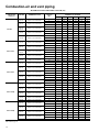
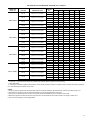
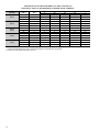
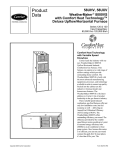
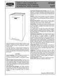
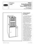
Product
Data
58MVP
Deluxe 4-Way Multipoise
Direct-Vent Variable-Capacity
Condensing Gas Furnace
Series 130
Input Capacities: 40,000 thru 120,000 Btuh
Variable capacity,
the ultimate in
heating comfort . . .
•••••
U L T R
A
G A S
Copyright 1998 Carrier Corporation
®
•••••
H I G H
•••••
E F F I C
I E N C Y
F U R N
A N C E
With the model 58MVP
WeatherMakerTM Infinity Furnace,
we’ve taken the ultimate in heating
comfort and made it better.
The model 58MVP is available in 6
heat/airflow combinations. The unit
has a 4-way multipoise design and can
be installed in upflow, downflow, or
horizontal positions covering up to
24 different applications.
The WeatherMaker Infinity achieves
industry-leading ultra-high efficiency
at up to 96.6 percent Annual Fuel
Utilization Efficiency (AFUE).
Efficient performance is enhanced
through the variable-capacity design.
To maintain ideal comfort, the control
system of the WeatherMaker Infinity
automatically adjusts, maximizing the
use of low operating speeds that
produce near silent furnace operation
while meeting the exact heating
needs. This unit is designed to keep
the indoor temperature within
1 degree of the thermostat setpoint.
Because it operates in low speed most
of the time, the model 58MVP uses
up to 80% less power than singlecapacity furnaces.
In addition to providing optimum
comfort, the model 58MVP has a
sealed combustion system. This
system brings combustion air from
outdoors to the furnace and vents
flue gases safely outside the home.
Because it is sealed, operational noise
is minimal. A sealed combustion
system also means fewer cold drafts
and less air infiltration.
Quality materials are the key behind
the model 58MVP’s outstanding
performance. Carrier stands behind
Form 58MVP-7PD
quality. We offer lifetime warranty
protection* on the heat exchangers, the
heart of the WeatherMaker Infinity.
The microprocessor control center, the
variable-speed inducer motor, and the
variable-speed blower motor are all
backed by a 5-year Limited Warranty.
There is a 3-year Limited Warranty on
hot surface ignition (HSI).
The versatile 4-way multipoise design
in conjunction with variable capacity
makes the 58MVP ideal for use with
split-system cooling, including
2-speed units. A Carrier electronic
air cleaner, humidifier, thermostat,
comfort ventilator, and Comfort
ZoneTM will provide year-round
comfort and efficiency.
Designed for durability, comfort,
and reliability, the model 58MVP
WeatherMaker Infinity is the ultimate
in versatile, efficient comfort.
58MVP FEATURES/
BENEFITS
Variable Heating Capacity — On the
coldest days of the year, the 58MVP
Furnace has the capacity to heat your
home. On moderate days when less
heat is required, this furnace will
regulate itself to a lower capacity —
providing a comfortable home and
minimizing operating costs.
Insulated Blower Compartment —
The acoustical insulation reduces air
and motor noise for quiet operation.
Certifications — The 58MVP units
are A.G.A. and C.G.A. design certified
for use with natural and propane gases.
The furnace is factory-shipped for use
with natural gas. An A.G.A./C.G.A.
listed gas conversion kit is required to
convert furnace for use with propane
gas. The efficiency is GAMA efficiency
rating certified. The 58MVP meets
California Air Quality Management
District emission requirements.
Quality Registration — The 58MVP
is engineered and manufactured under
an ISO 9001 registered quality system.
Venting — The combustion-air and
vent pipes can terminate through a side
wall or through the roof when used
with a factory-authorized vent
termination kit.
Blower Access Panel Switch —
Automatically shuts off 115-v power
to furnace whenever blower access
panel is opened.
Reliable Heat Exchanger Design —
The primary heat exchanger is made of
aluminized steel for corrosion
resistance.
The SerpentuffTM condensing heat
exchanger cells are laminated with
polypropylene for greater resistance to
corrosion and epoxy coated externally
to prevent oxidation. This breakthrough in heating technology helps
extend the life of the furnace for years
of dependable performance. The heat
exchanger is positioned in the
furnace to extract additional heat.
Warranty — The 58MVP heat
exchangers come with a Limited
Warranty for lifetime of original
owner in single family residence;
20 years in other residential and
commercial applications. Contact
your dealer for details.
Electronic Variable-Speed Motors
— ICM Motors (Integrated Control
and Motor) provide variable-speed
operation to optimize comfort levels in
the home. They are also more
economical to operate than standard
motors. Motor and electronic controls
are guaranteed by a 5-year Limited
Warranty.
Microprocessor Control Center —
The microprocessor control center
features state-of-the-art combustion,
temperature, and airflow control to
maximize comfort while operating at
peak efficiency.
Combustion control is obtained by
taking the appropriate inducer motor
RPM readings when the low- and
high-fire pressure switches are
made. Using this information, the
microprocessor maintains a consistent
air-to-fuel ratio independent of vent
sizing and conditions.
The first cycle after power reset
provides 16 minutes of low heat
before switching to high heat unless
the room thermostat has been satisfied.
Subsequent thermostat cycles provide
anywhere from 0 to 16 minutes of low
heat depending on the length of the
previous thermostat cycle.
Airflow control is accomplished by
using a technique involving the
microprocessor and blower motor. The
static load on the air delivery system is
measured each heating cycle. The
microprocessor then uses this
information to deliver correct airflow
independent of variations in system
restrictions. (For example, dirty filter or
zone damper changes during a cycle.)
A special dehumidification function
allows direct input from a thermidistat
or humidistat. This input adjusts
system airflow for greater humidity
removal and increased cooling comfort
during summer months.
Insulation — Foil-faced insulation in
heat exchanger section of the casing
minimizes heat loss.
Direct Vent Sealed Combustion
System — Model 58MVP uses 100
percent outdoor air, which results in
especially quiet operation. Direct
venting minimizes the possibility of
chloride contamination which can result
in heat exchanger corrosion and also
reduces air infiltration into the home.
Monoport Burners — The burners
are finely tuned for smooth, quiet
combustion and economical operation.
Bottom Closure — Factory-installed
for side return; easily removable for
bottom return.
HUM
G
G
2
W/W1
COM
SEC-1
COM
24V
DEHUM
4
Not field repairable
1012-97-943 REV. C
SEC-2
O1 2 3
N
3
2
3
1
LED
Status
EAC 115VAC 60Hz 1.0 A Max.
Humidifier 24VAC 60Hz 0.5A Max.
Input 24VAC 60Hz 225mA
ANSI Z21.20 - 1993 Automatic Gas
Ignition Systems and Components
SERVICE
CAN/CSA - C22.2 No. 199-M89
Combustion Safety Controls and Solid-State
Ignitors for Gas and Oil-Burning Equipment.
W2
W/W1
W2
See furnace wiring label, LED status code
label, and instructions.
United Technologies Electronic Controls
Huntington, IN 46750
Furnace Control
Part Number: HK42FZ012
WARNING
HEAT EXCHANGERS
Y/Y2
R
R
Y/Y2
A92505
HUM
*See warranty information for details.
O1 2 3
N
ON
1 2 3 4 5 6 7 8
CONTROL CENTER
A95168
A93005
INDUCER ASSEMBLY
13
1
2
3
4
5
14
6
6
7
9
16
15
17
18
19
8
10
11
12
20
A96275
NOTES:
1. The 58MVP Furnace is built for use with natural gas. The furnace can be converted for propane gas with a factory-authorized and
listed accessory conversion kit.
2. Control location and actual controls may be different than shown above.
1
Burner sight glass for viewing burner flame.
11
2
Burner assembly (inside). Operates with energysaving, inshot burners and hot surface ignitor for
safe, dependable heating.
Heavy-duty blower. Circulates air across the
heat exchangers to transfer heat into the home.
12
Air filter and retainer. May be used for side
return application.
3
Combustion-air intake connection to ensure
contaminant-free air (right or left side).
13
Rollout switch (manual reset) to prevent
overtemperature.
4
Redundant 2-stage gas valve. Safe, efficient.
Features 1 gas control with 2 internal shutoff
valves.
14
5
Junction box for 115-v electrical power supply.
Primary serpentine heat exchanger (inside).
Stretches fuel dollars with the S-shaped heatflow design. Solid construction of corrosionresistant aluminized steel means reliability.
6
Vent outlet. Uses PVC pipe to carry vent gases
from the furnace’s combustion system (right or
left side).
15
3-amp fuse provides electrical and component
protection.
7
Secondary condensing heat exchanger (inside).
Wrings out more heat through condensation.
Constructed with Polypropylene-laminated steel
to ensure durability.
16
Light emitting diodes (LEDs) on control center.
Code lights are for diagnosing furnace operation
and service requirements.
17
Control center.
8
Pressure switches ensure adequate flow of flue
products through furnace and out vent system.
18
Blower access panel safety interlock switch.
9
Inducer motor. Pulls hot flue gases through the
heat exchangers, maintaining negative pressure
for added safety.
19
Transformer (24v) behind control center
provides low-voltage power to furnace control
center and thermostat.
10
Condensate drain connection. Collects moisture
condensed during combustion process.
20 Limit switch (manual reset).
3
Model number nomenclature
58MVP
040
130
14
Deluxe 4-Way Multipoise
Variable-Capacity Direct-Vent
Condensing Gas Furnace
Input Capacity (Low/High)
040 — 26,000/40,000 Btuh
060 — 39,000/60,000 Btuh
080 — 52,000/80,000 Btuh
100 — 65,000/100,000 Btuh
120 — 78,000/120,000 Btuh
Cooling Size Airflow
(400 CFM per 12,000 Btuh)
14 — 1400 CFM
20 — 2000 CFM
Series
Carrier accessories*
UNIT SIZE
040-14
060-14
080-14
080-20
GAS CONVERSION KIT — NATURAL-TO-PROPANE*
KGANP25012SP
GAS CONVERSION KIT — PROPANE-TO-NATURAL*
KGAPN20012SP
DOWNFLOW BASE (For Combustible Floors)†
100-20
KGASB0201ALL
VENT TERMINATION KIT (Bracket Only for 2 Pipes)
2-in. — KGAVT0101BRA
3-in. — KGAVT0201BRA
CONCENTRIC TERMINATION KIT (Single Exit)
2-in. — KGAVT0501CVT
3-in. — KGAVT0601CVT
CONDENSATE FREEZE PROTECTION KIT
KGAHT0101CFP
SIDE FILTER RACK (Without Filter) Upflow Only‡
KGAFR0206ALL
ADVANCED PRODUCT MONITOR
KGAFP0101APM
ELECTRONIC AIR CLEANER (EAC)‡
MECHANICAL AIR CLEANER
HUMIDIFIER
HEAT RECOVERY VENTILATOR
ENERGY RECOVERY VENTILATOR
120-20
Model AIRA
Model 31MF or MACA
Model HUM
Model VA3B, VB5B, or VC5B
Model VL3A
THERMOSTAT — NON-PROGRAMMABLE
(Furnace Staging Determined by Furnace Control)
For Use with 1-Speed Air Conditioner — TSTATCCNAC01-B
For Use with 2-Speed Air Conditioner — TSTATCCN2S01-B
For Use with 2-Speed Heat Pump — TSTATCCN2S01-B
THERMOSTAT — PROGRAMMABLE
(Furnace Staging Determined by Furnace Control)
For Use with 1-Speed Air Conditioner — TSTATCCPAC01-B
For Use with 2-Speed Air Conditioner — TSTATCCP2S01-B
For Use with 1-Speed Heat Pump — TSTATCCPDF01-B
For Use with 2-Speed Heat Pump — TSTATCCP2S01-B or TSTATCCPDF01-B
THERMOSTAT — NON-PROGRAMMABLE
(Furnace Staging Determined by Thermostat)
For Use with 1-Speed Air Conditioner — TSTATCCNHP01-B
For Use with 2-Speed Air Conditioner — TSTATCCN2S01-B
For Use with 2-Speed Heat Pump — TSTATCCN2S01-B
THERMOSTAT — PROGRAMMABLE
(Furnace Staging Determined by Thermostat)
For Use with 1-Speed Air Conditioner — TSTATCCPHP01-B
For Use with 2-Speed Air Conditioner — TSTATCCP2S01-B
For Use with 1-Speed Heat Pump — TSTATCCPDF01-B
For Use with 2-Speed Heat Pump — TSTATCCP2S01-B or TSTATCCPDF01-B
THERMIDISTAT**
TSTATCCPRH01-B
ZONING — 2 ZONE
ZONEKIT2ZCAR, ZONECC2KIT01
ZONING — 4 ZONE
ZONECC4KIT01
ZONING — 8 ZONE
ZONECC8KIT01
* Factory-authorized and field-installed. Gas conversion kits are A.G.A. recognized.
† Required for installation on combustible floors when no coil box is used, or when any coil box other than a Carrier CD5, CK5, or KCAKC cased
coil is used.
‡ An external filter is required for right-side return-air installations.
** High-pressure switch must be used when operating a dual fuel system. Outdoor Temperature Sensor is packaged with the Thermidistat Control
and dual fuel thermostat to gain the full benefit and features.
4
FILTER FRAME
FILTER
B
C
A
FURNACE
DOOR
A93086
A93068
SIDE FILTER
RACK
Custom-made filter rack for
easy connection when as
return plenum already exists.
Provides easy access for
cleaning filter.
A concentric vent kit allows
vent and combustion-air
pipes to terminate through a
single exit in a roof or side
wall.
Accepts one 16 x 25 x 1 in. filter.
(Not included)
One pipe runs inside the other
allowing venting through the
inner pipe and combustion air
to be drawn in through the outer pipe.
A
A88202
CONCENTRIC
VENT
23-1/8 in.
B
2-3/8 in.
C
14-1/2 in.
DOWNFLOW
SUBBASE
One base fits all furnace
sizes. The base is designed
to be installed between the
furnace and a combustible
floor when no coil box is used
or when a coil box other than
a Carrier cased coil is used. It
is A.G.A. design certified for
use with Carrier 58MVP furnaces when installed in
downflow applications.
®
A97152
A95248
A97432
A94336
ELECTRONIC OR
MECHANICAL
AIR CLEANER
HUMIDIFIER
CONTROLS:
THERMOSTATS
AND ZONING
ENERGY/HEAT
RECOVERY
VENTILATOR
Cleans the air of smoke, dirt,
and many pollens commonly
found. Saves decorating and
cleaning expenses by keeping carpets, furniture, and
drapes cleaner.
By adding moisture to winterdry air, a Carrier humidifier
can often improve comfort
and keeps woodwork, wallpaper, and paint in better
condition. Moisturizing
household air also helps to
retain normal body heat and
provides comfort at lower
temperatures.
Available in programmable
and non-programmable models, Carrier thermostats maintain a constant, comfortable
temperature level in the
home.
Carrier’s energy or heat
recovery ventilators exhaust
stale indoor air and provide
fresh outdoor air to the home
while minimizing heat loss
and humidity level. Especially
useful for today’s tighter
constructed houses.
Electronic air cleaner is
shown.
For the ultimate in home
comfort, Carrier’s 2-, 4-, or
8-zone systems allow temperature control of individual
“zones” of the home. This is
accomplished through a
series of electronic dampers
and remote room sensors.
The 4-zone system is shown.
Energy recovery ventilator is
shown.
5
Physical data
UNIT SIZE
040-14
060-14
080-14
080-20
100-20
120-20
Upflow
25,000
37,000
49,000
49,000
61,000
73,000
(Shaded capacities are
Downflow
25,000
36,000
49,000
49,000
61,000
73,000
specified on rating plate)
Horizontal
25,000
36,000
49,000
49,000
61,000
73,000
113,000
OUTPUT CAPACITY BTUH* (ICS)
Low
High
Upflow
38,000
57,000
75,000
75,000
94,000
Downflow
37,000
56,000
75,000
75,000
94,000
113,000
Horizontal
37,000
56,000
75,000
75,000
93,000
112,000
Low
26,000
39,000
52,000
52,000
65,000
78,000
High
40,000
60,000
80,000
80,000
100,000
120,000
205
170
182
204
203
234
Low
35 — 45
60 — 70
60 — 70
60 — 70
60 — 70
60 — 70
High
40 — 50
45 — 55
45 — 55
45 — 55
55 — 65
55 — 65
0.20
INPUT BTUH†
SHIPPING WEIGHT (Lb)
CERTIFIED TEMP RISE RANGE (°F)
CERTIFIED EXT STATIC PRESSURE (ESP)
Heating
0.10
0.12
0.15
0.15
0.20
(In. wc)
Cooling
0.50
0.50
0.50
0.50
0.50
0.50
565 (650**)
515 (590**)
690 (795**)
690 (795**)
860 (990**)
1035 (1190**)
Heating High
780
1010
1345
1345
1425
1710
Cooling (Max)
1400
1400
1400
2000
2000
2000
AIRFLOW CFM‡
Heating Low
LIMIT CONTROL
SPST
HEATING BLOWER CONTROL (Off Delay)
BURNERS (Monoport)
Selectable 90, 135, 180, or 225 Sec Intervals
2
3
GAS CONNECTION SIZE
4
4
5
6
1/2-in. NPT
GAS VALVE (Redundant) Manufacturer
White-Rodgers
Minimum Inlet Pressure (In. wc)
4.5 (Natural Gas)
Maximum Inlet Pressure (In. wc)
13.6 (Natural Gas)
IGNITION DEVICE
Hot Surface
* Capacity in accordance with U.S. Government DOE test procedures.
† Gas input ratings are certified for elevations to 2000 ft. For elevations above 2000 ft, reduce ratings 2% for each 1000 ft above sea level.
In Canada, derate the unit 5% for elevations from 2000 to 4500 ft above sea level.
‡ Airflow shown is for bottom only return-air supply. For air delivery above 1800 CFM, see Air Delivery curve for other options. A filter is required for
each return-air supply.
** Low heat CFM when bypass humidifier switch (SW-3) on control center is used.
ICS — Isolated Combustion System
MEETS DOE RESIDENTIAL CONSERVATION SERVICES
PROGRAM STANDARDS.
®
ama
CANADIAN GAS ASSOCIATION
A PP R O VED
R
Before purchasing this appliance, read important
energy cost and efficiency information available
from your retailer.
As an ENERGY STARSM Partner, Carrier Corporation
has determined that this product meets the
ENERGY STAR guidelines for energy efficiency.
REGISTERED QUALITY SYSTEM
These products are engineered and manufactured under an
ISO 9001 registered quality system.
6
Performance data
UNIT SIZE
040-14
060-14
080-14
080-20
100-20
120-20
DIRECT-DRIVE MOTOR Hp (ICM)
1/2
1/2
1/2
1
1
3/4
MOTOR FULL LOAD AMPS
7.7
7.7
7.7
12.4
12.4
9.6
11 x 10
11 x 10
RPM (Nominal) — SPEEDS
Variable 250 — 1300
BLOWER WHEEL DIAMETER x WIDTH (In.)
FILTER SIZE (In.) NOMINAL (Washable)
11 x 10
10 x 7
11 x 10
11 x 10
(2) 16 x 25 x 1 (1) 16 x 25 x 1 (1) 20 x 25 x 1 (1) 20 x 25 x 1 (1) 20 x 25 x 1 (2) 16 x 25 x 1
ICM — Integrated Control and Motor
EFFICIENCY
UNIT SIZE
040-14
060-14
080-14
080-20
100-20
120-20
Upflow
25,000
37,000
49,000
49,000
61,000
73,000
(Shaded capacities are
Downflow
25,000
36,000
49,000
49,000
61,000
73,000
specified on rating plate)
Horizontal
25,000
36,000
49,000
49,000
61,000
73,000
113,000
CAPACITY BTUH* (ICS)
Low
High
AFUE%*
Upflow
38,000
57,000
75,000
75,000
94,000
Downflow
37,000
56,000
75,000
75,000
94,000
113,000
Horizontal
37,000
56,000
75,000
75,000
93,000
112,000
Upflow
96.6
94.1
94.1
94.1
94.1
94.1
Downflow
95.0
92.7
92.7
92.7
92.7
92.7
Horizontal
96.1
93.7
93.7
93.7
93.7
93.7
* Ratings in accordance with U.S. Government DOE test procedures.
ICS — Isolated Combustion System
7
AIR DELIVERY — CFM (With Filter)* AND POWER DRAW (WATTS)**
UNIT
SIZE
OPERATING
MODE
AIRFLOW
CFM
External Static
Pressure Range*
External Static Pressure (ESP)
0.1
0.2
0.3
040-14
0.4
0.5
0.6
0.7
0.8
Power Draw (WATTS)**
Low Heat
565 (650†)
0–0.26
59
79
94
—
—
—
—
—
High Heat
780
0–0.49
96
123
149
172
197
—
—
—
1-1/2 A/C Setting
600
0–0.29‡
64
84
99
—
—
—
—
—
2-Ton A/C Setting
800
0–0.51
102
129
155
179
204
230
—
—
2-1/2-Ton A/C Setting
1000
0–0.80
164
191
225
256
292
321
354
396
3-Ton A/C Setting
1200
0–0.80
255
294
328
367
404
447
485
524
3-1/2-Ton A/C Setting
1400
0–0.43††
386
433
483
528
544
551
555
560
060-14
Low Heat
515 (590†)
0–0.21
56
68
88
—
—
—
—
—
High Heat
1010
0–0.80
177
199
237
263
283
315
352
375
1-1/2 A/C Setting
600
0–0.29‡
68
88
106
—
—
—
—
—
2-Ton A/C Setting
800
0–0.51‡
118
136
156
179
198
223
—
—
2-1/2-Ton A/C Setting
1000
0–0.80
174
196
232
259
279
309
348
370
3-Ton A/C Setting
1200
0–0.80
266
294
338
358
395
427
453
498
3-1/2-Ton A/C Setting
1400
0–0.52††
387
415
456
507
548
560
560
560
080-14
Low Heat
690 (795†)
0–0.26
73
92
107
—
—
—
—
—
High Heat
1345
0–0.64
311
342
383
428
469
510
535
535
1-1/2 A/C Setting
600
0–0.20‡
59
78
—
—
—
—
—
—
2-Ton A/C Setting
800
0–0.36‡
92
109
124
137
—
—
—
—
2-1/2-Ton A/C Setting
1000
0–0.56‡
128
167
208
237
268
299
—
—
3-Ton A/C Setting
1200
0–0.80‡
232
261
297
336
371
408
437
483
3-1/2-Ton A/C Setting
1400
0–0.55††
345
377
427
470
513
535
535
535
080-20
Low Heat
690 (795†)
0–0.25
93
111
132
—
—
—
—
—
High Heat
1345
0–0.80
343
376
416
457
503
535
570
613
—
2-Ton A/C Setting
800
0–0.34‡
114
136
163
189
—
—
—
2-1/2-Ton A/C Setting
1000
0–0.53‡
175
200
232
264
295
324
—
—
3-Ton A/C Setting
1200
0–0.76‡
263
294
333
365
404
429
474
506
3-1/2-Ton A/C Setting
1400
0–0.80
375
410
457
501
544
579
629
679
4-Ton A/C Setting
1600
0–0.80
524
579
631
691
733
791
832
883
5-Ton A/C Setting
2000
0–0.32††
947
1034
1103
1110
1110
1110
1110
1073
100-20
Low Heat
860 (990†)
0–0.34
105
121
138
161
—
—
—
—
High Heat
1425
0–0.80
299
340
385
419
464
500
540
573
2-Ton A/C Setting
800
0–0.29‡
96
112
127
—
—
—
—
—
2-1/2-Ton A/C Setting
1000
0–0.46‡
130
154
176
194
220
—
—
—
3-Ton A/C Setting
1200
0–0.66‡
191
220
253
284
326
357
395
—
3-1/2-Ton A/C Setting
1400
0–0.80
286
322
369
403
447
481
522
556
4-Ton A/C Setting
1600
0–0.80
410
468
507
544
588
642
678
720
5-Ton A/C Setting
2000
0–0.37††
788
836
903
962
954
938
927
916
120-20
Low Heat
High Heat
2-Ton A/C Setting
1035 (1190†)
0–0.34
140
168
194
219
—
—
—
—
1710
0–0.80
474
519
562
601
652
690
735
780
800
0–0.20‡
89
111
—
—
—
—
—
—
2-1/2-Ton A/C Setting
1000
0–0.32‡
133
156
182
207
—
—
—
—
3-Ton A/C Setting
1200
0–0.46‡
194
229
257
286
314
—
—
—
3-1/2-Ton A/C Setting
1400
0–0.62‡
281
319
354
393
423
458
495
—
4-Ton A/C Setting
1600
0–0.80
397
441
473
518
562
597
638
682
5-Ton A/C Setting
2000
0–0.30††
740
799
824
835
846
861
872
888
2
* Actual external static pressure (ESP) can be determined by using the fan laws (CFM
proportional to ESP); such as, a system with 1010 CFM
at 0.5 ESP would operate at cooling airflow of 800 CFM at 0.31 ESP and low-heating airflow of 515 CFM at 0.13 ESP. (See air delivery curves.)
† Low heat CFM when bypass humidifier switch (SW3) on control center is used. The listed low-heating wattage is with bypass humidifier switch
(SW3) OFF.
‡ Ductwork must be sized for high-heat CFM within the operational range of ESP.
** Wattage data provided is for the circulating blower with bottom only return-air supply and does not include draft inducer, accessories, or gas controls.
†† Refer to the air delivery curves for airflow CFM above this ESP
8
AIR DELIVERY CURVE — 040-14
AIR DELIVERY CURVE — 060-14
Constant System
Curves
0.7
0.6
External Static Pressure (in. wc)
External Static Pressure (in. wc)
HIGH
HEAT
0.8
0.8
HIGH
HEAT
0.5
0.4
LOW
HEAT
0.3
0.2
Constant System
Curves
0.7
0.6
0.5
LOW
HEAT
0.4
0.3
0.2
0.1
0.1
11⁄2 Ton
0
500
600
21⁄2 Ton
2 Ton
700
800
900
1000
1100
31⁄2
Ton
3 Ton
1200
1300
1400
11⁄2 Ton
0
500
1500
600
21⁄2 Ton
2 Ton
700
800
900
1000
1100
31⁄2
Ton
3 Ton
1200
1300
1400
CFM
A93074
A97319
AIR DELIVERY CURVE — 080-20
AIR DELIVERY CURVE — 080-14
HIGH
HEAT
0.7
0.6
Constant System
Curves
0.4
LOW
HEAT
0.3
HIGH
HEAT
0.8
External Static Pressure (in. wc)
External Static Pressure (in. wc)
0.8
0.5
0.2
0.1
Constant System
Curves
0.7
0.6
0.5
LOW
HEAT
0.4
0.3
0.2
0.1
11⁄2 Ton
21⁄2 Ton
2 Ton
0
31⁄2 Ton
3 Ton
600
700
800
900
1000
1100
1200
1300
1400
1500
21⁄2 Ton
2 Ton
0
500
600
800
1000
3 Ton
31⁄2 Ton
4 Ton
1200
CFM
1400
1600
5 Ton
1800
A97321
AIR DELIVERY CURVE — 100-20
AIR DELIVERY CURVE — 120-20
HIGH
HEAT
0.8
External Static Pressure (in. wc)
0.6
0.5
LOW
HEAT
0.4
HIGH
HEAT
0.8
Constant System
Curves
0.7
0.3
0.2
0.1
Constant System
Curves
0.7
0.6
0.5
LOW
HEAT
0.4
0.3
0.2
SINGLE
SIDE
RETURN
0.1
21⁄2 Ton
2 Ton
0
700
900
1100
31⁄2 Ton
3 Ton
1300
2000
CFM
A97320
External Static Pressure (in. wc)
1500
CFM
1500
4 Ton
1700
5 Ton
1900
2100
CFM
0
2 Ton
700
21⁄2 Ton
900
3 Ton
1100
31⁄2 Ton
1300
1500
4 Ton
1700
5 Ton
1900
2100
CFM
A97322
A98564
NOTE: Curves shown are when; 1 side only, both sides, a combination of 1 side and bottom, or bottom only return-air openings of the furnace are used
except as shown on the 120-20 curve.
9
Dimensions
CONCENTRIC VENT
B IN. DIA PVC
VENT/EXHAUST
F
E
C IN. DIA
13/16
11/2
D
A
B IN. DIA PVC
INTAKE/COMBUSTION AIR
A97110
DIMENSIONS (in.)
KIT PART NO.
A*
B
C
D†
E
F
KGAVT0501CVT
33-3/8
2
3-1/2
16-5/8
6-1/4
5-3/4
KGAVT0601CVT
38-7/8
3
4-1/2
21-1/8
7-3/8
6-1/2
* Dimension A will change accordingly as dimension D is lengthened or shortened.
† Dimension D may be lengthened to 60 in. maximum. Dimension D may also be shortened by cutting the pipes provided in the kit to 12 in. minimum.
CONDENSATE TRAP
FURNACE
DOOR
BLOWER SHELF
CONDENSATE
TRAP
CONDENSATE
TRAP (INSIDE)
FURNACE
DOOR
FURNACE
SIDE
4 78
FURNACE
SIDE
4
534
534
4
FIELD
DRAIN
CONN
ALTERNATE DRAIN
TUBE LOCATION
26 1 4
26 1 4
11 2
SIDE VIEW
CONDENSATE TRAP
DRAIN TUBE LOCATION
FIELD
DRAIN
CONN
FRONT VIEW
END VIEW
SLOT FOR SCREW
HORIZONTAL
APPLICATION
(OPTIONAL)
FRONT VIEW
HORIZONTAL
APPLICATIONS
DOWNFLOW AND ALTERNATE
EXTERNAL UPFLOW APPLICATIONS
UPFLOW APPLICATIONS
34
1⁄4
OD
COLLECTOR BOX TO
TRAP RELIEF PORT
11 2
1⁄2
OD
INDUCER HOUSING
DRAIN CONNECTION
34
5⁄8
OD
COLLECTOR BOX
DRAIN CONNECTION
71 8
SCREW HOLE FOR
UPFLOW OR DOWNFLOW APPLICATIONS
(OPTIONAL)
13 4
WIRE TIE
GUIDES
(WHEN USED)
FRONT VIEW
78
21 4
1⁄2-IN.
PVC OR CPVC
SIDE VIEW
A93026
10
11
11⁄4"
1"
14 1⁄2"
TYP
26 15⁄16"
1⁄2-IN.
⁄16"
11
E
INLET
OUTLET
D
A
AIRFLOW
⁄16"
11
A
24-1/2*
17-1/2
21
21
21
24-1/2
040-14*
060-14
080-14
080-20
100-20
120-20
DIMENSIONS (In.)
D
22-7/8
19-3/8
19-3/8
19-3/8
15-7/8
22-7/8*
18 1⁄4"
TYP
9⁄16"
DIMPLE LOCATORS
FOR HORIZONTAL
HANGING
CONDENSATE
DRAIN LOCATION
(UPFLOW)
30 1⁄2"
CONDENSATE DRAIN
TRAP LOCATION
(DOWNFLOW &
HORIZONTAL RIGHT)
OR ALTERNATE
1
⁄2-IN. DIA GAS CONN
⁄16"
13
NOTES: Minimum return-air opening at furnace, based on metal
duct. If flex duct is used, see flex duct manufacturer's
recommendation for equivalent diameters:
1. For 800 CFM 16-in. round or 14- 1/2 X 12-in. rectangle.
2. For 1200 CFM 20-in. round or 14- 1/2 X 19-1/2 in. rectangle.
3. For 1600 CFM 22-in. round or 14- 1/2 X 23-1/4 in. rectangle.
4. For airflow requirements above 1800 CFM, see Air Delivery
Curve in Product Data literature for specific use of single side
inlets. The use of both side inlets, a combination of 1 side and
the bottom, or the bottom only will ensure adequate return-air
openings for airflow requirements above 1800 CFM.
UNIT SIZE
CONDENSATE
DRAIN LOCATION
(UPFLOW)
9
TYP
7⁄16"
33 1⁄4"
TYP
32 5⁄8"
TYP
30 13⁄16"
29 11⁄16"
TYP
27 5⁄8"
27 9⁄16"
TYP
24 1⁄2"
17 5⁄16"
CONDENSATE
DRAIN TRAP
LOCATION
(ALTERNATE
UPFLOW)
⁄8-IN. DIA
ACCESSORY
POWER ENTRY
7
⁄8-IN. DIA
POWER CONN
7
CONDENSATE DRAIN
TRAP LOCATION
(DOWNFLOW &
HORIZONTAL LEFT)
⁄16"
13
* These dimensions reflect the wider casing for the 96.6% AFUE furnace.
26 15⁄16" TYP
23 1⁄4" TYP
SIDE INLET
SIDE INLET
DIA THERMOSTAT
ENTRY
22 11⁄16"
2-IN. VENT CONN
⁄2-IN. DIA
GAS CONN
1
2-IN. COMBUSTIONAIR CONN
22 5⁄16"
24 1⁄2"
26 1⁄4"
E
23
19-1/2
19-1/2
19-1/2
16
23*
24 3⁄16"
BOTTOM INLET
22 1⁄4" TYP
SIDE INLET
22 11⁄16"
2-IN. VENT CONN
⁄2-IN. DIA
THERMOSTAT ENTRY
1
DIA
POWER CONN
7⁄8-IN.
DIA
GAS CONN
1⁄2-IN.
2-IN. COMBUSTIONAIR CONN
OUTLET
19"
22 5⁄16"
26 1⁄4"
26 15⁄16"
28 1⁄2"
11
A98566
⁄16"
7⁄16"
1"
39 7⁄8"
5⁄16"
5⁄8"
13⁄16"
DOWNFLOW SUBBASE — DIMENSIONS (In.)
FURNACE
CASING
WIDTH
FURNACE IN DOWNFLOW APPLICATION
PLENUM OPENING*
A
B
17-1/2
FLOOR OPENING
C
D
HOLE NO.
FOR WIDTH
ADJUSTMENT
Furnace with or without CD5 or CK5 Coil
Assembly or KCAKC Coil Box
15-1/8
19
16-3/4
20-3/8
3
21
Furnace with or without CD5 or CK5 Coil
Assembly or KCAKC Coil Box
18-5/8
19
20-1/4
20-3/8
2
24-1/2
Furnace with or without CD5 or CK5 Coil
Assembly or KCAKC Coil Box
22-1/8
19
23-3/4
20-3/8
1
* The plenum should be constructed 1/4-in. smaller in width and depth than the plenum dimensions shown above.
LOCATING
TAB
1 1/4″ TYP
PLENUM
OPENING
B
A
D
1
2
3
4
LOCATING
TAB
C
FACTORY-SUPPLIED
FIELD-INSTALLED
INSULATION
4
A97427
Assembled
12
3
2
A88207
Disassembled
1
Electrical data
UNIT SIZE
040-14
060-14
080-14
UNIT VOLTS — HERTZ — PHASE
080-20
100-20
120-20
115 — 60 — 1
OPERATING VOLTAGE RANGE (Min — Max)*
104 — 127
MAXIMUM UNIT AMPS
8.9
8.9
8.9
13.8
13.8
11.6
UNIT AMPACITY†
12.0
12.0
12.0
17.9
18.1
15.3
MINIMUM WIRE SIZE
14
14
14
12
12
12
MAXIMUM WIRE LENGTH (Ft)‡
31
31
31
32
32
37
MAXIMUM FUSE SIZE OR CKT BKR (Amps)**
15
15
15
20
20
20
TRANSFORMER (24v)
40va
EXTERNAL CONTROL POWER AVAILABLE Heating
25va
Cooling
34va
AIR CONDITIONING BLOWER RELAY
Standard
* Permissible limits of the voltage range at which the unit will operate satisfactorily.
† Unit ampacity = 125% of largest operating component’s full load amps plus 100% of all other potential operating component’s (EAC, humidifier,
etc.) full load amps.
‡ Length shown is as measured 1 way along wire path between unit and service panel for maximum 2% voltage drop.
** Time-delay type is recommended.
Typical wiring schematic
FIELD 24-V WIRING
FIELD 115-, 208/230-, 460-V WIRING
FACTORY 24-V WIRING
FACTORY 115-, 208/230-, 460-V WIRING
NOTE 5
W
FIVE
WIRE
C
R
G
Y
THERMOSTAT
TERMINALS
FIELD-SUPPLIED
DISCONNECT
THREE-WIRE
HEATING
ONLY
208/230- OR
460-V
THREE PHASE
W/W1
GND
115-V
SINGLE
PHASE
W2
NOTE
3
GND
R
AUXILIARY
115-V
FIELD-SUPPLIED J-BOX
DISCONNECT
SWITCH
FURNACE
CONTROL
CENTER
208/230-V
SINGLE
PHASE
G
C
GND
NOTE 1
Y/Y2
24-V
TERMINAL
BLOCK
GND
CONDENSING
UNIT
TWO WIRE
NOTES:
1. Connect Y or Y/Y2 terminal as shown for proper cooling operation.
2. Proper polarity must be maintained for 115-v wiring.
3. Use W2 with 2-stage thermostat when zoning.
4. If any of the original wire, as supplied, must be replaced, use
same type or equivalent wire.
5. Some thermostats require a "C" terminal connection as shown.
A98325
13
Combustion-air and vent piping
MAXIMUM ALLOWABLE PIPE LENGTH (FT)
ALTITUDE
ABOVE SEA
LEVEL (FT)
0 to 2000
UNIT SIZE
040-14
2 Pipe or 2-In. Concentric
060-14
2 Pipe or 2-In. Concentric
080-14
080-20
2 Pipe or 2-In. Concentric
100-20
2 Pipe or 2-In. Concentric
120-20
040-14
2001 to 3000
080-14
080-20
2 Pipe or 2-In. Concentric
100-20
2 Pipe or 2-In. Concentric
080-14
080-20
2 Pipe or 2-In. Concentric
2 Pipe or 2-In. Concentric
2 Pipe or 3-In. Concentric
040-14
2 Pipe or 2-In. Concentric
060-14
2 Pipe or 2-In. Concentric
080-14
080-20
2 Pipe or 2-In. Concentric
100-20
2 Pipe or 2-In. Concentric
120-20
2 Pipe or 3-In. Concentric
040-14
14
2 Pipe or 2-In. Concentric
2 Pipe or 2-In. Concentric
120-20
See notes on pg. 15.
2 Pipe or 3-In Concentric
060-14
100-20
5001 to 6000‡
2 Pipe or 2-In. Concentric
2 Pipe or 2-In. Concentric
040-14
4001 to 5000‡
2 Pipe or 3-In. Concentric
060-14
120-20
3001 to 4000
TERMINATION TYPE
2 Pipe or 2-In. Concentric
060-14
2 Pipe or 2-In. Concentric
080-14
080-20
2 Pipe or 2-In. Concentric
100-20
2 Pipe or 2-In. Concentric
120-20
2 Pipe or 3-In. Concentric
PIPE DIA
(IN.)*
NUMBER OF 90° ELBOWS
1
2
3
4
5
6
1-1/2
50
45
40
35
30
25
2
70
70
70
70
70
70
1-1/2
50
45
40
35
30
25
2
70
70
70
70
70
70
1-1/2
30
25
20
15
10
5
2
70
70
70
70
70
70
20
2
45
40
35
30
25
2-1/2
70
70
70
70
70
70
2-1/2
10
NA
NA
NA
NA
NA
NA
3
35
30
15
NA
NA
3†
70
70
70
70
70
70
1-1/2
45
40
35
30
25
20
70
2
70
70
70
70
70
1-1/2
45
40
35
30
25
20
2
70
70
70
70
70
70
1-1/2
26
21
16
11
6
NA
2
70
70
70
70
70
70
15
2
40
35
30
25
20
2-1/2
70
70
70
70
70
70
3
31
26
12
NA
NA
NA
3†
63
62
62
61
61
61
1-1/2
42
37
32
27
22
17
70
2
70
70
70
70
70
1-1/2
42
37
32
27
22
17
2
70
70
70
70
70
70
1-1/2
25
20
15
10
5
NA
2
70
70
70
70
70
70
2
38
33
28
23
18
13
2-1/2
70
70
70
70
70
70
3
29
24
10
NA
NA
NA
3†
59
59
58
57
57
56
1-1/2
40
35
30
25
20
15
2
70
70
70
70
70
70
1-1/2
40
35
30
25
20
15
2
70
70
70
70
70
70
1-1/2
23
18
13
8
NA
NA
2
70
70
70
70
70
68
2
36
31
26
21
16
11
2-1/2
70
70
70
70
70
70
3†
56
55
54
53
52
52
1-1/2
37
32
27
22
17
12
70
2
70
70
70
70
70
1-1/2
37
32
27
22
17
12
2
70
70
70
70
70
70
1-1/2
22
17
12
7
NA
NA
2
70
70
70
70
68
63
2
33
28
23
18
13
8
2-1/2
70
70
70
70
70
70
3†
53
52
50
49
48
47
MAXIMUM ALLOWABLE PIPE LENGTH (FT) Continued
ALTITUDE
ABOVE SEA
LEVEL (FT)
NUMBER OF 90° ELBOWS
UNIT SIZE
040-14
6001 to 7000‡
7001 to 8000‡
2 Pipe or 2-In. Concentric
080-14
080-20
2 Pipe or 2-In. Concentric
100-20
2 Pipe or 2-In. Concentric
120-20
2 Pipe or 3-In. Concentric
040-14
2 Pipe or 2-In. Concentric
060-14
2 Pipe or 2-In. Concentric
080-14
080-20
2 Pipe or 2-In. Concentric
100-20
2 Pipe or 2-In. Concentric
120-20
2 Pipe or 3-In. Concentric
2 Pipe or 2-In. Concentric
060-14
2 Pipe or 2-In. Concentric
080-14
080-20
2 Pipe or 2-In. Concentric
100-20
2 Pipe or 2-In. Concentric
120-20
2 Pipe or 3-In. Concentric
040-14
2 Pipe or 2-In. Concentric
060-14
9001 to 10,000‡
2 Pipe or 2-In. Concentric
060-14
040-14
8001 to 9000‡
TERMINATION TYPE
080-14
080-20
2 Pipe or 2-In. Concentric
2 Pipe or 2-In. Concentric
100-20
2 Pipe or 2-In. Concentric
120-20
2 Pipe or 3-In. Concentric
PIPE DIA
(IN.)*
1
2
3
4
5
6
1-1/2
35
30
25
20
15
10
64
2
70
70
68
67
66
1-1/2
35
30
25
20
15
10
2
70
70
68
67
66
64
1-1/2
20
15
10
5
NA
NA
2
70
70
68
67
62
57
2
31
26
21
16
11
6
2-1/2
70
70
68
67
66
64
43
3†
49
48
47
45
44
1-1/2
32
27
22
17
12
7
2
66
65
63
62
60
59
1-1/2
32
27
22
17
12
7
2
66
65
63
62
60
59
1-1/2
18
13
8
NA
NA
NA
2
66
65
63
62
57
52
2
29
24
19
14
9
NA
2-1/2
66
65
63
62
60
59
3†
46
44
43
41
40
38
1-1/2
30
25
20
15
10
5
53
2
62
60
58
56
55
1-1/2
30
25
20
15
10
5
2
62
60
58
56
55
53
NA
1-1/2
17
12
7
NA
NA
2
62
60
58
56
51
46
2
27
22
17
12
7
NA
2-1/2
62
60
58
56
55
53
3†
43
41
39
37
35
34
NA
1-1/2
27
22
17
12
7
2
57
55
53
51
49
47
1-1/2
27
22
17
12
7
NA
2
57
55
53
51
49
47
1-1/2
15
10
5
NA
NA
NA
2
57
55
53
51
46
41
2
24
19
14
9
NA
NA
2-1/2
57
55
53
51
49
47
3†
39
37
35
33
31
29
* Disk usage — Unless otherwise stated, use perforated disk assembly (factory-supplied in loose parts bag).
† Wide radius elbow.
‡ Vent sizing for Canadian installations above 4500 ft (1370m) above sea level are subject to acceptance by the local authorities having jurisdiction.
NA — Not Allowed; pressure switch will not make.
NOTES:
1. Do not use pipe size greater than those specified in table or incomplete combustion, flame disturbance, or flame sense lockout may occur.
2. Size both the combustion-air and vent pipe independently, then use the larger diameter for both pipes.
3. Assume two 45° elbows equal one 90° elbow. Long radius elbows are desirable and may be required in some cases.
4. Elbows and pipe sections within the furnace casing and at the vent termination should not be included in vent length or elbow count.
5. The minimum pipe length is 5 ft for all applications.
15
MAXIMUM ALLOWABLE EXPOSED VENT PIPE LENGTH (FT)
WITH INSULATION IN WINTER DESIGN TEMPERATURE AMBIENT*
UNIT SIZE
040-14
060-14
080-14
080-20
100-20
120-20
INSULATION THICKNESS (IN.)†
WINTER DESIGN
TEMP °F
MAX PIPE DIA
(IN.)
0
3/8
1/2
3/4
1
20
2
21
37
42
50
57
35
0
2
10
22
25
30
- 20
2
5
14
17
21
25
20
2
30
55
61
70
70
53
0
2
16
33
38
46
- 20
2
9
23
26
33
38
20
2
37
65
70
70
70
0
2
20
39
45
55
63
- 20
2
11
27
31
39
45
20
2-1/2
41
70
70
70
70
0
2-1/2
21
42
48
59
68
- 20
2-1/2
11
28
33
41
49
20
3
49
70
70
70
70
0
3
26
51
58
70
70
- 20
3
15
35
40
50
59
* Pipe length (ft) specified for maximum vent pipe lengths located in unconditioned spaces. Vent pipes located in unconditioned space cannot
exceed the total allowable pipe length as specified in the Maximum Allowable Pipe Length table.
† Insulation thickness based on R value of 3.5 per in.
16
Clearance to combustibles
This forced air furnace is equipped for use with natural gas at altitudes 0 - 10,000 ft (0 - 3,050m), except 140 size
Furnaces are only approved for altitudes 0 - 7,000 ft. (0 - 2,135m).
An accessory kit, supplied by the manufacturer, shall be used to convert to propane gas use or may be required for
some natural gas applications.
This furnace is for indoor installation in a building constructed on site. This furnace may be installed in a manufactured
(mobile) home when stated on rating plate and using factory authorized kit.
This furnace may be installed on combustible flooring in alcove or closet at minimum clearance from combustible
material.
This appliance requires a special venting system. Refer to the installation instructions for parts list and method of
installation. This furnace is for use with schedule-40 PVC, PVC-DWV, or ABS-DWV pipe, and must not be vented in
common with other gas-fired appliances. Construction through which vent/air intake pipes may be installed is maximum
24 inches (600 mm), minimum 3/4 inches (19 mm) thickness (including roofing materials).
*
††
Mimimum front clearance for service 30
inches (762mm).
140 size furnaces require 1 inch back
clearance to combustible materials.
This furnace is approved for UPFLOW, DOWNFLOW and
HORIZONTAL installations.
Clearance arrows
do not change with
furnace orientation.
DOWNFLOW POSITIONS:
†
For installation on combustible floors only
when installed on special base No.
KGASB0201ALL, Coil Assembly, Part No.
CD5 or CK5, or Coil Casing, Part No.
KCAKC.
††0"
A
BA
C
R
RI K
ER
E
HORIZONTAL POSITIONS:
Clearance shown is for air inlet and air
outlet end.
Line contact is permissible only between
lines formed by intersections of top and two
sides of furnace jacket, and building joists,
studs, or framing.
Ø 120 and 140 size Furnaces require 1 inch
bottom clearance to combustible materials.
§
§
0"
1"
TOP/PLENUM
DESSUS/CHAMBRE D´AIR
ALL POSITIONS:
E
AC SE
RN NA I
U
F UR
T
ON
FO
FR ANT
AV
DE
SI ES
T
CO
FR
AV ON
T
A
N
T
LÈ
3"
0" §
S
E
NT R VI
RE
C
TI E
EN
*
30
MIN
0"
†Ø
323857-101 REV. C (LIT)
DE
SI ES
T
O
C
BOTTOM
DESSOUS
MINIMUM INCHES CLEARANCE
TO COMBUSTIBLE CONSTRUCTION
Clearance in inches
Vent clearance to
combustibles 0".
A97609
17
Typical installations
COMBUSTION
AIR PIPE
OUTDOOR UNIT
VENT PIPE
A/C COIL
HUMIDIFIER
GAS-FIRED
WATER HEATER
ELECTRONIC
AIR CLEANER
AIRFLOW
Basement — Upflow Application
A93063
ELECTRONIC
AIR CLEANER
VENT
COMBUSTION
AIR
HUMIDIFIER
OUTDOOR
UNIT
A/C COIL
AIRFLOW
Closet — Downflow Application
18
A93064
VENT PIPE
COMBUSTION–AIR PIPE
ELECTRONIC
AIR CLEANER
FURNACE
CONDENSATE
DRAIN
REFRIGERATION
PIPING
AIRFLOW
AIR CONDITIONING
COIL
Attic — Horizontal Application
A93065
COMBUSTION–
AIR PIPE
VENT
PIPE
REFRIGERATION
PIPING
AIR CONDITIONING
COIL
ELECTRONIC
AIR CLEANER
AIRFLOW
FURNACE CONDENSATE
DRAIN
Crawlspace — Horizontal Application
A93066
19
SERVICE TRAINING
Packaged Service Training programs are an excellent way to increase your
knowledge of the equipment discussed in this manual, including:
• Unit Familiarization
• Maintenance
• Installation Overview
• Operating Sequence
A large selection of product, theory, and skills programs is available, using popular
video-based formats and materials. All include video and/or slides, plus companion
book.
Classroom Service Training plus "hands-on" the products in our labs can mean
increased confidence that really pays dividends in faster troubleshooting, fewer
callbacks. Course descriptions and schedules are in our catalog.
CALL FOR FREE CATALOG 1-800-962-9212
[ ] Packaged Service Training
[ ] Classroom Service Training
A94328
Copyright 1998 Carrier Corporation • Indianapolis, IN 46231
11-98
Manufacturer reserves the right to discontinue, or change at any time, specifications or designs without notice and without incurring obligations.
Book
1
Tab
6a 8a
4
Page 20
Catalog No. 525-834
Printed in U.S.A.
PC 101
Form 58MVP-7PD
Replaces: 58MVP-6PD