1
MULTIPATH/
TUNING INDICATOR
MI-2
GENERAL DESCRIPTION
1
TECHNICAL DESCRIPTION
3
Specifications
TABLE OF CONTENTS
3
FRONT PANEL INFORMATION
4
BACK PANEL INFORMATION
5
INSTALLATION
6
CONNECTING
Connecting to Mclntosh MR67 Tuner
Connecting to Mclntosh MX110 Tuner-Preamplifier with Z or X Serial Numbers
Connecting to Mclntosh MX110 Tuner-Preamplifier with M Serial Numbers
Connecting to Mclntosh MR65B Tuner
Connecting to Mclntosh MR65 and MR65A
Tuner
Connecting to Mclntosh MR66 Tuner
Connecting to Mclntosh MR55A Tuner
Connecting to Mclntosh MR55 Tuner
Connecting to All Other Tuners
8
8
10
10
10
10
11
8
10
10
OPERATING INSTRUCTIONS
12
GUARANTEE
16
3-YEAR FACTORY SERVICE CONTRACT
16
MI-2
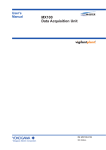
MI-2 MULTIPATH/TUNING INDICATOR
GENERAL DESCRIPTION
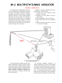
The Mclntosh MI-2 Multipath/Tuning Indicator is designed to be used with an FM tuner
to detect and display multipath reception.
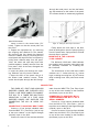
Multipath reception is the result of a reflected
signal arriving at the tuner antenna slightly
later than the direct signal. By rotating or
repositioning your FM antenna it is possible
to reduce the multipath reception. The MI-2
Multipath/Tuning Indicator makes it easy to
know when the FM antenna is oriented for
the best reception of any station.
DIRECT
SIGNAL
Multipath reception degrades FM tuner
performance in several ways:
1) Usually there is an increase in background noise level.
2) Distortion is often heard in the program signal.
3) Stereo separation may be reduced.
4) The stereo effect may be completely
lost.
5) Stereo indicators may fail to function,
or function erratically.
REFLECTED
SIGNALS
Figure 1. FM Tuner Antenna Receiving
Direct and Reflected Signals
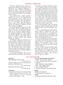
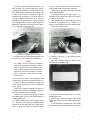
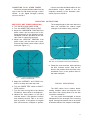
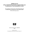
To show multipath reception the MI-2 displays instantaneous signal strength versus
frequency deviation. Signal strength is shown
as vertical deflection of the indicator display
beam. Frequency deviation is shown as horizontal deflection. Multipath reception appears as a peak or a valley in the MI-2 display. See Figure 2.
To overcome multipath reception it is
usually necessary to orient the tuner antenna
to receive the FM signal by only one predominant path. Rotating a directional antenna is
very effective at correcting multipath reception. In a metropolitan area where a simple
antenna such as a dipole is used repositioning the antenna will achieve the same result.
1
(2a)
(2 b)
(2c)
(2d)
Figure 2. Various Forms of Multipath Reception
As They Appear on the MI-2 Display Screen.
Such a change may be as little as a fraction
of a foot or as much as several feet.
The MI-2 is also a very effective tuning
indicator:
1) Signal strength is shown by the vertical
position of the display trace. The higher
the position of the trace the greater is
the signal strength.
2) Correct tuning occurs when the display
trace is centered horizontally on the
screen. Since the display trace effectively follows the tuner I.F. response
curve, centering the trace tunes the
detector to the center of the I.F. curve.
The Mclntosh MI-2 Multipath/Tuning Indicator is a versatile instrument. Its usefulness
has been extended to show other signal voltages. By turning the SCOPE TEST switch to
the L & R AUDIO position the MI-2 shows the
stereo or monaural character of the audio
signals).
2
1) A trace display along the L+R line will
occur with a monaural program source.
2) A trace display along the L - R line will
occur with a monaural program source
if the phase of one channel is reversed.
3) A vertical trace indicates that the program is being delivered to the left
channel only.
4) A horizontal trace indicates that the
program is being delivered to the right
channel only.
5) Operating the balance control on your
tuner-preamplifier or system preamplifier can change the slope angle of the
L+R or L - R display.
6) A stereo program will be a complex and
varying circular or elliptical display of
irregular outline that depends on channel separation or on the phase amplitude relation of the Left and Right
channel.
TECHNICAL DESCRIPTION
The MI-2 Multipath/Tuning Indicator is
essentially an oscilloscope using a three inch
cathode-ray tube. Adequate brightness is
assured by using a 1350 volt accelerating
voltage. To provide a sharp and well defined
trace, the MI-2 uses separate focus and astigmatism controls.
Two identical direct coupled push-pull
amplifiers are used in the horizontal and
vertical deflection circuits. Phase shift in
each amplifier is held to within a few degrees
from D.C. throughout the operating frequency range. Phase differences between
vertical and horizontal amplifiers are also
held to within a few degrees.
The high-voltage power supply uses a 6W4
tube rectifier. Two low-voltage supplies use
selenium rectifiers, two gas filled regulator
tubes and an electronic voltage regulator.
The operating voltages from these supplies
are carefully regulated over a wide range of
power line variations. This design feature
assures a steady indicator trace despite
changing line voltage.
For Multipath display the horizontal deflection voltage is obtained from the tuner
discriminator output ahead of the de-emphasis network. This voltage is proportional to
the frequency deviation of the FM transmission. The maximum width of the indicator
screen is designed to correspond to approximately plus and minus 75 kilocycle deviation
of the FM transmitter.
The horizontal multipath input is connected through the Deviation Input jack and
the Deviation (horizontal) calibration control.
For multipath display the vertical deflection voltage is obtained from the tuner Automatic Gain Control circuit at the input to the
first limiter. This voltage is proportional to FM
station's instantaneous signal strength. However the average proportionality is exponential. Because of the exponential characteristic, a weak station will produce adequate
vertical deflection. A powerful local station
should position the center of the indicator
trace about half to three quarters of an inch
below the top of the vertical scale.
The vertical Multipath Input is connected
through the Signal Strength Input and the
Signal Strength (vertical) Calibration Input
Control.
For L & R Audio display the horizontal deflection voltage is obtained from the right
channel output of a tuner, a preamplifier or
even a power amplifier. This deflection voltage is connected through the Right Audio
Input and the Right Gain Control.
For L & R Audio display the vertical deflection voltage is obtained from the left channel
output of a tuner, a preamplifier or a power
amplifier. This deflection voltage is connected through the Left Audio Input and the
Left Gain Control.
With a normal loudness monaural signal
both audio input controls are adjusted for
equal deflection of the display trace. At this
point the trace will lie on the L+R line if the
two signals are in phase or the L - R line if
they are 180° out of phase.
M I - 2 SPECIFICATIONS
Sensitivity
Signal Strength (Vertical) Input
0.37 Volts
Left Gain (Vertical) Input 0.37 Volts
Deviation (Horizontal) Input
0.27 Volts
Right Gain (Horizontal) Input
0.27 Volts
per Cm.
per Cm.
per Cm.
per Cm.
Dimensions
Front panel 155/8 inches x 51/8 inches; overall
depth of chassis behind front panel, 11½
inches; clearance in front of mounting
panel including knobs, 1 inch.
Tube and Semiconductor Complement
1—3RP1, 3 inch Cathode Ray tube.
4—6U8, Horizontal and Vertical Deflection
amplifiers
1—6U8, Electronic Voltage Regulator.
1-6W4, High Voltage Rectifier.
2 - O B 2 , Voltage Regulators.
6—Selenium Rectifiers, low-voltage supply.
Weight
Chassis only,22pounds.
In shipping carton, 29 pounds.
Finish
Anodized gold and black glass front panel.
3
Power Consumption
Fuse
1 Ampere SLO BLO
50 watts, 105 to 125 volts.
50 to 60 cycles.
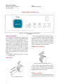
FRONT PANEL INFORMATION
Figure 3. MI-2 FM MULTIPATH/TUNING INDICATOR
Front Panel.
INDICATOR SCREEN
The screen is the face of a cathode ray
tube. Calibration marks are provided to allow
correct positioning of the indicator trace.
A correctly tuned station free of multipath distortion will appear as a smooth curve
centered on the indicator screen vertical
scale. The vertical line is marked to show the
relative strength of the FM signal. A strong
local signal should position the display
about ½ to ¾ inch from the top of the vertical
scale. The horizontal line is marked to show
deviation.
The two 45° sloped lines show L + R and
L - R information.
This control switches the indicator circuits
to show Multipath, Left and Right audio
signals or Test. The TEST position switches
the indicator trace to a single dot for adjustment of trace position, focus and intensity.
Different trace reference positions are necessary for multipath and L & R Audio.
HORIZONTAL POSITION
SCOPE TEST
Figure 5. HORIZONTAL POSITION Control.
This control moves the indicator trace to
the left or right. With the Scope Test switch
in TEST position, the trace dot can easily be
centered on the indicator screen.
Figure 4. SCOPE TEST Control.
4
VERTICAL POSITION
This control moves the indicator trace up
or down. With the Scope Test switch in TEST
FOCUS
Figure 6. VERTICAL POSITION Control.
position the indicator trace can be easily
moved to the correct vertical position. For
Multipath display the trace is positioned at
the bottom reference point (point A). For
audio indications the trace is positioned at
the center reference point (point B). This
shift in position occurs automatically as the
Scope Test Control is turned. An internal
adjustment labeled "L & R position" is
factory preset but can be read justed if needed.
Figure 8. FOCUS Control
This control adjusts the sharpness and
clarity of the indicator trace. Focus is easiest
with the Scope Test switch in TEST position.
INTENSITY
Figure 9. ON-OFF SWITCH PILOT LIGHT
Figure 7. INTENSITY Control.
This control adjusts the brightness of the
indicator trace. After the Intensity control
has been turned, the Focus control may have
to be readjusted for the best possible indicator trace.
BACK PANEL INFORMATION
Figure 10. MI-2 FM MULTIPATH/TUNING INDICATOR
Back Panel.
5
SIGNAL STRENGTH (VERTICAL)
MULTIPATH CONTROL
This Control adjusts the position of the
Multipath trace display along the vertical
scale of the indicator screen.
DEVIATION (HORIZONTAL)
MULTIPATH CONTROL
This control adjusts the maximum width
of the multipath trace display along the horizontal scale of the indicator screen.
LEFT GAIN (VERTICAL) AUDIO CONTROL
This control adjusts the maximum vertical
indicator trace deflection from a left channel
audio signal.
RIGHT GAIN (HORIZONTAL)
AUDIO CONTROL
This control adjusts the maximum horizontal indicator trace deflection from a right
channel audio signal.
SIGNAL STRENGTH INPUT (TP I)
This input connects to a Mclntosh tuner
Test Point 1, which supplys a voltage proportional to Signal Strength for vertical deflection of the indicator trace.
DEVIATION INPUT (TP 2)
This input connects to a Mclntosh tuner
Test Point 2, which supplys a voltage proportional to deviation of the FM transmission for
horizontal deflection of the indicator trace.
LEFT AUDIO INPUT
This input connects to the left output of a
tuner, preamplifier or power amplifier. The
left channel audio signal voltage causes ver-
tical deflection of the indicator trace. This
input jack is in parallel with the left audio
output jack.
LEFT AUDIO OUTPUT
This output jack is in parallel with the left
Audio input jack. This parallel connection
makes it convenient for connecting a preamplifier or tuner output to both the MI-2 and
the power amplifier.
RIGHT AUDIO INPUT
This input connects to the Right output of
a tuner, preamplifier or power amplifier. The
right channel audio signal voltage causes a
horizontal deflection of the indicator trace.
This input jack is in parallel with the right
audio output jack.
RIGHT AUDIO OUTPUT
This output jack is in parallel with the
Right audio input jack. This parallel connection makes it convenient for connecting a
preamplifier or tuner output to both the MI-2
and the power amplifier.
1A SLO BLO
A 1 ampere SLO-BLO fuse protects the
MI-2 indicator circuits. This fuse does not
protect additional equipment connected to
the back panel AC outlet.
350 WATTS AC OUTLET
A 117 volt AC outlet is provided for extra
equipment drawing as much as 350 watts
power. The outlet is not fused and is on whenever the MI-2 power cord is connected to an
AC outlet.
INSTALLATION
The Mclntosh MI-2 Indicator may be installed on a table, on a shelf, in a custom
built-in cabinet, or in a professional equipment rack. The MI-2 may be mounted directly above a tuner or at either side, whichever is more convenient. For best appearance in an open installation, it is suggested
that you mount the MI-2 in the attractive
Mclntosh Model L10W and L10W0 finished
wood cabinet.
6
The MI-2 may be mounted in panels up to
1 inch in thickness. If the panel is at least
¼ inch or more in thickness, the indicator
will be adequately supported by the four front
panel mounting screws. In cases where the
front panel may be thin or flexible, a shelf is
necessary to support the weight of the indicator. A shelf should not be required when
the MI-2 is mounted in a metal rack panel.
An MI-2 cabinet installation should provide at least 13¾ inches behind the mounting panel for clearance of leads and connectors. Allow inside dimensions of at least 16½
inches in width and 5 inches in height for
adequate air circulation. The back panel of
the MI-2 cabinet should be left as open as
possible for best ventilation. Avoid mounting
the indicator directly over a power amplifier.
Adequate ventilation will insure your indicator a long and trouble-free life.
Figure 11. Positioning the Mounting
Template Over Proposed Area to be Cutout.
1a. Position the MI-2 mounting template over
the area to be cut out for the installation.
NOTE
The design of the mounting template
allows you to position or locate the cutout
either from the front or the back of the
panel to which the MI-2 is to be mounted.
If the MI-2 is to rest on a shelf it is necessary to locate the cutout from the back
of the panel.
1b. If the MI-2 is to be located from the back
of the panel, the following steps will help you.
Scribe a vertical centerline through the
exact center of the cutout area on the back
of the panel.
Place the template against the back of
the panel and match the template centerline
with the scribed cutout centerline.
If the MI-2 is to rest on a shelf then make
sure the bottom of the mounting template is
touching the shelf.
1c. Before marking the two locating holes
("c" holes on the mounting template) take
special note that there are two small diameter " c " holes and two 3 / 16 " diameter larger
holes. In order to have the MI-2 rest on the
shelf follow these instructions carefully.
Mark with a pointed instrument the two
small diameter holes.
Drill these two holes through with a 3/16"
diameter drill making sure they are perpendicular to the panel.
Now position the template on the front of
the panel by aligning the 3 / 16 " diameter " c "
holes of the template with the drilled holes.
Proceed to Step 2 now.
Figure 12. Marking the Cutout Indications.
2. Mark the " A " and " B " drill holes and the
four corners.
Join the corners using the edge of the
template as a straight edge.
Figure 13. MI-2 Installation Cutout.
3. Drill the mounting holes and cut out the
rectangular hole.
4. Secure the mounting strips to the panel
using two of the four flat head screws provided.
In the hardware package are 4 flat head
screws and 8 fillister-head screws for varying
7
through the wood panel, and into the fasten
ing strip attached to the inside of the panel
The screws should be moderately tightened.
Figure 14. Securing Mounting Strips To
Installation Cutout.
panel thicknesses.
Insert a screw in the center holes ( " B "
holes). Tighten so that the screw pulls into
the wood.
5. Prepare the equipment by: (A) removing
the shipping skid attached to the chassis,
(B) removing the four plastic feet fastened
under the chassis, and (C) removing the two
metal panel end caps from the front panel by
pulling them sidewise away from the panel.
Note, the metal end caps may have been
packed separate, already removed from the
front panel: if this is the case, disregard this
last instruction.)
6. Insert the power cord through the opening. Slide the unit fully into the cabinet.
7. Secure the MI-2 to the panel using 4 of
the fillister head machine screws. These
screws should pass through the MI-2 flange,
Figure 15. Fitting the End Caps to the Panel.
Finally attach the end caps to the MI-2
panel by sliding them onto the pins projecting
from the panel ends. Spring tension will hold
the end caps in position.
MOUNTING IN THE L10W AND
L10W0 CABINET
The Mclntosh L10W and L10W0 cabinets
are supplied with complete instructions and
all necessary hardware for installing the
MI-2 Indicator.
The dimensions of the L10W and L10W0
cabinets are 17 inches wide by 65/8 inches
high, including mounting feet, by 14 3 / 8 inches
deep including tuner front panel and control
knobs.
CONNECTING
TWO PAIRS OF 3 FOOT LONG LOW-LOSS
SHIELDED CABLES ARE SUPPLIED WITH
THE MI-2. USE THESE CABLES TO CONNECT
THE MI-2 TO A TUNER FOR MULTIPATH
INDICATION. A PAIR OF 6 FOOT LONG
SHIELDED CABLES ARE SUPPLIED FOR
CONNECTING THE MI-2 IN AUDIO CIRCUITS.
CONNECTING TO MclNTOSH MR67 TUNER
Connect a 3 foot low-loss shielded cable
from the MR67 TP1 (Test Point 1 jack on top
of the tuner chassis to the Signal Strength
(vertical) Input on the MI-2.
Connect a second 3 foot low-loss shielded
8
cable from the MR67 TP2 (Test Point 2 jack
on top of the tuner chassis) to the Deviation
(horizontal) Input on the MI-2.
CONNECTING TO MclNTOSH MX 110
TUNER-PREAMPLIFIER WITH Z OR X
SERIAL NUMBERS
Connect a 3 foot low-loss shielded cable
from the MX110 TP1 (Test Point 1 jack on
top of the tuner chassis) to the Signal Strength
(vertical) Input on the MI-2.
Connect a second 3 foot low-loss shielded
cable from the MX110 TP2 (Test Point 2 jack
on top of the tuner chassis) to the Deviation
(horizontal) Input on the MI-2.
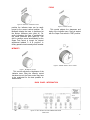
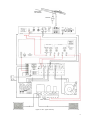
DIRECTIONAL
FM ANTENNA
ROTATOR
TO TP I
TO II7V
AC OUTLET
STEREO
POWER AMPLIFIER
Figure 16. MI-2 Typical Hook-Up.
9
CONNECTING TO MclNTOSH MX110
TUNER-PREAMPLIFIER WITH M
SERIAL NUMBERS
Remove capacitor C130 (.005 MF) connected between the test point and ground.
Solder the center lead of a 1 foot low-loss
shielded cable to the junction point of R139
(10K) and C125 (.1 MFD). Solder the outer
shield of the cable to the tuner chassis
ground. Use one of the 1 foot long low-loss
shielded cables, stripped and tinned on one
end, (female jacks on the other end) supplied with the MI-2.
Use a connector with male plugs to connect the soldered in cable from the tuner to
the Deviation (horizontal) Input on the MI-2.
Connect a 3 foot low-loss shielded cable
from the test point (on top of tuner chassis)
to the Signal Strength (vertical) Input on the
MI-2.
CONNECTING TO MclNTOSH MR65B
TUNER
Remove capacitor C27 (.005 MFD) connected between TP1 and chassis ground.
MR65B tuners serial numbers 300U0 and
above do not have this capacitor.
Connect a 3 foot low-loss shielded cable
from the MR65B TP1 (Test Point 1 on tuner
back panel) to the Signal Strength (vertical)
Input on MI-2.
Connect a 3 foot long low-loss shielded
cable from the MR65B TP2 (Test Point 2 on
top of tuner chassis) to the Deviation (horizontal) Input on the MI-2.
CONNECTING TO MclNTOSH MR65 and 65A
Remove capacitor C31 (.005 MFD) connected between the test point and ground.
Connect a 3 foot low-loss shielded cable
from the MR65A Test Point (jack on top of
tuner chassis) to the Signal Strength (vertical) input on the MI-2.
Connect a 3 foot low-loss shielded cable
from the MR65A MPX out jack on the tuner
back panel to the Deviation (horizontal) Input
on the MI-2.
If an external multiplex adapter is being
used with the MR65, a "Y" connector will be
needed in the MPX output jack. This allows
both the MPX adapter and the lead to the
MI-2 to be connected.
10
CONNECTING TO MclNTOSH MR66 TUNER
Remove capacitor C125 (.005 MFD) connected between the test point and ground.
Connect a 3 foot low-loss shielded cable
from the TEST POINT (on top of tuner chassis) to the Signal Strength (vertical) Input on
the MI-2.
Connect a 3 foot low-loss shielded cable
from the FM Multiplex output jack on the
tuner back panel to the Deviation (horizontal)
Input on the MI-2.
CONNECTING TO MclNTOSH MR55A TUNER
Remove the feed-through capacitor L43
(1000 MMF) connected to TP-1. This capacitor can best be removed by unsoldering.
Solder the center lead of a 1 foot low-loss
shielded cable to the Test Point end of R27
(100K resistor). Solder the outer shield of
the cable to the chassis where the feedthrough capacitor was soldered. The cable
can feed through the hole in the chassis
where the capacitor was soldered. Use one
of the 1 foot long low-loss shielded cables,
stripped and tinned on one end, (female
jacks on the other end) supplied with the
MI-2.
Use a connector with male plugs to connect the soldered-in cable to the Signal
Strength (vertical) Input on the MI-2.
Connect a 3 foot low-loss shielded cable
from the multi-out (multiplex output) jack on
the tuner to the Deviation (horizontal) Input.
If a multiplex adapter is being used with
the MR55A, a "Y" connector will be needed
in the MULTI-OUT Jack. This allows both the
multiplex adapter and the lead to the MI-2
to be connected.
CONNECTING TO MclNTOSH MR55 TUNER
Solder a wire across resistor R62 (1 meg)
connected to the test point on the tuner
chassis.
Connect a 3 foot low-loss shielded cable
from the test point on top of the tuner chassis
to the Signal Strength (vertical) Input on
the MI-2.
Connect a 3 foot low-loss shielded cable
from the MULTIPLEX OUTPUT jack on the
tuner to the Deviation (horizontal) Input on
the MI-2.
CONNECTING TO ALL OTHER TUNERS
Connect a low-loss shielded cable from the
input to the first FM limiter through a 100 K
resistor, to the Signal Strength (vertical)
Input on the MI-2.
Connect a low-loss shielded cable from the
discriminator output (ahead of the deemphasis network) to the Deviation (horizontal) Input on the MI-2.
OPERATING INSTRUCTIONS
MULTIPATH AND TUNING INDICATION
1. Turn the MI-2 power switch to ON.
2. Turn the SCOPE TEST switch to TEST.
3. Adjust the HORIZONTAL POSITION front
panel control until the trace dot is centered horizontally on the indicator screen.
Calibration lines are provided on the indicator face for centering purposes.
4. Adjust the VERTICAL POSITION front
panel control until the trace dot is positioned at the bottom center of the vertical
scale (See Figure 17.)
The average height of the trace above the
base line indicates the relative signal
strength of the station being received.
Figure 18. Uniform and Relatively Smooth Trace
With Little or No Multipath Present (80% Modulation).
9. Rotate the tuner antenna, while watching
the MI-2 Indicator screen. Stop the antenna in the position where the trace is the
smoothest curve. In this position there is
the least multipath.
Figure 17. Trace Dot Positioned at Bottom
Center of Vertical Scale.
5. Adjust the INTENSITY and FOCUS controls for a sharp and clear trace dot.
TYPICAL INDICATIONS
6. Turn the SCOPE TEST switch to MULTIPATH position.
7. Turn the tuner tuning dial to the desired
FM station, either stereo or monophonic.
8. Observe the trace pattern on the MI-2
Indicator screen. If the pattern is uniform
and relatively smooth, little or no multipath is present. If the pattern is irregular
with vertical traces, multipath is present.
The 19KC carrier from a station broadcasting multiplex stereo will keep the Indicator trace from closing down to a dot with
no station modulation.
You may notice that Multipath is almost
independent of the strength of the incoming
signal. Strong local stations can be as critical
as distant stations with respect to Multipath.
11
Figure 19. Irregular Pattern With Vertical Traces
Indicating The Presence of Multipath.
2. Adjust the SIGNAL STRENGTH (vertical.
Multipath control on the back panel until
the pattern on the indicator screen is about
¾ inch from the top of the vertical scale.
The 19KC carrier from a station broadcasting multiplex
stereo will keep the Indicator trace from closing down to
a dot with no station modulation.
Figure 20. 19KC Pilot.
SIGNAL STRENGTH MULTIPATH CONTROL
1. Tune in a relatively strong local signal
with the antenna positioned for minimum
multipath.
12
DEVIATION MULTIPATH CONTROL
1. Tune in a relatively strong local signal
with the antenna positioned for maximum
multipath.
2. Adjust the DEVIATION (horizontal) Multipath control until the horizontal pattern
(loudest signal from the station does not
extend over the ends of the horizontal
scale of the indicator screen.
L & R AUDIO INDICATIONS
1. Turn the MI-2 Power switch to ON.
2. Turn the SCOPE TEST switch to TEST.
3. Adjust the HORIZONTAL POSITION front
panel control until the trace dot is cen-
tered horizontally on the Indicator screen.
Calibration lines are provided on the Indicator face for centering purposes.
4. Adjust the vertical position control until
the trace dot is positioned at the bottom
of the center vertical scale.
Figure 2 1 . Trace Dot Positioned at Center of Screen.
5. Adjust the INTENSITY and FOCUS controls for a sharp and clear trace dot.
6. Turn the SCOPE TEST switch to L & R
Audio.
7. Set the tuner to an FM Station broadcasting a monophonic program.
8. Adjust the LEFT GAIN and RIGHT GAIN
controls on the MI-2 until the incoming
program causes the Indicator trace to
align directly over the L + R Line.
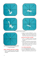
RIGHT CHANNEL
ONLY
(22b)
LEFT CHANNEL
ONLY
(22a)
STEREO-LEFT CHANNEL
NOT EQUAL TO RIGHT
CHANNEL
(22c)
STEREO-LEFT CHANNEL EQUAL TO
RIGHT CHANNEL
(22d)
Figure 22. Audio Presentations.
13
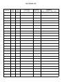
FM STATION LOG
STATION
14
DIAL
FREQ.
LOG
SCALE
LOCATION
CITY, STATE
ANTENNA
DIRECTION
REMARKS
MONO—STEREO—TIME—DATE
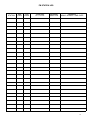
FM STATION LOG
STATION
DIAL
FREQ.
LOG
SCALE
LOCATION
CITY, STATE
ANTENNA
DIRECTION
REMARKS
MONO—STEREO—TIME—DATE
15
Your MI-2 will give you many years of pleasant and satisfactory performance. If you have any questions concerning the operation or maintenance of this tuner please contact:
Customer Service
Mclntosh Laboratory Inc.
2 Chambers Street
Binghamton, New York
Our telephone number is 723-5491.
The direct dial area code is 607.
GUARANTEE
Mclntosh Laboratory Incorporated guarantees this equipment to perform as advertised. We also guarantee the mechanical and
electrical workmanship and components of
this equipment to be free of defects for a
period of 90 days from date of purchase.
This guarantee does not extend to components damaged by improper use nor does it
extend to transportation to and from the
factory.
3-YEAR FACTORY SERVICE CONTRACT
An application for a FREE 3-YEAR FACTORY SERVICE CONTRACT is included in
the pocket in the back cover of this manual.
The FREE 3-YEAR FACTORY SERVICE CONTRACT will be issued by Mclntosh Laboratory
upon receipt of the completely filled out
application form. If the application is not
mailed to Mclntosh Laboratory, only the
services offered under the standard 90-day
guarantee will apply on this equipment.
TAKE ADVANTAGE OF 3 YEARS OF FREE
FACTORY SERVICE BY FILLING IN THE
APPLICATION NOW.
In Canada: manufactured under license by:
McCurdy Radio Industries, Ltd.
22 Front Street West
Toronto, Canada
Design subject to change without notice
16
LABORATORY
2 CHAMBERS STREET, BINGHAMTON, N. Y.
Made in U.S.A.
P h o n e - A r e a Code 607-723-5491
INC.