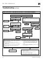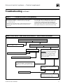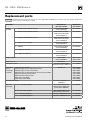
1
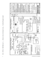
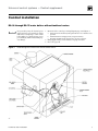
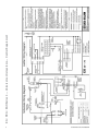
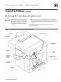
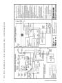
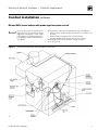
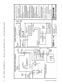
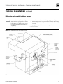
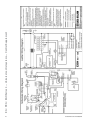
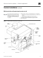
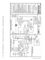
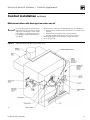
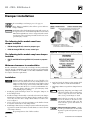
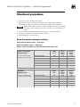
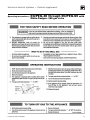
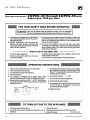
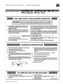
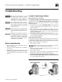
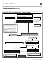
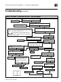
EG • PEG • EGH
Gas-Fired Boilers – Series 4
Control supplement – Universal control systems
For additional information, refer to . . .
EG•PEG•EGH Boiler manual
for Natural or Propane gas
(tankless heater application optional)
This supplement must only be used by a qualified heating installer/service technician. Before installing, read all
instructions, including this supplement, the boiler manual and any related documents. Perform steps in the order given.
Failure to comply could result in severe personal injury, death or substantial property damage.
Part Number 550-110-646/0607
EG • PEG • EGH Series 4
Please read this page first!
Hazard definitions
The following defined terms are used throughout these instructions to bring attention to the
presence of hazards of various risk levels or to important information concerning the life of
the product.
Indicates presence of hazards that will cause severe personal injury, death or
substantial property damage.
Indicates presence of hazards that can cause severe personal injury, death or
substantial property damage.
Indicates presence of hazards that will or can cause minor personal injury or
property damage.
Indicates special instructions on installation, operation or maintenance that are
important but not related to personal injury or property damage.
Note to the installer
Controls must only be installed by a Weil-McLain distributor or other qualified
installer/service technician in accordance with this Supplement and all applicable
codes and requirements of the authority having jurisdiction. Read this Control
Supplement completely before beginning the installation. If the information
in this Supplement is not followed exactly, a fire, explosion, carbon monoxide
emission or other hazardous conditions can result, causing severe personal injury,
death or substantial property damage.
This system is used on gas-fired boilers without vent dampers as shipped from
the factory. This system is not offered for retrofit. Any attempt to apply the system
components to boilers shipped for use with a different control system will not
be covered under boiler warranty and can cause severe personal injury, death or
substantial property damage.
When calling or writing about the boiler, please have the boiler model number
from the boiler rating label and the CP number from the boiler jacket.
Part Number 550-110-646/0607
Universal control systems — Control supplement
Table of contents
Hazard definitions and Note to the installer.....................................................................................2
Control installation — EG-30 through EG-75 water boilers without tankless heaters............. 4-5
Control installation — EG-30 through EG-75 water boilers with tankless heaters................... 6-7
Control installation — EG and PEG steam boilers with probe-type low water cutoff.............. 8-9
Control installation — EG steam boilers with float-type low water cutoff............................. 10-11
Control installation — EGH water boilers without tankless heaters...................................... 12-13
Control installation — EGH water boilers with tankless heaters............................................ 14-15
Control installation — EGH steam boilers with probe-type low water cut-off...................... 16-17
Control installation — EGH steam boilers with float-type low water cut-off........................ 18-19
Damper installation...........................................................................................................................20
Checkout procedure.........................................................................................................................21
Operating instructions................................................................................................................ 22-26
Troubleshooting........................................................................................................................... 27-31
Replacement parts............................................................................................................................32
Part Number 550-110-646/0607
Part Number 550-110-646/0607
EG • PEG • EGH Series 4 — Universal control systems — Control Supplement
Universal control systems — Control supplement
Control installation
EG-30 through EG-75 water boilers without tankless heaters
For your safety, turn off electrical power
supply and turn off external gas supply
valve before attempting to work on the
boiler. Failure to comply can cause severe
personal injury, death or substantial property damage.
Figure 1
1. Mount and wire controls per wiring diagram, page 4, and Figure 1.
a. Attach junction box inside left jacket panel with #8-32 x ½” machine screws
provided.
b. Install transformer with plug-in relay receptacle and relay.
c. Operating and limit circuit wiring must be 18 gauge or heavier.
2. Bring supply wiring to boiler. Must be 14 gauge or heavier.
3. Proceed to page 20.
EG-30 through EG-75 water boilers without tankless heaters
Part Number 550-110-646/0607
Part Number 550-110-646/0607
EG • PEG • EGH Series 4 — Universal control systems — Control Supplement
Universal control systems — Control supplement
Control installation
continued
EG-30 through EG-75 water boilers with tankless heaters
For your safety, turn off electrical power
supply and turn off external gas supply
valve before attempting to work on the
boiler. Failure to comply can cause severe
personal injury, death or substantial property damage.
Figure 2
1. Mount and wire controls per wiring diagram, page 6, and Figure 2.
a. Install combination limit control and relay in tapping. See Boiler Manual
control tapping table. Operating and limit circuit wiring must be 14 gauge
or heavier.
2. Bring supply wiring to boiler. Must be 14 gauge or heavier.
3. Proceed to page 20.
EG-30 through EG-75 water boilers with tankless heaters
Part Number 550-110-646/0607
Part Number 550-110-646/0607
EG • PEG • EGH Series 4 — Universal control systems — Control Supplement
Universal control systems — Control supplement
Control installation
continued
EG and PEG steam boilers with probe-type low water cut-off
For your safety, turn off electrical power
supply and turn off external gas supply
valve before attempting to work on the
boiler. Failure to comply can cause severe
personal injury, death or substantial property damage.
Figure 3
1. Mount and wire controls per wiring diagram, page 8, and Figure 3.
a. Attach junction box inside left jacket panel with #8-32 x ½” machine screws
provided.
b. Install transformer with plug-in relay receptacle and relay.
c. Operating and limit circuit wiring must be 18 gauge or heavier.
2. Bring supply wiring to boiler. Must be 14 gauge or heavier.
3. Proceed to page 20.
EG and PEG steam boilers with probe-type low water cut-off
Part Number 550-110-646/0607
10
Part Number 550-110-646/0607
EG • PEG • EGH Series 4 — Universal control systems — Control Supplement
Universal control systems — Control supplement
Control installation
continued
EG steam boilers with float-type low water cut-off
For your safety, turn off electrical power
supply and turn off external gas supply
valve before attempting to work on the
boiler. Failure to comply can cause severe
personal injury, death or substantial property damage.
Figure 4
1. Mount and wire controls per wiring diagram, page 10, and Figure 4.
a. Attach junction box inside left jacket panel with #8-32 x ½” machine screws
provided.
b. Install transformer with plug-in relay receptacle and relay.
c. Operating and limit circuit wiring must be 18 gauge or heavier.
2. Bring supply wiring to boiler. Must be 14 gauge or heavier.
3. Proceed to page 20.
EG steam boilers with float-type low water cut-off
Part Number 550-110-646/0607
11
12
Part Number 550-110-646/0607
EG • PEG • EGH Series 4 — Universal control systems — Control Supplement
Universal control systems — Control supplement
Control installation
continued
EGH water boilers without tankless heaters
For your safety, turn off electrical power
supply and turn off external gas supply
valve before attempting to work on the
boiler. Failure to comply can cause severe
personal injury, death or substantial property damage.
Figure 5
1. Mount and wire controls per wiring diagram, page 12, and Figure 5.
a. Attach junction box inside left jacket panel with #8-32 x ½” machine screws
provided.
b. Install transformer with plug-in relay receptacle and relay.
c. Operating and limit circuit wiring must be 18 gauge or heavier.
2. Bring supply wiring to boiler. Must be 14 gauge or heavier.
3. Proceed to page 20.
EGH water boilers without tankless heaters
Part Number 550-110-646/0607
13
14
Part Number 550-110-646/0607
EG • PEG • EGH Series 4 — Universal control systems — Control Supplement
Universal control systems — Control supplement
Control installation
continued
EGH water boilers with tankless heaters
For your safety, turn off electrical power
supply and turn off external gas supply
valve before attempting to work on the
boiler. Failure to comply can cause severe
personal injury, death or substantial property damage.
Figure 6
1. Mount and wire controls per wiring diagram, page 14, and Figure 6.
a. Install combination limit control and relay in tapping. See Boiler Manual
control tapping table. Operating and limit circuit wiring must be 14 gauge
or heavier.
2. Bring supply wiring to boiler. Must be 14 gauge or heavier.
3. Proceed to page 20.
EGH water boilers with tankless heaters
Part Number 550-110-646/0607
15
16
Part Number 550-110-646/0607
EG • PEG • EGH Series 4 — Universal control systems — Control Supplement
Universal control systems — Control supplement
Control installation
continued
EGH steam boilers with probe-type low water cut-off
For your safety, turn off electrical power
supply and turn off external gas supply
valve before attempting to work on the
boiler. Failure to comply can cause severe
personal injury, death or substantial property damage.
Figure 7
1. Mount and wire controls per wiring diagram, page 16, and Figure 7.
a. Attach junction box inside left jacket panel with #8-32 x ½” machine screws
provided.
b. Install transformer with plug-in relay receptacle and relay.
c. Operating and limit circuit wiring must be 18 gauge or heavier.
2. Bring supply wiring to boiler. Must be 14 gauge or heavier.
3. Proceed to page 20.
EGH steam boilers with probe-type low water cut-off
Part Number 550-110-646/0607
17
18
Part Number 550-110-646/0607
EG • PEG • EGH Series 4 — Universal control systems — Control Supplement
Universal control systems — Control supplement
Control installation
continued
EGH steam boilers with float-type low water cut-off
For your safety, turn off electrical power
supply and turn off external gas supply
valve before attempting to work on the
boiler. Failure to comply can cause severe
personal injury, death or substantial property damage.
Figure 8
1. Mount and wire controls per wiring diagram, page 18, and Figure 8.
a. Attach junction box inside left jacket panel with #8-32 x ½” machine screws
provided.
b. Install transformer with plug-in relay receptacle and relay.
c. Operating and limit circuit wiring must be 18 gauge or heavier.
2. Bring supply wiring to boiler. Must be 14 gauge or heavier.
3. Proceed to page 20.
EGH steam boilers with float-type low water cut-off
Part Number 550-110-646/0607
19
EG • PEG • EGH Series 4
Damper installation
If not installing a vent damper, proceed to page 21.
Figure 9 Vent damper assemblies
Once damper is installed, boiler will not operate without a
damper installed.
Only dampers listed in the Replacement parts table on page 32 are approved for use on EG-30 through EG-75 Series 4 and
PEG-30 through PEG-65 Series 4 using Universal Control
Systems. Any other vent damper installed could cause severe
personal injury or death.
The following boiler models must have
damper installed:
• EG-30 through EG-65, natural or propane gas.
•
PEG-30 through PEG-65, steam, natural gas.
Figure 10 Vent damper harness plug warning label
The following boiler models may have damper
installed:
•
EG-75 and EGH-85 through EGH-125, natural or propane
gas.
Minimum clearances to combustibles
Provide a minimum of 6” between the vent damper and any combustible
material. (Provide a minimum of 46” between jacket top and combustible
ceiling for EG/PEG, or 24” for EGH.) See EG • PEG • EGH Boiler manual
for complete clearance requirements.
Installation
1.
2.
3.
4.
Damper must be installed directly on top of draft hood so
that it serves only that boiler. Do not modify draft hood or
damper, or make another connection between draft hood and
damper or boiler except as noted below. This will void CSA
certification and will not be covered by Weil-McLain warranty. Any changes will cause severe personal injury, death,
or substantial property damage.
Install plug (packed in damper carton of 4” through 8” dampers) in
hole in damper blade.
Install vent damper horizontally or vertically as shown in vent damper
manufacturer’s instructions. Vent damper must be installed so that it
serves only one boiler and so damper blade indicator is visible to the
user. See Figure 9.
Screws or rivets used to secure the vent damper to the draft hood must
not interfere with rotation of the damper blade.
Install damper harness between damper actuator and knockout in jacket
top panel. Use strain relief connectors and locknuts to secure both ends
of the damper harness.
Keep wiring harness clear of all hot surfaces.
20
5. Read and apply the harness plug warning label
(Figure 10) so that it is visible after installation.
6. Plug damper harness receptacle into damper harness
plug.
Bypassing (jumpering) vent damper will
cause flue products such as carbon monoxide to escape into the house. This will
cause severe personal injury or death.
After boiler has operated once, if either
end of the harness is disconnected, the
system safety shutdown will occur. The
boiler will not operate until harness is
reconnected.
Effikal or Field Controls damper — Damper hold open switch must be in “Automatic
Operation” position for system to operate
properly.
Part Number 550-110-646/0607
Universal control systems — Control supplement
Checkout procedure
1. See pages 22–26 for “Operating instructions.”
2. Raise room thermostat to call for heat. Damper actuator will slowly open damper.
3. When damper is fully open, main gas valve will open and main burners will ignite.
Damper must be fully open before main burners light. If damper does not fully
open, flue products will escape into house, causing severe personal injury or
death.
4. Lower thermostat setting. Main burner flames will go out, then damper will close.
5. Repeat steps 1 through 3 several times to verify operation.
6. Return thermostat to normal setting.
Room thermostat anticipator settings
Water without tankless heater — 0.40 amps
Water with tankless heater — 0.20 amps
Steam — Select based on gas valve and damper. See table below.
Boilers with
United Technologies
Ignition control
Gas valve
(control load of 0.10 amps is
included in the values at right)
Without
damper
(amps)
With
Effikal
damper
(amps)
With
Johnson
damper
(amps)
Honeywell VR8200
0.60
0.70
0.80
Honeywell VR8300
0.80
0.90
1.00
Robertshaw 7200ER
0.50
0.60
0.70
Robertshaw 7000ERHC
0.80
0.90
1.00
White-Rodgers 36E
0.40
0.50
0.60
White-Rodgers 36C
0.70
0.80
0.90
Without
damper
(amps)
With
Effikal
damper
(amps)
With
Johnson
damper
(amps)
Boilers with
Honeywell
Ignition control
Gas valve
(control load of 0.20 amps is
included in the values at right)
Honeywell VR8200
0.70
0.80
0.90
Honeywell VR8300
0.90
1.00
1.10
Robertshaw 7200ER
0.60
0.70
0.80
Robertshaw 7000ERHC
0.90
1.00
1.10
White-Rodgers 36E
0.50
0.60
0.70
White-Rodgers 36C
0.80
0.90
1.00
Part Number 550-110-646/0607
21
EG • PEG • EGH Series 4
EG and PEG with
Operating instructions –
22
Honeywell VR8204/VR8304 gas valve
Part Number 550-110-646/0607
Universal control systems — Control supplement
EG/PEG-30 through EG/PEG-50 with
Operating instructions –
Part Number 550-110-646/0607
White-Rodgers 36E gas valve
23
EG • PEG • EGH Series 4
EG/PEG-30 through EG/PEG-50 with
Operating instructions –
24
Robertshaw 7200 gas valve
Part Number 550-110-646/0607
Universal control systems — Control supplement
EG/PEG-55, EG/PEG-65, EG-75 with
Operating instructions –
Part Number 550-110-646/0607
White-Rodgers 36C gas valve
25
EG • PEG • EGH Series 4
EGH with
Operating instructions –
26
Robertshaw 7000DERHC gas valve
Part Number 550-110-646/0607
Universal control systems — Control supplement
Troubleshooting
Burner access panel must be in position during boiler operation to prevent
momentary flame rollout on ignition of
main flame. Severe personal injury or
substantial property damage will result.
Never jumper (bypass) any device except for momentary testing as outlined
in Troubleshooting Charts. Substantial
property damage and/or severe personal
injury could occur.
Label all wires prior to disconnection
when servicing controls. Wiring errors
can cause improper and dangerous operation.
Verify proper operation after servicing. See
vent damper manufacturer’s instructions
packed with vent damper for additional
information. Failure to comply could
result in severe personal injury, death or
substantial property damage.
Before troubleshooting
1. Have a voltmeter that can check 120 VAC, 24 VAC,
and a continuity tester.
2. Check for 120 VAC (minimum 102 to maximum
132) to boiler.
3. Make sure thermostat is calling for heat and contacts
(including appropriate zone controls) are closed.
Check for 24VAC between thermostat wire nuts and
ground.
In event of vent damper failure:
Effikal or Field Controls vent damper
If troubleshooting chart recommends replacing actuator and actuator is
not immediately available, damper blade can be fixed in an open position
to allow boiler operation. Manually turning blade can cause actuator
damage. Follow these instructions only in case of no heat or damper
actuator malfunction.
1. Move damper service switch to Hold Damper Open position. Apply call
for heat to boiler. Damper blade should then rotate to open position
and boiler will fire.
2. If step 1 does not open damper, manually rotate damper blade to open
position using wrench or pliers on flat shaft between damper and actuator. Boiler will fire. Verify that damper service switch is in Hold Damper
Open position (Figure 11).
3. Do not leave vent damper permanently in this position. Replace actuator immediately. If vent damper is left in open position, boiler will not
operate at published efficiencies.
Johnson Controls vent damper
If troubleshooting chart recommends replacing actuator and actuator is
not immediately available, damper blade can be fixed in an open position
to allow boiler operation. Follow these instructions only in case of no heat
or damper actuator malfunction. See Figure 11.
1. Turn off power to boiler.
2.
3.
4.
5.
Failure to turn off power to boiler can result in severe personal
injury, death or substantial property damage.
Refer to vent damper manufacturer’s instructions for procedure to fix
vent damper in open position.
Turn on power to boiler.
Using wrench or pliers on flat shaft section, manually rotate damper
blade until green light turns on. Boiler will fire (Figure 11).
Do not leave vent damper permanently in this position. Replace
actuator immediately. If vent damper is left in open position, boiler will
not operate at published efficiencies.
Figure 11 Manually opening vent damper
Part Number 550-110-646/0607
27
EG • PEG • EGH Series 4
Troubleshooting
continued
CHART 1: NO SPARK — System does not work — Without vent damper
VISUALLY CHECK - is ground wire connected from
“GND (Burner)” to ignition control mounting screw;
and ground wire connected from transformer
Terminal “C” to case ground?
Correct by making connections.
Is the vent damper
plug in place?
Yes
No
No
Yes
Is 24VAC present across Terminals 24V & 24V(GND)?
No
Yes
Check for open thermostat or circulator relay
(where used) or check for loose wire connections, defective spill switch or rollout
thermal fuse element, or open LWCO or limit
contacts.
Replace damper
plug and retest.
If LWCO, spill switch or rollout
thermal fuse element contacts
are open, determine cause and correct condition. Failure to do so will cause severe personal injury, death, or substantial property
damage.
Open thermostat contacts for 15 seconds. Close thermostat contacts - is 24 VAC across terminals PV & MV/PV?
Replace ignition control.
No
Yes
Turn OFF supply voltage.
Check spark wire. Is it securely connected
to spark transformer?
Securely connect, then turn ON supply voltage and re-test.
No
Yes
Is condition of spark wire good (not cut,
brittle, burned, or cracked)?
Replace pilot assembly.
No
Yes
Is spark electrode ceramic cracked?
Is spark gap 0.125” and located in pilot gas steam?
No
No
Yes
Yes
Replace pilot assembly, turn ON supply
voltage, operate system several complete
heat cycles.
28
Replace pilot assembly, turn ON supply
voltage, operate system several complete
heat cycles.
Replace ignition control.
Part Number 550-110-646/0607
Universal control systems — Control supplement
Troubleshooting
continued
CHART 2: NO SPARK — System does not work — With vent damper
Is damper harness securely plugged in at both
ends?
Secure connections.
No
Yes
Is 24VAC present across terminals C and Y on
transformer?
Check for loose wire connections
or bad relay on transformer.
No
Yes
Is 24VAC present across terminal C and yellow wire
between damper connector and rollout thermal fuse
element?
Check for open thermostat or circ. relay (where used) or check for
loose wire connections, defective spill switch or rollout thermal fuse
element, or open LWCO or high limit contacts.
If LWCO, spill switch or rollout thermal fuse element
contacts are open, determine cause and correct
condition. Failure to do so will cause severe personal injury, death,
or substantial property damage.
Yes
No
Is damper rotated open?
Check for out of round stack section.
Does motor rotate open?
Replace actuator.
No
Check continuity of each wire in wiring
harness to damper. Does continuity exist
for each wire?
Is 24VAC present at Terminals
PV and MV/PV?
Yes
Turn OFF supply voltage.
Check spark wire. Is it securely
connected to ignition control?
Securely connect and
turn ON supply voltage.
Re-test.
4
5
6
FIGURE 14
Part Number 550-110-646/0607
Yes
Is condition of spark
wire good (not brittle,
burned, or cracked)?
No
Yes
Is spark electrode ceramic
cracked?
Replace actuator.
3
No
Replace pilot assembly.
Replace ignition control.
2
Yes
No
1
Yes
Re-test.
Remove damper harness from boiler
wiring harness. TEMPORARILY install
jumper between terminal 2 and
terminal 5 on damper plug in boiler
wiring harness. See Figure 14. Does
boiler fire?
Replace damper
wiring harness.
No
No
Yes
No
Yes
Is spark present now?
Yes
Yes
Open thermostat contacts for 30
seconds. Damper will rotate to closed
position. Close thermostat contacts.
Damper will rotate to open position.
Is 24VAC present across terminals PV
and MV/PV?
No
No
Is spark gap 0.125” and
located in pilot gas stream?
Replace pilot assembly.
No
Yes
No
Yes
Replace pilot assembly.
Replace ignition
control.
Turn ON supply voltage
and operate system
several complete cycles.
29
EG • PEG • EGH Series 4
Troubleshooting
continued
CHART 3: PILOT LIGHTS — Main valve will not come on — With or without vent damper
Does spark stay on for more than a few seconds after pilot is established?
No
Yes
Is 24VAC between terminals MV and
PV on ignition control?
No
Yes
Make sure sense wire is not wrapped around any pipes or
accessories.
Is sense wire securely attached to sense terminal and pilot
assembly?
Replace
ignition control.
Contact gas
supplier to
correct pressure.
No
Check inlet gas pressure. Is pressure:
• at least 5.0 inches w.c.?
• not more than 14.0 inches w.c.?
No
Yes
Is sensing probe ceramic
cracked?
No
Yes
Correct.
Is main valve wiring secure at
terminals?
No
Yes
Correct wiring.
Yes
Is sense wire or sensing probe
shorted out to a metal surface?
No
Yes
Replace pilot
assembly.
Correct.
Replace gas
valve.
Check sense wire continuity.
Check condition of insulation.
Both OK?
No
Yes
Replace pilot
assembly.
Does system have proper flame signal?
d. Energize the system. Spark should ignite the pilot. As
soon as pilot is burning, the microammeter should read
at least 1.0 microamp for Honeywell S8620C control,
or 0.1 microamp for United Technologies 1003-611A
control.
e. Is flame current signal less than the minimum specified
in step “d” above?
Set up microammeter to measure output current in flame
sensor circuit as follows:
a. Detach sense lead from ignition control. Attach
negative lead from microammeter to sense terminal on
ignition control.
b. Attach positive lead to sense wire from pilot assembly.
c. Disconnect main valve lead from terminal “MV” on
ignition control.
No
Replace ignition control.
30
Yes
•
•
•
•
•
Check for proper gas pressure.
Clean pilot assembly.
Tighten mechanical and electrical connections.
Check for proper system grounding.
See procedure to check grounding on next page.
Part Number 550-110-646/0607
Universal control systems — Control supplement
Troubleshooting
continued
CHART 3 (continued): Procedure to check system grounding
Pilot assembly and ignition control must share common ground
with main burner. Nuisance shutdowns are often caused by
poor or erratic ground.
• Check for good metal-to-metal contact between pilot burner
bracket and main burner, and between main burner and
burner rest.
• Check ground lead from “GND (Burner)” terminal on ignition
control to ignition control mounting screw, and from “C”
on transformer to transformer case ground. Make sure
connections are clean and tight. If wire is damaged or
deteriorated, replace with No. 18 gauge moisture-resistant,
thermoplastic-insulated wire with 105°C minimum rating.
CHART 4: PILOT LIGHTS — Main valve will not come on — With or without vent damper
Are pilot valve connections correct and securely fastened?
No
Yes
Connect securely to terminals PV and
MV/PV on ignition control.
Is inlet gas pressure at least 5.0” w.c. and no more than 14.0” w.c.?
No
Yes
Is manual hand valve open?
No
Yes
Open manual hand valve.
Contact gas supplier to correct gas pressure.
Is gas present at pilot burner assembly?
To check for gas at pilot —
Remove the wire to “MV”
on the ignition control. Use a match
taped to a long screwdriver or pilot
lighter rod to manually light the pilot.
Does the pilot light?
No
Yes
Make sure gas cock is in “ON” position and
pilot line is not kinked or obstructed. Check
for clean pilot orifice. If OK, replace the gas
valve.
Is spark gap 0.125” and located in pilot
gas stream?
No
Yes
Replace pilot assembly.
• Block any draft around the boiler.
• Check for clean pilot orifice.
Part Number 550-110-646/0607
31
EG • PEG • EGH Series 4
Replacement parts
Only dampers listed below are approved for use on EG, PEG and EGH Series 4 boilers. Any other damper installed can
cause severe personal injury or death.
Description
Damper
assembly
Manufacturer /
Mfr’s part number
Weil-McLain
part number
5” — EG-30, EG-35, PEG-30, PEG-35
Effikal RVGP-KS-5BKF
Johnson Q35GD-2
381-800-475
6” — EG-40, EG-45, PEG-40, PEG-45
Effikal RVGP-KS-6BKF
Field Controls 02722701
Johnson Q35GF-2
Effikal RVGP-KS-7BKF
Field Controls 02723101
Johnson Q35GH-2
Effikal RVGP-KS-8BKF
Johnson Q35GK-2
381-800-476
7” — EG-50, EG-55, PEG-50, PEG-55
8” — EG-65, EG-75, PEG-65
381-800-477
381-800-478
9” — EGH-85
Effikal RVGP-KS-9BKF
Johnson Q35GM-2
381-800-445
10” — EGH-95, EGH-105
Effikal RVGP-KS-10BKF
Johnson Q35GP-2
381-800-446
12” — EGH-115, EGH-125
Effikal RVGP-KS-10BKF
Johnson Q35GR-2
381-800-447
Damper actuator
Effikal RVGP
Johnson M35BE-1C
510-512-337
510-312-255
Damper harness
Weil-McLain
591-391-795
Honeywell S8620C1003
United Technologies 1003-611A
511-330-097
Weil-McLain
540-130-959
540-130-960
540-130-961
540-130-962
540-130-966
540-130-969
540-130-967
540-130-968
Pilot burner assembly
Precision Speed Equipment
PSE-NA16
511-330-218
Gas valve,
natural gas
½” x ½”, sizes 30 through 50
Honeywell VR8204A2001
White-Rodgers 36E36-266
Robertshaw 7200IPER
511-044-381
¾” x ¾”, sizes 55 through 75
Honeywell VR8304P4348
White-Rodgers 36C74-474
511-044-382
¾” x 1”, sizes 85 through 95
Robertshaw 7000DERHC-S7C
511-044-286
1” x 1”, sizes 105 through 125
Robertshaw 7000DERHC-S7C
511-044-287
UCS Ignition control
Boiler wiring
harness
(in envelope
assembly)
EG-30 through -75 water
EG-35 through -75 water with tankless heater
EG-30 through -75 steam, float LWCO
EG-30 through -75, PEG-30 through -65 steam, probe LWCO
EGH water without tankless heater
EGH water with tankless heater
EGH steam, float LWCO
EGH steam, probe LWCO
32
Part Number 550-110-646/0607