1
toc–i
Allen-Bradley
StrataSet
Programming
Software
Programming
Guide
(Cat. No. 2755-LHS-1)
Publication 2755–6.14
Important User
Information
Because of the variety of uses for the products described in this
publication, those responsible for the application and use of this
control equipment must satisfy themselves that all necessary steps
have been taken to assure that each application and use meets all
performance and safety requirements, including any applicable laws,
regulations, codes and standards.
The illustrations, charts, sample programs and layout examples
shown in this guide are intended solely for purposes of example.
Since there are many variables and requirements associated with any
particular installation, Allen-Bradley does not assume responsibility
or liability (to include intellectual property liability) for actual use
based upon the examples shown in this publication.
Allen-Bradley publication SGI-1.1, Safety Guidelines for the
Application, Installation, and Maintenance of Solid-State Control
(available from your local Allen-Bradley office), describes some
important differences between solid-state equipment and
electromechanical devices that should be taken into consideration
when applying products such as those described in this publication.
Reproduction of the contents of this copyrighted publication, in
whole or in part, without written permission of Allen-Bradley
Company, Inc., is prohibited.
Throughout this manual we use notes to make you aware of safety
considerations:
!
ATTENTION: Identifies information about practices
or circumstances that can lead to personal injury or
death, property damage or economic loss.
Attention statements help you to:
• identify a hazard
• avoid the hazard
• recognize the consequences
Important:
Identifies information that is critical for successful
application and understanding of the product.
Microsoft and MS–DOS are registered trademarks
Windows is a trademark of Microsoft
Publication 2755–6.14
toc–i
Preface
Chapter Objectives . . . . . . . . . . . . . . . . . . . . . . . . . . . . . . . .
Contents of this Manual . . . . . . . . . . . . . . . . . . . . . . . . . . . . .
Conventions Used in this Manual . . . . . . . . . . . . . . . . . . . . . .
Intended Audience . . . . . . . . . . . . . . . . . . . . . . . . . . . . . . . . .
Related Publications . . . . . . . . . . . . . . . . . . . . . . . . . . . . . . .
Technical Support Services . . . . . . . . . . . . . . . . . . . . . . . . . . .
Software Overview
Chapter 1
Introduction . . . . . . . . . . . . . . . . . . . . . . . . . . . . . . . . . . . . . . .
Starting the StrataSet Program . . . . . . . . . . . . . . . . . . . . . . . . .
Using StrataSet Menus . . . . . . . . . . . . . . . . . . . . . . . . . . . . . .
Keyboard Commands . . . . . . . . . . . . . . . . . . . . . . . . . . . . . . .
StrataSet Main Menu . . . . . . . . . . . . . . . . . . . . . . . . . . . . . . . .
Configuration Screen . . . . . . . . . . . . . . . . . . . . . . . . . . . . . .
Get Scanner Settings . . . . . . . . . . . . . . . . . . . . . . . . . . . . . .
File List . . . . . . . . . . . . . . . . . . . . . . . . . . . . . . . . . . . . . . . .
Select Com Port . . . . . . . . . . . . . . . . . . . . . . . . . . . . . . . . .
Enter Program Mode . . . . . . . . . . . . . . . . . . . . . . . . . . . . . .
Exit Program Mode . . . . . . . . . . . . . . . . . . . . . . . . . . . . . . .
Software Compatibility . . . . . . . . . . . . . . . . . . . . . . . . . . . . .
Exit to DOS . . . . . . . . . . . . . . . . . . . . . . . . . . . . . . . . . . . . .
Configuring your Reader
P–1
P–1
P–2
P–2
P–2
P–2
1–1
1–1
1–2
1–3
1–4
1–4
1–5
1–5
1–5
1–5
1–6
1–6
1–6
Chapter 2
Introduction . . . . . . . . . . . . . . . . . . . . . . . . . . . . . . . . . . . . . . . 2–1
Configuring the Reader . . . . . . . . . . . . . . . . . . . . . . . . . . . . . . 2–2
Configuration Options . . . . . . . . . . . . . . . . . . . . . . . . . . . . . . . 2–3
Interface Format . . . . . . . . . . . . . . . . . . . . . . . . . . . . . . . . . 2–3
Code Types . . . . . . . . . . . . . . . . . . . . . . . . . . . . . . . . . . . . . 2–4
Supplementals . . . . . . . . . . . . . . . . . . . . . . . . . . . . . . . . . . 2–5
Miscellaneous . . . . . . . . . . . . . . . . . . . . . . . . . . . . . . . . . . . 2–7
Package Detect . . . . . . . . . . . . . . . . . . . . . . . . . . . . . . . . . 2–11
Scan Range . . . . . . . . . . . . . . . . . . . . . . . . . . . . . . . . . . . 2–15
Reserve Codes . . . . . . . . . . . . . . . . . . . . . . . . . . . . . . . . . 2–16
RS232 Format . . . . . . . . . . . . . . . . . . . . . . . . . . . . . . . . . . 2–16
Baud Rate . . . . . . . . . . . . . . . . . . . . . . . . . . . . . . . . . . . . . 2–17
Data Format . . . . . . . . . . . . . . . . . . . . . . . . . . . . . . . . . . . 2–17
Further RS232 Options . . . . . . . . . . . . . . . . . . . . . . . . . . . 2–18
Control Codes for ALT characters . . . . . . . . . . . . . . . . . . . . 2–23
Wand Emulation Format . . . . . . . . . . . . . . . . . . . . . . . . . . . 2–23
Formatting . . . . . . . . . . . . . . . . . . . . . . . . . . . . . . . . . . . . 2–25
UPC Formatting Types . . . . . . . . . . . . . . . . . . . . . . . . . . . . 2–25
Non-UPC Formatting Types . . . . . . . . . . . . . . . . . . . . . . . . 2–27
Length Specifiers . . . . . . . . . . . . . . . . . . . . . . . . . . . . . . . . 2–28
Beeper/LED . . . . . . . . . . . . . . . . . . . . . . . . . . . . . . . . . . . 2–29
Same Symbol Tiimeout . . . . . . . . . . . . . . . . . . . . . . . . . . . 2–30
Transmission Delay . . . . . . . . . . . . . . . . . . . . . . . . . . . . . . 2–31
Hand-Held Port . . . . . . . . . . . . . . . . . . . . . . . . . . . . . . . . . 2–32
Publication 2755–6.14
Chapter Objectives
Read this chapter to familiarize yourself with the rest of the manual.
You will learn about:
• contents of this manual
• conventions used in this manual
• intended audience
• related publications
• technical support
Contents of this Manual
The following table describes the contents of this manual.
Chapter
Title
Contents
Preface
Describes the purpose, background, and scope of
this manual. Also specifies the audience for whom
this manual is intended.
1
Software Overview
Provides an introduction for the use of the
StrataSet Software.
2
Configuring Your Reader
Provides an overview of the configuration options
available for the StrataScan Bar Code Readers.
Publication 2755-6.14
P–2
Preface
Conventions Used in this
Manual
The following conventions are used throughout this manual.
• Bulleted lists such as this one provide information, not procedural
steps.
• Numbered lists provide sequential steps.
• Italic type is used for emphasis.
• Text within square brackets in this font represents the keys
you press.
Intended Audience
No special knowledge is required to understand this document or use
the StrataScan Bar Code Readers (Catalog Nos. 2755-LHR-5B,
2755-LHR-3C, 2755-LHR-5C and 2755-LHR-5BX1).
!
Related Publications
ATTENTION: Use of controls or adjustments or
performance of procedures other than those specified
herein may result in hazardous laser light exposure.
The following table lists an additional publication related to the
StrataScan Bar Code Readers.
Publication Number
Technical Support Services
Title
2755-6.13
StrataScan Bar Code Readers User Manual
2755-921
Bar Code Basics
If you have any questions about the StrataScan Bar Code Reader,
please consult this manual first. If you can’t find the answer, contact
Rockwell Automation International Support:
Rockwell International
Technical Support
6680 Beta Drive
Mayfield Village, Ohio 36849
Contact your Allen-Bradley office or call (440) 646–6800 for
hardware questions, (440) 646–7800 for software questions.
Publication 2755-6.14
Software Overview
Introduction
The StrataScan bar Code Readers are all programmable through
Allen-Bradley’s DOS–based software entitled StrataSet. With
StrataSet, you have the ability to program your reader or upload
reader configurations without the need to scan any bar codes. Once
the reader is connected by the proper RS-232 cable to an IBMcompatible PC XT, AT, or PS/2, you can choose reader configuration
options from StrataScan’s menus. After the desired parameters are
chosen, the configuration settings can be downloaded from the PC to
the reader. StrataSet also allows you to save configuration screens
for later use and allows you to upload and save existing reader
setups. With this method, programming a number of readers with
the same parameters is much easier and eliminates the need to
establish configurations by scanning a list of bar codes.
You will need the following items to use StrataSet:
• StrataSet diskette
• Windows 95 or Windows NT, MS-DOS, IBM PC XT, AT or PS/2
compatible (386 or greater is recommended)
• Available RS-232C serial port
• One of the previously mentioned Allen-Bradley readers with
appropriate RS-232 cable setup (2755-LHC-11 or -12).
Starting the StrataSet
Program
To familiarize yourself with the StrataSet, access the StrataSet
program and review the menus discussed on the following pages
before entering Program Mode.
Before using StrataSet, make a backup copy of the diskette. You can
run the StrataSet file from the floppy disk provided or you can copy the
file to your hard disk. For faster processing time and greater free disk
space, it is recommended that you copy the STRATCFG.EXE file to
your hard disk, under a specified directory (e.g., C:\STRATCFG).
To avoid potential problems, do not power up the reader until the
communication cable is secured to the host.
Publication 2755-6.14
1–2
Variable Content TTL:Chap Is Linked To HD:Running
To start the Stratascan software:
1. Turn off power to PC and the reader.
2. Connect the communication cable provided, between the reader
and the RS-232C serial port (COM 1 or COM 2) located on the
PC.
3. Turn on the PC and the reader.
4. Change to the subdirectory where the STRATCFG.EXE file is
stored.
5. At the DOS prompt, type STRATCFG and press ENTER.
Note: If you are using a monochrome monitor and are having
difficulty seeing the highlighted menu choices, quit and restart the
program by typing STRATCFG/B at the DOS prompt. If you are
still experiencing difficulty seeing the highlighted menu choice, look
for the blinking cursor.
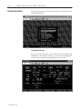
Using StrataSet Menus
All the choices needed to configure your reader are available through
pop-up windows that appear when ENTER is pressed at any of the
menu headings. At the Main Menu, highlight Configuration Screen
(or press 1)and press ENTER to view the Configuration Screen.
Use the following method to view a pop-up menu:
1. Use the TAB, up, down, left, or arrow keys to move the highlight
to the desired menu choice.
2. Once the menu choice is highlighted, press ENTER. A pop-up
menu then appears with various option choices.
Use the following method to select item(s) from within the pop-up
menu:
1. Use the PAGE UP, PAGE DOWN, up arrow or down arrow keys
to position the cursor on the desired option.
2. If the menu is a multiple choice menu, such as the Interface
menu, press ENTER to select the desired option. If the menu
contains brackets [ ], then you may either select or deselect the
particular option. Press the SPACE BAR to toggle the selection and
then hit ENTER when all selections are complete.
Publication 2755-6.14
Variable Content TTL:Chap Is Linked To HD:Running
Keyboard Commands
1–3
The following keys perform a given function as described below.
Function Key
Description
ENTER
To display a list of options for a given vertical field
within the Configuration Screen or to select a Main
Menu screen choice, position the cursor on the
desired field and press ENTER. ENTER will also
allow you exit from a pop-up window menu.
SPACE BAR
Within the pop-up window menus, an option may
have a left and right bracket before the menu
choice. These options can either be enabled or
disabled. To enable or disable an option, position
the cursor on the menu choice and press the
SPACE BAR key. When a check mark is within
the brackets, the option is enabled.
ESC Exit
Escape will also allow you to escape out of most
situations.
F1 Help
For a brief description of the function of a vertical
menu, position the cursor on the desired field and
press F1. To exit help, press ESC.
If you are within the Configuration Screen, hitting
F3 puts the reader into Program Mode.
F3 Enter Program Mode or Create
Choice File
If you are at the Main Menu screen, F3 allows you
to generate a text file, listing all options a particular
configuration file has enabled. For example, if you
want a listing of all the enabled settings your reader
has, refer to Program Mode, Getting Scanner
Settings and Saving Settings to File. Select the
filename from the file list, hit F3 and a file listing all
enabled choices within that file is created in your
working directory. This file will share the same
filename, except that it will have a .set extension.
F5 Program Scanner
After the desired parameters are selected in the
Configuration Screen, press F5 to program the
reader to those same settings. (This assumes you
have already entered Program Mode successfully.)
F7 Save Parameters
To save the various parameters selected in the
Configuration Screen, press F7. The settings are
then saved in a file for future reference and
programming. When assigning a filename, use the
proper DOS convention. StrataSet automatically
saves the file with the extension .TRK. The file is
saved to the same drive and directory from which
StrataSet is being run.
F9 Return to Main Menu or Delete
File
If you select File List from the Main Menu, you are
able to delete files by hitting F9. You will be
prompted to verify your selection (ESC terminates
the process). If you are within the Configuration
Screen, pressing F9 returns you to the Main Menu.
Publication 2755-6.14
1–4
Variable Content TTL:Chap Is Linked To HD:Running
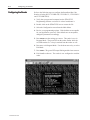
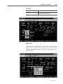
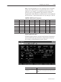
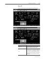
StrataSet Main Menu
The following sections describe the menu choices available from the
StrataSet Main Menu.
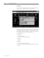
Configuration Screen
Press 1 to activate this option, or move the cursor to this location and
hit ENTER. By choosing this option, you will enter the Configuration
screen, where custom reader configurations can be created.
Publication 2755-6.14
Variable Content TTL:Chap Is Linked To HD:Running
1–5
This screen also allows you to save and/or download configurations
to the reader. The settings first displayed are the StrataSet RS232
default settings, not the reader settings. With the methods described
under “Using the StrataSet Menus” you are able to move around this
screen and change options. After configuring the screen for your
particular application, you can save the screen to a file, download the
settings to the reader, or both.
Get Scanner Settings
Press 2 to activate this option, or move the cursor to this location and
hit ENTER. This option lets you view the reader’s configuration by
uploading the information from the reader through your PC’s COM
port. You must first enter Program Mode to initialize
communications between the PC and the reader. (See Enter Program
Mode for more information). Once you have entered Program Mode
and selected this option, the configuration screen displays the
reader’s programmed parameters. The reader beeps once if it has
successfully entered Program Mode. The reader beeps again (either
3 times for the 2755-LHR-3C or 5 times for the 2755-LHR-5B, 5C
and 5BX1) when it has transmitted its configuration. You must exit
Program Mode after getting the reader’s configuration, before you
can resume normal scanning. (See Exit Program Mode for more
information).
File List
Press 3 to activate this option or move the cursor to this location and
hit ENTER. By choosing this option, a list of .TRK files residing in
the current directory is displayed. After highlighting a filename, you
can hit ENTER and the file is transferred to the Configuration screen.
You can delete the file by pressing F9, or hit F3 to generate a .SET
file listing all enabled reader options in that file.
Select Com Port
Press 4 to activate this option, or move the cursor to this location and
hit ENTER. This option allows you to select either Com1 or Com2.
You may be prompted to select a Com Port during various steps of
the programming or uploading sequence.
Enter Program Mode
Press 5 to activate this option, or move the cursor to this location and
hit ENTER. This function prepares the reader for communication
interfacing. One long beep from the reader indicates a successful
entry into program mode.
Publication 2755-6.14
1–6
Variable Content TTL:Chap Is Linked To HD:Running
Exit Program Mode
Press 6 to activate this option or move the cursor to this location and
hit ENTER. This option causes the reader to exit programming mode.
Three beeps from the reader indicates a successful exit from Program
Mode. Note that if you program the reader from the Configuration
screen, the program exits Program Mode if you press F5. Once you
exit Program Mode, you are then able to resume normal scanning.
Software Compatibility
Press 7 to activate this option, or move the cursor to this location and
hit ENTER. This option returns the firmware version installed in the
reader and specifies if it is compatible with existing StrataScan
software. Hitting any key returns you to the current screen. To
perform this test, it is not necessary to enter Program Mode first.
Exit to DOS
Press 8 to activate this option, or move the cursor to this location and
press ENTER. This option closes the program and returns you to the
DOS prompt or Windows.
Publication 2755-6.14
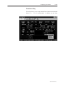
Configuring your Reader
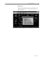
Introduction
By selecting “Configuration Screen” from the Main Menu, you are
able to access a menu screen from where you can setup custom
reader configurations, save configurations to a file, and program
your reader. This screen is divided into sections that let you
customize your reader configuration. To provide you with easier
programming, some of the parameters in the sections automatically
change when you choose from the different interface types (RS232
or Wand Emulation). It is recommended that you review all the
pop–down menu options, if interface types are changed.
To program your reader, you must first put the reader into Program
Mode, in order to establish communications between the reader and
your host. By pressing F3 while in the Config screen you will enter
the Program mode. Or you can enter the Program mode from the
Main Menu. Make sure the program is selecting the same Com Port
as the one to which you are connected. A successful entry into
Program Mode is indicated by:
a beep from the reader and
the green LED begins to flash.
Once you have entered Program Mode, press F5 to download the
current configuration screen contents to your reader. Again, you will
hear a series of beeps from the reader. Once the reader has
completed its processing of the downloaded configuration, you will
hear a 3–beep sequence. The green LED then stops flashing,
signaling that the reader is ready to scan.
To save a configuration to a file, hit F7. You are then prompted for a
filename. The filename automatically gets a .TRK extension.
Follow normal DOS conventions for naming files. If the file already
exists, you will be prompted as to whether you want to overwrite the
existing file or not. If you need a printout of all the enabled options
from a particular reader, get the reader’s settings and save the
configuration to a file. Go to the main screen File List, highlight the
appropriate filename, and hit F3. A text file is then created in your
working directory listing all the enabled choices in that
configuration. The file has the same filename as the one you
selected, except for a .set extension. Use a text editor to print the
configuration file.
Not all options listed within the Configuration Screen are currently
supported by the reader. If an option is not supported, this document
will specify what that option is.
Publication 2755-6.14
2–2
Configuring your Reader
Configuring the Reader
Refer to the following steps to configure the StrataScan Bar Code
Readers (Catalog Nos. 2755-LHR-5B, 2755-LHR-3C, 2755-LHR-5C
and 2755-LHR-5BX1).
1. Verify that your personal computer has the STRATCFG
Programming Software version 4.19 or later loaded onto it.
2. Double–click on the STRATCFG icon or execute the file.
3. Select the Configuration screen from the Main Menu.
4. Review your programming options. If the defaults are acceptable
for your application, press F3. If the defaults are not acceptable,
change the parameters accordingly.
5. Press ENTER once the settings are correct. The reader is now in
Program Mode. The green LED on the reader flashes while the
red LED remains lit. A beep is emitted from the reader as well.
6. Press F9 to exit Program Mode. Use the down arrow key to select
Exit Mode.
7. Press ENTER. The green LED stops flashing and the laser turns on.
8. Exit StrataSet software. The reader is now configured to read bar
codes.
Publication 2755-6.14
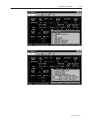
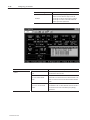
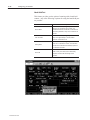
Configuring your Reader
Configuration Options
2–3
The following sections describe the various StrataScan Configuration
options available for the StrataScan Bar Code Readers.
Interface Format
This upper left–hand corner of the Configuration Screen gives you
the ability to specify the proper communications format, along with
all of an interface’s associated options. Specifying options is
accomplished for communicating to your host device. And when
you change between different interfaces, the Configuration screen
changes accordingly. It lets you change all options supported by that
interface and protects all those unsupported ones by means of cursor
skip–over. The StrataScan line of Readers supports RS232/RS422
and wand emulation. Choose an interface that matches your host
system requirements.
Select the RS232/RS422 option, if the reader is intended to be used
with either RS-232 ± 12V or RS422 serial output. StrataSet software
uses this interface to configure your reader.
Select Wand Emulation if the reader is used in place of a wand. It
provides Wand Emulation of each bar code scanned. Refer to the
section about Wand Type interface format for specific information
about Wand Emulation options.
The No Communication option is reserved for testing purposes. If
no communication is selected, then the center of the left–hand side of
your Configuration screen is empty.
Publication 2755-6.14
2–4
Configuring your Reader
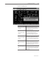
Code Types
This portion of the Configuration Screen lets you specify the various
bar code types to enable or disable for your application.
Within the Codes Menu Screen, you may enable or disable the codes
you want your reader to see or ignore. If a code is enabled, a check
mark appears between the two brackets. Then the reader recognizes
the enabled type of bar code. The types of codes are:
• All UPC/EAN
• Code 39
• Full ASCII Code 39
• Code 39 Mod 43 check digit required
• Code 93
• Code 128
• Codabar
• I2 of 5
• I2 of 5 Mod 10 check digit required
• EAN-8 disable, EAN-13 disable, UPC-E disable, UPC-A disable
• Paraf
Publication 2755-6.14
Configuring your Reader
2–5
Supplementals
This box in the Configuration screen gives you the ability to select
supplemental support options. Not all supplemental options are
currently supported.
Publication 2755-6.14
2–6
Configuring your Reader
Supplemental Type
Publication 2755-6.14
Description
2 Digit
When this option is enabled, the reader scans bar
codes that have 2-digit supplementals.
5 Digit
When this option is enabled, the reader scans bar
codes that have 5-digit supplementals.
977 (2–Digit)
When this option is enabled, the reader requires that
a 2-digit supplement be attached to an EAN-13 bar
code whenever the bar code begins with 977.
Bookland
When this option is enabled, the reader requires that
a 5-digit supplement be attached to an EAN-13 bar
code, whenever the bar code begins with 978.
Redundancy 2 Digits
When this option is enabled, the reader scans the bar
code plus the 2-digit add-on twice, before accepting
the data as valid information.
Redundancy 5 Digits
When this option is enabled, the reader scans the bar
code plus the 5-digit add-on twice, before accepting
the data as valid information.
Require Supps
When this option is enabled, all UPC/EAN labels that
are scanned must have a supplement.
100 ms to find Supps
When this option is enabled, the reader looks for a
supplement attached to a bar code, for a maximum of
100 msec.
200 ms to find Supps
When this option is enabled, the reader looks for a
supplement attached to a bar code, for a maximum of
200 msec.
Code 128 Coupon Option
When this option is enabled, the reader scans UPC-A,
followed by a Code 128 supplement attached.
Code 128 Coupon Conversion
When this option is enabled and when Code 128
coupon option is enabled, a ]C1 is transmitted
between the UPC-A bar code and Code 128
supplement.
378/379 lock on supplement
When this option is enabled, all EAN-13 labels are
expected to have a 5-digit supplement attached, when
the bar code begins with a 378 or 379.
Remote supplement required
When this option is enabled, the host can enable/
disable supplements required, with an ‘R’ (disable
requirement) and an ‘N’ (enable requirement).
Configuring your Reader
2–7
Miscellaneous
This section provides you with the ability to select various
miscellaneous functions including beep before/after transmit,
communication timeouts, multiple scan buffers, and others.
Publication 2755-6.14
2–8
Configuring your Reader
Miscellaneous Type
Beep after transmitting
Beep before transmitting
When this option is enabled, the reader beeps before
each bar code is transmitted.
Faster Beep/Same Tone
When this option is enabled, the beeper tone remains
the same, but the beep duration is approximately 1/2
normal duration.
Lost Communication Timeout
When this option is enabled, the reader automatically
times out after 2 seconds, if unable to complete its
data transmission to the host. This is only valid in
modes where some type of handshaking is involved.
3 beeps on timeout
When this option is enabled, the reader beeps 3 times
when communications have timed out. Lost
communication timeout must be enabled for this
option to be valid.
razz beep on timeout
When this option is enabled, the reader produces a
razzberry tone when communications have timed out.
Lost communication timeout must be enabled for this
option to be valid.
5 retrys before timeout
When this option is enabled, the reader attempts to
re-establish communications 5 times before timing
out. Lost communication timeout must be enabled for
this option to be valid.
Support ‘D/E’ disable/enable
commands
When this option is enabled, the reader suspends
scanning when it receives an ASCII ‘D’ from the host
device. All timing functions continue. If the reader
receives an ASCII ‘d’, scanning is again suspended,
plus all buffers are cleared as well. Scanning
resumes when the reader receives an ASCII ‘E’ or
‘e’. This feature only works with RS-232
communication.
Support ‘F/L’ Laser off/on
commands
When this option is enabled, an ASCII ‘F’ turns off the
lasers and ASCII ‘L’ turns on the lasers.
Disable segmented decoding
This option disables UPC Split Code Algorithm. This
feature allows for increased scanning accuracy in
reading poor quality bar codes, but may slightly
reduce the aggressiveness of the reader.
Table continued on the next page.
Publication 2755-6.14
Description
When this option is enabled, the reader beeps after
each bar code is transmitted. If ACK/NAK is enabled,
the reader always beeps after receiving the ACK
command.
Configuring your Reader
Miscellaneous Type
2–9
Description
1, 2, 4 and 8 Compare Buffers
The option selected here determines how many bar
codes are buffered in reference to same symbol
comparisons. This value should always be equal to or
greater than the number of different bar codes you
expect to scan on each package to avoid the potential
of double reads.
Scan Count
When this option is enabled, the reader enters scan
count test mode. Do not enable this feature unless
instructed to do so by a Rockwell Automation
representative.
Reverse LED convention
Normal LED convention calls for the red LED to
signify power/ready to scan and the green LED for
transmit indicator. When this option is enabled, the
functions of the two LED’s are switched.
Support multiple beep ‘B’/
razz ‘Z’ commands
When this option is enabled, the reader recognizes a
multiple beep/razz command from the host. The
command is a number, from 1 to 9, followed by an
ASCII ‘B’ or an ASCII ‘Z’.
Support host BEL/CANCEL
commands
When this option is enabled, the reader beeps when it
receives a BEL (07H) command from the host. If
ACK/NAK is enabled, a BEL command causes the
reader to beep 3 times, if sent first after a bar code is
transmitted. Or it will cause the reader to beep once if
ACK/NAK is not enabled. If a CAN (18H) command is
sent from the host, the reader exits out of its
communication loop without a beep and clears all
buffers.
Enter program mode only after
power-up
Normally, you may enter Program Mode at any time.
When this option is enabled, you are restricted to
entering Program Mode, between initial power–up and
before your first scan only. If you select this option
and need to modify the reader parameters after
several scans, merely power–down and power–up the
reader again. Then enter into Program Mode before
scanning again.
Enable status reporting
When this option is enabled, the host can initiate a
status report download from the reader with a CTRL P
command (10H). Status information includes motor
status, laser status, decode board status, scan counts
per field since last power-up, slave status and
non-volatile memory status.
Number of good scans required
(1–8)
This number, from 1 to 8, is a redundancy counter
which refers to the number of times the reader must
scan a bar code, before it considers it a good scan
and transmits the bar code. The default of 1 is usually
fine for most symbologies. Values greater than 1 may
be needed when data integrity is most critical. Note
that as the number of good scans required is
increased, aggressiveness will decrease.
Table continued on the next page.
Publication 2755-6.14
2–10
Configuring your Reader
Miscellaneous Type
Publication 2755-6.14
Description
Special code select
When this option is enabled and the Enter key is hit
on this choice, a custom reader parameters window
appears. This window allows you to select up to 5
code and length–specific code selects. The reader
only scans those codes at the programmed lengths
entered here. When used in conjunction with
Package Detect and multiple scans per activation, the
reader scans and buffers the programmed bar codes.
It transmits them in the order that they were
programmed within the window. See Package Detect
and Multiple Scans per activation for more details.
Use the arrow keys to move around the screen. Use
the Enter key to save the current code select choice
and advance to the next choice. Use the backspace
key to go back to the previous choice. Hit F10 to
save these settings and return to the configuration
screen or hit Escape to exit without saving changes.
Normal/Loud Volume
Select the desired loudness with these 2 options.
Support ‘M/O’ motor on/off
commands
When this option is enabled, the reader accepts ‘M’
motor on and ‘O’ motor off commands from the host.
The motor off command causes the lasers to go off,
the motor to shut down, and the power LED to go off.
A motor on condition turns the motor back on and the
power LED to come on. The lasers do not turn on
until the motor comes up to full speed (approx. 45-50
seconds).
Support non–decode hand–held
port
This option enables the reader to support an
undecoded hand–held reader connnected the
hand–held port. When this option is enabled, the HH
(Hand– Held reader option) window at the bottom of
the configuration screen displays all currently
supported Hand–Held options.
Configuring your Reader
2–11
Package Detect
This section provides you with all the choices currently supported for
Package Detect options. Special software is not required to support
the following options. The appropriate hardware comes standard
internal to the 2755-LHB-1 Interface Box and reader. The hardware
interfaces with up to 2 Package Detect inputs and an Output/Alarm
Output.
Publication 2755-6.14
2–12
Configuring your Reader
Output/Package Detect Type
Support package detect
Support package detect alarm
input
When this option is enabled, the reader produces a
steady stream of beeps, if the sensor alarm is
activated.
Transmit ‘No Read’ message on
package detect timeout
When this option is enabled, the reader transmits ‘NO
READ’ if a no read condition occurs. If a custom
message is desired, refer to programmable no read
message (see below). This function also supports the
following prefixes and suffixes: TAB prefix, CR, LF,
ETX, STX, programmable prefixes and suffixes, and
TAB suffix.
Scans per package detect
activation (1-5)
This option allows you to determine how many
different bar codes the reader expects to see per
sensor activation. To avoid multiple reads of the same
bar code, make sure the same symbol timeout is set
accordingly and the number of scan buffers is equal to
or greater than this number.
Scanner activation time after
package detection (sec)
Support Package Detect must be enabled first before
a value can be entered here. The value here
determines how long the reader will look for a bar
code before timing out. If the value is less than 9
seconds (minimum of .1 seconds), the reader will be
active for this amount of time. If the value is greater
than 9 seconds, the reader remains active as long as
the Package Detect is active. If dual line sensor is
enabled, this value is forced to 9.9 seconds.
Support AC output
When this option is enabled, the reader will activate
the output according to the selections below.
Table continued on the next page.
Publication 2755-6.14
Description
When this option is enabled, scanning is disabled until
a Package Detect activation is detected. In the first
mode, if the scan duration (see below) is set for less
than 9 seconds, the reader is active for scanning for
the programmed scan duration. In the second mode,
if scan duration is set for greater than 9 seconds, the
reader is active for scanning as long as the sensor
remains active. After a scan cycle completes, the
sensor must turn off momentarily before the next valid
activation is recognized. In the third mode, dual line
sensor support, this value is automatically set to 9.9
seconds.
Configuring your Reader
Output/Package Detect Type
2–13
Description
AC output Controlled by Host
(DC2/DC4)
When this option is enabled, the host assumes full
control for activating and deactivating the Output. To
turn the Output on, the host must send a CTRL R
(12H) character. To turn the Output off, the host must
send a CTRL T (14H) character. The support Output
option must be enabled first in order to select this
option.
AC output Normally On
The default mode of the reader is to have the Output
normally off. When this option is enabled, the Output
is normally on.
Enable Read and Match mode
This option is an Output function. Support Output
must be enabled before this option is valid. When this
option is enabled, the reader stores in memory the
next bar code it reads after either powering–up or
after being programmed via StrataSet. The reader
emits a unique beep sequence as an indicator that it’s
taking the bar code as a read and match bar code.
From that point on, the Output operates according to
whether output on good read/match is enabled or
output on bad match is enabled. Normally, if this
option is enabled, a new read and match bar code is
stored after each power-up and after each StrataSet
programming session. If desired, you may enable
save read and match bar code (see below) to
preserve the read and match bar code, if power is
lost.
Activate AC output if good
read/match
This option is an Output function. Support Output
must be enabled before this option is valid. When this
option is enabled, if read and match is enabled (see
above), this feature reads “Output on a good match”.
The Output will turn on every time a scanned bar code
matches the read and match bar code. If read and
match is not enabled, the feature reads “fire Output on
good read”. The Output turns on every time the
reader scans a good read.
Activate AC output if bad match
This option is a read and match function as well as an
Output function. Both options must be enabled before
this option is valid. When this option is enabled, the
Output turns on every time a scanned bar code does
not match the read and match bar code. See Enable
read and match option above for details on setting up
for read and match mode.
Activate AC output if no read
This option is a Package Detect function as well as an
Output function. Both options must be enabled before
this option is valid. When this option is enabled, the
Output will turn on if a no read condition occurs. A no
read condition occurs if the reader reaches a sensor
timeout before a bar code is scanned (see support
Package Detect) It also occurs if the line sensor turns
off before a bar code is read (if scan duration is
greater than 9 seconds).
Table continued on the next page.
Publication 2755-6.14
2–14
Configuring your Reader
Output/Package Detect Type
AC output Duration (sec)
Delay Time before activating AC
output (sec)
The value entered here determines how long the
reader delays after its normal activation time before
acivating the output. The default value of 0.0 should
be sufficient for almost all applications. Use this
option only if it is impossible to mount the reader at
the Output location.
Enable programmable ‘No Read’
message
When this option is enabled, you will be able to
program your own no read message. The message
can be up to 10 characters long and can include any
of the human readable ASCII set (20h to 7fh). Note
that the message is right–justified when transmitted
from the reader. If this option is being used with
Wand Emulation output, the reader defaults to output
as Code 39 so the message must be within the
normal Code 39 range of characters.
Retain same symbol timers after
package detect cycle ends
Under normal Package Detect support conditions, the
reader resets scan buffers after a complete sensor
cycle. Same symbol timers prevent multiple reads
during the scan cycle. But as soon as the cycle
completes and the next Package Detect is
recognized, all buffers are cleared and the reader
scans any bar codes in the field. When retain same
symbol buffers with Package Detect is enabled, same
symbol timers do not automatically reset after a
completed sensor cycle. Rather, they reset after the
same symbol timer times out. This feature can be
useful under these 3 conditions: packages are spaced
relatively closely, the bar codes on consecutive
packages are the same and the possibility of a
package triggering a Package Detect while the box is
still in the scan field exists.
Save read and match bar code if
power–down
Under normal operations, when read and match mode
is used, a new read and match bar code is stored
immediately after the reader has been powered–up or
after the reader has been programmed through
StrataSet. When save read and match bar code on
power–down is enabled, the read and match bar code
is saved during a power-down, and a new read and
match is only accepted after programming the reader.
Support dual package detect
inputs
When this option is enabled, the reader uses the
current line sensor ALARM input as the second
Package Detect input. The current line sensor input
acts as the start of activation cycle, and the second
Package Detect input acts as the end of activation
cycle.
Table continued on the next page.
Publication 2755-6.14
Description
The value entered here determines how long the
Output/alarm output remains active.
Configuring your Reader
Output/Package Detect Type
2–15
Description
Buffer scans until package
detect cycle completes
StrataScan Readers have the ability to buffer all bar
codes as they are scanned (with Package Detect
support enabled). If this option is enabled, all
scanned bar codes are buffered during the active
sensor cycle and are not transmitted, until the
activation cycle has completed. This feature is
supported with all 3 Package Detect mode options. If
this feature is not enabled, all scanned bar codes are
transmitted as they are scanned. This option does not
apply to the special code select feature, which always
buffers incoming bar codes.
Enable host package detect
emulation
When this option is enabled, the host simulates the
Package Detect input(s) by sending an ‘S’ (53h)
character and an ‘X’ (58h) character. If dual Package
Detects is enabled, the ‘S’ simulates the Package
Detect input 1 and the the ‘X’ simulates the Package
Detect input 2. If a finite scan duration is being used,
the ‘S’ character starts the cycle. If scan duration > 9
seconds (reader active until the sensor goes away),
the ‘S’ starts the cycle and the ‘X’ ends the cycle.
Scan Range
This section provides depth of field options. Long depth of field
should be enabled in all StrataScan Readers. The 2 reserved options
are not currently supported and are reserved for future use.
Publication 2755-6.14
2–16
Configuring your Reader
Reserve Codes
This section provides 98 reserved functions available to enable future
special software features. Do not enable any reserve codes unless
told to do so by a company representative.
RS232 Format
This section provides you with all the interface format–specific
options. If RS232 is selected in the Interface Format menu, these
menus are displayed as RS232 specific menus.
Publication 2755-6.14
Configuring your Reader
2–17
Baud Rate
Rate
Baud Rate
Description
Data is transferred at either 300, 600, 1200, 2400,
4800, 9600, 19200, or 38400 baud.
Data Format
These choices represent the parity of the data byte. Parity is an extra
bit attached to the transmitted data byte and is used to catch potential
single-bit data transmission errors. The reader’s parity must match
the host’s parity.
Publication 2755-6.14
2–18
Configuring your Reader
RS232 Type
Data Format
Description
Odd
Select odd to make the parity bit either a 0 or 1, to guarantee
an odd number of ones.
Space
Select space to make the parity bit always 0.
Even
Select even to make the parity bit either a 0 or 1, to guarantee
an even number of ones.
Mark
Select mark to make the parity bit always 1.
None
Select none and the parity bit time is skipped.
7 or 8 Data Bits
Select between 7 and 8 data bits per data byte, depending on
the requirements of your host.
1 or 2 Stop Bits
Select between 1 and 2 stop bits per data byte, depending on
the requirements of your host.
Note: The StrataScan line of Readers supports either 10 or 11 bit
data words. You cannot choose a data byte format that is not either
10 or 11 data bits total (including 1 start bit). For example, you
cannot select 7 data bits, 1 stop bit and no parity, since this would
constitute a 9-bit data byte. You cannot choose 8 data bits, 2 stop
bits and a parity bit, since this would constitute a 12-bit data byte,
including 1 start bit.
Further RS232 Options
RS232 Type
Options
Publication 2755-6.14
Description
Reserved 1
This option is reserved for future use.
Reserved 2
This option is reserved for future use.
ACK/NAK
After a bar code is scanned and transmitted, if ACK/NAK is
enabled, the reader waits for one of several host character
commands to be sent from the host. If the host sends an ACK
(06H) acknowledge command, the reader beeps and resumes
scanning. If the reader receives a NAK (15H) negative
acknowledge command, the reader re-transmits the bar code
without a beep and does not resume scanning.
CR
When this option is enabled, the reader transmits a Carriage
Return after each bar code.
LF
When this option is enabled, the reader transmits a Line Feed
after each bar code.
DTR Support
When this option is enabled, the reader requires a Data
Terminal Ready (DTR) signal to be present before scanning.
Configuring your Reader
2–19
Publication 2755-6.14
2–20
Configuring your Reader
RS232 Type
Options
Description
When this option is enabled, the reader transmits Nixdorf code
identifiers before each bar code as follows:
Nixdorf ID
Code
Prefix Code
UPC-E
d
UPC-A
c
EAN-8
g
EAN-13
h
Code 39
b
Codabar
a
Code 93
i
I 2 of 5
e
Code 128
j
RTS/CTS handshaking
When this option is enabled, the reader outputs a Request To
Send (RTS) signal and waits for a Clear To Send (CTS) signal
before any data is transmitted.
RTS/CTS (character)
When this option is enabled, the reader activates and
deactivates its RTS signal after each character it transmits.
RTS/CTS (message)
When this option is enabled, the reader activates and
deactivates its RTS signal after each message it transmits.
ETX suffix
When this option is enabled, the reader transmits an End of
Text after each bar code.
STX prefix
When this option is enabled, the reader transmits a Start of
Text before each bar code.
Tab prefix
When this option is enabled, the reader transmits a TAB
before each bar code.
Tab suffix
When this option is enabled, the reader transmits a TAB after
each bar code.
UPC prefix
When this option is enabled, the reader transmits a prefix
before any UPC/EAN bar codes. The prefixes are A (UPC A),
E0 (UPC E), F (EAN 13), and FF (EAN 8).
UPC suffix
When this option is enabled, the reader transmits a suffix after
any UPC/EAN bar codes. The suffixes are A (UPC A), E0
(UPC E), F (EAN 13), and FF (EAN 8).
Schlumberger/Shell format
When this option is enabled, the reader transmits an XOR’ed
check digit of all the data characters at the end of the data
stream.
Table continued on the next page.
Publication 2755-6.14
Configuring your Reader
RS232 Type
Options
2–21
Description
Transmit AIM ID Character
When this option is enabled, the reader transmits special AIM
code identifiers before each bar code as follows:
Code
AIM Code ID
UPC-E
]Z0
UPC-E with 2–digit suppl.
]Z0
UPC-E with 5–digit suppl.
]Z0
UPC-A
]Z0
UPC-A with 2–digit suppl.
]Z0
UPC-A with 5–digit suppl.
]Z0
EAN-8
]E4
EAN-8 with 2–digit suppl.
]E4
EAN-8 with 5–digit suppl.
]E4
EAN-13
]E0
EAN-13 with 2–digit suppl.
]E0
EAN-13 with 5–digit suppl.
]E0
Code 39
]A0
Code 39 FA
]A4
Code 39 with MOD 43
]A3
Code 39 with MOD 43 plus
transmit CD
]A1
Code 39 Full ASCII with
MOD 43
]A7
Code 39 Full ASCII with
MOD 43 plus transmit CD
]A5
Codabar
]F0
Codabar with start and stop
characters
]F1
Code 93
]G0
I 2 of 5
]I0
I 2 of 5 with MOD 10
]I2
I 2 of 5 with MOD 10 and
transmit MOD 10
]I1
Code 128
]C0
Table continued on the next page.
Publication 2755-6.14
2–22
Configuring your Reader
RS232 Type
Options
Publication 2755-6.14
Transmit Sanyo ID Character
Description
When this option is enabled, the reader transmits special code
identifiers before each bar code as follows:
Code
Prefix Code
UPC-A
C
EAN-8
A0
EAN-13
B
Code 39
A
Codabar
M plus 2–digit hexadecimal
representation of the
character count
Code 93
L plus 2–digit hexadecimal
representation of the
character count
I 2 of 5
I plus 2–digit hexadecimal
representation of the
character count
Code 128
K plus 2–digit hexadecimal
representation of the
character count
SNI Beetle Mode
This feature is not currently supported.
French PC Terminal Emulation
This feature is not currently supported.
Xon/Off handshaking
When this option is enabled, the reader does not transmit after
an XOFF is received. Transmission resumes after an XON is
received.
Programmable prefix identifiers
When this option is enabled, one or two programmable prefix
ID characters can be assigned and added to the scanned data
transmission. To assign the character, refer to the options
Xmit (Transmit) as 1st prefix identifier or Xmit as 2nd prefix
identifier below.
Transmit as 1st or 2nd prefix
identifier
When the Programmable prefix identifiers option is enabled, a
programmable prefix ID character can be entered in either of
these 2 windows. (The decimal equivalent of the ASCII value
of the key pressed is then displayed).
Programmable suffix identifiers
When this option is enabled, one or two programmable suffix
ID characters can be assigned and added to the scanned data
transmission. To assign the character, refer to the options
Xmit (Transmit) as 1st suffix identifier or Xmit as 2nd suffix
identifier.
Transmit as 1st or 2nd suffix
identifier
When the Programmable suffix identifiers option is enabled, a
programmable suffix ID character can be entered in either of
these 2 windows. (The decimal equivalent of the ASCII value
of the key pressed is then displayed).
Configuring your Reader
2–23
Note: The following table of 32 ALT characters can be used along
with the above RS232 options as programmable prefix or suffix
identifiers. For example, if you wanted to use the carriage return
character (CR) as a programmable suffix identifier, select the
Programmable suffix identifier as an RS232 choice in the OPTIONS
pull–down menu. Then hold down the ALT key and type CTRL M.
CONTROL CODES for ALT characters
Character
Control Code
Character
Control Code
Character
Control Code
Character
Control Code
NULL
CTRL 2
BS
CTRL H
DLE
CTRL P
CAN
CTRL X
SOH
CTRL A
HT
CTRL I
DC1
CTRL Q
EM
CTRL Y
STX
CTRL B
LF
CTRL J
DC2
CTRL R
SUB
CTRL Z
ETX
CTRL C
VT
CTRL K
DC3
CTRL S
ESC
CTRL [
EOT
CTRL D
FF
CTRL L
DC4
CTRL T
FS
CTRL \
ENQ
CTRL E
CR
CTRL M
NAK
CTRL U
GS
CTRL ]
ACK
CTRL F
SO
CTRL N
SYN
CTRL V
RS
CTRL 6
BEL
CTRL G
SI
CTRL O
ETB
CTRL W
US
CTRL _
Wand Emulation Format
If Wand Emulation format is selected in the Interface Format menu
instead of RS232/422, then Poll Source, High Output and Options
boxes display as Wand Emulation specific options.
Wand Type
Poll Source
Description
When poll source is enabled, the reader does not
scan unless a 5–volt signal is seen on the poll source
input.
Publication 2755-6.14
2–24
Configuring your Reader
Wand Type
Hi/Output
Wand Type
Options
Publication 2755-6.14
Description
Under this menu, you may program the reader to
transmit as one of either Bars high as Code 39.
Spaces high as Code 39. Bars high as scanned or
Spaces high as scanned. Select the method that
matches your host’s requirements.
Description
Extra Transition before Bar
Code
If your host requires it, the reader can output an extra
transition before each bar code.
50x or 10x narrow element
border
This option selects whether the borders on the transmitted bar
code will be 10 or 50 times the size of a narrow element. This
value is a function of the size of the narrow element selected
below.
1.0, 0.5, 0.3, 0.15 ms narrow
element
This option selects the size of the narrow element of the
transmitted bar code. All other elements in the bar code are a
direct function of this value as dictated by the symbology
specification.
Configuring your Reader
2–25
Formatting
This section gives you several output format options for UPC/EAN
and non-UPC bar codes. These menus are not supported if using
Wand Emulation.
UPC Formatting Types
Publication 2755-6.14
2–26
Configuring your Reader
Formatting Type
Publication 2755-6.14
Description
Convert EAN-8 to EAN-13
When this option is enabled, the reader converts
EAN-8 to EAN-13 by transmitting five zeroes before
the bar code.
Convert UPC-A to EAN-13
When this option is enabled, the reader converts
UPC-A to EAN-13 by transmitting a leading zero
before the bar code.
Expand UPC-E
When this option is enabled, the reader expands
UPC-E to the 12–digit equivalent UPC-A.
Transmit lead zero on UPC-E
When this option is enabled, the reader outputs a zero
before each UPC-E bar code.
Transmit UPC-A check digit
When this option is enabled, the reader transmits the
UPC-A check digit.
Transmit UPC-A Number
System
When this option is enabled, the reader transmits the
UPC-A number system character. Duplicate numbers
may result at the host end, when the reader is
programmed not to transmit the UPC-A number
system character.
Transmit UPC-E check digit
When this option is enabled, the reader transmits the
UPC-E check digit.
Transmit EAN–13 check digit
When this option is enabled, the reader transmits the
EAN–13 check digit.
Transmit EAN–8 check digit
When this option is enabled, the reader transmits the
EAN–8 check digit.
Configuring your Reader
2–27
Non-UPC Formatting Types
Non-UPC Formatting Type
Description
CLSI Editing
When this option is enabled, the reader performs
CLSI library type editing before the information is
transmitted to the host. This editing only works with
14–digit Codabar type labels.
Transmit Codabar Start/Stop
Characters
When this option is enabled, the reader transmits
Codabar’s start and stop characters before and after
each bar code. This menu choice works in
conjunction with the Codabar option in the Codes
section. Both must be enabled for this feature to
work.
Transmit Code 39 Start/Stop
Characters
When this option is enabled, the reader transmits
Code 39’s start and stop character. This menu choice
works in conjunction with the Code 39 option in the
Codes section. Both must be enabled for this feature
to work.
Transmit I2 of 5 Mod 10 check
digit
When this option is enabled, the reader transmits the
Interleaved 2 of 5 (I2OF5) Mod 10 check character.
This menu choice works in conjunction with the I2OF5
Mod 10 option in the Codes section. Both must be
enabled for this feature to work.
Transmit Code 39 Mod 43 check
digit
When this option is enabled, the reader transmits
Code 39’s Mod 43 check character. This menu choice
works in conjunction with the Code 39 Mod 43 option
in the Codes section. Both must be enabled for this
feature to work.
Publication 2755-6.14
2–28
Configuring your Reader
Length Specifiers
This section provides you the option of restricting the size of the bar
codes that the reader accepts. The following are the options
available from the Length Specifiers section. From the following
menus, you can program the reader to scan only bar codes that meet
your defined criteria.
Note: The length specifier options are available from the main
configuration screen. As a result no pop–up menus are displayed
here.
Length Specifiers Type
Publication 2755-6.14
Description
I2 of 5 Locks (14 & 0)
The number of digits in the I2 OF 5 (Interleaved 2 of
5) bar codes that you are scanning are specified in
this field. Two individual values, ranging from 1-50
can be selected via the two fields below the I2 OF 5
option. The first field can be set to zero if you wish to
have the length variable. If you are only scanning one
length of I2 OF 5 bar codes, enter that value into the
first field and enter 0 in the second field. This causes
a lock on the first value. If you are scanning I2 OF 5
bar codes, it is strongly recommended that you
specify bar code lengths when possible, to help avoid
misreads.
Others (Min 4)
The minimum number of characters in the bar codes
that are scanned can be specified in this field. If, for
example, Min is set to 4, the reader does not scan bar
codes that have less than 4 characters. To change
this option, position the cursor on the field, type in the
new number, and press ENTER.
Others (Lock 0)
If the reader is always scanning bar codes of the
same length, the length of accepted bar codes can be
programmed into the reader with the Lock feature.
For example, if all the bar codes to be scanned are
seven–digit Code 39, a 7 can be entered in the Lock
field. If all bar codes being scanned are variable
lengths, type a zero in this field. If the Lock feature is
used, be sure that Mn is not greater than the Lock
value.
Configuring your Reader
2–29
Beeper/LED
This section provides for all the supported beeper/LED options.
Beeper/LED Type
Description
Beeper Tone
The following beeper tone options are available:
Normal, Alt 1, Alt 2, Alt 3, Alt 4, and no tone.
LED
Under normal conditions, the LED flashes upon good
scan and transmit. You can disable the LED flash, if it
is not necessary in your application (e.g., If the reader
is to be used in an unmanned application, where the
LED and beeper are not necessary). You may disable
both functions and save the reader time in beeping
and flashing.
Publication 2755-6.14
2–30
Configuring your Reader
Same Symbol Timeout
Same symbol timeout lists the amount of time to wait before a
communication error is detected and a message retry occurs.
Available choices are none, 100, 200 and 500 milliseconds, 1.25,
2.00 seconds and an infinite amount of time.
Publication 2755-6.14
Configuring your Reader
2–31
Transmission Delay
This option allows you to create standard inter–character transmission
delays of 1, 5 or 20 milliseconds, in addition to no delay.
Publication 2755-6.14
2–32
Configuring your Reader
Hand–Held Port
This feature provides you the option of scanning with a hand–held
scanner. Any of the following 4 options for using the hand–held port
are possible:
Hand–held Port
Publication 2755-6.14
Description
Normal Mode
The laser comes on upon triggering or IR detect and
will stay on for a minimum of 2.5 seconds, if no
black/white transitions are detected. If transitions are
continuously detected, it stays on for a maximum of 5
seconds.
One–shot mode
The laser comes on upon triggering or IR detect and
stays on for approximately 1 second, whether
transitions are detected or not.
Pulsing mode
The laser comes on upon triggering or IR detect and
pulses on for a minimum of 3 times, if no transitions
are detected. If transitions are detected, it pulses on
for a maximum of 6 times.
Test mode
In this mode, the laser remains on at all times. This
mode is strictly a test mode, and for laser safety
purposes, should not be used during normal
operation.
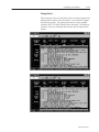
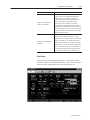
2–1
* - #,. ,- *).,*' * - !*, / ,. + , *+.$*)- #+. , *% .$0 - $.$)" *, * .1+ - *, * * * * # & $"$. * $-' $-' !/'' * *! *! * # & $"$. ,! $-' $-' * - , - ,0 +*,. *(()- & 1*, *)!$"/,.$*) *+.$*)- *)!$"/,.$*) -, ) *)!$"/,$)" 1*/, , , *)..$)" '' ),' 1 !*, --$-.) *). ).- *! .#$- )/' *).,*' * - !*, #,. ,- . !*,(. 0 ) (,& * -+ Publication 2755-6.14
2–2
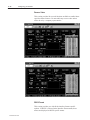
./+, &/. !"(4 /-*.)&..&+* "3&/ /+ E
'"4 '"4 "3&/ /+ F
'"4 '"4 '"4 '"4 '"4 '"4 #&(" (&./ #&-)2-" 1"-.&+* #+-)/
!/ &*/"-# " %(0)"-$"-%"(( 2*! ")0(/&+* #+-)//&*$
*+* #0-/%"- +,/&+*.
%*!.%'&*$ H
%*!%"(! ,+-/ &0/,0/ I
&!"*/&#&"-.
&3!+-# ,-+$-))(" ,-"#&3 ,-+$-))(" .0##&3 */"*!"! 0!&"* " &*/"-# " #+-)/ Publication 2755-6.14
2–3
K
" )' ( "-&( &$$%) L
&'*!&%) #%* )'!!() & #&") &* () M
$!% $%+ $%+# &%*%*) $%+# &%,%*!&%) $%+) &( *(** $!)##%&+)
' !)#) %#) (,() &%,%*!&% *!$&+* $!)##%&+) &'*!&%) $&
%&($# &%) &* '+#)!% N
%&% &($**!% O
&'*!&%)
'( +(* ( Publication 2755-6.14
2–4
$)(%)(
(*( ')%%$&( P
% (( #! & # "( $!! '$)& %$&( #! &$&" "$
#(& ,( R
&( ) !( )!($#' &'&* $' S
'" '-"$! ("$)( '# &# '##& '((#' '!( %$&( '$(+& *&'$# '% & '%&' !#( '(&(# (&(( ')%%!"#(!' ( ( $$ !# $ $#*&'$# "!!'$#' ($ # &)##- T
#! )%%$&( ('(# $%($# ("$)( '" '-"$! (&#'"''$# !- Publication 2755-6.14
2–5
#!"#
!#! ' !#! !## % $# % #' ! #" !!% # &#! #!"# ! ! $# $# !!% # "( "$! Publication 2755-6.14
Rockwell Automation helps its customers receive a superior return on their investment by bringing
together leading brands in industrial automation, creating a broad spectrum of easy-to-integrate
products. These are supported by local technical resources available worldwide, a global network
of system solutions providers, and the advanced technology resources of Rockwell.
Worldwide representation.
Argentina • Australia • Austria • Bahrain • Belgium • Bolivia • Brazil • Bulgaria • Canada • Chile • China, People’s Republic of • Colombia • Costa Rica • Croatia • Cyprus
Czech Republic • Denmark • Dominican Republic • Ecuador • Egypt • El Salvador • Finland • France • Germany • Ghana • Greece • Guatemala • Honduras • Hong Kong
Hungary • Iceland • India • Indonesia • Iran • Ireland • Israel • Italy • Jamaica • Japan • Jordan • Korea • Kuwait • Lebanon • Macau • Malaysia • Malta • Mexico • Morocco
The Netherlands • New Zealand • Nigeria • Norway • Oman • Pakistan • Panama • Peru • Philippines • Poland • Portugal • Puerto Rico • Qatar • Romania • Russia • Saudi
Arabia • Singapore • Slovakia • Slovenia • South Africa, Republic of • Spain • Sweden • Switzerland • Taiwan • Thailand • Trinidad • Tunisia • Turkey • United Arab Emirates
United Kingdom • United States • Uruguay • Venezuela
Rockwell Automation Headquarters, 1201 South Second Street, Milwaukee, WI 53204-2496 USA, Tel: (1) 414 382-2000 Fax: (1) 414 382-4444
Rockwell Automation European Headquarters, Avenue Hermann Debroux, 46, 1160 Brussels, Belgium, Tel: (32) 2 663 06 00, Fax: (32) 2 663 06 40
Rockwell Automation Asia Pacific Headquarters, 27/F Citicorp Centre, 18 Whitfield Road, Causeway Bay, Hong Kong, Tel: (852) 2887 4788, Fax: (852) 2508 1846
World Wide Web: http://www.ab.com
Publication 2755-6.14
PN 40062-390-01 (A)
Copyright 1997 Rockwell International Corporation. All rights reserved. Printed in USA
Publication 2755-6.14