1
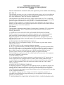
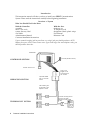
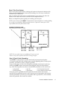
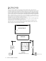
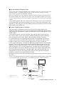
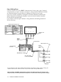
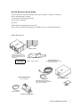
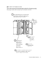
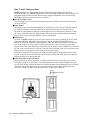
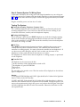
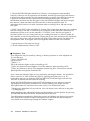
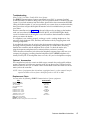
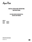
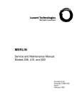
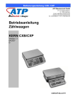
Lucent Technologies
Bell Labs Innovations
SPIRIT®
Communications System
Model 308/616
Customer Installation Instructions
999-500-226
105772578
Issue 4
June 1989
Intellectual property related to this product and registered to AT&T Corporation has been
transferred to Lucent Technologies Incorporated.
Any references within this text to American Telephone and Telegraph Corporation or AT&T
should be interpreted as references to Lucent Technologies Incorporated. The exception is
cross references to books published prior to December 31, 1996, which retain their original
AT&T titles.
Lucent Technologies – formed as a result of AT&T’s planned restructuring – designs,
builds, and delivers a wide range of public and private networks, communication systems
and software, consumer and business telephone systems, and microelectronic components.
The world-renowned Bell Laboratories is the research and development arm for the
company.
INTERFERENCE INFORMATION
FCC REGULATIONS PERTAINING TO THIS EQUIPMENT
NOTICE
Federal Communications Commission (FCC) rules require that you be notified of the following:
FCC (Part 15)
This equipment generates, uses, and can radiate radio frequency energy and, if not installed and
used in accordance with the instructions in the installation, administration and user manuals
may cause interference to radio and television communications.
This equipment has been tested and found to comply with the limits for a Class A computing
device, pursuant to Subpart J of Part 15 of FCC Rules, which are designed to provide reasonable
protection against such interference when operated in a commercial environment.
Operation of this equipment in a residential area may cause interference with nearby radios or
television, in which case the owners (at their expense) will be required to take whatever measures
may be necessary to correct the interference.
FCC (Part 68)
This equipment is registered with the Federal Communications Commission (FCC) in accordance
with Part 68 of its Rules. The FCC requires that the manufacturer provides you with the
following information:
1. CONNECTION AND USE WITH THE NATIONWIDE TELEPHONE NETWORK
The FCC requires that you connect your telephone equipment to the nationwide telephone
network through a standard telephone network interface jack such as a USOC RJ11C.
Registered equipment may not be used with Coin Telephone Lines. Equipment may be used
with Party Lines in areas where state tariffs permit such connections and when equipment is
adaptable for such use.
2. INFORMATION FOR THE TELEPHONE COMPANY
Upon request of your local telephone company, you are required to provide them with the
following information:
A. The lines to which you will connect the telephone equipment.
B. The FCC registration number, AS593M-72132-KF-E, and ringer equivalence number (REN),
0.3A/0.5B. Both numbers are on the controller. The REN is useful to determine how many
devices you may connect to your telephone line and still have them ring when your telephone
line is called. In most, but not all areas, the sum of all REN’s per line should be 5 or less.
You may want to contact your local telephone company for specific information.
The local telephone company must also be notified upon final disconnection of the equipment
from the local telephone company lines.
3. REPAIR INSTRUCTIONS
If it is determined that your telephone equipment is malfunctioning, the FCC requires that it
not be used and that it be unplugged from the modular outlet until the problem has been
corrected. Repairs to this equipment can be made only by the manufacturer or its authorized
agents. For repair procedures, follow the instructions outlined under the AT&T Limited
End User Warranty.
4. RIGHTS OF THE TELEPHONE COMPANY
If telephone equipment is causing harm to the telephone network, the telephone company may
temporarily discontinue your telephone service. If possible, they will notify you before they
interrupt service. If advance notice is not practical, you will be notified as soon as possible.
You will be given the opportunity to correct the problem, and you will be informed of your right
to file a complaint with the FCC.
Your telephone company may make changes in its facilities, equipment, operations, or
procedures that could affect the proper functioning of your equipment. If such changes are
planned, you will be notified.
5. THIS EQUIPMENT IS COMPATIBLE WITH INDUCTIVELY COUPLED HEARING AIDS.
TABLE OF CONTENTS
Introduction
Overview of System
Step 1 Plan Your System
Step 2 Check Outlet Grounding
Step 3 Mount Controller
Mount Controller on Wall
Test the Incoming Telephone Lines
Connect Telephone Lines to Controller
Step 4 Wiring Runs
Business (4-pair) Wiring
Mount Jack Panel Boxes
Run Cable to All Telephone Locations
Install Modular Connecting Blocks
Using Customer Convenience Wiring
Install Plugs
Install Wire Junctions
Secure Telephone Wire
Install Modular Connecting Blocks
Steps 5 InstalI Telephone Sets
Record Installation Date
Desk Mount
Wall Mount
Label Intercom Extension Number
Step 6 Connect System To Wiring Runs
Testing The System
Testing the Incoming Telephone Company Lines
Testing the Wiring Run
Self Test
Controller Test
Telephone Test
Troubleshooting
Optional Accessories
Replacement Parts
2
2
3
3
4
4
5
5
6
7
8
9
10
12
12
12
12
12
14
14
14
14
14
15
15
15
15
15
16
17
17
17
17
NOTICE: While reasonable efforts were made to ensure that the information
in this document was complete and accurate at the time of printing, AT&T
assumes no responsibility for any errors. Changes or corrections to the
information contained in this document may be incorporated into future
re-issues.
Customer Installation Instructions
1
Introduction
This instruction manual will show you how to install your SPIRIT Communications
System. Please read the instructions carefully before beginning installation.
Overview of System
What You Should Find in the Boxes
With the Controller:
controller
three 7’ line cords
system directory label
cord labels
Administration Manual
Customer Installation Instructions
With the Sets:
telephone set
14’ telephone cord
designation labels/plastic strips
User Manual
Reference Card
If your network interface jack has two lines on a single jack you should purchase a 267D
adapter from your AT&T Phone Center store. If you need longer line and telephone cords, you
should purchase them also.
CONTROLLER
AC Outlet (standard 120 VAC)
CONTROLLER SECTION
Network Interface Jack
jumper cords
plugged into the
jack field and into
the controller
WIRING RUN SECTION
a jack field installed
near your controller
location
cable extending from
the jack field to each
telephone location
TELEPHONE SET SECTION
2
Customer Installation Instructions
a modular connecting block at
the end of each cable
(telephones will be plugged
in later)
Step 1 Plan Your System
Draw a floor plan of your business, showing the location of the network interface jacks,
where your local telephone lines come into the building. You will want to install your
controller close to these jacks.
Show on the floor plan the location of each telephone in your system. Also show the
distances of the cable run from the controller to each telephone location.
Below is a sample floor plan to guide you in making your floor plan.
NOTE: If you need to install SPIRIT Communications System telephones in another building
an in-range, out-of-building (IROB) protection device is required. Contact your AT&T
representative and order part number 31304.
INCOMING TELEPHONE LINES
(also called Network Interface Jacks)
Set
Set
Set
Set
10
11
12
13
30’
40’
50’
60’
Set
Set
Set
Set
14
15
16
17
30’
85’
120’
135’
Set 18 150’
Set 19 170’
Set 20 100’
NOTE: Be sure cords do not cross walkways. Do not run cords
inside or on top of air plenums and ducts or along hot pipes.
Step 2 Check Outlet Grounding
Your SPIRIT ® Communications System control unit has been protected against
AC line and central office line voltage surges caused by lightning strikes or other power
anomalies, provided the system is properly grounded.
Using a circuit tester, check (or have checked by a qualified technician) the outlet into
which your SPIRIT system control unit will be plugged. If the circuit tester detects
any of the following faults, have them corrected before installation of the control unit:
— open ground
— reversed polarity
— open hot
— open neutral
— hot and ground reversed
— hot on neutral with hot open
If necessary, have a qualified electrician repair the electrical outlet in the manner
specified by the applicable electrical codes to prevent service interruption and continue
warranty protection. If you have two-wire outlets with no ground wire, a non-switched,
three-wire grounded outlet should be installed.
Customer Installation Instructions
3
Step 3 Mount Controller
■ Mount Controller on Wall
Choose a location within five feet of the network interface jacks, where the local
telephone company lines enter the building, and near an AC outlet that is not controlled
by a switch. Be sure the controller is in a well-ventilated area with a temperature range
of 40°F to 100°F, and free of excess dust. The controller should be mounted a minimum
of two feet from the floor with the modular connecting blocks positioned at the bottom.
Make a template like the one shown below. Using the template as a guide, install two of
the four screws (not included) in the top, leaving ¼" protruding from wall. Do not install
the bottom two screws until the controller is in place.
Install the controller, placing the two keyholes on the back of the controller against the
screws in the wall and pulling the controller down.
Install the bottom two screws through the tabs on the controller and tighten firmly.
Write the date on one of the date installed (DATE INST:) labels, located on the cord
labels, and place it on the side of the controller.
0
0
11 inches
MOUNTING TEMPLATE
7.5 inches
0
0
CONTROLLER
4"
Within 5 feet of
network interface
(where telephone
lines enter building). Network
intertace may look
different.
Within 5 feet
of ac outlet.
Jack Field
(Number of apparatus boxes
in field depends on number of telephones).
4
Customer Installation Instructions
(standard 120 VAC)
■ Test the Incoming Telephone Lines.
TEST: If you have a standard telephone with a modular cord, plug it into each jack of the
network interface, or incoming telephone lines. If these jacks do not work you will
require service by your local telephone company.
When the telephone lines were installed, the phone number should have been marked on
the network interface jack. If that was not done, write the telephone number on the jack.
You may require help from your local telephone company to decide which jack is for what
number.
Some network interface jacks carry one line only, while some carry two. If your jacks are
one-line jacks (RJ11-type network interface), you may connect the jack directly to the
controller. If your jacks carry two lines (RJ14-type network interface), purchase a 267D
2-line adapter and a D4BU cord.
■ Connect Telephone Lines to Controller.
Remove from the controller box one line cord for each incoming telephone line.
Additional cords and longer cords up to 25’ long may be purchased at a phone store or
from your AT&T representative. LABEL EACH END OF EACH CORD WITH A LINE
CORD LABEL.
If your interface jack is a one-line jack (RJ11 type), plug one end of a line cord into
the “TEL CO LINE” jack for line 1 on the controller and plug the other end into the
network interface jack for line 1. Remove the cord labels from the controller
box and label the line cord with the green cord labels corresponding to the line jack
number. Remove the System Directory Label from the controller box and fill in the
telephone number next to the line number. Repeat the procedure for each line:
If your network interface is a two-line jack (RJ14 type), plug in the 267D 2-line adapter
into the “TEL CO LINE” jack for line 1 on the controller. Plug one end of a line cord
(supplied with the controller) into the “Line 2“ jack of the 267D adapter and plug the
other end into the “TEL CO LINE” jack for line 2 on the controller. Plug one end of
the second D4BU cord into the “PHONE” jack of the 267D adapter and plug the other
end into the network interface jack. Label the D4BU cords with the green line cord
label numbers as shown in the drawing below and write the appropriate telephone
number for each line on the System Directory Label.
Secure the line cords to the wall or baseboard using staples, being careful not to pierce
the cords.
NOTE: If the distance between the controller and the network interface jacks is greater than
7 feet, purchase D4CE extension cords or new D4BU (14’ and 25’ lengths) line cords.
Sample System Directory Label
Controller
1
2
3
267D ADAPTER
Line Cord
Labels
"PHONE"
"Line 2"
D4BU LINE CORD
Extension
Cord
D4BU LINE CORD
625TD RJ14C
Network Interface
-Marterial Supplied with Controller
-D4BU Line Cord, 7' long: 3 provided
-Labels
Line Side: RJ11/14X Network Interface
625TD RJ11C
Network Interface
Customer Installation Instructions
5
Step 4 Wiring Runs
You may choose to wire your SPIRIT Communications System using 4-pair “business”
wiring materials or 2-pair “customer convenience” wiring materials. While the materials
are somewhat different, the procedure for labeling the wiring run is the same.
Each “run” from the controller to a telephone set location should be numbered and
labeled. Materials for labeling the telephone cords are included with the controller.
Do not skip this important step.
If you choose to use the 4-pair “business” wiring materials, the labeling should look
like the following:
Sample System Directory Label
Controller
10
11
12
13
Telephone Cord
Labels
D8W-87
Jumper
Cords
Jack Panel box
D4BU Telephone Cord
Modular
Connecting
Block
Jack Panel Wiring
Run Label
25’ Max.
Modjack/Modjack Adapters
Up to 1000’ length
of cable (8-conductor)
Wiring Run
Labels
If you choose to wire your system with customer convenience wiring, use the wiring run
labels to label EACH END of EVERY cord, as well as the wire junction boxes.
Note to installers: The SPIRIT system requires a reversal in the station set wiring. This reversal is in the
telephone (tinsel) cord that is packed with the telephone, so all other station set wiring should be straight.
6
Customer Installation Instructions
Step 4A Business (4-pair) Wiring
You may choose to wire your business with 4-pair “business” wiring to be ready for
future communications systems.
You will need the following materials:
❑ screwdriver (flathead)
❑ scissors
❑ drill and bits appropriate for your walls
❑ You will also need the following kits, available from your AT&T representative.
WIRING INSTALLATION KIT
Wiring run labels
Jack panel box
(Number required depends on
number of telephones. You will
need one jack panel box per six
telephones.)
TELEPHONE
LOCATION
Cable Installation tool
Telephone location stickers
CABLE EXTENSION KIT
(one per telephone more than 10 feet
from the control unit)
WIRING TERMINATION KIT
(one per telephone)
Modular connecting block
100-or 200-foot length of cable
(Length depends on distance between
control unit and telephone).
Cable clip
Jumper cord
Modjack-to-modjack adapter
Customer Installation Instructions
7
■ Mount Jack Panel Boxes
Mount the jack panel boxes near the controller, creating a “jack field.” You will need one
jack panel box for every six telephones in your system. Ideally, the jack field will be
two to six inches below the controller if the controller is wall-mounted.
Mounting screws for the jack panel boxes are included in the kit. If you are installing the
boxes on a sturdy supporting structure, such as studs or cross members, attach the boxes
directly to the walls. If the walls are hollow, mount the jack panel boxes on a board
that is about two inches larger all around than the complete jack field (all the boxes
mounted together). Then, mount the board on the wall.
Mount the jack
panel box with
the screws provided
or fasteners
appropriate for
your walls.
Mesh the tongue and
groove of another jack
panel box with the first.
Mount the second box.
Black dot
Snap six modjack-to-modjack
adapters into each jack retainer.
Position the black dot on the left.
8
Customer Installation Instructions
■ Run Cable To All Telephone Locations
Select a cable extension kit with the right length of cable (100 or 200 feet) for one cable
run. For runs over 200 feet, run a 200-foot cable, terminate it in a modular connecting
block, plug in another cable, and repeat, up to a maximum of 1000 feet.
Select a Cable Extension Kit with the right length of cable
(100 or 200 feet) for one cable run. For runs over 200 feet,
you will have to-run a 200-foot cable, terminate it in a
modular connecting block, and plug in another cable. The
maximum length of any cable run is 1000 feet.
If there is no
plastic cable
loop in place,
slide a cable tie
under the two
“spiders” in
each box.
Attach a cabel clip
6 to 12 inches
Fill out a pair of wiring
run labels wih the
telephone location of
the first wiring run (for
example, W1 shop,
W2 sales, W3 RM. 105).
Attach one label inside
a jack panel door.
Save the second
label for use on a
modular connecting block.
below the lowest
box to support
each cable as you
run it.
Plug in the cable
connector on the right
side. Thread the cable
through the clip.
Run the cable out to the telephone location. Avoid sharp
kinks or twists. Use cable clips or staples to dress the
cable neatly along wall baseboards, molding, etc. Be
careful not to damage the cable with staples.
Customer Installation Instructions
9
■ Install Modular Connecting Blocks
Install a modular connecting block at each telephone location
Find the modular connecting block from the Cable Extension
Kit and the cable installation tool from the Wiring Installation Kit.
Choose the location for the connecting block according
to the figure. Cut the cable, making sure you allow at
least 4 inches extra.
4 inches
Modular connecting block
TELEPHONE
LOCATION
12 inches
Cable
Baseboard
Cable clip
Floor
Fasten the cable to the connecting block as shown in steps A-K, below.
Loosen screw. Remove cover and set aside.
Use cable stripping part of cable installation
tool to remove 2 inches of cable cover.
2 inches
Mount connecting block
with screws or adhesive
backing provided.
Mounting
holes
Thread cable through
center of connecting
block until 1/4 inch
of cable cover shows.
Align cable
in one of
the notches.
Adhesive
backing
Cut off loose wire ends near
plastic caps. Make sure no wires
touch each other.
Insert wires in this order left
to right:
1
2
3
4
5
6
7
8
white-blue
blue
white-orange
orange
white-green
green
white-brown
brown
Attach appropriate wiring run
label to connecting block.
Remove and save
plastic caps
Align caps and press them down
firmly until they snap in place.
10
Customer Installation Instructions
Replace cover and tighten
screw.
Typical cable installation for one telephone location.
Cable clip
Identical labels
Cable
TELEPHONE
LOCATION
Modular connecting block
Finish your installation by routing cables to all other telephone locations and installing
modular connecting blocks for each one. Be sure to label both ends of each cable run identically.
Route your other cables and terminate each one in a
modular connecting block. Be sure to label both ends of
each cable run identically.
Cable clip
Dress the cables neatly through the lower openings and
secure them with cable clips or ties.
Customer Installation Instructions
11
Step 4B Wiring Run, Using Customer Convenience Wiring
Customer convenience wiring materials are available at your local phone store. Different
situations require different materials. For instance, if a telephone location is less than
25 feet from the controller, you may choose to buy a 25’ D4BU line cord and plug one
end in the modular connecting block of the telephone set and the other end in the
corresponding modular connecting block in the controller. Use telephone wire clips to
secure the cord to the baseboard and your telephone set is installed.
If distances are greater than 25 feet, but less than the maximum of 1000 feet, you will want
to install a wiring run (see page 7). Below is a list of materials needed for installing
a wiring run using customer convenience wiring.
❑ 700 A4 plug—one for every telephone located more than 25 feet from the controller
❑ wire junction 742B—one for every 50 feet of wire beyond the initial 50 feet
❑ telephone wire package—one for every 50 feet of wire
❑ modular connecting block 725A or 625A—one for every desk telephone set
❑ modular wall connecting block 630B—one for every telephone set to be mounted
on the wall
❑ telephone wire stripper 953A
❑ telephone wire clips
■ Install Plugs
Install a 700A4 plug to the end of the telephone wire that is plugged into the controller.
Follow the instructions that are packed with the plug.
■ Install Wire Junctions
If the distance between the controller and a telephone set location exceeds 50 feet,
install a Wire Junction (742B). Follow the instructions that come with the wire junction.
Install telephone wire from each wire junction to each telephone set location. Be sure
that you label the telephone cords. This can be repeated up to maximum of 1000 feet.
■ Secure Telephone Wire
Secure telephone wire along baseboard with clips. Be careful that you do not damage
the wire.
■ Install Modular Connecting Blocks
Install a Modular Connecting Block (725A or 625A) within 14 feet of every telephone set
that will be desk mounted. Install a Modular Connecting Block for Wall telephones
(630B) where every wall-mounted telephone set will be located. Follow the instructions
that come with the modular connecting blocks.
Insert wires in this order:
4 inches
Customer Convenience
Wiring
Comfortable
height above
floor
12
Customer Installation Instructions
Business
Wiring
Red
blue
Green
blue-white
Yellow
green
Black
green-white
Typical Installation Using Customer Convenience Wiring
Sample System Directory Label
Controller
10
11
12
13
Telephone Set Modular
Cord (D4BU)
700A4
PLUG
630B Wall Connecting Block
Telephone
Labels
25’ Max.
Telephone Set
Cord (included
with telephone)
Wire Run
Less Than 50’
Wire Run
Greater Than 50’
742B Wire
Junction Box
625A
or
725A Modular Connecting Block
Note to installers: The SPIRIT system requires a reversal in the station set wiring. This reversal is in the
telephone (tinsel) cord that is packed with the telephone, so all other station set wiring should be straight.
Customer Installation Instructions
13
Step 5 Install Telephone Sets
SPIRIT telephone sets are available in 6-Button and 24-Button models. The models are
installed the same way. SPIRIT telephones are not like regular telephones and will not work if
plugged directly into the Network Interface Jacks. Regular telephones will not work if they
are plugged into the station jacks on your controller.
■ Record Installation Date
Turn the telephone over. Write the installation date on the label located on the bottom of the
set above the base.
■ Desk Mount
All telephone sets are delivered assembled for desktop use; you need only attach the handset.
To install the telephone cord on a desktop set, plug one end of the cord into the jack on
the bottom of the telephone. Run the cord through the slot on the bottom of the base so that
the cord is retained by the tabs. Plug the other end of the cord into the modular connecting
block of that location. Plug the handset cord into the handset.
■ Wall Mount
To mount a SPIRIT telephone set on the wall, remove the set base by pushing in on the center
at the top of the base and pulling the base away from the telephone. Install the base on a
630B Wall Telephone Modular Connecting Block. Plug one end of the telephone cord into the
wall connecting block. Wrap surplus cord around the tabs on the base (see picture on left).
Plug the other end of the telephone cord into the jack on the back of the telephone set. Insert the
top tab of the base into the slot at the top of the set. With one hand, push up on the center of the
bottom of the base. Swing the set into position and lock into place.
Slide out the plastic hook (see picture on right) located just above the speaker grill and turn
around so the curved section sticks up into the earpiece cradle and holds the receiver in place.
Plug the handset cord into the handset.
■ Label Intercom Extension Number
Slide out the plastic hook (see picture on right) located just above the speaker grill. Lift the
clear plastic window off the hook. Locate the designation labels from the telephone box and
tear off the ICM label. Record the intercom extension number of that telephone on the ICM label.
Place the label on the plastic hook. Lay the plastic window on the label. Holding the label
and plastic window in place, slide the plastic hook back into the telephone.
plastic hook
14
Customer Installation Instructions
Step 6 Connect System To Wiring Runs
Connect the controller to the wiring runs. Following the numbers on your wiring run
labels, plug one end of a jumper cord into the jack panel box or wire junction (see pages
7 and 14) and the other end of the jumper cord into the appropriate station jack on the
controller.
Plug the controller power cord into the AC outlet.
Testing The System
■ Testing the Incoming Telephone Company Lines
Use a standard telephone with a modular cord. Plug the cord into the jacks for the
incoming telephone lines. If you can hear a dial tone, the lines are working. If you
do not hear a dial tone, contact your local telephone company.
■ Testing the Wiring Run
If you cannot get a dial tone on a SPIRIT telephone set, check the wiring by carrying
the set to the controller and plugging the modular cord into one of the “STATION”
jacks on the controller. If you get a dial tone at the controller, but not at the telephone
set location, the wiring is at fault.
■ Self Test
Your SPIRIT Communications System has self-test capabilities that you may use to
confirm that the system is installed correctly. The controller test checks that the
controller is working properly. You must perform the controller test at telephone 10. If
you hear an error tone during the self test, check to make sure that none of the
telephones are being used and that all the receivers are in place.
The telephone test, which checks that the telephone is working properly, is performed
at each telephone.
■ Controller Test
All telephones in the system must be idle.
❑ At the controller, set the administration switch to ON.
❑ At telephone 10, press INTERCOM.
❑ Lift receiver.
❑ Dial * 0 9 # * #
The test takes a few seconds to run. Then the results will be displayed on the indicator
lights of telephone 10.
Results
1. The right INTERCOM light and LINE 1 light should be lit. If either fail to light then
there is a defect in the 308 controller.
2. LINE 2 and LINE 3 lights should be lit. If either fails to light then there is a defect in
either the 308 controller or the 616 expansion unit if installed. Unplug the power cord,
remove the expansion unit, plug in the power cord, and run the test again. If the lights
still fail to light then the defect is in the 308 controller. Otherwise, the defect is in the
616 expansion unit.
Customer Installation Instructions
15
3. The left INTERCOM light should be lit if there is a 616 expansion unit installed
correctly. If there is not an expansion unit installed, and the light does light, then there is
a defect in the 308 controller. If a 616 expansion unit is present, check that the connector
is properly installed (see the Expansion Unit Installation Instructions for further
information) and then run the test again. If the left INTERCOM light still does not light,
then there is a defect in either the 308 controller or the 616 expansion unit. To
determine which device is at fault, substitute either a working 616 or 308 and run the
test again.
4. LINE 4 and LINE 5 lights should be lit. If either fails to light then there may be a problem
with the wiring to the sets or a defective set connected to the controller. Disconnect all
telephones (except set 10) at the controller “STATION” jacks. Run the test again. If
the same results occur, the wiring and sets are working but there is a defect in either the
308 controller or the 616 expansion unit. Unplug the power cord, disconnect the expansion
unit, plug in the power cord, and run the test again. If the lights go ON, the defect is in
the expansion unit. If the lights still do not light the defect is in the 308 controller.
5. Ignore the rest of the lights on the set.
6. Set the administration switch to OFF.
■ Telephone Test
Your telephones may be tested by running a self-test procedure at each telephone set.
To start the test,
❑ Press INTERCOM.
❑ Lift receiver.
❑ Dial # * #
All of the indicator lights on the set should go ON.
❑ Press any button on the telephone. All of the indicator lights should go OFF.
❑ Press any button on the set. The telephone should ring once. The receiver and the
speakerphone microphone should be ON.
Now, check the indicator lights at every button by pressing the button. You should be
able to turn ON or OFF an indicator light by pressing the button next to it. If a
button does not have an indicator light, the MESSAGE indicator light will turn ON
and OFF to indicate that the button is working.
When the SPEAKER indicator light is OFF, the handset receiver (earpiece) and the
speakerphone microphone should be ON. Test by rubbing your finger over the
microphone (the two small slots next to the # key). You should hear static.
❑ Hangup the telephone to leave self test. (You can always leave self test at any point
by hanging up.)
After completing the self test by hanging up the telephone, test the speaker by pressing
INTERCOM and then SPEAKER. You should hear a dial tone.
Test the handset transmitter by lifting the receiver and dialing one digit on an outside
line. Then set the handset volume to its highest level and blow into the mouthpiece.
You should hear the blowing through the handset earpiece.
16
Customer Installation Instructions
Troubleshooting
What To Do If You Have Trouble With Your System:
For SPIRIT Communications Systems purchased from AT&T, a customer “hotline”
(1-800-628-2888) is available to help you if you have questions about or trouble with your
system. If you need assistance from the hotline, please follow these instructions BEFORE
calling the hotline number. If you have purchased your system from an authorized dealer,
these procedures will provide helpful information to have available before you contact
your dealer.
Run the controller test (see page 16). At the end of the test, do not hang up the handset
until you have observed the HFAI, MESSAGE, MUTE, and SPEAKER lights. Make
a note of whether each of those lights is on or off and have the information available
when you contact the hotline.
If a telephone is not working properly, exchange it with a working telephone set. You
may also check telephone cords, handsets, and handset cords by swapping them with
working components.
If you think the wiring may be at fault, take the inoperative telephone to the controller
and plug it directly into the corresponding station jack. If it works there, the wiring
between the controller and the telephone set is at fault. To check the station jack,
plug the inoperative telephone into a station jack that you know is working.
Check the network interface jacks (where the telephone company lines come into your
company) by plugging a working standard telephone (NOT a SPIRIT telephone set)
directly into the jack. If the telephone does not work, call your local telephone company.
Optional Accessories
The controller has jacks for a music on hold source, external alert, and a public address
system. The music on hold source requires an RCA-type phono plug. The line level for
Music-On-Hold is one volt. A volume control for the music source is located next to the
music jack on the controller.
NOTE: Users of equipment that rebroadcasts copyrighted music or other material may be
required to obtain a license from a third party such as ASCAP or BMI.
Replacement Parts
You may order the following SPIRIT Communications System equipment.
Part
Order Number
6-Button Telephone
24-Button Telephone
308 Controller
616 Expansion Unit
Handset
Handset Cord—6 feet
Handset Cord—12 feet
Handset Cord—25 feet
Telephone Cord—7 feet
Handset Cord—9 feet
3130-006A
3130-024A
6030-308
60301A
10399X
10239X
2725-OILM
10241X
10090X
105635437
Call: AT&T Sourcebook
Number: 1-800-451-2100
Hours: 8:00 am to 5:00 pm in all U.S. time zones.
Customer Installation Instructions
17