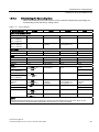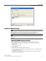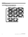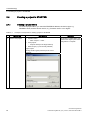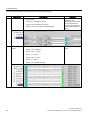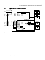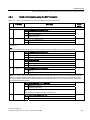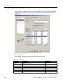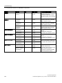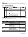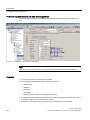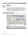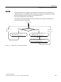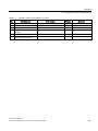
1
SINAMICS S120 Commissioning Manual · 01/2011 SINAMICS s Commissioning Manual ___________________ Preface Preparation for 1 ___________________ commissioning SINAMICS S120 Commissioning Manual Commissioning Manual Applies to: Firmware version 4.4 (IH1), 01/2011 6SL3097-4AF00-0BP1 2 ___________________ Commissioning 3 ___________________ Diagnostics A ___________________ Appendix Legal information Legal information Warning notice system This manual contains notices you have to observe in order to ensure your personal safety, as well as to prevent damage to property. The notices referring to your personal safety are highlighted in the manual by a safety alert symbol, notices referring only to property damage have no safety alert symbol. These notices shown below are graded according to the degree of danger. DANGER indicates that death or severe personal injury will result if proper precautions are not taken. WARNING indicates that death or severe personal injury may result if proper precautions are not taken. CAUTION with a safety alert symbol, indicates that minor personal injury can result if proper precautions are not taken. CAUTION without a safety alert symbol, indicates that property damage can result if proper precautions are not taken. NOTICE indicates that an unintended result or situation can occur if the corresponding information is not taken into account. If more than one degree of danger is present, the warning notice representing the highest degree of danger will be used. A notice warning of injury to persons with a safety alert symbol may also include a warning relating to property damage. Qualified Personnel The product/system described in this documentation may be operated only by personnel qualified for the specific task in accordance with the relevant documentation for the specific task, in particular its warning notices and safety instructions. Qualified personnel are those who, based on their training and experience, are capable of identifying risks and avoiding potential hazards when working with these products/systems. Proper use of Siemens products Note the following: WARNING Siemens products may only be used for the applications described in the catalog and in the relevant technical documentation. If products and components from other manufacturers are used, these must be recommended or approved by Siemens. Proper transport, storage, installation, assembly, commissioning, operation and maintenance are required to ensure that the products operate safely and without any problems. The permissible ambient conditions must be adhered to. The information in the relevant documentation must be observed. Trademarks All names identified by ® are registered trademarks of the Siemens AG. The remaining trademarks in this publication may be trademarks whose use by third parties for their own purposes could violate the rights of the owner. Disclaimer of Liability We have reviewed the contents of this publication to ensure consistency with the hardware and software described. Since variance cannot be precluded entirely, we cannot guarantee full consistency. However, the information in this publication is reviewed regularly and any necessary corrections are included in subsequent editions. Siemens AG Industry Sector Postfach 48 48 90026 NÜRNBERG GERMANY order number: 6SL3097-4AF00-0BP1 Ⓟ 01/2011 Copyright © Siemens AG 2007, 2008, 2009, 2011. Technical data subject to change Preface SINAMICS documentation The SINAMICS documentation is organized in the following categories: ● General documentation/catalogs ● User documentation ● Manufacturer/service documentation More information The following link provides information on the topics: ● Ordering documentation/overview of documentation ● Additional links to download documents ● Using documentation online (find and search in manuals/information) http://www.siemens.com/motioncontrol/docu Please send any questions about the technical documentation (e.g. suggestions for improvement, corrections) to the following e-mail address: [email protected] My Documentation Manager The following link provides information on how to create your own individual documentation based on Siemens' content, and adapt it for your own machine documentation: http://www.siemens.com/mdm Training The following link provides information on SITRAIN - training from Siemens for products, systems and automation engineering solutions: http://www.siemens.com/sitrain FAQs You can find Frequently Asked Questions in the Service&Support pages under Product Support. http://support.automation.siemens.com SINAMICS You can find information on SINAMICS at: http://www.siemens.com/sinamics. Commissioning Manual Commissioning Manual, (IH1), 01/2011, 6SL3097-4AF00-0BP1 3 Preface Usage phases and their tools/documents (as an example) Table 1 Usage phases and the available documents/tools Usage phase Document/tool Orientation SINAMICS S Sales Documentation Planning/configuration SIZER Configuration Tool Configuration Manuals, Motors Deciding/ordering SINAMICS S Catalogs Installation/assembly SINAMICS S120 Equipment Manual for Control Units and Additional System Components SINAMICS S120 Equipment Manual for Booksize Power Units SINAMICS S120 Equipment Manual for Chassis Power Units SINAMICS S120 Equipment Manual for AC Drives STARTER commissioning tool SINAMICS S120 Getting Started SINAMICS S120 Commissioning Manual SINAMICS S120 CANopen Commissioning Manual SINAMICS S120 Function Manual SINAMICS S120/S150 List Manual SINAMICS S120 Commissioning Manual SINAMICS S120/S150 List Manual SINAMICS S120 Commissioning Manual SINAMICS S120/S150 List Manual SINAMICS S120/S150 List Manual Commissioning Usage/operation Maintenance/servicing References Target group This documentation is intended for machine manufacturers, commissioning engineers, and service personnel who use the SINAMICS drive system. Benefits This Manual describes all the information, procedures and operational instructions required for commissioning and servicing SINAMICS S120. Commissioning Manual 4 Commissioning Manual, (IH1), 01/2011, 6SL3097-4AF00-0BP1 Preface Standard scope The scope of the functionality described in this document may differ from the scope of the functionality of the drive system that is actually supplied. ● It may be possible for other functions not described in this documentation to be executed in the drive system. However, no claim can be made regarding the availability of these functions when the equipment is first supplied or in the event of servicing. ● Functions that are not available in a particular product version of the drive system may be described in the documentation. The functionality of the supplied drive system should only be taken from the ordering documentation. ● Extensions or changes made by the machine manufacturer must be documented by the machine manufacturer. For reasons of clarity, this documentation does not contain all of the detailed information on all of the product types. This documentation cannot take into consideration every conceivable type of installation, operation and service/maintenance. Technical Support Country-specific telephone numbers for technical support are provided in the Internet under Contact: http://www.siemens.com/automation/service&support EC Declaration of Conformity The EC Declaration of Conformity for the EMC Directive can be found on the Internet at: http://support.automation.siemens.com There – as a search term – enter the number 15257461 or contact your local Siemens office. Notation The following notation and abbreviations are used in this documentation: Notation for parameters (examples): ● p0918 Adjustable parameter 918 ● r1024 Visualization parameter 1024 ● p1070[1] Adjustable parameter 1070, index 1 ● p2098[1].3 Adjustable parameter 2098, index 1, bit 3 ● p0099[0...3] Adjustable parameter 99, indices 0 to 3 ● r0945[2](3) Visualization parameter 945, index 2 of drive object 3 ● p0795.4 Adjustable parameter 795, bit 4 Notation for faults and alarms (examples): ● F12345 Fault 12345 ● A67890 Alarm 67890 Commissioning Manual Commissioning Manual, (IH1), 01/2011, 6SL3097-4AF00-0BP1 5 Preface ESD Notes CAUTION Electrostatic sensitive devices (ESD) are single components, integrated circuits or devices that can be damaged by electrostatic fields or electrostatic discharges. Regulations for the ESD handling: During the handling of electronic components, pay attention to the grounding of the person, workplace and packaging! Electronic components may be touched by persons only when these persons are grounded using an ESD bracelet, or these persons in ESD areas with a conducting floor wear ESD shoes or ESD grounding straps. Electronic components should be touched only when this is unavoidable. The touching is permitted only on the front panel or on the circuit board edge. Electronic components must not be brought into contact with plastics or clothing made of artificial fibers. Electronic components may only be placed on conducting surfaces (table with ESD coating, conducting ESD foamed material, ESD packing bag, ESD transport container). Electronic components may not be placed near display units, monitors or televisions (minimum distance from the screen > 10 cm). Measurements must only be taken on boards when the measuring instrument is grounded (via protective conductors, for example) or the measuring probe is briefly discharged before measurements are taken with an isolated measuring device (for example, touching a bare metal housing). Commissioning Manual 6 Commissioning Manual, (IH1), 01/2011, 6SL3097-4AF00-0BP1 Preface Safety notices DANGER Commissioning is absolutely prohibited until it has been completely ensured that the machine, in which the components described here are to be installed, is in full compliance with the provisions of the EC Machinery Directive. SINAMICS devices and AC motors may only be commissioned by suitably qualified personnel. The personnel must take into account the information provided in the technical customer documentation for the product, and be familiar with and observe the specified danger and warning notices. When electrical equipment and motors are operated, the electrical circuits automatically conduct a dangerous voltage. Dangerous mechanical movements are possible during system operations. All the work carried out on the electrical machine or system must be carried out with it in a no-voltage condition. SINAMICS devices with three-phase motors must only be connected to the power supply via a universal current-sensitive residual current operated device with selective switching once it has been verified that the SINAMICS device is compatible with the residual current operated device in accordance with IEC 61800-5-1. WARNING The successful and safe operation of this equipment and motors is dependent on professional transport, storage, installation and mounting as well as careful operations , service and maintenance. Information and data from the catalogs and quotations also apply to special versions of the equipment and motors. In addition to the danger and warning information provided in the technical customer documentation, the applicable national, local, and plant-specific regulations and requirements must be taken into account. Only protective extra-low voltages (PELV) that comply with EN60204-1 may be connected to all connections and terminals between 0 and 48 V. Commissioning Manual Commissioning Manual, (IH1), 01/2011, 6SL3097-4AF00-0BP1 7 Preface CAUTION The motors can have surface temperatures of over +80 °C. This is why temperature-sensitive components, e.g. cables or electronic components must not be in contact with or attached to the motor. When connecting up cables, please ensure that they – are not damaged – are not subject to tensile stress – cannot be touched by rotating components. CAUTION As part of routine tests, SINAMICS devices with three-phase motors undergo a voltage test in accordance with IEC 61800. Before the voltage test is performed on the electrical equipment of industrial machines to EN 60204-1, Section 18.4, all connectors of SINAMICS devices must be disconnected/withdrawn to prevent the equipment from being damaged. Motors should be connected up according to the circuit diagram provided otherwise they may be destroyed. CAUTION Terminals for pulse inhibit (EP terminals) The Safe Torque Off (STO) safety function must be parameterized in order to use the pulse inhibit terminals at the Motor Modules, booksize, booksize compact, chassis and Cabinet Modules and at the Power Modules, chassis and blocksize. (Safety Integrated Basic Functions or Extended Functions) Here, the procedure is described in the FHS and FH1 Function Manuals. Note When operated in dry areas, SINAMICS devices with three-phase motors conform to LowVoltage Directive 2006/95/EC. Commissioning Manual 8 Commissioning Manual, (IH1), 01/2011, 6SL3097-4AF00-0BP1 Contents Preface ...................................................................................................................................................... 3 1 2 Preparation for commissioning ................................................................................................................ 13 1.1 Requirements for commissioning.................................................................................................13 1.2 Check lists to commission SINAMICS S......................................................................................15 1.3 PROFIBUS components ..............................................................................................................18 1.4 PROFINET components ..............................................................................................................18 1.5 1.5.1 1.5.2 1.5.3 1.5.4 1.5.5 1.5.6 1.5.7 1.5.8 1.5.9 1.5.10 1.5.10.1 1.5.10.2 1.5.10.3 Rules for wiring with DRIVE-CLiQ ...............................................................................................20 Binding DRIVE-CLiQ rules...........................................................................................................20 Recommended DRIVE-CLiQ rules ..............................................................................................25 Wiring example for drives in vector control mode........................................................................29 Wiring example for parallel connection of Motor Modules in vector control mode ......................31 Sample wiring: Power Modules....................................................................................................32 Changing the offline topology in STARTER.................................................................................34 Offline correction of the reference topology.................................................................................35 Sample wiring for servo drives.....................................................................................................38 Sample wiring for vector V/f drives ..............................................................................................39 Notes on the number of controllable drives .................................................................................39 System sampling times and number of controllable drives .........................................................40 Optimizing DRIVE-CLiQ...............................................................................................................44 Default settings for the sampling times........................................................................................45 1.6 Powering-up/powering-down the drive system ............................................................................46 Commissioning ........................................................................................................................................ 51 2.1 2.1.1 Procedure when commissioning ..................................................................................................51 Safety guidelines..........................................................................................................................52 2.2 2.2.1 2.2.2 2.2.3 2.2.4 STARTER commissioning tool.....................................................................................................53 Important STARTER functions.....................................................................................................53 Activating online operation: STARTER via PROFIBUS...............................................................55 Activating online operation: STARTER via Ethernet....................................................................56 Activating online operation: STARTER via PROFINET IO ..........................................................60 2.3 2.3.1 2.3.1.1 2.3.1.2 2.3.1.3 2.3.1.4 2.3.2 Basic Operator Panel 20 (BOP20)...............................................................................................65 Operation with BOP20 (Basic Operator Panel 20) ......................................................................65 General information about the BOP20.........................................................................................65 Displays and using the BOP20 ....................................................................................................70 Fault and alarm displays ..............................................................................................................75 Controlling the drive using the BOP20.........................................................................................76 Important functions via BOP20 ....................................................................................................77 2.4 2.4.1 2.4.2 Creating a project in STARTER ...................................................................................................78 Creating a project offline ..............................................................................................................78 Searching for a drive unit online ..................................................................................................80 2.5 First commissioning, servo control mode, booksize format.........................................................82 Commissioning Manual Commissioning Manual, (IH1), 01/2011, 6SL3097-4AF00-0BP1 9 Contents 3 2.5.1 2.5.2 2.5.3 2.5.4 Task............................................................................................................................................. 83 Component wiring (example) ...................................................................................................... 84 Signal flow of the commissioning example ................................................................................. 85 Commissioning with STARTER (example) ................................................................................. 86 2.6 2.6.1 2.6.2 2.6.3 2.6.4 First commissioning control mode vector U/f in booksize format................................................ 89 Task............................................................................................................................................. 89 Component wiring (example) ...................................................................................................... 90 Signal flow of the commissioning example ................................................................................. 91 Commissioning with STARTER (example) ................................................................................. 92 2.7 2.7.1 2.7.2 2.7.3 2.7.4 First commissioning, vector control mode in the chassis format ................................................ 96 Task............................................................................................................................................. 97 Component wiring (example) ...................................................................................................... 98 Signal flow of the commissioning example ................................................................................. 99 Commissioning with STARTER (example) ............................................................................... 100 2.8 2.8.1 2.8.2 2.8.3 First commissioning, control mode vector AC Drive in the booksize format............................. 105 Task........................................................................................................................................... 105 Component wiring (example) .................................................................................................... 106 Quick commissioning using the BOP (example)....................................................................... 107 2.9 2.9.1 2.9.2 2.9.3 2.9.4 First commissioning, control mode servo AC Drive in the booksize format.............................. 110 Initial commissioning using servo (booksize) as an example_lead text.................................... 110 Task........................................................................................................................................... 110 Component wiring (example) .................................................................................................... 111 Quick commissioning using the BOP (example)....................................................................... 112 2.10 Commissioning of power units connected in parallel................................................................ 114 2.11 Learn devices............................................................................................................................ 119 2.12 Selection and configuration of encoders................................................................................... 120 2.13 2.13.1 2.13.2 2.13.3 2.13.4 2.13.5 2.13.6 Commissioning linear motors (servo) ....................................................................................... 130 General information on commissioning linear motors............................................................... 130 Commissioning: Linear motor with one primary section ........................................................... 133 Commissioning: Linear motor with several identical primary sections ..................................... 137 Thermal motor protection .......................................................................................................... 138 Measuring system ..................................................................................................................... 141 Checking the linear motor by taking measurements................................................................. 144 2.14 Notes on commissioning SSI encoders .................................................................................... 146 2.15 Notes on the commissioning of a 2-pole resolver as absolute encoder ................................... 150 2.16 Temperature sensors for SINAMICS components ................................................................... 151 Diagnostics ............................................................................................................................................ 159 3.1 3.1.1 3.1.1.1 3.1.1.2 3.1.1.3 3.1.1.4 3.1.1.5 3.1.1.6 3.1.1.7 Diagnostics via LEDs ................................................................................................................ 159 Control Units ............................................................................................................................. 159 Description of the LED states of a CU 320-2 ............................................................................ 159 Control Unit 320-2DP during booting ........................................................................................ 160 Control Unit 320-2DP in operation ............................................................................................ 161 Control Unit 320-2PN while booting.......................................................................................... 163 Control Unit 320-2PN in operation ............................................................................................ 164 Description of the LED states of a CU 310-2 ............................................................................ 166 Control Unit 310-2DP during booting ........................................................................................ 167 Commissioning Manual 10 Commissioning Manual, (IH1), 01/2011, 6SL3097-4AF00-0BP1 Contents 3.1.1.8 3.1.1.9 3.1.1.10 3.1.2 3.1.2.1 3.1.2.2 3.1.2.3 3.1.2.4 3.1.2.5 3.1.2.6 3.1.2.7 3.1.2.8 3.1.2.9 3.1.2.10 3.1.2.11 3.1.2.12 3.1.2.13 3.1.2.14 3.1.2.15 3.1.2.16 3.1.2.17 3.1.2.18 3.1.3 3.1.3.1 3.1.3.2 3.1.3.3 3.1.3.4 3.1.3.5 3.1.3.6 3.1.3.7 3.1.3.8 3.1.3.9 3.1.4 3.1.4.1 3.1.4.2 3.1.4.3 3.1.4.4 3.1.4.5 Control Unit 310-2DP in operation.............................................................................................168 Control Unit 310-2PN while booting...........................................................................................169 Control Unit 310-2PN in operation.............................................................................................170 Power units ................................................................................................................................171 Active Line Module booksize .....................................................................................................171 Basic Line Module booksize ......................................................................................................172 Smart Line Modules booksize 5 kW and 10 kW ........................................................................173 Smart Line Modules booksize 16 kW to 55 kW .........................................................................174 Single Motor Module / Double Motor Module / Power Module ..................................................175 Braking Modules booksize format..............................................................................................176 Smart Line Module booksize compact format............................................................................176 Motor Module booksize compact format....................................................................................178 Control Interface Module in the Active Line Module chassis format..........................................179 Control Interface Board in the Active Line Module chassis format ............................................180 Control Interface Module in the Basic Line Module chassis format...........................................181 Control Interface Board in the Basic Line Module chassis format .............................................182 Control Interface Module in the Smart Line Module chassis format ..........................................183 Control Interface Board in the Smart Line Module chassis format ............................................184 Control Interface Module in the Motor Module chassis format ..................................................185 Control Interface Board in the Motor Module chassis format ....................................................186 Control Interface Module in the Power Module chassis format .................................................187 Control Interface Board in the Power Module chassis format ...................................................188 Additional modules.....................................................................................................................189 Control Supply Module...............................................................................................................189 Meaning of the LEDs on the Control Interface Module in the Power Module............................190 Meaning of the LEDs on the Control Interface Board in the Power Module..............................191 Sensor Module Cabinet SMC10 / SMC20 .................................................................................192 Meaning of LEDs on the Sensor Module Cabinet-Mounted SMC30 .........................................193 Communication Board CBC10 for CANopen.............................................................................194 Communication Board Ethernet CBE20 ....................................................................................195 Voltage Sensing Module VSM10 ...............................................................................................197 DRIVE-CLiQ Hub Module DMC20 .............................................................................................198 Terminal Module ........................................................................................................................199 Terminal Module TM15 ..............................................................................................................199 Terminal Module TM31 ..............................................................................................................200 Terminal Module TM41 ..............................................................................................................201 Terminal Module TM54F............................................................................................................202 Terminal Module TM120 ............................................................................................................204 3.2 3.2.1 3.2.2 3.2.3 3.2.4 Diagnostics via STARTER .........................................................................................................205 Function generator.....................................................................................................................205 Trace function ............................................................................................................................209 Measuring function.....................................................................................................................211 Measuring sockets .....................................................................................................................213 3.3 Diagnostic buffer ........................................................................................................................217 3.4 Diagnostics of uncommissioned axes........................................................................................221 3.5 3.5.1 3.5.2 3.5.3 3.5.4 Fault and alarm messages.........................................................................................................224 General information about faults and alarms.............................................................................224 Buffer for faults and alarms........................................................................................................226 Configuring messages ...............................................................................................................230 Parameters and function diagrams for faults and alarms ..........................................................232 Commissioning Manual Commissioning Manual, (IH1), 01/2011, 6SL3097-4AF00-0BP1 11 Contents A 3.5.5 3.5.6 Forwarding of faults................................................................................................................... 233 Alarm classes............................................................................................................................ 234 3.6 Troubleshooting for encoders ................................................................................................... 235 Appendix................................................................................................................................................ 239 A.1 Availability of hardware components ........................................................................................ 239 A.2 List of abbreviations .................................................................................................................. 242 Index...................................................................................................................................................... 253 Commissioning Manual 12 Commissioning Manual, (IH1), 01/2011, 6SL3097-4AF00-0BP1 Preparation for commissioning 1 Before commissioning observe the conditions described in this chapter. ● The preconditions for commissioning must be fulfilled (in the next chapter). ● The relevant checklist must have been worked through. ● The bus components required for communication must be wired up. ● DRIVE-CliQ wiring rules must be adhered to. ● ON-OFF responses of the drive 1.1 Requirements for commissioning The following are necessary for commissioning a SINAMICS S drive system: ● STARTER commissioning tool ● An interface, e.g. PROFIBUS, PROFINET, CAN bus or USS (RS232-C) ● Completely wired-up drive line-up (see the Manual) The following diagram shows a sample configuration with booksize and chassis components. Commissioning Manual Commissioning Manual, (IH1), 01/2011, 6SL3097-4AF00-0BP1 13 Preparation for commissioning 1.1 Requirements for commissioning ; ; &RQWURO 8QLW ; $FWLYH /LQH 0RGXOH 6LQJOH 0RWRU 0RGXOH ; 3&3* ; 60& ; 352),%86 ; &RQWURO 8QLW ; $FWLYH ,QWHUIDFH 0RGXOH ;; $FWLYH /LQH 0RGXOH ; 6LQJOH 0RWRU 0RGXOH 3&3* ; 352),%86 Figure 1-1 Component configuration (example) Commissioning Manual 14 Commissioning Manual, (IH1), 01/2011, 6SL3097-4AF00-0BP1 Preparation for commissioning 1.2 Check lists to commission SINAMICS S 1.2 Check lists to commission SINAMICS S Checklist (1) for commissioning booksize power units The following checklist must be carefully observed. Read the safety instructions in the Manuals before starting any work. Table 1- 1 Checklist for commissioning (booksize) Check OK Are the environmental conditions in the permissible range? Is the component firmly attached to the fixing points provided? Is the specified air flow for cooling the devices ensured? Have the ventilation clearances for the components been observed? Is the memory card correctly inserted in the Control Unit? Are all of the necessary components of the configured drive line-up available, installed and connected? Do the temperature monitoring circuits fulfill the specifications of protective separation? Have the DRIVE-CLiQ topology rules been observed? Have the line-side and motor-side power cables been dimensioned and routed in accordance with the environmental and routing conditions? Have the maximum permissible cable lengths between the frequency converter and the motor (depending on the type of cables used) been observed? Have the power cables been properly connected to the component terminals with the specified torque? Have all of the remaining screws been tightened to the specified torque? Has all wiring work been successfully completed? Are all connectors correctly plugged in and screwed in place? Have all the covers for the DC link been closed and latched into place? Have the screens been correctly connected through a large surface area? Commissioning Manual Commissioning Manual, (IH1), 01/2011, 6SL3097-4AF00-0BP1 15 Preparation for commissioning 1.2 Check lists to commission SINAMICS S Checklist (2) for commissioning chassis power units The following checklist must be carefully observed. Read the safety instructions in the Manuals before starting any work. Table 1- 2 Checklist for commissioning (chassis) Activity OK Are the environmental conditions in the permissible range? Are the components correctly installed in the cabinets? Is the specified air flow for cooling the devices ensured? Is an air short-circuit between the air inlet and outlet for the chassis components prevented by the installation arrangements? Have the ventilation clearances for the components been observed? Is the memory card correctly inserted in the Control Unit? Are all of the necessary components of the configured drive line-up available, installed and connected? Do the temperature monitoring circuits fulfill the specifications of protective separation? Have the DRIVE-CLiQ topology rules been observed? Have the line-side and motor-side power cables been dimensioned and routed in accordance with the environmental and routing conditions? Have the maximum permissible cable lengths between the frequency converter and the motor (depending on the type of cables used) been observed? Is the ground for the motors directly connected to the ground for the Motor Modules (shortest distance)? Are the motors connected with shielded power cables? Are the power cable shields connected as closely as possible to the terminal box across a wide area? Have the power cables been properly connected to the component terminals with the specified torque? Have all of the remaining screws been tightened to the specified torque? Has the total power of the DC busbar been dimensioned sufficiently? Has the busbar/wiring for the DC connection between the infeed and the Motor Modules been dimensioned sufficiently with regard to the load and installation conditions? Are the cables between the low-voltage switchgear and the power unit protected with line fuses? Line protection(1) should be taken into account. Have measures been taken to relieve strain on the cables? For external auxiliary infeed: Have the cables for the auxiliary infeed been connected according to the Equipment Manual? Have the control cables been connected in accordance with the required interface configuration and the shield applied? Have the digital and analog signals been routed with separate cables? Has the distance from power cables been observed? Has the cabinet been properly grounded at the points provided? Has the connection voltage for the fans in the chassis components been adapted accordingly to the supply voltages? Commissioning Manual 16 Commissioning Manual, (IH1), 01/2011, 6SL3097-4AF00-0BP1 Preparation for commissioning 1.2 Check lists to commission SINAMICS S Activity OK For operation on non-grounded supply systems: Has the connection bracket for the interference suppression at the Infeed Module or the Power Module been removed? Is the period from the date of manufacture to initial commissioning or the downtime of the power components less than two years(2)? Is the drive operated by higher-level controller/control room? Checklist (3) for commissioning blocksize Power Modules The following checklist must be carefully observed. Read the safety instructions in the Manuals before starting any work. Table 1- 3 Check list for commissioning blocksize Check OK Are the environmental conditions in the permissible range? Is the component firmly attached to the fixing points provided? Is the specified air flow for cooling the devices ensured? Have the ventilation clearances for the components been observed? Is the memory card correctly inserted in the Control Unit? Are all of the necessary components of the configured drive line-up available, installed and connected? Do the temperature monitoring circuits fulfill the specifications of protective separation? Have the line-side and motor-side power cables been dimensioned and routed in accordance with the environmental and routing conditions? Have the maximum permissible cable lengths between the frequency converter and the motor (depending on the type of cables used) been observed? Have the power cables been properly connected to the component terminals with the specified torque? Have all of the remaining screws been tightened to the specified torque? Has all wiring work been successfully completed? Are all connectors correctly plugged in and screwed in place? Have the screens been correctly connected through a large surface area? Combined fuses are recommended for conductor and semi-conductor protection (VDE 636, Part 10 and Part 40 / EN 60269-4). For information about the relevant fuses, see the catalog. (1) (2)If the downtime period is longer than two years, the DC link capacitors must be reformed (see the "Maintenance and Servicing" chapter in the Equipment Manual). If the device has been non-operational for less than two years, reforming is not necessary. The cabinet rating plate can be used to ascertain the date of manufacture. Commissioning Manual Commissioning Manual, (IH1), 01/2011, 6SL3097-4AF00-0BP1 17 Preparation for commissioning 1.3 PROFIBUS components 1.3 PROFIBUS components For communication via PROFIBUS, components with a PROFIBUS interface are required. ● A communication module for programming device/PC connection via the PROFIBUS interface: ● PROFIBUS connection to a programming device/PC via USB port (USB V2.0), e.g. with the PROFIBUS adapter CP5711. Structure: USB port (USB V2.0) + adapter with 9-pin SUB-D socket connector to connect to PROFIBUS. Used with driver SIMATIC Net PC Software Edition 2008 + SP2 Order No.: 6GK1571-1AA00 Connecting cable Connecting cable between PROFIBUS adapter and programming device/PC, such as ● Between CP 5xxx and PROFIBUS, Order No.: 6ES7901-4BD00-0XA0 ● MPI cable (SIMATIC S7), Order No.: 6ES7901-0BF00-0AA0 Cable lengths Table 1- 4 Permissible PROFIBUS cable lengths Baud rate [bit/s] 1.4 Max. cable length [m] 9.6 k to 187.5 k 1000 500 k 400 1.5 M 200 3 to 12 M 100 PROFINET components For communication via PROFINET, components with a PROFINET interface are required: 1. A communication module for programming device/PC connection via the PROFINET interface. Commissioning Manual 18 Commissioning Manual, (IH1), 01/2011, 6SL3097-4AF00-0BP1 Preparation for commissioning 1.4 PROFINET components Note For commissioning with STARTER, the onboard Ethernet interface of the Control Unit can be used with a crossover cable from CAT5 and higher. The PROFINET module CBE20 supports all standard Ethernet cables and crossover cables from CAT5/5e and higher. 2. Connecting cable Connecting cable between PROFINET adapter and programming device/PC, such as – Industrial Ethernet FC TP Standard Cable GP 2 x 2 (up to max. 100 m) Standard bus cable with rigid conductors and a special design for fast installation Order No.: 6XV1840-2AH10 – Industrial Ethernet FC TP Flexible Cable GP 2 x 2 (up to max. 85 m) Order No.: 6XV1870–2B – Industrial Ethernet FC Trailing Cable GP 2 x 2 (up to max. 85 m) Order No.: 6XV1870–2D – Industrial Ethernet FC Trailing Cable 2 x 2 (up to max. 85 m) Order No.: 6XV1840–3AH10 – Industrial Ethernet FC Marine Cable 2 x 2 (up to max. 85 m) Order No.: 6XV1840–4AH10 3. Connector Connector between PROFINET adapter and PG/PC, such as – Industrial Ethernet FC RJ45 Plug 145 for Control Unit Order No.: 6GK1901-1BB30-0Ax0 Commissioning Manual Commissioning Manual, (IH1), 01/2011, 6SL3097-4AF00-0BP1 19 Preparation for commissioning 1.5 Rules for wiring with DRIVE-CLiQ 1.5 Rules for wiring with DRIVE-CLiQ Rules apply for wiring components with DRIVE-CLiQ. A distinction is made between binding DRIVE-CLiQ rules, which must be unconditionally observed and recommended rules, whichshould then be maintained so that the topology, generated offline in STARTER, no longer has to be changed. The maximum number of DRIVE-CLiQ components and the possible wiring type depend on the following factors: ● The binding DRIVE-CLiQ wiring rules ● The number and type of activated drives and functions on the Control Unit in question ● The computing power of the Control Unit in question ● The set processing and communication cycles Below you will find the binding wiring rules and some other recommendations as well as a few sample topologies for DRIVE-CLiQ wiring. The components used in these examples can be removed, replaced with others or supplemented. If components are replaced by another type or additional components are added, the SIZER tool should be used to check the topology. If the actual topology does not match the topology created offline by STARTER, the offline topology must be changed accordingly before it is downloaded. 1.5.1 Binding DRIVE-CLiQ rules DRIVE-CLiQ rules The wiring rules below apply to standard cycle times (servo 125 µs, vector 250 µs). For cycle times that are shorter than the corresponding standard cycle times, additional restrictions apply due to the computing power of the Control Unit (configured using the SIZER configuration tool). General DRIVE-CLiQ rules The following general binding DRIVE-CLiQ rules must be observed to ensure safe operation of the drive. 1. A maximum of 14 DRIVE-CLiQ nodes can be connected to one DRIVE-CLiQ line at a Control Unit (e. g. 12 U/f axes + Infeed Module + 1 additional module). In the example below, the DRIVE-CLiQ line includes drive objects 1 to 14. 2. It is permissible to connect a maximum total of 8 Motor Modules to the Control Unit. For multi-axis modules, each axis counts individually (1 Double Motor Module = 2 Motor Modules). Exception: For U/f control it is permissible to connect a maximum of 12 Motor Modules. 3. With vector U/f control, it is only permissible to connect more than 4 participants to one DRIVE-CLiQ line of the Control Unit. 4. Ring wiring of components is not permitted. Commissioning Manual 20 Commissioning Manual, (IH1), 01/2011, 6SL3097-4AF00-0BP1 Preparation for commissioning 1.5 Rules for wiring with DRIVE-CLiQ 5. Double wiring of components is not permitted. &RQWURO 8QLW ; ; ; ; 1R GRXEOHZLULQJ Figure 1-2 1R ULQJZLULQJ Example: DRIVE-CLiQ line connected to the X103 DRIVE-CLiQ connection of a Control Unit 6. DRIVE-CLiQ components of unknown type within a topology are functionally not supported. The DRIVE-CLiQ signals are looped through. The following criteria denote the unknown type: – Characteristics of the component are not available. – A deputy drive object is not defined. – An assignment of the component to a known drive object is not defined. 7. In a DRIVE-CLiQ topology with a CU link and DRIVE-CLiQ connections, precisely one Control Unit is permissible as a CU link master/DRIVE-CLiQ master. 8. If a CU link connection is detected, the DRIVE-CLiQ basic clock cycle 0 (r0110[0]) is set to 125 μs and assigned to this DRIVE-CLiQ socket. 9. The following applies for booksize format: – In the servo control and vector U/f control operating modes, only one Line Module may be connected to the Control Unit. In the vector control operating mode, a maximum of three further Line Modules may be connected in parallel (i.e. at total of 4 Line Modules). – One Line Module and Motor Modules can be connected to one DRIVE-CLiQ line in the servo control mode. – One Line Module and Motor Modules must be connected to separate DRIVE-CLiQ lines in the vector control mode. – For booksize format, a parallel connection of Infeed Modules or Motor Modules is not possible. 10.The following applies for chassis format: – Line Modules (Active Line, Basic Line, Smart Line) and Motor Modules must be connected to separate DRIVE-CLiQ lines. – Motor Modules with different pulse frequencies (frame sizes FX, GX, HX, JX) must be connected to separate DRIVE-CLiQ lines. Commissioning Manual Commissioning Manual, (IH1), 01/2011, 6SL3097-4AF00-0BP1 21 Preparation for commissioning 1.5 Rules for wiring with DRIVE-CLiQ 11.Parallel operation of power units in chassis format: – A parallel connection of power units is permissible for vector control and U/f control but not for servo control. – A maximum of 4 Infeed Modules are permissible within a parallel connection. – A maximum of 4 Motor Modules are permissible within a parallel connection. – Only just one parallel connection of Motor Modules is permissible. For a parallel connection, exactly one drive object ("Servo" or "Vector") is created in the topology. 12.For parallel connection of Motor Modules, only one SINAMICS Sensor Module Integrated (SMI) is permitted for each Motor Module. 13.Switchover between different motors is not permitted for a parallel connection. 14.Mixed operation of Infeed Modules or Motor Modules: – The operation of Infeed Modules or Motor Modules with different performance values is not permitted within a parallel connection. – For Line Modules in chassis format, two parallel connections are permissible for mixed operation of Smart Line Modules and Basic Line Modules. – The following combinations of Line Modules are not permissible: Active Line Module (ALM) with Basic Line Module (BLM) Active Line Module (ALM) with Smart Line Module (SLM) 15.Mixed operation of formats: – Chassis Motor Modules and booksize Motor Modules must be connected to separate DRIVE-CLiQ lines. 16.Mixed operation of control types: – Mixed operation of servo control and vector control is not permissible. – Mixed operation of servo control and U/f control is permissible. – Mixed operation of vector control and U/f control is permissible. 17.Mixed operation of control cycles: The following combinations are permissible: – Servo with 62.5 µs and servo with 125 µs – Servo with 125 µs and servo with 250 µs – Vector with 250 µs and vector with 500 µs 18.Operation with Voltage Sensing Module (VSM): – Exactly 1 Voltage Sensing Module (VSM) may be connected to one Line Module. Exception: If the "Transformer" function module is activated, a second VSM may be connected. – A maximum of 2 VSMs may be connected to one Motor Module. – The VSM must be connected to a free DRIVE-CLiQ socket of the associated Line Modules/Motor Modules (to support automatic assignment of the VSM). Commissioning Manual 22 Commissioning Manual, (IH1), 01/2011, 6SL3097-4AF00-0BP1 Preparation for commissioning 1.5 Rules for wiring with DRIVE-CLiQ 19.At a "SERVO" or "VECTOR" drive object, the number of connected encoders must be equal to the number of parameterized encoder data sets (p0140). A maximum of three encoders are permissible per drive object. Exception: – For a maximum quantity structure of 6 axes in servo control with a controller cycle of 125 μs and one Line Module, a maximum of 9 encoders can be connected. – For 5 axes in servo control with a controller cycle of 125 μs, a maximum of 15 encoders can be connected. 20.A maximum of up to 24 drive objects can be connected. 21.A maximum of 16 Terminal Modules can be connected to the CU320-2. Note: If a TM15 Base, TM31, TM54F or a TM41 is connected, it is necessary to reduce the number of connected standard axes. 22.Cycle times with TM31 A maximum of 3 Terminal Modules 31 (TM31) can be connected for a 2 ms time slice. Note A Double Motor Module, one DMC20, one DME20, one TM54F and one CUA32 each correspond to two DRIVE-CLiQ participants. This also applies to Double Motor Modules, at which just one drive is configured. 23.The communication basic clock cycles (p0115[0] and p4099) of all components that are connected to a DRIVE-CLiQ line must be divisible by one another with an integer result. – The smallest communication basic clock cycle is 125 µs. – The exception are a maximum of 3 servo-controlled axes with 62.5 µs communication basic clock cycle or a servo-controlled axis with 31.25 µs communication basic clock cycle. 24.For current controller clock cycles Ti < 125 μs, the Motor Modules - also with the same controller clock cycle - must be symmetrically connected to two DRIVE-CLiQ ports. 25.The fastest sampling time of a drive object in servo control mode is given as: – Ti = 31.25 µs: Exactly 1 drive object in servo control – Ti = 62.5 µs: Max. 3 drive objects in servo control – Ti = 125 µs: Max. 6 drive objects in servo control 26.The fastest sampling time of a drive object in vector control mode is given as: – Ti = 250 µs: Max. 3 drive objects in vector control – Ti = 400 µs: Max. 5 drive objects in vector control – Ti = 500 µs: Max. 6 drive objects in vector control 27.The fastest sampling time of a drive object in vector U/f vector control mode is given as: – Ti = 500 µs: Max. 12 drive objects in U/f control mode Commissioning Manual Commissioning Manual, (IH1), 01/2011, 6SL3097-4AF00-0BP1 23 Preparation for commissioning 1.5 Rules for wiring with DRIVE-CLiQ 28.The maximum number of DRIVE-CLiQ nodes on a DRIVE-CLiQ line of the Control Unit depends on the basic clock cycle of the DRIVE-CLiQ line: – For a current controller cycle of 31.25 µs, a maximum of 3 DRIVE-CLiQ nodes are permissible – For a current controller cycle of 62.5 µs, a maximum of 5 DRIVE-CLiQ nodes are permissible – For a current controller cycle of 125 µs, a maximum of 14 DRIVE-CLiQ nodes are permissible – For a current controller cycle of 250 µs, a maximum of 20 DRIVE-CLiQ nodes are permissible – For a current controller cycle of 500 µs, a maximum of 30 DRIVE-CLiQ nodes are permissible 29.Examples for clock cycle level 62.5 µs: – Topology 1: 1 x ALM (250 µs) + 2 x servo (62.5 µs) + 2 x servo (125 µs) + 3 x TM15 + TM54F + 4 x dbSI2 with encoder SI Motion monitoring clock cycle (p9500) = 12 ms + SI Motion actual value sensing clock cycle (p9511) = 4 ms + 4 x dir. measuring systems – Topology 2: 1 x ALM (250 µs) + 2 x servo (62.5 µs) + 2 x U/f (500 µs) + 3 x TM15 Base 2 ms +2 x dbSI2 with encoder SI Motion monitoring clock cycle (p9500) = 12 ms + SI Motion actual value sensing clock cycle (p9511) = 4 ms + 2 x dbSI2 sensorless + 2 x dir. measuring systems – Topology 3: 1 x servo (62.5 μs) + 4 x U/f is not possible in connection with Safety Integrated. 30.Examples for clock cycle level 31.25 µs: 1 x servo (31.25 µs) 31.If the current controller sampling time Ti at one drive object has to be changed in a sampling time that does not match the other drive objects in the DRIVE-CLiQ line, the following solutions are available: – Insert the modified drive object into a separate DRIVE-CLiQ line. – Modify the current controller sampling times and/or the sampling times of the inputs/outputs of the other drive objects in the same way, so that they match the modified sampling time again. 32.Only components that have the same sampling time may be be connected to free DRIVECLiQ connections with a sampling time of Ti = 31.25 μs. The following components are permissible: – Sensor Modules – High-frequency damping modules (HF damping modules) – Active Line Modules Booksize in the line of the HF filter module. – Smart Line Modules Booksize in the line of the HF filter module. – Additional DRIVE-CLiQ lines must be used for further components: Further Motor Modules in servo control, in vector control, in U/f control or TMs. Commissioning Manual 24 Commissioning Manual, (IH1), 01/2011, 6SL3097-4AF00-0BP1 Preparation for commissioning 1.5 Rules for wiring with DRIVE-CLiQ 33.Connection of the following components is not permissible for a sampling time of Ti = 31.25 μs: – Further Motor Modules in servo control. – Further Motor Modules in U/f control. 34.Rules for using a TM54F: – A TM54F must be connected directly to a Control Unit via DRIVE-CLiQ. – Only one TM54F Terminal Module can be assigned to each Control Unit. – Additional DRIVE-CLiQ nodes can be operated at the TM54F, such as Sensor Modules and Terminal Modules (excluding an additional TM54F). – For a CU310-2, no TM54F may be connected to the same DRIVE-CLiQ line as the Power Module. 35.A maximum of 4 Motor Modules with Safety Extended Functions may be operated on one DRIVE-CLiQ line (only for TI = 125 μs). Additional DRIVE-CLiQ components may not be connected to this DRIVE-CLiQ line. 36.If an axis has only one encoder, and if Safety functions are activated for this axis, then this encoder may be connected to the Motor Module or to the Hub Module DMC20 only. 37.The following applies to the DRIVE-CLiQ connection of CX/NX components to a Control Unit: The connection to the Control Unit is obtained from the PROFIBUS address of the CX/NX (10 → X100, 11 → X101, 12 → X102, 13 → X103, 14 → X104, 15 → X105). 38.It is not permissible to combine SIMOTION Master Control Units and SINUMERIK Slave Control Units. 39.It is not permissible to combine SINUMERIK Master Control Units and SIMOTION Slave Control Units. Note To enable the function "Automatic configuration" to assign the encoders to the drives, the recommended rules below must also be observed. 1.5.2 Recommended DRIVE-CLiQ rules Recommended DRIVE-CLiQ rules 1. The following applies to all DRIVE-CLiQ components with the exception of the Control Unit: The DRIVE-CLiQ sockets Xx00 are DRIVE-CliQ inputs, the other DRIVE-CLiQ sockets are outputs. Commissioning Manual Commissioning Manual, (IH1), 01/2011, 6SL3097-4AF00-0BP1 25 Preparation for commissioning 1.5 Rules for wiring with DRIVE-CLiQ 2. A single Line Module should be connected directly to the X100 DRIVE-CLiQ socket of the Control Unit. – Several Line Modules should be connected in a line. – If the X100 DRIVE-CLiQ socket is not available, the next higher DRIVE-CLiQ socket should be used. 3. For a current controller cycle of 31.25 μs, a filter module should be directly connected to a DRIVE-CLiQ socket of the Control Unit. 4. For the chassis format, Motor Modules with a current controller cycle of 250 μs should be connected to DRIVE-CLiQ socket X101 of the Control Unit. If required, they should be connected in a line. – If the DRIVE-CLiQ socket X101 is not available, the next higher DRIVE-CLiQ socket should be used for these Motor Modules. 5. For the chassis format, Motor Modules with a current controller cycle of 400 μs should be connected to DRIVE-CLiQ socket X102 of the Control Unit. If required, they should be connected in a line. – If the DRIVE-CLiQ socket X102 is not available, the next higher DRIVE-CLiQ socket should be used for these Motor Modules. 6. For the chassis format, the Line Module and the Motor Modules should be connected to separate DRIVE-CLiQ lines. 7. Peripheral components (e.g. Terminal Module, TM) should be connected to DRIVE-CLiQ socket X103 of the Control Unit in a line. – If the DRIVE-CLiQ socket X103 is not available, any free DRIVE-CLiQ socket should be selected for the peripheral components. 8. For the booksize format, the Motor Modules in servo control mode should be connected in line to DRIVE-CLiQ socket X100 of the Control Unit. – If the DRIVE-CLiQ socket X100 is not available, the next higher DRIVE-CLiQ socket should be used for these Motor Modules. 9. The motor encoders for the first drive of a Double Motor Module should be connected to the associated DRIVE-CLiQ socket X202. 10.The motor encoders for the second drive of a Double Motor Module should be connected to the associated DRIVE-CLiQ socket X203. Commissioning Manual 26 Commissioning Manual, (IH1), 01/2011, 6SL3097-4AF00-0BP1 Preparation for commissioning 1.5 Rules for wiring with DRIVE-CLiQ 11.The motor encoder should be connected to the associated Motor Module: Connecting the motor encoder via DRIVE-CLiQ: – Single Motor Module Booksize to terminal X202 – Double Motor Module Booksize motor X1 to terminal X202 and motor X2 to terminal X203 – Single Motor Module Chassis to terminal X402 – Power Module Blocksize with CUA31: Encoder to terminal X202 – Power Module Blocksize with CUA31: Encoder to terminal X100 or via TM31 to X501 – Power Module Chassis to terminal X402 Note If an additional encoder is connected to a Motor Module, it is assigned to this drive as encoder 2 in the automatic configuration. 12.DRIVE-CLiQ sockets should, as far as possible, be symmetrically wired. Example: Do not connect 8 DRIVE-CLiQ nodes in series at one DRIVE-CLiQ socket of the CU - but instead, connect 2 nodes at each of the 4 DRIVE-CLiQ sockets. 13.The DRIVE-CLiQ cable from the Control Unit should be connected to DRIVE-CLiQ socket X200 on the first booksize power unit or X400 on the first chassis power unit. 14.The DRIVE-CLiQ connections between the power units should each be connected from the DRIVE-CLiQ sockets X201 to X200 and/or X401 to X400 on the follow-on component. 15.A Power Module with the CUA31 should be connected to the end of the DRIVE-CLiQ line. &RQWURO 8QLW 6LQJOH 0RWRU 0RGXOH 'RXEOH 0RWRU 0RGXOH 6LQJOH 0RWRU 0RGXOH ;; ; ;; ; ;; ; ;; ; ;; ; ;; 3RZHU0RGXOH %ORFNVL]H ; ; ; Figure 1-3 &8$ ; ; ; Example: DRIVE-CLiQ line 16.Only one final node should be connected to free DRIVE-CLiQ sockets of components within a DRIVE-CLiQ line (e.g. Motor Modules wired in series), for example, one Sensor Module or one Terminal Module, without routing to additional components. 17.If possible, Terminal Modules and Sensor Modules of direct measuring systems should not be connected to the DRIVE-CLiQ line of Motor Modules, but rather, to free DRIVECLiQ sockets of the Control Unit. Note: This restriction does not apply to star-type connections. 18.The TM54F should not be operated on the same DRIVE-CLiQ line as Motor Modules. Commissioning Manual Commissioning Manual, (IH1), 01/2011, 6SL3097-4AF00-0BP1 27 Preparation for commissioning 1.5 Rules for wiring with DRIVE-CLiQ 19.The Terminal Modules TM15, TM17 and TM41 have faster sample cycles than the TM31 and TM54F. For this reason, the two Terminal Module groups should be connected to separate DRIVE-CLiQ lines. 20.For mixed operation of the servo control and vector U/f control operating modes, separate DRIVE-CLiQ lines should be used for the Motor Modules. – Mixed operation of operating modes is not possible on a Double Motor Module. 21.The Voltage Sensing Module (VSM) should be connected to the DRIVE-CLiQ socket X202 (Booksize format) or X402 (Chassis format) of the Line Module. – If the X202/X402 DRIVE-CLiQ sockets are not available, a free DRIVE-CLiQ socket of the Line Module should be used. &RQWURO 8QLW $FWLYH /LQH 0RGXOH 6LQJOH 0RWRU 0RGXOH ; ; ;; ; ;; ; ;; ; ;; ;; 960 ;; Figure 1-4 Example of a topology with VSM for booksize and chassis components Table 1- 5 VSM connection Component VSM connection Active Line Module booksize X202 Active Line Module chassis X402 Power Module chassis X402 Motor Module Chassis X402 (active with PEM encoderless and "Flying restart" function) Commissioning Manual 28 Commissioning Manual, (IH1), 01/2011, 6SL3097-4AF00-0BP1 Preparation for commissioning 1.5 Rules for wiring with DRIVE-CLiQ 1.5.3 Wiring example for drives in vector control mode Example 1 A drive line-up with three Motor Modules in chassis format with identical pulse frequencies or three Motor Modules in booksize format in vector control mode: The Motor Modules Chassis with identical pulse frequencies or the Motor Modules Booksize in vector control mode can be connected to one DRIVE-CLiQ interface on the Control Unit. In the following diagram, three Motor Modules are connected to the DRIVE-CLiQ socket X101. Note This topology does not match the topology created offline by STARTER and must be changed manually. ,QIHHG 'ULYH 'ULYH 'ULYH $FWLYH /LQH 0RGXOH 6LQJOH 0RWRU 0RGXOH 6LQJOH 0RWRU 0RGXOH 6LQJOH 0RWRU 0RGXOH ; ; ; ; ; ; ; ; ; ; ; ; ; ; ; ; ; ; &RQWURO 8QLW ; $FWLYH ,QWHUIDFH 0RGXOH ; ; ; ; 60& 60& 60& 0 0 0 960 Figure 1-5 '5,9(&/L4 (QFRGHU 3RZHU Drive line-up (chassis) with identical pulse frequencies Commissioning Manual Commissioning Manual, (IH1), 01/2011, 6SL3097-4AF00-0BP1 29 Preparation for commissioning 1.5 Rules for wiring with DRIVE-CLiQ Drive line-up comprising four Motor Modules in chassis format with different pulse frequencies Motor Modules with different pulse frequencies must be connected to different DRIVE-CLiQ sockets on the Control Unit. In the following diagram, two Motor Modules (400 V, output ≤ 250 kW, pulse frequency 2 kHz) are connected to interface X101 and two Motor Modules (400 V, output > 250 kW, pulse frequency 1.25 kHz) are connected to interface X102. Note This topology does not match the topology created offline by STARTER and must be changed manually. ,QIHHG 'ULYH 'ULYH 'ULYH 'ULYH $FWLYH /LQH 0RGXOH 6LQJOH 0RWRU 0RGXOH 6LQJOH 0RWRU 0RGXOH 6LQJOH 0RWRU 0RGXOH 6LQJOH 0RWRU 0RGXOH ; ; ; ; ; ; ; ; ; ; ; ; ; ; ; ; ; ; ; ; ; ; ; ; ; ; 60& 60& 60& 60& 0 0 0 0 &RQWURO 8QLW ; $FWLYH ,QWHUIDFH 0RGXOH ; 960 Figure 1-6 '5,9(&/L4 (QFRGHU 3RZHU Drive line-up in chassis format with different pulse frequencies Commissioning Manual 30 Commissioning Manual, (IH1), 01/2011, 6SL3097-4AF00-0BP1 Preparation for commissioning 1.5 Rules for wiring with DRIVE-CLiQ 1.5.4 Wiring example for parallel connection of Motor Modules in vector control mode Drive line-up with two parallel-connected Line Modules and Motor Modules in chassis format of the same type Parallel-connected Line Modules in chassis format and Motor Modules in chassis format of the same type can be connected to a DRIVE-CLiQ socket of the Control Unit. In the following diagram, two Active Line Modules and two Motor Modules are connected to the X100 or X101 socket. For further information on parallel connection, see the chapter "Parallel connection of power units" in the SINAMICS S120 Function Manual. Note This topology does not match the topology created offline by STARTER and must be changed manually. ,QIHHG 'ULYH $FWLYH /LQH 0RGXOH $FWLYH /LQH 0RGXOH 6LQJOH 0RWRU 0RGXOH 6LQJOH 0RWRU 0RGXOH ; ; ; ; ; ; ; ; ; ; ; ; ; ; ; $FWLYH ,QWHUIDFH 0RGXOH $FWLYH ,QWHUIDFH 0RGXOH ; ; ; 60& 960 960 &RQWURO 8QLW ; ; 0 '5,9(&/L4 (QFRGHU 3RZHU Figure 1-7 Drive line-up with parallel-connected power units in chassis format Commissioning Manual Commissioning Manual, (IH1), 01/2011, 6SL3097-4AF00-0BP1 31 Preparation for commissioning 1.5 Rules for wiring with DRIVE-CLiQ 1.5.5 Sample wiring: Power Modules Blocksize '5,9(&/L4 '5,9(&/L4 ; ; &RQWURO 8QLW ; '5,9(&/L4 &RQWURO 8QLW $GDSWHU ; 60& ; ; 70 ; 60& ; ; 3RZHU0RGXOH %ORFNVL]H 3RZHU0RGXOH %ORFNVL]H (QFRGHU FDEOH 0RWRUFDEOH Figure 1-8 0RWRUFDEOH (QFRGHUFDEOH Wiring example for Power Modules Blocksize Commissioning Manual 32 Commissioning Manual, (IH1), 01/2011, 6SL3097-4AF00-0BP1 Preparation for commissioning 1.5 Rules for wiring with DRIVE-CLiQ Chassis '5,9(&/L4 ; &RQWURO 8QLW 3RZHU0RGXOH&KDVVLV ; ; 60& ; 70 ; 0RWRUFDEOH (QFRGHUFDEOH Figure 1-9 Wiring example for Power Modules Chassis Commissioning Manual Commissioning Manual, (IH1), 01/2011, 6SL3097-4AF00-0BP1 33 Preparation for commissioning 1.5 Rules for wiring with DRIVE-CLiQ 1.5.6 Changing the offline topology in STARTER The device topology can be changed in STARTER by moving the components in the topology tree. Table 1- 6 Example: changing the DRIVE-CLiQ topology Topology tree view Remark Select the DRIVE-CLiQ component. Keeping the mouse button depressed, drag the component to the required DRIVE-CLiQ interface and release the mouse button. You have changed the topology in STARTER. Commissioning Manual 34 Commissioning Manual, (IH1), 01/2011, 6SL3097-4AF00-0BP1 Preparation for commissioning 1.5 Rules for wiring with DRIVE-CLiQ 1.5.7 Offline correction of the reference topology Description The topology is based on a modular machine concept. The machine concept is created "Offline" in STARTER in the maximum version as reference topology. The maximum version is the maximum expansion of a particular machine type. In the maximum version, all the machine components that can be used are pre-configured in the reference topology. Deactivate components and does not exist In a lower expansion stage of the machine, in the reference topology, you must select the drive objects and encoder not used in the actual topology. To do this, for the corresponding drive objects and encoder, set parameter p0105 or p0145 = 2 (deactivate component and does not exist). Components set to the value "2" in a project generated offline must never be inserted in the actual topology at all. If a component fails, the sub-topology can also be used to allow a machine to continue to operate until the spare part is available. In this case, however, no BICO source must be interconnected from this drive object to other drive objects. Example of a sub-topology The starting point is a machine created "offline" in STARTER. "Drive 1" was not implemented for this machine. ● You can remove drive object "Drive 1" "offline" from the reference topology using p0105 = 2. ● Change over the DRIVE-CLiQ cable from the Control Unit directly to "Drive 2". Commissioning Manual Commissioning Manual, (IH1), 01/2011, 6SL3097-4AF00-0BP1 35 Preparation for commissioning 1.5 Rules for wiring with DRIVE-CLiQ ● Transfer the project with "Download to drive unit". ● Then execute a "Copy RAM to ROM". ,QIHHG 'ULYH 'ULYH $FWLYH /LQH 0RGXOH 6LQJOH 0RWRU 0RGXOH 6LQJOH 0RWRU 0RGXOH ; ; ; ; ; ; ; ; ; ; ; ; $FWLYH ,QWHUIDFH 0RGXOH ; ; ; 60& ; 60& 0 0 &8 ; 6HWSRLQW WRSRORJ\ ; 960 &8 ,QIHHG 'ULYH $FWLYH /LQH 0RGXOH 6LQJOH 0RWRU 0RGXOH ; ; ; ; ; ; ; ; $FWLYH ,QWHUIDFH 0RGXOH ; ; UHFRQQHFWHG ; 3DUWLDO WRSRORJ\ ; ; 60& 960 0 '5,9(&/L4 (QFRGHU 3RZHU Figure 1-10 Example of a sub-topology CAUTION Commissioning Manual 36 Commissioning Manual, (IH1), 01/2011, 6SL3097-4AF00-0BP1 Preparation for commissioning 1.5 Rules for wiring with DRIVE-CLiQ If a drive in a Safety Integrated drive line-up is deactivated using p0105, then r9774 is not correctly output because the signals of the deactivated drive are no longer updated. Remedy: Before deactivating, take this drive out of the group. See also: SINAMICS S120 Safety Integrated Function Manual Activating/deactivating components Drive objects can be activated/deactivated using parameter p0105 and encoders with p0145[0...n] in the Expert list in the same way. If a component is not required at certain times, then change the component parameters p0105 or p0145 from "1" to "0". The deactivated components remain inserted, however, they are deactivated. Errors are not displayed from deactivated components. Overview of important parameters (see SINAMICS S120/S150 List Manual) ● p0105 Activate/deactivate drive object ● r0106 Drive object active/inactive ● p0125 Activate/deactivate power unit component ● r0126 Power unit component active/inactive ● p0145[0...n] activate/deactivate encoder interface ● r0146 Encoder interface active/inactive ● p9495 BICO response to deactivated drive objects ● p9496 Re-establish BICO to the now activated drive objects ● r9498[0...29] BICO BI/CI parameter for deactivated drive objects ● r9499[0...29] BICO BO/CO parameter for deactivated drive objects ● r9774.0...31 CO/BO: SI Status (group STO) Commissioning Manual Commissioning Manual, (IH1), 01/2011, 6SL3097-4AF00-0BP1 37 Preparation for commissioning 1.5 Rules for wiring with DRIVE-CLiQ 1.5.8 Sample wiring for servo drives The following diagram shows the maximum number of controllable servo drives and extra components. The sampling times of individual system components are: ● Active Line Module: p0115[0] = 250 µs ● Motor Modules: p0115[0] = 125 µs ● Terminal Module/Terminal Board p4099 = 1 ms 60\ 60[ 60[ 60[ 60[ 60[ 60[ ; ; ; ; ; ; ; 600 600 ; ; ; ; ; ; ; ; ; ; 70[ &RQWURO 8QLW '00 600 600 ; ; ; ; ; ; ; ; ; 60\ ; ; ; ; 60\ $/0 ; ; ; ; Figure 1-11 Sample servo topology Legend for topology example: ALM = Active Line Module SMM = Single Motor Module DMM = Double Motor Module SMx = Motor encoder SMy = Direct measuring system TMx = TM31, TM15DI/DO, TB30 Commissioning Manual 38 Commissioning Manual, (IH1), 01/2011, 6SL3097-4AF00-0BP1 Preparation for commissioning 1.5 Rules for wiring with DRIVE-CLiQ 1.5.9 Sample wiring for vector V/f drives The following diagram shows the maximum number of controllable vector V/f drives with additional components. The sampling times of individual system components are: ● Active Line Module: p0115[0] = 250 µs ● Motor Modules: p0115[0] = 125 µs ● Terminal Module/Terminal Board p4099 = 1 ms ● Max. 12 axes can be controlled in V/f mode ; ; 70[ 600 600 600 600 &8 ; ; ; ; ; ; ; ; ; ; ; ; ; ; $/0 600 600 600 600 ; ; ; ; ; ; ; ; ; ; ; ; ; ; ; ; ; Figure 1-12 1.5.10 $/0 $FWLYH/LQH0RGXOH 600 6LQJOH0RWRU0RGXOH 70[ 7070','2 Sample topology for vector V/f control Notes on the number of controllable drives The number and type of controlled axes and the extra activated functions of the project can be scaled by configuring the firmware. Especially for demanding configurations, drives with high dynamics or a large number of axes with additional utilization of special functions for example, a check using the SIZER configuration tool is recommended. The SIZER calculates the feasibility of the project. The maximum possible functionality depends on the performance of the Control Unit used and the components configured. Commissioning Manual Commissioning Manual, (IH1), 01/2011, 6SL3097-4AF00-0BP1 39 Preparation for commissioning 1.5 Rules for wiring with DRIVE-CLiQ 1.5.10.1 System sampling times and number of controllable drives This chapter contains a list of the axes that can be operated with SINAMICS S120 depending on the cycle times in the various control modes. The other available remaining computation times are available for options (e.g. DCC). Cycle times for the "servo" control mode The following table shows the number of axes that can be operated depending on the selected cycle times in the "servo" control mode: Table 1- 7 Sampling time setting for servo Cycle times [µs] Current controller Motor / dir. measuring systems Number Speed controller Axes Infeed TM1) / TB 125 125 6 1 [250 μs] 6/6 3 [2000 μs] 62.5 62.5 3 1 [250 μs] 3/3 3 [2000 μs] 31.252) 31.252) 1 1 [250 μs] 1/1 3 [2000 μs] 1) Valid for TM31 or TM15IO; for TM54F, TM41, TM15, TM17, TM120 - restrictions are possible dependent on the set sampling time. 2) In the clock cycle level 31.25 µs you can additionally set-up the following objects: - 1 servo axis with a sampling time of 125 µs - 2 U/f axes with a sampling time of 500 µs The following combinations are permissible for current controller cycle mixed operation: ● Servo with 125 µs and servo with 250 µs (only 2 clock cycle levels may be mixed) ● Servo with 62.5 µs and servo with 125 µs (only 2 clock cycle levels may be mixed) Note the following: 1 axis with 31.25 µs corresponds to ● 2 servo axes with 62.5 µs ● 4 servo axes with 125 µs ● 8 U/f axes with 500 µs Commissioning Manual 40 Commissioning Manual, (IH1), 01/2011, 6SL3097-4AF00-0BP1 Preparation for commissioning 1.5 Rules for wiring with DRIVE-CLiQ Cycle times in the "vector" control mode The following table shows the number of axes that can be operated depending on the selected cycle times in the "vector" control mode: Table 1- 8 Sampling time setting for vector Cycle times [µs] Current controller Number Speed controller Axes Infeed2) Motor / dir. measuring systems TM1) / TB 500 2000 6 1 [250 μs] 6/6 3 [2000 μs] 4003) 1600 5 1 [250 μs] 5/5 3 [2000 μs] 250 1000 3 1 [250 μs] 3/3 3 [2000 μs] 1) Valid for TM31 or TM15IO; for TM54F, TM41, TM15, TM17, TM120 - restrictions are possible dependent on the set sampling time. 2) For power units in chassis format, the infeed cycle depends on the power rating of the module and can assume values of 400 μs, 375 μs or 250 μs. 3) This setting results in lower remaining computation times. The following combination is permissible in current controller cycle mixed operation: ● Vector with 250 µs and vector with 500 µs NOTICE Restriction for chassis format in the case of special functions If edge modulation and wobbling are activated simultaneously with p1802 ≥ 7 and p1810.2 = 1 respectively, the quantity structure for vector control is halved. Then, for example, a maximum of 3 axes at a current control cycle of 500 µs, 2 axes at 400 µs or 1 axis at 250 µs are possible. Commissioning Manual Commissioning Manual, (IH1), 01/2011, 6SL3097-4AF00-0BP1 41 Preparation for commissioning 1.5 Rules for wiring with DRIVE-CLiQ Cycle times in the "Vector U/f" control mode The following table shows the number of axes that can be operated depending on the selected cycle times in the "Vector U/f" control mode: Table 1- 9 Sampling time setting for vector U/f Cycle times [µs] Current controller 500 Number Speed controller 2000 Drives / Infeed 12 TM/TB Motor / dir. measuring systems 1 [250 μs] -/- 3 [2000 μs] Mixed operation of the "Servo" and "Vector U/f" control modes In mixed "Servo" with "Vector U/f control" operation, one axis with servo control is considered to be two axes in U/f control mode. Table 1- 10 Number of axes for mixed operation of servo controller and U/f control Number of axes in servo control 6 125 µs 5 125 µs 4 125 µs 3 125 µs 2 125 µs 1 125 µs 0 3 2 1 Number of axes in U/f control 62.5 µs 0 62.5 µs 62.5 µs 0 2 500 µs 4 500 µs 6 500 µs 8 500 µs 10 500 µs 12 500 µs Mixed operation of the "Vector" and "Vector U/f" operating modes In mixed "Vector" with "Vector U/f control" operation, one axis in vector control is considered to be two axes in U/f control mode. A maximum of 6 axes are permitted in conjunction with vector control. Table 1- 11 Number of axes for mixed operation of vector controller and U/f control Number of axes in vector control Number of axes in U/f control 6 250 µs 0 5 250 µs 1 500 µs 4 250 µs 2 500 µs 3 250 µs 3 500 µs 2 250 µs 4 500 µs 1 250 µs 5 500 µs 12 500 µs 0 Commissioning Manual 42 Commissioning Manual, (IH1), 01/2011, 6SL3097-4AF00-0BP1 Preparation for commissioning 1.5 Rules for wiring with DRIVE-CLiQ Using DCC The available remaining computation time can be used for DCC. In this case, the following supplementary conditions apply: ● For a 2 ms time slice, a max. of 75 DCC blocks can be configured for each servo axis with 125 μs that can be omitted/eliminated (≙ 2 U/f axes with 500 μs). ● 75 DCC blocks for 2 ms time slice correspond to 2 U/f axes with 500 μs. ● 50 DCC blocks for 2 ms time slice correspond to 1.5 U/f axes with 500 μs. Using EPOS The following table shows the number of axes that can be operated depending on the selected cycle times Table 1- 12 Sampling times when using EPOS Cycle times [µs] Number Current controller Speed controller Axes Infeed 250 250 6 1 [250 μs] 250 250 5 1 [250 μs] 125 125 4 1 [250 μs] The use of an EPOS function module (with 1 ms position controller/4 ms positioner) corresponds to 0.5 U/f axes with 500 μs. Using CUA31/CUA32 Information on using the Control Unit Adapter CUA31 or CUA32: ● CUA31/32 is the first component in the CUA31/32 topology: 5 axes ● CUA31/32 is not the first component in the CUA31/32 topology: 6 axes ● For a current controller cycle of 62.5 µs, only 1 axis is possible with one CUA31/32. Commissioning Manual Commissioning Manual, (IH1), 01/2011, 6SL3097-4AF00-0BP1 43 Preparation for commissioning 1.5 Rules for wiring with DRIVE-CLiQ 1.5.10.2 Optimizing DRIVE-CLiQ Symmetrical distribution for the controller clock cycles 62.5 µs and 31.25 µs For faster computation times of the master Control Unit, the axes must be distributed across the DRIVE-CLiQ connections as follows: ● DRIVE-CLiQ socket X100: Infeed, axes 2, 4, 6, ... ● DRIVE-CLiQ socket X101: Axes 1, 3, 5, ... Axes 1, 2, 3, 4, 5, 6, ... this should indicate the sequence of the drive controllers. The advantage of this arrangement is that the Control Unit always receives 2 measured values simultaneously. Commissioning Manual 44 Commissioning Manual, (IH1), 01/2011, 6SL3097-4AF00-0BP1 Preparation for commissioning 1.5 Rules for wiring with DRIVE-CLiQ 1.5.10.3 Default settings for the sampling times When commissioning for the first time, the current controller sampling times (p0115[0]) are automatically pre-set with factory setting values: Table 1- 13 Factory settings Construction type Number p0112 p0115[0] p1800 Active Infeed and Smart Infeed Booksize 1 2 (Low) 250 µs - Chassis 400 V / ≤ 300 kW 690 V / ≤ 330 kW 1 2 (Low) 250 µs - Chassis 400 V / > 300 kW 690 V / > 330 kW 1 0 (Expert) 1 (xLow) 375 µs (p0092 = 1) 400 µs (p0092 = 0) - Booksize 1 4 (High) 250 µs - Chassis 1 3 (Standard) 2000 µs - 1 to 6 3 (Standard) 125 µs 4 kHz Basic Infeed Servo Booksize Chassis 1 to 6 1 (xLow) 250 µs 2 kHz Blocksize 1 to 5 3 (Standard) 125 µs 4 kHz 1 to 3 only n_ctrl 1 to 6 only U/f 3 (Standard) 250 µs 4 kHz 4 to 6 only n_ctrl 7 to 12 only U/f 0 (Expert) Chassis > 250 kW 690 V 1 to 4 only n_ctrl 1 to 5 only U/f 1 to 6 only n_ctrl 0 (Expert) 1 (xLow) 0 (Expert) 375 µs (p0092 = 1) 400 µs (p0092 = 0) 500 µs (p0092 = 1) Booksize > 6 only U/f 0 (Expert) 500 µs Vector Booksize Chassis 400 V / ≤ 250 kW Booksize Chassis 400 V / ≤ 250 kW 2 kHz 500 µs 2 kHz Chassis Blocksize 4 kHz 1.333 kHz 1.25 kHz 2 kHz 4 kHz 2 kHz 1 to 3 only n_ctrl 1 to 6 only U/f 3 (Standard) 250 µs 4 kHz > 3 n_ctrl (min. 1) > 6 only U/f 0 (Expert) 500 µs 4 kHz Caution If a Power Module in blocksize format is connected to a Control Unit, the sampling times of all vector drives are set according to the rules for Power Modules in blocksize format (only 250 µs or 500 µs possible). Commissioning Manual Commissioning Manual, (IH1), 01/2011, 6SL3097-4AF00-0BP1 45 Preparation for commissioning 1.6 Powering-up/powering-down the drive system 1.6 Powering-up/powering-down the drive system Powering up the infeed 32:(521 6&ORVLQJORFNRXW 6 [ !=6:$ =6:$ ! 2SHQ OLQHFRQWDFWRU &RPPLVVLRQLQJUHDG\ S DQGS 2))67:$( 2))67:$( 9DW(3WHUPLQDOV ! 0RWRU0RGXOH! 65HDG\WRVWDUW 6 =6:$ ! =6:$ 0DLQFRQWDFWRURSHQ :DLWIRUVZLWFKRQ $86 S 2SHQ OLQHFRQWDFWRU 7 ! 65HDG\ =6:$ =6:$ ! 2)) /LQHFRQWDFWRULV&/26(' :DLWIRUSUHFKDUJLQJ ! (QDEOHRSHUDWLRQ67:$ S 7 ! $86 6RSHUDWLRQ =6:$( =6:$( 3XOVHVHQDEOHG &RQWUROOHUHQDEOHG ! !67:$[[ FRQWUROZRUGVHTXHQFHFRQWUROELW[[U =6:$[[ VWDWXVZRUGVHTXHQFHFRQWUROELW[[U !U RSHUDWLQJGLVSOD\ !RQO\UHTXLUHGLI6DIH7RUTXH2II672VDIHW\IXQFWLRQLVDFWLYDWHG Figure 1-13 Powering up the infeed Commissioning Manual 46 Commissioning Manual, (IH1), 01/2011, 6SL3097-4AF00-0BP1 Preparation for commissioning 1.6 Powering-up/powering-down the drive system Powering up the drive 32:(521 6&ORVLQJORFNRXW 'ULYHDWVWDQGVWLOO [ !=6:$ =6:$ ! 3XOVHHQDEOH+: >)3@>)3@ &RPPLVVLRQLQJUHDG\ S DQGS 2))67:$ 2))67:$ ! 6E4XLFNVWRS 2))67:$ =6:$ =6:$ =6:$ 9DW(3WHUPLQDOV 'ULYHYLDIDVWVWRSUDPS RUWRUTXHOLPLWWRQ ! 0RWRU0RGXOH! 65HDG\WRVWDUW WUDYHOWKHQGLVDEOHSXOVHV =6:$ ! =6:$ /LQHFRQWDFWRULV23(1 :DLWIRUVZLWFKRQ ,QIHHGUHDG\ S $86 ! IURP/LQH0RGXOHRU,1)((' U 3XOVHHQDEOH+: >)3@ 65HDG\ =6:$ =6:$ ! /LQHFRQWDFWRULV&/26(' :DLWIRUSUHFKDUJLQJ 6D5DPSVWRS =6:$ =6:$ =6:$ (QDEOHRSHUDWLRQ67:$ 5HDG\IURP0RWRU0RGXOHU 'HPDJQHWL]DWLRQFRPSOHWHG U $86 ! 6RSHUDWLRQ =6:$ =6:$ =6:$ ! 3XOVHVHQDEOHG &RQWUROOHUHQDEOHG !67:$[[ FRQWUROZRUGVHTXHQFHFRQWUROELW[[U =6:$[[ VWDWXVZRUGVHTXHQFHFRQWUROELW[[U !U RSHUDWLQJGLVSOD\ !RQO\UHTXLUHGLI6DIH7RUTXH2II672VDIHW\IXQFWLRQLVDFWLYDWHG Figure 1-14 Powering up the drive Commissioning Manual Commissioning Manual, (IH1), 01/2011, 6SL3097-4AF00-0BP1 47 Preparation for commissioning 1.6 Powering-up/powering-down the drive system Off responses ● OFF1 – n_set = 0 is input immediately to brake the drive along the deceleration ramp (p1121). – When zero speed is detected, the motor holding brake (if parameterized) is closed (p1215). The pulses are suppressed when the brake application time (p1217) expires. Zero speed is detected if the actual speed drops below the threshold (p1226) or if the monitoring time (p1227) started when the speed setpoint ≤ speed threshold (p1226) has expired. ● OFF2 – Instantaneous pulse suppression, the drive "coasts" to a standstill. – The motor holding brake (if parameterized) is closed immediately. – Switching on inhibited is activated. ● OFF3 – n_set=0 is input immediately to brake the drive along the OFF3 deceleration ramp (p1135). – When zero speed is detected, the motor holding brake (if parameterized) is closed. The pulses are suppressed when the brake application time (p1217) expires. Zero speed is detected if the actual speed drops below the threshold (p1226) or if the monitoring time (p1227) started when the speed setpoint ≤ speed threshold (p1226) has expired. – Switching on inhibited is activated. Commissioning Manual 48 Commissioning Manual, (IH1), 01/2011, 6SL3097-4AF00-0BP1 Preparation for commissioning 1.6 Powering-up/powering-down the drive system Control and status messages Table 1- 14 Power-on/power-off control Signal name Internal control word Binector input PROFdrive/Siemens telegram 1 ... 352 0 = OFF1 STWA.00 STWAE.00 p0840 ON/OFF1 STW1.0 0 = OFF2 STWA.01 STWAE.01 p0844 1. OFF2 p0845 2. OFF2 STW1.1 0 = OFF3 STWA.02 p0848 1. OFF3 p0849 2. OFF3 STW1.2 Enable operation STWA.03 STWAE.03 p0852 Enable operation STW1.3 Table 1- 15 Switch-in/switch-out status signal Signal name Internal status word Parameter PROFdrive/Siemens telegram 1 ... 352 Ready for switching on ZSWA.00 ZSWAE.00 r0899.0 ZSW1.0 Ready for operation ZSWA.01 ZSWAE.01 r0899.1 ZSW1.1 Operation enabled ZSWA.02 ZSWAE.02 r0899.2 ZSW1.2 Pulse inhibit ZSWA.06 ZSWAE.06 r0899.6 ZSW1.6 Pulses enabled ZSWA.11 r0899.11 ZSW2.10 1) 1) only available in Interface Mode p2038 = 0 Function diagrams (see SINAMICS S120/S150 List Manual) ● 2610 Sequence control - sequencer ● 2634 Missing enable signals, line contactor control ● 8732 Basic Infeed - sequencer ● 8832 Smart Infeed - sequencer ● 8932 Active Infeed - sequencer Commissioning Manual Commissioning Manual, (IH1), 01/2011, 6SL3097-4AF00-0BP1 49 Preparation for commissioning 1.6 Powering-up/powering-down the drive system Commissioning Manual 50 Commissioning Manual, (IH1), 01/2011, 6SL3097-4AF00-0BP1 2 Commissioning 2.1 Procedure when commissioning Once the basic requirements have been met, commissioning can proceed in the following steps: Table 2- 1 Commissioning Step Activity 1 Create project with STARTER. 2 Configure the drive unit in STARTER. 3 Save the project in STARTER. 4 Go online with the target device in STARTER. 5 Load the project to the target device. 6 The motor starts to run. Note If motors with a DRIVE-CLiQ interface are used, when the Sensor Module is replaced at the motor, all motor and encoder data should be saved in a non-volatile manner by setting parameter p4692 = 1. Commissioning Manual Commissioning Manual, (IH1), 01/2011, 6SL3097-4AF00-0BP1 51 Commissioning 2.1 Procedure when commissioning 2.1.1 Safety guidelines DANGER A hazardous voltage will be present in all components for a further five minutes after the system has been shutdown. Note the information on the component! CAUTION A project with Safety Integrated can be generated offline; an acceptance test must be carried out when commissioning, which is only possible online. Note The design guidelines and safety information in the Equipment Manuals must be carefully observed (refer to the documentation SINAMICS S120, Equipment Manual GH1). CAUTION In STARTER, after the changeover of the axis type via p9302/p9502 and subsequent POWER ON, the units that depend on the axis type are only updated after a project upload. Commissioning Manual 52 Commissioning Manual, (IH1), 01/2011, 6SL3097-4AF00-0BP1 Commissioning 2.2 STARTER commissioning tool 2.2 STARTER commissioning tool Short description The STARTER commissioning tool is used to commission drive units from the SINAMICS product family. STARTER can be used for the following: ● Commissioning ● Testing (via the control panel) ● Drive optimization ● Diagnostics System prerequisites You can find the system requirements for STARTER in the "readme" file in the STARTER installation directory. 2.2.1 Important STARTER functions Description STARTER provides, among others, the following tools for handling projects: ● Restoring the factory settings ● Commissioning Wizard ● Configuring and parameterizing a drive ● Creating and copying data sets ● Loading the project from the PG/PC into the target device ● Copy RAM to ROM ● Loading the project from the target device into the PG/PC Restoring the factory settings You can use this function to set all the parameters in the working memory of the Control Unit to the factory settings. To ensure that the data on the memory card is also reset to the factory settings, choose the "Copy from RAM to ROM" function. This function can be activated as follows: ● Right-click Drive unit -> Target system -> Restore factory settings ● Drive unit grayed out -> "Restore factory settings" button For more information about STARTER, see Getting Started for SINAMICS S120. Commissioning Manual Commissioning Manual, (IH1), 01/2011, 6SL3097-4AF00-0BP1 53 Commissioning 2.2 STARTER commissioning tool Creating and copying data sets (offline) Drive and command data sets (DDS and CDS) can be added in the drive's configuration screen. For this, the appropriate buttons must be pressed. Before data sets are copied, all the wiring needed for both data sets should be completed. For more information about data sets, refer to the Basics chapter in the SINAMICS S120 Function Manual Drive Functions. Download to target device You can use this function to load the current STARTER project to the Control Unit. A consistency check is first made for the project; if inconsistencies are detected, then the associated messages are output. You must resolve these inconsistencies before loading. If no inconsistencies are detected, then the data is loaded into the work memory of the Control Unit and then a reset is initiated. This function can be activated as follows: ● Right-click Drive unit -> Target system -> Load to target system ● Drive unit grayed out -> "Load to target system" button ● Online/offline comparison screen form -> "Load project to target device" button ● Project to all drive units simultaneously: "Load project to target system" button or menu Project -> Load to target system Copy RAM to ROM You can use this function to save volatile Control Unit data to the non-volatile memory (memory card). This ensures that the data is still available after the 24 V Control Unit supply has been switched off. This function can be activated as follows: ● Extras -> Setting -> Download -> Activate "Copy from RAM to ROM" This means that every time data is loaded to the target system by choosing "Load project to target system", the data is stored in the non-volatile memory. ● Right-click Drive unit -> Target system -> Copy from RAM to ROM ● Drive unit grayed out -> "Copy from RAM to ROM" button Load to PG/PC You can use this function to load the current Control Unit project to STARTER. This function can be activated as follows: ● Right-click Drive unit -> Target system -> Load to PG/PC ● Drive unit grayed out -> "Load to PG" button ● "ONLINE/OFFLINE comparison" screen -> "Load to PG" button Commissioning Manual 54 Commissioning Manual, (IH1), 01/2011, 6SL3097-4AF00-0BP1 Commissioning 2.2 STARTER commissioning tool 2.2.2 Activating online operation: STARTER via PROFIBUS Description The following options are available for online operation via PROFIBUS: ● Online operation via PROFIBUS adapter STARTER via PROFIBUS (example with 2 CU320-2 DP) 3*3& 67$57(5 352),%86 DGDSWHU 352),%86 352),%86LQWHUIDFH '3DGGUHVV + $GGUHVV $GGUHVV / Figure 2-1 Connecting the programming device to the target device via PROFIBUS Commissioning Manual Commissioning Manual, (IH1), 01/2011, 6SL3097-4AF00-0BP1 55 Commissioning 2.2 STARTER commissioning tool Settings in STARTER for direct online connection via PROFIBUS The following settings are required in STARTER for communication via PROFIBUS: ● Tools -> Set PG/PC Interface... Add/remove interfaces ● Extras -> Set PG/PC interface... -> Properties Activate/deactivate "PG/PC is the only master on the bus". Note Baud rate – Connecting STARTER to an operational PROFIBUS: STARTER automatically detects the baud rate used by SINAMICS for PROFIBUS. – Connecting STARTER for commissioning: The Control Unit automatically detects the baud rate set in STARTER. PROFIBUS addresses The PROFIBUS addresses for the individual drive units must be specified in the project and must match the address settings on the devices. 2.2.3 Activating online operation: STARTER via Ethernet Description The Control Unit can be commissioned using a programming device (PG/PC) via the integrated Ethernet Interface. This interface is provided for commissioning purposes only and cannot be used to control the drive in operation. Routing in conjunction with a CBE20 expansion card is not possible. Preconditions ● STARTER from version 4.1.5 or higher STARTER via Ethernet (example) (WKHUQHW LQWHUIDFH 67$57(5 3*3& (WKHUQHW DGDSWHU Figure 2-2 (WKHUQHW &RQWURO 8QLW 'HYLFH ,3 Connecting the programming device to the target device via Ethernet (example) Commissioning Manual 56 Commissioning Manual, (IH1), 01/2011, 6SL3097-4AF00-0BP1 Commissioning 2.2 STARTER commissioning tool Procedure for establishing online operation via Ethernet 1. Installing the Ethernet interface in the PG/PC according to the manufacturer's specifications 2. Setting the IP address in Windows XP. The PG/PC is assigned a free IP address here (e.g. 169.254.11.1). The factory setting of the internal Ethernet interface X127 of the Control Unit is 169.254.11.22. 3. Setting the online interface in STARTER. 4. Assigning the IP address and the name via the STARTER tool. Setting the IP address in Windows XP On your desktop, right-click "Network environment" -> Properties -> double-click on the network card and choose -> Properties -> Internet Protocol (TCP/IP) -> Properties -> Enter the IP addresses and the subnet mask. Figure 2-3 Setting the IP address from the PG/PC Commissioning Manual Commissioning Manual, (IH1), 01/2011, 6SL3097-4AF00-0BP1 57 Commissioning 2.2 STARTER commissioning tool Settings in STARTER In STARTER, communication via Ethernet should be set as follows (the Ethernet interface that we use in this example has the designation Realtek RTL8139): Tools -> Set PG/PC Interface... Figure 2-4 Selecting the Ethernet interface at the programming device Right-click on the the drive unit -> Target device -> Online access -> Module address Commissioning Manual 58 Commissioning Manual, (IH1), 01/2011, 6SL3097-4AF00-0BP1 Commissioning 2.2 STARTER commissioning tool Figure 2-5 Setting online access Assigning the IP address and the name Note ST (Structured Text) conventions must be satisfied for the name assignment of IO devices in Ethernet (SINAMICS components). The names must be unique within Ethernet. The characters "-" and "." are not permitted in the name of an IO device. Note The IP address and device name for the Control Unit are stored on the memory card (nonvolatile). Assignment with STARTER, "Accessible nodes" function Use the STARTER to assign an IP address and a name to the Ethernet interface. ● Connect the programming device (PG/PC) and the Control Unit using a crosslink Ethernet cable. ● Switch on the Control Unit. ● Open STARTER. ● Either create a new project or open an existing one. ● A search is performed for available nodes in Ethernet via Project -> Accessible nodes or the "Accessible nodes" button. ● The SINAMICS drive object is detected and displayed as a bus node with IP address 169.254.11.22 and without name. Commissioning Manual Commissioning Manual, (IH1), 01/2011, 6SL3097-4AF00-0BP1 59 Commissioning 2.2 STARTER commissioning tool ● Mark the bus node entry and select the displayed menu item "Edit Ethernet node" with the right mouse button. ● In the following "Edit Ethernet node" screen, enter the device name for the Ethernet interface and click the "Assign name" button. For the IP configuration, enter the subnet mask (255.255.0.0). Then click the "Assign IP configuration" button and close the mask. ● The "Update (F5)" button displays the IP address and name in the entry for the bus node. If not, close the "Accessible nodes" screen and perform another search for accessible nodes. ● If the Ethernet interface is displayed as bus node, mark the entry and click the "Accept" button. ● The SINAMICS drive is displayed as drive object in the project tree. ● Further configurations can be performed for the drive object. ● Click "Connect to target system" and load the project to the Control Unit's memory card with Target system -> Load -> To target device. Note The IP address and device name are stored on the memory card of the Control Unit in a non-volatile fashion. Parameterizing the interface using the expert list ● Assign the "Name of Station" using parameter p8900 ● Assign the "IP Address of Station" using parameter p8901 (factory setting 169.254.11.22) ● Assign the "Default Gateway of Station" using parameter p8902 (factory setting 0.0.0.0) ● Assign the "Subnet Mask of Station" using parameter p8903 (factory setting 255.255.0.0) ● Activate the configuration with p8905 = 1 ● Activate the configuration and save with p8905 = 2 2.2.4 Activating online operation: STARTER via PROFINET IO Description Online operation with PROFINET IO is implemented using TCP/IP. Preconditions ● STARTER commissioning tool from version 4.1.5 or higher ● Communication Board CBE 20 in the Control Unit Commissioning Manual 60 Commissioning Manual, (IH1), 01/2011, 6SL3097-4AF00-0BP1 Commissioning 2.2 STARTER commissioning tool STARTER via PROFINET IO (example) (WKHUQHW LQWHUIDFH 67$57(5 (WKHUQHW DGDSWHU Figure 2-6 &RQWURO 8QLW 3*3& (WKHUQHW 'HYLFH ,3 STARTER via PROFINET (example) Procedure for activating online mode with PROFINET 1. Setting the IP address in Windows XP The programming device (PG/PC) is assigned a fixed, free IP address. 2. Settings in the STARTER commissioning tool 3. Select online operation in the STARTER commissioning tool. Setting the IP address in Windows XP On the desktop, right-click on "Network environment" -> Properties -> double-click on Network card and choose -> Properties -> Internet Protocol (TCP/IP) -> Properties -> Enter the freely-selectable addresses. Figure 2-7 Internet Protocol (TCP/IP) properties Commissioning Manual Commissioning Manual, (IH1), 01/2011, 6SL3097-4AF00-0BP1 61 Commissioning 2.2 STARTER commissioning tool Settings in STARTER The following settings are required in STARTER for communication via PROFINET: ● Tools -> Set PG/PC Interface... Figure 2-8 Setting the PG/PC Interface Commissioning Manual 62 Commissioning Manual, (IH1), 01/2011, 6SL3097-4AF00-0BP1 Commissioning 2.2 STARTER commissioning tool ● Right-click Drive unit -> Target device -> Online access -> Module address Figure 2-9 Setting online access Commissioning Manual Commissioning Manual, (IH1), 01/2011, 6SL3097-4AF00-0BP1 63 Commissioning 2.2 STARTER commissioning tool Assigning the IP address and the name Note ST (Structured Text) conventions must be satisfied for the name assignment of IO devices in PROFINET (SINAMICS components). The names must be unique within PROFINET. The characters "-" and "." are not permitted in the name of an IO device. Assignment with STARTER, "Accessible nodes" function Use the STARTER to assign an IP address and a name to the PROFINET interface (e.g. CBE20). ● Connect the programming device via Ethernet cable to the Control Unit. ● Switch on the Control Unit. ● Open STARTER. ● A search is performed for available nodes in PROFINET via Project -> Accessible nodes or the "Accessible nodes" button. ● The Control Unit as SINAMICS drive object with CBE20 is detected as node with IP address 0.0.0.0 and is displayed without name. ● Mark the bus node entry and select the displayed menu item "Edit Ethernet node" with the right mouse button. ● In the following "Edit Ethernet node" screen, enter the device name for the PROFINET interface and click the "Assign name" button. Enter the IP address (e.g. 192.168.0.2) in the IP configuration and specify the subnet screen (e.g. 255.255.255.0). Then click the "Assign IP configuration" button. Close the screen. ● The "Update (F5)" button displays the IP address and name in the entry for the bus node. If not, close the "Accessible nodes" screen and perform another search for accessible nodes. ● If the PROFINET interface is displayed as bus node, mark the entry and click the "Accept" button. ● The SINAMICS drive with CBE20 is displayed as drive object in the project tree. ● Further configurations can be performed for the drive object. ● Click "Connect to target system" and load the project to the Control Unit's memory card with Target system -> Load -> To target device. Note The IP address and device name for the Control Unit are stored on the memory card (non-volatile). Commissioning Manual 64 Commissioning Manual, (IH1), 01/2011, 6SL3097-4AF00-0BP1 Commissioning 2.3 Basic Operator Panel 20 (BOP20) 2.3 Basic Operator Panel 20 (BOP20) Short description The Basic Operator Panel 20 (BOP20) is a basic operator panel with six keys and a two-line display unit with background lighting. The BOP20 can be plugged onto the SINAMICS Control Unit and operated. The BOP20 supports the following functions: ● Input and changing parameters ● Display of operating modes, parameters and alarms ● Display and acknowledgement of faults ● Powering-up/powering-down while commissioning ● Simulation of a motorized potentiometer 2.3.1 Operation with BOP20 (Basic Operator Panel 20) 2.3.1.1 General information about the BOP20 The BOP20 can be used to switch on and switch off drives during the commissioning phase as well as display and modify parameters. Faults can be diagnosed as well as acknowledged. The BOP20 is snapped onto the Control Unit. To do this, the blanking cover must be removed (for additional notes on installation, see the Manual). Overview of displays and keys 'ULYH1R 581 6 3 Figure 2-10 & Overview of displays and keys Commissioning Manual Commissioning Manual, (IH1), 01/2011, 6SL3097-4AF00-0BP1 65 Commissioning 2.3 Basic Operator Panel 20 (BOP20) Information on the displays Table 2- 2 LED Display Meaning top left 2 positions The active drive object of the BOP is displayed here. RUN Lit if at least one drive in the drive line-up is in the RUN state (in operation). The displays and key operations always refer to this drive object. RUN is also displayed via bit r0899.2 of the drive. top right 2 positions The following is displayed in this field: More than 6 digits: Characters that are still present but are invisible (e.g. "r2" ––> 2 characters to the right are invisible, "L1" ––> 1 character to the left is invisible) Faults: Selects/displays other drives with faults Designation of BICO inputs (bi, ci) Designation of BICO outputs (bo, co) Source object of a BICO interconnection to a drive object different than the active one. S Is (bright) if at least one parameter was changed and the value was not transferred into the nonvolatile memory. P Is lit (bright) if, for a parameter, the value only becomes effective after pressing the P key. C Is light (bright) if at least one parameter was changed and the calculation for consistent data management has still not been initiated. Below, 6 digit Displays, e.g. parameters, indices, faults and alarms. Commissioning Manual 66 Commissioning Manual, (IH1), 01/2011, 6SL3097-4AF00-0BP1 Commissioning 2.3 Basic Operator Panel 20 (BOP20) Information on the keys Table 2- 3 Key Keys Name Meaning ON Powering up the drives for which the command "ON/OFF1" should come from the BOP. OFF Powering down the drives for which the commands "ON/OFF1", "OFF2" or "OFF3" should come from the BOP. Binector output r0019.0 is set using this key. The binector outputs r0019.0, .1 and .2 are simultaneously reset when this key is pressed. After the key has been released, binector outputs r0019.1 and .2 are again set to a "1" signal. Note: The effectiveness of these keys can be defined by appropriately parameterizing the BICO (e.g. using these keys it is possible to simultaneously control all of the existing drives). Functions The significance of these keys depends on the actual display. Note: The effectiveness of this key to acknowledge faults can be defined using the appropriate BiCo parameterization. Parameter The significance of these keys depends on the actual display. If this key is pressed for 3 s, the "Copy RAM to ROM" function is executed. The "S" displayed on the BOP disappears. Raise The keys depend on the current display and are used to either raise or lower values. Lower Commissioning Manual Commissioning Manual, (IH1), 01/2011, 6SL3097-4AF00-0BP1 67 Commissioning 2.3 Basic Operator Panel 20 (BOP20) BOP20 functions Table 2- 4 Functions Name Description Backlighting The backlighting can be set using p0007 in such a way that it switches itself off automatically after the set time if no actions are carried out. Changeover active drive From the BOP perspective the active drive is defined using p0008 or using the keys "FN" and "Arrow up". Units The units are not displayed on the BOP. Access level The access level for the BOP is defined using p0003. The higher the access level, the more parameters can be selected using the BOP. Parameter filter Using the parameter filter in p0004, the available parameters can be filtered corresponding to their particular function. Selecting the operating display Actual values and setpoints are displayed on the operating display. User parameter list Using the user parameter list in p0013, parameters can be selected for access. Unplug while voltage is present The BOP can be withdrawn and inserted under voltage. The operating display can be set using p0006. The ON and OFF keys have a function. When withdrawing, the drives are stopped. Once the BOP has been inserted, the drives must be switched on again. . ON and OFF keys have no function Withdrawing and inserting has no effect on the drives. Actuating keys The following applies to the "P" and "FN" keys: When used in a combination with another key, "P" or "FN" must be pressed first and then the other key. Commissioning Manual 68 Commissioning Manual, (IH1), 01/2011, 6SL3097-4AF00-0BP1 Commissioning 2.3 Basic Operator Panel 20 (BOP20) Overview of important parameters (see SINAMICS S120/S150 List Manual) All drive objects ● p0005 BOP operating display selection ● p0006 BOP operating display mode ● p0013 BOP user-defined list ● p0971 Drive object, save parameters Drive object, Control Unit ● r0002 Control Unit status display ● p0003 BOP access level ● p0004 BOP display filter ● p0007 BOP background lighting ● p0008 BOP drive object selection ● p0009 Device commissioning, parameter filter ● p0011 BOP password input (p0013) ● p0012 BOP password confirmation (p0013) ● r0019 CO/BO: Control word, BOP ● p0977 Save all parameters Other drive objects (e.g. SERVO, VECTOR, X_INF, TM41 etc.) ● p0010 Commissioning parameter filter Commissioning Manual Commissioning Manual, (IH1), 01/2011, 6SL3097-4AF00-0BP1 69 Commissioning 2.3 Basic Operator Panel 20 (BOP20) 2.3.1.2 Displays and using the BOP20 Features ● Operating display ● Changing the active drive object ● Displaying/changing parameters ● Displaying/acknowledging faults and alarms ● Controlling the drive using the BOP20 Operating display The operating display for each drive object can be set using p0005 and p0006. Using the operating display, you can change into the parameter display or to another drive object. The following functions are possible: ● Changing the active drive object – Press key "FN" and "Arrow up" -> the drive object number at the top left flashes – Select the required drive object using the arrow keys – Acknowledge using the "P" key ● Parameter display – Press the "P" key. – The required parameters can be selected using the arrow keys. – Press the "FN" key -> parameter r0000 is displayed – Press the "P" key -> changes back to the operating display Commissioning Manual 70 Commissioning Manual, (IH1), 01/2011, 6SL3097-4AF00-0BP1 Commissioning 2.3 Basic Operator Panel 20 (BOP20) Parameter display The parameters are selected in the BOP20 using the number. The parameter display is reached from the operating display by pressing the "P" key. Parameters can be searched for using the arrow keys. The parameter value is displayed by pressing the "P" key again. You can toggle between the drive objects by simultaneously pressing the keys "FN" and the arrow keys. You can toggle between r0000 and the parameter that was last displayed by pressing the "FN" key in the parameter display. 6WDWXVLQGLFDWRU RU 9DOXHGLVSOD\ 3DUDPHWHUGLVSOD\ 3$GMXVWDEOHSDUDPHWHUV LQLQGH[HG U'LVSOD\ SDUDPHWHUV %LQHFWRUSDUDPHWHUV ELELQHFWRULQSXW ERELQHFWRURXWSXW FLFRQQHFWRULQSXW FRFRQQHFWRURXWSXW <RXFDQVZLWFKEHWZHHQUDQGWKHSDUDPHWHUWKDWZDVODVWGLVSOD\HGE\SUHVVLQJWKH )QNH\LQWKHSDUDPHWHUGLVSOD\ Figure 2-11 Parameter display Commissioning Manual Commissioning Manual, (IH1), 01/2011, 6SL3097-4AF00-0BP1 71 Commissioning 2.3 Basic Operator Panel 20 (BOP20) Value display To switch from the parameter display to the value display, press the "P" key. In the value display, the values of the adjustable parameters can be increased and decreased using the arrow. The cursor can be selected using the "FN" key. 'HFLPDOQXPEHU HJS ,QWHJHUQXPEHU HJS 'HFLPDOQXPEHU HJU 7LPH HJU KPVPV ++H[DGHFLPDO QXPEHU [$)% &KDQJHWKHFRPSOHWHQXPEHU &XUVRU Figure 2-12 &KDQJHDQLQGLYLGXDOGLJLW 'LVSOD\RULJLQDOYDOXH Value display Commissioning Manual 72 Commissioning Manual, (IH1), 01/2011, 6SL3097-4AF00-0BP1 Commissioning 2.3 Basic Operator Panel 20 (BOP20) Example: Changing a parameter Precondition: The appropriate access level is set (for this particular example, p0003 = 3). [ 3DUDPHWHUGLVSOD\ [ [ 9DOXHGLVSOD\ Figure 2-13 Example: Changing p0013[4] from 0 to 300 Commissioning Manual Commissioning Manual, (IH1), 01/2011, 6SL3097-4AF00-0BP1 73 Commissioning 2.3 Basic Operator Panel 20 (BOP20) Example: Changing binector and connector input parameters For the binector input p0840[0] (OFF1) of drive object 2 binector output r0019.0 of the Control Unit (drive object 1) is interconnected. [ Figure 2-14 Example: Changing indexed binector parameters Commissioning Manual 74 Commissioning Manual, (IH1), 01/2011, 6SL3097-4AF00-0BP1 Commissioning 2.3 Basic Operator Panel 20 (BOP20) 2.3.1.3 Fault and alarm displays Displaying faults $FNQRZOHGJH DOOIDXOWV ))DXOW )DXOWIURPWKH GULYHREMHFW 1H[W IDXOW 0RUHWKDQRQHIDXOW IURPWKHGULYHREMHFW $IDXOWIURPDGULYHREMHFWRWKHU WKDQWKHDFWLYHRQH 'ULYH1RIODVKHV 0RUHWKDQRQHIDXOWIURPWKH DFWLYHGULYHREMHFWDQGIURP DQRWKHU GULYHREMHFW Figure 2-15 &KDQJH Faults Displaying alarms $$ODUP 1HZDODUPVRUDODUPVDUH SUHVHQWDQGQREXWWRQKDVEHHQ SUHVVHG IRUDSSUR[VHFRQGV $ODUPVDUH DXWRPDWLFDOO\F\FOHGWKURXJK 0RUHWKDQRQHDODUP IURPWKHDFWLYHGULYH DQGIURPDQRWKHU GULYH DIWHUVHFRQGV DIWHUVHFRQGV DIWHUVHFRQGV Figure 2-16 Alarms Commissioning Manual Commissioning Manual, (IH1), 01/2011, 6SL3097-4AF00-0BP1 75 Commissioning 2.3 Basic Operator Panel 20 (BOP20) 2.3.1.4 Controlling the drive using the BOP20 Description When commissioning the drive, it can be controlled via the BOP20. A control word is available on the Control Unit drive object (r0019) for this purpose, which can be interconnected with the appropriate binector inputs of e.g. the drive. The interconnections do not function if a standard PROFIdrive telegram was selected as its interconnection cannot be disconnected. Table 2- 5 Bit (r0019) BOP20 control word Name Example, interconnection parameters 0 ON / OFF (OFF1) p0840 1 No coast down/coast down (OFF2) p0844 2 No fast stop/fast stop (OFF3) p0848 Note: For simple commissioning, only bit 0 should be interconnected. When interconnecting bits 0 ... 2, then the system is powered-down according to the following priority: OFF2, OFF3, OFF1. 7 Acknowledge fault (0 -> 1) p2102 13 Motorized potentiometer, raise p1035 14 Motorized potentiometer, lower p1036 Commissioning Manual 76 Commissioning Manual, (IH1), 01/2011, 6SL3097-4AF00-0BP1 Commissioning 2.3 Basic Operator Panel 20 (BOP20) 2.3.2 Important functions via BOP20 Description Using the BOP20, the following functions can be executed via parameters that support you when handling projects: ● Restoring the factory settings ● Copy RAM to ROM ● Identification via LED ● Acknowledging faults Restoring the factory settings The factory setting of the complete device can be established in the drive object CU. ● p0009 = 30 ● p0976 = 1 Copy RAM to ROM You can initiate the saving of all parameters to the non-volatile memory (memory card) in the drive object CU: ● Press the P key for 3 seconds, or ● p0009 = 0 ● p0977 = 1 NOTICE This parameter is not accepted if an identification run (e.g. motor data identification) has been selected on a drive. Identification via LED The main component of a drive object (e.g. Motor Module) can be identified using the index of p0124. The "Ready" LED on the component starts to flash. The index matches the index in p0107. The drive object type can be identified via this parameter. On the drive objects, the components can also be identified via the following parameters: ● p0124 Power unit detection via LED ● p0144 Voltage Sensing Module detection via LED ● p0144 Sensor Module detection via LED Acknowledging faults To acknowledge all the faults that have been rectified, press the Fn key. Commissioning Manual Commissioning Manual, (IH1), 01/2011, 6SL3097-4AF00-0BP1 77 Commissioning 2.4 Creating a project in STARTER 2.4 Creating a project in STARTER 2.4.1 Creating a project offline To create a project offline, you need the PROFIBUS address, the device type, e.g. SINAMICS S120, and the device version, e.g. firmware version 4.3 or higher. Table 2- 6 Example of a sequence for creating a project in STARTER What to do? 1. Create a new project How to do it? The project is created offline and loaded to the target system when configuration is complete. Operator action: – Comment Menu "Project"--> New ... User projects: – Projects already in the target directory Name: Project_1 (can be freely selected) Type: Project Storage location (path): Default (can be set as required) Commissioning Manual 78 Commissioning Manual, (IH1), 01/2011, 6SL3097-4AF00-0BP1 Commissioning 2.4 Creating a project in STARTER What to do? 2. Add individual drive How to do it? Operator action: --> Double-click "Add individual drive unit". Device type: SINAMICS S120 (can be selected) Device version: 4.3 or higher (can be selected) Address type: PROFIBUS/USS/PPI (can be selected) Bus address: 37 (can be selected) 3. Configure the drive unit. Comment Information about the bus address: The PROFIBUS address of the Control Unit must be set for initial commissioning. Using the rotary coding switches on the Control Unit, the address can be set to a value between 1 and 126 and read via p0918. If the coding switches are at "0" (factory setting), the value can be alternatively set between 1 and 126 using p0918. Once you have created the project, you have to configure the drive unit. The following sections provide some examples. Commissioning Manual Commissioning Manual, (IH1), 01/2011, 6SL3097-4AF00-0BP1 79 Commissioning 2.4 Creating a project in STARTER 2.4.2 Searching for a drive unit online The drive unit must be connected with the programming device (PG/PC) via PROFIBUS or PROFINET for the online search via PROFIBUS or PROFINET. Table 2- 7 Sequence for searching for a drive unit in STARTER (example) What to do? 1. Create a new project How to do it? Operator action: Menu "Project"--> New with Wizard Click "Find drive unit online". 1.1 Enter the project data. Project name: Project_1 (can be freely selected) Author: Any Comment: Any Commissioning Manual 80 Commissioning Manual, (IH1), 01/2011, 6SL3097-4AF00-0BP1 Commissioning 2.4 Creating a project in STARTER What to do? How to do it? 2. Set up the PG/PC interface Here, you can set up the PG/PC interface by clicking "Change and test". 3. Insert drives Here, you can search for nodes that have been accessed. Commissioning Manual Commissioning Manual, (IH1), 01/2011, 6SL3097-4AF00-0BP1 81 Commissioning 2.5 First commissioning, servo control mode, booksize format What to do? 4. Summary How to do it? You have now created the project. -> Click "Complete". 5. 2.5 Configure the drive Once you have created the project, you have to configure the drive unit. The following unit. sections provide some examples. First commissioning, servo control mode, booksize format The example provided in this section explains all the configuration and parameter settings, as well as the tests that are required for initial commissioning. Commissioning is carried out using the STARTER commissioning tool. Requirements for commissioning 1. The commissioning requirements have been met according to Section 1.1. 2. The check list - Table 1-1 or 1-2 from the Chapter Preparing for commissioning - has been filled out and the points complied with. 3. The STARTER commissioning tool is installed and activated. --> see the "Readme" file on the STARTER installation CD. 4. The power supply (24 V DC) is switched on. Commissioning Manual 82 Commissioning Manual, (IH1), 01/2011, 6SL3097-4AF00-0BP1 Commissioning 2.5 First commissioning, servo control mode, booksize format 2.5.1 Task 1. Commission a drive system with the following components: Table 2- 8 Component overview Designation Component Order number Closed-loop control and infeed Control Unit 1 Control Unit 320-2DP 6SL3040-1MA00-0AA0 Active Line Module 1 Active Line Module 16 kW 6SL3130-7TE21-6AAx Line filter package 16 kW Line filter and line reactor 6SL3000-0FE21-6AAx Drive 1 Motor Module 1 Single Motor Module 9 A 6SL3120-1TE21-0AAx Sensor Module 1.1 SMC20 6SL3055-0AA00-5BAx Motor 1 Synchronous motor 1FK7061–7AF7x–xxxx Motor encoder 1 Incremental encoder sin/cos C/D 1 Vpp 2048 p/r 1FK7xxx–xxxxx–xAxx Sensor Module 1.2 SMC20 6SL3055-0AA00-5BAx External encoder Incremental encoder sin/cos 1 Vpp 4096 p/r - Motor Module 2 Single Motor Module 18 A 6SL3120-1TE21-8AAx Motor 2 Induction motor 1PH7103–xNGxx–xLxx Sensor Module 2 SMC20 6SL3055-0AA00-5BAx Motor encoder 2 Incremental encoder sin/cos 1 Vpp 2048 p/r 1PH7xxx–xMxxx–xxxx Drive 2 1. The enable signals for the infeed and the two drives must be transmitted via PROFIBUS. ● Telegram for the Active Line Module Telegram 370: Infeed, 1 word ● Telegram for drive 1 Standard telegram 4: Speed control, 2 position encoders ● Enable signals for drive 2 Standard telegram 3: Speed control, 1 position encoder Note For more information about telegram types, see Function Manual SINAMICS S120 or SINAMICS S120/S150 List Manual. Commissioning Manual Commissioning Manual, (IH1), 01/2011, 6SL3097-4AF00-0BP1 83 Commissioning 2.5 First commissioning, servo control mode, booksize format 2.5.2 Component wiring (example) The following diagram shows a possible component configuration and wiring option. The DRIVE-CLiQ wiring is highlighted in bold. / / / 9'& H[WHUQDO '5,9(&/,4 ; ; ; (3 ; &RQWURO 8QLW ; '2 $FWLYH /LQH 0RGXOH 6LQJOH 0RWRU 0RGXOH 6LQJOH 0RWRU 0RGXOH ; ; ; 60& 60& 60& ; ; ; H[W 9 /LQHFRQWDFWRU ', &8 /LQHILOWHU /LQHUHDFWRU 0RWRUFDEOH Figure 2-17 (QFRGHU FDEOH Component wiring (example) For more information on wiring and connecting the encoder system, see the Equipment Manual. Commissioning Manual 84 Commissioning Manual, (IH1), 01/2011, 6SL3097-4AF00-0BP1 Commissioning 2.5 First commissioning, servo control mode, booksize format 2.5.3 Signal flow of the commissioning example / / / $&7,9(,1)(('&21752/ >@ U &ORVHPDLQ FRQWDFWRU 5HFHLYHSURFHVVGDWD 67: >@ S U 0DLQFRQWDFWRU IHHGEDFNVLJQDO >@ ','2 ; DVRXWSXW S /LQHFRQQHFWLRQ 9 S U ','2 ; S $FWLYH/LQH0RGXOH 6HQGSURFHVVGDWD =6: >@ ,QIHHGUHDG\ >@ U '&3'&1 Figure 2-18 Signal flow of the commissioning example - servo - Part 1 ,QIHHGUHDG\ >@ S U >@ '&3'&1 6(592&21752/ 5HFHLYHSURFHVVGDWD 67: 6HQGSURFHVVGDWD 162//B% 67: *B67: *B67: =6: 1,67B% =6: *B=6: *B;,67 *B;,67 *B=6: >@ >@ S>@ 162//B% 0RWRU0RGXOH S S S 0 a 6HWSRLQWFKDQQHO>@ 6SHHG FRQWUROOHU *B;,67 *B;,67 >@ ,QIHHGUHDG\ >@ U S >@ 6(592&21752/ 5HFHLYHSURFHVVGDWD 67: 6HQGSURFHVVGDWD 162//B% 67: *B;,67 =6: 1,67B% =6: *B=6: *B;,67 *B;,67 >@ >@ S>@ 162//B% 0RWRU0RGXOH S S S 0 a 6HWSRLQWFKDQQHO>@ 6SHHG FRQWUROOHU >@ Figure 2-19 Signal flow of the commissioning example - servo - Part 2 Commissioning Manual Commissioning Manual, (IH1), 01/2011, 6SL3097-4AF00-0BP1 85 Commissioning 2.5 First commissioning, servo control mode, booksize format 2.5.4 Commissioning with STARTER (example) The table below describes the steps for commissioning with STARTER. Table 2- 9 Sequence for commissioning with STARTER (example) What to do? 1. Automatic configuration How to do it? Comment - Operator action: -> "Project" -> "Connect to target system" -> Double-click "Automatic configuration". -> Follow the instructions provided in the wizard. Note: When the factory setting is p7826 = 1, the firmware is automatically updated to the status on the memory card when a configured DRIVE-CLiQ component is first booted. This may take several minutes and is indicated by the READY-LED on the corresponding components flashing green/red and the Control Unit flashing orange (0.5 Hz). Once all updates have been completed, the READY-LED on the Control Unit flashes orange at 2 Hz and the corresponding READY-LED on the components flashes green/red at 2 Hz. For the firmware to be activated, a POWER ON must be carried out for the components. 2. Configure the infeed The infeed must be configured. - Name of infeed -> Double-click "Configuration" -> Click "Wizard" 2.1 Infeed wizard The wizard displays the data determined automatically from the electronic rating plate. You can now set the line/DC link identification. The device supply voltage must be entered; the rated line frequency is automatically determined by the firmware. If the line environment or DC link components are changed, line/DC link identification should be repeated. "Line filter available" must be active. With a booksize infeed, one of up to three line filter types can be selected in the offered menu when this option is activated. With a chassis infeed, only one AIM line filter suitable for the infeed is automatically added with the above option. PROFIBUS telegram type 370 must be installed. Then the configuration for the infeed is completed. 3. Configuring drives The drives must be configured individually. - -> "Drives" -> Drive name -> Double-click "Configuration" -> Click "Configure DDS" 3.1 Control structure You can activate the function modules. 3.2 Power unit The wizard displays the data determined automatically from the electronic rating plate. - You can select the control type. - Caution If the infeed is controlled by a different Control Unit, the "Ready" signal for the infeed r0863.0 must be interconnected with drive parameter p0864 "Infeed ready" via a digital input/output. If this is not taken into account, the infeed may be damaged. 3.3 Motor The name of the motor (e.g. equipment marking) can be entered. Select standard motor from list: Yes Select the motor type (see rating plate). You can select a standard motor from the motor list or you can enter the motor data manually. You can then select the motor type. Commissioning Manual 86 Commissioning Manual, (IH1), 01/2011, 6SL3097-4AF00-0BP1 Commissioning 2.5 First commissioning, servo control mode, booksize format What to do? 3.4 Motor brakes 3.5 Motor data How to do it? Comment Here, you can configure the brake and activate the "Extended brake control" function module. For more information, see the Function Manual. You can enter the motor data on the rating plate here. If you do not enter any mechanical data, it is estimated on the basis of the data on the rating plate. Induction motors (rotary): If known, mechanical data for the motor and drive train can be entered. Synchronous motors (rotary, permanent-magnet) If known, the data for a PE spindle can be entered. The equivalent circuit diagram data is also estimated on the basis of the data on the rating plate or determined by means of automatic motor data identification. Caution If the motor is replaced after transferring project data from the programming device to the drive, then before any data is transferred again, the pulse frequency must be checked. 3.6 Encoder Motor encoder (encoder 1): Choose standard encoder from list: Yes Select "2048, 1 Vpp, A/B C/D R" External encoder (encoder 2): rotary: Yes Measuring system: "incremental sinusoidal/cosinusoidal" Resolution: "4096" Zero mark: "No zero marker" If you are using an encoder that is not in the list, you can also enter the data manually. 3.7 Process data exchange PROFIBUS telegram type 4 (drive 1) and 3 (drive 2) must be selected. - 3.8 Drive functions Here, after entering the motor data the technological application can be selected. Your choice of application influences the calculation for the open-loop/closed-loop control parameters. 3.9 Summary The drive data can be copied to the clipboard for plant documentation purposes and then added to a text program, for example. - Note The reference parameters and limit values can be protected from being automatically overwritten in the STARTER by p0340 = 1: Drive -> Configuration-> Reference parameters / blocked list tab. Commissioning Manual Commissioning Manual, (IH1), 01/2011, 6SL3097-4AF00-0BP1 87 Commissioning 2.5 First commissioning, servo control mode, booksize format What to do? 4. Line contactor How to do it? Comment The line contactor must be controlled by the infeed_1 drive object. Line contactor p0728.8 = 1 Set DI/DO as output p0738 =863.1 Line contactor ON p0860 = 723.9 Line contactor, feedback signal 5. 6. Save the parameters on the device The motor starts to run. Connect with target system (go online) Target system -> Download to target device Target system -> Copy from RAM to ROM (save the data on the memory card) The drives can be started via the control panel in STARTER. Once the pulses for the infeed have been enabled the line/DC link identification will be activated and carried out. The infeed then switches to operational mode. See function diagram [8934] In the function --> Line contactor control screen, you can check that the interconnection is correct. Position cursor on drive unit (SINAMICS S120) and rightclick. For more information about the control panel, see Getting Started. The control panel supplies the control word 1 (STW1) and speed setpoint 1 (NSOLL). For more information about line/DC link identification, see the SINAMICS S120 Function Manual. STARTER diagnosis options Under "Component" -> Diagnosis -> Control/status words ● Control/status words ● Status parameters ● Missing enable signals Commissioning Manual 88 Commissioning Manual, (IH1), 01/2011, 6SL3097-4AF00-0BP1 Commissioning 2.6 First commissioning control mode vector U/f in booksize format 2.6 First commissioning control mode vector U/f in booksize format The example provided in this section explains all the configuration and parameter settings, as well as the tests that are required for initial commissioning. Commissioning is carried out using the STARTER commissioning tool. Requirements for commissioning 1. The commissioning requirements have been met according to Section 1.1. 2. The check list - Table 1-1 or 1-2 from the Chapter Preparing for commissioning - has been filled out and the points complied with. 3. The STARTER commissioning tool is installed and activated. --> see the "Readme" file on the STARTER installation CD. 4. The power supply (24 V DC) is switched on. 2.6.1 Task A drive, booksize format with vector U/f control mode with the following components is to be commissioned for the first time: Table 2- 10 Component overview Designation Component Order number Closed-loop control and infeed Control Unit Control Unit 320-2DP 6SL3040-1MA00-0AA0 Smart Line Module Smart Line Module 10 kW 6SL3130-6AE21-0AAx Line filter package 10 kW Line filter and line reactor 6SL3130-0GE21-0AAx Motor Module Single Motor Module 5 A 6SL3120-1TE15-0AAx Motor Induction motor 1LA Motor Module Single Motor Module 5 A 6SL3120-1TE15-0AAx Motor Induction motor 1LA Drive 1 Drive 2 The enable signals for the infeed and the drive should be realized via terminals. Commissioning Manual Commissioning Manual, (IH1), 01/2011, 6SL3097-4AF00-0BP1 89 Commissioning 2.6 First commissioning control mode vector U/f in booksize format 2.6.2 Component wiring (example) The following diagram shows a possible component configuration and wiring option. The DRIVE-CLiQ wiring is highlighted in bold. / / / 9'& H[WHUQDO ; ; (3 5G\ ; ; 9'& &RQWURO 8QLW ; ', '2 9'& 6PDUW/LQH 0RGXOH 6LQJOH0RWRU 0RGXOH 6LQJOH0RWRU 0RGXOH ; 9 'LVDEOH H[W 9 /LQHFRQWDFWRU ', &8 /LQHILOWHU /LQHUHDFWRU 0RWRU FDEOH Figure 2-20 Component wiring (example) For more information on wiring and connecting the encoder system, see the Equipment Manual. Commissioning Manual 90 Commissioning Manual, (IH1), 01/2011, 6SL3097-4AF00-0BP1 Commissioning 2.6 First commissioning control mode vector U/f in booksize format 2.6.3 Signal flow of the commissioning example ; 9'& H[WHUQDO / / / 0 ; 0 ; ; /LQHFRQQHFWLRQ 9 6PDUW/LQH0RGXOH >@ >@ S U (QDEOH VLJQDOV 0RWRU 0RGXOHV )L[HGVHWSRLQW VHOHFWLRQ >@ ; ', ; ', ; ', ; ', ; ', 9HFWRU8I >@ U S U $86 U S U $86 U S U $86 U S U 2SHUDWLRQ HQDEOHG U S U S S U ', ; IRUHDFKHQDEOH S S S S U 6HWSRLQW FKDQQHO >@ ; 5HDG\ ದ 0RWRU0RGXOH 0 a 5DPS IXQFWLRQ JHQHUDWRU >@ 6SHHG FRQWUROOHU 0RWRU0RGXOH S 3>'@ 0 a )L[HGVHWSRLQWV >@ 9HFWRU8I Figure 2-21 Signal flow diagram of the example vector U/f control mode in the booksize format Commissioning Manual Commissioning Manual, (IH1), 01/2011, 6SL3097-4AF00-0BP1 91 Commissioning 2.6 First commissioning control mode vector U/f in booksize format 2.6.4 Commissioning with STARTER (example) The table below describes the steps for commissioning the example using the STARTER commissioning tool. Table 2- 11 Sequence for commissioning with STARTER (example) What to do? 1. Automatic configuration How to do it? Comment Operator action: -> "Project" -> "Connect to target system" -> Double-click "Automatic configuration" -> Follow the instructions provided in the wizard. Note: When the factory setting is p7826 = 1, the firmware is automatically updated to the status on the memory card when a configured DRIVE-CLiQ component is first booted. This may take several minutes and is indicated by the READY-LED on the corresponding components flashing green/red and the Control Unit flashing orange (0.5 Hz). Once all updates have been completed, the READY-LED on the Control Unit flashes orange at 2 Hz and the corresponding READY-LED on the components flashes green/red at 2 Hz. For the firmware to be activated, a POWER ON must be carried out for the components. 2. Configuring drives The drives must be configured individually. -> "Drives" -> Drive name -> Double-click "Configuration" -> Click "Configure DDS" 2.1 Control structure You can activate the function modules. 2.2 Power unit The wizard displays the data determined automatically from the electronic rating plate. You can select the control type. 2.3 BICO power unit Caution If a sine-wave filter is connected, it must be activated here to prevent it from being destroyed. Infeed in operation Control Unit: r0722.4 (digital input 4) Caution If the infeed is controlled from another Control Unit, then the ready signal of the infeed must be connected to parameter p0864 "infeed ready" of the drive through a digital input/output. If this is not taken into account, the infeed may be damaged. 2.4 Drive setting 2.5 Motor You can select the motor standard (IEC/NEMA) and power unit application (duty cycles). The name of the motor (e.g. equipment marking) can be entered. You can select a standard motor from the list of motors or you can enter the Select motor type "1LAx". motor data yourself manually. You can then select the motor type. Enter motor data: Yes Commissioning Manual 92 Commissioning Manual, (IH1), 01/2011, 6SL3097-4AF00-0BP1 Commissioning 2.6 First commissioning control mode vector U/f in booksize format What to do? 2.6 Motor data How to do it? You can enter the motor data from the rating plate here. If known, mechanical data for the motor and drive train can be entered. Equivalent circuit diagram data: No Comment If you do not enter any mechanical data, it is estimated on the basis of the data on the rating plate. The equivalent circuit diagram data is also estimated on the basis of the data on the rating plate or determined by means of automatic motor data identification. 2.7 Motor brake Here, you can configure the brake and activate the "Extended brake control" function module. For further information see Function Manual. 2.8 Drive functions You can choose the application and motor data identification here. Your choice of application influences the calculation for the open-loop/closedloop control parameters. Motor data identification: "1" When the pulses are enabled, a one-off identification run is carried out. Current flows through the motor which means that it can align itself by up to a quarter of a revolution. Once the measurement is complete, optimization with rotating motor is carried out the next time the pulses are enabled. 2.9 Important parameters You must enter important parameters in accordance with the relevant application. Note, for example, the general mechanical conditions for the drive train. 2.10 Summary The drive data can be copied to the clipboard for system documentation purposes and then pasted into a word processing program, for example. Note The reference parameters and limit values in the STARTER can be protected from being automatically overwritten by p0340 = 1. In the STARTER, you will find this under Drive -> Configuration-> Reference parameters / blocked list tab. 3. Enable signals and The enable signals for the infeed and the two drives must be BICO realized via the digital inputs on the Control Unit. interconnections Commissioning Manual Commissioning Manual, (IH1), 01/2011, 6SL3097-4AF00-0BP1 93 Commissioning 2.6 First commissioning control mode vector U/f in booksize format What to do? 3.1 Line contactor How to do it? Comment Line contactor p0728.8 = 1 Set DI/DO as output p0738 = 863.1 Activate line contactor p0860 = 723.9 Line contactor, feedback signal 3.2 Enable Motor Module Enable signals for the Motor Module (drive_1) p0840 = 722.0 ON/OFF1 The line contactor must be controlled by the Einspeisung_1 drive object. The inputs/outputs are located on the Control Unit. See the function diagram [8934] See function diagram [2501] p0844 = 722.1 1. OFF2 p0845 = 1 2. OFF2 p0848 = 722.2 1. OFF3 p0849 = 1 2. OFF3 p0852 = 722.3 Enable operation Commissioning Manual 94 Commissioning Manual, (IH1), 01/2011, 6SL3097-4AF00-0BP1 Commissioning 2.6 First commissioning control mode vector U/f in booksize format What to do? 3.3 Ramp-function generator How to do it? Ramp-function generator p1140 = 1 Ramp-function generator enable Comment See function diagram [3060] p1141 = 1 Ramp-function generator start p1142 = 1 Enable setpoint 3.4 Setpoint Specify setpoint p1001 = 40 Fixed setpoint 1 4 5 Save the parameters on the device Connect target system (go online) Target device -> Load to target device Target device -> Copy from RAM to ROM The motor starts to run. The drives can be started via the control panel in STARTER. See function diagram [3010] Position cursor on drive unit (SINAMICS S120) and right-click. For more information about the control panel, see Line/DC link identification will be carried out once Getting Started. the pulses for the infeed have been enabled and line/DC link identification has been activated. The infeed then switches to During motor data identification, a current operational mode. flows through the motor, Once the pulses are enabled, a one-off motor data which means that it can identification run (if activated) is carried out. align itself by up to a quarter of a revolution. When the pulses are enabled again, optimization with a rotating motor (if activated) is carried out. For more information about line/DC link/motor data identification, see the Function Manual. Commissioning Manual Commissioning Manual, (IH1), 01/2011, 6SL3097-4AF00-0BP1 95 Commissioning 2.7 First commissioning, vector control mode in the chassis format STARTER diagnosis options Under "Component" -> Diagnosis -> Control/status words ● Control/status words ● Status parameters ● Missing enable signals 2.7 First commissioning, vector control mode in the chassis format The example provided in this section explains all the configuration and parameter settings, as well as the tests that are required for initial commissioning. Commissioning is carried out using the STARTER commissioning tool. Requirements for commissioning 1. The commissioning requirements have been met according to Section 1.1. 2. The check list - Table 1-1 or 1-2 from the Chapter Preparing for commissioning - has been filled out and the points complied with. 3. The STARTER commissioning tool is installed and activated. --> see the "Readme" file on the STARTER installation CD. 4. The power supply (24 V DC) is switched on. Commissioning Manual 96 Commissioning Manual, (IH1), 01/2011, 6SL3097-4AF00-0BP1 Commissioning 2.7 First commissioning, vector control mode in the chassis format 2.7.1 Task A drive in the chassis format in the vector control mode with the following components is to be commissioned for the first time: Table 2- 12 Component overview Designation Component Order number Closed-loop control and infeed Control Unit Control Unit 320-2DP 6SL3040-1MA00-0AA0 Active Line Module Active Line Module 380 kW / 400 V 6SL3330–7TE36–1AAx Active Interface Module Active Interface Module 6SL3300–7TE38–4AAx Motor Module Motor Module 380 A 6SL3320–1TE33–8AAx Motor Induction motor Type: 1LA8 rated voltage = 400 V rated current = 345 A rated power = 200 kW rated power factor = 0.86 rated frequency = 50.00 Hz rated speed = 989 rpm cooling type = natural cooling HTL encoder, 1024 p/r, A/B, R Drive 1 Without brake With encoder Drive 2 Motor Module Motor Module 380 A 6SL3320–1TE33–8AAx Motor Induction motor Type: 1LA8 rated voltage = 400 V rated current = 345 A rated power = 200 kW rated power factor = 0.86 rated frequency = 50.00 Hz rated speed = 989 rpm cooling type = natural cooling HTL encoder, 1024 p/r, A/B, R Without brake With encoder The enable signals for the infeed and the drive should be realized via terminals. Commissioning Manual Commissioning Manual, (IH1), 01/2011, 6SL3097-4AF00-0BP1 97 Commissioning 2.7 First commissioning, vector control mode in the chassis format 2.7.2 Component wiring (example) The following diagram shows a possible component configuration and wiring option. The DRIVE-CLiQ wiring is highlighted in bold. / / / $& 9 H[WHUQDO / '& 9 H[WHUQDO 1 0 '5,9(&/,4 ; ; &RQWURO 8QLW '3 ; ; ;; ; $FWLYH ,QWHUIDFH 0RGXOH ; ; $FWLYH /LQH 0RGXOH ; ; ; 0RWRU 0RGXOH 0RWRU 0RGXOH '&FRQQHFWLRQ '&3'&1 ; 7HPS 7HPS ; 7HPS 7HPS ˽ Figure 2-22 ; ; 60& 60& ;; ; ; ; ˽ Component wiring (example) 1) X500 at the Voltage Sensing Module For more information on wiring and connecting the encoder system, see the Equipment Manual. Commissioning Manual 98 Commissioning Manual, (IH1), 01/2011, 6SL3097-4AF00-0BP1 Commissioning 2.7 First commissioning, vector control mode in the chassis format 2.7.3 Signal flow of the commissioning example ; 9 H[WHUQDO (QDEOH VLJQDOV /LQH 0RGXOHV ; / / / 0 0 ; ; ; ', ; ', /LQHFRQQHFWLRQ $&7,9(,1)(('&21752/ $FWLYH,QWHUIDFH0RGXOH >@ >@ U S U $86 U S U $86 $FWLYH/LQH0RGXOH >@ (QDEOH VLJQDOV 0RWRU 0RGXOHV )L[HGVHWSRLQW 6HOHFWLRQRI >@ ; ', ; ', ; ', ; ', ; ', ,QIHHGUHDG\ U >@ S U 9HNWRU&RQWURO >@ U S U $86 U S U $86 U S U $86 U S U 2SHUDWLRQ HQDEOHG U S U S S IRUHDFKHQDEOH S S S S U 6HWSRLQW FKDQQHO >@ ದ 0RWRU0RGXOH 0 a 5DPS IXQFWLRQ JHQHUDWRU >@ 6SHHG FRQWUROOHU 0RWRU0RGXOH S 3>'@ 0 a )L[HGVHWSRLQWV >@ 9HNWRU&RQWURO Figure 2-23 Signal flow of the commissioning example chassis Commissioning Manual Commissioning Manual, (IH1), 01/2011, 6SL3097-4AF00-0BP1 99 Commissioning 2.7 First commissioning, vector control mode in the chassis format 2.7.4 Commissioning with STARTER (example) The table below describes the steps for commissioning the example with STARTER. Table 2- 13 Sequence for commissioning with STARTER (example) What to do? 1. Automatic configuration How to do it? Comment Operator action: -> "Project"--> "Connect to target system" -> Double-click "Automatic configuration" -> Follow the instructions provided in the wizard. STARTER then automatically switches to offline mode. The DRIVE-CLiQ topology is determined and the electronic rating plates are read. The data is then transferred to STARTER. The next steps are carried out offline. Note: When the factory setting is p7826 = 1, the firmware is automatically updated to the status on the memory card when a configured DRIVE-CLiQ component is first booted. This may take a few minutes and is indicated by the READY-LED on the corresponding components flashing green/red and the Control Unit flashing orange (0.5 Hz). Once all updates have been completed, the READY-LED on the Control Unit flashes orange at 2 Hz and the corresponding READY-LED on the components flashes green/red at 2 Hz. For the firmware to be activated, a POWER ON must be carried out for the components. 2. Configure the infeed The infeed must be configured. Name of infeed -> Double-click "Configuration" -> Click "Wizard" 2.1 Infeed wizard The wizard displays the data determined automatically from the electronic rating plate. You can now set the line/DC link identification. The device supply voltage must be entered; the rated line frequency is automatically determined/specified for this by the firmware. If the network environment or components in the DC link change, the line/DC link identification should be carried out again. "Line filter available" must be active. With a booksize infeed, one of up to three line filter types can be selected in the offered menu when this option is activated. With a chassis infeed, only one AIM line filter suitable for the infeed is automatically added with the above option. PROFIBUS telegram type 370 must be installed. This completes the configuration for the infeed. 3. Configuring drives The drives must be configured individually. -> "Drives" -> Drive name -> Double-click "Configuration" -> Click "Configure DDS" 3.1 Control structure You can activate the function modules. You can select the control type. Commissioning Manual 100 Commissioning Manual, (IH1), 01/2011, 6SL3097-4AF00-0BP1 Commissioning 2.7 First commissioning, vector control mode in the chassis format What to do? 3.2 Power unit How to do it? The wizard displays the data determined automatically from the electronic rating plate. Comment Caution If a sine-wave filter is connected, then it must be activated here as otherwise it could be destroyed! Caution If the infeed is controlled by a different Control Unit, the "Ready" signal for the infeed r0863.0 must be interconnected with drive parameter p0864 "Infeed ready" via a digital input/output. If this is not taken into account, the infeed may be damaged. 3.3 Drive setting You can select the motor standard (IEC/NEMA) and power unit application (duty cycles). 3.4 Motor The name of the motor (e.g. equipment marking) can You can select a standard motor be entered. from the list of motors or you can enter the motor data yourself. You Enter motor data: Yes can then select the motor type. Select motor type "1LA8" 3.5 Motor data You can enter the motor data on the rating plate here. If known, mechanical data for the motor and drive train can be entered. Equivalent circuit diagram data: No 3.6 Motor brake 3.7 Encoder Drive functions The equivalent circuit diagram data is also estimated on the basis of the data on the rating plate or determined by means of automatic motor data identification. Here, you can configure the brake and activate the "Extended brake control" function module. For more information, see the Function Manual. Choose standard encoder from list: Yes If you are using an encoder that is not in the list, you can also enter the data. Choose "1024 HTL A/B R to X521/X531". 3.8 If you do not enter any mechanical data, it is estimated on the basis of the data on the rating plate. You can choose the application and motor data identification here. Motor data identification: "1" Your choice of application influences the calculation for the open-loop/closed-loop control parameters. When the pulses are enabled, a single motor data identification run is carried out. Current flows through the motor which means that it can align itself by up to a quarter of a revolution. Once the measurement is complete, optimization with rotating motor is carried out the next time the pulses are enabled. 3.9 Important parameters You must enter important parameters in accordance with the relevant application. Note, for example, the general mechanical conditions for the drive train. Commissioning Manual Commissioning Manual, (IH1), 01/2011, 6SL3097-4AF00-0BP1 101 Commissioning 2.7 First commissioning, vector control mode in the chassis format What to do? 3.10 Summary How to do it? Comment The drive data can be copied to the clipboard for plant documentation purposes and then added to a text program, for example. Note The reference parameters and limit values in the STARTER can be protected from being automatically overwritten by p0340 = 1. In the STARTER, you will find this under Drive -> Configuration-> Reference parameters / blocked list tab. 4. 4.1 Enable signals and BICO interconnections The enable signals for the infeed and the two drives must be realized via the digital inputs on the Control Unit. Active Line Module Enable signals for the Active Line Module Note: If an Active Line Module is installed, the same signal source must not be used to enable both the infeed and the drive. See function diagram [8920] p0840 = 722.4 ON/OFF1 p0844 = 722.5 OFF2 p0852 = 722.6 Enable operation 4.2 Enable Motor Module Enable signals for the Motor Module (drive_1) See function diagram [2501] p0840 = 722.0 ON/OFF1 p0844 = 722.1 1. OFF2 p0845 = 1 2. OFF2 p0848 = 722.2 1. OFF3 p0849 = 1 2. OFF3 p0852 = 722.3 Enable operation p0864 = 863.0 Infeed operation Commissioning Manual 102 Commissioning Manual, (IH1), 01/2011, 6SL3097-4AF00-0BP1 Commissioning 2.7 First commissioning, vector control mode in the chassis format What to do? 4.3 Ramp-function generator How to do it? Ramp-function generator Comment See function diagram [3060] p1140 = 1 Ramp-function generator enable p1141 = 1 Ramp-function generator start p1142 = 1 Enable setpoint 4.4 Setpoint Specify setpoint p1001 = 0 Fixed setpoint 1 p1002 = 40 Fixed setpoint 2 p1020 = r0722 Fixed speed setpoint selection A setpoint of 0 (0 signal) or 40 (1 signal) is defaulted via digital input 7. This setpoint is then applied to the main setpoint p1070. See function diagram [3010] r1024 = p1070 Fixed setpoint active 5. Load parameters to device Connect with target system (go online) Target device –> Load to target device Position cursor on drive unit and right-click. Commissioning Manual Commissioning Manual, (IH1), 01/2011, 6SL3097-4AF00-0BP1 103 Commissioning 2.7 First commissioning, vector control mode in the chassis format What to do? How to do it? Comment 6. Motor temperature Thermistor selection: via Motor Module (11) Temperature sensor type: KTY84 (2) Response to overtemperature: alarm and fault (no reduction of Imax) Fault message for thermistor failure: ON Deceleration time: 0.100 s Alarm threshold: 120.0° C Fault threshold: 155.0° C 7. Save the parameters on the device Target device -> Copy from RAM to ROM Position cursor on drive unit and right-click. 8. The motor starts to run. The drives can be started via the control panel in STARTER. For more information about the control panel, see Getting Started. Line/DC link identification will be carried out once the pulses for the infeed have been enabled and line/DC link identification has been activated. The infeed then switches to operational mode. When the pulses are enabled, a one-off motor data identification run (if activated) is carried out. When the pulses are enabled again, optimization with a rotating motor (if activated) is carried out. During motor data identification, a current flows through the motor, which means that it can align itself by up to a quarter of a revolution. For more information about line/DC link/motor data identification, see the SINAMICS S120 Function Manual. Diagnostics parameters (see the SINAMICS S120/S150 List Manual) ● r0002 Infeed/drive operating display ● r0046 Missing enable signals (for more information, see "Diagnostics") Commissioning Manual 104 Commissioning Manual, (IH1), 01/2011, 6SL3097-4AF00-0BP1 Commissioning 2.8 First commissioning, control mode vector AC Drive in the booksize format 2.8 First commissioning, control mode vector AC Drive in the booksize format The example provided in this section explains all the configuration and parameter settings, as well as the tests that are required for initial commissioning. Commissioning is carried out using the STARTER commissioning tool. Requirements for commissioning 1. The commissioning requirements have been met according to Section 1.1. 2. The check list - Table 1-1 or 1-2 from the Chapter Preparing for commissioning - has been filled out and the points complied with. 2.8.1 Task 1. A drive unit is to be commissioned (operating mode vector, closed-loop speed control), without DRIVE-CLiQ and without speed encoder with the following components: Table 2- 14 Component overview Designation Component Order number Control Unit Control Unit 310-2DP 6SL3040-1LA00-0AA0 Operator Panel Basic Operator Panel BOP20 6SL3055-0AA00-4BAx Power Module Power Module 340 6SL3210-1SB14-xxxx Motor Induction motor (without DRIVE-CLiQ interface) 1LA7 Closed-loop control Infeed and drive 2. Commissioning is performed using the BOP20. 3. The function keys on the BOP20 must be parameterized so that the ON/OFF signal and speed settings can be defined via these keys. Commissioning Manual Commissioning Manual, (IH1), 01/2011, 6SL3097-4AF00-0BP1 105 Commissioning 2.8 First commissioning, control mode vector AC Drive in the booksize format 2.8.2 Component wiring (example) The following diagram shows a possible component configuration and wiring option. / / / ; &RQWURO 8QLW ; 3RZHU0RGXOH /LQHUHDFWRU /LQHILOWHU 0RWRUFDEOH Figure 2-24 Component wiring (example) For more information on wiring, see the Equipment Manual. Commissioning Manual 106 Commissioning Manual, (IH1), 01/2011, 6SL3097-4AF00-0BP1 Commissioning 2.8 First commissioning, control mode vector AC Drive in the booksize format 2.8.3 Quick commissioning using the BOP (example) Table 2- 15 Quick commissioning for a vector drive without a DRIVE-CLiQ interface Procedure Description Factory setting Restore the drive to the factory setting: 1. p0009 = 30 Device commissioning parameter filter * 1 0 Ready 1 Device configuration 30 Parameter reset 2. p0976 = 1 Reset and load all parameters 0 0 Not active 1 Start restoring all parameters to their factory settings Wait approx. 15 sec. When ready, the BOP display shows = 35 and the RDY-LED is green. P0009 is automatically set to 1, p0976 to 0. Note: As soon as the RDY-LED is green again, the factory setting has been completed and commissioning can start. 3. p0009 = 1 Device commissioning parameter filter * 1 0 Ready 1 Device configuration 30 Parameter reset 4. p0097 = 2 Select drive object type * 0 0 No selection 1 Drive object type SERVO 2 Drive object type VECTOR 5. p0009 = 0 Device commissioning parameter filter * 1 0 Ready 1 Device configuration Note: Wait approx. 10 sec. The basic configuration is saved once the RDY lights green. In order to transfer this state into ROM, press the "p" until the display flashes. When the flashing stops, the RDY changes from orange to green and the transfer has been completed. Alarm A07991 indicates that the motor data identification function has been activated at drive DO 2. The drive parameters are entered: 6. DO = 2 Select drive object (DO) = 2 ( = VECTOR) 1 1 Expert list of the CU 2 Expert list of the drive To select a drive object (DO), simultaneously press the Fn key and the arrow up key. The selected drive object is displayed at the top left. 7. p0010 = 1 Drive, commissioning parameter filter * 1 0 Ready 1 Quick commissioning Commissioning Manual Commissioning Manual, (IH1), 01/2011, 6SL3097-4AF00-0BP1 107 Commissioning 2.8 First commissioning, control mode vector AC Drive in the booksize format Procedure 8. p0100 = 0 Description Factory setting 0 IEC/NEMA motor standard 0 IEC motor (SI units, e.g. kW) Preset: Rated motor frequency (p0310): 50 Hz Specification of the power factor cos ϕ (p0308) 1 NEMA motor (US units, e.g. hp) Preset: Rated motor frequency (p0310): 60 Hz Specification of the efficiency (p0309) Note: When p0100 is changed, all the rated motor parameters are reset. 9. p030X[0] = ... Rated motor data [MDS] Only when p0300 < 100 (third-party motor) Enter the rated motor data in accordance with the rating plate, e.g. - p0304[0] Rated motor voltage [MDS] p0305[0] Rated motor current [MDS] p0307[0] Rated motor output [MDS] p0308[0] Rated motor power factor [MDS] (only when p0100 = 0) p0309[0] Rated motor efficiency [MDS] (only when p0100 = 1) p0310[0] Rated motor frequency [MDS] p0311[0] Rated motor speed [MDS] p0335[0] Motor cooling type [MDS] * 0: Natural cooling 1: Forced cooling 2 Water cooling 10. p1900 = 2 2 Motor data identification and rotating measurement* 0 Inhibited 1 Motor data identification for rotating motor 2 Motor data identification for a stationary motor Message A07991 is displayed, motor data identification was activated. Danger During motor data identification, the drive may cause the motor to move. The EMERGENCY OFF functions must be fully operational during commissioning. To protect the machines and personnel, the relevant safety regulations must be observed. Operation is configured: 11. p0010 = 0 Drive, commissioning parameter filter * 1 0 Ready 1 Quick commissioning RDY is lit red, fault F07085 signals that a control parameter has been changed. 12. p0840[0] = r0019.0(DO 1) BI: ON/OFF1 [CDS] 0 Sets the signal source for STW1.0 (ON/OFF1) Interconnection with r0019.000 of the drive object Control Unit (DO 1) Effect: Signal ON/OFF1 from the BOP Commissioning Manual 108 Commissioning Manual, (IH1), 01/2011, 6SL3097-4AF00-0BP1 Commissioning 2.8 First commissioning, control mode vector AC Drive in the booksize format Procedure 13. p1035[0] = r0019.0013 (DO 1) Description BI: Motor potentiometer setpoint higher [CDS] Factory setting 0 Sets the signal source to increase the setpoint for the motorized potentiometer Interconnection with r0019.013 of the drive object Control Unit (DO 1) Effect: Signal, motorized potentiometer setpoint higher from BOP 14. 15. p1036[0] = r0019.0014 (DO 1) p1070[0] = r1050 (DO 63) BI: Motor potentiometer setpoint lower [CDS] 0 Sets the signal source to reduce the setpoint for the motorized potentiometer Interconnection with r0019.014 of the drive object Control Unit (DO 1) Effect: Signal, motorized potentiometer lower setpoint from BOP CI: Main setpoint [CDS] 0 Sets the signal source for speed setpoint 1 of the speed controller. Interconnection with r1050.000 to the separate drive object (DO 63) Effect: Motorized potentiometer supplies the speed setpoint 16. "FN", then press "P". The display indicates 41, press "O", the display jumps to 31. 17. Start the motor data identification with "I". The drive switches off again after approx. 5 sec. the display goes back to 41. 18. 31 is displayed again after pressing "O", the drive is now ready. The drive is switched on by pressing "I", the motor accelerates by pressing the "arrow up" key. 19. Save all parameters Press the P key for approx. 5 sec until the display flashes. * These parameters offer more setting options than the ones described here. For further setting options see SINAMICS S120/S150 List Manual [CDS] Parameter depends on command data sets (CDS). Data set 0 is preset. [DDS] Parameter depends on drive data sets (DDS). Data set 0 is preset. [MDS] Parameter depends on motor data sets (MDS). Data set 0 is preset. BI binector input BO binector output CI connector input CO connector output Commissioning Manual Commissioning Manual, (IH1), 01/2011, 6SL3097-4AF00-0BP1 109 Commissioning 2.9 First commissioning, control mode servo AC Drive in the booksize format 2.9 First commissioning, control mode servo AC Drive in the booksize format 2.9.1 Initial commissioning using servo (booksize) as an example_lead text The example provided in this section explains all the configuration and parameter settings, as well as the tests that are required for initial commissioning. Commissioning is carried out using the STARTER commissioning tool. Requirements for commissioning 1. The commissioning requirements have been met according to Section 1.1. 2. The check list - Table 1-1 or 1-2 from the Chapter Preparing for commissioning - has been filled out and the points complied with. 2.9.2 Task 1. A drive unit should be commissioned (operating mode servo, closed-loop speed control) with the following components: Table 2- 16 Component overview Designation Component Order number Control Unit Control Unit 310-2DP 6SL3040-1LA00-0AA0 Operator Panel Basic Operator Panel 20 (BOP20) 6SL3055-0AA00-4BAx Power Module Power Module 340 6SL3210-xxxx-xxxx Motor Synchronous motor with DRIVE- 1FK7061–7AF7x–xAxx CLiQ interface Motor encoder via DRIVE-CLiQ Incremental encoder sin/cos C/D 1 Vpp 2048 p/r Closed-loop control Infeed and drive 1FK7xxx–xxxxx–xAxx 1. Commissioning is performed using the BOP20. 2. The Basic Operator Panel (BOP) should be parameterized so that the ON/OFF signal and the speed setpoints are entered using the function keys. Commissioning Manual 110 Commissioning Manual, (IH1), 01/2011, 6SL3097-4AF00-0BP1 Commissioning 2.9 First commissioning, control mode servo AC Drive in the booksize format 2.9.3 Component wiring (example) The following diagram shows a possible component configuration and wiring option. / / / '5,9(&/L4 ; &RQWURO 8QLW '3 ; 3RZHU0RGXOH /LQHUHDFWRU /LQHILOWHU 0RWRUFDEOH Figure 2-25 Component wiring with integrated Sensor Module (example) For more information on wiring and connecting the encoder system, see the Equipment Manual. Commissioning Manual Commissioning Manual, (IH1), 01/2011, 6SL3097-4AF00-0BP1 111 Commissioning 2.9 First commissioning, control mode servo AC Drive in the booksize format 2.9.4 Quick commissioning using the BOP (example) Table 2- 17 Quick commissioning of a servo drive with a DRIVE-CLiQ interface Procedure Description Factory setting Note: Before commissioning for the first time, in the drive mode DO = 1, the drive is restored to the factory setting. 1. p0009 = 30 Device commissioning parameter filter 1 0 Ready 1 Device configuration 30 Parameter reset 2. p0976 = 1 Reset and load all parameters 0 0 Not active 1 Start restoring all parameters to their factory settings Note: As soon as the RDY-LED is green again, the factory setting has been established and commissioning can start. 3. p0003 = 3 Access levels 1 1 Standard 2 Extended 3 Expert 4. p0009 = 1 Device commissioning parameter filter * 1 0 Ready 1 Device configuration 30 Parameter reset 5. p0097 = 1 Select drive object type * 0 0 No selection 1 Drive object type SERVO 2 Drive object type VECTOR 6. p0009 = 0 Device commissioning parameter filter * 1 0 Ready 1 Device configuration 30 Parameter reset Note: For the firmware to be activated, a POWER ON must be carried out for the components. The extended setpoint channel must be opened for motorized potentiometer simulation with p0108[1] = H0104 7. p0009 = 2 Device commissioning parameter filter * 0 Ready 1 Device configuration 2 Defining the drive type / drive options 30 8. p0108[1] = H0104 1 Parameter reset Drive object, function module * H0000 Bit 2 Closed-loop speed/torque control Bit 8 Extended setpoint channel Commissioning Manual 112 Commissioning Manual, (IH1), 01/2011, 6SL3097-4AF00-0BP1 Commissioning 2.9 First commissioning, control mode servo AC Drive in the booksize format Procedure 9. p0009 = 0 Description Device commissioning parameter filter * Factory setting 1 0 Ready 1 Device configuration 30 Parameter reset Note: Wait until the RDY-LED changes from orange to green. To save the setting in the ROM, press about 5 seconds on the "P" key until the BOP display flashes, then wait until flashing has stopped. The drive is now prepared. 10. DO = 2 Select drive object (DO) 2 ( = SERVO) 1 1 Expert list of the CU 2 Expert list of the servo drive To select a drive object (DO), simultaneously press the Fn key and the "Arrow up" key. The selected drive object is displayed at the top left. 11. p0840[0] = r0019.0(DO 1) BI: ON/OFF1 [CDS] 0 Sets the signal source for STW1.0 (ON/OFF1) Interconnection with r0019.0 of the drive object Control Unit (DO 1) Effect: Signal ON/OFF1 from the BOP 12. p1035[0] = r0019.0013 (DO 1) BI: Motor potentiometer setpoint higher [CDS] 0 Sets the signal source to increase the setpoint for the motorized potentiometer Interconnection with r0019.13 of the drive object Control Unit (DO 1) Effect: Signal, motorized potentiometer setpoint higher from BOP 13. p1036[0] = r0019.0014 (DO 1) BI: Motor potentiometer setpoint lower [CDS] 0 Sets the signal source to reduce the setpoint for the motorized potentiometer Interconnection with r0019.14 of the drive object Control Unit (DO 1) Effect: Signal, motorized potentiometer lower setpoint from BOP 14. p1037 = 6.000 Max. speed, setpoint potentiometer 0.000 15. p1070[0] = r1050 (DO 63) CI: Main setpoint [CDS] 1024 Sets the signal source for speed setpoint 1 of the speed controller. Interconnecting to r1050 on its own drive object (DO 63) Effect: Motorized potentiometer supplies the speed setpoint 16. p0006 = 0 BOP operating display mode* 4 0 Operation -> r0021, otherwise r0020 <-> r0021 1 Operation -> r0021, otherwise r0020 2 Operation -> p0005, otherwise p0005 <-> r0020 3 Operation -> r0002, otherwise r0002 <-> r0020 4 p0005 "FN", then press "P", the display in DO = 2 displays 31. Commissioning Manual Commissioning Manual, (IH1), 01/2011, 6SL3097-4AF00-0BP1 113 Commissioning 2.10 Commissioning of power units connected in parallel Procedure 17. Save all parameters Description Factory setting Press the "P" key for approx. 5 sec, 41 is displayed. After pressing the "O" key, the display jumps to 31 - and the drive is now ready. 10 is displayed in DO = 1. * These parameters offer more setting options than the ones described here. For further setting options see SINAMICS S120/S150 List Manual [CDS] Parameter depends on command data sets (CDS). Data set 0 is preset. [DDS] Parameter depends on drive data sets (DDS). Data set 0 is preset. BI binector input BO binector output CI connector input CO connector output 2.10 Commissioning of power units connected in parallel During commissioning, power units connected in parallel are treated like a power unit on the line or motor side. With parallel connection, the parameter display for the actual values changes only slightly. Suitable "total values" are derived from the individual values of the power units. For parallel connection only ● chassis type infeeds ● chassis type Motor Modules in vector control mode may be used. During first commissioning of power units the parallel connection is activated using the wizard in STARTER. You can also select parallel connection as an option (see following diagrams) when choosing the power unit (infeed and/or Motor Module). Commissioning Manual 114 Commissioning Manual, (IH1), 01/2011, 6SL3097-4AF00-0BP1 Commissioning 2.10 Commissioning of power units connected in parallel Parallel connection of infeeds in STARTER Figure 2-26 Example of parallel connection of 3 Active Line Modules (chassis type) You need to specify the number of infeeds to be connected in parallel in the appropriate field (maximum 8 infeeds). You can also choose possible Master/Slave function for the Active Line Modules using an option on this screen (see SINAMICS S120 Function Manual, chapter "Master/slave function for infeeds"). The line filter is offered as an option, depending on the infeed. An Active Interface Module (AIM) with integrated line filter is required to operate an "Active Line Module" (ALM). We recommend external line filters to operate the "Basic Line Module" (BLM) and "Smart Line Module" (SLM) infeeds. Commissioning Manual Commissioning Manual, (IH1), 01/2011, 6SL3097-4AF00-0BP1 115 Commissioning 2.10 Commissioning of power units connected in parallel Parallel connection of Motor Modules in STARTER Figure 2-27 Example of parallel connection of 3 Motor Modules (chassis type, vector control) You need to specify the number of Motor Modules to be connected in parallel in the appropriate field (maximum 8 Motor Modules). NOTICE For parallel connection, SIEMENS only enables the operation of a maximum of 8 power units connected in parallel (for a maximum of 4 infeeds and a maximum of 4 Motor Modules). Commissioning Manual 116 Commissioning Manual, (IH1), 01/2011, 6SL3097-4AF00-0BP1 Commissioning 2.10 Commissioning of power units connected in parallel Configuration of parallel connections using parameters From the point of view of a higher-level PLC, the parallel connection of infeeds behaves like the activation of a single infeed, with the running total outputs of the individual infeeds. A connection via PROFIdrive telegrams permits the power units to be individually activated and their status queried using parameter services from a higher-level controller. Infeeds may also be activated using the appropriate control and status words. These are documented in the chapter "Communication according to PROFIdrive" in the SINAMICS S120 Drive Functions Function Manual. Power units should only be activated and deactivated if an error occurs, that is when a power unit fails and must be exchanged. This approach is unsuitable for variable power control, as the drive line-up control parameters need to be recalculated after every firmware change, for instance when the drive line-up is commissioned. Optimal, highly dynamic control behavior of the drive line-up can only be ensured by recalculation. The power units can be monitored and parameterized individually: via the individual parameters p0125..p0128, p0895, r7000, p7001ff: ● Parameter p0125[0...n] "activate/deactivate power unit components" permits targeted activation or deactivation of a power unit in the topology (choice via the topology number). ● With p0895[0...n] BI: power unit components, a power unit is activated or deactivated using an interconnected digital input (BI). ● The number of currently active power units connected in parallel can be displayed by parameter r7000. ● After an error or exchange of units, parameter p7001[0...n] (Par_circuit enable power units) allows targeted activation or deactivation of connected power units. You can still cancel alarms in this state (due to overtemperatures for example). Individual power units cannot be disabled for motors with separate winding systems (p7003 = 1). p7001 is reset automatically if a power unit is deactivated with p0125 or p0895. ● You can use parameter r7002[0..n] to query whether the pulse in a power unit is inhibited or enabled. ● Parameters r7050[0..n], r7051[0..n] and r7052[0..n] can be used to display the circuit currents for U, V, W on the power units. ● Overload states and various temperature states in the power units can be displayed with parameters from r7200[0..n] onwards. Parallel connection is indicated with a "P" in front of the value shown on the parameter value display. You can find out more about other parameters relevant for the operation and parameterization of power units in the references: SINAMICS S120/S150 List Manual from parameter r7002ff or p0125 onwards. Commissioning Manual Commissioning Manual, (IH1), 01/2011, 6SL3097-4AF00-0BP1 117 Commissioning 2.10 Commissioning of power units connected in parallel Parallel connection with one or two Control Units If an infeed is deactivated, the pre-charging must be able to charge the rest of the infeeds in the DC link. E.g. The pre-charging time is doubled when only one infeed is available instead of previously two infeeds in parallel. If possible, the infeeds should be dimensioned such that one infeed, or with redundant interconnection (2 Control Units), one subsystem is able to pre-charge the whole DC link. The connected capacitance should not be too large. However, pre-charging double an infeed's rated capacitance (one of two infeeds previously out of operation) will work with no problems. Pre-charging contactor monitoring To monitor pre-charging contactors (for infeed failure), auxiliary terminal blocks must be retrospectively connected to the pre-charging contactors. The following diagram shows the basic concept of interconnection: 3UHFKDUJLQJ ,QIHHG,QIHHG,QIHHG 2SHQLQJGHOD\V ! 7__ H[WIDXOW 9 DGGLWLRQDOWHUPLQDOEORFNVRQSUHFKDUJLQJFRQWDFWRUV Figure 2-28 Pre-charging monitoring The contactor states are monitored using the logic blocks "free blocks" in the SINAMICS drive. If one of the contactors does not pick up, an external fault message is generated. Commissioning Manual 118 Commissioning Manual, (IH1), 01/2011, 6SL3097-4AF00-0BP1 Commissioning 2.11 Learn devices Operating state of power units connected in parallel Fault messages and alarms from A05000ff or F05000ff onwards indicate errors in a power unit. Power unit faults are stored in the fault buffer in the appropriate Control Unit and can be read as a fault value using parameter r0949 (interpreted decimally). This fault value corresponds to the drive object number in the drive line-up topology. The number of the fault occurring is stored in parameter r0945. The power unit's operating state (infeed or Motor Module) is displayed at both front LEDs on the corresponding Control Interface Module (CIM). You can identify the power unit for a particular drive using parameter p0124[0...n] "Power unit detection via LED". During p0124 = 1, the LED READY on the power unit concerned flashes green/orange or red/orange at 2 Hz. For parallel connections the parameter index is assigned to one power unit in each case. Configuration of power units connected in parallel Information on the hardware configuration and wiring the power units is provided in the SINAMICS S120 Equipment Manual Chassis Power Units. You can find information on configuration in "SINAMICS Configuration Manual G130, G150, S120 Chassis, S120 Cabinet Modules, S150". The installation of power units within a control cabinet with Line Connection Modules is also described there. 2.11 Learn devices Description Using a software update, the "learning devices" function amends an existing STARTER (from version V4.2) with information about later drive firmware versions. The update is implemented with a SINAMICS Support Package (SSP) from STARTER version 4.2. In STARTER, equipment descriptions are added to without changing the code or newly installing STARTER, and without the drive being physically available. A SINAMICS Support Package must be installed if SINAMICS STARTER versions that are not covered by STARTER version 4.2 need to be supported. You can download SINAMICS Support Packages on the Internet from the eSupport and Product Support pages. The existence of new SSPs in Product Support will be announced when a new SINAMICS version is released for delivery. Commissioning Manual Commissioning Manual, (IH1), 01/2011, 6SL3097-4AF00-0BP1 119 Commissioning 2.12 Selection and configuration of encoders SSP (SINAMICS Support Package) An SSP contains only description files of the devices and drive objects. By installing an SSP, new drive objects and devices can be added to an existing STARTER installation, without changing its program code. After installation, all the functions of the new SINAMICS version can be configured with the expert list. All screens and wizards are also available for all the functions compatible with the previous version. SSP content: ● New drive objects ● New device versions ● New and changed parameters in the expert list ● New and changed faults, alarms and messages ● New and changed sequence parameterizations ● Expansions of the component catalog (new motors, encoders, DRIVE-CLiQ components) ● Expansion of the configuration catalog (SD) ● Changed online help files (parameter help, function diagrams) Installation All SSPs released for a STARTER version may be installed in any order. The installed SINAMICS Support Packages are displayed in the Info dialog box of STARTER. If a new STARTER version has been created and delivered, this STARTER contains all SSPs released up until the present time, or is compatible with them. Compatible SSPs can also be installed a multiple number of times if repairs are necessary, without functional changes. STARTER should not be running during SSP installation. The installation program should be started and run through. Only after the installation has been finished and STARTER has been called up again, can you now configure the newly installed SINAMICS versions offline and operate them online (via "Accessible nodes" for example). 2.12 Selection and configuration of encoders Encoder selection For SINAMICS drives there are three possibilities of selecting the encoder using STARTER: 1. Evaluating the motor and encoder data via a DRIVE-CLiQ interface. Commissioning Manual 120 Commissioning Manual, (IH1), 01/2011, 6SL3097-4AF00-0BP1 Commissioning 2.12 Selection and configuration of encoders The encoder is automatically identified by setting the parameter p0400 = 10000 or 10100, i.e. all of the motor and encoder data required for the configuration are read out of the encoder. For p0400 = 10100, the identification time is not limited. 2. Select a standard encoder from a list (also possible via the motor order number for encoder 1/motor encoder). Every encoder type on the list has a code number (see SINAMICS S120/S150 List Manual), that can also be assigned using parameter p0400 (encoder type selection). 3. Manually entering user-defined encoder data. The user himself can configure the encoder using the encoder-specific STARTER screens. The encoders can also be configured on their own using parameters (parameter p0400, ff). Table 2- 18 Assigning encoder type, encoder code and evaluation modules for standard encoders Encoder type Encoder code Encoder evaluation procedure Evaluation module Resolver Incremental rotary 1001 1002 1003 1004 Resolver 1-speed Resolver 2-speed Resolver 3-speed Resolver 4-speed SMC10, SMI10 Encoder with sin/cos 1Vpp Incremental encoder rotary 2001 2002 2003 2005 2010 2048, 1 Vpp, A/B C/D R 2048, 1 Vpp, A/B R 256, 1 Vpp, A/B R 512, 1 Vpp, A/B R 18000, 1 Vpp, A/B R distance-coded SMC20, SMI20, SME20, SME120 EnDat encoder Absolute value rotary 2051 2052 2053 2054 2055 2048, 1 Vpp, A/B, EnDat, multiturn 4096 32, 1 Vpp, A/B, EnDat, multiturn 4096 512, 1 Vpp, A/B, EnDat, multiturn 4096 16, 1 Vpp, A/B, EnDat, multiturn 4096 2048, 1 Vpp, A/B, EnDat, singleturn SMC20, SMI20, SME25 SSI encoder with sin/cos 1Vpp Absolute value rotary 2081 2082 2083 2084 2048, 1 Vpp, A/B, SSI, singleturn 2048, 1 Vpp, A/B, SSI, multiturn 4096 2048, 1 Vpp, A/B, SSI, singleturn, error bit 2048, 1 Vpp, A/B, SSI, multiturn 4096, error bit SMC20, SMI20, SME25, SME125 Linear encoder Incremental linear 2110 2111 2112 2151 4000 nm, 1 Vpp, A/B R distance-coded 20000 nm, 1 Vpp, A/B R distance-coded 40000 nm, 1 Vpp, A/B R distance-coded 16000 nm, 1 Vpp, A/B, EnDat, resolution 100 nm SMC20, SMI20, SME20 Absolute value linear 2151 16000 nm, 1 Vpp, A/B, EnDat, resolution 100 nm SMC20, SMI20, SME25 Incremental right angle rotary 3001 3002 3003 3005 3006 3007 3008 3009 3011 3020 1024 HTL A/B R 1024 TTL A/B R 2048 HTL A/B R 1024 HTL A/B 1024 TTL A/B 2048 HTL A/B 2048 TTL A/B 1024 HTL A/B unipolar 2048 HTL A/B unipolar 2048 TTL A/B R, with Sense SMC30 HTL/TTL encoders Commissioning Manual Commissioning Manual, (IH1), 01/2011, 6SL3097-4AF00-0BP1 121 Commissioning 2.12 Selection and configuration of encoders Encoder type Encoder code Encoder evaluation procedure Evaluation module Absolute value rotary 3081 3082 SSI, singleturn, 24 V SSI, multiturn 4096, 24 V Not for motor control, only as a direct measurement system SMC20, SMI20, SME25, SME125 SSI encoder Absolute value absolute HTL rotary 3090 4096, HTL, A/B, SSI, singleturn SMC30 Linear encoder Incremental linear 3109 2000 nm, TTL, A/B R distance-coded SMC20, SMI20, SME20 DRIVE-CLiQ encoder Absolute rotary value 202 242 204 244 Abs.,singleturn 20 bit abs.,singleturn 24 Bit abs.,multiturn 12 bit, singleturn 20 bit) abs.,multiturn 12 bit, singleturn 24 bit) - SIMAG H2 Incremental encoder rotary 2002 2003 2004 2005 2006 2007 2008 2048, 1 Vpp, A/B R 256, 1 Vpp, A/B R 400, 1 Vpp, A/B R 512, 1 Vpp, A/B R 192, 1 Vpp, A/B R 480, 1 Vpp, A/B R 800, 1 Vpp, A/B R SMC20, SMI20, SME20 SSI encoder absolute Encoder configuration You can configure the encoders using a screen in STARTER. 1. If you mark the appropriate checkbox option, encoders with a DRIVE-CLiQ interface are automatically identified on the encoder configuration screen. Commissioning Manual 122 Commissioning Manual, (IH1), 01/2011, 6SL3097-4AF00-0BP1 Commissioning 2.12 Selection and configuration of encoders Figure 2-29 Identifying DRIVE-CLiQ encoders Commissioning Manual Commissioning Manual, (IH1), 01/2011, 6SL3097-4AF00-0BP1 123 Commissioning 2.12 Selection and configuration of encoders 2. You can select standard encoders from a list. The encoder 1 / motor encoder can also be selected and configured at the same time using the motor order number. Figure 2-30 Standard encoder option When configuring the drive you can select the standard encoders offered by Siemens from a list under "encoder". When the encoder type is chosen, all necessary parameterizations are simultaneously and automatically transferred into the encoder configuration. The standard encoder type and the corresponding evaluation modules are shown in the above table. 1. The user can also configure the connected encoders specifically, using the STARTER screens. Commissioning Manual 124 Commissioning Manual, (IH1), 01/2011, 6SL3097-4AF00-0BP1 Commissioning 2.12 Selection and configuration of encoders Figure 2-31 User-defined encoder option For this select the option "Enter data" and press the "Encoder data" button. Commissioning Manual Commissioning Manual, (IH1), 01/2011, 6SL3097-4AF00-0BP1 125 Commissioning 2.12 Selection and configuration of encoders The following screen appears: Figure 2-32 Rotary encoder types You can choose between "rotary" and "linear" encoders on this screen. For rotary encoders, the following encoder types can be configured: ● Resolver ● Incremental encoder with sin/cos signal ● Absolute encoder with EnDat protocol ● Incremental encoder with HTL/TTL signal ● Absolute encoder with SSI protocol ● Absolute encoder with SSI protocol and HTL/TTL signal ● Absolute encoder with SSI protocol and sin/cos signal Commissioning Manual 126 Commissioning Manual, (IH1), 01/2011, 6SL3097-4AF00-0BP1 Commissioning 2.12 Selection and configuration of encoders The linear encoder screen offers the following encoder types: Figure 2-33 Linear encoder types For linear encoders, you can configure the following encoder types: ● Absolute encoder with EnDat protocol ● Incremental encoder with sin/cos signal ● Incremental encoder with HTL/TTL signal ● Absolute encoder with SSI protocol ● Absolute encoder with SSI protocol and HTL/TTL signal ● Absolute encoder with SSI protocol and sin/cos signal The encoder-specific screens for both rotary and linear encoder types are self-explanatory and so will not be presented in more detail here. The following describes commissioning and replacing an encoder using the DRIVE-CLiQ encoder as an example. Commissioning Manual Commissioning Manual, (IH1), 01/2011, 6SL3097-4AF00-0BP1 127 Commissioning 2.12 Selection and configuration of encoders Encoders with a DRIVE-CLiQ interface Encoder evaluation units with DRIVE-CLiQ interface are available in different versions, e.g. ● as Sensor Module Cabinet-Mounted (SMCx) for rail mounting, ● as Sensor Module External (SMEx) to be incorporated in the feeder cable, ● as Sensor Module Integrated (SMI), mounted on the motor, or ● as DRIVE-CLiQ Module Integrated (DQI), integrated in the motor. A temperature sensor at the DRIVE-CLiQ encoder to detect the motor temperature is connected in the factory. Support with STARTER version STARTER supports an encoder with DRIVE-CLiQ interface. Additional order numbers (MLFBs) are available for the corresponding DRIVE-CLiQ motors in the encoder overview. The motor order number is used for an SMI or DQI motor. When configuring a motor with DRIVE-CLiQ interface, a distinction is not made between SMI motors and DQI motors. Note Restrictions for SMI/DQI motors Only absolute encoders are used in motors with integrated DRIVE-CLiQ encoders. If you replace a motor with encoder and external DRIVE-CLiQ interface by an SMI motor or DQI motor, then you must appropriately reparameterize the SMI/DQI motor. The functional behavior differs for the following encoder changes: ● If the encoders differ due to the measurement principle and the resolution. ● If the encoders are used in applications where the evaluation requires a zero mark (for example for referencing purposes). The encoder with integrated DRIVE-CLiQ interface does not supply a separate zero mark, as it involves an absolute encoder. So in these applications (and/or in the superimposed controls) the changed behavior must be selected. ● If the encoder is to be used on an axis with SINAMICS Safety Integrated Extended Functions or SINUMERIK Safety Integrated because a lower position accuracy (SOS Safe Operating Stop) and a lower maximum velocity (SLS Safely Limited Speed) is obtained as a result of the lower resolution of the redundant position value (POS2). A new commissioning test and, if necessary, new configuration must be carried out for activated SINAMICS Safety Integrated Extended Functions or SINUMERIK Safety Integrated. Commissioning Manual 128 Commissioning Manual, (IH1), 01/2011, 6SL3097-4AF00-0BP1 Commissioning 2.12 Selection and configuration of encoders Commissioning encoders with a DRIVE-CLiQ interface For DRIVE-CLiQ encoders, the properties of a rotary absolute encoder are identified with the following parameters of the Control Unit: ● p0404[0..n] Encoder configuration active ● p0408[0..n] Rotary encoder pulse number ● p0421[0..n] Absolute encoder rotary multiturn resolution ● p0423[0..n] Absolute encoder rotary singleturn resolution This data is pre-assigned according to the preset codes in p0400 (encoder type selection) from the encoder lists. Parameters p0404, p0408, p0421 and p0423 are checked by the Control Unit when booting. Alternatively the data can be read out from the encoder with the setting p0400 = 10000 or p0400 = 10100 (identify encoder). If the encoder data that is read out corresponds to a known encoder type, then the Control Unit software enters this code into p0400. Otherwise the general code p0400 = 10050 (encoder with EnDat interface identified) will be entered. A DRIVE-CLiQ encoder is identified by the parameter p0404.10 = 1. For DRIVE-CLiQ encoders, encoder codes are defined respectively for parameter p0400 (see SINAMICS S120/S150 List Manual and above table). If the Control Unit software identifies a DRIVE-CLiQ encoder type for which no code is stored, during identification it enters the code p0400 = 10051 (DRIVE-CLiQ encoder identified). The data is also automatically identified if a DRIVE-CLiQ encoder is found during automatic commissioning. During identification, the Control Unit reads out the values for p0404, p0421 and p0423 from the DRIVE-CLiQ encoder. The Control Unit uses this data to determine the contents of p0400. The newly defined codes are not stored in the DRIVE-CLiQ encoder. Replacing a SINAMICS Sensor Module Integrated Contact your local Siemens office regarding repair if a defect occurs in a SINAMICS Sensor Module Integrated (SMI) or in a DRIVE-CLiQ Sensor Integrated (DQI). Commissioning Manual Commissioning Manual, (IH1), 01/2011, 6SL3097-4AF00-0BP1 129 Commissioning 2.13 Commissioning linear motors (servo) 2.13 Commissioning linear motors (servo) 2.13.1 General information on commissioning linear motors Before commissioning motors, the following questions must be answered: 1. Are all of the preconditions for commissioning fulfilled? 2. Were the points in the commissioning checklist checked, see Chapter "Checklists for commissioning SINAMICS S"? Detailed information on linear motors, encoders and power connection, configuring and mounting are provided in: Configuration Manual for Linear Motors 1FN3 or 1FN6 Terminology for rotary and linear drives Table 2- 19 Terminology Terminology for rotary drives Terminology for linear drives Speed Velocity Torque Force Stator Primary section Rotor Secondary section Rotor Secondary section Direction of rotation Direction Pulse number Grid spacing Rotate Run Checks in the no-current state The following checks can be made: 1. Linear motor – What linear motor is used? 1FN _ _ _ _ – _ _ _ _ _ – _ _ _ _ – Is the motor already mounted and ready to be powered up? – If a cooling circuit is being used, is it functional? Commissioning Manual 130 Commissioning Manual, (IH1), 01/2011, 6SL3097-4AF00-0BP1 Commissioning 2.13 Commissioning linear motors (servo) 2. Mechanical system – Is the axis easy to move over the complete traversing range? – Does the air gap between the primary and secondary section and the mounting dimensions correspond to the motor manufacturer's data? – Hanging (suspended) axis: If weight equalizing is used for the axis is this functioning? – Brake: If a brake is being used, is it correctly controlled (see the SINAMICS S120 Function Manual)? – Traversing range limiting: Are the mechanical end stops available and tightly bolted to both ends of the traversing path? – Are the moving feeder cables correctly routed in a cable drag assembly? 3. Measuring system – Which measuring system is being used? ____________ – Absolute or incremental? abs incr – Grid spacing _ _ _ _ _ _ _ _ _ _ µm – Zero marks (number and position)_ _ _ _ _ _ _ _ _ _ _ _ – Where is the positive drive direction? Where is the positive counting direction of the measuring system? – Invert (p0410)? yes / no Commissioning Manual Commissioning Manual, (IH1), 01/2011, 6SL3097-4AF00-0BP1 131 Commissioning 2.13 Commissioning linear motors (servo) 4. Wiring – Power unit (connect UVW, phase sequence, clockwise rotating field) – Protective conductor connected? – Shield connected? – Temperature monitoring circuits: Are the cables connected to the terminal block of the shield connecting plate? Temperature sensor (Temp-F): - with the temperature sensor (Temp-F) the average absolute winding temperature can be measured. Overtemperature switch (Temp-S): - the overtemperature trip circuit (Temp-S) enables each individual motor phase winding to be digitally monitored for an overtemperature condition. DANGER The circuits of Temp-F and Temp-S neither have "protective separation" between each other nor to the power circuits in accordance with IEC 61800-5-1. The temperature monitoring circuits must be connected via the Sensor Module SME12x so that the specifications of the EN 61800-5-1 are fulfilled. These specifications are not fulfilled when the temperature monitoring circuits are connected via the SMC20 Sensor Module. See also the Configuration Manual for Linear Motors 1FN3 or 1FN6. – Temperature sensor evaluation – Temperature monitoring with SME12x, (description of the temperature monitoring circuits see - connection to the SME12x in the Configuration Manual 1FN3 or 1FN6 in chapter "Thermal motor protection", description for connection to the SME12x, see chapter "Connection of the temperature monitoring circuits) – Encoder system connection Is the encoder system connected correctly to SINAMICS? Commissioning Manual 132 Commissioning Manual, (IH1), 01/2011, 6SL3097-4AF00-0BP1 Commissioning 2.13 Commissioning linear motors (servo) 2.13.2 Commissioning: Linear motor with one primary section Commissioning with STARTER DANGER Linear drives can achieve significantly higher rates of acceleration and velocities than conventional drives. The traversing range must always be kept clear in order to avoid any potential danger for man or machine. Commissioning the motor with STARTER 1. Selecting the motor type Commissioning Manual Commissioning Manual, (IH1), 01/2011, 6SL3097-4AF00-0BP1 133 Commissioning 2.13 Commissioning linear motors (servo) You can select a standard motor from the list of motors. You can enter the motor data for third-party motors manually. The number of parallel primary sections (p0306) must be entered. Figure 2-34 STARTER screen, linear motor selection 1FN3 2. Enter motor data The following motor data must be entered for third-party motors: Table 2- 20 Parameter Motor data Description Comment p0305 Rated motor current - p0311 Motor rated velocity - p0315 Motor pole pair width - p0316 Motor force constant - p0322 Motor velocity, maximum - p0323 Maximum motor current - p0338 Motor limit current - Commissioning Manual 134 Commissioning Manual, (IH1), 01/2011, 6SL3097-4AF00-0BP1 Commissioning 2.13 Commissioning linear motors (servo) Parameter Description Comment p0341 Motor weight - p0350 Motor stator resistance, cold - p0356 Motor stator leakage inductance - Table 2- 21 Optionally, further motor data (linear synchronous motor) can be entered for third-party motors: Parameter Description Comment p0312 Rated motor force - p0317 Motor voltage constant - p0318 Motor stall current - p0319 Motor stall force - p0320 Rated motor magnetizing current - p0326 Stall torque correction factor - p0329 Pole position identification current - p0348 Speed at start of field weakening - p0353 Motor series inductance - p0391 Current controller adaptation, lower application point - p0392 Current controller adaptation, upper application point - p0393 Current controller adaptation, P gain, scaling upper Commissioning Manual Commissioning Manual, (IH1), 01/2011, 6SL3097-4AF00-0BP1 135 Commissioning 2.13 Commissioning linear motors (servo) 3. User-defined encoder data With linear motors, the encoder is configured in the "User-defined encoder data" screen. Figure 2-35 Encoder data screen in STARTER WARNING When linear motors are configured for the first time, the commutation angle offset (p0431) must be adjusted. For more information about the commutation angle offset and pole position identification (servo), see the Function Manual S120, servo control chapter. Commissioning Manual 136 Commissioning Manual, (IH1), 01/2011, 6SL3097-4AF00-0BP1 Commissioning 2.13 Commissioning linear motors (servo) 2.13.3 Commissioning: Linear motor with several identical primary sections General information If you are sure that the EMF of more than one motor has the same relative phase position to another, the connecting cables can be connected in parallel and operated from one Motor Module. Linear motors connected in parallel are commissioned based on the commissioning of a single linear motor. To activate the parallel connection of linear motors, in the window "Configuration - SINAMICS_S120_CU320 - 2nd motor" set a check mark for "Parallel motor connection". The number of primary sections connected in parallel is entered in the "Motor" screen form (p0306) when the drive is configured in STARTER. The linear motors are connected individually in sequence to the drive, and are commissioned as a single motor (1FNx ...). The angular commutation offset is automatically determined and noted for each motor. Finally, the measured angular commutation offset of the motors are compared with each other. If the difference between the angular commutation offset is less than 5 degrees (electrical), all the motors can be connected to the drive in parallel and commissioned as a parallel configuration of n linear motors (e.g. 2 • 1FN3xxx). Permitted parallel connection Only linear motors that fulfill the following preconditions may be connected in parallel: ● Identical primary section size ● Identical winding type ● Identical air gap Note If linear motors in an axis are connected in parallel, the position of the primary sections with respect to one another and to the secondary sections must exhibit a specific grid, in order to achieve a matching electrical phase position. For more information see: Configuration Manual for Linear Motors 1FN3 or 1FN6 Commissioning Manual Commissioning Manual, (IH1), 01/2011, 6SL3097-4AF00-0BP1 137 Commissioning 2.13 Commissioning linear motors (servo) Temperature sensors and electrical wiring The temperature sensors can be evaluated, for example, as follows: ● Temperature sensor – Motor 1: Connection via SME12x and evaluation via the drive control – Motor n: not connected (short-circuited and connected to the PE) ● Temperature switch – Motor 1 to n: Evaluation via the drive control See also: Configuration Manual for Linear Motors 1FN3 or 1FN6 WARNING When connecting-up the temperature monitoring circuits, carefully observe the requirements regarding protective separation in accordance with EN 61800-5-1. See also: Configuration Manual for Linear Motor 1FN3 or 1FN6 2.13.4 Thermal motor protection Temperature monitoring circuits Temp-F and Temp-S The motors are supplied with two temperature monitoring circuits: Temp - F and Temp - S. Temp-F is to monitor and evaluate the temperature characteristic in the motor being used. Temp-S is used to activate motor protection if the motor windings get too hot. Both circuits are independent of each other. They are generally evaluated via the drive system. For temperature monitoring, the SME12x Sensor Modules can be used for thermal motor protection. Temp-F (KTY 84 Sensor) The temperature monitoring circuit Temp-F consists of a KTY 84 temperature sensor located at the coils. Under certain circumstances – especially when the individual phases have a different current level – this can mean that the maximum temperature of the three phase windings is not measured. An evaluation of Temp-F for motor protection is therefore not permissible. Temp-F is used to monitor the temperature - and if necessary to output an alarm indicating that the drive is being switched off because Temp-S has responded. Commissioning Manual 138 Commissioning Manual, (IH1), 01/2011, 6SL3097-4AF00-0BP1 Commissioning 2.13 Commissioning linear motors (servo) Temp-S (PTC element) The overtemperature shutdown circuitconsists of thermistor temperature sensors (PTC elements). There is a PTC thermistor temperature sensor for monitoring the motor winding in each of the three phase-windings (U, V and W). This ensures overload protection, even if the current in the individual phases of a primary section is not the same - or if several primary sections have different load levels. The PTC elements are connected in series. The circuit and connection system for Temp-F and Temp-S are described in detail in the Configuration Manual; linear motors 1FN3 or 1FN6. The SME12x (Sensor Module External) is a device with connectors enabling the connection of various sensors of a direct drive (WMS, Hall sensors, temperature sensors). The output of the SME12x is connected to SINAMICS drive systems via DRIVE-CLiQ. The requirements regarding protective separation in accordance with EN 61800-5-1 are fulfilled by the electrical isolation between the voltage circuits for power and sensors. The SME12x therefore fulfills the following functions: ● All signal cables can be connected close to the motor. ● Temperature sensors can be fully evaluated: – Thermal motor protection through evaluation of Temp-S – Display of the temperature curve via evaluation of Temp-F There are two variants of SME12x: ● SME120 for incremental position measurement systems ● SME125 for absolute position measurement systems You will find further information on the SME12x in the SINAMICS S120 Equipment Manual, Control Units and Additional System Components, in the chapter Encoder System Connection. DANGER The circuits of Temp-F and Temp-S neither have "protective separation" between each other nor to the power circuits in accordance with EN 61800-5-1. DANGER Connect Temp-S for thermal motor protection. It is impermissible to not connect Temp-S! You can optionally connect Temp-F to a measuring instrument for commissioning or test purposes. In normal operation, short-circuit the Temp-F connections and connect to PE. Note The Temp-F temperature sensor only evaluates the winding temperature of one phase in the primary section. However, the phases in the synchronous motor have different loads. Higher temperatures can occur in the phases that are not measured. Commissioning Manual Commissioning Manual, (IH1), 01/2011, 6SL3097-4AF00-0BP1 139 Commissioning 2.13 Commissioning linear motors (servo) Note Without using a suitable protective module (e.g. TM120), for safe electrical separation it is not permissible to connect Temp-F to a Sensor Module of the SINAMICS drive system. The drive must always be switched into a no-voltage condition. When handling and connecting Temp-F, when the drive is switched-on, hazardous voltages can be present at the terminals on the motor side and at the Temp-F connecting cable. Note If a 3RN1013-1BW10 thermistor motor protection device or a suitable protective module is not used, then for safe electrical separation it is not permissible to connect Temp-S to a PLC or to a Sensor Module of the SINAMICS drive system. The drive must always be switched into a no-voltage condition. When handling and connecting Temp-S, when the drive is switched-on, hazardous voltages can be present at the terminals on the motor side and at the Temp-S connecting cable. Temperature evaluation unit with safe electrical separation Terminal Module 120 is a temperature evaluation unit with DRIVE-CLiQ interface for installation in a control cabinet. The TM120 has 4 measuring channels with safe electrical separation to connect KTY or PTC temperature sensors. A TM120 can also be used with Sensor Modules for encoder evaluation (SMCxx, SMIxx and SMExx) if safe electrical separation of the temperature sensors is necessary. Evaluating the temperature sensors See also: Configuration Manual for Linear Motors 1FN3 or 1FN6. Commissioning Manual 140 Commissioning Manual, (IH1), 01/2011, 6SL3097-4AF00-0BP1 Commissioning 2.13 Commissioning linear motors (servo) 2.13.5 Measuring system Determining the control sense The control sense of an axis is correct if the positive direction of the drive (= clockwise rotating field U, V, W) coincides with the positive counting direction of the measuring system. Note The data to determine the drive direction is only valid for Siemens motors (1FNx motors). If the positive direction of the drive and positive counting direction of the measuring system do not match, the actual speed value (P0410.0) must be inverted in the "Encoder configuration - details" screen form when the drive is being commissioned. The control sense can also be checked by first parameterizing the drive, and then manually moving it, with the enable signals inhibited (switched out). If the axis is moved in the positive direction, the actual speed value must also count in the positive direction. Determining the drive direction The direction of the drive is positive if the primary section moves relative to the secondary section in the opposite direction to the cable outlet direction. 3ULPDU\VHFWLRQ &DEOHRXWOHWGLUHFWLRQ 6HFRQGDU\VHFWLRQPDJQHWV 1QRUWKSROHPDUNLQJ 6HFRQGDU\VHFWLRQPDJQHWV 1QRUWKSROHPDUNLQJ 3ULPDU\VHFWLRQ Figure 2-36 &DEOHRXWOHWGLUHFWLRQ Determining the positive direction of the drive Commissioning Manual Commissioning Manual, (IH1), 01/2011, 6SL3097-4AF00-0BP1 141 Commissioning 2.13 Commissioning linear motors (servo) Determining the counting direction of the measuring system The counting direction is determined depending on the measuring system. Measuring systems from Heidenhain Note The counting direction of the measuring system is positive, if the distance between the sensor head and rating plate increases. 6HQVRUKHDG 6FDOH Figure 2-37 + 5DWLQJSODWH Determining the counting direction for measuring systems from the Heidenhain Company Measuring systems from Renishaw (e.g. RGH22B) As the reference mark for the Renishaw RGH22B has a direction-dependent position, with control cables BID and DIR, the encoder must be parameterized, so that the reference mark is only output in one direction. The direction (positive/negative) depends on the geometrical arrangement at the machine and the reference point approach direction. Table 2- 22 Signal Overview of signals Cable color Circular connector 12-pin Connected to +5 V 0V BID Black Pin 9 Reference marks in both directions Reference marks in one direction DIR Orange Pin 7 Positive directions Negative direction +5 V Brown Pin 12 0V White Pin 10 Commissioning Manual 142 Commissioning Manual, (IH1), 01/2011, 6SL3097-4AF00-0BP1 Commissioning 2.13 Commissioning linear motors (servo) The counting direction of the measuring system is positive if the sensor head moves relative to the gold band in the cable outlet direction. 6HQVRUKHDG 0HDVXULQJV\VWHP Figure 2-38 *ROGEDQG Determining the counting direction for measuring systems from Renishaw Note If the sensor head is mechanically connected to the primary section, the cable outlet direction must be different. Otherwise, invert the actual value. Commissioning Manual Commissioning Manual, (IH1), 01/2011, 6SL3097-4AF00-0BP1 143 Commissioning 2.13 Commissioning linear motors (servo) 2.13.6 Checking the linear motor by taking measurements Why make measurements? If the linear motor was commissioned according to the relevant instructions, and unexplained fault messages still occur, then all of the EMF signals must be checked using an oscilloscope. Checking the phase sequence U-V-W For primary sections connected in parallel, the EMF_U from motor 1 must be in phase with the EMF_U from motor 2. The same is true for EMF_V and EMF_W. It is absolutely necessary that this is checked by making the appropriate measurements. Taking the necessary measurements ● Disconnect the drive line-up from the power supply. ● Notice: Wait until the DC link has been discharged! ● Disconnect the power cables from the drive. Disconnect any primary components connected in parallel. ● Form an artificial neutral point using 1 kOhm resistors. /LQHDU PRWRU 8 9 : N˖ N˖ (0)B: Figure 2-39 N˖ (0)B9 (0)B8 Configuration for taking the measurements Commissioning Manual 144 Commissioning Manual, (IH1), 01/2011, 6SL3097-4AF00-0BP1 Commissioning 2.13 Commissioning linear motors (servo) For a positive traversing direction, the phase sequence must be U-V-W. The direction of the drive is positive if the primary section moves relative to the secondary section in the opposite direction to the cable outlet direction. 3ULPDU\VHFWLRQ &DEOHRXWOHWGLUHFWLRQ 6HFRQGDU\VHFWLRQPDJQHWV 1QRUWKSROHPDUNLQJ 6HFRQGDU\VHFWLRQPDJQHWV 1QRUWKSROHPDUNLQJ &DEOHRXWOHWGLUHFWLRQ 3ULPDU\VHFWLRQ Figure 2-40 The positive direction of the drive (clockwise rotating field) Determining the commutation angle using an oscilloscope Once the oscilloscope has been connected, the drive must first pass the zero mark so that fine synchronization can be carried out. The angular, commutation offset can be determined by measuring the EMF and normalized electrical pole position via an analog output. &K &K &K &K Figure 2-41 Oscillogram Definition of channels (Ch1 ... Ch4): ● Ch1 EMF phase U to neutral point ● Ch2: EMF phase V to neutral point ● Ch3: EMF phase W to neutral point ● Ch4: Normalized electrical angular pole position via analog output Commissioning Manual Commissioning Manual, (IH1), 01/2011, 6SL3097-4AF00-0BP1 145 Commissioning 2.14 Notes on commissioning SSI encoders Figure 2-42 Setting of the measuring socket T0 on CU320 When the drive is synchronized, the difference between the EMF/phase U and the electrical rotor position is a maximum of 10°. If the difference is greater, the commutation angle offset must be adjusted. 2.14 Notes on commissioning SSI encoders Using error bits The number and position of error bits may vary for SSI encoders. In the event of faults, error codes may even sometimes be transferred within the position information. It is therefore essential that you assess all the error bits present (see below for parameterization and limitations) as otherwise an error code may be interpreted as position information if faults are present. Hardware requirements ● SMC20 Sensor Module Cabinet-Mounted ● SME25 Sensor Module External ● SMC30 Sensor Module Cabinet-Mounted ● CU320-2 Control Unit Commissioning Manual 146 Commissioning Manual, (IH1), 01/2011, 6SL3097-4AF00-0BP1 Commissioning 2.14 Notes on commissioning SSI encoders Types of encoder that can be connected Table 2- 23 Overview of encoder types that can be connected depending on the SIEMENS evaluation module Encoder evaluation through module Incremental tracks Absolute position Power supply for encoder SSI baud rate Remarks SMC20 sin/cos, 1 Vpp SSI not cyclic 1) 5V 100 kBaud - SME25 sin/cos, 1 Vpp SSI not cyclic 5V 100 kBaud SME25 is only suited to direct measuring systems SMC30 Square or SSI not cyclic 1), 3) 5 V or 24 V SSI, cyclic 2) 100250 kBaud - no incremental tracks 1) 1) "not cyclic" means that the absolute position is only read when initializing the Sensor Module, after which the position is only calculated by the incremental tracks. "cyclic" means that the absolute position is read permanently (usually in the PROFIBUS or position controller cycle) and the position (X_IST1) formed from this. 2) 3) the SSI protocol is cyclically read-out for the plausibility checks Note Only encoders that support a transfer rate of 100 kHz and that have a high level in idle state may be used. The monoflop time should be parameterized such that it is greater than or equal to the specified monoflop time of the encoder. This must lie in the range between 15 – 30 µs. The level during the monoflop time must be low. Ramp-up time of the encoder In order to ensure that correct sensor data is received, the encoder evaluation module checks, after its own ramp-up, whether the connected encoder has also ramped up. To do this, the SINAMICS converter system proceeds as follows: ● After the power supply is switched on at the encoder, no signals are evaluated for a waiting period of 800 ms. ● After the waiting period has expired, clock signals are applied to the clock cable and the response of the data line observed. As long as the encoder has not ramped up, the encoder holds the data line permanently in the idle state (as a rule "high"). It is expected that the encoder has completed its own ramp-up by this time. ● If the encoder has not ramped up after approx. 10 seconds, the encoder evaluation module signals a timeout error. Commissioning Manual Commissioning Manual, (IH1), 01/2011, 6SL3097-4AF00-0BP1 147 Commissioning 2.14 Notes on commissioning SSI encoders The waiting period starts again when: ● The 5 V power supply is applied to the encoder. ● Switchover to 24 V power supply after completed ramp-up of the encoder evaluation in accordance with the parameterized voltage level. Note There is a serial ramp-up (evaluation -> encoder) with the corresponding ramp-up times after every disconnection and connection of the encoder. Note An external supply of the encoder with 24 V is permitted. Parameterization Predefined encoders Several predefined SSI encoders are available for commissioning. These can be selected from the STARTER's commissioning screens. User-defined encoders If there are no predefined entries for the encoder used, user-defined encoder data can be entered on screens using the commissioning wizard. Special settings ● Error bits (special case, several error bits) If an SSI encoder has several error bits, the evaluation is activated in the list of experts as follows using parameter p0434[x]: Value = dcba ba: Position of error bit in protocol (0 ... 63) c: Level (0: Low level 1: High level) d: Status of evaluation (0: Off, 1: On with 1 error bit, 2: On with 2 error bits ... 9: On with 9 error bits) The following applies in the event of several error bits: - The position specified under ba and the other bits are assigned in ascending order. - The level set under c applies to all error bits. Example: p0434 = 1013 --> The evaluation is activated and the error bit is in position 13 and a low level. p0434 = 1113 --> The evaluation is activated and the error bit is in position 13 and high level. p0434 = 2124 --> The evaluation is activated and the 2 error bits are as of position 24 and high level ● Fine resolution p0418 and p0419 In order to make full use of the entire traversing range of the absolute encoder, the position information, including fine resolution, must not exceed 32 bits. Example: An SSI encoder without incremental tracks is used. The encoder has a singleturn resolution of 16 bits and a multiturn resolution of 14 bits. The absolute position's resolution is therefore 30 bits. Consequently, only a fine resolution of two bits can be set. Parameters p0418[x] and p0419[x] in the list of experts should therefore be set to the value 2. Commissioning Manual 148 Commissioning Manual, (IH1), 01/2011, 6SL3097-4AF00-0BP1 Commissioning 2.14 Notes on commissioning SSI encoders Diagnostics Example 1 An SSI encoder without incremental tracks is used. The encoder has a singleturn resolution of 16 bits and a multiturn resolution of 14 bits. The fine resolution p0418[x] and p0419[x] is set to the value 2. In parameter r0482[x] (X_IST1), the product is formed from "pulses per revolution" and fine resolution p0418[x]. If using SSI encoders without incremental tracks, the number of pulses and singleturn resolution are identical. In our example, the actual position value X_IST1 (r0482[x]) must therefore have changed after an encoder resolution by the value singleturn resolution * fine resolution = 2^16 * 2^2 = 262144 . Example 2 An SSI encoder with incremental tracks is used. In this case, incorrect SSI protocol settings can be seen, e.g. by the fact that once the system has been switched on a different absolute position is indicated from that before it was last deactivated. The absolute position X_IST2 (r0483[x]) must be considered by way of a check. Following PROFIdrive, however, just one value is displayed in this parameter if bit 13 (request absolute value in cycles) is set to the value 1 in the encoder control word p0480[x]. This bit can be set, e.g. with the aid of the binector-connector converter. Once switched on, the SSI encoder is now turned a few revolutions. Once switched off and on again, the absolute position of X_IST2 (r0483[x]) must indicate an unchanged value. Only minor deviations may occur in the fine resolution area. Commissioning Manual Commissioning Manual, (IH1), 01/2011, 6SL3097-4AF00-0BP1 149 Commissioning 2.15 Notes on the commissioning of a 2-pole resolver as absolute encoder 2.15 Notes on the commissioning of a 2-pole resolver as absolute encoder Description You can use 2-pole (1 pole pair) resolvers as singleturn absolute encoders. The absolute encoder position actual value is provided in Gn_XIST2 (r0483[x]). Actual position value format The factory setting for the fine resolution of Gn_XIST1 differs from the fine resolution in Gn_XIST2 (p0418 = 11, p0419 = 9). This may cause a slight displacement of the encoder position after switching the drive unit off/on. Therefore, when using a 2-pole resolver as an absolute encoder, we recommend that the fine resolution for Gn_XIST1 (p0418) is set the same as the fine resolution for Gn_XIST2 (p0419), e.g. p0418 = p0419 =11. 2-pole resolvers are automatically entered in the PROFIdrive profile (r0979) as singleturn absolute encoders. Position tracking You can also activate position tracking for a 2-pole resolver. Please note, however, that the resolver may not be moved more than half an encoder revolution (pole width) when switched off. The activation and configuration of the position tracking is described in the chapter "Position tracking". EPOS - absolute encoder adjustment If the 2-pole resolver is used as an absolute encoder for basic positioning (EPOS), the absolute encoder adjustment must be performed: ● via STARTER (Basic positioner → Referencing) or ● via the expert list. To do this, set reference point coordinate p2599 to the value corresponding to the mechanical system and request the adjustment with p2507 = 2. You will then need to back up the data from RAM to ROM. Commissioning Manual 150 Commissioning Manual, (IH1), 01/2011, 6SL3097-4AF00-0BP1 Commissioning 2.16 Temperature sensors for SINAMICS components 2.16 Temperature sensors for SINAMICS components The following table provides an overview of the SINAMICS drive system components available with temperature sensor connections. DANGER Safe electrical separation of the temperature sensors Only temperature sensors that meet the electrical separation specifications laid out in EN 61800-5-1 may be connected to terminals "+Temp" and "-Temp". If safe electrical separation cannot be guaranteed (e.g. for linear motors or third-party motors), a Sensor Module External SME120, SME125 or the Terminal Module TM120 must be used. If these instructions are not complied with, there is a risk of electric shock! Table 2- 24 Temperature sensor connections for SINAMICS components Module Interface Pin Signal name Technical specifications SMC10/SMC20 X520 (sub D) 13 25 +Temp - Temp Temperature sensor KTY84-1C130 / PTC SMC30 X520 (sub D) Temperature channel 2 1 8 +Temp - Temp Temperature sensor KTY84-1C130 / PTC / bimetallic switch with NC contact X531 (terminal) temperature channel 1 3 4 - Temp +Temp Temperature sensor KTY84-1C130 / PTC / bimetallic switch with NC contact X23 (sub D) 1 8 +Temp - Temp Temperature sensor KTY84–1C130 / PTC X120 (terminal) 1 2 +Temp - Temp Temperature sensor KTY84–1C130 / PTC CUA31 X210 (terminal) 1 2 +Temp - Temp Temperature sensor KTY84–1C130 / PTC CUA32 X210 (terminal) Temperature channel 2 1 2 +Temp - Temp Temperature sensor KTY84-1C130 / PTC / bimetallic switch with NC contact X220 (sub D) Temperature channel 1 1 8 +Temp - Temp Temperature sensor KTY84-1C130 / PTC / bimetallic switch with NC contact TM31 X522 (terminal) 7 8 +Temp - Temp Temperature sensor KTY84–1C130 / PTC TM120 X524 (terminal) 1 2 - Temp +Temp 3 4 - Temp +Temp Temperature sensor connection KTY84-1C130 / PTC/bimetallic switch with NC contact 5 6 - Temp +Temp 7 8 - Temp +Temp CU310-2DP CU310-2PN for linear motor applications, here the motor temperature sensor connect KTY84-1C130 Commissioning Manual Commissioning Manual, (IH1), 01/2011, 6SL3097-4AF00-0BP1 151 Commissioning 2.16 Temperature sensors for SINAMICS components Module Interface Pin Signal name Technical specifications SME20 Measuring system interface 7 9 - Temp +Temp Temperature sensor KTY84-1C130 / PTC connection cable order number 6FX8002-2CA88- xxxx necessary 1) SME120 / SME125 Active Line Module Smart Line Module Basic Line Module Motor Module X200 (connector) Temperature channel 2 1 2 - Temp +Temp Temperature sensor KTY84-1C130 / PTC / bimetallic switch with NC contact X200 (connector) Temperature channel 3 3 4 +Temp - Temp Temperature sensor KTY84-1C130 / PTC / bimetallic switch with NC contact X200 (connector) Temperature channel 4 5 6 +Temp - Temp Temperature sensor KTY84-1C130 / PTC / bimetallic switch with NC contact Booksize X21 (terminal) 1 2 +Temp - Temp Chassis X41 (terminal) 4 3 +Temp - Temp Active Line Module temperature sensor Temperature switch type: bimetallic switch with NC contact Booksize X21 (terminal) 1 2 +Temp - Temp Chassis X41 (terminal) 4 3 +Temp - Temp Booksize X21 (terminal) 1 2 +Temp - Temp Chassis X41 (terminal) 4 3 +Temp - Temp Booksize X21/X22 (terminal) 1 2 +Temp - Temp Temperature sensor KTY84–1C130 / PTC The following applies to chassis: X41 (terminal) 4 3 +Temp - Temp Bimetallic switch with NC contact: Alarm and timer (only for temperature evaluation via MM) Active Line Module temperature sensor Temperature switch type: bimetallic switch with NC contact Basic Line Module temperature sensor Temperature switch type: bimetallic switch with NC contact PT100 temperature sensor 1) Cable for connection to direct measurement systems: Order number 6FXx002-2CB54-xxxx Commissioning Manual 152 Commissioning Manual, (IH1), 01/2011, 6SL3097-4AF00-0BP1 Commissioning 2.16 Temperature sensors for SINAMICS components Commissioning information The index [0..n] used in the following identifies either the motor data set or the encoder data set. SMC10/SMC20 You can use the STARTER screen (\signals and monitoring \ motor temperature) to parameterize the motor temperature evaluation via SUB-D socket X520. SMC30 (from Order No. 6SL3055-0AA00-5CA2) In addition to temperature evaluation via terminal X531 (temperature channel 1), this module also has temperature evaluation at SUB-D socket X520 (temperature channel 2). At the default setting (p0600 = 1 "Temperature via encoder 1" and p0601 = 2 "KTY") the temperature is evaluated via the first temperature channel. The temperature sensor is connected to terminal X531 on the SMC30. The temperature is shown via r0035. The parameterization of the motor temperature evaluation via the sub D socket X520 must be performed in the expert list as follows: ● p0600[0..n]: Selection of the encoder (1, 2 or 3) to which the SMC30, that is used for the temperature evaluation, is assigned (n = motor data set). ● p0601[0..n] = 10 (evaluation via several temperature channels), n = motor data set. ● p4601[0..n]: Select the temperature sensor type for temperature channel 2 (depends on encoder data set n, not motor data set). Note With several encoders, the index [n] of the relevant encoder / encoder data set, via which the temperature evaluation is performed, must be used. The temperature is displayed in parameter r4620[1] (temperature channel 2). For multiple temperature channels (use of temperature channels 1 and 2 on SMC30), parameter r0035 shows the maximum temperature. Example: A KTY temperature sensor is connected at the sub D socket X520 on the SMC30 of Encoder 1. This is parameterized via: ● p0600[0..n] = 1 / p0601[0..n] = 10 / p4601[0..n] = 20 Both temperature channels (X520 and X531) can be used at the same time. In addition to the above parameterization, the sensor type of the temperature sensor connected at terminal X531 must be entered in p4600[0..n]. The maximum value is then generated for the motor temperature and displayed in r0035. Note With several encoders, the index [n] of the relevant encoder / encoder data set, via which the temperature evaluation is performed, must be used. Commissioning Manual Commissioning Manual, (IH1), 01/2011, 6SL3097-4AF00-0BP1 153 Commissioning 2.16 Temperature sensors for SINAMICS components CU310-2DP / CU310-2PN The Control Unit 310-2 has an integrated SMC30 encoder interface. This encoder interface is accessed via the 15-pin Sub-D-contact X23 and is evaluated as temperature channel 1. There are three options available to evaluate the temperature: 1. Temperature channel 1 via the SMC30 encoder interface X23. 2. Temperature channel 1 via terminal X120, for example, if an encoder is being used. 3. Two temperature channels via X23 and X120. Encoder interface X23 is assigned to temperature channel 1 and terminal X120 is assigned to temperature channel 2. The following parameter settings must be made: For 1. One temperature channel 1 via encoder interface X23: ● p0600[0..n] = 1: Selects the encoder (1, 2 or 3), which is assigned to encoder interface X23 and via which the temperature is evaluated (n = motor data set). ● p0601[0..n] = 1 or 2: Selection of the temperature sensor type, n = motor data set ● r0035: Display of the temperature value. For 2. One temperature channel 1 via terminal X120: ● p0600[0..n] = 11: Activation from temperature channel 1 via terminal X120 ● p0601[0..n] = 1 or 2: Selection of the temperature sensor type, n = motor data set ● r0035: Display of the temperature value. For 3. Two temperature channels via X23 and X120: ● p0600[0..n] = 1: Selects the encoder (1, 2 or 3), which is assigned to encoder interface X23 and via which the temperature is evaluated (n = motor data set). ● p0601[0..n] = 10: Evaluation via several temperature channels ● p4600[0..n]: Selection of the temperature sensor type from temperature channel 1, n = encoder data set ● p4601[0..n]: Selection of the temperature sensor type from temperature channel 2, n = encoder data set ● r4620[0...3]: Reading the temperature values. – Index n = 0 temperature channel 1 – Index n = 1 temperature channel 2 ● r0035: Display of the higher temperature value of temperature channels 1 and 2. CUA31 The parameterization of the temperature evaluation via terminal X210 can be performed using the STARTER screen (signals and monitoring \ motor temperature). "Temperature sensor via Motor Module (11)" should be selected in the "Temperature sensor selection" field. The temperature of the sensor is displayed in r0035. Commissioning Manual 154 Commissioning Manual, (IH1), 01/2011, 6SL3097-4AF00-0BP1 Commissioning 2.16 Temperature sensors for SINAMICS components CUA32 The parameterization of the temperature evaluation via terminal X210 or sub D socket X220 is performed using two temperature channels. p0600 = 11: Temperature sensor via Motor Module For the SINAMICS S120 AC Drive (AC/AC) and if Control Unit Adapter CUA31/CUA32 is used, the temperature sensor connection is on the adapter (X210). TM31 With Terminal Module TM31, the sensor type used is set via p4100 and the temperature signal interconnected via r4105. SME20 The evaluation of KTY or PTC temperature sensors can be parameterized using the STARTER screen (\Signals and monitoring \ Motor temperature): ● Temperature sensor selection (≙ p0600[0..n]): Selection of the source to which the SME module is assigned (temperature sensor via encoder (1, 2 or 3), temperature sensor via BICO interconnections or temperature sensor via Motor Module) ● Temperature sensor type (≙ p0601[0..n]): Sets the sensor type for motor temperature monitoring. Figure 2-43 Selection of temperature sensor for SME20 modules Commissioning Manual Commissioning Manual, (IH1), 01/2011, 6SL3097-4AF00-0BP1 155 Commissioning 2.16 Temperature sensors for SINAMICS components SME120/SME125 For modules with several temperature sensor connections (SME Modules), the temperature sensor is selected depending on encoder data set n via parameters p4601[0..n]..p4603[0..n]. A maximum of three motor temperature sensors can be evaluated simultaneously via terminal X200. The parameterization of the motor temperature evaluation via terminal X200 must be performed in the expert list as follows: ● p0600[0..n]: Selection of the encoder (1, 2 or 3) to which the SME Module, that is used for the temperature evaluation, is assigned (n = motor data set). ● p0601[0..n] = 10 (evaluation via several temperature channels), n = motor data set. ● p4601[0..n]-p4603[0..n]: Select the temperature sensor type of temperature channel 2-4, depending on encoder data set n. Only temperature channels 2-4 are available at terminal X200. ● Parameter r4620[0...3] Motor temperatures SME is used to display the current temperatures in the motor, measured via an SME120 or SME125. The indices mean: [1] = SME temperature channel 2 / motor temperature sensor 2 [2] = SME temperature channel 3 / motor temperature sensor 3 [3] = SME temperature channel 4 / motor temperature sensor 4 Diagnostic parameters r0458[0...2] Sensor Module properties Index [0...2]: Encoder 1...encoder 3 Parameter r0458 allows the following properties to be queried at the temperature sensor modules: Bit Feature 02 Temperature sensor connection present 03 Connection for PTC for motors with DRIVE-CLiQ also present 04 Module temperature available 08 Evaluation set up across several temperature channels Selection of several temperature channels p4601 .. p4603 is only possible, for example, when parameter p0601 = 10 is set. This can be checked using the entry r0458.8 = 1. You can find further information on parameter r0458 in: SINAMICS S 120/S150 List Manual. Active Line Module, Basic Line Module, Smart Line Module, Motor Module (chassis) Parameter p0601 "Motor temperature sensor type" enables the setting for the sensor type for the temperature measurement at input X21 (booksize) or X41 (chassis). The measured value is displayed in r0035. Commissioning Manual 156 Commissioning Manual, (IH1), 01/2011, 6SL3097-4AF00-0BP1 Commissioning 2.16 Temperature sensors for SINAMICS components Faults and alarms F07011 drive: Motor overtemperature KTY sensor: The motor temperature has exceeded the fault threshold (p0605) or the timer stage (p0606) after the alarm threshold was exceeded (p0604) has expired. This results in the reaction parameterized in p0610. PTC sensor + bimetallic switch: The response threshold of 1650 Ohm was exceeded and the timer stage (p0606) has expired. This results in the reaction parameterized in p0610. If an SME Module is used (p0601 = 10), parameter r949 displays the number of the sensor channel that has triggered the message. A07015 drive: Motor temperature sensor alarm An error was detected when evaluating the temperature sensor set in p0600 and p0601. When the fault occurs, the time in p0607 is started. If the fault is still present after this time has expired, fault F07016 is output – however, not until at least 50 ms after alarm A07015. If an SME Module is used (p0601 = 10), parameter r2124 displays the number of the sensor channel that has triggered the message. F07016 drive: Motor temperature sensor fault An error was detected when evaluating the temperature sensor set in p0600 and p0601. If alarm A07015 is present, the time in p0607 is started. If the fault is still present after this time has expired, fault F07016 is output – however, not until at least 50 ms after alarm A07015. If an SME Module is used (p0601 = 10), parameter r949 displays the number of the sensor channel that has triggered the message. Function diagrams (see SINAMICS S120/S150 List Manual) ● 8016 Signals and monitoring - Thermal monitoring of motor Commissioning Manual Commissioning Manual, (IH1), 01/2011, 6SL3097-4AF00-0BP1 157 Commissioning 2.16 Temperature sensors for SINAMICS components Overview of important parameters (see SINAMICS S120/S150 List Manual) ● r0035 CO: Motor temperature ● r0458[0...2] Sensor Module properties ● p0600[0..n] Motor temperature sensor for monitoring ● p0601[0..n] Motor temperature sensor type ● p0601 Motor temperature sensor type ● p0603 CI: Motor temperature signal source ● p0604[0...n] Motor temperature alarm threshold ● p0605[0...n] Motor temperature fault threshold ● p0606[0...n] Motor temperature timer stage ● p0607[0...n] Temperature sensor fault timer stage ● p0610[0...n] Motor overtemperature reaction ● P4100[0...3] TM120 temperature evaluation sensor type ● p4100 TM31 temperature evaluation sensor type ● r4105[0...3] CO:TM120 temperature evaluation actual value ● r4105 CO:TM31 temperature evaluation actual value ● p4600[0...n] Motor temperature sensor 1 sensor type ● p4601[0...n] Motor temperature sensor 2 sensor type ● p4602[0...n] Motor temperature sensor 3 sensor type ● p4603[0...n] Motor temperature sensor 4 sensor type ● r4620[0...3] Motor temperatures SME / Mot Temp SME, n = channel 1-4 Commissioning Manual 158 Commissioning Manual, (IH1), 01/2011, 6SL3097-4AF00-0BP1 3 Diagnostics This chapter describes the following diagnostic features of the SINAMICS S drive system: ● Diagnostics via LEDs ● Diagnostics via STARTER ● Diagnostic buffer ● Fault and alarm messages 3.1 Diagnostics via LEDs 3.1.1 Control Units 3.1.1.1 Description of the LED states of a CU 320-2 The various states of the Control Units CU320-2DP and CU320-3PN during power-up and during operation are displayed using LEDs on the Control Unit. The duration of the individual statuses varies. Table 3- 1 LEDs LED Function RDY Ready DP / PN PROFIdrive cyclic operation via PROFIBUS (DP) or PROFINET (PN) OPT OPTION ● If an error occurs, the booting procedure is terminated and the cause is indicated accordingly via the LEDs. ● Once the unit has successfully booted up, all the LEDs are switched off briefly. ● Once the unit has booted up, the LEDs are controlled via the loaded software. Commissioning Manual Commissioning Manual, (IH1), 01/2011, 6SL3097-4AF00-0BP1 159 Diagnostics 3.1 Diagnostics via LEDs 3.1.1.2 Control Unit 320-2DP during booting Table 3- 2 Load software LED State Comment Hardware reset RDY LED lights up red, all other LEDs light up orange RDY DP OPT Red Orange Orange Reset Red Red Off BIOS loaded – Red flashing light 2 Hz Red Off BIOS error Error occurred while loading the BIOS Red flashing light 2 Hz Red flashing light 2 Hz Off File error Memory card not inserted or faulty Software on memory card not present or corrupted Red Orange flashing light Off FW loading RDY LED lights up red, PN LED flashes orange without fixed frequency Red Off Off FW loaded - Off Red Off FW checked (no CRC error) Red flashing light 0.5 Hz Red flashing light 0.5 Hz Off FW checked (CRC error) Table 3- 3 CRC invalid Firmware State LED RDY DP OPT Orange Off Off Alternating Initializing Running Comment – See the table below Commissioning Manual 160 Commissioning Manual, (IH1), 01/2011, 6SL3097-4AF00-0BP1 Diagnostics 3.1 Diagnostics via LEDs 3.1.1.3 Table 3- 4 Control Unit 320-2DP in operation Control Unit CU320-2 DP – Description of the LEDs after booting LED Color RDY (READY) - State Description, cause Remedy OFF Electronic power supply is missing or outside permissible tolerance range. Check power supply Continuous light The component is ready for operation and cyclic DRIVE-CLiQ communication is taking place. – Flashing light 0.5 Hz Commissioning / reset – Flashing light 2 Hz Writing to the memory card – Red Flashing light 2 Hz General errors Check parameterization/configuratio n data Red/ green Flashing light 0.5 Hz Control Unit is ready for operation. However there are no software licenses. Obtain licenses Orange Flashing light 0.5 Hz Updating the firmware of the DRIVE-CLiQ components – Flashing light 2 Hz DRIVE-CLiQ component firmware update complete. Wait for POWER ON for the components in question. Turn POWER ON for the components in question Flashing light 2 Hz Component detection via LED is activated (p0124[0]). – Green Green / orange or red / orange Note: Both options depend on the LED state when component detection is activated via p0124[0] = 1. Commissioning Manual Commissioning Manual, (IH1), 01/2011, 6SL3097-4AF00-0BP1 161 Diagnostics 3.1 Diagnostics via LEDs LED DP PROFIdrive cyclic operation Color – Description, cause Cyclic communication has not (yet) taken place. Remedy – Note: The PROFIdrive is ready to communicate when the Control Unit is ready to operate (see LED RDY). Green Red OPT (OPTION) State Off – Continuous light Cyclic communication is taking place. – Flashing light 0.5 Hz Full cyclic communication has not yet taken place. – Possible causes: The controller is not transferring any setpoints. During isochronous operation, no global control (GC) or a faulty global control (GC) is transferred by the controller. Flashing light 0.5 Hz PROFIBUS master is sending wrong parameterization/configuration data Adapt configuration between master/controller and CU Flashing light 2 Hz Cyclic bus communication has been interrupted or could not be established Remedy fault Off Electronic power supply is missing or outside permissible tolerance range. Check power supply and/or component Component is not ready. Option board not installed or no associated drive object has been created. Green Continuous light Option board is ready. – Flashing light 0.5 Hz Depends on the option board used. – Red Flashing light 2 Hz There is at least one fault of this component. The Option Board is not ready (e.g. after switching on). Remedy and acknowledge fault RDY and DP Red Flashing light 2 Hz Bus error - communication has been interrupted Remedy fault RDY and OPT Orange Flashing light 0.5 Hz Firmware update in progress for connected Option Board CBE20 - Commissioning Manual 162 Commissioning Manual, (IH1), 01/2011, 6SL3097-4AF00-0BP1 Diagnostics 3.1 Diagnostics via LEDs 3.1.1.4 Control Unit 320-2PN while booting Table 3- 5 Load software LED State Comment Hardware reset RDY LED lights up red, all other LEDs light up orange RDY PN OPT Red Orange Orange Reset Red Red Off BIOS loaded – Red flashing light 2 Hz Red Off BIOS error Error occurred while loading the BIOS Red Off File error Memory card not inserted or faulty Software on memory card not present or corrupted Red flashing light 2 Hz flashing light 2 Hz Red Orange flashing light Off FW loading RDY LED lights up red, PN LED flashes orange without fixed frequency Red Off Off FW loaded – Off Red Off FW checked (no CRC error) Red flashing light 0.5 Hz Red flashing light 0.5 Hz Off FW checked (CRC error) Table 3- 6 CRC invalid Firmware State LED RDY PN OPT Orange Off Off Alternating Initializing Running Comment – See the table below Commissioning Manual Commissioning Manual, (IH1), 01/2011, 6SL3097-4AF00-0BP1 163 Diagnostics 3.1 Diagnostics via LEDs 3.1.1.5 Table 3- 7 Control Unit 320-2PN in operation Control Unit CU320-2 PN – Description of the LEDs after booting LED Color RDY (READY) - Status Description, cause Remedy OFF Electronics power supply is missing or outside permissible tolerance range. Check power supply Continuous light The component is ready for operation and cyclic DRIVE-CLiQ communication is taking place. – Flashing light 0.5 Hz Commissioning/reset – Flashing light 2 Hz Writing to the memory card – Red Flashing light 2 Hz General errors Check parameterization/configuratio n data Red/ green Flashing light 0.5 Hz Control Unit is ready for operation. However there are no software licenses. Obtain licenses Orange Flashing light 0.5 Hz Updating the firmware of the DRIVE-CLiQ components – Flashing light 2 Hz DRIVE-CLiQ component firmware update complete. Wait for POWER ON for the components in question. Turn POWER ON for the components in question Flashing light 2 Hz Component detection via LED is activated (p0124[0]). – Green Green/ orange or red/ orange Note: Both options depend on the LED status when component detection is activated via p0124[0] = 1. Commissioning Manual 164 Commissioning Manual, (IH1), 01/2011, 6SL3097-4AF00-0BP1 Diagnostics 3.1 Diagnostics via LEDs LED DP PROFIdrive cyclic operation Color – Description, cause Cyclic communication has not (yet) taken place. Remedy – Note: The PROFIdrive is ready to communicate when the Control Unit is ready to operate (see LED RDY). Green Red OPT (OPTION) Status Off – Continuous light Cyclic communication is taking place. – Flashing light 0.5 Hz Full cyclic communication has not yet taken place. – Possible causes: The controller is not transferring any setpoints. During isochronous operation, no global control (GC) or a faulty global control (GC) is transferred by the controller. Flashing light 0.5 Hz Bus error, incorrect parameter assignment/configuration Adapt configuration between controller and devices Flashing light 2 Hz Cyclic bus communication has been interrupted or could not be established Remedy fault Off Electronics power supply is missing or outside permissible tolerance range. Check power supply and/or component Component is not ready. Option board not installed or no associated drive object has been created. Green Continuous light Option board is ready. – Flashing light 0.5 Hz Depends on the option board used. – Red Flashing light 2 Hz At least one fault is present in this component. Option Board not ready (e.g. after power-on). Remedy and acknowledge fault RDY and DP Red Flashing light 2 Hz Bus error - communication has been interrupted Remedy fault RDY and OPT Orange Flashing light 0.5 Hz Firmware update in progress for connected Option Board CBE20 - Commissioning Manual Commissioning Manual, (IH1), 01/2011, 6SL3097-4AF00-0BP1 165 Diagnostics 3.1 Diagnostics via LEDs 3.1.1.6 Description of the LED states of a CU 310-2 There are four LEDs on the front panel of the CU310-2 DP's housing (see section: "Overview", illustration: "CU310-2 DP Interface overview"). Table 3- 8 LEDs RDY Ready COM Option Board OUT>5V Encoder current supply > 5 V (TTL/HTL) MOD Operating mode (reserved) The various LEDs are switched on and off as the control unit is powered up (depending on the phase the system is currently running through). When switched on, the color of the LEDs shows the status of the corresponding power-up phase (see section: "LED display during power up"). In the event of a fault, power up will be ended in the corresponding phase. The LEDs that are switched on retain their colors so that the fault can be determined on the basis of the combination of the color LEDs that are lit and unlit. All the LEDs go out briefly if the CU310-2 DP has powered up without error. The system is ready for operation when the LED "RDY" is permanently green. All the LEDs are controlled by the software loaded during operation (see section: "LED display during operation"). Commissioning Manual 166 Commissioning Manual, (IH1), 01/2011, 6SL3097-4AF00-0BP1 Diagnostics 3.1 Diagnostics via LEDs 3.1.1.7 Control Unit 310-2DP during booting Table 3- 9 Load software State LED RDY COM OUT>5V MOD Orange Orange Off Red Reset Red Red Off Off BIOS loaded Red flashing light 2 Hz Red Off Off BIOS error Red flashing light 2 Hz Red flashing light 2 Hz Off Off File error Table 3- 10 Comment Hardware reset Error occurred while loading the BIOS Memory card not inserted or faulty Software on memory card not present or corrupted Firmware LED State Comment RDY COM OUT>5V MOD Red Orange Off Off Firmware loading COM-LED flashing without specific flashing frequency Red Off Off Off Firmware loaded - Off Red Off Off Firmware check (no CRC error) - Red Flashing light 0.5 Hz Red Flashing light 0.5 Hz Off Off Firmware check (CRC error) CRC is incorrect Orange Off Off Off Firmware initialization - Commissioning Manual Commissioning Manual, (IH1), 01/2011, 6SL3097-4AF00-0BP1 167 Diagnostics 3.1 Diagnostics via LEDs 3.1.1.8 Table 3- 11 Control Unit 310-2DP in operation Description of the LEDs during operation of the CU310-2 DP LED Color State Description / cause Remedy RDY (READY) - Off Electronic power supply is missing or outside permissible tolerance range. Check the power supply Continuous light The unit is ready for operation. Cyclic DRIVE-CLiQ communication is in progress. - Flashing light 0.5 Hz Commissioning / reset - Flashing light 2 Hz Writing to the memory card. - Flashing light 2 Hz General errors Check parameter assignment / configuration Red / green Flashing light 0.5 Hz The Control Unit is ready for operation, but there are no software licenses. Install the missing licenses. Flashing light 0.5 Hz The firmware of the DRIVE-CLiQ components is being updated. - Flashing light 2 Hz DRIVE-CLiQ component firmware update completed. Waiting for POWER ON of the corresponding components. Switch on the component. Detection of the component via LED is activated (p0124[0]). Note: Both options depend on the LED state when activating via p0124[0] = 1. - Off Cyclic communication is not (yet) running. Note: The PROFIdrive is ready for communication when the Control Unit is ready for operation (see LED: RDY). - Continuous light Cyclic communication is taking place. - Flashing light 0.5 Hz Cyclic communication is not fully established yet. Possible causes: - The controller is not transmitting any setpoints. - In isochronous mode, the controller is not sending a GC (Global Control) or is sending a defective GC Flashing light 0.5 Hz The PROFIBUS master is sending a faulty parameter assignment or the configuration file is corrupted. Modify the configuration between the master / controller and Control Unit. Flashing light 2 Hz Cyclic bus communication has been interrupted or could not be established. Rectify the bus communication fault. Green Red Orange Green / orange or red / orange COM - Green Red Flashing light 2 Hz MOD - Off - - OUT > 5 V - Off - - Orange Continuous light The voltage of the electronic power supply for the measuring system is 24 V. 1) 1) Make sure that the connected encoder is designed for a 24 V supply. Connecting a 5 V encoder to a 24 V supply can result in destruction of the encoder electronics. Commissioning Manual 168 Commissioning Manual, (IH1), 01/2011, 6SL3097-4AF00-0BP1 Diagnostics 3.1 Diagnostics via LEDs 3.1.1.9 Control Unit 310-2PN while booting Table 3- 12 Load software State LED RDY COM OUT>5V MOD Orange Orange Off Red Reset Red Red Off Off BIOS loaded Red flashing light 2 Hz Red Off Off BIOS error Red flashing light 2 Hz Red flashing light 2 Hz Off Off File error Table 3- 13 Comment Hardware reset Error occurred while loading the BIOS Memory card not inserted or faulty Software on memory card not present or corrupted Firmware LED State Comment RDY COM OUT>5V MOD Red Orange Off Off Firmware loading Red Off Off Off Firmware loaded - Off Red Off Off Firmware check (no CRC error) - Red Flashing light 0.5 Hz Red Flashing light 0.5 Hz Off Off Firmware check (CRC error) CRC is incorrect Orange Off Off Off Firmware initialization COM-LED flashing without specific flashing frequency - Commissioning Manual Commissioning Manual, (IH1), 01/2011, 6SL3097-4AF00-0BP1 169 Diagnostics 3.1 Diagnostics via LEDs 3.1.1.10 Table 3- 14 Control Unit 310-2PN in operation Description of the LEDs during operation of the CU310-2 PN LED Color State Description / cause Remedy RDY - Off Electronic power supply is missing or outside permissible tolerance range. Check the power supply Continuous light The unit is ready for operation. Cyclic DRIVE-CLiQ communication is in progress. - Flashing light 0.5 Hz Commissioning / reset - Flashing light 2 Hz Writing to the memory card. - Flashing light 2 Hz General errors Check parameter assignment / configuration Red / green Flashing light 0.5 Hz The control unit is ready for operation, but there are no software licenses. Install the missing licenses. Flashing light 0.5 Hz The firmware of the DRIVE-CLiQ components is being updated. - Flashing light 2 Hz DRIVE-CLiQ component firmware update completed. Waiting for POWER ON of the corresponding components. Switch on the component. Green / orange or red / orange Flashing light 2 Hz Detection of the component via LED is activated (p0124[0]). Note: Both options depend on the LED state when activating via p0124[0] = 1. - - Off Cyclic communication is not (yet) running. Note: The PROFIdrive is ready for communication when the Control Unit is ready for operation (see LED: RDY). - Continuous light Cyclic communication is taking place. - Flashing light 0.5 Hz Cyclic communication is not fully established yet. Possible causes: - The controller is not transmitting any setpoints. - In isochronous mode, the controller is not sending a GC (Global Control) or is sending a defective GC. Flashing light 0.5 Hz The PROFIBUS master is sending a faulty parameter assignment or the configuration file is corrupted. Modify the configuration between master /controller and CU Flashing light 2 Hz Cyclic bus communication has been interrupted or could not be established. Rectify the bus communication fault. (READY) Green Red Orange COM Green Red MOD - Off - - OUT > 5 V - Off - - Orange Continuous light The voltage of the electronic power supply for the measuring system is 24 V. 1) 1) Make sure that the connected encoder is designed for a 24 V supply. Connecting a 5 V encoder to a 24 V supply can result in destruction of the encoder electronics. Commissioning Manual 170 Commissioning Manual, (IH1), 01/2011, 6SL3097-4AF00-0BP1 Diagnostics 3.1 Diagnostics via LEDs 3.1.2 Power units 3.1.2.1 Active Line Module booksize Table 3- 15 Meaning of the LEDs on the Active Line Module State Ready Description, cause Remedy DC link Off Off Electronic power supply is missing or outside permissible tolerance range. Green Off The component is ready for operation and cyclic DRIVE- – CLiQ communication is taking place. Orange The component is ready for operation and cyclic DRIVE- – CLiQ communication is taking place. The DC link voltage is present. Red The component is ready for operation and cyclic DRIVE- Check the line voltage CLiQ communication is taking place. The DC link voltage is too high. Orange Orange DRIVE-CLiQ communication is being established. – Red – This component has at least one fault. Remedy and acknowledge fault Note: The LED is activated regardless of whether the corresponding messages have been reconfigured. – Green / red flashing light 0.5 Hz - Firmware is being downloaded. – Green / red flashing light 2 Hz - Firmware download is complete. Wait for POWER ON. Carry out a POWER ON Green / orange – Component detection via LED is activated (p0124). – or Red / orange Note: Both options depend on the LED state when activated via p0124 = 1. DANGER Hazardous DC link voltages may be present at any time regardless of the state of the "DC link" LED. The warning information on the component must be carefully observed! Commissioning Manual Commissioning Manual, (IH1), 01/2011, 6SL3097-4AF00-0BP1 171 Diagnostics 3.1 Diagnostics via LEDs 3.1.2.2 Table 3- 16 Basic Line Module booksize Meaning of the LEDs on the Basic Line Module State Ready Description, cause Remedy DC link off off Electronic power supply is missing or outside permissible tolerance range. Green off The component is ready for operation and cyclic DRIVE- – CLiQ communication is taking place. Orange The component is ready for operation and cyclic DRIVE- – CLiQ communication is taking place. The DC link voltage is present. Red The component is ready for operation and cyclic DRIVE- Check the line voltage. CLiQ communication is taking place. The DC link voltage is too high. Orange Orange DRIVE-CLiQ communication is being established. – Red – This component has at least one fault. Remedy and acknowledge fault. Note: The LED is activated regardless of whether the corresponding messages have been reconfigured. – Green / red flashing light 0.5 Hz – Firmware is being downloaded. – Green / red flashing light 2 Hz - Firmware download is complete. Wait for POWER ON. Carry out a POWER ON Green / orange – Component detection via LED is activated (p0124). – or Red / orange flashing light Note: Both options depend on the LED state when activated via p0124 = 1. DANGER Hazardous DC link voltages may be present at any time regardless of the state of the "DC link" LED. The warning information on the component must be carefully observed! Commissioning Manual 172 Commissioning Manual, (IH1), 01/2011, 6SL3097-4AF00-0BP1 Diagnostics 3.1 Diagnostics via LEDs 3.1.2.3 Smart Line Modules booksize 5 kW and 10 kW Table 3- 17 Meaning of the LEDs at the Smart Line Modules 5 kW and 10 kW LED READY DC LINK Color State Description, cause Remedy – Off Electronic power supply is missing or outside permissible tolerance range. – Green Continuous light Component is ready to operate. – Yellow Continuous light Pre-charging not yet complete. bypass relay dropped out EP terminals not supplied with 24 VDC. – Red Continuous light Overtemperature Overcurrent Diagnose fault (via output terminals) and acknowledge it (via input terminal) – Off Electronic power supply is missing or outside permissible tolerance range. – Yellow Continuous light DC link voltage within permissible tolerance range. – Red Continuous light DC link voltage outside permissible tolerance range. Line supply fault. Check the line voltage. DANGER Hazardous DC link voltages may be present at any time regardless of the state of the "DC link" LED. The warning information on the component must be carefully observed! Commissioning Manual Commissioning Manual, (IH1), 01/2011, 6SL3097-4AF00-0BP1 173 Diagnostics 3.1 Diagnostics via LEDs 3.1.2.4 Table 3- 18 Smart Line Modules booksize 16 kW to 55 kW Meaning of the LEDs at the Smart Line Modules ≥ 16 kW State Ready Description, cause Remedy DC link Off Off Electronic power supply is missing or outside permissible tolerance range. Green Off The component is ready for operation and cyclic DRIVE- – CLiQ communication is taking place. Orange The component is ready for operation and cyclic DRIVE- – CLiQ communication is taking place. The DC link voltage is present. Red The component is ready for operation and cyclic DRIVE- Check the line voltage CLiQ communication is taking place. The DC link voltage is too high. Orange Orange DRIVE-CLiQ communication is being established. – Red – This component has at least one fault. Remedy and acknowledge fault Note: The LED is activated regardless of whether the corresponding messages have been reconfigured. – Green / red flashing light 0.5 Hz – Firmware is being downloaded. – Green / red flashing light 2 Hz - Firmware download is complete. Wait for POWER ON. Carry out a POWER ON Green / orange – Component detection via LED is activated (p0124). – or Red / orange flashing light Note: Both options depend on the LED state when activated via p0124 = 1. DANGER Hazardous DC link voltages may be present at any time regardless of the state of the "DC link" LED. The warning information on the component must be carefully observed! Commissioning Manual 174 Commissioning Manual, (IH1), 01/2011, 6SL3097-4AF00-0BP1 Diagnostics 3.1 Diagnostics via LEDs 3.1.2.5 Table 3- 19 Single Motor Module / Double Motor Module / Power Module Meaning of the LEDs on the Motor Module State Ready Description, cause Remedy DC link Off Off Electronic power supply is missing or outside permissible tolerance range. Green Off The component is ready for operation and cyclic DRIVE- – CLiQ communication is taking place. Orange The component is ready for operation and cyclic DRIVE- – CLiQ communication is taking place. The DC link voltage is present. Red The component is ready for operation and cyclic DRIVE- Check the line voltage CLiQ communication is taking place. The DC link voltage is too high. Orange Orange DRIVE-CLiQ communication is being established. – Red – This component has at least one fault. Remedy and acknowledge fault Note: The LED is activated regardless of whether the corresponding messages have been reconfigured. – Green / red flashing light 0.5 Hz – Firmware is being downloaded. – Green / red flashing light 2 Hz – Firmware download is complete. Wait for POWER ON. Carry out a POWER ON Green / orange – Component detection via LED is activated (p0124). – or Red / orange Note: Both options depend on the LED state when activated via p0124 = 1. DANGER Hazardous DC link voltages may be present at any time regardless of the state of the "DC link" LED. The warning information on the component must be carefully observed! Commissioning Manual Commissioning Manual, (IH1), 01/2011, 6SL3097-4AF00-0BP1 175 Diagnostics 3.1 Diagnostics via LEDs 3.1.2.6 Braking Modules booksize format Table 3- 20 Meaning of the LEDs on the Braking Module booksize LED READY Color State Description, cause Remedy - Off Electronic power supply is missing or outside permissible tolerance range. – Green Continuous light Component is ready to operate. – Red Continuous light Enable signal missing (input terminal) Overtemperature Overcurrent trip I2t monitoring responded Ground fault/short circuit Diagnose fault (via output terminals) and acknowledge it (via input terminal) Component deactivated via terminal. Note: In the event of an overtemperature, the error cannot be acknowledged until a cooling time has elapsed. DC LINK 3.1.2.7 Table 3- 21 - Off There is no DC link voltage or the electronic power supply is – missing or outside permissible tolerance range. Component not active. Green Flashing light Component active (DC link discharge via braking resistor in progress). – Smart Line Module booksize compact format Meaning of the LEDs on the Smart Line Module booksize compact State RDY Description, cause Remedy DC LINK Off Off Electronic power supply is missing or outside permissible tolerance range. Green -- The component is ready for operation and cyclic DRIVE- – CLiQ communication is taking place. Orange The component is ready for operation and cyclic DRIVE- – CLiQ communication is taking place. The DC link voltage is present. Red The component is ready for operation and cyclic DRIVE- Check the line voltage CLiQ communication is taking place. The DC link voltage is too high. Orange Orange DRIVE-CLiQ communication is being established. – Red -- This component has at least one fault. Remedy and acknowledge fault Note: The LED is activated regardless of whether the corresponding messages have been reconfigured. Green/red (0.5 Hz) -- Firmware is being downloaded. – – Commissioning Manual 176 Commissioning Manual, (IH1), 01/2011, 6SL3097-4AF00-0BP1 Diagnostics 3.1 Diagnostics via LEDs State RDY Description, cause Remedy DC LINK Green/red (2 Hz) -- Firmware download is complete. Wait for POWER ON. Carry out a POWER ON Green / orange or red / orange -- Detection of the components via LED is activated (p0124). Note: Both options depend on the LED state when activated via p0124 = 1. – DANGER Hazardous DC link voltages may be present at any time regardless of the state of the "DC LINK" LED. The warning information on the component must be carefully observed! Commissioning Manual Commissioning Manual, (IH1), 01/2011, 6SL3097-4AF00-0BP1 177 Diagnostics 3.1 Diagnostics via LEDs 3.1.2.8 Table 3- 22 Motor Module booksize compact format Meaning of the LEDs on the Motor Module booksize compact State RDY Description, cause Remedy DC LINK Off Off Electronic power supply is missing or outside permissible tolerance range. – Green -- The component is ready for operation and cyclic DRIVE- – CLiQ communication is taking place. Orange The component is ready for operation and cyclic DRIVE- – CLiQ communication is taking place. The DC link voltage is present. Red The component is ready for operation and cyclic DRIVE- Check the line voltage CLiQ communication is taking place. The DC link voltage is too high. Orange Orange DRIVE-CLiQ communication is being established. – Red -- This component has at least one fault. Note: The LED is activated regardless of whether the corresponding messages have been reconfigured. Remedy and acknowledge fault Green/red (0.5 Hz) -- Firmware is being downloaded. – Green/red (2 Hz) -- Firmware download is complete. Wait for POWER ON. Carry out a POWER ON Green / orange or red/orange -- Detection of the components via LED is activated (p0124). Note: Both options depend on the LED state when activated via p0124 = 1. – DANGER Hazardous DC link voltages may be present at any time regardless of the state of the "DC LINK" LED. The warning information on the component must be carefully observed! Commissioning Manual 178 Commissioning Manual, (IH1), 01/2011, 6SL3097-4AF00-0BP1 Diagnostics 3.1 Diagnostics via LEDs 3.1.2.9 Control Interface Module in the Active Line Module chassis format Table 3- 23 Meaning of the LEDs "READY" and "DC LINK" on the Control Interface Module in the Active Line Module Description LED, state Ready DC link Off Off The electronic power supply is missing or out of tolerance. Green Off The component is ready for operation and cyclic DRIVE-CLiQ communication is taking place. Orange The component is ready for operation and cyclic DRIVE-CLiQ communication is taking place. The DC link voltage is present. Red The component is ready for operation and cyclic DRIVE-CLiQ communication is taking place. The DC link voltage is too high. Orange Orange DRIVE-CLiQ communication is being established. Red --- This component has at least one fault. Note: The LED is activated regardless of whether the corresponding messages have been reconfigured. Green / red flashing light 0.5 Hz --- Firmware is being downloaded. Green / red flashing light 2 Hz --- Firmware download is complete. Wait for POWER ON. Green / orange or red / orange flashing light 2 Hz --- Component detection using LED is activated (p0124) Table 3- 24 Note: Both options depend on the LED state when activated via p0124 = 1. Meaning of the LED "POWER OK" on the Control Interface Module in the Active Line Module LED Color State Description POWER OK Green Off DC link voltage < 100 V and voltage at -X9:1/2 less than 12 V. On The component is ready for operation. Flashing light There is a fault. If the LED continues to flash after you have performed a POWER ON, please contact your Siemens service center. WARNING Hazardous DC link voltages may be present at any time regardless of the state of the "DC link" LED. The warning information on the component must be carefully observed! Commissioning Manual Commissioning Manual, (IH1), 01/2011, 6SL3097-4AF00-0BP1 179 Diagnostics 3.1 Diagnostics via LEDs 3.1.2.10 Control Interface Board in the Active Line Module chassis format Note The description applies to Active Line Modules with order number 6SL3330–7Txxx–xAA0. Table 3- 25 Meaning of the LEDs on the Control Interface Board in the Active Line Module LED, state Description Ready DC link Off Off The electronic power supply is missing or out of tolerance. Green Off The component is ready for operation and cyclic DRIVE-CLiQ communication is taking place. Orange The component is ready for operation and cyclic DRIVE-CLiQ communication is taking place. The DC link voltage is present. Red The component is ready for operation and cyclic DRIVE-CLiQ communication is taking place. The DC link voltage is too high. Orange Orange DRIVE-CLiQ communication is being established. Red --- This component has at least one fault. Note: The LED is activated regardless of whether the corresponding messages have been reconfigured. Green / red flashing light 0.5 Hz --- Firmware is being downloaded. Green / red flashing light 2 Hz: --- Firmware download is complete. Wait for POWER ON. Green / orange or red / orange flashing light 2 Hz --- Component detection using LED is activated (p0124) Note: Both options depend on the LED state when activated via p0124 = 1. WARNING Hazardous DC link voltages may be present at any time regardless of the state of the "DC link" LED. The warning information on the component must be carefully observed! Commissioning Manual 180 Commissioning Manual, (IH1), 01/2011, 6SL3097-4AF00-0BP1 Diagnostics 3.1 Diagnostics via LEDs 3.1.2.11 Control Interface Module in the Basic Line Module chassis format Table 3- 26 Meaning of the LEDs "Ready" and "DC Link" on the Control Interface Module in the Basic Line Module Description LED, state Ready DC link Off Off The electronic power supply is missing or out of tolerance. Green Off The component is ready for operation and cyclic DRIVE-CLiQ communication is taking place. Orange The component is ready for operation and cyclic DRIVE-CLiQ communication is taking place. The DC link voltage is present. Red The component is ready for operation and cyclic DRIVE-CLiQ communication is taking place. The DC link voltage is too high. Orange Orange DRIVE-CLiQ communication is being established. Red --- This component has at least one fault. Note: The LED is activated regardless of whether the corresponding messages have been reconfigured. Green / red flashing light 0.5 Hz --- Firmware is being downloaded. Green / red flashing light 2 Hz --- Firmware download is complete. Wait for POWER ON. Green / orange or red / orange flashing light 2 Hz --- Component detection using LED is activated (p0124) Table 3- 27 Note: Both options depend on the LED state when activated via p0124 = 1. Meaning of the LED "POWER OK" on the Control Interface Module in the Basic Line Module LED Color State Description POWER OK Green Off DC link voltage < 100 V and voltage at -X9:1/2 less than 12 V. On The component is ready for operation. Flashing light There is a fault. If the LED continues to flash after you have performed a POWER ON, please contact your Siemens service center. WARNING Hazardous DC link voltages may be present at any time regardless of the state of the "DC link" LED. The warning information on the component must be carefully observed! Commissioning Manual Commissioning Manual, (IH1), 01/2011, 6SL3097-4AF00-0BP1 181 Diagnostics 3.1 Diagnostics via LEDs 3.1.2.12 Control Interface Board in the Basic Line Module chassis format Note The description applies to Basic Line Modules with order number 6SL3330–1Txxx–xAA0. Table 3- 28 Meaning of the LEDs on the Control Interface Board in the Basic Line Module LED, state Description Ready DC link Off Off The electronic power supply is missing or out of tolerance. Green Off The component is ready for operation and cyclic DRIVE-CLiQ communication is taking place. Orange The component is ready for operation and cyclic DRIVE-CLiQ communication is taking place. The DC link voltage is present. Red The component is ready for operation and cyclic DRIVE-CLiQ communication is taking place. The DC link voltage is too high. Orange Orange DRIVE-CLiQ communication is being established. Red --- This component has at least one fault. Note: The LED is activated regardless of whether the corresponding messages have been reconfigured. Green / red flashing light 0.5 Hz --- Firmware is being downloaded. Green / red flashing light 2 Hz --- Firmware download is complete. Wait for POWER ON. Green / orange or red / orange flashing light 2 Hz --- Component detection using LED is activated (p0124) Note: Both options depend on the LED state when activated via p0124 = 1. WARNING Hazardous DC link voltages may be present at any time regardless of the state of the "DC link" LED. The warning information on the component must be carefully observed! Commissioning Manual 182 Commissioning Manual, (IH1), 01/2011, 6SL3097-4AF00-0BP1 Diagnostics 3.1 Diagnostics via LEDs 3.1.2.13 Control Interface Module in the Smart Line Module chassis format Table 3- 29 Meaning of the LEDs "READY" and "DC LINK" on the Control Interface Module in the Smart Line Module Description LED, state READY DC LINK Off Off The electronic power supply is missing or out of tolerance. Green Off The component is ready for operation and cyclic DRIVE-CLiQ communication is taking place. Orange The component is ready for operation and cyclic DRIVE-CLiQ communication is taking place. The DC link voltage is present. Red The component is ready for operation and cyclic DRIVE-CLiQ communication is taking place. The DC link voltage is too high. Orange Orange DRIVE-CLiQ communication is being established. Red --- This component has at least one fault. Note: The LED is activated regardless of whether the corresponding messages have been reconfigured. Flashing light 0.5 Hz: --- Firmware is being downloaded. --- Firmware download is complete. Wait for POWER ON. --- Component detection using LED is activated (p0124) Green / red Flashing light 2 Hz: Green / red Flashing light 2 Hz: Note: Both options depend on the LED state when activated via p0124 = 1. Green / orange or red / orange Table 3- 30 Meaning of the LED "POWER OK" on the Control Interface Module in the Smart Line Module LED Color State Description POWER OK Green Off DC link voltage < 100 V and voltage at -X9:1/2 less than 12 V. On The component is ready for operation. Flashing light There is a fault. If the LED continues to flash after you have performed a POWER ON, please contact your Siemens service center. WARNING Hazardous DC link voltages may be present at any time regardless of the state of the "DC LINK" LED. The warning information on the component must be carefully observed! Commissioning Manual Commissioning Manual, (IH1), 01/2011, 6SL3097-4AF00-0BP1 183 Diagnostics 3.1 Diagnostics via LEDs 3.1.2.14 Control Interface Board in the Smart Line Module chassis format Note The description applies to Smart Line Modules with order number 6SL3330–6Txxx–xAA0. Table 3- 31 Meaning of the LEDs on the Control Interface Board in the Smart Line Module LED, state Description READY DC LINK Off Off The electronic power supply is missing or out of tolerance. Green Off The component is ready for operation and cyclic DRIVE-CLiQ communication is taking place. Orange The component is ready for operation and cyclic DRIVE-CLiQ communication is taking place. The DC link voltage is present. Red The component is ready for operation and cyclic DRIVE-CLiQ communication is taking place. The DC link voltage is too high. Orange Orange DRIVE-CLiQ communication is being established. Red --- This component has at least one fault. Note: The LED is activated regardless of whether the corresponding messages have been reconfigured. Green / red flashing light 0.5 Hz --- Firmware is being downloaded. Green / red flashing light 2 Hz --- Firmware download is complete. Wait for POWER ON. Green / orange --- Component detection using LED is activated (p0124) or Note: Both options depend on the LED state when activated via p0124 = 1. Red / orange flashing 2 HZ WARNING Hazardous DC link voltages may be present at any time regardless of the state of the "DC LINK" LED. The warning information on the component must be carefully observed! Commissioning Manual 184 Commissioning Manual, (IH1), 01/2011, 6SL3097-4AF00-0BP1 Diagnostics 3.1 Diagnostics via LEDs 3.1.2.15 Control Interface Module in the Motor Module chassis format Table 3- 32 Meaning of the LEDs "Ready" and "DC Link" on the Control Interface Module in the Motor Module Description LED, state Ready DC link Off Off The electronic power supply is missing or out of tolerance. Green Off The component is ready for operation and cyclic DRIVE-CLiQ communication is taking place. Orange The component is ready for operation and cyclic DRIVE-CLiQ communication is taking place. The DC link voltage is present. Red The component is ready for operation and cyclic DRIVE-CLiQ communication is taking place. The DC link voltage is too high. Orange Orange DRIVE-CLiQ communication is being established. Red --- This component has at least one fault. Note: The LED is activated regardless of whether the corresponding messages have been reconfigured. Green / red flashing light 0.5 Hz --- Firmware is being downloaded. Green / red flashing light 2 Hz --- Firmware download is complete. Wait for POWER ON. Green / orange or red / orange flashing light 2 Hz --- Component detection using LED is activated (p0124) Table 3- 33 Note: Both options depend on the LED state when activated via p0124 = 1. Meaning of the LED "POWER OK" on the Control Interface Module in the Motor Module LED Color State Description POWER OK Green Off DC link voltage < 100 V and voltage at -X9:1/2 less than 12 V. On The component is ready for operation. Flashing light There is a fault. If the LED continues to flash after you have performed a POWER ON, please contact your Siemens service center. WARNING Hazardous DC link voltages may be present at any time regardless of the state of the "DC link" LED. The warning information on the component must be carefully observed! Commissioning Manual Commissioning Manual, (IH1), 01/2011, 6SL3097-4AF00-0BP1 185 Diagnostics 3.1 Diagnostics via LEDs 3.1.2.16 Control Interface Board in the Motor Module chassis format Note The description applies to Motor Modules with the order number 6SL3320–1Txxx–xAA0. Table 3- 34 Meaning of the LEDs on the Control Interface Board in the Motor Module LED, state Description Ready DC link Off Off The electronic power supply is missing or out of tolerance. Green Off The component is ready for operation and cyclic DRIVE-CLiQ communication is taking place. Orange The component is ready for operation and cyclic DRIVE-CLiQ communication is taking place. The DC link voltage is present. Red The component is ready for operation and cyclic DRIVE-CLiQ communication is taking place. The DC link voltage is too high. Orange Orange DRIVE-CLiQ communication is being established. Red --- This component has at least one fault. Note: The LED is activated regardless of whether the corresponding messages have been reconfigured. Green / red flashing light 0.5 Hz --- Firmware is being downloaded. Green / red flashing light 2 Hz --- Firmware download is complete. Wait for POWER ON. Green / orange or red / orange flashing light 2 Hz --- Component detection using LED is activated (p0124) Note: Both options depend on the LED state when activated via p0124 = 1. WARNING Hazardous DC link voltages may be present at any time regardless of the state of the "DC link" LED. The warning information on the component must be carefully observed! Commissioning Manual 186 Commissioning Manual, (IH1), 01/2011, 6SL3097-4AF00-0BP1 Diagnostics 3.1 Diagnostics via LEDs 3.1.2.17 Control Interface Module in the Power Module chassis format Table 3- 35 Meaning of the LEDs "READY" and "DC LINK" on the Control Interface Module in the Power Module Description LED, state READY DC LINK Off Off The electronic power supply is missing or out of tolerance. Green Off The component is ready for operation and cyclic DRIVE-CLiQ communication is taking place. Orange The component is ready for operation and cyclic DRIVE-CLiQ communication is taking place. The DC link voltage is present. Red The component is ready for operation and cyclic DRIVE-CLiQ communication is taking place. The DC link voltage is too high. Orange Orange DRIVE-CLiQ communication is being established. Red --- This component has at least one fault. Note: The LED is activated regardless of whether the corresponding messages have been reconfigured. Flashing light 0.5 Hz: --- Firmware is being downloaded. --- Firmware download is complete. Wait for POWER ON. --- Component detection using LED is activated (p0124) Green / red Flashing light 2 Hz: Green / red Flashing light 2 Hz: Note: Both options depend on the LED state when activated via p0124 = 1. Green / orange or red / orange Table 3- 36 Meaning of the LED "POWER OK" on the Control Interface Module in the Power Module LED Color State Description POWER OK Green Off DC link voltage < 100 V and voltage at -X9:1/2 less than 12 V. On The component is ready for operation. Flashing light There is a fault. If the LED continues to flash after you have performed a POWER ON, please contact your Siemens service center. WARNING Hazardous DC link voltages may be present at any time regardless of the state of the "DC LINK" LED. The warning information on the component must be carefully observed! Commissioning Manual Commissioning Manual, (IH1), 01/2011, 6SL3097-4AF00-0BP1 187 Diagnostics 3.1 Diagnostics via LEDs 3.1.2.18 Control Interface Board in the Power Module chassis format Note The description applies to Power Modules with the order number 6SL3315–1TExx–xAA0. Table 3- 37 Meaning of the LEDs on the Control Interface Board in the Power Module LED, state Description READY DC LINK Off Off The electronic power supply is missing or out of tolerance. Green Off The component is ready for operation and cyclic DRIVE-CLiQ communication is taking place. Orange The component is ready for operation and cyclic DRIVE-CLiQ communication is taking place. The DC link voltage is present. Red The component is ready for operation and cyclic DRIVE-CLiQ communication is taking place. The DC link voltage is too high. Orange Orange DRIVE-CLiQ communication is being established. Red --- This component has at least one fault. Note: The LED is activated regardless of whether the corresponding messages have been reconfigured. Flashing light 0.5 Hz: --- Firmware is being downloaded. --- Firmware download is complete. Wait for POWER ON. --- Component detection using LED is activated (p0124) Green / red Flashing light 2 Hz: Green / red Flashing light 2 Hz: Green / orange or red / orange Note: Both options depend on the LED state when activated via p0124 = 1. WARNING Hazardous DC link voltages may be present at any time regardless of the state of the "DC LINK" LED. The warning information on the component must be carefully observed! Commissioning Manual 188 Commissioning Manual, (IH1), 01/2011, 6SL3097-4AF00-0BP1 Diagnostics 3.1 Diagnostics via LEDs 3.1.3 Additional modules 3.1.3.1 Control Supply Module Table 3- 38 Control Supply Module – description of the LEDs LED READY DC LINK Color - Status off Description, cause Remedy Electronics power supply is missing or outside permissible tolerance range. – Green Continuous Component is ready to operate. – - off Electronics power supply is missing or outside permissible tolerance range. – Orange Continuous DC link voltage within permissible tolerance range. – Red Continuous DC link voltage outside permissible tolerance range. – Commissioning Manual Commissioning Manual, (IH1), 01/2011, 6SL3097-4AF00-0BP1 189 Diagnostics 3.1 Diagnostics via LEDs 3.1.3.2 Meaning of the LEDs on the Control Interface Module in the Power Module Table 3- 39 Meaning of the LEDs "READY" and "DC LINK" on the Control Interface Module in the Power Module Description LED, state READY DC LINK Off Off The electronic power supply is missing or out of tolerance. Green Off The component is ready for operation and cyclic DRIVE-CLiQ communication is taking place. Orange The component is ready for operation and cyclic DRIVE-CLiQ communication is taking place. The DC link voltage is present. Red The component is ready for operation and cyclic DRIVE-CLiQ communication is taking place. The DC link voltage is too high. Orange Orange DRIVE-CLiQ communication is being established. Red --- This component has at least one fault. Note: The LED is activated regardless of whether the corresponding messages have been reconfigured. Flashing light 0.5 Hz: --- Firmware is being downloaded. --- Firmware download is complete. Wait for POWER ON. --- Component detection using LED is activated (p0124) Green / red Flashing light 2 Hz: Green / red Flashing light 2 Hz: Note: Both options depend on the LED state when activated via p0124 = 1. Green / orange or red / orange Table 3- 40 Meaning of the LED "POWER OK" on the Control Interface Module in the Power Module LED Color State Description POWER OK Green Off DC link voltage < 100 V and voltage at -X9:1/2 less than 12 V. On The component is ready for operation. Flashing light There is a fault. If the LED continues to flash after you have performed a POWER ON, please contact your Siemens service center. WARNING Hazardous DC link voltages may be present at any time regardless of the state of the "DC LINK" LED. The warning information on the component must be carefully observed! Commissioning Manual 190 Commissioning Manual, (IH1), 01/2011, 6SL3097-4AF00-0BP1 Diagnostics 3.1 Diagnostics via LEDs 3.1.3.3 Meaning of the LEDs on the Control Interface Board in the Power Module Note The description applies to Power Modules with the order number 6SL3315–1TExx–xAA0. Table 3- 41 Meaning of the LEDs on the Control Interface Board in the Power Module LED, state Description READY DC LINK Off Off The electronic power supply is missing or out of tolerance. Green Off The component is ready for operation and cyclic DRIVE-CLiQ communication is taking place. Orange The component is ready for operation and cyclic DRIVE-CLiQ communication is taking place. The DC link voltage is present. Red The component is ready for operation and cyclic DRIVE-CLiQ communication is taking place. The DC link voltage is too high. Orange Orange DRIVE-CLiQ communication is being established. Red --- This component has at least one fault. Note: The LED is activated regardless of whether the corresponding messages have been reconfigured. Flashing light 0.5 Hz: --- Firmware is being downloaded. --- Firmware download is complete. Wait for POWER ON. --- Component detection using LED is activated (p0124) Green / red Flashing light 2 Hz: Green / red Flashing light 2 Hz: Green / orange or red / orange Note: Both options depend on the LED state when activated via p0124 = 1. WARNING Hazardous DC link voltages may be present at any time regardless of the state of the "DC LINK" LED. The warning information on the component must be carefully observed! Commissioning Manual Commissioning Manual, (IH1), 01/2011, 6SL3097-4AF00-0BP1 191 Diagnostics 3.1 Diagnostics via LEDs 3.1.3.4 Sensor Module Cabinet SMC10 / SMC20 Table 3- 42 Sensor Module Cabinet 10 / 20 (SMC10 / SMC20) – description of the LEDs LED RDY READY Color Status Description, cause Remedy - off Electronics power supply is missing or outside permissible tolerance range. – Green Continuous The component is ready for operation and cyclic DRIVECLiQ communication is taking place. – Orange Continuous DRIVE-CLiQ communication is being established. – Red Continuous At least one fault is present in this component. Remedy and acknowledge fault Note: LED is driven irrespective of the corresponding messages being reconfigured. Green/ red Green/ orange or Red/ orange 0.5 Hz flashing light Firmware is being downloaded. – 2 Hz flashing light Firmware download is complete. Wait for POWER ON Carry out a POWER ON Flashing light Component recognition via LED is activated (p0144) – Note: Both options depend on the LED status when component recognition is activated via p0144 = 1. Commissioning Manual 192 Commissioning Manual, (IH1), 01/2011, 6SL3097-4AF00-0BP1 Diagnostics 3.1 Diagnostics via LEDs 3.1.3.5 Table 3- 43 Meaning of LEDs on the Sensor Module Cabinet-Mounted SMC30 Meaning of LEDs on the Sensor Module Cabinet SMC30 LED RDY READY Color Status Remedy - Off Electronics power supply is missing or outside permissible – tolerance range. Green Continuous light The component is ready for operation and cyclic DRIVECLiQ communication is taking place. – Orange Continuous light DRIVE-CLiQ communication is being established. – Red Continuous light At least one fault is present in this component. Remedy and acknowledge fault Green/ red Flashing 0.5 Hz Firmware is being downloaded. – Green/ red Flashing 2 Hz Firmware download is complete. Wait for POWER ON. Carry out a POWER ON Green/ orange Flashing light Component recognition via LED is activated (p0144). – or Red/ orange OUT > 5 V Description, cause Note: The LED is activated regardless of whether the corresponding messages have been reconfigured. Note: Both options depend on the LED status when component recognition is activated via p0144 = 1. - Off Electronics power supply is missing or outside permissible – tolerance range. Power supply ≤ 5 V. Orange Continuous light Electronics power supply for encoder system available. Power supply > 5 V. – Important: Make sure that the connected encoder can be operated with a 24 V power supply. If an encoder that is designed for a 5 V supply is operated with a 24 V supply, this can destroy the encoder electronics. Commissioning Manual Commissioning Manual, (IH1), 01/2011, 6SL3097-4AF00-0BP1 193 Diagnostics 3.1 Diagnostics via LEDs 3.1.3.6 Table 3- 44 Communication Board CBC10 for CANopen Meaning of the LEDs on the Communication Board CAN CBC10 LED Color OPT on the – Control Unit Status Description, cause Remedy OFF Electronics power supply is missing or outside permissible – tolerance range. Continuous light OPERATIONAL – Flashing light PREOPERATIONAL – Communication Board either defective or not inserted. Green Single flash No PDO communication possible STOPPED Only NMT communication possible Red Continuous light BUS OFF Single flash ERROR PASSIVE MODE Check baud rate The error counter for "error passive" has reached the value 127. After the SINAMICS drive system was booted no further active CAN component was on the bus. Check cabling Error Control Event, a Guard Event has occurred Check connection to CANopen master Double flash Check baud rate Check cabling Commissioning Manual 194 Commissioning Manual, (IH1), 01/2011, 6SL3097-4AF00-0BP1 Diagnostics 3.1 Diagnostics via LEDs 3.1.3.7 Communication Board Ethernet CBE20 Meaning of the LEDs on the CBE20 Communication Board Ethernet Table 3- 45 Meaning of the LEDs at ports 1 to 4 of the X1400 interface LED Link port Activity port Table 3- 46 Color Off Electronics power supply is missing or outside permissible tolerance range (link missing or defective). Green Continuous light A different device is connected to port x and a physical connection exists. - Off Electronics power supply is missing or outside permissible tolerance range (no activity). Yellow Flashing light Data is being received or sent at port x. Meaning of the Sync and Fault LEDs on the CBE20 Color Status Description – Off If the link port LED is green: The CBE20 is operating normally, data is being exchanged with the configured IO Controller. Red Flashing The response monitoring interval has elapsed. Communications is interrupted. The IP address is incorrect. Incorrect or no configuration. Incorrect parameter settings. Incorrect or missing device name. IO Controller not connected/switched off, although an Ethernet connection has been established. Other CBE20 errors Continuous light Sync Description - LED Fault Status CBE20 bus error No physical connection to a subnet/switch. Incorrect transmission rate Full duplex transmission is not activated. – Off If the link port LED is green: Control Unit task system is not synchronized with the IRT clock. An internal substitute clock is generated. Green Flashing light Control Unit task system has synchronized with the IRT clock and data is being exchanged. Continuous light Task system and MC-PLL have synchronized with the IRT clock. Commissioning Manual Commissioning Manual, (IH1), 01/2011, 6SL3097-4AF00-0BP1 195 Diagnostics 3.1 Diagnostics via LEDs Table 3- 47 Meaning of the OPT LED on the Control Unit LED OPT Color – Status OFF Description, cause Electronics power supply is missing or outside permissible tolerance range. Remedy – Communication Board either defective or not inserted. Green Red Continuous light Communication Board is ready and cyclic communication is taking place. – Flashing light 0.5 Hz The Communication Board is ready, but cyclic communications is not running. Possible causes: – At least one fault is present. Communication is being established. Continuous light Cyclic communication via PROFINET has not yet been – established. However, non-cyclic communications are possible. SINAMICS waits for a parameterizing/configuring telegram Flashing light 0.5 Hz The firmware update into the CBE20 has been completed with an error. Possible causes: – The CBE20 is defective. The memory card for the Control Unit is defective. In this state CBE20 cannot be used. Flashing light 2 Hz Orange Flashing light 0.5 Hz There is a communications error between the Control Unit and the CBE20. Possible causes: Board was withdrawn after booting. The board is defective Firmware is being updated. Correctly insert the board, if required, replace. – Commissioning Manual 196 Commissioning Manual, (IH1), 01/2011, 6SL3097-4AF00-0BP1 Diagnostics 3.1 Diagnostics via LEDs 3.1.3.8 Table 3- 48 Voltage Sensing Module VSM10 Meanings of the LEDs on the Voltage Sensing Module VSM10 LED READY Color Status Description, cause Remedy - OFF Electronics power supply is missing or outside permissible – tolerance range. Green Continuous light The component is ready for operation and cyclic DRIVECLiQ communication is taking place. – Orange Continuous light DRIVE-CLiQ communication is being established. – Red Continuous light At least one fault is present in this component. Remedy and acknowledge fault Flashing light 0.5 Hz Firmware is being downloaded. – Flashing light 2 Hz Firmware download is complete. Wait for POWER ON Carry out a POWER ON Component recognition via LED is activated (p0144). – Green/ red Green/ orange or Red/ orange Flashing light Note: The LED is activated regardless of whether the corresponding messages have been reconfigured. Note: Both options depend on the LED status when component recognition is activated via p0144 = 1. Commissioning Manual Commissioning Manual, (IH1), 01/2011, 6SL3097-4AF00-0BP1 197 Diagnostics 3.1 Diagnostics via LEDs 3.1.3.9 Table 3- 49 DRIVE-CLiQ Hub Module DMC20 Description of the LEDs on the DRIVE-CLiQ Hub Module DMC20 LED READY Color Status Description, cause Remedy - Off Electronics power supply is missing or outside permissible – tolerance range. Green Continuous light The component is ready for operation and cyclic DRIVECLiQ communication is taking place. – Orange Continuous light DRIVE-CLiQ communication is being established. – Red Continuous light At least one fault is present in this component. Remedy and acknowledge fault Flashing light 0.5 Hz Firmware is being downloaded. – Flashing light 2 Hz Firmware download is complete. Wait for POWER ON Carry out a POWER ON Component recognition via LED is activated (p0154). – Green/ red Green/ orange or Red/ orange Flashing light Note: The LED is activated regardless of whether the corresponding messages have been reconfigured. Note: Both options depend on the LED status when component recognition is activated via p0154 = 1. Commissioning Manual 198 Commissioning Manual, (IH1), 01/2011, 6SL3097-4AF00-0BP1 Diagnostics 3.1 Diagnostics via LEDs 3.1.4 Terminal Module 3.1.4.1 Terminal Module TM15 Table 3- 50 Meanings of the LEDs on the Terminal Module TM15 LED READY Color Status Description, cause Remedy - Off Electronics power supply is missing or outside permissible tolerance range. – Green Continuous light The component is ready for operation and cyclic DRIVECLiQ communication is taking place. – Orange Continuous light DRIVE-CLiQ communication is being established. – Red Continuous light At least one fault is present in this component. Remedy and acknowledge fault Flashing light 0.5 Hz Firmware is being downloaded. – Flashing light 2 Hz Firmware download is complete. Wait for POWER ON Carry out a POWER ON Component recognition via LED is activated (p0154). – Green/ red Green/ orange or Red/ orange Flashing light Note: The LED is activated regardless of whether the corresponding messages have been reconfigured. Note: Both options depend on the LED status when component recognition is activated via p0154 = 1. Commissioning Manual Commissioning Manual, (IH1), 01/2011, 6SL3097-4AF00-0BP1 199 Diagnostics 3.1 Diagnostics via LEDs 3.1.4.2 Table 3- 51 Terminal Module TM31 Meanings of the LEDs on the Terminal Module TM31 LED READY Color Status Description, cause Remedy - OFF Electronics power supply is missing or outside permissible – tolerance range. Green Continuous light The component is ready for operation and cyclic DRIVECLiQ communication is taking place. – Orange Continuous light DRIVE-CLiQ communication is being established. – Red Continuous light At least one fault is present in this component. Remedy and acknowledge fault Flashing light 0.5 Hz Firmware is being downloaded. – Flashing light 2 Hz Firmware download is complete. Wait for POWER ON Carry out a POWER ON Component recognition via LED is activated (p0154). – Green/ red Green/ orange or Red/ orange Flashing light Note: The LED is activated regardless of whether the corresponding messages have been reconfigured. Note: Both options depend on the LED status when component recognition is activated via p0154 = 1. Commissioning Manual 200 Commissioning Manual, (IH1), 01/2011, 6SL3097-4AF00-0BP1 Diagnostics 3.1 Diagnostics via LEDs 3.1.4.3 Table 3- 52 Terminal Module TM41 Meaning of the LEDs on the Terminal Module TM41 LED READY Color Status Remedy - Off Electronics power supply is missing or outside permissible – tolerance range. Green Continuous light The component is ready for operation and cyclic DRIVECLiQ communication is taking place. – Orange Continuous light DRIVE-CLiQ communication is being established. – Red Continuous light At least one fault is present in this component. Remedy and acknowledge fault Flashing light 0.5 Hz Firmware is being downloaded. – Flashing light 2 Hz Firmware download is complete. Wait for POWER ON. Carry out a POWER ON Component recognition via LED is activated (p0154). – Green/ red Green/ orange Flashing light or Red/ orange Z pulses Description, cause Note: The LED is activated regardless of whether the corresponding messages have been reconfigured. Note: Both options depend on the LED status when component recognition is activated via p0154 = 1. – Off Zero mark found; wait for zero marker output; OR component switched off. – Red Continuous light Zero mark not enabled or zero mark search. – Green Continuous light Stopped at zero mark. – Flashing light Zero mark is output at each virtual revolution. – Commissioning Manual Commissioning Manual, (IH1), 01/2011, 6SL3097-4AF00-0BP1 201 Diagnostics 3.1 Diagnostics via LEDs 3.1.4.4 Table 3- 53 Terminal Module TM54F Meaning of the LEDs on the Terminal Module TM54F LED READY Color Status Off Electronics power supply is missing or outside permissible tolerance range. – Green Continuou s light The component is ready for operation and cyclic DRIVECLiQ communication is taking place. – Orange Continuou s light DRIVE-CLiQ communication is being established. – Red Continuou s light At least one fault is present in this component. Note: The LED is activated irrespective of whether the corresponding messages have been reconfigured. Remedy and acknowledge fault Green/red Flashing light 0.5 Hz Firmware is being downloaded. – Flashing light 2 Hz Firmware download is complete. Wait for POWER ON Carry out a POWER ON Flashing light Component recognition via LED is activated (p0154). – – ON The controllable sensor power supply is functioning faultfree. – Red Continuou s light There is a fault in the controllable sensor power supply. – – ON Sensor power supply is functioning fault-free. Red Continuou s light There is a fault in the sensor power supply. or Red/orange L3+ Remedy - Green/orange L1+, L2+, Description, cause Note: Both options depend on the LED status when component recognition is activated via p0154 = 1. Commissioning Manual 202 Commissioning Manual, (IH1), 01/2011, 6SL3097-4AF00-0BP1 Diagnostics 3.1 Diagnostics via LEDs LED Color Status Description, cause Remedy Fail-safe inputs / double inputs F_DI z (input x, (x+1)+, (x+1)-) LED x – – LED x+1 Red – – – Red – LED x Green LED x+1 Green Green Green Continuou s light – Continuou s light – Continuou s light Continuou s light NC contact / NC contact 1): (z = 0..9, x = 0, 2, ..18) Different signal states at input x and x+1 No signal at input x and no signal at input x+1 – NC contact / NO contact 1): (z = 0..9, x = 0, 2, ..18) Same signal states at input x and x+1 No signal at input x and a signal at input x+1 NC contact / NC contact 1): (z = 0..9, x = 0, 2, ..18) A signal at input x and a signal at input x+1 – NC contact / NO contact 1): (z = 0..9, x = 0, 2, ..18) A signal at input x and no signal at input x+1 Inputs x+1 (DI 1+, 3+, .. 19+) can be set individually via parameter p10040 (TM54F). p10040 (TM54F) = 0: Input x+1 is an NC contact. p10040 (TM54F) = 1: Input x+1 is NO contact. Factory setting: p10040 (TM54F) = 0 for all inputs x+1. 1) Single digital inputs, not fail-safe DI x – Off No signal at digital input x (x = 20..23) – Green Continuou s light Signal at digital input x – Fail-safe digital outputs with associated readback channel F_DO y (0+..3+, 0-..3-) Green Continuou s light Output y (y=0 .. 3) carries a signal – Readback input DI 2y for output F_DO y (y = 0..3) at test stop. The status of the LEDs also depends on the type of external circuit. DI 2y – Off One of the two output lines y+ or y- or both lines of output y carry a signal – Green Continuou s light Both output lines y+ and y- carry no signal – Commissioning Manual Commissioning Manual, (IH1), 01/2011, 6SL3097-4AF00-0BP1 203 Diagnostics 3.1 Diagnostics via LEDs 3.1.4.5 Terminal Module TM120 Table 3- 54 LED Meaning of the LEDs on the Terminal Module TM120 Color Status Description, cause Remedy - Off Electronics power supply is missing or outside permissible tolerance range. Check power supply Green Continuous light The component is ready for operation and cyclic DRIVE-CLiQ communication is taking place. - Orange Continuous light DRIVE-CLiQ communication is being established. - Red Continuous light Green/ Red Flashing light 0.5 Hz Firmware is being downloaded. - Flashing light 2 Hz Firmware download is complete. Wait for POWER ON Carry out a POWER ON Detection of the components via LED is activated (p0154). Note: Both options depend on the LED status when module recognition is activated via p0154 = 1. - READY Green/ orange or red/ orange Flashing light 2 Hz At least one fault is present in this component. Note: Remedy and The LED is activated regardless of whether the corresponding acknowledge fault messages have been reconfigured. Commissioning Manual 204 Commissioning Manual, (IH1), 01/2011, 6SL3097-4AF00-0BP1 Diagnostics 3.2 Diagnostics via STARTER 3.2 Diagnostics via STARTER The diagnostic functions support commissioning and service personnel during commissioning, troubleshooting, diagnostics and service activities. Prerequisite ● Online operation of STARTER. Diagnostic functions The following diagnostic functions are available in STARTER: ● Specifying signals with the ramp-function generator ● Signal recording with the trace function ● Analyzing the control response with the measuring function ● Outputting voltage signals for external measuring devices via test sockets 3.2.1 Function generator Description The ramp-function generator can be used, for example, for the following tasks: ● To measure and optimize control loops. ● To compare the dynamic response of coupled drives. ● To specify a simple traversing profile without a traversing program. The ramp-function generator can be used to generate different signal shapes. In the connector output operating mode (r4818), the output signal can be injected into the control loop via the BICO interconnection. In servo operation and depending on the mode set, this setpoint can also be injected into the control structure as a current setpoint, disturbing torque, or speed setpoint, for example. The impact of superimposed control loops is automatically suppressed. Commissioning Manual Commissioning Manual, (IH1), 01/2011, 6SL3097-4AF00-0BP1 205 Diagnostics 3.2 Diagnostics via STARTER Parameterizing and operating the ramp-function generator The function generator is parameterized and operated via the STARTER commissioning tool. Figure 3-1 "Ramp-function generator" initial screen Note Please refer to the online help for more information about parameterizing and operation. Properties ● Concurrent injection to several drives possible. ● The following parameterizable signal shapes can be set: – Square-wave – Staircase – Triangular – Sinusoidal – PRBS (pseudo random binary signal, white noise) ● An offset is possible for each signal. The ramp-up to the offset is parameterizable. Signal generation begins after the ramp-up to the offset. ● Restriction of the output signal to the minimum and maximum value settable. Commissioning Manual 206 Commissioning Manual, (IH1), 01/2011, 6SL3097-4AF00-0BP1 Diagnostics 3.2 Diagnostics via STARTER ● Operating modes of the ramp-function generator for servo and vector – Connector output ● Operating modes of the ramp-function generator (servo only) – Current setpoint downstream of filter (current setpoint filter) – Disturbing torque (downstream of current setpoint filter) – Speed setpoint downstream of filter (speed setpoint filter) – Current setpoint upstream of filter (current setpoint filter) – Speed setpoint upstream of filter (speed setpoint filter) Injection points of the ramp-function generator 6SHHGVHWSRLQW XSVWUHDPRIWKH ILOWHU )URPWKH LQWHUSRODWRU Figure 3-2 6SHHGVHWSRLQW GRZQVWUHDPRI WKHILOWHU 6HWSRLQW ILOWHU &XUUHQWVHWSRLQW XSVWUHDPRIWKH ILOWHU 6SHHG FRQWUROOHU &XUUHQWVHWSRLQW GRZQVWUHDPRI WKHILOWHU 6HWSRLQW ILOWHU &XUUHQW FRQWUROOHU SDWK 'LVWXUELQJ WRUTXH Injection points of the ramp-function generator Further signal shapes Further signal shapes can be parameterized. Example: The "triangular" signal form can be parameterized with "upper limitation" to produce a triangle with no peak. 7RS OLPLW 7ULDQJXODU VLJQDOIRUP Figure 3-3 "Triangular" signal without peak Commissioning Manual Commissioning Manual, (IH1), 01/2011, 6SL3097-4AF00-0BP1 207 Diagnostics 3.2 Diagnostics via STARTER Starting/stopping the ramp-function generator CAUTION With the corresponding ramp-function generator parameter settings (e.g. offset), the motor can "drift" and travel to its end stop. The movement of the drive is not monitored while the ramp-function generator is active. To start the ramp-function generator: 1. Establish the preconditions for starting the ramp-function generator: – Click the button: – Select the "Function generator" tab. or – In the project field, under Drives, call → Drives_xy → Commissioning → Function generator with a double click. 2. Select the operating mode e.g. speed setpoint after filter. 3. Select the drive, e.g. Drive_01. 4. Set the signal shape, for example, squarewave. 5. Click on the "Assume master control!" button. 6. Accept the "Sign-of-life monitoring" (master control button is yellow). 7. Click on the green "Drive on" button. 8. Start the function generator ("Start FctGen" button). 9. Read the"Caution" note and confirm with "Yes". To stop the measuring function: 1. Click on the "Stop FctGen" button. 2. The drive can also be stopped by pressing the red "Drive off" button. Parameterization The "function generator" parameter screen is selected using the following icon in the toolbar of the STARTER commissioning tool: Figure 3-4 STARTER icon for "Device trace-function generator" Commissioning Manual 208 Commissioning Manual, (IH1), 01/2011, 6SL3097-4AF00-0BP1 Diagnostics 3.2 Diagnostics via STARTER 3.2.2 Trace function Description The trace function can be used to record measured values over a defined period depending on trigger conditions. Parameterization The "Trace" parameterizing screen is selected using the following icon in the toolbar of the STARTER commissioning tool. Figure 3-5 STARTER icon for "Device trace-function generator" Parameterizing and using the trace function The trace function is parameterized and operated via the STARTER commissioning tool. Figure 3-6 Trace function Commissioning Manual Commissioning Manual, (IH1), 01/2011, 6SL3097-4AF00-0BP1 209 Diagnostics 3.2 Diagnostics via STARTER The device cycle clock display flashes 3 times at around 1 Hz when the time slice is changed from < 4 ms to ≥4 ms (see description under "Properties"). Note Please refer to the online help for more information about parameterizing and operation. Properties ● Up to 8 recording channels for each trace When more than 4 channels per single trace are used, the trace's device clock cycle is switched automatically from 0.125 ms (0.250 ms for vector control) to 4 ms. This action ensures that the CU320's performance is not influenced too strongly by the trace. ● Device clock cycles of SINAMICS S120 trace for single traces: 4 channels: 0.125 ms (Servo)/0.250 ms (Vector) 8 channels: 4 ms (Servo/Vector) ● Two independent traces per Control Unit ● Endless trace The parameter data are written to the memory until this is full. A ring buffer can be selected in order to avoid this. If the ring buffer is active, then STARTER automatically starts again from the beginning to write to the trace memory after the last trace parameter was saved. Device cycle of the SINAMICS S120 trace for an endless trace: – 4 channels: 0.125 ms (servo)/0.250 ms (vector) – 8 channels: 4 ms (Servo/Vector) The time slice 4 ms may not be available due to the system condition. In this case the next higher time slice is used. ● Triggering – Without triggering (recording immediately after start) – Triggering on signal with edge or on level ● STARTER commissioning tool – Automatic or adjustable scaling of display axes – Signal measurement via cursor ● Settable trace cycle: Integer multiples of the basic sampling time ● Averaging the trace values If a float value with a clock cycle slower than the device cycle clock is recorded, then the values recorded will not be averaged. This is achieved using parameter p4724. Parameter p4724[0...1] "Trace averaging in time range" is "0" in the default setting. Index "0" and "1" stand for both the traces each with 8 channels. If the traced values should be averaged, then parameter p4724 should be set to "1". Commissioning Manual 210 Commissioning Manual, (IH1), 01/2011, 6SL3097-4AF00-0BP1 Diagnostics 3.2 Diagnostics via STARTER 3.2.3 Measuring function Description The measuring function is used for optimizing the drive controller. By parameterizing the measuring function, the impact of superimposed control loops can be suppressed selectively and the dynamic response of the individual drives analyzed. The ramp-function generator and trace function are linked for this purpose. The control loop is supplied with the rampfunction generator signal at a given point (e.g. speed setpoint) and recorded by the trace function at another (e.g. speed actual value). The trace function is parameterized automatically when the measuring function is parameterized. Specific predefined operating modes for the trace function are used for this purpose. Parameterizing and using the measuring function The measuring function is parameterized and operated via the STARTER commissioning tool. Figure 3-7 "Measuring function" initial screen Note Please refer to the online help for more information about parameterizing and operation. Commissioning Manual Commissioning Manual, (IH1), 01/2011, 6SL3097-4AF00-0BP1 211 Diagnostics 3.2 Diagnostics via STARTER Properties ● Measuring functions – Current controller setpoint change (downstream of the current setpoint filter) – Current controller reference frequency response (downstream of the current setpoint filter) – Speed controller setpoint change (downstream of the speed setpoint filter) – Speed controller disturbance step change (fault downstream of the current setpoint filter) – Speed controller reference frequency response (downstream of the speed setpoint filter) – Speed controller reference frequency response (upstream of the speed setpoint filter) – Speed controller interference frequency response (fault downstream of the current setpoint filter) – Speed controller path (excitation downstream of current setpoint filter) Starting/stopping the measuring function CAUTION With the corresponding measuring function parameter settings (e.g. offset), the motor can "drift" and travel to its end stop. The movement of the drive is not monitored while the measuring function is active. To start the measuring function: 1. Ensure that the prerequisites for starting the measuring function are fulfilled. – Activate the control board. Drives –> Drive_x –> Commissioning –> Control board – Switch on the drive. Control board –> Activate enable signals –> Switch on 2. Select the drive (as control board). 3. Set the measuring function. e.g. current controller setpoint change 4. Load the settings to the target system ("Download parameterization" button). 5. Start the ramp-function generator ("Start measuring function" button) To stop the measuring function: ● "Stop measuring function" button Commissioning Manual 212 Commissioning Manual, (IH1), 01/2011, 6SL3097-4AF00-0BP1 Diagnostics 3.2 Diagnostics via STARTER Parameterization The "Measurement function" parameterizing screen form is selected via the following icon in the toolbar of the STARTER commissioning tool. Figure 3-8 3.2.4 STARTER icon for "Measuring function" Measuring sockets Description The measuring sockets are used to output analog signals. Any interconnectable signal can be output to any measuring socket on the Control Unit. CAUTION The measuring sockets should be used for commissioning and servicing purposes only. 56 The measurements may only be carried out by properly trained specialist personnel. 0HDVXULQJ VRFNHWV 7 7 Figure 3-9 ; 0HDVXULQJVRFNHW 7 0 CU310-2 DP/PN measuring sockets, CU320-2 DP/PN measuring sockets View from front View from below Commissioning Manual Commissioning Manual, (IH1), 01/2011, 6SL3097-4AF00-0BP1 213 Diagnostics 3.2 Diagnostics via STARTER Parameterizing and using the measuring sockets The measuring sockets are parameterized and operated via the STARTER commissioning tool. Figure 3-10 "Measuring sockets" initial screen Commissioning Manual 214 Commissioning Manual, (IH1), 01/2011, 6SL3097-4AF00-0BP1 Diagnostics 3.2 Diagnostics via STARTER Note Please refer to the online help for more information about parameterizing and operation. Properties Resolution 8-bit Voltage range 0 V to +4.98 V Measuring cycle Depends on the measuring signal (e.g. actual speed value in speed controller cycle 125 μs) Short-circuit-proof Parameterizable scaling Adjustable offset Adjustable limitation Signal chart for measuring sockets The signal characteristic for measuring sockets is shown in function diagram 8134 (see SINAMICS S120/S150 List Manual). Which signal can be output via measuring sockets? The signal to be output via a measuring socket is specified by parameterizing the connector input p0771[0...2]. Important measuring signals (examples): r0060 CO: Speed setpoint before speed setpoint filter r0063 CO: Actual speed value r0069[0...2] CO: Phase currents actual value r0075 CO: Field-generating current setpoint r0076 CO: Field-generating actual current r0077 CO: Torque-generating current setpoint r0078 CO: Torque-generating actual current Scaling Scaling specifies how the measuring signal is processed. A straight line with 2 points must be defined for this purpose. Example: x1 / y1 = 0.0% / 2.49 V x2 / y2 = 100.0% / 4.98 V (default setting) Commissioning Manual Commissioning Manual, (IH1), 01/2011, 6SL3097-4AF00-0BP1 215 Diagnostics 3.2 Diagnostics via STARTER – 0.0% is mapped onto 2.49 V – 100.0% is mapped onto 4.98 V – 100.0% is mapped onto 0.00 V Offset The offset is applied additively to the signal to be output. The signal to be output can thus be displayed within the measuring range. Limitation ● Limitation On If signals are output outside the permissible measuring range, the signal is limited to 4.98 V or to 0V. ● Limitation off The output of signals outside the permissible measuring range causes a signal overflow. In the event of an overflow, the signal jumps from 0 V to 4.98 V or from 4.98 to 0 V. Example of a measurement Assumption: The actual speed (r0063) is to be output for a drive via measuring socket T1. How do you do it? 1. Connect and set the measuring device. 2. Interconnect the signal (e.g. STARTER). Interconnect the connector input (CI) belonging to the measuring socket with the desired connector output (CO). CI: p0771[1] = CO: r0063 3. Parameterize the signal characteristic (scaling, offset, limitation). Function diagrams (see SINAMICS S120/S150 List Manual) ● 8134 measuring sockets Overview of important parameters (see SINAMICS S120/S150 List Manual) Adjustable parameters ● p0771[0...2] CI: Measuring sockets signal source ● p0777[0...2] Measuring sockets characteristic value x1 ● P0778[0...2] Measuring sockets characteristic value y1 Commissioning Manual 216 Commissioning Manual, (IH1), 01/2011, 6SL3097-4AF00-0BP1 Diagnostics 3.3 Diagnostic buffer ● p0779[0...2] Measuring sockets characteristic value x2 ● p0780[0...2] Measuring sockets characteristic value y2 ● p0783[0...2] Measuring sockets offset ● p0784[0...2] Measuring sockets limit on/off Display parameters ● r0772[0...2] Measuring sockets output signal ● r0774[0...2] Measuring sockets output voltage ● r0786[0...2] Measuring sockets normalization per volt 3.3 Diagnostic buffer Description A diagnostic buffer mechanism has already been implemented in the SIMATIC S7 environment. It can record important operational events in the automation system as a kind of log book (restriction: The availability of the diagnostics buffer mechanism is also dependent on the hardware release of the Control Unit). The diagnostic buffer is in the non-volatile memory, so data written to it can be read out for subsequent analysis of a malfunction (including pre-history). The essential events recorded in the buffer are: ● Faults ● Important changes to the boot status (end status) and partial booting of DOs ● Commissioning procedures ● State change of PROFIBUS/PROFINET communication ● Exceptions The entries in the diagnostic buffer can be called up via the drive unit properties (symbol in project navigator --> right mouse-click) under the menu option Target device --> Device diagnostics. Note STEP7 Full version The STARTER device diagnostics function is displayed only when you have installed the full version of STEP7. Commissioning Manual Commissioning Manual, (IH1), 01/2011, 6SL3097-4AF00-0BP1 217 Diagnostics 3.3 Diagnostic buffer Events recorded by the diagnostic buffer The following list shows the entries defined for SINAMICS drive units. Additional information is marked with <>. Faults An entry is defined for each possible DO number. The fault code and fault value are entered in the additional information. Example: Fault DO 5: Fault code 1005 fault value 0x30012 Alarms are not recorded in the diagnostic buffer. Propagated faults (faults which are signaled to all DOs) are only stored in the diagnostic buffer once. Commissioning Manual 218 Commissioning Manual, (IH1), 01/2011, 6SL3097-4AF00-0BP1 Diagnostics 3.3 Diagnostic buffer Booting procedures and booting status changes In principle, only start and completion are recorded for booting procedures. Booting status (see r3988) are only recorded when an end status arises that can only be exited by user action (r3988 = 1, 10, 200, 250, 325, 370, 800). Booting statuses and booting status changes are: ● POWER ON ● Error in booting (r3988 = 1) ● Fatal error in booting (r3988 = 10) ● Waiting for first commissioning (r3988 = 200) ● Topology error in booting (r3988 = 250) ● Waiting for entry of drive type (r3988 = 325) ● Waiting until p0009 = 0 is set (r3988 = 370) ● Boot status r3988 = <state at which 670 or 680> reached ● Booting finished, cyclic operation ● Reason for new boot < 0 = Internal reason; 1 = Warm start; 2 = Booting from saved data; 3 = Booting after download> ● Drive reset via p0972 = <Mode> ● Partial booting DO started <DO number> ● Partial booting DO <DO number> finished Commissioning procedures ● Device commissioning: New status p0009 = <new value p0009> ● Commissioning DO <DO number>: New status p0010 = <new value p0010> ● Ram2Rom DO <0 for all DOs> started ● Ram2Rom DO <0 for all DOs> completed ● Project download started ● DO <DO_Number> deactivated ● DO <DO_Number> reactivated ● Component <Component number> deactivated ● Component <Component number> reactivated ● Power Off/ Power On required after firmware update (DO <DO number> Component < Component number >) ● DO <DO-No> deactivated and not available ● Component <component number> deactivated and not available Commissioning Manual Commissioning Manual, (IH1), 01/2011, 6SL3097-4AF00-0BP1 219 Diagnostics 3.3 Diagnostic buffer Communication (PROFIBUS, PROFINET, ...) ● PZD <IF1 or IF2> cyclic data exchange started ● PZD <IF1 or IF2> cyclic data exchange completed ● Changeover to UTC time for operating hours count status <Days> <Milliseconds> ● Time correction (correct) by <correction value> seconds Exceptions Exceptions can be taken from the crash diagnostics already available in the new boot run. The exceptions are always entered into the diagnostic buffer first, even before the entry "POWER ON". ● Data Abort Exception Address: <Content Program Counter> ● Floating Point Exception Address: <Content Program Counter> ● Prefetch Abort Exception Address: <Content Program Counter> ● Exception type <Type coding> Info: <Info depends on type> Treatment of the time stamp After successful time synchronization (in cyclic operation), the UTC time is used as a time stamp. Up until this time (POWER ON and switching to UTC time) the operating hours counter is used for all entries. The UTC time is entered for following entries. Commissioning Manual 220 Commissioning Manual, (IH1), 01/2011, 6SL3097-4AF00-0BP1 Diagnostics 3.4 Diagnostics of uncommissioned axes 3.4 Diagnostics of uncommissioned axes Description To be able to identify uncommissioned drive objects of the classes "Infeeds", "Motor Module", "SERVO" and "VECTOR", there is an operating display in parameter r0002. ● r0002 "Infeed operating display" = 35: Carry out the first start-up ● r0002 "Drive operating display" = 35: Carry out the first start-up The parameter r0002 "drive operating display" = 35 is then displayed if p3998[D]=0 is in any data set. Parameter p3998 specifies whether the first commissioning of the drive is still to be carried out (0 = yes, 2 = no). Parameter p3998 is set to the value 2 when the calculation of the motor and control parameters for all data sets has been completed without errors (see r3925 bit0 = 1) and the encoder selection p0400 is not at 10100 (encoder identification). The limitation that all drive data sets (DDS) must be commissioned in order to exit commissioning is ensured by checking the parameters involved (see also F07080 in the SINAMICS S120/S150 List Manual). Infeeds An infeed (Active Line Modules, Basic Line Modules or Smart Line Modules with DRIVECLiQ) is considered commissioned when the line voltage and line frequency have been parameterized with appropriate values. A basic setting of 50 Hz or 60 Hz is expected for the line frequency. The line voltage p0210 may need to be adjusted to the existing power supply. To exit the state r0002 "Infeed operating display" = 35, set parameter p3900 "completion of quick commissioning" to the value 3, after any necessary adjustment to the line voltage. For a 400 V unit, for example, the voltage p0210 is always initialized with 400 V. Although it is possible to switch on when connected to all line supplies from 380 V - 480V, operation is not always optimal and/or alarm messages are displayed (see SINAMICS S120/S150 List Manual). If the unit is not connected to a 400V line supply, then the rated voltage p0210 should be adjusted. This can also be done after the first time the unit is switched on, by setting p0010 = 1. Motor Module SERVO and VECTOR A drive is considered to have been commissioned when valid data is in the motor and encoder data sets assigned to every drive data set (DDS): ● Motor data sets (MDS): p0131, p0300, p0301 etc. (see SINAMICS S120/S150 List Manual) ● Encoder data sets (EDS): p0141, p0142, p0400 etc. (see SINAMICS S120/S150 List Manual) After parameterizing the motor and encoder data via quick commissioning (p0010 = 1 ->0) use p3900 "completion of quick commissioning" > 0 to exit. Commissioning Manual Commissioning Manual, (IH1), 01/2011, 6SL3097-4AF00-0BP1 221 Diagnostics 3.4 Diagnostics of uncommissioned axes If commissioning should not be run using quick commissioning, the motor data should be entered via p0010 = 3 (p0340[0...n] "Automatic calculation of motor/control parameters" =1) after entering the rating plate data, and after that the encoder data entered via p0010 = 4. If the above conditions are not met, in r0002 of the drive concerned the value r0002 = 35: "Carry out first commissioning" is shown. It is not taken into account whether BICO sources like, for example: ● p0840 "BI: ON/OFF1" or ● p0864 "BI: Infeed operation" needed for switching on (pulse enable) have already been parameterized or are still at the value 0. If, after commissioning all DDSs, parameter p0010 is set once more to a value greater than 0, in r0002 the value r0002 = 46: "Switching on inhibited - exit the commissioning mode (p0009, p0010)" will be displayed. The drive has been commissioned, but no pulse can be enabled. Note on p0010 = 1 (quick commissioning): Quick commissioning with p3900 > 0 (when p0010 = 1) works for all DDSs where motor and encoder data have been entered. This means that if quick commissioning is carried out a second or third time (or more), previously calculated and possibly user-adjusted data will be overwritten or recalculated. For this reason we recommend carrying out any subsequent commissioning of a certain DDS (e.g. changing the motor), specifically using p0010 = 3 and p0010 = 4 instead of p0010 = 1. Commissioning Manual 222 Commissioning Manual, (IH1), 01/2011, 6SL3097-4AF00-0BP1 Diagnostics 3.4 Diagnostics of uncommissioned axes Example The image below shows a diagram of the diagnostic performance of uncommissioned infeeds and drives. A configuration with one power unit (DO2) and respectively two DDSs, MDSs and EDSs has been assumed. DO1 represents the CU. The unit has already been commissioned. The number of data sets and the components assigned to the DO2 have already been entered and the data set allocated. 32:(521 '2S ''6DQG''62." '2S! RU '2S 1R &DUU\RXWILUVWFRPPLVVLRQLQJRIGULYH '2U '2U DQG'2S! <HV '2S! RU '2S 6HW5HDG\IRUSRZHUXS212)) '2U '2U DQG'2S '2S! 3RZHURQGLVDEOHH[LWFRPPLVVLRQLQJPRGH SS'2U '2U DQG'2S! Figure 3-11 Diagnostics of uncommissioned axes Commissioning Manual Commissioning Manual, (IH1), 01/2011, 6SL3097-4AF00-0BP1 223 Diagnostics 3.5 Fault and alarm messages 3.5 Fault and alarm messages 3.5.1 General information about faults and alarms Description The errors and states detected by the individual components of the drive system are indicated by messages. The messages are categorized into faults and alarms. Note The individual faults and alarms are described in the SINAMICS S120/S150 List Manual in the chapter "Faults and Alarms". Function diagrams for the fault buffer, alarm buffer, fault trigger and fault configuration are also contained in the Section "Function diagrams" -> "Faults and alarms". Properties of faults and alarms ● Faults – Are identified by Fxxxxx. – Can lead to a fault reaction. – Must be acknowledged once the cause has been remedied. – Status via Control Unit and LED RDY. – Status via PROFIBUS status signal ZSW1.3 (fault active). – Entry in the fault buffer. ● Alarms (code A56789) – Are identified by Axxxxx. – Have no further effect on the drive. – The alarms are automatically reset once the cause has been remedied. No acknowledgement is required. – Status via PROFIBUS status signal ZSW1.7 (alarm active). – Entry in the alarm buffer. Commissioning Manual 224 Commissioning Manual, (IH1), 01/2011, 6SL3097-4AF00-0BP1 Diagnostics 3.5 Fault and alarm messages ● General properties of faults and alarms – Can be configured (e.g. change fault to alarm, fault reaction). – Triggering on selected messages possible. – Initiation of messages possible via an external signal. – Contains the component number for identifying the SINAMICS component involved – Contains diagnostic information on the message involved Acknowledgement of faults The list of faults and alarms specifies how each fault is acknowledged after the cause has been remedied. 1. Acknowledgement of faults by "POWER ON" – Switch the drive on/off (POWER ON) – Press the RESET button on the Control Unit 2. Acknowledgement of faults by "IMMEDIATE" – Via PROFIBUS control signal STW1.7 (reset fault memory): 0/1 edge Set STW1.0 (ON/OFF1) = "0" and "1" – Via external input signal Binector input and interconnection with digital input p2103 = "Requested signal source" p2104 = "Requested signal source" p2105 = "Requested signal source" Across all of the drive objects (DO) of a Control Unit p2102 = "Requested signal source" 3. Acknowledge faults with "PULSE INHIBIT" – The fault can only be acknowledged with a pulse inhibit (r0899.11 = 0). – The same possibilities are available for acknowledging as described under acknowledge IMMEDIATELY. Note The drive can only resume operation after all active faults have been acknowledged. Commissioning Manual Commissioning Manual, (IH1), 01/2011, 6SL3097-4AF00-0BP1 225 Diagnostics 3.5 Fault and alarm messages 3.5.2 Buffer for faults and alarms Note A fault and alarm buffer is provided for each drive. The drive and device-specific messages are entered in this buffer. The contents of the fault buffer are saved to non-volatile memory when the Control Unit is powered down, i.e. the fault buffer history is still available when the unit is powered up again. NOTICE The entry in the fault/alarm buffer is made after a delay. For this reason, the fault/alarm buffer should not be read until a change in the buffer is also recognized (r0944, r2121) after "Fault active"/"Alarm active" is output. Commissioning Manual 226 Commissioning Manual, (IH1), 01/2011, 6SL3097-4AF00-0BP1 Diagnostics 3.5 Fault and alarm messages Fault buffer Faults which occur are entered in the fault buffer as follows: )DXOWFRGH )DXOWWLPH )DXOWYDOXH UHFHLYHG 'ULYHREMHFW IDXOW )DXOWWLPH UHVROYHG WULJJHULQJ &RPSRQHQW 'LDJQRVLV QXPEHU DWWULEXWHV )DXOW )DXOW )DXOW r0945[0] r0949[0] [I32] r2133[0] [Float] r0948[0] [ms] r2130[0] [ d] r2109[0] [ ms] r2136[0] [d] r3115[0] r3120[0] r3122[0] )DXOW r0945[1] r0949[1] [I32] r2133[1] [Float] r0948[1] [ms] r2130[1] [ d] r2109[1] [ ms] r2136[1] [d] r3115[7] r3120[7] r3122[7] )DXOW r0945[7] r0949[7] [I32] r2133[7] [Float] r0948[7] [ms] r2130[7] [ d] r2109[7] [ ms] r2136[7] [d] r3115[7] <1> r3120[7]<1> r3122[7]<1> )DXOW r0945[8] r0949[8] [I32] r2133[8] [Float] r0948[8] [ms] r2130[8] [ d] r2109[8] [ ms] r2136[8] [d] r3115[8] r3120[8] r3122[8] r0945[9] r0949[9] [I32] r2133[9] [Float] r0948[9] [ms] r2130[9] [ d] r2109[9] [ ms] r2136[9] [d] r3115[9] r3120[9] r3122[9] &XUUHQW LQFLGHQW )DXOW VWDFNQRZ OHGJHG LQFLGHQW )DXOW r0945[15] r0949[15] [I32] r0948[15] [ms] r2133[15] [ Float] r2130[15] [d] r2109[15] [ms] r2136[15] [d] r3115[15] r3120[15] r3122[15] )DXOW r0945[56] r0949[56] [I32] r0948[56] [ms] r2133[56] [ Float] r2130[56] [d] r2109[56] [ms] r2136[56] [d] r3115[56] r3120[56] r3122[56] )DXOW r0945[57] r0949[57] [I32] r0948[57] [ms] r2133[57] [ Float] r2130[57] [d] r2109[57] [ms] r2136[57] [d] r3115[57] r3120[57] r3122[57] )DXOW r0945[63] r0949[63] [I32] r0948[63] [ms] r2133[63] [ Float] r2130[63] [d] r2109[63] [ms] r2136[63] [d] r3115[63] WKDFNQRZ OHGJHG LQFLGHQW >ROGHVW@ r3120[63] r3122[63] ! 7KLVIDXOWLVRYHUZULWWHQE\PRUHUHFHQWIDXOWVH[FHSW6DIHW\IDXOWV Figure 3-12 Structure of the fault buffer Properties of the fault buffer: ● A new fault incident encompasses one or more faults and is entered in "Current fault incident". ● The entries are arranged in the buffer according to the time at which they occurred. ● If a new fault incident occurs, the fault buffer is reorganized. The history is recorded in "Acknowledged fault incident" 1 to 7. ● If the cause of at least one fault in "Current fault incident" is remedied and acknowledged, the fault buffer is reorganized. Faults that have not been remedied remain in "Current fault incident". ● If "Current fault incident" contains eight faults and a new fault occurs, the fault in the parameters in index 7 is overwritten by the new fault. Commissioning Manual Commissioning Manual, (IH1), 01/2011, 6SL3097-4AF00-0BP1 227 Diagnostics 3.5 Fault and alarm messages ● r0944 is incremented each time the fault buffer changes. ● A fault value (r0949) can be output for a fault. The fault value is used to diagnose the fault more accurately; please refer to the fault description for details of the meaning. Clearing the fault buffer ● The fault buffer is reset as follows: p0952 = 0 Alarm buffer, alarm history The alarm buffer comprises the alarm code, the alarm value and the alarm time (received, resolved). The alarm history occupies the last indices ([8...63]) of the parameter. $ODUPFRGH $ODUPYDOXH $ODUPWLPH UHFHLYHG $ODUPWLPH UHVROYHG &RPSRQHQW QXPEHU :DUQLQJ 'LDJQRVLV DWWULEXWHV :DUQLQJ $ODUP ROGHVW U>@ U>@>O@ U>@>)ORDW@ U>@>PV@ U>@>G@ U>@>PV@ U>@>G@ U>@ U>@ $ODUP U>@ U>@>O@ U>@>)ORDW@ U>@>PV@ U>@>G@ U>@>PV@ U>@>G@ U>@ U>@ $ODUP PRVWUHFHQW U>@ U>@>O@ U>@>)ORDW@ U>@>PV@ U>@>G@ U>@>PV@ U>@>G@ U>@ U>@ $ODUPKLVWRU\ $ODUP PRVWUHFHQW U>@ U>@>O@ U>@>)ORDW@ U>@>PV@ U>@>G@ U>@>PV@ U>@>G@ U>@ U>@ $ODUP U>@ U>@>O@ U>@>)ORDW@ U>@>PV@ U>@>G@ U>@>PV@ U>@>G@ U>@ U>@ $ODUP ROGHVW U>@ U>@>O@ U>@>PV@ U>@>PV@ U>@>)ORDW@ U>@>G@ U>@>G@ U>@ U>@ Figure 3-13 Structure of alarm buffer Alarms that occur are entered in the alarm buffer as follows: A maximum of 64 alarms are displayed in the alarm buffer: ● Index 0 .. 6: The first 7 alarms are displayed. ● Index 7: The most recent alarm is displayed. A maximum of 56 alarms are displayed in the alarm history: ● Index 8: The most recent alarm is displayed. ● Index 9 .. 63: The first 55 alarms are displayed. Commissioning Manual 228 Commissioning Manual, (IH1), 01/2011, 6SL3097-4AF00-0BP1 Diagnostics 3.5 Fault and alarm messages Properties of the alarm buffer/alarm history: ● The arrangement in the alarm buffer is made after the time that they occurred from 7 to 0. In the alarm history, this is from 8 to 63. ● If 8 alarms have been entered into the alarm buffer, and a new alarm is received, then the alarms that have been resolved are transferred into the alarm history. ● r2121 is incremented each time the alarm buffer changes. ● An alarm value (r2124) can be output for an alarm. The alarm value is used to diagnose the alarm more accurately; please refer to the alarm description for details of the meaning. Deleting the alarm buffer, index [0...7]: ● The alarm buffer index [0...7] is reset as follows: p2111 = 0 Commissioning Manual Commissioning Manual, (IH1), 01/2011, 6SL3097-4AF00-0BP1 229 Diagnostics 3.5 Fault and alarm messages 3.5.3 Configuring messages The properties of the faults and alarms in the drive system are permanently defined. The following can be configured for some of the messages within a permanently defined framework for the drive system: Change message type (example) Select message Set message type p2118[5] = 1001 p2119[5] = 1: Fault (F) = 2: Alarm (A) = 3: No message (N) Change fault reaction (example) Select message Set fault response p2100[3] = 1002 p2101[3] = 0: None = 1: OFF1 = 2: OFF2 = 3: OFF3 = 4: STOP1 (available soon) = 5: STOP2 = 6: IASC/DC brake Internal armature short-circuit braking or DC brake = 7: ENCODER (p0491) Change acknowledgement (example) Select message Set acknowledgement p2126[4] = 1003 p2127[4] = 1: POWER ON = 2: IMMEDIATELY = 3: PULSE INHIBIT 19 message types per drive object can be changed. Note If BICO interconnections exist between drive objects, all interconnected objects must be configured. Example: The TM31 has BICO interconnections with drives 1 and 2, and F35207 is to be reconfigured as an alarm. – p2118[n] = 35207 and p2119[n] = 2 – This must be set for TM31 and drives 1/2. Commissioning Manual 230 Commissioning Manual, (IH1), 01/2011, 6SL3097-4AF00-0BP1 Diagnostics 3.5 Fault and alarm messages Note Only those messages which are listed in the indexed parameters can be changed as desired. All other message settings retain their factory settings or are reset to the factory settings. Examples: In the case of messages listed via p2128[0...19], the message type can be changed. The factory setting is set for all other messages. The fault response of fault F12345 has been changed via p2100[n]. The factory settings are to be restored. – p2100[n] = 0 Triggering on messages (example) Select message Trigger signal p2128[0] = 1001 BO: r2129.0 or p2128[1] = 1002 BO: r2129.1 Note The value from CO: r2129 can be used as group trigger. CO: r2129 = 0 No selected message has been output. CO: r2129 > 0 Group trigger. At least one selected message has been output. The individual binector outputs BO: r2129 should be investigated. Triggering messages externally If the appropriate binector input is interconnected with an input signal, fault 1, 2 or 3 or alarm 1, 2 or 3 can be triggered via an external input signal. Once an external fault (1 to 3) has been triggered on the Control Unit drive object, this fault is also present on all associated drive objects. If one of these external faults is triggered on a different drive object, it is only present on that particular drive object. BI: p2106 ––> External fault 1 ––> F07860(A) BI: p2107 ––> External fault 2 ––> F07861(A) BI: p2108 ––> External fault 3 ––> F07862(A) BI: p2112 ––> External alarm 1 ––> A07850(F) BI: p2116 ––> External alarm 2 ––> A07851(F) BI: p2117 ––> External alarm 3 ––> A07852(F) Commissioning Manual Commissioning Manual, (IH1), 01/2011, 6SL3097-4AF00-0BP1 231 Diagnostics 3.5 Fault and alarm messages Note An external fault or alarm is triggered by a 1/0 signal. An external fault and alarm do not usually mean that an internal drive message has been generated. The cause of an external fault and warning should, therefore, be remedied outside the drive. 3.5.4 Parameters and function diagrams for faults and alarms Function diagrams (see SINAMICS S120/S150 List Manual) ● 1710 Overview diagram – monitoring functions, faults, alarms ● 8060 Diagnostics - Fault buffer ● 8065 Diagnostics - Alarm buffer ● 8070 Diagnostics - Fault/alarm trigger word r2129 ● 8075 Diagnostics - Fault/alarm configuration Overview of important parameters (see SINAMICS S120/S150 List Manual) ● r0944 Counter for fault buffer changes ... ● p0952 Fault counter ● p2100[0...19] Fault code for fault reaction selection ... ● r2139 Status word for faults ● r3120[0...63] Component number fault ● r3121[0...63] Component number alarm ● r3122[0...63] Diagnostics attribute fault ● r3123[0...63] Diagnostics attribute alarm Commissioning Manual 232 Commissioning Manual, (IH1), 01/2011, 6SL3097-4AF00-0BP1 Diagnostics 3.5 Fault and alarm messages 3.5.5 Forwarding of faults Forwarding of CU faults When faults are triggered on the drive object of the CU, it is always assumed that central functions of the drive unit are affected. For this reason, these faults are not only signaled on the drive object of the CU, but may also be forwarded to all other drive objects (propagation). The fault reaction affects the drive object of the CU and all other drive objects. This behavior also applies to the faults set in a DCC chart on the CU with the aid of DCB STM. A fault that is set on the drive object of the CU must be acknowledged on all drive objects to which this fault was forwarded. In this way, the fault is then automatically acknowledged on the drive object of the CU. Alternatively all faults of all drive objects can also be acknowledged on the CU. Alarms are not forwarded to other drive objects by the CU. Example Drive object faults are only transferred to the drives, i.e. a fault on a TB30 stops the drive however, a fault on the drive does not stop the TB30. Forwarding of faults due to BICO interconnections If two or more drive objects are connected via BICO interconnections, then faults from drive objects, type CU, TB30, DMC20, TM31, TM15, TM17, TM15DIDO, TM54F_MA, TM54F_SL and CU_LINK are transferred to drive objects, type BIC, SERVO, VECTOR, TM41. There is no forwarding of faults within these two groups of drive object types. This behavior also applies to the faults set in a DCC chart on the above drive object types with the aid of DCB STM. Commissioning Manual Commissioning Manual, (IH1), 01/2011, 6SL3097-4AF00-0BP1 233 Diagnostics 3.5 Fault and alarm messages 3.5.6 Alarm classes Fault and alarm classes There are differentiated alarm messages in the cyclic telegrams between the former alarm classes "Alarm" and "Fault". The alarm classes have been extended to give 3 additional levels of alarm between the "pure" alarm and the fault. The function permits higher-level control (SIMATIC, SIMOTION, SINUMERIK, etc.) to have different control reactions to alarm messages from the drive. The new statuses act as alarms for the drive, therefore there is NO immediate reaction from the drive (like for the former level "alarm"). Information on alarm classes are described in status word ZSW2 at bit positions bit 5 - 6 (for SINAMICS) or bit 11-12 (SIMODRIVE 611) (see also "ZSW2" in the chapter "Cyclic Communication" for PROFIdrive communication in /FH1/SINAMICS S120 Function Manual Drive Functions). ZSW2: Valid for SINAMICS Interface Mode p2038=0 (function diagram 2454) Bit 5 - 6 Alarm classes alarms = 0: Alarm (former alarm level) = 1: Alarm class A alarms = 2: Alarm class B alarms = 3: Alarm class C alarms ZSW2: Valid for SIMODRIVE 611 Interface Mode p2038=1 (function diagram 2453) Bit 11 - 12 Alarm classes alarms = 0: Alarm (former alarm level) = 1: Alarm class A alarms = 2: Alarm class B alarms = 3: Alarm class C alarms These attributes for differentiating the alarms are implicitly assigned to the appropriate alarm numbers. The reaction to the existing alarm classes in the alarm is defined by the user program in the higher-level control. Commissioning Manual 234 Commissioning Manual, (IH1), 01/2011, 6SL3097-4AF00-0BP1 Diagnostics 3.6 Troubleshooting for encoders Explanations of the alarm classes ● Alarm class A: Drive operation currently not limited – e.g. alarm when measurement systems inactive – no limitation on current movement – Prevent possible switching to the defective measuring system ● Alarm class B: Time-limited operation – e.g. prewarning temperature: without further action the drive may need to be switched off – After a timer stage -> additional fault – after exceeding a switch-off threshold -> additional fault ● Alarm class C: Functionally limited operation – e.g. reduced voltage/current/torque/speed limits (i2t) – e.g. continue with reduced accuracy / resolution – e.g. continue without encoder 3.6 Troubleshooting for encoders If an encoder fault is present, it can be acknowledged separately according to encoder channels in a PROFIdrive telegram via the encoder interface (Gn_STW.15) or the drive interface of the appropriate DO. Sample configuration: 2-encoder system ● Encoder G1 motor measurement system ● Encoder G2 direct measurement system Case considered: All encoders signal encoder faults. ● The errors are entered in the encoder interface - and from there into the encoder channel n of the PROFIDRIVE telegram. Bit15 of the encoder status word (Gn_ZSW.15 = 1). ● The faults are transferred to the drive DO. ● Motor measuring system faults set the drive DO to fault (ZSW1 bit3), the faults are additionally signaled via the drive interface. An entry is made in fault buffer p0945. The parameterized fault reaction is initiated internally. ● The direct measuring system faults are re-addressed as alarms via the appropriate drive DO and signaled via the drive interface (ZSW1 bit7). An entry is made in alarm buffer r2122. No drive reactions are initiated. Commissioning Manual Commissioning Manual, (IH1), 01/2011, 6SL3097-4AF00-0BP1 235 Diagnostics 3.6 Troubleshooting for encoders 352),'5,9(WHOHJUDP 'ULYHFKDQQHO A A FA FA (QFRGHU FKDQQHO F FA (QFRGHU FKDQQHO F F F $ODUPKDQGOHU F F DO )DXOWZLWKDFNQRZOHGJHPHQW UHFWLILHG F 6HQVRU0RGXOH G1 (QFRGHU PRWRUPHDVXULQJV\VWHP Figure 3-14 F 6HQVRU0RGXOH G2 (QFRGHU GLUHFWPHDVXUHPHQWV\VWHP Encoder fault handling Alarm A: The alarm is canceled immediately, if the encoder fault was able to be acknowledged. Faults F: The fault remains active at the drive object until it is acknowledged via the cyclic interface. Commissioning Manual 236 Commissioning Manual, (IH1), 01/2011, 6SL3097-4AF00-0BP1 Diagnostics 3.6 Troubleshooting for encoders Cyclic acknowledgment Acknowledgment using the encoder interface (Gn_STW.15) The following responses are possible: ● The encoder is set to fault-free if faults are no longer active. The fault bit in the encoder interface is acknowledged. The evaluation modules indicate RDY LED = green after acknowledgment. This behavior is valid for all encoders connected via the encoder interface, irrespective of the measuring system type (via motor or direct). ● If the fault is still present, or if other faults are present, the acknowledgment is not successful - and the highest priority fault (can be the same or another fault entry) is transferred via the encoder interface. The RDY LED on the evaluation modules is continuously red. This behavior is valid for all encoders connected via the encoder interface, irrespective of the measuring system type (motor or direct). ● The drive object is not detected via the encoder interface. Faults set in the drive object remain, the drive does not even start with the encoder which in the meantime is fault-free. The drive object must also be acknowledged via the drive interface (fault memory RESET). Note The possibility to acknowledge directly via the encoder interface is especially important in the event that "free encoder assignment" is used. If an encoder on the drive side is assigned a certain drive X, but on the NC side a completely different axis Y, then for this parameterized coupling, a fault cannot be completely reset – i.e. acknowledged – using a fault memory reset (acknowledge drive). Drive X, which is waiting for a fault memory reset, does not receive one from the NC. On the other hand, drive Y receives a fault memory reset, but cannot execute this. Acknowledgment using the drive interface (STW1.7 (cyclic) or p3981(acyclic)) The following responses are possible: ● If no more errors are present, the encoder is set to fault free and the fault bit in the drive interface is acknowledged. The evaluation modules indicate RDY LED = green. Acknowledgment takes place on all encoders that are logically assigned to the drive. ● If the fault is still present, or other faults are present, then the acknowledgment is not successful; the next, highest priority fault is transferred via the drive interface and also via the encoder interface involved. ● The RDY LED on the evaluation modules is continuously red. ● The encoder interfaces of the assigned encoders are NOT reset by acknowledgement at the drive interface; the set faults remain. ● The encoder interfaces must also be acknowledged via the corresponding encoder control word Gn_STW.15. Commissioning Manual Commissioning Manual, (IH1), 01/2011, 6SL3097-4AF00-0BP1 237 Diagnostics 3.6 Troubleshooting for encoders Commissioning Manual 238 Commissioning Manual, (IH1), 01/2011, 6SL3097-4AF00-0BP1 A Appendix A.1 Availability of hardware components Table A- 1 Hardware components available as of 03.2006 No. HW component Order number Version Revisions 1 AC Drive (CU320, PM340) refer to the Catalog new 2 SMC30 6SL3055-0AA00-5CA1 with SSI support 3 DMC20 6SL3055-0AA00-6AAx new 4 TM41 6SL3055-0AA00-3PAx new 5 SME120 SME125 6SL3055-0AA00-5JAx 6SL3055-0AA00-5KAx new 6 BOP20 6SL3055-0AA00-4BAx new 7 CUA31 6SL3040-0PA00-0AAx new Table A- 2 Hardware components available as of 08.2007 No. HW component Order number Version Revisions 1 TM54F 6SL3055-0AA00-3BAx new 2 Active Interface Module (booksize) 6SL3100-0BExx-xABx new 3 Basic Line Module (booksize) 6SL3130-1TExx-0AAx new 4 DRIVE-CLiQ encoder 6FX2001-5xDxx-0AAx new 5 CUA31 Suitable for Safety Extended Functions PROFIsafe (dbSI1) and TM54 (dbSI2) 6SL3040-0PA00-0AA1 new 6 CUA32 6SL3040-0PA01-0AAx new 7 SMC30 (30 mm wide) 6SL3055-0AA00-5CA2 new Commissioning Manual Commissioning Manual, (IH1), 01/2011, 6SL3097-4AF00-0BP1 239 Appendix A.1 Availability of hardware components Table A- 3 Hardware components available as of 10.2008 No. HW component Order number Version Revisions 1 TM31 6SL3055-0AA00-3AA1 new 2 TM41 6SL3055-0AA00-3PA1 new 3 DME20 6SL3055-0AA00-6ABx new 4 SMC20 (30 mm wide) 6SL3055-0AA00-5BA2 new 5 Active Interface Module booksize 16 kW 6SL3100-0BE21-6ABx new 6 Active Interface Module booksize 36 kW 6SL3100-0BE23-6ABx new 7 Smart Line Modules booksize compact 6SL3430-6TE21-6AAx new 8 Motor Modules booksize compact 6SL3420-1TE13-0AAx 6SL3420-1TE15-0AAx 6SL3420-1TE21-0AAx 6SL3420-1TE21-8AAx 6SL3420-2TE11-0AAx 6SL3420-2TE13-0AAx 6SL3420-2TE15-0AAx new 9 Power Modules blocksize liquid cooled 6SL3215-1SE23-0AAx 6SL3215-1SE26-0AAx 6SL3215-1SE27-5UAx 6SL3215-1SE31-0UAx 6SL3215-1SE31-1UAx 6SL3215-1SE31-8UAx new 10 Reinforced DC link busbars for 50 mm components 6SL3162-2DB00-0AAx new 11 Reinforced DC link busbars for 100 mm components 6SL3162-2DD00-0AAx new Table A- 4 Hardware components available as of 11.2009 No. HW component Order number Version Revisions 1 CU320-2 DP 6SL3040-1MA00-0AA1 4.3 new 2 TM120 6SL3055-0AA00-3KA0 4.3 new 3 SMC10 (30 mm wide) 6SL3055-0AA00-5AA3 4.3 new Commissioning Manual 240 Commissioning Manual, (IH1), 01/2011, 6SL3097-4AF00-0BP1 Appendix A.1 Availability of hardware components Table A- 5 No. Hardware components available as of 01.2011 HW component Order number Version Revisions 1 CU320-2 PN 6SL3040-1MA01-0AA0 4.4 – 2 CU310-2 PN 6SL3040-1LA01-0AA0 4.4 new 3 CU310-2 DP 6SL3040-1LA00-0AA0 4.4 new 4 Braking Module Booksize Compact 6SL3100-1AE23-5AA0 4.4 new 5 SLM 55kW Booksize 6TE25-5AAx 4.4 new 6 TM120 evaluation of up to four motor temperature sensors 6SL3055-0AA00-3KAx 4.4 new Commissioning Manual Commissioning Manual, (IH1), 01/2011, 6SL3097-4AF00-0BP1 241 Appendix A.2 List of abbreviations A.2 List of abbreviations Commissioning Manual 242 Commissioning Manual, (IH1), 01/2011, 6SL3097-4AF00-0BP1 Appendix A.2 List of abbreviations Commissioning Manual Commissioning Manual, (IH1), 01/2011, 6SL3097-4AF00-0BP1 243 Appendix A.2 List of abbreviations Commissioning Manual 244 Commissioning Manual, (IH1), 01/2011, 6SL3097-4AF00-0BP1 Appendix A.2 List of abbreviations Commissioning Manual Commissioning Manual, (IH1), 01/2011, 6SL3097-4AF00-0BP1 245 Appendix A.2 List of abbreviations Commissioning Manual 246 Commissioning Manual, (IH1), 01/2011, 6SL3097-4AF00-0BP1 Appendix A.2 List of abbreviations Commissioning Manual Commissioning Manual, (IH1), 01/2011, 6SL3097-4AF00-0BP1 247 Appendix A.2 List of abbreviations Commissioning Manual 248 Commissioning Manual, (IH1), 01/2011, 6SL3097-4AF00-0BP1 Appendix A.2 List of abbreviations Commissioning Manual Commissioning Manual, (IH1), 01/2011, 6SL3097-4AF00-0BP1 249 Appendix A.2 List of abbreviations Commissioning Manual 250 Commissioning Manual, (IH1), 01/2011, 6SL3097-4AF00-0BP1 Appendix A.2 List of abbreviations 6,1$0,&6GRFXPHQWDWLRQRYHUYLHZ *HQHUDOGRFXPHQWDWLRQFDWDORJV 6,1$0,&6 * ' ,QYHUWHU&KDVVLV8QLWV N:WRN: 6,1$0,&6 * * 6,027,21 6,1$0,&6 6 6,1$0,&6 6 6 30 ' 'ULYH&RQYHUWHU&KDVVLV8QLWV 6,027,216,1$0,&66DQG 'ULYH&RQYHUWHU&DELQHW8QLWV 0RWRUVIRU3URGXFWLRQ0DFKLQHV ' 6,1$0,&66&KDVVLV8QLWV &KDVVLV)RUPDW8QLWVDQG&DELQHW0RGXOHV 6,1$0,&66 &RQYHUWHU&DELQHW8QLWV 0DQXIDFWXUHUVHUYLFHGRFXPHQWDWLRQ 6,1$0,&6 * *HWWLQJ6WDUWHG 2SHUDWLQJ,QVWUXFWLRQV /LVW0DQXDO 6,1$0,&6 6,1$0,&6 * * * 2SHUDWLQJ,QVWUXFWLRQV /LVW0DQXDO *HWWLQJ6WDUWHG 2SHUDWLQJ,QVWUXFWLRQV +DUGZDUH,QVWDOODWLRQ0DQXDO )XQFWLRQ0DQXDO6DIHW\,QWHJUDWHG /LVW0DQXDO 6,1$0,&6 2SHUDWLQJ,QVWUXFWLRQV /LVW0DQXDO 6,1$0,&6 *0 60 */ 6/ 2SHUDWLQJ,QVWUXFWLRQV /LVW0DQXDO 0DQXIDFWXUHUVHUYLFHGRFXPHQWDWLRQ 6,1$0,&6 6 (TXLSPHQW0DQXDO *HWWLQJ6WDUWHG )XQFWLRQ0DQXDO /LVW0DQXDO 6,1$0,&6 6,1$0,&6 6 6 *HWWLQJ6WDUWHG &RPPLVVLRQLQJ0DQXDO &RPPLVVLRQLQJ0DQXDOIRU&$1RSHQ )XQFWLRQ0DQXDO'ULYH)XQFWLRQV )XQFWLRQ0DQXDO6DIHW\,QWHJUDWHG )XQFWLRQ0DQXDO'&& /LVW0DQXDO 6,1$0,&6 6 (TXLSPHQW0DQXDOIRU&RQWURO8QLWVDQG 2SHUDWLQJ,QVWUXFWLRQV $GGLWLRQDO&RPSRQHQWV /LVW0DQXDO (TXLSPHQW0DQXDOIRU%RRNVL]H3RZHU8QLWV (TXLSPHQW0DQXDOIRU&KDVVLV3RZHU8QLWV (TXLSPHQW0DQXDOIRU&KDVVLV/LTXLG &RROHG3RZHU8QLWV (TXLSPHQW0DQXDO&DELQHW0RGXOHV (TXLSPHQW0DQXDO$&'ULYH 0DQXIDFWXUHUVHUYLFHGRFXPHQWDWLRQ 6,1$0,&6 0RWRUV '2&RQ&' &RQILJXUDWLRQ0DQXDOV 0RWRUV (0& &RQILJXUDWLRQ*XLGHOLQHV Commissioning Manual Commissioning Manual, (IH1), 01/2011, 6SL3097-4AF00-0BP1 251 Appendix A.2 List of abbreviations Commissioning Manual 252 Commissioning Manual, (IH1), 01/2011, 6SL3097-4AF00-0BP1 Index A Acknowledgment, 225 Actual position value format 2-pole resolver, 150 Alarm buffer, 228 Alarm classes Faults and alarms, 234 Alarm history, 228 Alarm value, 228 Alarms, 224 Alarm buffer, 228 Alarm history, 228 configure, 230 B Blocksize PM, 17 Booksize Booksize power unit, 15 BOP20 Control word, drive, 76 Important functions, 65, 77 C Chassis, 16 Commissioning Checklist, 15 Checklist blocksize, 17 Checklist booksize, 15 Checklist chassis, 16 with STARTER, 53 Control Unit CU320-2 DP LEDs after booting, 161 LEDs during booting, 160 Control Unit CU320-2 PN LEDs after booting, 164 LEDs during booting, 163 D DDS Drive data set, 221 Diagnosis using LEDs on Control Supply Module, 189 using LEDs on Sensor Module Cabinet 10, 192 using LEDs on Sensor Module Cabinet 20, 192 Diagnostic buffer, 217 Diagnostic function, 205 Function generator, 205 Measuring sockets, 213 Diagnostics via LEDs Active Line Modules, 171 Basic Line Modules, 172 Braking Module Booksize, 176 Communication Board CBC10, 194 Communication Board CBE20, 195 Control Unit CU310-2 DP, 166 Control Unit CU320-2 DP, 161 Control Unit CU320-2 PN, 164 DRIVE-CLiQ Hub Module DMC20, 198 Motor Module booksize compact, 178 Motor Modules, 175 Sensor Module Cabinet SMC30, 193 Smart Line Module Booksize Compact, 176 Smart Line Modules 16 kW and higher, 174 Smart Line Modules 5 kW and 10 kW, 173 Terminal Module TM120, 204 Terminal Module TM15, 199 Terminal Module TM31, 200 Terminal Module TM41, 201 Terminal Module TM54F, 202 Voltage Sensing Module VSM10, 197 Drive interface, 235, 237 DRIVE-CLiQ Wiring rules, 20 DRIVE-CLiQ encoder, 128 E EDS Encoder data set, 221 Encoder Configuration, 122 Linear, 127 Rotary, 126 Troubleshooting, 235 User-defined, 125 Encoder evaluation, 147 Encoder interface, 235, 237 Commissioning Manual Commissioning Manual, (IH1), 01/2011, 6SL3097-4AF00-0BP1 253 Index Encoder selection, 120 Encoder types, 147 EPOS Absolute encoder adjustment, 150 F Fault buffer, 227 Fault value, 227 Faults, 234 Acknowledgement, 225 configure, 230 Fault buffer, 227 Faults and alarms Alarm classes, 234 BICO interconnections, 233 Forwarding, 233 Propagation, 233 Function generator, 205 Properties, 206 G Generator for signals, 205 I Initialization Initializing the interface, 59 Internal Ethernet interface LAN interface, 56 K KTY 84, 138 L Learning devices, 119 LEDs Active Line Modules, 171 Basic Line Modules, 172172 Basic Line Modules, 172172 Basic Line Modules, 172172 Basic Line Modules, 172172 Braking Module Booksize, 176 Communication Board CBC10, 194 Communication Board CBE20, 195 Control Unit CU310-2 DP, 166 Control Unit CU320-2 DP, 161 Control Unit CU320-2 PN, 164 DRIVE-CLiQ Hub Module DMC20, 198 Motor Module booksize compact, 178 Motor Modules, 175 on Control Supply Module, 189 on Sensor Module Cabinet 10, 192 on Sensor Module Cabinet 20, 192 Power Modules, 187, 188, 190, 191 Sensor Module Cabinet SMC30, 193 Smart Line Module Booksize Compact, 176176 Smart Line Modules, 174 Smart Line Modules 16 kW and higher, 174 Smart Line Modules 5 kW and 10 kW, 173 Terminal Module TM120, 204 Terminal Module TM15, 199 Terminal Module TM31, 200 Terminal Module TM41, 201 Terminal Module TM54F, 202 Voltage Sensing Module VSM10, 197 Line protection, 16 Power unit, 16 M MDS Motor data set, 221 Measuring sockets, 213 Messages, 224 configure, 230 External triggering, 231 Motor Modules Parallel connection commissioning, 114, 116 Motor temperature monitoring Motor temperature, 16 N Number of controllable drives Notes, 39 O Online operation with STARTER, 55, 60 P Parameterization using the BOP, 65 Parameterize with STARTER, 53 Commissioning Manual 254 Commissioning Manual, (IH1), 01/2011, 6SL3097-4AF00-0BP1 Index Parameterizing the internal LAN interface, 60 Internal LAN interface, 60 Position tracking 2-pole resolver, 150 Power units Parallel connection commissioning, 114, 116 Preface, 3 PROFIBUS Components, 18 Propagation, 233 Controlling the trace function, 209 Signal recording, 205 Trace function properties, 210 W Wiring rules DRIVE-CLiQ, 20 R Ramp-up with partial topology, 35 Resolver 2-pole, 150 S Setting the IP address, 57 Signal recording with the trace function, 205 SINAMICS Support Package, 120 Singleturn absolute encoder, 150 Sockets for measurement, 213 SSI encoder, 146 SSP, 120 STARTER, 53 Important functions, 53 Online operation via PROFIBUS, 55 Online operation via PROFINET, 60 Status display Uncommissioned drive objects, 221 T T0, T1, T2, 213 Temperature monitoring Temperature monitoring circuit, 16 Temperature sensors SINAMICS components, 151 Temp-F, 138 Thermal motor protection Safe electrical separation, 140 SME12x, 138 TM120, 140 Time stamp, 220 Tools STARTER, 53 Trace, 208 Trace function Call trace function, 209 Commissioning Manual Commissioning Manual, (IH1), 01/2011, 6SL3097-4AF00-0BP1 255 Siemens AG Industry Sector Drive Technologies Motion Control Systems P.O. Box 3180 91050 ERLANGEN GERMANY Subject to change without prior notice © Siemens AG 2011 www.siemens.com/motioncontrol