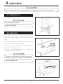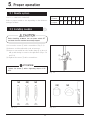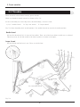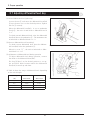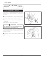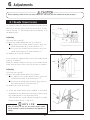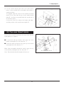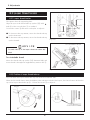
1
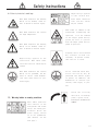
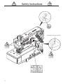
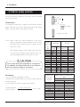
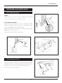
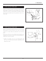
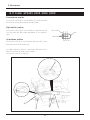
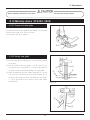
Instruction Manual
HIGH SPEED FLAT BED INTERLOCK STITCH MACHINE
VF2400 class
This instruction manual includes adjustments dif fered from VF2400.
Before using your machine mentioned above, please read both of
the instruction manuals and understand the contents well.
Af ter reading the instruction manual, please keep it in a location
where it is easily accessible to the operator.
CONTENTS
Safety instructions
ⅰ - iv
1. Name of each part
1
2. Installation
2
2.1 Semi-submerged type
2
2.2
Full-submerged type
5
2.3
Motor, pulley and belt
8
2.4
Hanging belt
9
2.5
Belt cover
9
2.6
Eye guard and finger guard
10
2.7
Thread guide plate
10
2.8
Tape stand (VF2403, 2404, 2503, 2504)
11
2.9
Tape holder (VF2404, 2504)
11
3. Sewing speed and rotating direction of pulley
12
4. Lubrication
13
4.1 Lubricating oil
13
4.2
Lubricating
13
4.3
Changing oil
14
4.4
Checking and replacing oil fileter
14
5. Proper operation
5.1 5.2
5.3
5.4
5.5
5.6
5.7
5.8
5.9
5.10
5.11
5.12
5.13
Needle system
Installing needles
Threading
Adjusting thread tension
Pressure of presser foot
Adjusting position of presser foot
Adjusting differential feed dog
Adjusting stitch length
HR device and SP device
Setting tape (VF2403, 2503, 2404, 2504)
Metering device (only for VF2404 and VF2504)
Adjusting hemming guide (VF2411)
Cleaning the machine
15
15
15
16
17
17
17
18
19
20
21
21
23
23
CONTENTS
6. Adjustments
24
6.1
Needle thread tension
24
6.2
Top cover thread tension
25
6.3
Looper thread tension
26
6.4
Removing presser foot and presser foot lift
27
6.5
Looper
28
6.6
Height of needle bar
29
6.7
Front-and-rear position of needle and looper
30
6.8
Needle and needle guard
31
6.9
Height of feed dog
32
6.10
Needle and spreader
32
6.11
Folder (VF2403, 2503, 2404, 2504)
34
6.12
Metering device (VF2404, 2504)
35
7. Specifications
37
Attention
◇This instruction manual is designed mainly for technicians , but it is advisable that also operators read
the instructions with
mark to use the machine properly.
◇The numbers in lower left corners of figures are figure numbers. We use them in texts as needed for
your reference.
Attention
The parts used for this product are subject to change without notice. If such a chang e is made , any part
of the contents and illustrations of this instruction manual may not conform to this product.
In preparing the instruction manual, we have made our best efforts for making it free of any error or
omission. If any error or omission should yet be found, it might not be rectified immediately.
Safety instructions
1. To ensure safe use
2.Installation and preparation
Always observe the following instructions to ensure the safe use of the industrial sewing machines and devices.
2-1 Instruction and training
1-1 Application and purpose
The sewing machine is designed to improve productivity in the sewing industry and must not be
used for other applications and purposes. Do not
use this sewing machine until it can be confirmed
that safety measures for the drive units have
been taken.
1-2 Before use
Read all instruction manuals thoroughly before
starting the use of this machine and follow
them.
Also, read the instruction manual for the installed
drive unit.
1-3 Working
environment
DO NOT WORK IN THE FOLLOWING ENVIRONMENTS:
- Place where atmosphere temperature and humidity give a bad influence the performance of
sewing machines.
- Outdoors and place where the sewing machines
are exposed to sunlight directly.
- Atmosphere containing dust, corrosive gases or
flammable gases.
- Place where voltage fluctuation exceeds ± 10 %
of the rated voltage.
- Place where power capacity necessary for the
used motor specifications cannot be secured.
- Place where strong electric or magnetic fields
are generated such as near large-output high
frequency transmitters or high frequency welding machines.
Operators and workers, who supervise, repair or
maintain the machine head and machine unit, are
required to have the adequate knowledge and operation skills to do the job safely. In order to
establish such necessary conditions, it needs
for the employer to plan and enforce the safety
education and training to those workers.
2-2 Sewing table and motor
(1) Prepare a machine table that has enough
strength to withstand the weight of the sewing head and any reaction while operating.
(2) Maintain a comfortable working environment
with considering the lighting and the arrangement of sewing machine so that the operators can work smoothly.
(3) When installing the control box and the related parts on the sewing machine, take care
about the posture of the worker.
(4) Install the drive unit correctly according
to the instruction manual.
2-3 Wiring
(1) Never connect the plug for power supply until assembly is finished.
(2) Fix the connectors securely to the sewing
machine head, motor, and electric apparatus.
(3) Do not apply excessive force to the connection cords.
(4) Connect the cords away from the driving
parts.
(5) Place the ground wire securely to the designated position on the machine head.
2-4 Before operation
1-4 Unpacking and transportation
(1) Unpack from the top.
(2) Never hold the parts near the needle or
threading parts when removing the sewing machine head from the buffer of box.
(3) When carrying the sewing machine head, have
an assistant.
(4) Pay attention not to get excessive impact or
shock when moving the sewing machine head
with a pushcart.
(1) Take care not to attach lubricant, silicone
oil, and grease on the eyes or skin.
Keep them away from children.
(2) Be sure to fill or drop lubrication oil before operating the sewing machine.
Use the Yamato SF oil as specified.
(3) Never put your hand under the needle or near
the moving parts of the machine when turning
on power supply switch.
i
Safety instructions
(4) When operating a new sewing machine, make
sure the rotating direction of pulley agrees
with the rotating-direction mark.
2-5 During operation
(1) Be sure to operate the sewing machine with
the safeguards such as belt cover, finger
guard, and eye guard.
(2) Never place the finger, hair or objects under the needle or close to the moving parts
while operating the sewing machine.
(3) Be sure to turn off the power supply switch
when threading or replacing the needles.
(4) Never place your hands close to the knives
when operating the sewing machine with the
trimming devices.
(5) Be sure to turn off the power supply switch
when terminating the sewing work or leaving
the sewing machine.
(6) If the sewing machine malfunctions, abnormal
sound or smell something unusual while operating, be sure to turn off the power supply
switch.
2-6 Removal
(1) Turn off the power supply switch if removed
or replaced any parts or during adjustment
of sewing machine.
(2) Do not pull the cord when removing the plug.
Be sure to hold the plug itself.
(3) A high voltage is applied inside the control
box. Turn off the power supply switch and
wait more than 5 minutes before opening the
cover.
3.Maintenance, inspection, and repair
(1) Follow the instruction manuals for maintenance, inspection, and repair.
(2) Entrust the maintenance, inspection, and repair to specially trained personnel.
(3) Be sure to turn off the power supply switch
and make sure the sewing machine and motor
completely stop before the maintenance, inspection, and repair. (If using a clutch motor, take care that the motor keeps turning
for a while even after turning off the power
ii
supply switch.)
(4) Be sure to remove the gasket too, when the
cover removed at the maintenance, inspection, and repair. If not removed, may be
injured at the edge of gasket.
(5) Do not modify the sewing machine by the
customer's judgment.
(6) Be sure to use original replacement parts
for repairs or maintenance.
4.Caution signs and alert pictorial markings
This instruction manual contains the following
caution signs and alert pictorial markings to
prevent you from injuring yourself or the sewing machine from being damaged.
Please follow the instructions.
4-1 Meanings of caution signs
WARNING indicates potentially hazardous situations which, if not heeded, could result in
death or serious injury to you and others.
Caution indicates hazardous situations which,
if not heeded, may result in minor or moderate
injury to you and others, or may result in machine damage.
NOTE is used to emphasize essential information.
Safety instructions
4-2 Alert pictorial markings
This mark indicates the warning
which, if not heeded, could result in death or Serious injury.
This mark indicates the caution
for high temperature.
This mark indicates the warning
which, if not heeded, could result in death or Serious injury.
High-voltage applies in the
control box. This label indicates that electric shock may be
caused.
This mark indicates the caution
which, if not grounded, the machine or device could malfunction and could result in personal injury.
5.Warning labels on sewing machines
This label indicates
that removal of the
safeguards and works
except for sewing performance while the
power supply switch
is on are prohibited.
(For details, see the
next page.)
High-voltage applies
in the control box.
This label indicates
that electric shock
may be caused.
This label is affixed on the
safeguards. Considering the
operation, it is not affixed
on the finger guard and eye
guard. Be sure to operate
with the finger guard and eye
guard in position.
Stepping motor and solenoid
may overheat if used continuously. To prevent a burn,
take care not to touch.
If not connected earth line,
static electricity may be
generated and inflict injury
on person. In addition, the
malfunction of electric system may cause injury to person.
Check the rotating
direction of machine
pulley agrees with '
ROTATING-DIRECTION
SYMBOL'.
iii
Safety instructions
Rotating direction symbol
iv
1. Name of each part
Thread guide plate
Handwheel
Seal plug(lubrication)
Oil sight window
SP device
Needle bar cover
Presser spring
regulator
Needle thread
take-up guard
Thread tension
spring cap
Feed regulating
pushbutton
Side cover
Looper thread
take-up cover
Oil sight gauge
Differential feed
graduation
Supporting plate for
looper thread take-up
Front cover
Finger guard
Fig. 1-1
Eye guard
Presser foot
VF2400
1
Section X -X (1/2)
Section Y -Y (1/2)
Fig. 2-1
VF2400
2
Refer to the instruction manual of the motor
for dimensions A, B, C, and D.
Operator
Table dimensions: 1200×595×40
center of pulley
2. Installation
2.1 semi-submerged type
2.1.1 Table cutting diagram
Standard
Section X - X
Section Y -Y
3
Refer to the instruction manual of the motor
for dimensions A, B, C, and D.
Operator
3- φ 9.5 installing hole of motor
Table dimensions: 1200×595×40
center of pulley
2. Installation
With UT device
Fig. 2-2
VF2400
2. Installation
2.1.2 Installation
sewing
machine
③
④
4㎜
③
①
②
③
②
Fig. 2-3
machine table
④
Install a machine correctly referring to Figs. 4 and 5.
Set the screws ② in the supporting board ① and cover the
screws ② with the rubber cushions ③ . Fix the the supporting board ① to the machine table and install a machine
securely on the rubber cushions ③ .
☆ The number of spacers ④
VF2400 class
Thickness of table
The number of spacers ④
40 ㎜
3 pcs. ×4= 12 pcs.
45 ㎜
2 pcs. ×4=8 pcs.
50 ㎜
1 pc. ×4=4 pcs.
Table 1
VF2400
4
①
Fig. 2-4
5
Section E - E
Section F - F
Section G - G
Section H - H
Operator
magnet
Note: 125 is reference dimension which differ by kindes of the motor.
“155” in the above figure is the distance to the bottom of the supporting board
so it must be set to the dimension where there will be no interference between
the motor control panel and the bottom and back end of the supporting board.
Supporting board
Table
magnet
magnet
3- φ 9.5 installing hole of motor
Refer to the instruction manual of the motor
for dimensions A, B, C, and D.
Note: (125)
Table dimensions: 1200×595×40
Magnet : Shown in the diagram are the
reference positions where the magnet
catches are to be installed.
Note: Position of the rear end
of supporting board
center of pulley
2. Installation
2.2 Full-submerged type
2.2.1 Table cutting diagram
Fig. 2-5
VF2400
2. Installation
thickness 20 ㎜
Auxiliary table
Fig. 2-6
thickness 35 ㎜
Supporting board
Fig. 2-7
VF2400
6
2. Installation
2.2.2 Installation
machine
table
③
②
①
Fig. 2-8
Install a machine correctly referring to Figs. 2-8 and 2-9.
Set the screws ② in the supporting board ① and cover the
screws ② with the rubber cushions ③ . Fix the the supporting board ① to the machine table and install a machine
securely on the rubber cushions ③ .
Fig. 2-9
①
VF2400
7
2. Installation
2.3 Motor, pulley and belt
See the instruction manual for the motor used and install
the motor properly.
58 ㎜
Clutch motor:
40°
To install the clutch motor, align the center of the machine
pulley with that of the motor pulley when the motor pulley
shifts to the left while toeing down the pedal.
5.5 ㎜
10 ㎜
M type of V-belt
Fig. 2-10
Note: Table 2 shows the outside diameter of the motor
pulley, sewing speed of the machine, and size of the
belt when using a clutch motor of 3-phase, 2-pole,
550 W (3/4 HP).
Outside
Use only those motor pulleys applicable to the machine. If
not applicable, the sewing machine will be over maximum
and it can cause the damage to the machine.
of machine
diameter of
80
85
90
95
100
105
110
115
120
125
130
135
140
145
Belt size
(sti/min)
pulley
(㎜)
The outside diameter on the table shows the nearest size to the calculated values based on the commercial available pulleys at intervals of 5 mm.
Sewing speed
50 Hz
4500
4800
5000
5250
5500
5750
6000
6200
6450
6700
6950
60 Hz
Table top
4500
4800
5100
5350
5650
5950
6200
6500
6800
M33
M33
M34
M34
M34
M35
M35
M35
M36
M36
M36
M37
M37
M38
Semisubmerged
M34
M34
M35
M35
M35
M36
M36
M36
M37
M37
M38
M38
M38
M39
Table 2
Servomotor:
Sewing speed
Use a servomotor with 500 W or more.
Calculate the outside diameter of a motor pulley from the
formula as below.
Or see Table 3 to select a proper motor pulley.
Outside diameter
=
of motor pulley
Usual sewing speed
× 58 + 5 mm
Servomoter speed
of machine
(sti/min)
4200
4500
4700
5000
5200
5500
5800
6000
6200
6500
7000
Table 3
VF2400
8
Outside diameter of motor pulley
(mm)
rpm of servomotor
3000 rpm
3600 rpm
86
73
92
78
96
81
102
86
106
89
111
94
117
98
121
102
125
105
131
110
140
118
2. Installation
2.4 Hanging belt
②
①
Before hanging belt, ALWAYS turn the power switch OFF
and check that the machine has already stopped.
10 - 20 ㎜
Use the M-type of V-belt.
③
(1) Hang the belt ① on the machine pulley ② , and then
on the motor pulley ③ while rotating the machine pulley.
(2) Adjust the belt tension so that the belt has a slack of
10 - 20 mm when its center is pushed with 10 N.
(3) Lock the motor with the adjusting bar ④ .
④
Fig. 2-11
2.5 Belt cover
Set the belt cover ⑤ . (Fig. 2-12)
⑤
Fig. 2-12
VF2400
9
2. Installation
2.6 Eye guard and finger guard
To ensure safe use, always install the eye guard ① and the
finger guard ② on the prescribed position when operating.
①
②
Fig. 2-13
2.7 Thread guide plate
(1) Put the screws ③ into the hole
of the thread
guide plate ④ and push it to the left.
(2) Fix the thread guide plate ④ with the screws ③ securely.
③
④
Fig. 2-14
VF2400
10
2. Installation
2.8 Tape stand (VF2403, 2404, 2503, 2504)
(1) Set the tape stand (Fig. 2-15).
(2) Fix the tape stand on the machine table with the wood
screws ① (Fig. 2-16).
(3) Adjust the direction of the tape guide bar ③ to feed a
tape into the folder ② smoothly.
①
①
②
③
Fig. 2-15
Fig. 2-16
2.9 Tape holder(VF2404, 2504)
Set the tape holder ④ on the screw ⑦ of the top cover
and the screw ⑧ of the head cover with the screws ⑤⑥
respectively.
④
⑥
⑤
⑦
⑧
Fig. 2-17
VF2400
11
3. Sewing speed and rotating direction of pulley
Table 4 shows maximum sewing speed and usual speed for
each model.
Run a new machine at speed about 15 - 20% lower than
maximum speed during the first 200 hours (for about one
month) so that a machine can offer a long service life in
good condition.
The rotating directions of the machine pulley ① and the
handwheel ② are clockwise as shown in the figure.
If rotated in reverse direction, oil cannot be supplied
properly. It can cause the damage to the machine.
Model
Max. speed
(sti/min)
Usual
speed
(sti/min)
VF2400, 2500 (with spreader)
6500
6000
VF2403, 2503 (with spreader)
6000
5500
VF2404, 2504 (with spreader)
5000
4500
VF2411 (without spreader)
7000
6500
VF2530 (with spreader)
5500
5000
Table 4
VF2400
12
②
①
Fig. 3-1
4. Lubrication
Before lubricating, ALWAYS turn the power switch OFF and check that the machine has already stopped.
4.1 Lubricating oil
Use YAMATO SF OIL No. 28.
Never add additives to the oil.
If added, it can cause the deterioration of the oil and the
damage to the machine.
①
4.2 Lubricating
When using a new machine, or a machine which has not
been run for a while, supply a few drops of oil to the needle
bar ① .
Fig. 4-1
③
②
Remove the seal plug ② indicated “OIL-IN” and supply oil
to the upper line of the oil sight gauge ④ .
Check that oil splashes from the nozzle inside the oil sight
window ③ while running a machine.
If oil does not splash from the nozzle, see “4.4 Checking
and replacing oil filter” on page 14.
Too much or insufficient oil can cause oil leakage and
machine trouble. Be sure to keep the oil level between
the lines. Also too much lubrication can cause the oil
scatter and material stain.
Fig. 4-2
④
Fig. 4-3
VF2400
13
4. Lubrication
Before lubricating, ALWAYS turn the power switch OFF and check that the machine has already stopped.
4.3 Changing oil
Period of changing:
When using a new machine, change the lubricating oil after
running a machine for 200 hours (for about one month).
After that, change the oil once or twice a year.
Procedure for changing:
(1)
(2)
(3)
(4)
(5)
Remove the belt cover. (page 9)
Remove V-belt from the motor pulley. (page 9)
Remove the machine from the machine table.
Set a container received the oil under the screw ① .
After removing screw ① , oil is drained.
①
Fig. 4-4
ATTENTION
Be careful not to soil the V-belt and the machine pulley
with the oil.
(6)
(7)
(8)
(9)
Reset the screw ① .
Change the oil. (See “4.2 lubricating” on page 13)
Reset the machine on the machine table.
Hang V-belt on the motor pulley and reset the belt
cover. (page 9)
4.4 Checking and replacing oil filter
◆ If the oil filter ② is clogged with dust, lubrication cannot be done properly.
◆ Remove the oil filter cap ③ and the oil filter ② to
check them every six months. If clogged or cracked,
clean or replace the oil filter.
◆ If oil is splashed from the nozzle insufficiently or includes many bubbles though the oil is sufficiently kept,
check or replace the oil filter.
③ O-ring
②
ADVICE
Carefully check and replace them without spilling oil
stagnant in the oil filter ② when loosening screw ④ .
VF2400
14
Fig. 4-5
5. Proper operation
5.1 Needle system
Use UY × 128GAS (UY128GAS).
Select a proper needle in size depending on the thickness
and type of fabric.
Japanese
standard
Metric
standard
9
10
11
12
13
14
65
70
75
80
85
90
Table 5
5.2 Installing needles
Before installing, ALWAYS turn the power switch OFF
and check that the machine has already stopped.
(1) Loosen the screws ① with a screwdriver. (Fig. 5-1)
(2) Remove an old needle with a pair of tweezers.
(3) Insert a new needle into the needle clamp ② as far as it
will go with facing its scarf to the right back. (Figs. 5-2
and 5-3)
(4) Tighten the screws ① with a screwdriver.
②
①
ATTENTION
Tighten the screws ① with a tightening torque of 0.6
N・m.
Fig. 5-1
NO
OK!
NO
OK!
Fig. 5-2
NO
Fig. 5-3
VF2400
15
5. Proper operation
5.3 Threading
When threaded, rethread after knotting preset threads.
When not threaded, thread correctly as shown in Fig. 5-4.
Incorrect threading can cause skip stitch, thread breakage, or uneven seam.
A, B, C: Needle thread
D: Top cover thread
E: Looper thread
Fig. 5-4 shows threading for 3-needle machine. Two needle threads are used for 2-needle machine.
Needle thread
Pull out the thread until it is in front of the needles. Then, cut off the knots before needle eye to rethread.
Thread correctly for the left needle in the inmost position as shown in the figure.
Looper thread
Pull the thread until the knot is out. Then, cut off the knot.
A B
C
for stretchable
thread
for stretchable thread
Fig. 5-4
VF2400
16
D E
5. Proper operation
5.4 Adjusting thread tension
Adjust the thread tension with the thread tension spring
caps ① depending on fabric type, thread type, seam width,
stitch length, and other sewing conditions.
● To tighten the thread tension, turn them clockwise.
● To loosen the thread tension, turn them counterclockwise.
①
Loosen
Tighten
Fig. 5-5
5.5 Pressure of presser foot
Loosen the lock nut ② and turn the presser spring regulator ③ to adjust the pressure.
Increase
Decrease
● To increase the pressure, turn it clockwise.
● To decrease the pressure, turn it counterclockwise.
③
Keep the pressure as low as possible for stable sewing performance.
②
Fig. 5-6
5.6 Adjusting position of presser foot
Before adjusting, ALWAYS turn the power switch OFF
and check that the machine has already stopped.
④
Adjust left-and-right position of the needle holes of the
presser foot.
Loosen the screw ④ . Move the front of the presser foot
right or left so that the needles drop in the centers of the
needle drops respectively.
Then, tighten the screw ④ securely.
Needles
Fig. 5-7
VF2400
17
5. Proper operation
5.7 Adjusting differential feed dog
(1) Normal differential feed (gathering)
Loosen the nut ① and move the differential lever(left)
② up or down to set it at the desired position. Tighten
the nut ① securely.
When the differential lever(left) is set at graduation
(Long) ③ , the ratio of main feed to differential feed is
1 : 1.
To obtain normal differential feed, raise the differential
lever(left) above the graduation ③ . The maximum ratio
of main feed to differential feed is 1 : 2.
(2) Reverse differential feed (stretching)
To obtain reverse differential feed, lower the differential lever(left) below the graduation ③ .
When it is set at “S” , the ratio of main feed to differential feed is 1 : 0.7.
①
②
③
Fig. 5-8
④
(3) Adjustment of differential feed during operation
To adjust differential feed during operation, connect
the chain to the differential lever(left).
Fix Stop ④ (2pcs.) at the desired position to set upper and lower limits between which the differential
lever(left) is moved up and down.
③
1:2
1:1.75
1:1.5
1:1.25
☆ Table 6 shows the range of differential ratio depending
on the stitch length.
Stitch length
Max. normal
Max. reverse
(㎜)
differential
differential
3.6
1:1.2
1:0.7
2.5
1:1.6
1:0.7
2.0
1:1.8
1:0.7
1.4
1:2.0
1:0.7
④
Fig. 5-9
Table 6
VF2400
18
5. Proper operation
Before operating, ALWAYS turn the power switch OFF and check that the machine has already stopped.
5.8 Adjusting stitch length
Stitch length can be adjustable from 1.4 to 3.6 mm.
Table 7 shows the number of stitches per inch (25.4 mm)
and 30 mm converted to the stitch length.
Stitch length
(㎜)
1.4
2.0
3.0
3.6
Number of stitch
(per 1 inch)
(25.4 ㎜)
18
13
8.5
7
①
Number of stitch
(per 30 ㎜)
21
15
10
8
Table 7
Each graduation on the machine pulley indicates the
length( ㎜ ) for one stitch.
After sewing, the actual stitch length has difference from
the length on graduation. It depends on the application, a
type and a thickness of fabric, or the differential ratio.
Fig. 5-10
(1) Rotate the pulley while the pushing pushbutton ① . At
the point as far as it will go, again push it securely.
(2) With keeping that, align desired graduation of the pulley with the mark ② on the machine.
(3) Release the pushbutton ① .
● To decrease stitch length, turn the pulley in the
direction “S” .
● To increase stitch length, turn the pulley in the
direction “L” .
②
Fig. 5-11
①
④
Check that push button is released completely and the
pulley rotates smoothly.
Pushbutton stop:
Use the pushbutton stop ④ to keep the stitch length to be
set.
Loosen the screws ③ to raise the pushbutton stop ④ .
After setting it under the pushbutton ① , tighten the
screws ③ securely.
③
Fig. 5-12
VF2400
19
5. Proper operation
5.9 HR device and SP device
③
Use SP device (needle thread oiling) and HR device (needle
point cooling) as standard equipment to prevent thread
breakage and skip stitch when running a machine at high
speed or using synthetic thread and/or synthetic fabric.
Use dimethyl silicon oil.
①
Note: Open the seal plug ① of HR container and the
lid ② of SP container to check the oil level.
Supply oil if needed.
Fig. 5-13
1. When not using SP or HR device, remove the felt ③ or
④ . If attached, It may occur irregular condition during
sewing.
2. If silicone oil is attached to the parts other than SP
and HR devices, it can cause the machine trouble. Be
sure to wipe it away.
②
④
Fig. 5-14
VF2400
20
5. Proper operation
Before operating, ALWAYS turn the power switch OFF and check that the machine has already stopped.
5.10 Setting tape (VF2403, 2503, 2404, 2504)
Set the tape role on the tape stand ① (Fig. 5-15).
Pull a tape forward through the folder ② and set it under
the presser foot ③ .
①
Unmatched folder width with tape width cannot be folded
properly.
③
②
Fig. 5-15
5.11 Metering device (only for VF2404 and VF2504)
5.11.1 Setting elastic tape
Set an elastic tape correctly (Fig. 5-16).
Pushing the roller lever ④ can make a clearance between
the rollers.
Set an elastic tape under the presser foot ⑤ and pull it
forward.
④
⑤
Fig. 5-16
VF2400
21
5. Proper operation
Before operating, ALWAYS turn the power switch OFF
and check that the machine has already stopped.
5.11.2 Feeding amount of elastic tape
Loosen the nut ① and adjust feeding amount while checking the pointer ② and the graduations of the clutch lever
③ as below.
● To increase feeding amount, turn the adjusting screw ④
clockwise and move the pointer ② in the direction “L”.
● To decrease feeding amount, turn the adjusting screw
④ counterclockwise and move the pointer ② in the direction “S” .
Tighten the nut ① securely after adjusting.
ATTENTION
②
①
③
S
④
L
Fig. 5-17
After tightening the nut ① , turn the adjusting screw ④
clockwise to tighten it securely without play.
If required feeding amount cannot be obtained by above
adjusting with the adjusting screw ④ , loosen the screw ⑤
and adjust it as below.
⑤
● To decrease feeding amount, turn the adjusting screw
⑥ clockwise.
● To increase feeding amount, turn the adjusting screw ⑥
counterclockwise.
⑥
Fig. 5-18
VF2400
22
5. Proper operation
Before operating, ALWAYS turn the power switch OFF and check that the machine has already stopped.
5.12 Adjusting hemming guide (VF2411)
Hemming guide(left):
(1) Loosen the screw ② of the hemming guide(left) ① .
(2) Adjust right-and-left position to align the fabric end to
the left needle.
(3) Tighten the screw ② securely.
Hemming guide(right):
(1) Loosen the screws ④ of the hemming guide(right) ③ .
(2) Adjust right-and-left position to align the fabric end
with hemming width.
(3) Tighten the screws ④ securely.
④
②
③
①
Fig. 5-19
5.13 Cleaning the machine
Clean waste thread and dust inside the machine at the end
of work a day.
Clean the grooves in the stitch plate, feed dog area, and
looper thread take-up area once a week.
Fig. 5-20
VF2400
23
6. Adjustments
Before adjusting, ALWAYS turn the power switch OFF and check that the machine has already stopped.
6.1 Needle thread tension
As standard, make the distance between the needle thread
take-up ① and the center of the left screw ② to 52 mm,
and set the part “a” horizontally when the needle bar is at
the highest point.
52 ㎜
a
T
L
Adjusting:
(1) Loosen the screws ② .
(2) Move the needle thread take-up ① to adjust it.
● To tighten the needle thread tension, move the
needle thread take-up ① in the direction “T” .
● To loosen the needle thread tension, move the
needle thread take-up ① in the direction “L” .
(3) Tighten the screws ② securely.
①
②
Fig. 6-1
③
If not enough for adjusting above, move the needle thread
eyelet ③ to adjust it.
Make the distance between the top of the needle thread
eyelet and the center of the screw ④ to 8 mm as standard.
②
④
T
8㎜
L
Adjusting:
(1) Loosen the screw ④ .
(2) Move the needle thread eyelet ③ to adjust it.
● To tighten the needle thread tension, move the
needle thread eyelet ③ in the direction “T” .
● To loosen the needle thread tension, move the needle thread eyelet ③ in the direction “L” .
(3) Tighten the screw ④ securely.
Fig. 6-2
☆ As the the needle thread loop is difficult to be formed
depending on the thread used, the looper cannot catch
the needle thread. It can cause skip stitch.
Then thread the needle thread through the needle
thread retainer dice ⑤ . (Fig. 6-3)
⑤
ADVICE
With UT device, do not use the needle thread retainer
dice ⑤ becasue it cannot form seams at the beginning of
sewing.
VF2400
24
Fig. 6-3
6. Adjustments
☆ Use the needle thread guide when the needle thread
forms a loop unstably with stretchable thread like a
synthetic thread.
As standard, align the center of the needle bar thread
eyelet ① eye even with the top of the needle thread
guide ② , and they are parallel when the needle bar is
at the lowest point.
Loosen the screw ③ to adjust the height and rightand-left position of the needle thread guide ② .
②
③
①
Fig. 6-4
6.2 Top cover thread tension
Loosen the screw ⑤ and move the top cover thread
eyelet(right) ④ to adjust it.
● To decrease take-up amount, move the top cover
thread eyelet(right) ④ in the direction “T” .
● To increase take-up amount, move the top cover thread
eylet(right) ④ in the direction “L” .
T
⑤
L
④
When using stretchable thread like woolly, move the top
cover thread eyelet(right) ④ in the direction “L” .
Note: Thread woolly thread through the lower eye.
for stretchable thread
Fig. 6-5
VF2400
25
6. Adjustments
6.3 Looper thread tension
③
①
6.3.1 Looper thread tension
Decrease
The figures show the supporting plate.
Align the eyes of the thread take-up eyelets ③④ with
mark ② of the cast-off plate ① as standard.
Loosen the screws ⑥ and move each eyelet to adjust it.
● To increase take-up amount, move the thread take-up
eyelets frontward.
● To decrease take-up amount, move the thread take-up
eyelets forward.
②
Decrease
Increase
⑥
Increase
④
Fig. 6-6
for stretchable thread
ADVICE
⑤
Too much take-up of the looper thread can cause skip
stitch.
③
For stretchable thread:
Move the thread take-up eyelets ③④ frontward fully and
never thread it through the supplementary tension disc ⑤ .
④
Fig. 6-7
6.3.2 Position of looper thread take-up
Fig. 6-8 shows the looper thread take-up seen from the needle bar side.
When the left needle lowers from the highest point and meets a half of the looper, the thread comes off from the
top of the looper thread take-up ⑥ . Loosen the screws ⑦ to adjust it.
thread
⑦
1/2
⑥
Fig. 6-8
Fig. 6-9
VF2400
26
6. Adjustments
6.4 Removing presser foot and presser foot lift
Removing presser foot
(1) Loosen the screws ② of the lifter lever stop ① , the
screws ④ of the collar ③ , and the screw ⑧ of the
presser foot ⑦ .
(2) Push down the lifter lever ⑤ to remove the presser foot
⑦.
①
⑤
Adjusting height of presser foot
(1) Push down the lifter lever ⑤ to make the height from
the top of the stitch plate to the bottom of the presser
foot to 7.0 mm (with spreader, needle distance 5.6 mm
on VF2500).
(2) Tighten the screws ② securely.
(3) With keeping that, make the clearance between the end
of the presser bar bushing ⑥ and the top of the collar
③ to 0.2 mm.
(4) Tighten the screws ④ securely.
After adjusting, push down the lifter lever ⑤ fully to check
the height of the presser foot.
②
Fig. 6-10
⑥
③
0.2 ㎜
④
⑦
⑧
stitch plate
Presser foot lift depends on the machine model or needle
distance.
See “7. Specifications” in detail.
7.0 ㎜
(8.0 ㎜ )
Fig. 6-11
VF2400
27
6. Adjustments
6.5 Looper
6.5.1 Installing angle and height of looper
Insert the looper ① into the looper holder ② fully and
tighten the screw ③ securely.
It makes the height and installing angle (3° ).
①
②
③
Fig. 6-12
6.5.2 Distance between looper and needle
The distance “M” between the looper tip and the center
of the right needle depends on the needle distance when
the needles are at the lowest points and the looper ① is at
the extreme right.
See Table 8 and loosen the screw ④ of the looper holder
to adjust the distance.
SUPPLEMENT
④
The distance between the center of the needle bar and
the looper ① tip is 6.0 mm even if the needle distance
changes.
Fig. 6-13
looper's distance
needle distance
gauge mark
3.2 ㎜
A
4.4 ㎜
4.0 ㎜
B
4.0 ㎜
4.8 ㎜
C
3.6 ㎜
5.6 ㎜
D
3.2 ㎜
6.4 ㎜
E
2.8 ㎜
“M”
Table 8
The timing gauge (No. 95220) makes it possible to adjust
the distance easily.
The gauge is an special order part. Place an order from our
agents or directly from us.
VF2400
28
6.0 ㎜
Fig. 6-14
6. Adjustments
6.5.3 Using timing gauge
針
C
D
A timing gauge has the marks (A, B, C, D, E) for each
needle distance (Table 8).
AE
B
Move the looper at the extreme right. Keep fitting the
right needle into the groove “V” corresponding needle
distance, and fit the looper tip to the gauge.
Then, tighten the screw ④ securely. (Fig. 6-13)
6.6 Height of needle bar
Fig. 6-15
Check points:
◇ Needles should be inserted fully into the needle holes of
the needle clamp and fixed securely.
◇ Looper should be inserted fully into the looper holder
and fixed securely.
Adjusting:
(1) Install the needle to the left hole in the needle clamp.
(2) Check the looper is inserted into the looper holder
fully.
(3) Turn the handwheel until the looper tip meets the center of the left needle.
(4) Loosen the screw ① of the needle bar bracket. Move
the needle bar up or down so that the looper tip passes
0.5 - 1.0 mm above the top of the needle eye.
(5) Tighten the screw ① securely. Check that the needles
drop in the centers of the needle holes of the stitch
plate respectively.
0.5 1.0 ㎜
Fig. 6-16
①
Fig. 6-17
Fig. 6-18
VF2400
29
6. Adjustments
6.7 Front-and-rear position of needle and looper
3-needle:
◇ When the looper tip ① meets the left needle ② , make
the clearance between them to 0.2 - 0.3 mm.
◇ When the looper tip ① meets the middle needle ③ ,
make the clearance between them to 0.05 - 0.15 mm.
◇ When the looper tip ① meets the right needle ④ , they
touch slightly by 0.2 mm.
Make the clearance between them to 0 - 0.05 mm to
push the needle guard(rear) to the right needle ④ .
◇ Loosen the screw ⑦ of the looper holder to adjust it.
①
0.2 0.3 ㎜
②
④
③
Fig. 6-19
2-needle:
◇ When the looper tip ① meets the left needle ⑤ , make
the clearance between them to 0.2 - 0.3 mm.
◇ When the looper tip ① meets the right needle ⑥ , they
touch slightly by 0.2 mm.
Make the clearance between them to 0 - 0.05 mm to
push the needle guard(rear) to the right needle ⑥ .
◇ Loosen the screw ⑦ to adjust it.
①
0.2 0.3 ㎜
⑤
⑥
Fig. 6-20
⑦
Fig. 6-21
VF2400
30
6. Adjustments
6.8 Needle and needle guard
6.8.1 Needle guard(rear)
Height:
Align the line “a” on the needle guard(rear) ① with the
center of the needle eye at the lowest point.
①
a
Front-and-rear position:
When the looper tip meets the center of the right needle,
make the clearance between them to 0 - 0.05 mm to push
the needle guard(rear) to the right needle.
Make the clearance between the left needle and the needle
guard(rear) to 0.05 - 0.1 mm.
Loosen the screws ②③ to adjust them.
Fig. 6-22
③
④
0 - 0.05 ㎜
②
0.05 - 0.1 ㎜
Fig. 6-24
Fig. 6-23
6.8.2 Needle guard(front)
Make the clearance between each needle and the needle
guard(front) ⑤ to 0 - 0.3 mm respectively when the looper
tip comes at the centers of the right and left needles.
Loosen the screw ⑥ to adjust it.
⑤
⑥
0 - 0.3 ㎜
Fig. 6-25
VF2400
31
6. Adjustments
6.9 Height of feed dog
When the feed dogs are at highest points, their tops are
parallel to the top of the stitch plate. Make the even height
of the differential feed dog ① and the main feed dog ② ,
and the height from the top of the stitch plate to their tops
to 1.0 - 1.2 mm.
6.10 Needle and spreader
②
1.0 - 1.2 ㎜
①
Fig. 6-26
6.10.1 Spreader
Make the clearance between the left needle and the hook
“a” to 0.5 - 0.8 mm when the spreader ③ moves from the
right to the left.
Make the clearance between the center of the left needle
and the hook “a” to 4.5 - 5.5 mm when the spreader
moves at extreme left.
Make the height from the top of the stitch palte to the
bottom of the spreader ③ to 9 - 11 mm.
Loosen the screw ④ of the spreader and the screw ⑤ of
the spreader holder ⑤ to adjust it.
a
0.5 - 0.8 ㎜
③
4.5 - 5.5 ㎜
HINT
Adjust the height of the spreader so that the top cover
thread passes behind the right needle and be caught by
the left needle within adjustable range based on the needle distance.
Fig. 6-27
③
⑤
9 - 11 ㎜
④
stitch plate
Fig. 6-29
Fig. 6-28
VF2400
32
6. Adjustments
6.10.2 Top cover thread guide
Make the clearance between the bottom of the top cover
thread guide ① and the top of the spreader ② to 0.5 mm.
Tighten the screws ③ securely where the thread is hooked
with the hook smoothly when the spreader ② comes at extreme right.
1.0 ㎜
③
①
0.5 ㎜
④
②
Fig. 6-30
6.10.3 Top cover thread eyelet
Make the clearance between the top of the top cover
thread guide ① and the bottom of the top cover thread
eyelet ④ to 1.0 mm when the needle bar is at the lowest
point.
Set the eye of the top cover thread eyelet along the extending line from the slot of the top cover thread guide ① .
Tighten the screw ⑤ securely.
①
④
* Adjust the spreader, the top cover thread guide, and
the top cover thread eyelet properly depending on the
thread to be used.
⑤
Fig. 6-31
VF2400
33
6. Adjustments
6.11 Folder (VF2403, 2503, 2404, 2504)
Front-and-rear position
Loosen the screws ② to set the folder ① near the presser
foot and the stitch plate without touchng them.
Right-and-left position
Loosen the screws ② to set the folder to align the left end
of a tape with the left needle depending on its specifications.
left needle
tape
fabric
Up-and-down position
Fig. 6-32
Loosen the screw ③ to set the fabric slide plate ④ 1/3 up
from the bottom of the folder exit.
Set right-and-left position of the fabric slide plate ④ to
align its end with the right end of a fabric.
Loosen the screw ⑤ to adjust it.
③
④
②
⑤
Fig. 6-33
VF2400
34
①
6. Adjustments
Before adjusting, ALWAYS turn the motor switch OFF and check that the motor has already stopped.
6.12 Metering device (VF2404, 2504)
6.12.1 Presser foot tape guide
Set the presser foot tape guide ① depending on the needle
distance and a part to be sewn on a tape.
Loosen the screw ② to adjust it.
②
①
Fig. 6-34
6.12.2 Setting tape guide
(1) Set the tape guide bar(long) ③ to a low position enough
for sewing.
(2) Set the inside of the tape guide, c. set ④ along “A” on
the presser foot tape guide ① . Set the tape guide ⑤
to guide a tape smoothly depending on a tape width.
(3) After positioning the tape guide bar(long) ③ , loosen
the screw ⑥ to position the tape guide stopper ⑦ . It
prevents the needle bar from touching the tape guide,
c. set ④ and makes the position of the tape guide
bar(long) ③ .
A
①
③
④
⑤
Fig. 6-35
⑦
⑥
③
Fig. 6-36
VF2400
35
6. Adjustments
Before adjusting, ALWAYS turn the motor switch OFF
and check that the motor has already stopped.
6.12.3 Pressure of elastic feed roller
③
②
To adjust the pressure of an elastic tape with tension
roller(small) ① , loosen the lock nut ② and turn the adjusting screw ③ .
● To increase the pressure, turn the adjusting screw ③
clockwise.
● To decrease the pressure, turn the adjusting screw ③
counterclockwise.
Keep the pressure as low as possible.
Too tight or loose pressure can cause uneven feeding of a
tape.
REFERENCE
①
Fig. 6-37
Too much change in tension of a tape from the bobbin
may occur uneven sewing finish size even if the tension
roller(large) feeds an elastic tape correctly.
An automatic elastic feeder“AEF-31”can feed an elastic tape smoothly and constant sewing finish can be obtained.
⑤
④
⑥
6.12.4 Maintenance of metering device
⑥
Replacement and repair:
Improper installation of the metering device can cause improper feeding of an elastic tape, skip stitch, needle breakage, bad sewing performance and others.
Carefully install the device as following points:
(1) Check that the roller shaft turns smoothly after setting it. Loosen the screws ④ and ⑤ and make interlining to adjust it.
(2) Set the tension roller(small) ① to turn smoothly like
a top. Improper turning of it can cause irregular
feeding of a tape.
(3) Set the tension link ⑥ and its shaft to turn smoothly.
(4) Set the tension spring pressure of the tension
roller(small) ① as low as possible so that it can follow the rotation.
Fig. 6-38
⑦
Lubrication:
Remove the screws ⑦ on the roller shaft to supply grease
on each part several times a year.
VF2400
36
Fig. 6-39
①
7. Specifications
Model
Description
VF2400, VF2500
VF2411
High speed flat bed 2 or 3-needle High speed flat bed 2 or 3-needle High speed flat bed 2 or 3-needle
interlock stitch machine
double chain stitch machine
Dimensions
500 (L)× 250 (W)× 430 (H)mm
Weight
41 kg
Stitch Type
ISO 406, 407, 602, 605
Application
Sewing Speed
VF2403, VF2503
interlock stitch machine
ISO 406
ISO 406, 407, 602, 605
Hemming operation
Attaching elastic lace
During intermittent operation
During intermittent operation
During intermittent operation
Max. 6500 sti/min
Max. 7000 sti/min
Max. 6000 sti/min
Plain seam and covering for
knitted fabric
1.4 - 3.6 mm
Stitch Length
The number of stitches 7 - 18 stitches per inch (25.4 mm)
8 - 21 stitches per 30 mm
Needle system
UY X 128GAS of Shumetz or Organ #65 - #90
Needle
3-needle: 4.8, 5.6, 6.0, 6.4 mm
Distance
2-nnedle: 3.2, 4.0, 4.8, 6.4 mm
Needle Stroke
31 mm
2-nnedle: 4.0, 4.8, 6.4 mm
6.0 mm (needle distance: 6.4 mm)
Presser Foot
- 8.0 mm (3.2 mm):
Lift
with spreader:7.0 mm
Regulation
Differential
Ratio
2-nnedle: 3.2, 4.0, 4.8, 6.4 mm
5.0 mm (needle distance: 6.4 mm)
without spreader: 8.0 mm
- 7.0 mm (3.2 mm):
without spreader: 7.0 mm
without spreader: 8.0 mm
Feed
3-needle: 4.8, 5.6, 6.4 mm
Push button system
1:0.7 - 1:2
Differential
Feed
External lever even during operation
Regulation
Lubrication
Lubrication automatically by pump
Lubricating Oil
YAMATO SF OIL #28
Capacity of Oil
Reservoir
Installation
Compliance
with Regulator
1100 ml
Full-submerged type and semi-submerged type
CE Marking
LpA=83.3 dB(6000sti/min)
Noise level
LpA=81.2 dB(6500sti/min)
LpA=83.3 dB(6000sti/min)
according to ISO 10821-C6.2-ISO according to ISO 10821-C6.2-ISO according to ISO 10821-C6.2-ISO
11204 GR2
11204 GR2
11204 GR2
VF2400
37
7. Specifications
Model
Description
VF2404, VF2504
VF2530
High speed flat bed 2 or 3-needle interlock stitch High speed flat bed 3-needle interlock stitch
machine with metering device (clutch)
machine
Dimensions
500 (L)× 250 (W)× 430 (H)mm
Weight
42.5 kg
Stitch Type
ISO 406, 407, 602, 605
Application
Attaching tape
Plain seam and covering
During intermittent operation
During intermittent operation
Max. 5000 sti/min
Max. 5500 sti/min
Sewing Speed
41 kg
1.4 - 3.6 mm
Stitch Length
The number of stitches 7 - 18 stitches per inch (25.4 mm)
Needle system
Needle Distance
Needle Stroke
8 - 21 stitches per 30 mm
UY X 128GAS of Shumetz or Organ #65 - #90
3-needle: 5.6 mm
3-needle: 5.6, 6.4 mm
2-nnedle: 3.2, 4.0, 4.8, 6.4 mm
31 mm
5.0 mm (needle distance: 6.4 mm) -
Presser Foot Lift
7.0 mm (3.2 mm):
with spreader: 8.0 mm
without spreader: 7.0 mm
Feed Regulation
Push button system
Differential Ratio
1:0.7 - 1:2
Differential Feed
Regulation
External lever even during operation
Lubrication
Lubrication automatically by pump
Lubricating Oil
YAMATO SF OIL #28
Capacity of Oil
Reservoir
Installation
Compliance with
Regulator
Noise level
1100 ml
Full-submerged type and semi-submerged type
CE Marking
LpA=82.3 dB(4500sti/min) according to ISO
LpA=83.3 dB(5500sti/min) according to ISO
10821-C6.2-ISO 11204 GR2
10821-C6.2-ISO 11204 GR2
VF2400
38
4-4-12, NISHI T ENM A , K I T A - K U , O S A K A , J A P A N
T E L:81- 6 - 6 3 6 4 - 5 6 21 F A X:81- 6 - 6 3 6 5 - 718 5
〒530-0047 大 阪 市 北 区 西 天 満 4 丁 目 4 番 12 号
TEL( 0 6) 6 36 4-56 21( 代 )FAX( 0 6) 6 36 5- 718 5
P/N 9720028( I )
No.7 Edited in 2010.2
(VF2400)
Printed in Japan 2010.2.3H U