1
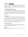
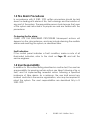
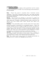
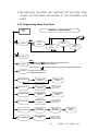
RE –102 RE - 104 Fire Alarm Control Panel Installation, Commissioning & Operating Manual 1 P/N RE - 102 / 104 Rev. No. 0 2 P/N RE - 102 / 104 Rev. No. 0 NOTES: 3 P/N RE - 102 / 104 Rev. No. 0 Table of Contents CHAPTER 1: Introduction …………........…….....................4 1.1: System Design & Planning..............................................4 1.2: General .………...............................................................4 1.3: Fire Alarm Procedure ….................................................5 1.4: User Responsibility.........................................................5 1.5: Routine test............….....................................…………..6 CHAPTER 2: Product Description .....................................7 2.1: Product Features ...........................................................7 2.2: Specifications ...........................................................…..8 2.3: Controls and Indicators .................................................9 2.3.1: LED Indication...........................................…………...9 2.3.2: Controls……………………….…..….…………………..10 2.4: Mechanical Construction…….……………………………10 CHAPTER 3: Installation ..............................……..........….11 3.1: Installation Precaution……….……………………………11 3.2: Mounting Details ...................................................….…13 3.3: Input Circuits.............................................................….14 3.4: Output Circuits .........................................................….15 CHAPTER 4: Operating Instructions...….............….….....16 4.1: Switch Functions …………………….............................16 4.2: Status LED....................................….........................…17 4.3: Operation..................................................................….18 4.3.1: Zone Fault Response ................................................18 4.3.2: Zone Fault Restoral …...............................................18 4.3.3: Zone Fire Response ...........................................….. 18 4.3.4: Zone Fire Restoral …...........................................…. 18 4.3.5: programming Menu Flow Chart ….…………..............19 CHAPTER 5: Servicing……………………………..…………20 5.1: Walk test mode… …………………….............................20 5.2: Installation/Replacement of PCB................................…21 5.3: Test……....................................................................….21 5.4: Lamp Test…..............................................................….21 CHAPTER 6: Power Calculation….….………………………22 CHAPTER 7: Trouble Shooting……….……………………..23 CHAPTER 8: Terminal Detail….…..………………….………24 4 P/N RE - 102 / 104 Rev. No. 0 Chapter 1: Introduction This manual is intended as a complete guide to the RE - 102 / 104 model Conventional Fire Control Panel. User operating Instructions are provided in the first part of this manual. This is followed with sections describing installation and commissioning procedures and full technical details are provided. 1.1 System Design and Planning It is assumed that the system, of this control panel is a part, which has been designed by a competent fire alarm system designer in accordance with the requirements of IS 2189: 1999 and any other local codes of practice that are applicable. The design drawings should clearly show the positions of the field devices and the control equipment. 1.2 General The panel is self-contained with integral power supply and space provision for two sealed lead-acid standby batteries and comply with the requirements of IS 2189: 1999. The panel functions are microprocessor controlled and test and isolate functions are included. Provision is made for a repeater function of panel status output. The panel can accept, per zone, automatic detectors with a total maximum loading of 2.4mA quiescent current rating (refer to chapter 2.2), and an unlimited number of manual call points. End of Line (EOL) devices The panels can continue to monitor manual call points with detectors removed, providing the detectors are fitted with a Schottky diode and an a EOL device is used. Installation The panel is easy to install and operate. The panel fascia is retained by tamper-proof screws. 5 P/N RE - 102 / 104 Rev. No. 0 1.3 Fire Alarm Procedures In accordance with IS 2189: 1999, written procedures should be laid down for dealing with alarms of fire, fault warnings, and the isolation of any part of the system. The responsible person should ensure that users of the system are instructed in its proper use and are familiar with the procedures. On hearing the fire alarm: CARRY OUT THE PRESCRIBED PROCEDURE Subsequent actions will depend on the circumstances, and may include silencing the audible alarms and resetting the system, as described later. Fault Indication: If the control panel indicates a Fault condition, make a note of all illuminated indicators, refer to the chart on Page 23, and call the service engineer. 1.4 User Responsibility In addition to the routine testing described on routine test, the user has a responsibility for ensuring certain actions are taken following a fire or fault, and for implementing remedial action following a specified incidence of false alarms. As a minimum, the user shall record any incident and inform the service organization, who may be required to retest the system. The user's responsibilities are described fully in IS 2189: 1999. 6 P/N RE - 102 / 104 Rev. No. 0 1.5 Routine Testing In order to ensure that the system is fully operational, and to comply with the requirements of IS 2189: 1999, the following routine attention is recommended: Daily - Check the panel to ascertain that it indicates normal operation. If any fault is indicated check that it has been recorded and that the appropriate actions have been taken, e.g. informing the maintaining company. Weekly - Test at least one detector or call point to confirm the operation of the panel and the audible alarms. Test a different zone each week and, if possible, a different device. Keep a record of the device and zone tested each week. Record and report any malfunction. Quarterly - The responsible person should ensure that every three months the system is checked by a competent person. Check the standby batteries and the charger voltage Test at least one device in each zone to check the panel functions. Check the operation of the audible alarms and any link to a remote manned centre, Central Station, etc. Carry out a visual inspection of the installation to check for alterations or obstructions and issue a certificate of testing. Annually - The responsible person should ensure that, in addition to the quarterly checks, each device on the system is tested and that a visual inspection is made of the cable fittings and equipment. Note: The control panel case should be cleaned periodically by wiping with a soft, damp cloth. Do not use any solvents. 7 P/N RE - 102 / 104 Rev. No. 0 Chapter 2: Product Description The RE - 102 / 104 is a 2 / 4 zone microprocessor based conventional Fire Alarm Control Panel. The Panel accepts water flow devices, conventional input devices like 2 wire smoke detectors, pull stations and other normally open contact devices. The Outputs include Notification Appliance Circuits (sounders), Three Form – C relays 2 for alarm, 1 for fault and RS485 port to interface with remote annunciator (Optional). It supervises all wiring, AC voltage and Battery level. 2.1 Product Features ¾ ¾ ¾ ¾ ¾ ¾ ¾ ¾ ¾ ¾ ¾ ¾ ¾ ¾ ¾ ¾ ¾ Rugged CRCA sheet with powder coated finish. Operates on 220v, 50Hz AC supply. Standby battery back up with built in charging. Error free Fire / Fault status in unambiguous colored LED indication. Switch Mode Power Supply. 16 X 2 LCD Display. Tactile key pad for easy operation. Main, Standby status indication. Low Battery visual warning with audible tone. Zone wise one man walk test facility. RS 485 communication port for Repeater / network. (Optional). Relay output for actuators. Lamp Test facility. Zone Isolation facility with loop voltage cut off. Programmable Keypad lock. Programmable Auto Silence. Compatible to all types of conventional detectors. 8 P/N RE - 102 / 104 Rev. No. 0 2.2 Specification AC Power 220 VAC, 50 Hz. +10% - 15% Battery (Lead Acid only) Charging: Constant Voltage – 27.6v @ 0.5A(Max) Charging Capacity: 7 Amp Hour Battery Max. System Quiescent Current: 60mA Initiating Device Circuits (Zone Circuit) All zones are Class B wiring Normal Operating Voltage: Nominal 24 VDC Alarm Current: 15 – 35mA threshold Short Circuit Current: 42mA Maximum Loop resistance: 50 ohms Maximum End-Of-Line Resistor: 4.7K, 1/4watt Standby Current: 6.8mA (2.4mA for Detectors) Notification Appliance Circuits (Sounder Circuit) Class – B wiring Operating Nominal Voltage: 24 VDC Hooter (NACs) output: 1A End-Of-Line Resistor: 4.7K, 1/4watt Three Form – C Relays Relay Contact Rating: 2Amps @ 30 VDC, 2Amps @ 30VAC (Fire – 2 No’s, Fault – 1 No.). 9 P/N RE - 102 / 104 Rev. No. 0 2.3 Controls and Indication 2.3.1 LED Indication System On – Green A.C Power On – Green Standby On – Green Hooter Fault – Yellow Silenced – Yellow Zone Fire – Red Zone Fault – Yellow Zone Isolate / Walktest – Yellow Local Buzzer A piezo buzzer provides separate and distinct sounds for alarm and trouble conditions: Alarm – steady Fault – pulse 0.5sec ON and 0.5sec OFF 2.3.2 Controls SILENCE Key: During fire/fault condition, silence key is used to silence the external Sounders (NAC) and the internal buzzer tone. 10 P/N RE - 102 / 104 Rev. No. 0 RESET Key: This key is pressed to reset the entire system and While in reset condition, all detector loop voltages are cut off up to 3 seconds for Detectors and MCP’s, Then voltages are put on to the loop. CURSOR KEYS: The cursor keys (Right / Left arrows) are used to move the menu list and menu options. ENTER Key: This key is used to enter into menu edit mode and accept the changes of edited menu. This key also used for lamp test in system normal condition. MENU Key: This key is used to enter into the Main menu in the LCD. 2.4 Mechanical Construction The enclosure of the Panel is constructed by CRCA sheet with powder coated finish and it’s designed to afford the degree of protection as per IP-54. The ∅19mm knock outs are given for cable entry at the top of the cabinet. The panel also has a built in battery provision to accommodate 2 Nos. of 12v, 7Ah batteries. The front side of the panel consists of the following, a. Tactile switches. b. LED indications 11 P/N RE - 102 / 104 Rev. No. 0 Chapter 3: 3.1 Installation Installation Precaution Installation Precautions WARNING - Several different sources of power can be connected to the fire alarm control panel. Disconnect all sources of power before servicing. Control unit and associated equipment may be damaged by removing and/or inserting cards, modules, or interconnecting cables while the unit is energized. Do not attempt to install, service, or operate this unit until this manual is read and understood. CAUTION - System Reacceptance Test after Software Changes. To ensure proper system operation, this product must be tested in accordance with NFPA 72 after any programming operation or change in sitespecific software. Reacceptance testing is required after any change, addition or deletion of system components, or after any modification, repair or adjustment to system hardware or wiring. All components, circuits, system operations, or software functions known to be affected by a change must be 100% tested. In addition, to ensure that other operations are not inadvertently affected, at least 10% of initiating devices that are not directly affected by the change, up to a maximum of 50 devices, must also be tested and proper system operation verified. This system meets NFPA requirements for indoor dry operation at 0-49° C/32-120° F and at a relative humidity of 93 ±2% RH (non-condensing) at 32 ±2° C/90 ±3° F. However, the useful life of the system's standby batteries and the electronic components may be adversely affected by extreme temperature ranges and humidity. Therefore, it is recommended that this system and all peripherals be installed in an environment with a nominal room temperature of 050° C/32-120° F. 12 P/N RE - 102 / 104 Rev. No. 0 Verify that wire sizes are adequate for all initiating and Indicating device loops. Most devices cannot tolerate more than a 10% I.R. drop from the specified device voltage. Adherence to the following will aid in problem-free installation with long-term reliability: Like all solid-state electronic devices, this system may operate erratically or can be damaged when subjected to lightning-induced transients. Although no system is completely immune from lightning transients and interferences, proper grounding will reduce susceptibility. Overhead or outside aerial wiring is not recommended, due to an increased susceptibility to nearby lightning strikes. Consult with the Technical Services Department if any problems are anticipated or encountered. Disconnect AC power and batteries prior to removing or inserting circuit boards. Failure to do so can damage circuits. Remove all electronic assemblies prior to any drilling, filing, reaming, or punching of the enclosure. When possible, make all cable entries from the sides or rear. Before making modifications, verify that they will not interfere with battery, transformer, and printed circuit board location. Do not tighten screw terminals more than 9 in-lbs. Over-tightening may damage threads, resulting in reduced terminal contact pressure and difficulty with screw terminal removal. Though designed to last many years, system components can fail at any time. This system contains static-sensitive components. Always ground yourself with a proper wrist strap before handling any circuits so that static charges are removed from the body. Use static-suppressive packaging to protect electronic assemblies removed from the unit. Follow the instructions in the installation, operating, and programming manuals. These instructions must be followed to avoid damage to the control panel and associated equipment. FACP operation and reliability depend upon proper installation by authorized personnel. 13 P/N RE - 102 / 104 Rev. No. 0 3.2 Mounting Details 30 mm 35 mm 185 mm 30 mm 290 mm 175 mm Place the panel in its mounting position and fix the panel to the wall using the slots of the four screws. Ensure the enclosure and the inner parts of the panel are given sufficient protection during installation. All external cables are to be entered via the ∅19mm preformed knockouts located at the top of the panel. When the installation of all the cables has been completed, clean the interior of the enclosure ensuring all masonry debris and drilling swords are removed. 14 P/N RE - 102 / 104 Rev. No. 0 3.3 Input Circuits The control panel has 2 / 4 zone input circuits depending on the variant. The maximum loop resistance limit for each input circuit is 50 ohms. All field wiring of each zone is supervised for opens and ground faults. Both conditions are visually and audibly (toggle tone) annunciated. Each zone is a Class B Initiating Device Circuit (IDC – Zones) designed to accept any normally open contact devices and conventional 2-wire, 24 volt smoke detectors. It is allowable to mix an assortment of device types (i.e. smoke detectors, heat detectors, pull stations, etc.) on any zone. Zone Circuit – Class B 15 P/N RE - 102 / 104 Rev. No. 0 3.4 Output Circuits Sounder Circuits: The RE - 102 / 104 provides Notification Appliance Circuits standard as Class B. The total load capacity of this circuit is capacity of this O/P is 1Amps. Sounder Circuit – Class B Note: If the non polarized devices are used, connect the device as mentioned in page 23. Standard Relay The control panel provides three Form-C relays (2 for Fire & 1 fro Fault) rated for 2.0 amps @ 30 VDC and 2.0 amps @ 30 VAC. Relay connections are power-limited. 16 P/N RE - 102 / 104 Rev. No. 0 Chapter 4: Operating Instruction 4.1 Switch Functions SILENCE Key: This key is used in Fire / Fault Condition. To acknowledge the external sounder / internal buzzer press this key. During fire condition, after silencing the silence LED glows to indicate that external Sounders (NAC) are silenced. RESET Key: This key is used in only Fire Condition. The panel is reset by pressing this key followed by password if enabled. During reset condition, all the detector input voltages are cut off up to 3 seconds for Detectors and MCP’s, Then voltages are put on to the loop. ENTER Key: This key is used to check the all LED’s in panel is in good condition with continuous buzzer tone in normal operating condition. The same key is used to accept the selection of menu and changes done in the menu. CURSOR KEYS: The cursor keys (Right / Left arrows) are used to move the menu list and menu options. 17 P/N RE - 102 / 104 Rev. No. 0 MENU Key: The MENU key is used to enter into the programming mode for changing the zone status and other settings. The various steps involved in this menu are shown as flow chart 4.3.5. After entering into the menu, screen will be as below, 1. Zone 1 Enable 4.2 Status LED: Normal: In the Normal Condition, SYSTEM ON, AC POWER ON, green LED will be illuminated. There should be no other amber / red LED visual indication or audible tone. A.C POWER ON: This LED indicates the presence of main supply. Whenever the Main Supply (220v A.C) is present this LED will glow. Whenever the Main Supply (220v A.C) fails / fuse blown, the AC Power on LED will OFF and it also indicated by fault Buzzer tone. BATTERY ON: This LED indicates the presence of standby power supply. Whenever the Main Supply (220v A.C) fails, the panel supply is switched to standby power supply with BATTERY ON indication. Whenever the backup battery fails / fuse blown, the battery fail is indicated by LCD with fault Buzzer tone. Note: Whenever the backup battery voltage goes below the 21v, the battery on LED will be blinking with toggle Buzzer tone. HOOTER FAULT: Whenever there is any fault in Notification Appliances Circuits like Hooter (Sounder) loop open / short, it will be identified by COMMON HOOTER FAULT LED. SILENCED: Whenever the External Sounders are silence in presence of actual fire. After silencing this LED glows with toggle buzzer tone. 18 P/N RE - 102 / 104 Rev. No. 0 4.3 Operation 4.3.1 ZONE FAULT RESPONSE: When faults like Open/ Short occurred in the loop, the corresponding ZONE FAULT LED would identify it. Note: During the above fault conditions, apart from the specific fault identification LED, common fault relay and Local buzzer with intermittent tone will be activated. During this time, if ‘SILENCE.’ is activated, intermittent tone will be silenced. 4.3.2 ZONE FAULT RESTORAL: When the faults condition of the FAP is restored, then the corresponding fault LED goes off and also common fault relay and intermittent buzzer tone is deactivated. 4.3.3 ZONE FIRE RESPONSE: When the control panel detects Fire via the Detector / MCP, the corresponding ZONE FIRE red LED will be illuminated. At the same time hooter, potential free contact (Fire Relay) and local buzzer (continuous tone) will be activated. The External hooter (NAC / Sounder) and buzzer will be silenced by using the Silence Key and silenced LED indicates it. Always the recent fired zone FIRE LED will blink continuously, rest of the fired zone FIRE LED’s will glow constantly till it goes to RESET. The FIRE LED indication will remain ON condition till the panel is RESET. 4.3.4 ZONE FIRE RESTORAL: The control panel returns to normal after all alarms have been cleared and a system reset key has been pressed followed by the password if enabled. The control panel will perform the following upon restoral of all active alarms, The Zone Fire LED, Hooters, buzzer and fire relay are turn off. Note: 1. The Fire relay will be in ON condition till the fire and fault LED’s go OFF. 19 P/N RE - 102 / 104 Rev. No. 0 2. By silencing, sounders are switched off and Fire relay output for actuators will remains in ON Condition until reset. 4.3.5 Programming Menu Flow Chart: MENU KEY - FLOW DIAGRAM Menu Key 1. Zone 1 Zo ne Test 1. Zone 1 Enabled 1. Zone 1 1. Zone 1 Walk Test 1. Zone 1 Disabled De fa ul t 2. Zone 2 Note: 3. Zone 3 1. Use Cursor key ( ) to move the menu list previous or next and to interchange the status of the menu. 2. Use Enter Key ( 4. Zone 4 ) to select the menu list and conform the change of the status. 3. Menu 2,3,4 are same as 1. 4. default Password is '123'. 5. Auto KeyLo ck 5. Auto KeyLock Ena bled 6. KeyLock Time 6. KeyLock Time 060 (secs) 7. Auto Silence 7. Auto Silence Enabl ed 8. Sile nce Time 8. S ilence Tim e 060 (secs) 9. Chge Passwo rd Enter Old P assword?X XX 10. Net Address 10. Net Address <01> 5. Auto Ke yLock Disabled Use Cursor Key to Increa se / D ecrea se the ti me del a y 7. Auto Silence Disabled Use Cursor Key to Incr ea se / Decre a se the t i me del a y Ente r New Pa ssword?X XX Password Changed Use Cursor Key to Increa se / D ecrea se the Network Address 20 P/N RE - 102 / 104 Rev. No. 0 4.3.5.1. Zone 1 From this menu, the zone 1 loop can configured as enable, disable, Zone test and Walk test. The default option is ‘Enable’. To change the options press ‘Enter’ key, then change the options by using the left/ right cursor keys. The Screen will be as shown below. 1. Zone 1 <Enabled> Enable Mode: In this mode the zone will be in normal condition to detect the fire with detectors and manual call point (normally open devices). Disable Mode: In this mode the zone is disabled with loop voltage cut off. Note: Avoid disabling any zone unless it is really essential. Zone Test Mode: In this mode the zone is Tested for Fire, Open, Short and Isolate automatically without disturbing the normal operations. Walk test Mode: In this mode the selected zone is used to check all the loop devices manually one by one. The signal from the Initiating device will cause the panel in the alarm mode. The panel automatically get silenced and reset after a specific period without activating the fire relay. In this mode reset is done for only that particular zone. When entering into this mode the Fire relay output disablement is activated automatically and it will go back to previous status while we are coming out from this mode. For other zones that are not in walk test mode, if they sense any fire, then the panel will go to normal alarm mode and walk test zone changed to alarm mode automatically. 21 P/N RE - 102 / 104 Rev. No. 0 This feature helps to perform the testing of devices by a single person. In this mode if the zone detects any fire then after 4 seconds the panel will get automatically silenced. After 2 seconds of silence, the zone will go to reset. Note1: a. If there is no more testing, please ensure that the zone is brought back to the normal Condition. b. To bring back the zone loop to normal condition, same procedure is followed as for the test. c. If the zone is kept in Walk test mode for 10 minutes with out any test the panel comes out of the walk test mode automatically. d. During test condition that the other zones that are not in test mode fire will consider as actual fire. 4.3.5.2. Zone 2 From this menu, the zone 2 loop can configured as enable, disable, Zone test and Walk test. The default option is ‘Enable’. To change the options press ‘Enter’ key, then change the options by using the left/ right cursor keys. The Screen will be as shown below. 2. Zone 2 <Enabled> 4.3.5.3. Zone 3 From this menu, the zone 3 loop can configured as enable, disable, Zone test and Walk test. The default option is ‘Enable’. To change the options press ‘Enter’ key, then change the options by using the left/ right cursor keys. The Screen will be as shown below. 3. Zone 3 <Enabled> 22 P/N RE - 102 / 104 Rev. No. 0 4.3.5.4. Zone 4 From this menu, the zone 4 loop can configured as enable, disable, Zone test and Walk test. The default option is ‘Enable’. To change the options press ‘Enter’ key, then change the options by using the left/ right cursor keys. The Screen will be as shown below. 4. Zone 4 <Enabled> 4.3.5.5. Auto Key Lock From this menu, the Auto key lock can enabled or disabled. By pressing the ‘Enter’ key from this menu the option can be changed by using the Left / Right keys. The default factory setting option is ‘disabled’. If the key lock is enabled, the Auto lock time is enabled automatically and after the set time delay key pad will be locked. 4.3.5.6. Auto Lock Time The Auto key lock time will be enabled only when the Auto Key lock is ‘Enabled’. If the Auto Key Lock is in Enabled condition, then by pressing the ‘Enter’ key from this menu the key lock time can be changed by using the Left / Right keys. The default factory setting option is ‘disabled’ and default set time is 60 Seconds. 4.3.5.7. Auto Silence From this menu, the Auto Silence can enabled or disabled. By pressing the ‘Enter’ key from this menu the option can be changed by using the Left / Right keys. The default factory setting option is ‘disabled’. If the Auto Silence is enabled, the Silence time is enabled automatically and after the set time delay Sounders will be silenced automatically. 23 P/N RE - 102 / 104 Rev. No. 0 4.3.5.8. Silence Time The Silence time will be enabled only when the Auto silence is ‘Enabled’. If the Auto Silence is in Enabled condition, then by pressing the ‘Enter’ key from this menu the key lock time can be changed by using the Left / Right keys. The default factory setting option is ‘disabled’ and default set time is 60 Seconds. 4.3.5.9. Change Password From this menu, the password used for key panel enable can be changed. The default factory setting password is ‘123’. The password should be three digits. Enter Old Password? Enter New Password? Password Updated 4.3.5.10. Net Address From this menu, the network address used for network panel can be changed. The default factory Net work address is ‘1’. The network address can changed by pressing ‘Enter’ key from this menu, it enters into change mode then the address is changed by using the Left / Right keys. 24 P/N RE - 102 / 104 Rev. No. 0 Chapter 5: Servicing 5.1 Walk Test Mode: The RE - 102 / 104 provides the capability to perform a walktest of the system without triggering the Fire Relay. Walk test Mode allows for testing of all the zones. For a walktest, the initiating device activated on a zone will cause the Notification Appliance Circuits (Sounder/Hooter) to turn on for three seconds. Any smoke detectors that are activated will be reset automatically after 6 seconds. Placing the control panel into Walktest Mode will be possible only if the system has no active alarms. While the selected zone work as walk test and other zone will works normally. After entering into the walktest mode, the fire relay contact disablement is activated automatically and it will go back to previous status while we are coming out from this mode. This feature helps to perform the testing of devices by a single person. In this mode if the panel detects any fire then after 3 seconds the panel will get automatically silenced. After 6 seconds of silence, the panel will go to reset. This reset is done for only that particular zone. Once in Walktest Mode, the control panel will immediately: • • • • • Disable the fire relay. Display all alarm conditions as they occur. Display all zone troubles as they occur. Display all system troubles as they occur. If fire is created, turns on the Notification Appliance Circuits for 3 seconds for alarm on a zone. Note: a. If the other zone (Normal Zone) get triggered by actual fire, the FAP treat as real fire and activates NACs and actuators. b. The maintenance person should enter into the walktest mode in normal condition of the panel. c. If there is no more testing, ensure that the zone is brought back to the normal Condition. d. During in this mode, the Potential free Relay will not be activated while in fire condition. e. If there is no more testing for 10 minutes, the panel return back to normal mode automatically. 25 P/N RE - 102 / 104 Rev. No. 0 5.2 Installation/Replacement of PCB: Remove the screws of PCB, which has to be changed and remove the PCB from the mounting position and place the new PCB in that same position with the screws tightened properly. 5.3 Test: This feature is used to test whether the LED and zone card is working properly or not. To test a particular zone, follow the procedure as below 1. Press the ‘menu’ key zone1 selects first. 2. Press ‘cursor’ key consequently until select the zone which is to be test. 3. After selecting the zone press the ENTER KEY 4. After the ENTER KEY is pressed, Select the ‘Zone Test’ using the cursor key then press enter key, Open , Short & Fire test is Performed for that particular zone. Once the testing procedure is finished, the previous conditions of the panel are retained. 5.4 Lamp Test: The lamp test function done by pressing ‘ENTER’ key in system (Panel) is normal condition. In this mode we can check that all the LED’s are working in good condition by glowing all LED’s. 26 P/N RE - 102 / 104 Rev. No. 0 Chapter 6: Battery Calculation Normal Condition : X = S (Amps) x ____ Hrs. (Backup time required) Alarm Condition : Y = F (Amps) x ____ Hrs. (Backup time required) Battery Ah required : AH = (X + Y) x 1.2 (Derating Factor). Note: Refer specification (Page 10) for Quiescent, standby, alarm currents System current (S) = Quiescent Current + (Standby current X No. of zone) Fire current (F) = (Alarm Current x no. of zones) + (Hooter Current x No. of Hooter). Example: (4 Zone with 48 Hrs in normal condition & 1 Hr in Alarm condition) S = 0.060A + (0.0068A X 4) = 0.0872A F = (0.035A X 4) + [0.2 X 4(no. of sounder)] = 0.94A X = S (0.0872A) x 48 Hrs. = 4.1856 Y = F (0.94A) x 1 Hrs. = 0.94 AH = X+ Y = (4.1856 + 0.94) X 1.2 = 6.15072 Ah 27 P/N RE - 102 / 104 Rev. No. 0 Chapter 7: Trouble Shooting Indication Remedy Root Cause There is no indication on the panel No power to the Panel Check AC power and Standby power. If there is any false alarm from the detector May be the detector is faulty or check EOL resistor Ensure the AC supply within range 185 245v (or) Change the faulty detector Check number of detectors connected in the loop. Total detectors current should not go above 3mA There is no proper If there is no hooter Hooter fault connection in the connected to the indication output, check if EOL hooter resistor connected Or loop Fault. there or not. Check loop wiring for Connection Details for Non short / open using a Polarized Hooter meter. If hooter is nonDiode polarized, then ensure IN4007 each hooter’s +ve loop is connected to + + 1N 4007 diode’s Hooter cathode and the (NAC) hooter –ve loop connected to the anode of 1N 4007. Detector OPEN Total zone loop is not detected current exceed the rated value by the panel 28 P/N RE - 102 / 104 Rev. No. 0 Chapter 8: Terminal Details 29 P/N RE - 102 / 104 Rev. No. 0 RAVEL ELECTRONICS PVT. LTD No. 150-A, Elec. Indsl. Estate, Perungudi, chennai – 600 096. India Tel.: 24961004 / 24960825 Fax: 044-4204 9599 Email: [email protected] Web: www. ravelfirepanels.com DATE: TEST CERTIFICATE This is to certify that the following items are tested and checked. Microprocessor Based Conventional Fire Alarm Control Panel. Model No.: RE – 102 / RE - 104 Serial No.: No. of zones: 2 Zone / 4 Zone For RAVEL ELECTRONICS PVT.LTD, Q.C. – Engineer Tested By 30 P/N RE - 102 / 104 Rev. No. 0 RAVEL ELECTRONICS PVT. LTD No. 150-A, Elec. Indsl. Estate, Perungudi, chennai – 600 096. India Tel.: 24961004 / 24960825 Fax: 044-4204 9599 Email: [email protected] Web: www. ravelfirepanels.com WARRANTY CERTIFICATE Model No.: RE – 102 / RE – 104 Serial No.: Ravel Electronics warrants each product to be free from defects in material and workmanship. This obligation is limited to servicing or part returned to the company for that purpose and making good any parts thereof which shall be within warranty period, returned to the company under a written intimation and which to the company’s satisfaction to be found defective. The company reserves the right to decide the workplace for the repair work. The freight for defective material will have to be borne by the purchaser, and the transit risk for such material will rest with the purchaser. This warranty will last for a period of 12 months from the date of Invoice of the product from the factory. The warranty is applicable only if the product is used within its specifications. The warranty for the replaced components will lapse along with that of the main product. THIS WARRANTY IS VALID UP TO: 12 months from the date of invoice Authorised Signatory 31 P/N RE - 102 / 104 Rev. No. 0 Ravel Electronics Pvt Ltd., 150A, Electronic Industrial Estate, Perungudi, Chennai – 600096, India. Web: www.ravelfirepanels.com Email: [email protected] 32 P/N RE - 102 / 104 Rev. No. 0