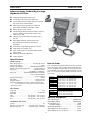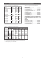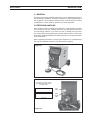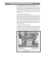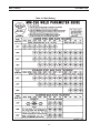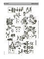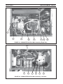
1
MIGMASTER 250 Plus
WELDING PACKAGES
INSTRUCTION MANUAL
This manual provides complete instructions for the following
power sources starting with Serial Number MxxJ239531
ESAB ITEM NO. 0558003215, Migmaster 250 Plus - 208/230 vac, 1 ph., 50/60 Hz
ESAB ITEM NO. 0558003216, Migmaster 250 Plus - 230/460/575 vac, 1 ph., 50/60 Hz
F15-728-D
09 / 2007
BE SURE THIS INFORMATION REACHES THE OPERATOR.
YOU CAN GET EXTRA COPIES THROUGH YOUR SUPPLIER.
These INSTRUCTIONS are for experienced operators. If you are not fully familiar with the principles
of operation and safe practices for arc welding and cutting equipment, we urge you to read our booklet,
"Precautions and Safe Practices for Arc Welding, Cutting, and Gouging," Form 52-529. Do NOT permit
untrained persons to install, operate, or maintain this equipment. Do NOT attempt to install or operate
this equipment until you have read and fully understand these instructions. If you do not fully
understand these instructions, contact your supplier for further information. Be sure to read the Safety
Precautions before installing or operating this equipment.
USER RESPONSIBILITY
This equipment will perform in conformity with the description thereof contained in this manual
and accompanying labels and/or inserts when installed, operated, maintained and repaired in
accordance with the instructions provided. This equipment must be checked periodically.
Malfunctioning or poorly maintained equipment should not be used. Parts that are broken, missing,
worn, distorted or contaminated should be replaced immediately. Should such repair or replacement become necessary, the manufacturer recommends that a telephone or written request for
service advice be made to the Authorized Distributor from whom it was purchased.
This equipment or any of its parts should not be altered without the prior written approval of the
manufacturer. The user of this equipment shall have the sole responsibility for any malfunction
which results from improper use, faulty maintenance, damage, improper repair or alteration by
anyone other than the manufacturer or a service facility designated by the manufacturer.
2
TABLE OF CONTENTS
SECTION NO.
................................................................................................................................ PAGE NO.
SECTION 1 - SAFETY PRECAUTIONS ........................................................................................................... 5
SECTION II - DESCRIPTION .......................................................................................................................... 11
2.1
2.2
2.3
2.4
2.5
GENERAL ............................................................................................................................................................. 13
RECEIVING-HANDLING ....................................................................................................................................... 13
DESCRIPTION ...................................................................................................................................................... 14
OPTIONAL ACCESSORIES ................................................................................................................................. 15
SAFETY ................................................................................................................................................................ 15
SECTION III - INSTALLATION ....................................................................................................................... 17
3.1
3.2
3.3
3.4
3.5
3.6
3.7
3.8
3.9
3.10
3.11
LOCATION ............................................................................................................................................................ 17
ELECTRICAL INPUT REQUIREMENTS ............................................................................................................... 17
ELECTRICAL INPUT CONNECTIONS ................................................................................................................. 17
INPUT VOLTAGE CHANGE-OVER CONNECTIONS .......................................................................................... 18
SECONDARY OUTPUT CONNECTIONS ............................................................................................................ 22
TORCH CONNECTIONS ...................................................................................................................................... 24
WELDING WIRE SPOOL ...................................................................................................................................... 24
WIRE FEEDER MECHANISM ............................................................................................................................... 25
BRAKE DRAG ADJUSTMENT .............................................................................................................................. 26
CONNECTION OF THE SHIELD GAS .................................................................................................................. 26
WELDING CABLE CONNECTIONS ..................................................................................................................... 27
SECTION IV - OPERATION ............................................................................................................................ 29
4.1
4.2
4.3
4.4
4.5
4.6
CONTROLS ........................................................................................................................................................... 29
OPERATING PROCEDURES ............................................................................................................................... 31
PROCESS SETUP ................................................................................................................................................ 32
WELDING OPERATION ........................................................................................................................................ 32
SPOOL GUN OPERATION/CONNECTION .......................................................................................................... 35
SPOT-STITCH OPERATION ................................................................................................................................ 36
SECTION V - MAINTENANCE ....................................................................................................................... 39
5.1
5.2
5.3
MAINTENANCE ....................................................................................................................................................39
INSPECTION AND SERVICE ............................................................................................................................... 39
TROUBLESHOOTING .......................................................................................................................................... 40
SECTION VI - REPLACEMENT PARTS ........................................................................................................ 49
3
TABLE OF CONTENTS
4
SECTION 1
SAFETY PRECAUTIONS
hazard.
6. After completing operations, inspect the work area to
make certain there are no hot sparks or hot metal which
could cause a later fire. Use fire watchers when necessary.
7. For additional information, refer to NFPA Standard 51B,
"Fire Prevention in Use of Cutting and Welding Processes", available from the National Fire Protection Association, Batterymarch Park, Quincy, MA 02269.
WARNING: These Safety Precautions are for
your protection. They summarize precautionary
information from the references listed in Additional Safety Information section. Before performing any installation or operating procedures,
be sure to read and follow the safety precautions listed below
as well as all other manuals, material safety data sheets,
labels, etc. Failure to observe Safety Precautions can result
in injury or death.
ELECTRICAL SHOCK -- Contact with live
electrical parts and ground can cause
severe injury or death. DO NOT use AC
welding current in damp areas, if movement is confined, or if there is danger of
falling.
PROTECT YOURSELF AND OTHERS -Some welding, cutting, and gouging processes are noisy and require ear protection. The arc, like the sun, emits ultraviolet (UV) and other radiation and can injure skin and
eyes. Hot metal can cause burns. Training in the proper
use of the processes and equipment is essential to
prevent accidents. Therefore:
1. Be sure the power source frame (chassis) is connected
to the ground system of the input power.
2. Connect the workpiece to a good electrical ground.
3. Connect the work cable to the workpiece. A poor or
missing connection can expose you or others to a fatal
shock.
4. Use well-maintained equipment. Replace worn or damaged cables.
5. Keep everything dry, including clothing, work area, cables,
torch/electrode holder, and power source.
6. Make sure that all parts of your body are insulated from
work and from ground.
7. Do not stand directly on metal or the earth while working
in tight quarters or a damp area; stand on dry boards or
an insulating platform and wear rubber-soled shoes.
8. Put on dry, hole-free gloves before turning on the power.
9. Turn off the power before removing your gloves.
10. Refer to ANSI/ASC Standard Z49.1 (listed on next page)
for specific grounding recommendations. Do not mistake
the work lead for a ground cable.
1. Always wear safety glasses with side shields in any work
area, even if welding helmets, face shields, and goggles
are also required.
2. Use a face shield fitted with the correct filter and cover
plates to protect your eyes, face, neck, and ears from
sparks and rays of the arc when operating or observing
operations. Warn bystanders not to watch the arc and not
to expose themselves to the rays of the electric-arc or hot
metal.
3. Wear flameproof gauntlet type gloves, heavy long-sleeve
shirt, cuffless trousers, high-topped shoes, and a welding
helmet or cap for hair protection, to protect against arc rays
and hot sparks or hot metal. A flameproof apron may also
be desirable as protection against radiated heat and sparks.
4. Hot sparks or metal can lodge in rolled up sleeves, trouser
cuffs, or pockets. Sleeves and collars should be kept
buttoned, and open pockets eliminated from the front of
clothing
5. Protect other personnel from arc rays and hot sparks with
a suitable non-flammable partition or curtains.
6. Use goggles over safety glasses when chipping slag or
grinding. Chipped slag may be hot and can fly far. Bystanders should also wear goggles over safety glasses.
ELECTRIC AND MAGNETIC FIELDS —
May be dangerous. Electric current flowing through any conductor causes localized Electric and Magnetic Fields (EMF).
Welding and cutting current creates EMF
around welding cables and welding machines. Therefore:
FIRES AND EXPLOSIONS -- Heat from
flames and arcs can start fires. Hot slag
or sparks can also cause fires and explosions. Therefore:
1. Welders having pacemakers should consult their physician before welding. EMF may interfere with some pacemakers.
2. Exposure to EMF may have other health effects which are
unknown.
3. Welders should use the following procedures to minimize
exposure to EMF:
A. Route the electrode and work cables together. Secure
them with tape when possible.
B. Never coil the torch or work cable around your body.
C. Do not place your body between the torch and work
cables. Route cables on the same side of your body.
D. Connect the work cable to the workpiece as close as
possible to the area being welded.
E. Keep welding power source and cables as far away
from your body as possible.
1. Remove all combustible materials well away from the work
area or cover the materials with a protective non-flammable covering. Combustible materials include wood,
cloth, sawdust, liquid and gas fuels, solvents, paints and
coatings, paper, etc.
2. Hot sparks or hot metal can fall through cracks or crevices
in floors or wall openings and cause a hidden smoldering
fire or fires on the floor below. Make certain that such
openings are protected from hot sparks and metal.“
3. Do not weld, cut or perform other hot work until the
workpiece has been completely cleaned so that there are
no substances on the workpiece which might produce
flammable or toxic vapors. Do not do hot work on closed
containers. They may explode.
4. Have fire extinguishing equipment handy for instant use,
such as a garden hose, water pail, sand bucket, or portable
fire extinguisher. Be sure you are trained in its use.
5. Do not use equipment beyond its ratings. For example,
overloaded welding cable can overheat and create a fire
5
SECTION 1
SAFETY PRECAUTIONS
EQUIPMENT MAINTENANCE -- Faulty or
improperly maintained equipment can
cause injury or death. Therefore:
FUMES AND GASES -- Fumes and
gases, can cause discomfort or harm,
particularly in confined spaces. Do
not breathe fumes and gases. Shielding gases can cause asphyxiation.
Therefore:
1. Always have qualified personnel perform the installation,
troubleshooting, and maintenance work. Do not perform
any electrical work unless you are qualified to perform
such work.
2. Before performing any maintenance work inside a power
source, disconnect the power source from the incoming
electrical power.
3. Maintain cables, grounding wire, connections, power
cord, and power supply in safe working order. Do not
operate any equipment in faulty condition.
4. Do not abuse any equipment or accessories. Keep
equipment away from heat sources such as furnaces,
wet conditions such as water puddles, oil or grease,
corrosive atmospheres and inclement weather.
5. Keep all safety devices and cabinet covers in position
and in good repair.
6. Use equipment only for its intended purpose. Do not
modify it in any manner.
1. Always provide adequate ventilation in the work area by
natural or mechanical means. Do not weld, cut, or gouge
on materials such as galvanized steel, stainless steel,
copper, zinc, lead, beryllium, or cadmium unless positive
mechanical ventilation is provided. Do not breathe fumes
from these materials.
2. Do not operate near degreasing and spraying operations. The heat or arc rays can react with chlorinated
hydrocarbon vapors to form phosgene, a highly toxic
gas, and other irritant gases.
3. If you develop momentary eye, nose, or throat irritation
while operating, this is an indication that ventilation is not
adequate. Stop work and take necessary steps to improve ventilation in the work area. Do not continue to
operate if physical discomfort persists.
4. Refer to ANSI/ASC Standard Z49.1 (see listing below)
for specific ventilation recommendations.
5. WARNING: This product, when used for welding or
cutting, produces fumes or gases which
contain chemicals known to the State of
California to cause birth defects and, in
some cases, cancer. (California Health &
Safety Code §25249.5 et seq.)
ADDITIONAL SAFETY INFORMATION -- For
more information on safe practices for electric arc welding and cutting equipment, ask
your supplier for a copy of "Precautions and
Safe Practices for Arc Welding, Cutting and
Gouging", Form 52-529.
The following publications, which are available from the
American Welding Society, 550 N.W. LeJuene Road, Miami, FL 33126, are recommended to you:
1. ANSI/ASC Z49.1 - "Safety in Welding and Cutting"
2. AWS C5.1 - "Recommended Practices for Plasma Arc
Welding"
3. AWS C5.2 - "Recommended Practices for Plasma Arc
Cutting"
4. AWS C5.3 - "Recommended Practices for Air Carbon Arc
Gouging and Cutting"
5. AWS C5.5 - "Recommended Practices for Gas Tungsten
Arc Welding“
6. AWS C5.6 - "Recommended Practices for Gas Metal Arc
Welding"“
7. AWS SP - "Safe Practices" - Reprint, Welding Handbook.
8. ANSI/AWS F4.1, "Recommended Safe Practices for
Welding and Cutting of Containers That Have Held
Hazardous Substances."
CYLINDER HANDLING -- Cylinders, if
mishandled, can rupture and violently
release gas. Sudden rupture of cylinder, valve, or relief device can injure or
kill. Therefore:
1. Use the proper gas for the process and use the proper
pressure reducing regulator designed to operate from
the compressed gas cylinder. Do not use adaptors.
Maintain hoses and fittings in good condition. Follow
manufacturer's operating instructions for mounting regulator to a compressed gas cylinder.
2. Always secure cylinders in an upright position by chain or
strap to suitable hand trucks, undercarriages, benches,
walls, post, or racks. Never secure cylinders to work
tables or fixtures where they may become part of an
electrical circuit.
3. When not in use, keep cylinder valves closed. Have valve
protection cap in place if regulator is not connected.
Secure and move cylinders by using suitable hand trucks.
Avoid rough handling of cylinders.
4. Locate cylinders away from heat, sparks, and flames.
Never strike an arc on a cylinder.
5. For additional information, refer to CGA Standard P-1,
"Precautions for Safe Handling of Compressed Gases in
Cylinders", which is available from Compressed Gas
Association, 1235 Jefferson Davis Highway, Arlington,
VA 22202.
MEANING OF SYMBOLS - As used throughout this manual: Means Attention! Be Alert!
Your safety is involved.
Means immediate hazards which, if
not avoided, will result in immediate,
serious personal injury or loss of life.
Means potential hazards which could
result in personal injury or loss of life.
Means hazards which could result in
minor personal injury.
6
SECTION 1
PRECAUCION DE SEGURIDAD
ADVERTENCIA: Estas Precauciones de Seguridad
5. No use el equipo fuera de su rango de operación. Por ejemplo, el
son para su protección. Ellas hacen resumen de
información proveniente de las referencias listadas
en la sección "Información Adicional Sobre La Seguridad". Antes de
hacer cualquier instalación o procedimiento de operación , asegúrese
de leer y seguir las precauciones de seguridad listadas a continuación
así como también todo manual, hoja de datos de seguridad del
material, calcomanias, etc. El no observar las Precauciones de
Seguridad puede resultar en daño a la persona o muerte.
calor causado por cable sobrecarga en los cables de soldar
pueden ocasionar un fuego.
6. Después de termirar la operación del equipo, inspeccione el área
de trabajo para cerciorarse de que las chispas o metal caliente
ocasionen un fuego más tarde. Tenga personal asignado para
vigilar si es necesario.
7. Para información adicional , haga referencia a la publicación
NFPA Standard 51B, "Fire Prevention in Use of Cutting and
Welding Processes", disponible a través de la National Fire
Protection Association, Batterymarch Park, Quincy, MA 02269.
PROTEJASE USTED Y A LOS DEMAS-Algunos procesos de soldadura, corte
y ranurado son ruidosos y requiren
protección para los oídos. El arco, como
el sol , emite rayos ultravioleta (UV) y
otras radiaciones que pueden dañar la piel y los ojos.
El metal caliente causa quemaduras. EL entrenamiento
en el uso propio de los equipos y sus procesos es
esencial para prevenir accidentes. Por lo tanto:
CHOQUE ELECTRICO -- El contacto con
las partes eléctricas energizadas y tierra
puede causar daño severo o muerte. NO
use soldadura de corriente alterna (AC)
en áreas húmedas, de movimiento
confinado en lugares estrechos o si hay
posibilidad de caer al suelo.
1. Utilice gafas de seguridad con protección a los lados siempre
1. Asegúrese de que el chasis de la fuente de poder esté conectado
que esté en el área de trabajo, aún cuando esté usando careta
de soldar, protector para su cara u otro tipo de protección.
Use una careta que tenga el filtro correcto y lente para proteger
sus ojos, cara, cuello, y oídos de las chispas y rayos del arco
cuando se esté operando y observando las operaciones. Alerte
a todas las personas cercanas de no mirar el arco y no exponerse
a los rayos del arco eléctrico o el metal fundido.
Use guantes de cuero a prueba de fuego, camisa pesada de
mangas largas, pantalón de ruedo liso, zapato alto al tobillo, y
careta de soldar con capucha para el pelo, para proteger el
cuerpo de los rayos y chispas calientes provenientes del metal
fundido. En ocaciones un delantal a prueba de fuego es
necesario para protegerse del calor radiado y las chispas.
Chispas y partículas de metal caliente puede alojarse en las
mangas enrolladas de la camisa , el ruedo del pantalón o los
bolsillos. Mangas y cuellos deberán mantenerse abotonados,
bolsillos al frente de la camisa deberán ser cerrados o eliminados.
Proteja a otras personas de los rayos del arco y chispas calientes
con una cortina adecuada no-flamable como división.
Use careta protectora además de sus gafas de seguridad cuando
esté removiendo escoria o puliendo. La escoria puede estar
caliente y desprenderse con velocidad. Personas cercanas
deberán usar gafas de seguridad y careta protectora.
a tierra através del sistema de electricidad primario.
2. Conecte la pieza de trabajo a un buen sistema de tierra física.
3. Conecte el cable de retorno a la pieza de trabajo. Cables y
conductores expuestos o con malas conexiones pueden exponer
al operador u otras personas a un choque eléctrico fatal.
4. Use el equipo solamente si está en buenas condiciones.
Reemplaze cables rotos, dañados o con conductores expuestos.
5. Mantenga todo seco, incluyendo su ropa, el área de trabajo, los
cables, antorchas, pinza del electrodo, y la fuente de poder.
6. Asegúrese que todas las partes de su cuerpo están insuladas
de ambos, la pieza de trabajo y tierra.
7. No se pare directamente sobre metal o tierra mientras trabaja en
lugares estrechos o áreas húmedas; trabaje sobre un pedazo de
madera seco o una plataforma insulada y use zapatos con suela
de goma.
8. Use guantes secos y sin agujeros antes de energizar el equipo.
9. Apage el equipo antes de quitarse sus guantes.
10. Use como referencia la publicación ANSI/ASC Standard Z49.1
(listado en la próxima página) para recomendaciones específicas
de como conectar el equipo a tierra. No confunda el cable de
soldar a la pieza de trabajo con el cable a tierra.
2.
3.
4.
5.
6.
CAMPOS ELECTRICOS Y MAGNETICOS
- Son peligrosos. La corriente eléctrica
fluye através de cualquier conductor
causando a nivel local Campos Eléctricos
y Magnéticos (EMF). Las corrientes en el
área de corte y soldadura, crean EMF
alrrededor de los cables de soldar y las
maquinas. Por lo tanto:
FUEGO Y EXPLOSIONES -- El calor de
las flamas y el arco pueden ocacionar
fuegos. Escoria caliente y las chispas
pueden causar fuegos y explosiones.
Por lo tanto:
1. Soldadores u Operadores que use marca-pasos para el corazón
1. Remueva todo material combustible lejos del área de trabajo o
deberán consultar a su médico antes de soldar. El Campo
Electromagnético (EMF) puede interferir con algunos marca-pasos.
2. Exponerse a campos electromagnéticos (EMF) puede causar
otros efectos de salud aún desconocidos.
3. Los soldadores deberán usar los siguientes procedimientos para
minimizar exponerse al EMF:
A. Mantenga el electrodo y el cable a la pieza de trabajo juntos,
hasta llegar a la pieza que usted quiere soldar. Asegúrelos uno
junto al otro con cinta adhesiva cuando sea posible.
B. Nunca envuelva los cables de soldar alrededor de su cuerpo.
C. Nunca ubique su cuerpo entre la antorcha y el cable, a la pieza
de trabajo. Mantega los cables a un sólo lado de su cuerpo.
D. Conecte el cable de trabajo a la pieza de trabajo lo más
cercano posible al área de la soldadura.
E. Mantenga la fuente de poder y los cables de soldar lo más lejos
posible de su cuerpo.
cubra los materiales con una cobija a prueba de fuego. Materiales
combustibles incluyen madera, ropa, líquidos y gases flamables,
solventes, pinturas, papel, etc.
2. Chispas y partículas de metal pueden introducirse en las grietas
y agujeros de pisos y paredes causando fuegos escondidos en
otros niveles o espacios. Asegúrese de que toda grieta y agujero
esté cubierto para proteger lugares adyacentes contra fuegos.
3. No corte, suelde o haga cualquier otro trabajo relacionado hasta
que la pieza de trabajo esté totalmente limpia y libre de
substancias que puedan producir gases inflamables o vapores
tóxicos. No trabaje dentro o fuera de contenedores o tanques
cerrados. Estos pueden explotar si contienen vapores inflamables.
4. Tenga siempre a la mano equipo extintor de fuego para uso
instantáneo, como por ejemplo una manguera con agua, cubeta
con agua, cubeta con arena, o extintor portátil. Asegúrese que
usted esta entrenado para su uso.
7
SECTION 1
PRECAUCION DE SEGURIDAD
MANTENIMIENTO DEL EQUIPO -- Equipo
defectuoso o mal mantenido puede causar
daño o muerte. Por lo tanto:
HUMO Y GASES -- El humo y los gases,
pueden causar malestar o daño,
particularmente en espacios sin
ventilación. No inhale el humo o gases.
El gas de protección puede causar falta
de oxígeno.
Por lo tanto:
1. Siempre tenga personal cualificado para efectuar l
a
instalación, diagnóstico, y mantenimiento
del
equipo. No ejecute ningún trabajo eléctrico a menos
que usted esté cualificado para hacer el trabajo.
2. Antes de dar mantenimiento en el interior de la
fuente de poder, desconecte la fuente de poder del
suministro de electricidad primaria.
3. Mantenga los cables, cable a tierra, conexciones, cable
primario, y cualquier otra fuente de poder en buen
estado operacional. No opere ningún equipo en
malas condiciones.
4. No abuse del equipo y sus accesorios. Mantenga el
equipo lejos de cosas que generen calor como
hornos, también lugares húmedos como charcos de
agua , aceite o grasa, atmósferas corrosivas y las
inclemencias del tiempo.
5. Mantenga todos los artículos de seguridad y coverturas
del equipo en su posición y en buenas condiciones.
6. Use el equipo sólo para el propósito que fue diseñado.
No modifique el equipo en ninguna manera.
1. Siempre provea ventilación adecuada en el área de
trabajo por medio natural o mecánico. No solde, corte, o
ranure materiales con hierro galvanizado, acero inoxidable,
cobre, zinc, plomo, berílio, o cadmio a menos que provea
ventilación mecánica positiva . No respire los gases
producidos por estos materiales.
2. No opere cerca de lugares donde se aplique substancias
químicas en aerosol. El calor de los rayos del arco pueden
reaccionar con los vapores de hidrocarburo clorinado para
formar un fosfógeno, o gas tóxico, y otros irritant es.
3. Si momentáneamente desarrolla inrritación de ojos, nariz
o garganta mientras est á operando, es indicación de que
la ventilación no es apropiada. Pare de trabajar y tome
las medidas necesarias para mejorar la ventilación en
el área de trabajo. No continúe operando si el malestar
físico persiste.
4. Haga referencia a la publicación ANSI/ASC Standard
Z49.1 (Vea la lista a continuación) para recomendaciones
específicas en la ventilación.
5. ADVERTENCIA-- Este producto cuando se utiliza para
soldaduras o cortes, produce humos
o gases, los cuales contienen
químicos conocidos por el Estado
de California de causar defectos en
el nacimiento, o en algunos casos,
Cancer. (California Health & Safety
Code §25249.5 et seq.)
INFORMACION ADICIONAL DE SEGURIDAD -Para más información sobre las prácticas de
seguridad de los equipos de arco eléctrico para
soldar y cortar, pregunte a su suplidor por una
copia de "Precautions and Safe Practices for Arc
Welding, Cutting and Gouging-Form 52-529.
Las siguientes publicaciones, disponibles através de la
American Welding Society, 550 N.W. LeJuene Road, Miami,
FL 33126, son recomendadas para usted:
1. ANSI/ASC Z49.1 - "Safety in Welding and Cutting"
2. AWS C5.1 - "Recommended Practices for Plasma Arc
Welding"
3. AWS C5.2 - "Recommended Practices for Plasma Arc
Cutting"
4. AWS C5.3 - "Recommended Practices for Air Carbon Arc
Gouging and Cutting"
5. AWS C5.5 - "Recommended Practices for Gas Tungsten
Arc Welding“
6. AWS C5.6 - "Recommended Practices for Gas Metal Arc
Welding"“
7. AWS SP - "Safe Practices" - Reprint, Welding Handbook.
8. ANSI/AWS F4.1, "Recommended Safe Practices for Welding and Cutting of Containers That Have Held Hazardous
Substances."
SIGNIFICADO DE LOS SIMBOLOS -Según usted avanza en la lectura de
este folleto: Los Símbolos Significan
¡Atención! ¡Esté Alerta! Se trata de su
seguridad.
Significa riesgo inmediato que, de no ser
evadido, puede resultar inmediatamente
en serio daño personal o la muerte.
MANEJO DE CILINDROS-- Los
cilindros, si no son manejados
correctamente, pueden romperse y
liberar violentamente gases. Rotura
repentina del cilindro, válvula, o
válvula de escape puede causar daño
o muerte. Por lo tanto:
1. Utilize el gas apropiado para el proceso y utilize un
regulador diseñado para operar y reducir la presión del
cilindro de gas . No utilice adaptadores. Mantenga las
mangueras y las conexiones en buenas condiciones.
Observe las instrucciones de operación del manufacturero
para montar el regulador en el cilindro de gas comprimido.
2. Asegure siempre los cilindros en posición vertical y
amárrelos con una correa o cadena adecuada
para
asegurar el cilindro al carro, transportes, tablilleros, paredes,
postes, o armazón. Nunca asegure los cilindros a la mesa
de trabajo o las piezas que son parte del circuito de
soldadura . Este puede ser parte del circuito elélectrico.
3. Cuando el cilindro no está en uso, mantenga la válvula del
cilindro cerrada. Ponga el capote de protección sobre la
válvula si el regulador no está conectado. Asegure y
mueva los cilindros utilizando un carro o transporte
adecuado. Evite el manejo brusco de los
Significa el riesgo de un peligro potencial
que puede resultar en serio daño personal o la muerte.
Significa el posible riesgo que puede
resultar en menores daños a la persona.
8
SECTION 1
PRÉCAUTIONS DE SÉCURITÉ
AVERTISSEMENT: Ces règles de sécurité ont pour objet
d’ assurer votre protection. Veillez à lire et à observer les
précautions énoncées ci-dessous avant de monter l’
équipement ou de commercer à l’utiliser. Tout défaut
d’observation de ces précautions risque d’entraîner des
blessures graves ou mortelles.
1. PROTECTION INDIVIDUELLE-- Les brûlures de la
peau et des yeux dues au rayonnement de l’arc
électrique ou du métal incandescent, lors du soudage
au plasma ou à l’électrode ou lors du gougeage à
l’arc, peuvent s’avérer plus graves que celles
résultant d’une exposition prolongée au soleil. Aussi
convient-il d’observer les précautions suivantes:
a. Portez un écran facial adéquat muni des plaques
protectrices et des verres filtrants appropriés afin de
vous protéger les yeux, le visage, le cou et les oreilles
des étincelles et du rayonnement de l’arc électrique
lorsque vous effectuez des soudures ou des coupes
ou lorsque vous en observez l’exécution.
AVERTISSEZ les personnes se trouvant à proximité
de façon à ce qu’elles ne regardent pas l’arc et à ce
qu’elles ne s’exposent pas à son rayonnement, ni à
celui du métal incandescent.
b. Portez des gants ignifugés à crispins, une tunique
épaisse à manches longues, des pantalons sans
rebord, des chaussures à embout d’acier et un
casque de soudage ou une calotte de protection, afin
d’éviter d’exposer la peau au rayonnement de l’arc
électrique ou du métal incandescent. ll est également
souhaitable d’utiliser un tablier ininflammable de
façon à se protéger des étincelles et du rayonnement
thermique.
c. Les étincelles ou les projections de métal incandescent
risquent de se loger dans des manches retroussées,
des bords relevés de pantalons ou dans des poches.
Aussi convient-il de garder boutonnés le col et les
manches et de porter des vêtements sans poches à
l’avant.
d. Protégez des étincelles et du rayonnement de l’arc
électrique les autres personnes travaillant à proximité
à l’aide d’un écran ininflammable adéquat.
e. Ne jamais omettre de porter des lunettes de sécurité
lorsque vous vous trouvez dans un secteur où l’on
effectue des opérations de soudage ou de coupage à
l’arc. Utilisez des lunettes de sécurité à écrans ou
verres latéraux pour piquer ou meûler le laitier. Les
piquetures incandescentes de laitier peuvent être
projetées à des distances considérables. Les
personnes se trouvant à proximité doivent également
porter des lunettes de protection.
f. Le gougeage à l’arc et le soudage à l’arc au plasma
produisent un niveau de bruit extrêmement élevé (de
100 à 114 dB) et exigent par conséquent l’emploi de
dispositifs appropriés de protection auditive.
2. PRÉVENTION DES INCENDES-- Les projections de
laitier incandescent
ou d’étincelles peuvent
provoquer de graves incendies au contact de
matériaux combustibles solides, liquides ou gazeux.
Aussi faut-il observer les précautions suivantes:
a. Éloigner suffisamment tous les matériaux combustibles
du secteur où l’on exécute des soudures ou des
coupes à l’arc, à moins de les recouvrir complètement
d’une bâche non-inflammable. Ce type de matériaux
comprend notamment le bois, les vêtements, la sciure,
l’essence, le kérosène, les peintures, les solvants, le
gaz naturel, l’acétylène, le propane et autres substances combustibles semblables.
b. Les étincelles ou les projections de métal incandescent
peuvent tomber dans des fissures du plancher ou
dans des ouvertures des murs et y déclencher une
ignition lente cachée. Veiller à protéger ces ouvertures
des étincelles et des projections de métal.
c. N’exécutez pas de soudures, de coupes, d’opérations
de gougeage ou autres travaux à chaud à la surface
de barils, bidons, réservoirs ou autres contenants
usagés, avant de les avoir nettoyés de toute trace de
substance susceptible de produire des vapeurs
inflammables ou toxiques.
d. En vue d’assurer la prévention des incendies, il
convient de disposer d’un matériel d’extinction prêt à
servir immédiatement, tel qu’un tuyau d’arrosage, un
seau à eau, un seau de sable ou un extincteur portatif.
e. Une fois le travail à l’arc terminé, inspectez le secteur
de façon à vous assurer qu’aucune étincelle ou projection de métal incandescent ne risque de provoquer
ultérieurement un feu.
3. CHOC ÉLECTRIQUE-- Le gougeage à l’arc et à l’arc
au plasma exige l’emploi de tensions à vide
relativement importantes; or, celles-ci risquent de
causer des dommages corporels graves et même
mortels en cas d’utilisation inadéquate. La gravité du
choc électrique reçu dépend du chemin suivi par le
courant à travers le corps humain et de son intensité.
a. Ne laissez jamais de surfaces métalliques sous tension
venir au contact direct de la peau ou de vêtements
humides. Veillez à porter des gants bien secs.
b. Si vous devez effectuer un travail sur une surface
métallique ou dans un secteur humide, veillez à assurer votre isolation corporelle en portant des gants secs
et des chaussures à semelles de caoutchouc et en
vous tenant sur une planche ou une plate-forme
sèche.
c. Mettez toujours à la terre le poste de soudage/coupage
en le reliant par un câble à une bonne prise de terre.
d. N’utilisez jamais de câbles usés ou endommagés. Ne
surchargez jamais le câble. Utilisez toujours un
équipement correctement entretenu.
e. Mettez l’équipement hors tension lorsqu’il n’est pas en
service. une mise à la masse accidentelle peut en effet
provoquer une surchauffe de l’équipement et un danger d’incendie. Ne pas enrouler ou passer le câble
autour d’une partie quelconque du corps.
f. Vérifiez si le câble de masse est bien relié à la pièce en
un point aussi proche que possible de la zone de
travail. Le branchement des câbles de masse à
l’ossature du bâtiment ou en un point éloigné de la
zone de travail augmente en effet le risque de passage
d’un courant de sortie par des chaînes de
9
SECTION 1
PRÉCAUTIONS DE SÉCURITÉ
qualité mais, chose plus grave encore, d’entraîner des
dommages corporels graves, voire mortels en
déclenchant des incendies ou des chocs électriques.
Observez par conséquent les précautions suivantes:
a. Efforcez-vous de toujours confier à un personnel qualifié l’installation, le dépannage et l’entretien du poste
de soudage et de coupage. N’effectuez aucune
réparation électrique sur l’équipement à moins d’être
qua-lifié à cet effet.
b. Ne procédez jamais à une tâche d’entretien
quelconque à l’intérieur du poste de soudage/
coupage, avant d’avoir débranché l’alimentation
électrique.
c. Maintenez en bon état de fonctionnement les câbles,
le câble de masse, les branchements, le cordon
d’alimentation et le poste de soudage/coupage.
N’utilisez jamais le poste ou l’équipement s’il présente
une défectuosité quelconque.
d. Prenez soin du poste de soudage et de coupage et des
équipements accessoires. Gardez-les à l’écart des
sources de charleur, notamment des fours, de
l’humidité, des flaques d’eau maintenez-les à l’abri des
traces d’huile ou de graisse, des atmosphères corrosives et des intempéries.
e. Laissez en place tous les dispositifs de sécurité et tous
les panneaux de l’armoire de commande en veillant à
les garder en bon état.
f. Utilisez le poste de soudage/coupage conformément à
son usage prévu et n’effectuez aucune modification.
6. INFORMATIONS COMPLÉMENTAIRES RELATIVES À
LA SÉCURITÉ-Pour obtenir des informations complémentaires sur les
règles de sécurité à observer pour le montage et
l’utilisation d’équipements de soudage et de coupage
électriques et sur les méthodes de travail
recommandées, demandez un exemplaire du livret N°
52529 “Precautions and Safe Practices for Arc Welding, Cutting and Gouging” publié par ESAB. Nous
conseillons également de consulter les publications
sui-vantes, tenues à votre disposition par l’American
Welding Society, 550 N.W. LeJuene Road, Miami, FL
32126:
a. “Safety in Welding and Cutting” AWS Z49.1
b. “Recommended Safe Practices for Gas-Shielded Arc
Welding “AWS A6. 1.
c. “Safe Practices for Welding and Cutting Containers
That Have Held Combustibles” AWS-A6.0.
d. “Recommended Safe Practices for Plasma Arc Cutting”
AWS-A6. 3.
e. “Recommended Safe Practices for Plasma Arc Welding” AWS-C5. 1.
f. “Recommended Safe Practices for Air Carbon Arc
Gouging and Cutting” AWS-C5. 3.
g. “Code For Safety in Welding and Cutting”
CSA-Standard W117. 2.
levage, des câbles de grue ou divers chemins
électriques.
g. Empêchez l’apparition de toute humidité, notamment
sur vos vêtements, à la surface de l’emplacement de
travail, des câbles, du porte-électrode et du poste de
soudage/coupage. Réparez immédiatement toute
fuite d’eau.
4. VENTILATION-- La respiration prolongée des fumées
résultant des opérations de soudage/coupage, à
l’intérieur, d’un local clos, peut provoquer des malaises et des dommages corporels. Aussi convient-il
d’observer les précautions suivantes:
a. Assurez en permanence une aération adéquate de
l’emplacement de travail en maintenant une ventilation naturelle ou à l’aide de moyens mécaniques.
N’effectuez jamais de travaux de soudage ou de
coupage sur des matériaux de zinc, de plomb, de
beryllium ou de cadmium en l’absence de moyens
mécaniques de ventilation capables d’empêcher
l’inhalation des fumées dégagées par ces matériaux.
b. N’effectuez jamais de travaux de soudage ou de
coupage à proximité de vapeurs d’hydrocarbure
chloré résultant d’opérations voisines de dégraissage
ou de pulvérisation. La chaleur dégagée ou le
rayonnement de l’arc peut déclencher la formation de
phosgène -- gaz particulièrement toxique -- et
d’autres gaz irritants, à partir des vapeurs de solvant.
c. Une irritation momentanée des yeux, du nez ou de la
gorge constatée au cours de l’utilisation de
l’équipement dénote un défaut de ventilation. Arrêtezvous de travailler afin de prendre les mesures nécessaires à l’amélioration de la ventilation. Ne poursuivez
pas l’opération entreprise si le malaise persiste.
d. Certaines commandes comportent des canalisations
où circule de l’hydrogène. L’armoire de commande est
munie d’un ventilateur destiné à empêcher la formation de poches d’hydrogène, lesquelles présentent un
danger d’explosion; ce ventilateur ne fonctionne que si
l’interrupteur correspondant du panneau avant se
trouve placé en position ON (Marche). Veillez à
manœuvrer cette commande en vérifiant si le
couvercle est bien en place, de façon à assurer
l’efficacité de la ventilation ainsi réalisée. Ne jamais
débrancher le ventilateur.
e. Les fumées produites par l’opération de soudage ou
de coupage peuvent s’avérer toxiques. Aussi est-il
nécessaire de disposer en permanence d’un dispositif
adéquat de ventilation de type aspirant, afin d’éliminer du voisinage de l’opérateur tout dégagement de
fumée visible.
f. Consultez les recommandations particulières en
matière de ventilation indiquées à l’alinéa 6 de la
norme Z49.1 de l’AWS.
5. ENTRETIEN DE L’ÉQUIPEMENT-- Un équipement
entretenu de façon défectueuse ou inadéquate risque
non seulement de réaliser un travail de mauvaise
10
SECTION 2
DESCRIPTION
Industrial Ready-To-Weld Mig Package
MigMaster 250 Plus
Rated 250 amps at 50% duty cycle
DC welding output from 30 to 280 amps
24 overlapping heat (voltage) steps for accurate
fine tuning of arc characteristics
Wire Feed speed range from 20 to 650 ipm;
pulse width modulated, solid state control
Built-in Spool-on-Gun control
Low and High inductance taps for better control of
short arc welding characteristics when using
Argon mix or CO2
Heavy-Duty Four Roll Drive for positive grip of
the wire
Solid State Contactor reduces down time
and maintenance related to mechanical
contactors
Convenient, Large Capacity Built-In Tool Box
Dual “Easy-On” Cylinder Tray
NAS Torch connector compatible with bayonet
style torches
Burnback adjustment Standard
Quiet operation
Specifications
Power Source
How to Order
Rated Output (DC CV) ............................ 250 amps @ 27volts
Open Circuit Voltage ...................................................... 55vdc
Primary Input Voltages* ................... 208/230/380/400/460/575
Primary Input Current @ 250A load: ........... 71/62/37/36/31/25
Duty Cycle ................................................. 208/230 Vac Model
..................................................... 50%@60Hz. / 40%@50Hz.
DutyCycle ...................... 208/230/380/400/460/575 Vac Model
........................................................ 35% for 208/230/380/400
...................................................................... 50% for 460/575
Output Current Range .................................................. 30-280
Net Weight ..................................................... 250 lbs.(113 Kg)
Shipping Weight ............................................. 260 lbs.(117 Kg)
Dimensions assembled w/ wheels, cylinder rack & Handles;
............. W=25 in.(64cm) x L=42 in.(107cm) x H=34 in.(86cm)
Each of the following packages includes the power source with
built-in wire feeder, factory installed undercarriage and cylinder rack, GunMaster 250 with NAS connector (bayonet), dual
groove driveroll (.035-.045), gas regulator/flowmeter, 6 ft. gas
hose, 15 ft. work cable and Mig Welding Handbook and free
spool of wire.
* Depending on Model
0558003491
0558003492
0558003493
0558003494
0558003495
0558003496
0558003497
0558003498
MigMaster 250 Plus - Ready-to-Weld Mig Packages
Migmaster 250 Plus - 12-ft, 208/230vac Argon
Migmaster 250 Plus - 15-ft, 208/230vac Argon
Migmaster 250 Plus - 12ft, 208/230vac CO2
Migmaster 250 Plus - 15ft, 208/230vac CO2
Migmaster 250 Plus - 12ft, 200-575vac Argon
Migmaster 250 Plus - 15ft, 200-575vac Argon
Migmaster 250 Plus - 12ft, 200-575vac CO2
Migmaster 250 Plus - 15ft, 200-575vac CO2
0558003499
0558003500
0558003501
0558003502
MigMaster 250 Plus - Spool-on-Gun Mig Packages
MM 250 Plus 230v 12'/ST-23A Argon
MM 250 Plus 230v 15'/ST-23A Argon
MM 250 Plus 575v 12'/ST-23A Argon
MM 250 Plus 575v 15'/ST-23A Argon
Wire Feeder
Feed Type ....................................................................... Push
Feed Rate ............................................................. 20-650 IPM
Wire Sizes
Hard ........................................ .023" (0.6mm) - .045" (1.2mm)
Cored ...................................... .030" (0.8mm) - 1/16" (1.6mm)
Soft .......................................... .035" (0.5mm) - 3/64" (1.2mm)
Optional Equipment
Spot, Stitch Option .................................. 0558003239
Digital Meter Option ................................ 0558003330
ST-23A Spool Gun ............................................ 19164
Requires Adapter ......................................... 37301
MT-250SG Spool Gun ...................................... 36779
Spool Spacer For 8" dia. spools ...................... 17511
Spool Spacer For 10" dia. spools ..................... 34330
GunMaster 250 Torch
Cooling ................................................................................ Air
Rating w/ Argon Mix Gas .............. 60% Duty Cycle - 200Amps
Rating w/ CO2 Gas ....................... 60% Duty Cycle - 300Amps
11
SECTION 2
DESCRIPTION
Table 2.1 - Drive Roll & Guide Tube Selection
Lower
Drive Roll
Upper
Pressure
Roll
Guide
Tube
21155
21155
21156
21156
21156
23612397
23612397
23612397
23612397
23612397
21163
21164
21165
21165
21165
Soft Wires (“U” groove)(aluminum)
.035 in. (0.9mm)
21158
3/64 in. (1.2mm)
21159
23612397
23612397
21167**
21168**
Cored Wires (Serrated “V” groove - lower)
.030 in. (0.8mm)
21160
.035 in. (0.9mm)
21160
.040 in. (1.0mm)
21161
.045 in. (1.2mm)
21161
.052 in. (1.4mm)
21161
1/16 in. (1.6mm)
21161
23612369
23612369
23612369
23612369
23612369
23612369
21164
21165
21165
21165
21166
21166
Wire Type /
Diameter
Hard Wires (“V” groove)
.023 in. (0.6mm)
.030 in. (0.8mm)
.035 in. (0.9mm)*
.040 in. (1.0mm)*
.045 in. (1.2mm)*
Cored Wires (Serrated “V” groove - upper & lower)†
.045 in. (1.2mm)
37319
37319
.052 in. (1.4mm)
37319
37319
1/16 in. (1.6mm)
37320
37320
*
**
†
Table 2.3 - Replacement Torch Nozzles
Standard Duty
No. 6 Nozzle, Tapered (3/8" I.D.) ...............
No. 8 Nozzle (1/2" I.D.), .............................
No. 10 Nozzle (5/8" I.D.) ............................
No. 12S Spotweld Nozzle (3/4" I.D.) ..........
Heavy-duty:
No. 8 Nozzle (1/2" I.D.) ..............................
No. 10 Nozzle (5/8" I.D.) ............................
No. 12 Nozzle (3/4" I.D.) ............................
No. 12 Spot Nozzle (3/4" I.D.) ....................
Long Life
No. 6 XL Nozzle, (MT Std.) ........................
No. 8 XL Nozzle, (MT Std.) ........................
No. 10 XL Nozzle, (MT Std.) ......................
No. 8 XL Nozzle, (MT HD) .........................
No. 10 XL Nozzle, (MT HS) .......................
21165
21166
21166
Table 2.2 - GunMaster-250 Torch Accessories
Contact Tips
Short (S) Medium (M) Long (L)
Hard Wires & Cored Wires
.023" (.6mm)
20543
.030" (.8mm)
20544
.035" (.9mm)
996995
.040" (1.0mm)
37287
.045" (1.2mm) 999578
37290
.052" (1.4mm) 948340
2075349
1/16" (1.6mm) 948341
37289
Soft Wires (aluminum)
.035" (.9mm)
.040" (1.0mm)
3/64" (1.2mm) 999578
(S)
(M)
(L)
*
996995
37287
996999
P/N 999471
P/N 999472
P/N 999473
P/N 999625
New Long Life MT Nozzles have a patented coating
to reduce weld spatter and extend the life of the
nozzle.
Supplied with Migmaster 250 Plus.
Requires Support Tube 21169.
Recommended for use with soft cored wires that are easy to flatten.
Wire
Size & Type
P/N 998895
P/N 998893
P/N 998894
P/N 17316
10'
Liners
12'
15'
999742
996994
996996
37288
996998
-
999743*
948850
2075237
17717
17718
2075238
2075237
2075239
2075239
17718
17719
17719
2075238
2075240
2075240
996996
37288
996998
948862
-
-
948863
-
-
Short contact tips are recommended for proper wire stick out for flux cored wire welding.
Medium contact tips are recommended for proper wire stick out in spray transfer Mig welding.
Long contact tips are recommended for good visibility and proper wire stick in dip transfer Mig welding.
Requires support liner for .023" wire. Order P/N 999797.
New ID for improved arc performance on steel/flux cored wire.
12
998895XL
998893XL
998894XL
999471XL
999472XL
SECTION 2
DESCRIPTION
2.1 GENERAL
This manual has been prepared especially for use in familiarizing personnel
with the design, installation, operation, maintenance, and troubleshooting of
this equipment. All information presented here in should be given careful
consideration to assure optimum performance of this equipment.
2.2 RECEIVING-HANDLING
Upon receipt and prior to installing this equipment, clean all packing material
from around the unit and carefully inspect for any damage that may have
occurred during shipment. Any claims for loss or damage that may have
occurred in transit must be filed by the purchaser with the carrier. A copy of the
bill of lading and freight bill will be furnished by the carrier on request if occasion
to file claim arises.
When requesting information concerning this equipment, it is essential that
Part, Serial and Model Numbers of the equipment be supplied.
Figure 2.1
For future convienence, record
Stock Number & Serial Number
Information here:
Data
Plate
Console Stock Number
Serial
Number
Plate
Serial Number
Figure 2.2
13
SECTION 2
DESCRIPTION
2.3 DESCRIPTION
The Migmaster 250 Plus is a portable compact welding system designed for
fine wire, (.023, .030, .035 and .045 in.) welding using the short arc method, as
well as for spray arc aluminum, short arc and spray arc stainless steel and spray
arc cored wires. It incorporates a four roll heavy duty wire drive, running gear
with provisions for two gas cylinders, tool compartment, and a ST-23A/MT250SG spool-on-gun control.
2.3.1 POWER SUPPLY
The power supply consists of a tapped single phase transformer, tap selection
switches, secondary contactor, single phase full wave rectifier, stabilizing
reactor with high and low taps, slope resistor, filtering capacitors and internal
output connections for polarity reversal.
2.3.2 WIRE FEEDER
The wire feeder pushes .023, .030, .035 and .045 in. wire at speeds up to 650
IPM. Dynamic braking prevents excessive wire overrun. A double grooved drive
rolls (.035 and .045 in. - supplied) provides a convenient means of changing the
setup for either wire size.
The wire feeder is built into the power supply cabinet, and is housed in a
compartment separated from the welding machine components. Machine
ventilation is not drawn through this compartment, thus helping to keep the wire
and feeding mechanism clean.
2.3.3 GUNMASTER 250 WELDING TORCH (see F15-612)
The lightweight air cooled welding gun included in selected systems is supplied
complete and ready to weld .035 in. steel wire. It is built with a one piece service
conduit and includes a 45 degree gooseneck. Changing the contact tip to .045
in. allows the use of the larger wire.
2.3.4 CONTROLS
The built-in spool-on-gun adaptor and control, when used in conjunction with the
optional ST-23A or MT-250GS torch, permits the use of aluminum wire welding
with the machine. An optional spot/stitch control allows a welder to spot or stitch
weld within a range of 0.4 to 3.5 seconds.
2.3.5 RUNNING GEAR
The Migmaster 250 Plus is equipped with a running gear w/swiveled front
wheels and a gas cylinder support. The cylinder rack has been especially
designed to accomodate "easy on" cylinder mounting for added convienence.
14
SECTION 2
DESCRIPTION
2.4 OPTIONAL ACCESSORIES
2.4.1 SPOT/STITCH/ANTI-STICK MODULE, P/N 0558003239
This easy-to-install, plug-in module mounts inside the feeder compartment and
replaces the original factory installed Burnback module. This module enables
the operator to use the Migmaster 250 Plus for Spot or Stitch or Continuous
welding operations. It also includes an adjustable Anti-Stick feature that allows
the selection of various wire burnback times to prevent wire from sticking in the
weld pool at the end of a weld. For operating instructions see Section 4.6.
If this module is ordered to perform Spot welding operations, it is recommended
that you also order a #12S Spotweld Nozzle. See the welding torch sales
catalog page for available nozzle options.
2.4.2 DIGITAL VOLT/AMMETER MODULE, P/N 0558003330
This easy-to-install, plug-in module mounts in place of the original front panel
of the electronics module. This unique meter module alternately displays
welding voltage and current (of the dial-set welding condition) every 4-seconds.
Two L.E.D.’s labeled Amps and Volts provided below the meter windows,
alternately illuminate to indicate which condition is being displayed. The
voltage indication is displayed in 1/10-volt increments (e.g.: 20.5), while the
current indication is usually displayed in three-whole digits (e.g.: 225). After the
torch trigger is released, the meter will continue to flash for 20-seconds the last
condition used during welding. At the end of this time, the meter will reset to
zero.
Figure 2.3 - Digital Volt/Ammeter Panel, PN 0558003330
15
SECTION 2
DESCRIPTION
2.4.3 ST-23A SPOOL-ON-GUN TORCH, P/N 19164 (see F14-353)
The Migmaster 250 Plus unit is equipped with a built-in control for the ST-23A
Spool-On-Gun welding torch. The ST-23A is a high performance, 250 ampere
continuous duty spool-on-gun torch designed for the mig welding process. It is
completely portable (up to 30-ft.), air-cooled and hand operated, and weighs
less than three (3) pounds. The gun is equipped with lines that are 30 feet long.
For installation and operation, see Section 4.5.
2.4.4 MT-250GS SPOOL-ON-GUN TORCH, P/N 36779 (see F15-380)
The Migmaster 250 Plus unit is equipped with a built-in control for the MT250GS Spool-On-Gun welding torch. The air-cooled ST-23A is a medium duty,
200 ampere continuous duty spool-on-gun torch designed for the mig welding
process. The gun is equipped with lines that are 25 feet long. For installation
and operation, see Section 4.5.
2.5 SAFETY
Before the equipment is put into operation, the safety section at the front of this
manual should be read completely. This will help avoid possible injury due to
misuse or improper welding applications.
The symbol
which precedes safety notes appearing throughout this
manual means “Attention! Be Alert! Your safety is involved.” The definitions
relating to the DANGER, WARNING and CAUTION safety notations are
described at the end of the Safety Section in the front of this manual -- read them
and their specific text references carefully.
16
SECTION 3
INSTALLATION
III. INSTALLATION
Only qualified personnel should make
these changes. Make certain the primary power has been disconnected and
all safety procedures have been followed before proceeding with these instructions.
Do not place any filtering device over
the intake air passages of the welding
machine as this would restrict the volume of intake air and thereby subject
the welding machine internal components to an overheating condition and
subsequent failure. Warranty is void if
any type of filtering device is used.
This manual has been prepared for use by an experienced operator. It provides
information to familiarize the operator with the design, installation and operation
of the Migmaster 250 Plus model power source. DO NOT attempt to install or
operate this equipment until you have read and fully understand these
instructions. The information presented here should be given careful
consideration to ensure optimum performance of this equipment.
3.1 LOCATION
A proper installation site should be selected for the welding machine, if the unit
is to provide dependable service and remain relatively maintenance free.
A proper installation site permits freedom of air movement into and out of the
welding machine, and also least subjects the unit to dust, dirt, moisture, and
corrosive vapors. A minimum of 18 inches (46 cm) unrestricted space must be
maintained between the welding machine side, rear panels and the nearest
obstruction.
The installation site should also permit easy removal of the welding machine
outer enclosure for maintenance functions.
If a forklift vehicle is used for lifting the unit, be sure that the lift forks are long
enough to extend completely under the base.
3.2 ELECTRICAL INPUT REQUIREMENTS
Before making electrical input
connections to the welding machine,
“Machinery Lockout Procedures” must
be employed. If the connections are to
be made from a line disconnect switch,
the switch should be padlocked in the
off position. If the connection is made
from a fusebox, remove the fuses from
the box and padlock the cover in the
closed position. Attach a red tag to the
line disconnect switch (or fuse box) to
warn others that the circuit is being
worked on. If the plug-cap is used,
remove plug from receptacle.
The Migmaster 250 Plus is available in either a dual voltage model designed
to be operated from single phase 208/230Vac 50/60Hz., or a multi-voltage
model designed to operate from single phase 208/230/380/400/460/575 Vac
50/60Hz.. The primary input voltage requirements are shown on the welding
machine nameplate.
3.3 ELECTRICAL INPUT CONNECTIONS
3.3.1 208/230 Vac 50/60 Hz. Model
The input power cord on dual voltage model (208/230) Volts primary input
model is provided with an attachment plugcap. The plugcap will mate with a 250
Volts, 50 Ampere receptacle conforming to NEMA 6-50 R configuration.
The receptacle should be wired to a separately fused disconnect or circuit
breaker (FIG. 3.1). This disconnect or breaker can be wired to a single phase
system or to two conductors of a three phase system. A third conductor for
grounding should also be connected between the disconnect and the receptacle.
The primary power leads must be insulated copper conductors. Either rubber
covered cable or conduit (flexible or solid) may be used. Table 3-1 provides
recommended input conductors and line fuse sizes.
3.3.2 208/230/380/400/460/575 Vac 50/60 Hz. Model
The 208/230/380/400/460/575 primary input voltage unit is provided with a
three conductor primary input cable without plugcap. This cable may be fitted
with a suitable user supplied plugcap or may be connected directly into the
fused disconnect box. If connecting directly to the fused disconnect box, the
ground conductor of this cable must be connected to a reliable earth ground.
The white and black conductors of this cable must be connected to the
separately fused lines of the disconnect or breaker as shown in Figures 3.1.
17
SECTION 3
INSTALLATION
Table 3.1 Input Conductor and Fuse Size
Recommended
It is recommended that a line disconnect switch be installed in the input
circuit to the welding machine. This
would provide a safe and convenient
means to completely remove all electrical power from the welding machine
whenever it is necessary to perform any
internal function on the unit.
Primary
Input
Volts
Full
Load
Line
Amperes
208
230
380
400
460
575
71
62
37
36
31
25
SUPPLY
SINGLE-PHASE
Fuse
Size
Primary
Input
Conductor
Size
Ground
Conductor
Size
90
90
50
50
40
30
8
8
10
10
12
12
8
8
10
10
12
12
THREE-PHASE
SUPPLY
Typical Plug and Receptacle
for 208/230 Vac models
Figure 3.1 - Typical Configuration - Customer Supplied Fused Line Disconnect Switch,
Wall Receptacle and Plug - Single or Three Phase.
3.4 INPUT VOLTAGE CHANGE-OVER CONNECTIONS
All machines leave the factory with their primary electrical input requirements
internally-connected for the highest voltage rating available in each model
(e.g.: 230-volt for the 208/230-volt units; and 575-volt for the "multi-voltage"
units).
Before switching the voltage taps, verify the actual voltage requirement as well
as the current voltage connection to be certain re-connection is necessary. If
voltage tap re-connection is necessary, the following paragraphs cover the
procedure to switch the voltage taps to the desired input configuration.
18
SECTION 3
INSTALLATION
3.4.1 CHANGE-OVER for the 208/230 Vac 50/60 Hz. Model
Fig. 3.2 shows the 230v and 208v connections for the 208/230 dual voltage
model. Change over is made by removing the right side panel below the wire
feed compartment and switching the primary transformer tap at the pigtail from
the top of the power switch with the unused alternate voltage tap located next
to the main transformer. Both voltage taps (the one currently connected to the
switch and the unused alternate voltage) are marked with the input voltage
requirement. All units are supplied from the factory connected for the highest
voltage (230 vac).
3.4.1A CONNECTING FOR 208 VAC INPUT
Remove the side panel and locate the 208 Vac lead (Fig. 3.2 & 3.4). Cut the tiewrap to remove the insulation sleeving. Cut the tie-wraps on the insulation
sleeving covering the 230 Vac connection to the pigtail lead from the power
switch. Expose the terminals buy sliding the sleeving over the pigtail toward the
power switch. Disconnect the 230 Vac lead from the pigtail as shown in Fig. 3.3
and connect the 208 Vac lead using the same hardware. Tighten securely.
Slide the insulation sleeving back over the lug connection and secure with tiewraps. Insulate the 230 Vac lead with sleeving removed from the 208 Vac tap
and re-position to a safe area beside the transformer (see Fig. 3.2), leaving a
minimum of one inch clearance from other components and the side panel.
Replace the side panel.
3.4.1B CONNECTING FOR 230 VAC INPUT
After the panel is removed, locate the 230 Vac lead (Fig. 3.2 & 3.4) and cut the
tie-wrap to remove the insulation sleeving. Cut the tie-wraps on the insulation
sleeving covering the 208 Vac connection to the pigtail lead from the power
switch. Expose the terminals buy sliding the sleeving over the pigtail toward the
power switch. Disconnect the 208 Vac lead from the pigtail as shown in Fig. 3.3
230Vac Tap Connection to the
ON/OFF Switch Pigtail
(Factory Supplied Configuration)
Figure 3.2
19
208Vac Tap Connection Un-used
with Protective Insulation
(Factory Supplied Configuration)
Input Voltage Change-Over Connections for the
208/230 Vac Model
SECTION 3
INSTALLATION
and connect the 230 Vac lead using the same hardware. Tighten securely.
Slide the insulation sleeving back over the lug connection and secure with tiewraps. Insulate the 208 Vac lead with sleeving removed from the 230 Vac tap
and re-position to a safe area beside the transformer (see Fig. 3.2), leaving a
minimum of one inch clearance from other components and the side panel.
Replace the side panel.
When changing the input voltage connections, the unused lead must be insulated and positioned to prevent contact
with any other internal components of
the machine or the machine side panel.
The clearance between the unused lead
and other components must be at least
one inch. FAILURE TO INSULATE AND
POSITION THIS LEAD PROPERLY WILL
CAUSE A SERIOUS SHOCK HAZARD.
230Vac Tap Disconnected ready
for insulation to be replaced.
Figure 3.3
Figure 3.4
208Vac Tap Connected to the
ON/OFF Switch Pigtail ready for
insulation to be replaced.
Change-Over Connections Exposed
208/230 Vac Model
Input Voltage Change-Over Connections for the
208/230 Vac Model
20
SECTION 3
INSTALLATION
3.4.2 CHANGE-OVER for the 208/230/380/400/460/575 Vac Model
Figures 3.5.a-f show how to reconfigure the "multi-voltage" model from the
factory-connected 575-volt input to other available voltage inputs (208, 230,
380, 400, or 460 volts). The voltage change-over terminal board is located
inside the tool compartment on the left side of the machine. The board contains
copper links and a flex jumper which must be reconnected to match the voltage
designation for the input you plan to use. To gain access, remove the screw
from the upper left corner and swing the plexiglass cover clockwise. Do not
remove the screw in the right-hand corner. Once the links have been
changed to the proper configuration be sure to close the cover and secure
in place.
Figure 3.5a - Input Voltage Links
575Vac Link Configuration
(Factory Supplied)
Figure 3.5b - Input Voltage Links
460Vac Link Configuration
Figure 3.5d - Input Voltage Links
380Vac Link Configuration
Figure 3.5c - Input Voltage Links
400Vac Link Configuration
Figure 3.5f - Input Voltage Links
208Vac Link Configuration
Figure 3.5e - Input Voltage Links
230Vac Link Configuration
21
SECTION 3
INSTALLATION
3.5 SECONDARY OUTPUT CONNECTIONS
The Migmaster 250 Plus Welding System is a completely self-contained
welding system that features the welding output receptacles conviently located
on the front panel to allow easier setup of the weld polarity. Two levels of
Inductance are available to fine tune arc characteristics for specific applications
and shield gases. To set up the system for welding, simply connect the torch
pigtail to the apropriate output receptacle for the polarity desired and Inductance.
To change the polarity, simply reverse the torch pigtail and the work cable plug
on the front panel of the machine.
D.C. Reverse Polarity (Electrode Positive) is generally used for all solid wire
applications in the short circuiting arc and spray arc mode.
D.C. Straight Polarity (Electrode Negative) is generally used for all self shielded
flux-core wire applications and some specialized gas shielded flux-core
applications.
(+) Positive
Output
Connections
Gun Pigtail
Connection
(-) Negative
Output
Connection
Gunmaster 250
NAS Connection
Work Cable
with Clamp
Gunmaster 250
Figure 3.6 Secondary Connections
Positive (+) Polarity
Output Receptacle
High Inductance
Positive (+) Polarity
Output Receptacle
Low Inductance
Welding Gun Pigtail
Connection
Negative (-) Polarity
Output Receptacle
Figure 3.7 SecondaryOutput Connections
22
SECTION 3
INSTALLATION
Figure 3.8 Output Connections for DCEP (Reverse Polarity) Operation
Figure 3.9 Output Connections for DCEN (Straight Polarity) Operation
Selecting the proper Inductance for a specific application and shield gas is
mostly a matter of personal preference. The Inductance setting will change the
crispness of the welding arc and change bead shape by affecting the weld pool
fluidity. Table 3.2 is a general guide to setting Inductance level.
Table 3.2 Recommended Output Inductance Tap Connections for Short-Arc Welding
Stainless Steel
Solid Wires
Welding
Current
Carbon Steels Solid W ires
Helium/Argon
Based Shielded
Gases
CO2
Shielding Gas
Argon Based Shielding Gases
All Wire Diameters .023" (0.6mm) .030" (0.8mm) .035" (0.9mm) .045" (1.2mm)
All Wire
Diameters
< 100 amps
high tap
high tap
high tap
high tap
high tap
low tap
125 amps
high tap
high or low*
high or low*
high or low*
high or low*
low tap
150 amps
high tap
NR
low tap
low tap
low tap
low tap
> 200 amps
high tap
NR
NR
low tap
low tap
low tap
Notes:
The above chart shows the recommended output inductance tap connection for Mig Short Circuiting Transfer.
For Mig Spray Arc Transfer (stainless or carbon steel) - use low tap
For Flux Cored Wire (all types) - use low tap
NR - Not Recommended
* The best connection (high tap or low tap) depends on the specific welding application and personal preference.
23
SECTION 3
INSTALLATION
3.6 TORCH CONNECTIONS
The GUNMASTER 250 supplied with the Migmaster 250 Plus System is
provided with a NAS type adapter which directly connects to the torch fitting
mounted on the front panel. Line up the power pin, push on and tighten locking
screw. To connect a spool-on-gun torch (ST-23A/MT-250GS) see Section 4.5.
Gunmaster
Retaining Screw
Gunmaster
Receptacle
Trigger Lead
Receptacle
Spool Gun Control
Cable Receptacle
Figure 3.10 Torch Connections
3.7 WELDING WIRE SPOOL
Install a spool of welding wire on the hub as follows:
A. Remove the retaining pin from spool hub.
B. Place wire spool on hub to rotate clockwise as wire is unwound;
hub pin must engage hole in spool.
C. Replace the retaining pin.
Spool Retaining
Clip
Power supply contactor becomes energized the moment the torch trigger is
depressed. Arcing can occur if the wire
is brought to a ground. Keep the torch
away from ground until welding is to
begin.
Spool Break Drag
Adjustment Screw
Spool Rotation
Figure 3.11 Fitting the Wire Spool
24
SECTION 3
INSTALLATION
3.8 WIRE FEEDER MECHANISM
3.8.1 DRIVE ROLLS
The drive roll has two grooves: the small groove feeds 0.035 in. diameter wire,
the large groove feeds 0.045 in. wire. The groove nearest the gear motor feeds
the wire. If the required groove is not in that position:
A. Release the drive roll pressure adjustment lever and lift the upper
drive roll assembly arm upward.
B. Remove the drive roll guard retaining screw and remove the guard.
C. Remove the two (2) screws holding the lower drive rolls to the gear.
D. Reverse the drive roll on the drive roll shaft.
E. Replace the drive roll retaining screws and tighten.
F. Lower the upper drive roll assmebly and secure the drive roll pressure
lever. Adjust pressure as required - DO NOT OVER TIGHTEN.
G. Replace the drive roll guard and tighten the retaining screw.
Upper Drive Roll
Assembly Arm
Drive Roll
Retaining Screws
Drive Roll Pressure
Adjustment Lever
Drive Roll Gaurd
Gaurd Retaining Screw
Figure 3.12 Wire Drive Stand
3.8.2 THREADING WELDING WIRE
A. Turn off power switch.
B. Release upper drive roll pressure assembly and lift upward. Check that
proper wire diameter groove is in the inner position.
CAUTION: Before threading welding wire through casing, make sure chisel
point and burrs have been removed from wire end to prevent wire
from jamming in gun casing or liner.
25
SECTION 3
INSTALLATION
Lift Upper Drive
Roll Assembly
Drive Roll Pressure
Adjustment Lever
Reel Hub
Spool Retaining Pin
As with any work area, make sure safety
glasses with side shields are worn when
handling or changing wire or clipping
wire off at the spool or at the end of the
torch. Hold onto the wire coming off the
spool with one hand before clipping.
Serious eye injury can result due to the
springiness of the wire which can
quickly unravel, or a cut wire end which
may shoot across the room.
Outlet
Guide
Center
Guide
Inlet
Guide
Thread the wire from
bottom of wire spool
Spool Brake
Adjustment Screw
Figure 3.13 Threading the Wire
C. Feed the wire from the spool through the inlet guide, across the drive
roll groove, through the center guide and into gun outlet guide.
When the power switch is on, and gun
trigger is depressed, the electrode wire
becomes electrically hot, and the wire
feed rolls are activated.
Make sure that the proper “outlet guide tube” is inserted into the frontpanel gun fitting for the size and type of wire being used, see Table 2.1
for wire feed accessories.
To insure proper wire feeding, it is important that the wire be kept clean
and that the drive rolls be periodically cleaned of any chips or scale that
might be carried into the gun liner and cause sticking.
D. Lower pressure roll assembly and secure. Check that the gears mesh.
Feed wire through to gun tip with gun trigger (power ON).
3.9 SPOOL BRAKE ADJUSTMENT
Brake disc friction should provide enough drag to keep the wire spool or coil from
spinning freely after wire feed stops. If adjustment is required, turn adjusting
screw clockwise to increase drag, counterclockwise to decrease it. Drag should
be just low enough to limit wire overrun.
3.10 CONNECTION OF SHIELDING GAS SUPPLY
Do Not adapt R-33-FM-580 for use with
CO2. Relief device may rupture if CO2 is
used with the R-33-FM-580. For CO2 service, order R-33-FM-320, P/N 21558.
Never stand directly in front of or behind
the regulator when opening the cylinder
valve. Always stand to one side.
The R-33-FM Regulator-Flowmeter is designed for use with high pressure
cylinders of shielding gas. It is adjustable for delivering up to 50 cfh through the
torch. To set up the system do the following:
A. With the cylinder cap in place CAREFULLY slidethe cylinder of gas
onto the Migmaster 250 Plus cylinder rack.
B. Secure the cylinder to the unit, using the chain provided.
C. Unscrew the cylinder cap.
D. Be sure to keep your face away from the valve outlet to protect
your eyes. Crack the cylinder valve slightly, just for an instant, to blow
away any dirt or dust which may have accumulated in the cylinder valve
outlet.
26
SECTION 3
For R-33-FM-320 Flowmaster be sure to
install fiber washer between union nut
and cylinder valve seat.
If welding is performed in a confined
area, shielding gas leaks could result in
a buildup of shielding gas concentration, displacing oxygen, thereby endangering personnel entering the area.
INSTALLATION
E. Attach the regulator to the cylinder valve, tighten the union nut securely
with a 1-1/8in. open end or an adjustable wrench.
F. Attach the gas hose from the rear of the Migmaster 250 Plus to the
regulator outlet connection (see Fig. 3.14).
G. Slowly open the cylinder valve a fraction of a turn. When the regulator
pressure gauge pointer stops moving, open the cylinder valve fully.
H. Using a leak test solution, such as P/N 998771 (8 oz. container) or
soapy water, test for leakage about the cylinder valve stem, the
regulator inlet connection, and the hose connections at the regulator
and at the Migmaster 250 Plus for leakage. Correct any leaks before
starting work.
I. If work is to be stopped for a half-hour or more, or the regulator is to be
removed from the cylinder, shut down the regulator as follows:
a. Close the cylinder valve.
b. Release gas from the regulator by closing the torch trigger lever.
c. When pressure gauge drops to zero, the regulator is de-pressurized and shutdown.
J. Each regulator is equipped with a porous metal inlet filter, P/N 71Z33,
pressed into the regulator inlet nipple. No regulator should be connected to a cylinder or station valve unless it contains this filter. You can
replace the filter if you have reason to do so. To remove a filter refer to
the regulator instruction literature for details.
K. Regulators in need of repair should be returned to your Welding
Equipment distributor or to an authorized Remanufacturing Center.
CYLINDER
VALVE
CYLINDER
PRESSURE
GAUGE
OUTLET
CONNECTION
Figure 3.14 R-33-FM-580 Regulator
3.11 WELDING CABLE CONNECTIONS
A good electrical connection to the work
is essential to proper welding operation
and to prevent electric shock.
Connect the work clamp solidly to the workpiece or work table. Clamp onto a
bare metal area.
Welding cables should be kept as short as possible and be of adequate current
carrying capacity. Resistance of the welding cables and connections causes a
voltage drop which is added to the voltage drop of the arc. Excessive cable
resistance may result in a reduction of the maximum usable current output of the
equipment.
The proper operation of this equipment is to a large extent dependent on the use
of welding cables and connections which are in good condition and of adequate
size.
27
SECTION 3
INSTALLATION
28
SECTION 4
OPERATION
IV. OPERATION
4.1 CONTROLS (See Figure 4.1)
Wire Feed
Speed Control
Wire Feed Mode
Switch
Standard / Spool Gun
Fine Voltage
Control Selector
Gunmaster
Power Receptacle
Coarse Voltage
Range Selector
Gunmaster
Trigger Receptacle
ST-23 Spool Gun
Control Receptacle
(+) Positive Output
Receptacle
HIGH Inductance
(+) Positive Output
Receptacle
LOW Inductance
(-) Negative Output
Receptacle
Power
ON/OFF
Switch
Torch Power
Plug
Figure 4.1 - Location of Controls
CAUTION:
These tap switches carry several
hundred amperes, and must not
be switched under load, as this will
cause the contacts of the switches
to arc.
4.1.1 POWER SWITCH
A line toggle switch on the front panel energizes the primary of the main
transformer. This switch also turns on the fan, which is connected across a
portion of the primary winding.
Two transformer secondary windings also become energized:
A. Gun trigger circuit 24 volts AC.
Wire feeder circuit 24 volts DC.
B. Main welding secondary circuit. Depending upon the tap switch position,
various secondary voltages can be obtained. Then rectified, open circuit
voltages can be selected between 18 and 56 volts DC when the secondary
contactor is energized.
29
SECTION 4
OPERATION
4.1.2 VOLTAGE CONTROL (Coarse Range Selector and Fine Adjustment
Range Selector)
Voltage control is by means of two high current tap switches which connect the
rectifier bridge to various secondary taps.
The COARSE VOLTAGE RANGE Selector is a three-position switch, LOW/
MED/HIGH, by which the operator selects the approximate range of voltage (or
heat, that determines the arc length) to be applied to the weld. It is a coarse
selection control and is used in conjunction with the Fine Voltage Adjustment
selector following. It must not be switched under load.
The FINE VOLTAGE ADJUSTMENT Selector is an eight-position switch by
which the operator selects the exact amount of arc voltage (or heat) to be applied
to the weld (within the coarse range selected above). This allows you to fine-tune
the voltage required; the higher the number selected (1-8), the hotter the weld.
The Fine Voltage Selector switch also has an "open" detent at the six o'clock
position. Placing the switch in this position allows operation of the torch trigger
to feed electrode wire without the wire being electrically "hot". This switch also,
must not be switched under load.
4.1.3 SECONDARY WELDING CONNECTIONS
Because of the charged capacitor bank
in the secondary circuit, the output voltage will take a few seconds before falling to zero volts.
The secondary contactor is used to make and break the circuit between the
transformer secondary and the rectifier. This contactor is turned on and off when
the torch trigger (in the 24 volt circuit) is operated.
The secondary output welding terminals (3), POS.(+) High Inductance, POS.(+)
Low Inductance, and NEG(-), are located on the lower left side of the front panel
and are used to set the welding polarity (D.C.R.P. or D.C.S.P.) in which the
machine will operate (see Fig. 4.1).
4.1.4 WIRE FEED SPEED CONTROL
Wire feed speed is controlled by the wire speed potentiometer knob on the front
panel. The solid state control allows for infinitely variable speeds up to 650 IPM.
This wire speed pot is used to set the speed at which the welding wire is fed out
from the torch and hence the welding amperage. The panel-face numbers on
the dial (0-10) are used for reference and do not directly indicate wire feed
speed; the higher the number, the faster the speed.
4.1.5 STD./SPOOL GUN SELECTOR
This two-position toggle switch is located on the upper right of the front panel
and is labeled Standard and Spool Gun. It is used to select standard metal inert
gas welding with the GUNMASTER 250, or welding with the ST-23A/MT-250GS
(spool-on-gun) torch.
30
SECTION 4
OPERATION
4.2 OPERATING PROCEDURES
4.2.1 OPERATING SAFETY PRECAUTIONS
Never operate the welding machine with
any portion of the outer enclosure removed. In addition to a hazard, improper
cooling may result in damage to the
welding transformer and the welding
machine components. Warranty is void
if the machine is operated with any portion of the outer enclosure removed.
Comply with all ventilation, fire and other safety requirements for arc welding
as established in the SAFETY Section at the front of this manual.
Also remember the following:
A. Because of the radiant energy of the welding arc and the possibility of
drawing an arc before the helmet is lowered over the face, the
operator should wear flash goggles with filter lenses under his helmet.
The helmet filter plated should be shade number 11 (nonferrous) or 12
(ferrous). All those viewing the arc should use helmets with filter plates, as
well as flash goggles. Nearby personnel should wear flash goggles.
B. The radiant energy of the arc can decompose chlorinated solvent
vapors, such as trichloroethylene and perchloroethylene, to form
phosgene, even when these vapors are present in low concentrations.
DO NOT weld where chlorinated solvents are present in atmospheres in
or around the arc.
C. DO NOT touch the electrode, nozzle or metal parts in contact with them
when power in ON: all are electrically energized (HOT) and can cause a
possibly fatal shock. DO NOT allow electrode to touch grounded metal:
it will create an arc flash that can injure eyes. It may also start a fire or
cause other damage.
D. When working in a confined space, be sure it is safe to enter. The
confined space should be tested for adequate oxygen (at least 19%) with
an approved oxygen measuring instrument. The confined space should
not contain toxic concentrations of fumes or gases. If this cannot be
determined, the operator should wear an approved air supplied
breathing apparatus. Avoid gas leaks in a confined space, as the leaked
gas can dangerously reduce oxygen concentration in the breathing air.
DO NOT bring gas cylinders into confined spaces. When leaving a
confined space, shut OFF gas supply at the source to prevent gas from
leaking into the space, if the switch is accidently kept depressed. Check
the breathing atmosphere in the confined space to be sure it is safe to
reenter.
E. Never operate the equipment at currents greater than the rated ampere
capacity; overheating will occur.
F. Never operate equipment in a damp or wet area without suitable insulation
for protection against shock. Keep hands, feet and clothing dry at all
times.
G. Whenever the equipment is left unattended, turn all control and power
supply switches and gas supplies OFF and open the main line switch.
H. Wear dark substantial clothing to protect exposed skin from arcburn,
sparks and flying hot metal.
I. Turn off welding power before adjusting or replacing electrodes.
4.2.2 PRE-WELD REQUIREMENTS
Before welding commences, with all power OFF, check the following:
A. All safety requirements have been read and understood.
B. All hoses and cables are in good condition, safely insulated and securely
connected.
C. Turn on gas supply by slowly opening cylinder valve to full ON.
D. Correct size wire accessories have been installed on the wire feeder, drive
gears are meshed, wire pressure set, and guide tube is installed for type and
size wire you plan to use, refer to Table 2.1.
31
SECTION 4
OPERATION
E. Spool of correct size wire is locked in place, brake tension is set, and wire
is properly threaded through the inlet guide to the gun tip.
F. The wire feeding compartment cover is closed and secure.
G. Make sure that the metal to be welded is properly prepared:
a. Remove loose surface rust, scale or paint with wire brush or sander.
b. Attempting to weld over grease or oil can cause weld defects.
c. Before welding on aluminum, be sure to clean surface thoroughly using
a stainless steel brush.
4.3 PROCESS SET-UP PROCEDURE
A. Determine the material type, thickness and joint configuration to be welded
from Table 4.1 and use the recommendations to set the following:
a. Coarse Voltage Range, LOW/MED/HIGH.
b. Fine Arc Voltage Setting, 1 through 8 (the higher the number, the hotter
the weld).
c. Wire Speed setting, 0 through 10 (the higher the number, the faster the
speed).
B. Set the two-position switch in the wire feeder compartment to STANDARD
for seam welding with the GUNMASTER 250 torch. (For ST-23A Spool-OnGun welding, see Section 4.5).
C. If optional Spot/Stitch/Anti-Stick Control module is installed, refer to Section
4.6 for operation, settings and welding condition table.
D. Make sure the GUNMASTER 250 torch fitting and the “Work” cable
are connected to the proper output terminals (inside unit) for the polarity
desired. Normally, you will set-up for “reverse polarity”; this means the torch
fitting is connected to the POS (+) output terminal and the “Work” cable to
the NEG (-) output terminal. For “straight polarity”, do just the opposite;
torch fitting to NEG (-) output terminal and “Work” cable to POS (+) output
terminal.
4.4 WELDING OPERATION
A. Turn Power switch (on unit) to ON position -- be careful not to operate the
torch switch.
B. Before starting the weld, the welding wire should extend about 1/2-inch
beyond the end of the nozzle. Adjust this length by either clipping off the end
of the wire with insulated cutters or by using the torch switch.
C. To start the weld, hold the torch so the welding wire is approximately 1/4in. from the work, then press the torch trigger.
D. The welding wire should be pointed into the joint at angles of
approximately 450 for fillet welds, and approximately 900 for butt welds, (Fig
4.2).
E. The torch angle relative to the length of the weld should be approximately
100 from the vertical (Fig. 4.2).
F. When welding in the vertical position, traveling either up or down, it is very
important to keep the arc on the leading edge of the puddle to ensure
complete penetration.
G. Some welders who are accustomed to welding with stick electrodes may
tend to push the torch into the weld. This is neither necessary nor desirable,
since the wire electrode is being mechanically fed into the weld.
Please note that the Wire Speed control can be adjusted for the gauge of
metal to be welded. However, the Coarse Voltage Range and Fine
Voltage setting must not be switched while welding.
H. To stop the weld, release the trigger and pull the torch from the work. When
leaving equipment unattended, always shut OFF and disconnect all input
power and shut off shielding gas at source.
32
SECTION 4
OPERATION
This equipment is provided with a thermostat (OL) in the transformer (T1)
windings which will open and prevent the contactor (CON) from closing if the
transformer windings are overheated. If the thermostat opens, allow the
equipment to idle with fan running for approximately 15-min. before attempting
to weld again.
Figure 4.2 - Angle of Welding Wire with Joint
33
SECTION 4
OPERATION
Table 4.1 Weld Setting
34
SECTION 4
OPERATION
4.5 SPOOL-ON-GUN CONNECTION/OPERATION
The Migmaster 250 Plus is equipped with a built-in control for the ST-23A or MT250SG Spool Gun which operates via the amphenol control receptacle and the
front panel output receptacles.
To operate the unit an ST-23A or MT-250-SG, do the following:
A. Place the STD./Spool Gun selector toggle switch in the 250 Plus to its
Spool Gun position.
B. Connect the MT-250SG / ST-23A control cable amphenol to the receptacle
labeled CONTROL on the 250 Plus’s front panel.
C. If using an MT-250SG, connect the power cable directly to the (+) positive
Low Inductance output terminal.
If using a ST-23A, connect the gas/power cable to the power cable
adaptor (P/N 37301). Plug the adapter into the (+) positive Low Inductance
output terminal (see Section 3.5).
D. If using an MT-250SG, connect the gas hose directly to the R-33-FM
flowmeter regulator. Set the flow to 30 cfh.
If using an ST-23A, connect the gas hose from the power cable adapter
directly to the R-33-FM flowmeter regulator. Set the flow to 30 cfh.
E. Connect the 250 Plus’s WORK cable to the workpiece.
F. Set Migmaster 250 Plus voltage tap switches to RANGE and FINE
ADJUSTMENT VOLTAGE desired settings.
G. Turn on the Migmaster 250 Plus’s power switch and begin welding.
If the optional Spot/Stitch/Anti-Stick control module is installed, the MT-250SG
and the ST-23A gun may be operated using these optional features, see Section
4.6.
MT-250SG
Connects Directly to the
Migmaster 250Plus
Front Panel Power and Control
Receptacle
ST-23A Requires
Power Cable Adapter 37301
To Connect to Front Panel
Twist Lock Receptacle
Figure 4.3 - Connecting Spool-On-Gun
35
SECTION 4
OPERATION
4.6 OPTIONAL SPOT/STITCH/ANTI-STICK CONTROL MODULE
Power supply contactor becomes energized the moment the torch trigger is
depressed. Arcing can occur if the wire
is brought to a ground. Keep the torch
always from ground until welding is to
begin.
This optional control module allows the operator to use the 250 Plus for Spot
or Stitch or Continuous welding operations. It also includes an adjustable AntiStick feature to select various burnback times to prevent wire from sticking in
the puddle after a weld.
The module consists of three pots (one for Spot-Stitch Weld Time "ON", one for
Stitch Weld Time "OFF", and one for Anti-Stick Time modes) and one threeposition toggle switch to select the welding operation desired (Spot, Continuous
or Stitch). For installation, see Section 3.9; for operation, see following:
Figure 4.4 - Optional Spot/Stitch/Anti-Stick Control Module
4.6.1 ANTI-STICK WELDING OPERATION
Anti-Stick feature provides a time delay at the end of a weld from the time the
torch trigger is released until the main contactor is deenergized. This delay
allows the welding wire to burn back, away from the work, so it won’t “stick” in
the weld puddle.
This delay time, controlled by the “anti-stick” potentiometer, is variable from
approximately 0.05 seconds to 0.5 seconds. The required delay time generally
depends on the WIRE SPEED Adjustment setting on the front panel - the higher
the setting, the faster wire will feed into the weld, and the more delay time will
be required.
If, when using the Anti-Stick feature, the welding wire tends to stick in the puddle
at the end of a weld, the Anti-Stick time should be increased; if, on the other
hand, the wire burns back into the torch tip, the anti-stick time should be
decreased. Setting the anti-stick time to “Min” effectively cancels the anti-stick
feature.
This Anti-Stick feature is available for all three welding modes - Continuous,
Spot, and Stitch.
4.6.2 CONTINUOUS WELDING MODE OPERATION
A. Place the three-position toggle switch in “Continuous” weld mode (center
position) for mig seam welding.
B. Set the “Anti-Stick Time” as required.
C. Set the “coarse” and “fine” Voltage control switches and wire speed pot
to the desired settings and begin welding operation as described in Section
4.4.
36
SECTION 4
OPERATION
4.6.3 SPOT WELDING MODE OPERATION
A.
B.
C.
D.
Place the three-position toggle switch in “Spot” position.
Replace the standard nozzle with the No. 12 Spot weld Nozzle P/N 999625.
Trim the welding wire back so the end is slightly inside the nozzle.
Set the “coarse” and “fine” voltage control switches and wire speed, (see
Table 4.1), for the thickness of the metal being welded and the diameter
of the weld wire being used. Set spot time as desired for best weld.
E. To spotweld:
a. Press the torch nozzle squarely on the top plate. Apply enough pressure
to hold the two pieces of metal firmly together, so there is no loose play
between them.
b. Pull the trigger, holding the gun motionless and firmly. The electrode
wire and shielding gas will be fed to the work, and the arc will be
maintained for the length of time set in Step D. above.
c. After the preset time has elapsed, the wire will stop feeding, the arc
will be broken, and the shielding gas will stop flowing.
A good spotweld will penetrate through both layers of metal, and will
have a small nugget on the reverse side, (Fig. 4.5)
Figure 4.5 - Cross Section of Good Spotweld
4.6.4 STITCH WELDING MODE OPERATION
A. Place the three-position toggle switch in “Stitch” position. The stitch weld
mode uses a series of pre-timed arc-on/arc-off time sequences to allow
cooler welding.
B. Be sure a standard nozzle (and not a spot weld nozzle) is installed on the
torch.
C. Set the length of time the arc will be ON for each sequence by adjusting the
Spot-Stitch Weld Time control on the power supply’s front panel. This
timer has an approximate range of from 0.4 seconds at the minimum setting
to 3.5 seconds at the maximum setting. Set the length of time the arc will be
OFF for each sequence by adjusting the Stitch Weld Time control on the
front panel. This timer has an approximate range of from 0.4 seconds at
the minimum setting to 3.5 seconds at the maximum setting.
D. Set the “coarse” and “fine” voltage control switches and wire speed as
specified in Table 4.3 under Continuous Weld Conditions for:
a. The type weld being made (see diagrams to the left of each column of
figures).
b. The thickness of the metal being welded.
c. The gap (if any) between the pieces being welded.
d. The diameter of the welding wire being used.
E. When using the Stitch weld mode, before starting the weld the welding wire
should extend about 1/2-in. beyond the end of the nozzle. Adjust this length
by either clipping off the end of the wire with insulated cutters or by using the
torch switch.
F. During the welding, use the same welding techniques as described in
Section 4.4.
37
SECTION 4
OPERATION
38
SECTION 5
Be sure the branch circuit or main disconnect switch is off or electrical input
circuit fuses are removed before attempting any inspection or work on the
inside of the welding machine. Placing
the power switch on the welding machine in the OFF position does not remove all power from inside of the equipment.
MAINTENANCE
5.1 MAINTENANCE
Shut OFF shielding gas supply at source.
To aid in checking and servicing, use Schematic, Figure 5.1.
5.2 INSPECTION AND SERVICE
Keep Equipment in clean and safe operating condition free of oil, grease, and
(in electrical parts) liquid and metallic particles which can cause short-circuits.
Regularly check cylinder valves, regulators, hoses, and gas connections for
leaks with soap solution.
Inspection, troubleshooting and repair
of this equipment may ordinarily be
undertaken by a competent individual
having at least general experience in
the maintenance and repair of semiconductor electronic equipment. Maintenance or repair should not be undertaken by anyone not having such qualifications.
Check for and tighten loose hardware including electrical connections. Loose
power connections overheat during welding.
Immediately replace all worn or damaged power cables and connectors. Check
for frayed and cracked insulation, particularly in areas where conductors enter
equipment.
The electrode wire and all metal parts in contact with it are electrically energized
while welding. Inspect these parts periodically for defective insulation and other
electrical hazards.
Keep power cables dry, free of oil and grease, and protected at all times from
damage by hot metal and sparks.
Clean dirt and metal particles from drive roll groove weekly; replace roll if badly
worn.
5.2.1 POWER SOURCE
5.2.1.1 RECTIFIER
If uninsulated cable and parts are not
replaced, an arc caused by a bared cable
or part touching a grounded surface
may damage unprotected eyes or start
a fire. Body contact with a bared cable,
connector, or uncovered conductor can
shock, possible fatally.
It is recommended that the rectifier be cleaned occasionally by blowing it out
with compressed air. This cleaning operation is necessary so that maximum
cooling will be accomplished by the air stream. This should be done periodically,
depending upon the location of the unit and the amount of dust and dirt in the
atmosphere.
The hermetically sealed silicon diode rectifiers are specially designed for
welding machine use and will not age or deteriorate in use. The four diodes are
mounted on heat sinks. A periodic cleaning of dust and dirt from these is
necessary to insure cooling of the rectifiers. Access is by removal of top cover
and side panels. Should any diode accidentally be damaged and need
replacement, it can be quickly removed from the heat sink. The replacement
diode should be of the same type as the one removed, and should be locked
securely to the sink, preferably with a torque wrench set for maximum of 25 ft.
lbs. and a minimum of 20 ft. lbs. Excessive torque will distort the mechanical
structure and may break the hermetic seal, whereas too little torque will result
in improper electrical connections.
NOTE:
Thermal conductive compound (Wakefield Engineering #120 Thermal Compound or equivalent) must be reapplied to heat sink-diode
mating surface whenever a diode is replaced.
5.2.1.2 FAN MOTOR
All models are equipped with an exhaust fan and rely on forced draft for
adequate cooling for high duty cycles and overloads. Lubricate the fan motor
with a few drops of SAE-20 non-detergent oil every three months.
39
SECTION 5
MAINTENANCE
5.2.1.3 TRANSFORMER
Occasional blowing out of the dust and dirt from around the transformer is
recommended. This should be done periodically depending upon the location
of the unit and the amount of dust and dirt in the atmosphere. The welding
machine case cover should be removed and a clean, dry air stream should be
used for this cleaning operation.
5.2.1.4 24 VOLTS WIRE FEEDER AND CONTROL CIRCUITS
The 24-volts circuit is protected by a 10 amp fuse in a panel mounted
fuseholder, accessible from the wire feeder compartment. Failure of this fuse
will shut off the contactor, shielding gas and wire feeder.
5.2.1.5 OVER-TEMPERATURE PROTECTION
The machine is equipped with a thermostat. On continued high current
application, if the thermostat reaches an abnormally high temperature, it will
deenergize the contactor. This thermostat will reset itself automatically after the
transformer windings have cooled to a safe level. While deenergized, neither
the contactor, shielding gas nor wire feeder can be operated.
5.2.2 WIRE FEEDER
If it should become necessary to replace this or any other fuse in the welding machine, ensure that the proper size
fuse is used as a replacement.
When soft wire is fed, the drive rolls may pick up metal from the wire surface.
Accumulation on the rolls may score the wire with resulting unwanted friction
and improper feeding.
Inspect the rolls regularly and clean them with a fine-wire power brush. Avoid
roughening, or removing the hardness of groove surfaces in grooved rolls. Any
roughening may score the wire, just as the accumulation being removed may
do.
5.3 TROUBLESHOOTING
If welding equipment doesn’t work right despite compliance with checklist
inspect as follows:
A. With all power controls ON and other operating controls at required settings,
visually check all power cables and connections for evidence of overheating
or sparking.
B. Check all gas (and water) hoses and connections, flowmeters, and regulators for possible sources of leakage, breakdown or intermittent failure.
C. Isolate trouble to one part of the welding installation: primary power supply,
power source, Feeder or wire guide train (casing, drive rolls, liners and
contact tip). If this inspection indicates trouble in the Feeder, use Troubleshooting Guide, Table 5.1 and schematic diagram (Figure 5.1).
5.3.1 IF MOTOR DOES NOT RUN:
A. Check for blown fuse. If blown, check that motor is not binding before
replacing fuse.
To avoid shock, do NOT touch electrode
wire or parts in contact with it, or
uninsulated cable or connections.
B. Check for continuity across speed potentiometer (POT) and wiper
contact. Voltage from center tap to MIN end should vary from 0 to 5.4
VDC as potentiometer is rotated clockwise.
C. Check wiring for continuity. Then turn power ON and check for 30 Vdc
across input terminals 8 and 9 on the feeder printed circuit board
connector (PL1).
D. Press torch trigger, and check for voltage across motor (Pins 4 to 7) of
speed control board; should vary from 1 to 24 VDC as speed control
potentiometer is rotated clockwise.
40
SECTION 5
MAINTENANCE
5.3.2 DRIVE ROLL PRESSURE ADJUSTMENT
Many troubleshooting situations require
that the power remain On and that power
terminals in the equipment carry voltage. Exercise extreme caution when
working on “LIVE” equipment. Avoid
contact with electrical components,
except when testing with an appropriate instrument.
Adjust the drive roll pressure knob until no wire slippage occurs. DO NOT
OVERTIGHTEN - EXCESSIVE PRESSURE CAN CAUSE WIRE FEEDING
PROBLEMS.
General Replacement
The exploded views in the Parts Section indicate generally, in numbered parts
sequence, the disassembly of the wire drive and feeder parts.
Reassemble in reverse order.
Do not make any repairs to equipment
unless you are fully qualified, as described in the maintenance section.
5.3.3 SOLENOID VALVE REPLACEMENT
When replacing the gas solenoid valve, the inlet (with the word IN) must face the
rear of the Unit.
41
SECTION 5
MAINTENANCE
TABLE 5.1 TROUBLESHOOTING GUIDE
WELD CONDITION
POSSIBLE CAUSE
REMEDY
1. No weld or control power.
a. Primary input power not available.
b. Faulty connection, primary input
cable, or power switch (S3)
c. Blown line fuse.
a. Check for Voltage at primary input.
b. Repair or replace cable or switch
(TGS1) as necessary.
c. Replace fuse. If it blows again,
contact ESAB representative.
2. No welding power.
a. Thermostat has opened.
a. Wait 15 minutes with fan running. If
still no power, contact ESAB representative.
b. Check diodes and replace if req’d.
c. Check all wiring.
b. Shorted diode in main rectifier.
c. Open in wiring
3. Fan does not run.
a. See Weld Condition 1.
b. Malfunctioning fan motor (M1)
4. Erratic welding current.
a. Poor workpiece connection.
b. Loose welding connections.
c. Wrong polarity.
5. Welding output Voltage
and/or current too low.
a. Low line Voltage.
b. Welding cables too long or too
small.
c. Loose connection.
d. Malfunctioning capacitor bank.
6. Stringy irregular bead,
poor penetration.
a. Torch moved too fast.
b. Controls are not set properly for
metal gauge thickness.
c. Wrong polarity.
a. Repair or replace cable or switch
as necessary.
b. Replace fan motor (M1).
a. Check workpiece grounding
connection.
b. Check all connections.
c. Check for correct polarity.
a. Use correct Voltage.
b. Use correct cable size.
c. Check all welding cable
connections.
d. Check capacitors for low
leakage resistance.
a. Move Torch slower along seams.
b. Reset control properly.
c. Check for correct polarity.
7. Bead not centered.
a. Nozzle not aligned.
a. Move Torch nozzle parallel to
and centered over seam.
8. Bead too large.
a. Torch moved too slowly.
a. Move Torch faster along seam.
9. Unstable arc, excess
spatter, weld porous.
a. Incorrectly set controls.
a. Reset controls.
b. Shield gas flow is too low or
stopped.
c. Torch nozzle is too far from work.
b. See Condition 10.
d. Faulty regulator or adapter.
e. Faulty gas solenoid valve (SOL).
f. Wrong polarity.
42
c. Maintain 1/4" (.6 mm) wire
protrusion; hold closer to work.
d. Check flow at outlet;
replace faulty item.
e. Replace solenoid valve.
f. Check polarity.
SECTION 5
MAINTENANCE
TABLE 5.1 TROUBLESHOOTING GUIDE (continued)
WELD CONDITION
10.Shield gas flow low or
stopped
POSSIBLE CAUSE
a. Cylinder valve closed.
b. Cylinder empty.
c. Faulty regulator or adaptor.
d. Faulty gas solenoid valve.
REMEDY
a. Turn off regulator, slowly open
valve, until regulator reaches
35 c.f.h. pressure.
b. Replace if gauge so indicates.
c. Check flow at outlet; replace
faulty item.
d. Replace solenoid valve.
11.Wire stubs on work
while welding.
a. Controls not set properly for
metal gauge, thickness.
a. Reset controls properly.
12.Wire burns back into
contact tip.
a. Contact tip loose.
b. Tip too close to work.
a. Firmly tighten with pliers.
b. Maintain 1/4" (.6 mm) wire
protrusion; hold Torch further
from work.
c. Increase pressure on pressure
roll by adjusting pressure knob.
d. Trim back tip 1/16" (1.6 mm) max.
Replace if still faulty.
e. Adjust setting.
f. Clean rolls or replace.
c. Wire feed slipping.
d. Contact tip damaged.
e. Voltage setting too high.
f. Drive or pressure roll dirty or worn.
13.Wire does not feed; motor
running (drive roll turns).
a. Kink, etc. in wire, or wire bound
on reel.
b. Wire freezing to contact tip
(burnback).
c. Clogged liner.
a. Straighten; or feed wire until
clear and cut off.
b. Free freeze, or remove contact
tip feed wire until clear cut end free,
and replace tip.
c. Replace liner.
14.Wire does not feed;
motor NOT running
(drive roll does not turn).
a. Motor
a. With wire speed dial on 10,
press trigger. If voltage
appears across motor leads
but motor does not run, check
motor gears and commutator
areas.
b.Power switch S3 and fuses.
b. With S3 ON, if voltage
across terminal 1 and 3 is 24 VAC,
switch and fuses are good.
c. Speed Potentiometer (POT).
c. Check for 1K ohms across
POT outside terminals.
d. Malfunctioning speed control board. d. Check board voltages
(Para 5.3.1 b. and c.)
15.Wire feed does not stop.
a. Torch trigger switch.
b. Malfunctioning relay (K3).
16.Gas continues to flow
after trigger release.
a. Gas solenoid valve stuck open.
43
a. Check continuity of Torch trigger
circuit; check to see if trigger lever
is stuck in “ON” position.
b. Check for proper action.
a. Tap solenoid or click on and off
to clear valve.
0558003218
Figure 5.3 - Wiring Migmaster 250 Plus for 208/230V Model
SECTION 5
MAINTENANCE
44
0558003217-B
Figure 5.4 - Schematic Migmaster 250 Plus for 208/230V Model
SECTION 5
MAINTENANCE
45
0558004117
Figure 5.5 - Wiring Migmaster 250 Plus for 200 - 575V Model
SECTION 5
MAINTENANCE
46
0558004116
Figure 5.6 - Schematic Migmaster 250 Plus for 200 - 575V Model
SECTION 5
MAINTENANCE
47
SECTION 5
MAINTENANCE
48
SECTION 6
REPLACEMENT PARTS
A. REPLACEMENT PARTS
When ordering replacement parts, order by part number and part name, as illustrated on the figure. Always provide
the series or serial number of the unit on which the parts will be used. The serial number is stamped on the unit
nameplate.
B. ORDERING
To assure proper operation, it is recommended that only genuine ESAB parts and products be used with this equipment. The use of non-ESAB parts may void your warranty.
Replacement parts may be ordered from your ESAB distributor or from:
ESAB Welding & Cutting Products
Attn: Customer Service Dept.
P.O. Box 100545, 411 S. Ebenezer Road
Florence, SC 29501-0545
Be sure to indicate any special shipping instructions when ordering replacement parts.
To order parts by phone, contact ESAB at 1-843-664-5540. Orders may also be faxed to 1-800-634-7548. Be sure to
indicate any special shipping instructions when ordering replacement parts. Refer to the Communication Guide located on the last page of this manual for a list of customer service phone numbers.
This is a new product. This temporary manual provides you with the information needed to safely install and operate
this unit. Specifications and other details may be subject to change.
Once the manual has been completed, ESAB will make it available for FREE download from the WWW.ESABNA.COM
site under the DOWNLOAD LIBRARY option on the MAIN MENU. If you prefer, a final printed copy of this manual
may be obtained, FREE of CHARGE, by completing the information below.
Mail or fax this form to:
ESAB WELDING AND CUTTING PRODUCTS
Marketing Communications Department
P.O. Box 100545
Florence, SC 29501-0545
Fax: (843) 664-5548
When available, please send a copy of this manual F15-728-A, “Instruction Manual for the MIGMASTER 250
Plus” to:
Company:
__________________________________________________
Attention:
__________________________________________________
Street Address/P.O. Box:
_________________________________________
City, State, Zip: _____________________________________________________
49
SECTION 6
REPLACEMENT PARTS
9
10
11
8
12
13
14
7
15
16
6
17
5
4
18
3
19
20
2
1
FIGURE 6.1 - MIGMASTER 250 Plus
50
SECTION 6
ITEM
NO.
QTY.
REPLACEMENT PARTS
CIRCUIT
DESIGNATION
PART NUMBER
DESCRIPTION
0558003215
Migmaster 250, 208/230Vac (console only)
0558003216
Migmaster 250, 208/230/380/400/460/575Vac (console only)
1
1
See Package Info.
GunMaster 250
2
1
35881
Work Cable Assembly
3
1
0558003235
Cable, Polarity Assembly
4
2
13733936
Quick Connect, Male 2/0
5
1
0558002544Y
Cover, Lower Left
1
0558004104Y
Cover, Lower Left, 575V
6
1
0558003225M
Panel, Lower Front
7
1
0558001702Y
Handle, Left
8
1
0558003440
Handle, Shaft
9
1
0558002546Y
Door, Tool Box
10
1
0558002545Y
Cover, Top Rear
11
1
0558003236Y
Cover, Front Top
12
1
954506
Label, ISO Warning
13
1
0558001703Y
Handle, Right
14
2
13734588
ESAB Decal
15
1
0558002555Y
Door, Top Right
16
1
0558001858
Handle, Recessed
17
1
0558002592Y
Cover, Lower Right
18
1
0558001699M
Axle
19
2
0558001576
Wheel, Spoke 10"
20
1
0558003227M
Base
21
1
0558001815
Trigger lead
51
SECTION 6
REPLACEMENT PARTS
36 37
38
39 40
35
41
32 34
42
32
33
43
44
31
30
FIGURE 6.2 - MIGMASTER 250 Plus (Front)
52
SECTION 6
REPLACEMENT PARTS
ITEM
NO.
QTY.
PART NUM BER
DESCRIPTION
CIRCUIT
DESIGNATION
30
31
32
33
34
35
36
37
38
39
40
41
42
43
44
45
46
46
46
47
48
49
50
51
2
3
2
1
1
1
1
1
1
1
1
1
1
1
1
1
1
1
1
1
1
1
1
1
950396
13733935
2062171
32818
32902
0558001033
0558001019
23603918
0558003223
951474
8634519
0558001492
182W 64
647233
950721
951649
997887
136208
11N22
0558001856M
634709
13735464
0558002490
950592
Caster, Swivel 5"
Output Receptacles
Knob
Switch, Eight Position
Switch, Three Position, Range
PCB Box
Knob, W ire Speed
Potentiom eter, W ire Speed
Panel, Electronics Access
Switch Seal
Switch
NAS Torch Adapter
Receptacle, Twist Lock
Connector, 8 Pin
Switch, On/Off
Input Power Cable
Gas Hose, 1/4" (sold by the foot)
Nut, 5/8-18 RH
Nipple
Dual Cylinder Bracket
Fuse Holder
Fuse, Slo-Blow
Fan Motor
Fan Blade
S1
S2
SW
47
48 49
46
50 51
45
FIGURE 6.3 - MIGMASTER 250 Plus (Rear)
53
SECTION 6
REPLACEMENT PARTS
71
53
54
55
56
57
58
59
FIGURE 6.4 - MIGMASTER 250 Plus Main Assembly (Right Side)
60
61
69
67
68
70
62
FIGURE 6.5 - MIGMASTER 250 Plus Main Assembly (Left Side)
54
SECTION 6
ITEM
NO.
QTY.
53
REPLACEMENT PARTS
CIRCUIT
DESIGNATION
PART NUM BER
DESCRIPTION
1
13732230
Capacitor
54
1
31563
Shunt
55
1
38234
PCB, SCR Driver
56
1
13736750
Main Transformer, 208/230
T1
56
1
33176
Main Transformer, 208/230/380/400/460/575
T1
57
1
13735289
Resistor, 25w
R5
58
1
0558003237
Inductor
59
1
17280025
Resistor
R3
60
1
951634
Solenoid
SOL1
61
3
952565
Capacitor, 35,000 m fd
62
1
13731597
Slope Resistor
63
1
23608111
Terminal Strip
64
1
0558007736
Relay
K3
65
1
0558007736
Relay
K2
66
1
31484
PCB, Motor Control
67
2
99511916
Diode, FDW 200V 250A
68
2
952564
SCR, 180A
69
1
0558003228
Busbar, Positive
70
1
0558003229
Busbar, Negative
71
1
13730469
Rectifier, 35A
C1, C7
SH
PCB1
65
64
66
63
FIGURE 6.6 - MIGMASTER 250 Plus Electronics Compartment
55
SECTION 6
REPLACEMENT PARTS
71 72 73
74 75
Figure 6.7 - Feeder Compartment
77
76
78
82
79
80
81
FIGURE 6.8 - MIGMASTER 250 Spool Spindle Assenbly
ITEM
NO.
QTY.
PART NUMBER
DESCRIPTION
CIRCUIT
DESIGNATION
71
72
73
74
75
76
77
1
1
1
1
1
1
1
0558001410
0558001818
38243
0558001339
0558002558
0558002561M
36756
Potentiometer, Burnback 350K, 2W
Knob, Burnback
PCB, Burnback
Drive Stand, Compact 4 Roll
Motor, Wire Drive
Wire Spool Mounting Bracket
"D" Shaft
78
1
948258
Spindle
79
1
634347
Clip
80
1
23600982
Spring
81
1
23600952
"D" Washer
82
83
1
1
948255
33431
Brake Pad
Terminal Board, 575V
56
R4
SECTION 6
REPLACEMENT PARTS
83
57
SECTION 6
REPLACEMENT PARTS
DRIVE ROLLS
(See Drive Roll & Guide Tube
Selection Guide pg. 11)
Figure 6.9 - Auto-Lift Mini Four Roll Geared Wire Drive System - 0558001339
ITEM PART NO.
1
1A
2
3
4
5
6
7
8
9
10
11
12
13
14
0558003543
0558001744
952927
0558001745
0558001746
23612368
23612477
0558001747
23612474
23612472
34609
0558001748
0558001749
0558003538
0558003539
DESCRIPTION
Feed Plate
Safety Guard
Screw, Thumb (M6X12)
Pressure Arm
Bogie
Pressure Roll
Axle Pressure Roll
Locating Pin
Nut, Pressure Roll Axle
Circlip
Retaining Screw Pressure Arm
Spring Bogie Auto Lift
Spring to Pressure Arm Auto Lift
Spacer Tube, Small
Spacer Tube, Big
QTY. ITEM PART NO.
1
1
1
1
1
2
2
1
2
1
1
1
1
2
2
15
16
17
18
19
20
21
22
23
24
25
26
27
28
58
0558001752
0558001753
0558001754
0558001755
23612386
0558003540
34608
952925
23612460
23612470
0558003541
0558001757
0558001895
0558003544
0558003542
DESCRIPTION
QTY.
Spacer Tube Pressure Arm Auto Lift
Spacer Tube Bogie
Axle Pressure Arm
Allen Screw
Gear Adaptor Feed Roll
Axle Gear Adaptor Feed Roll
Washer, Retaining Screw
Knurled Screw
Pressure Device W/Scale
Locating Pin, 2.5 x 12 Pressure Device
Screw Intermediate Guide
Center Guide (Hard Wire)
Center Guide for (Aluminum)
Inlet Guide (Aluminum & Steel)
Main Gear Drive
1
1
1
1
2
2
3
3
1
Pkt. 5
1
1
1
1
1
REVISION HISTORY
1.
The "A" revision of this manual updates the replacement parts section and wiring/schematic diagrams
throughout this manual. Various editorial changes have also been made. See dneco number's 023380, 023398 &
023428.
2.
The "B" revision of this manual updates the replacement parts section and wiring/schematic diagrams
throughout this manual. See dneco number 033113.
3.
The "C" revision of this manual updates the replacement parts Pages 54 and 55. Added Item 71 and
corrected numbering of Item 59 per Joe DeVito red-line dated 8/22/03.
4.
The "D" revision of this manual updates replacement parts Page 55. Changed Item 65 from 950760 to
0558007736 per Mike Palumbo e-mail.
59
ESAB Welding & Cutting Products, Florence, SC Welding Equipment
COMMUNICATION GUIDE - CUSTOMER SERVICES
A.
B.
C.
D.
E.
F.
G.
H.
CUSTOMER SERVICE QUESTIONS:
Telephone: (800)362-7080 / Fax: (800) 634-7548
Order Entry
Product Availability
Hours: 8:00 AM to 7:00 PM EST
Pricing, Order Information, Returns
ENGINEERING SERVICE:
Telephone: (843) 664-4416 / Fax : (800) 446-5693
Warranty Returns
Authorized Repair Stations
Hours: 7:30 AM to 5:00 PM EST
Welding Equipment Troubleshooting
TECHNICAL SERVICE:
Telephone: (800) ESAB-123/ Fax: (843) 664-4452
Part Numbers
Technical Applications
Hours: 8:00 AM to 5:00 PM EST
Specifications, Equipment Recommendations
LITERATURE REQUESTS:
Telephone: (843) 664-5562 / Fax: (843) 664-5548
Hours: 7:30 AM to 4:00 PM EST
WELDING EQUIPMENT REPAIRS:
Telephone: (843) 664-4487 / Fax: (843) 664-5557
Repair Estimates
Repair Status
Hours: 7:30 AM to 3:30 PM EST
WELDING EQUIPMENT TRAINING
Telephone: (843)664-4428 / Fax: (843) 679-5864
Training School Information and Registrations
Hours: 7:30 AM to 4:00 PM EST
WELDING PROCESS ASSISTANCE:
Telephone: (800) ESAB-123
Hours: 7:30 AM to 4:00 PM EST
TECHNICAL ASST. CONSUMABLES:
Telephone : (800) 933-7070
Hours: 7:30 AM to 5:00 PM EST
IF YOU DO NOT KNOW WHOM TO CALL
Telephone: (800) ESAB-123
Fax: (843) 664-4452
Hours: 7:30 AM to 5:00 PM EST
or
visit us on the web at http://www.esabna.com
The ESAB web site offers
Comprehensive Product Information
Material Safety Data Sheets
Warranty Registration
Instruction Literature Download Library
Distributor Locator
Global Company Information
Press Releases
Customer Feedback & Support
F15-728-D
09 / 2007