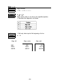
1
THERMAL LINE PRINTER
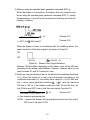
TM-T60/T60P
TM-T80/T80P
Operator’s Manual
400206500
All rights reserved. No part of this publication may be reproduced, stored in a retrieval system, or transmitted in any form or by any means, mechanical, photocopying, recording, or otherwise. without the
prior written permission of Seiko Epson Corporation. No patent liability is assumed with respect to the
use of the information contained herein. While every precaution has been taken in the preparation of this
book, Seiko Epson Corporation assumes no responsibility for errors or omissions. Neither is any liability
assumed for damages resulting form the use of the information contained herein.
Neither Seiko Epson Corporation nor its affiliates shall be liable to the purchaser of this product or third
parties for damages, losses, costs, or expenses incurred by purchaser or third parties as a result of; accident. misuse, or abuse of this product or modifications, repairs, or alterations to this product, or (excluding the U . S .) failure to strictly comply with Seiko Epson Corporation’s operating and maintenance instructions.
Seiko Epson Corporation shall not be liable, against any damages or problems arising from the use of any
options or any consumable products other than those designated as Original Epson Products or Epson
Approved Products by Seiko Epson Corporation.
Epson and ESC/POSTM are registered trademarks of Seiko Epson Corporation.
NOTICE:
The contents of this manual are subject to change without notice.
Copyright © 1993 by Seiko Epson Corporation, Nagano, Japan
FCC-CLASS A
FCC COMPLIANCE STATEMENT FOR AMERICAN USERS
This equipment has been tested and found to comply with the limits for a Class A
digital device, pursuant to Part 15 of the FCC Rules. These limits are designed to
provide reasonable protection against harmful interference when the equipment is
operated in a commercial environment.
This equipment generates, uses, and can radiate radio frequency energy and,
if not installed and used in accordance with the instruction manual, may cause
harmful interference to radio communications. Operation of this equipment in a
residential area is likely to cause harmful interference in which case the user will
be required to correct the interference at his own expense.
WARNING
The connection of a non-shielded printer interface cable to this printer will invalidate the FCC Certification of this device and may cause interference levels which
exceed the limits established by the FCC for this equipment. You are cautioned
that changes or modifications not expressly approved by the party responsible for
compliance could void your authority to operate the equipment.
FOR CANADIAN USERS
This digital apparatus does not exceed the Class A limits for radio noise emissions
from digital apparatus as set out in the radio interference regulations of the Canadian Department of Communications.
Le pésent appareil numérique n’émet pas de bruits radioélectriques dépassant les
limites applicables aux appareils numériques de Classe A prescrites dans le
réglement sur le brouillage radioélectriques édicte par le Ministére des Communications du Canada.
- i -
INTRODUCTION
The TM-T6O/T6OP and the TM-T8O/T8OP are a one-station printer for ECR
and POS use which can be used for printing the results of scaling or
measuring.
The main features are as follows:
. Light and ultracompact
. High-speed printing
. low-noise thermal printing
. High reliability due to a low number of moving parts
. Maintenance such as head cleaning performed easily
Command protocol based on ESC/POSTM, a widely used standard
. Four-way routing of the interface cable, drawer control cable, and
power cable on either side, underneath, or out the back of the case
. Easy access to the power switch on the front of the printer body;
access to both sides and the back not necessary
. Bar code printing possible using a bar code command
. 90’ character rotation possible
. Repeated operation and copy printing possible through macro definition
. Drawer control possible using the drawer-kick interface
l
I
Interface
TM-T60
Serial
TM-T6OP
Parallel
Serial
Parallel
TM-T80
TM-T8OP
Paper Width
60mm
8Omm
Please be sure to read the instructions in this manual carefully before using your
new Epson printer.
The TM-T60 and the TM-T80 have a serial interface connector and the TMT6OP and TM-T8OP have a parallel interface one.
Except for the defferent roll width accommodated by the two printers, the
functions provided by the TM-T6O/T60P and the TM-T8O/T8OP are the same.
Most of the illustrations used in this operation manual show the TM-T6O/T6OP.
- i i -
About this manual
I . SETTING UP]
* Chapter 1 contains information on unpacking the printer, choosing the
place for the printer, and names and functions of parts.
* Chapter 2 and Chapter 3 contain information on connecting and setting
up the printer.
* Chapter 4 contains information on testing the printer.
II . REFERENCE1
* Chapter 5 contains information on using the printer.
* Chapter 6 contains information on software control including printer
command descriptions.
APPENDIX
Appendixes contain information on general specifications, character code
tables and a list of commands.
CONTENTS
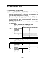
I . SETTlNG UP
Chapter 1 Unpacking the Printer
l - l Checking the Contents of the Box . . . . . . . . . . . . . . . . . . . . . . . . . . . . . . . . . . . . . . . .
l - 2 Choosing a Place for the Printer . . . . . . . . . . . . . . . . . . . . . . . . . . . . . . . . . . . . . . . . . . . . .
l-3 Removing the Protective Material . . . . . . . . . . . . . . . . . . . . . . . . . . . . . . . . . . . . . . . . . . . . .
l - 4 Names and Functions of Parts . . . . . . . . . . . . . . . . . . . . . . . . . . . . .................
Chapter 2 Before Setting Up
Connecting the Power Supply to the Printer . . . . . . . . . . . . . . . . . . . . . . . . . . . . .
2 - 2 Connecting the Host Computer to the Printer . . . . . . . . . . . . . . . . . . . . . . . . . . .
2- 1
Chapter 3 Installing the Parts
2
2
3
3
4
6
6
7
9
3 - 1 Installing the Roll Paper . . . . . . . . . . . . . . . . . . . . . . . . . . . . . . . . . . . . . . . . . . . . . . . . . . . . . . . . 9
3-2 Adjusting the Paper-End Detector . . . . . . . . . . . . . . . . . . . . . . . . . . . . . . . . . . . . . . . . . . 12
3 -3 Setting the DIP Switches . . . . . . . . . . . . . . . . . . . . . . . . . . . . . . . . . . . . . . . . . . . . . . . . . . . . . 14
17
Chapter 4 The Self Test
4 - 1 The Open-Cover Detector . . . . . . . . . . . . . . . . . . . . . . . . . . . . . . . . . . . . . . . . . . . . . . . I . . . . . . 17
4 - 2 Checking Operation with the Setf Test . . . . . . . . . . . . . . . . . . . . . . . . . . . . . . . . . . . . 18
...
--Ill-
II. REFERENCE1
Chapter 5 Cautions while Using the Printer
Panel Switches and Commands .............................................
5 - 2 Printable Area .....................................................................
5 - 3 Miscellaneous Notes ............................................................
5-4 Error Correction ..................................................................
5-5 Cleaning the Head ...............................................................
5 - l
20
20
21
22
25
27
28
Chapter 6 Software Control
.....................................................................
28
6 - 1 Printer Control
6 - 2 Command Descriptions ......................................................... 29
30
6-3 Commands ........................................................................
52
6 -4 Program Descriptions .........................................................
59
APPENDIX
APPENDIX A General Specifications ............................................. 59
63
APPENDIX B Connectors ............................................................
............................................................ 66
APPENDIX C Interfaces
APPENDIX D Notes on Using the Drawer kick-out Connector ------------ 71
.......................................... 74
APPENDIX E Character Code Tables
APPENDIX F Command Summary ................................................ 77
- i v -
I. SETTING UP
Chapter 1 Unpacking the Printer
1-1
n
Checking the Contents of the Box
Checking the parts
Remove the printer and other parts from the box.
l
l
Roll paper
l
Operator’s Manual
Printer
Make sure no parts are missing or damaged.
If you find any damaged or missing parts, please contact your dealer for
assistance.
H Maintenance
Keep the packing case and packing materials in case you ever need to
transport or store your printer.
n
Optional parts
Power supply (PS-130)) Power supply DC cable (1.5m)
-2-
1 - 2 Choosing a Place for the Printer
n
n
n
n
n
Avoid locations that are subject to direct sunlight or excessive heat
(near heaters).
Avoid using or storing the printer in places subject to excessive temperatures or moisture.
Do not use or store the printer in a dusty or dirty location.
When setting up the printer, choose a stable, horizontal location.
Intense vibration or shock may damage the printer.
Ensure the printer has enough space to be used easily.
1-3 Removing the Protective Material
An orange plastic spacer is put into the printing mechanism section to
protect the printer from damage during transportation. Before you turn on
the printer, be sure to remove the spacer according to the following steps.
1. Open the printer cover.
2. Raise the head-open lever to remove the spacer.
3. Store it in the hollow space. Re-insert the space when transporting.
4. Lower the head-open lever.
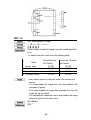
1 - 4 Names and Functions of Parts
n Part names
Printer cover
Operation panel
Power connector
Interface connector
Drawer-kick connector
DIP switches (*1)
TM-T60/T80
TM-T60P/T8OP
* 1: The DIP switches are located behind the small cover on the bottom
of the printer.
-4-
Operation panel
Panel switches
POWER
Press the POWER button to turn the printer ON and OFF. When
the button is pushed down, the power is on. When pressed again,
the button returns to its original position, turning the power off.
Do not turn the power off during printing.
l
PAPER FEED
l
Press the PAPER FEED button to feed roll paper.
You cannot feed paper when the printer cover is open.
Panel lights (LED)
POWER (green)
The POWER light is on when power is turned on.
ERROR (red)
The ERROR light is on when the printer cover is not closed completely, or when the paper roll is near the end. The light blinks during an
error condition, or when waiting for data during macro execution.
PAPER (red)
The PAPER light is on when roll paper is not loaded, or when the
paper roll is near the end.
-5-
Chapter 2 Before Setting Up
2- 1 Connecting the Power Supply to the Printer
n
Plugging in AC adapter
The printer must be connected to an external power supply.
Be sure to use a power cable that matches the specifications of both
the printer and the power supply unit.
--------------------------------------------------------------------CAUTIONS:
Before connecting the printer to the power supply, make sure
that the voltage (24 VDC) and power specifications match the
printer’s requirements.
Using an incorrect power supply can cause serious damage to
II the printer.
II
I
l
I
l
II
Connect the power unit according to the following procedure.
Make sure the printer and the power unit are turned off.
Plug the power cable’s connector into the printer’s power connector
with the arrow mark facing downward.
Plug the power cord into the outlet, and turn on the power unit.
TM-T60/T80
-6-
2-2 Connecting the Host Computer to the Printer
n
Connecting the interface cable
Connect the printer to a host ECR (host computer) using an interface
cable matching the specifications of the printer and the host ECR
(host computer).
TM-T6O/T80
Connect the interface cable according to the following procedure.
Turn off the printer, power unit, and host computer.
Plug the interface cable connector into the interface connector on the
printer; then insert a screwdriver between the rear rubber feet and fasten
the screws on both sides of the connector.
Plug the drawer-kick cable connector into the drawer-kick connector on the
printer (if this connector is covered, you cannot attach a drawer-kick cable
to your printer).
Remove the drawer-kick cable by pressing in on the connector’s clip and
pulling out.
l
-7-
TM-T60P/T80P
Connect the interface cable according to the following procedure.
Turn off the printer, power unit, and host computer.
Plug the interface cable connector into the interface connector on
the printer.
Squeeze the wire clips together until they lock in place on both
sides of the connector.
Attack the ground wire to the ground connector on the right side of
the interface connector.
Plug the drawer-kick cable connector into the drawer-kick connector
on the printer (if this connector is covered, you cannot attach a
drawer-kick cable to your printer).
-6-
Chapter 3 Installing the Parts
3-l Installing the Roll Paper
Installing the roll paper
Be sure to use roll paper that matches the printers specifications.
Using scissors, cut the leading edge of the roll paper perpendicular
to the paper feed direction.
Open the printer cover and raise the release-lever toward you.
Release
lever
Load the roll paper while Iightiy pressing the right roll paper holder
outward. Release the holder after fitting the paper core onto
the holder. Make sure the roll paper turns freely.
When loading roll paper, make sure to insert so that it rotates in
the correct direction.
Correct
Incorrect
Roll paper
holder
- 9 -
Chapter 3 Installing the Parts
3-l Installing the Roll Paper
Installing the roll paper
Be sure to use roll paper that matches the printers specifications.
Using scissors, cut the leading edge of the roll paper perpendicular
to the paper feed direction.
Open the printer cover and raise the release-lever toward you.
Release
lever
Load the roll paper while Iightly pressing the right roll paper holder
outward. Release the holder after fitting the paper core onto
the holder. Make sure the roll paper turns freely.
When loading roll paper, make sure to insert so that it rotates in
the correct direction.
Correct
Incorrect
Roll paper
holder
- 9 -
Insert the edge of the roll paper into the paper slot and turn the
paper-feed knob in the direction of the arrow to feed the paper 5
cm beyond the tear-off edge.
Don’t turn the paper-feed knob when the release lever is down.
l
Paper-feed knob
Raise the head-open lever, unroll the paper a little and pull lightly
from the roll paper side to eliminate twist or misalignment.
Retighten the roll paper to remove any slack. Roth edges of the
paper should be aligned parallel to the paper roll.
Push down the release lever and then the head-open lever. Tear
off any extra paper at the tear-off edge by pulling the paper toward
you.
Close the
-IO-
n
Removing jammed paper
Removing jammed paper according to the following steps.
Open the printer cover and raise the head-open lever.
r
I
_ _ _ - - - _ _ _ - - _ _ _ - - - - - - - - - - - - - - - - - - - - - - - - - - - - - - - - - - - - - - - - - - - - - - - - - - - - - - - - - - - - .
CAUTION:
* The print head is very hot immediately after printing.
Always remove jammed paper after the print head has cooled.
I
I
I
I
Head-open lever
r
Remove any jammed paper.
--------------------------------------------------------------------------CAUTION:
. Never touch the print head.
I- - - - - - - - - - - - - - - - - - - - - - - - - - - - - - - - - - - - - - - - - - - - - - - - - - - - - - - - - - - - - - - - - - - - - - - - - - - -
II
II
II
I
Push the head-open lever down. Reload roll paper and close the
printer cover. See 3-l
-11-
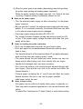
3 -2 Adjusting the Paper-End Detector
n
The paper-end detector
The paper-end detector senses when the paper is nearing its end and
turns on the PAPER lamp.
The paper-end detector can be adjusted according the thickness of the
Paper.
n
How to adjust the paper-end detector
Roll paper may differ in spool size, so it may be necessary to adjust
the paper-end detector.
Use the specified paper roll with a cure inside diameter (d1) of 12mm
and an outside diameter (d2) of 18 mm.
The thickness of the spool can vary; use the table to determine
the paper-end detector adjustment.
Table 3-l. Adjustment Values of the Paper-end Detector
Adjustment Value Dimension of T (mm)
Approx. 0
#l
---------------------------------------------Approx. 2
#2
.--------------------------------------------Approx. 4
#3
--------------------------------------------Approx. 6
#4
---------------------------------------------Approx. 8
#5
---------------------------------------------#6
Approx . 10
d2
-12-
Loosen the adjusting screw that holds the paper-end detector.
Then set the top of the positioning plate to the appropriate adjustment
position, and tighten the adjusting screw.
NOTES:
1 . The T dimensions corresponding to the adjustment values in
II
the table are caluculated from standard measurements; some
II
variations in the actual mechanism.
I
2. After adjusting, ensure that the detector operates smoothly.
L- - - - - - _ - - - _ _ _ _ - - - - - - - - - - - - - - - - - - - - - - - - - - - - - - - - - - - - - - - - - - - - - - - - - - - - - - - - - - -
-13-
i
I
I
J
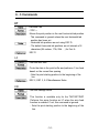
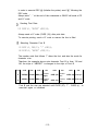
3 -3 Setting the DIP Switches
n
Locating the DIP switches
On the underside of your printer are a number of DIP switches that can be set
to perform a number of different functions.
- You can change the function of your printer by turning DIP switches
on or off.
- Current DIP-switch settings are printed out during the self test.
- The switches numbered from left to right are SW1-1 through SW1-10
(TM-T6O/T80) or SW1-1 through SW1-5 (TM-T6O/T80P).
- Each switch functions as described in the lists on the following page.
n
Setting the DIP switches
Follow these steps when changing DIP-switch settings.
ΠTurn the printer power supply off.
• Remove the small cover on the printer’s bottom to expose the DIP
switches.
Flip the DIP switches using tweezers or other narrow-ended tool.
Ž Switches in the up position are ON; those in the down position are
OFF.
TM-T6O/T8O
TM-T6()p/T8oP
r - - - - - - - - - - - - - - - - - - - - - - - - - - - - - - - - - - - - - - - - - - - - - - - - - - - - - - - - - - - - - - - - - - - - - - - - - - -
I
NOTE:
- Changes made with the power on have no effect until the power
I
I
supply is turned off and then on again.
I
I
- - - - - - - - - - - - - - - - - - - - - - - - - - - - - - - - - - - - - - - - - - - - - - - - - - - - - - - - - - - - - - - - - - - - -
-14-
I
I
I
I
I
I
I
- - - - - - -
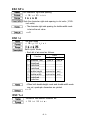
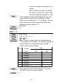
n
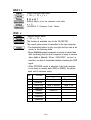
TM-T60/T60 DIP-Switch Functions
Table 3-2 DIP-Switch Functions (On the bottom of the case)
DIP SW1
SW- 1
ON
OFF
Ignores data reception errors
Prints “?” for data reception
errors
- - - - - - - - - - - - - - - - - - ---------------------.----------------------------------45 bytes
Data buffer 4 Kbytes
-SW-2
- - - - -Data
- - - -buffer
- - - - --------------------------------------------------------control
DTR/DSR control
-SW3
- - - -XON/XOFF
- - - - - - - --------------------------------------------------------SW-4 Parity
No Parity
-----------------------------------------------------------------------------Odd parity
SW-5 Even parity---------------------------------------------------------------------------SW-6
Change baud rate (Refer to Table 3-3)
SW-7
SW-8
SW-9
Change print density (Refer to Table 3-4)
w-10
Normally OFF
Table 3-3. Baud Rate Selection
Baud Rate SWl - 6 SW1 - 7
1200 bps
O N
O N
4800
OFF
O N
9600
19200
O N
OFF
OFF
OFF
Table 3-4. Print Density Selection
Print Density
LIGHT
DARK
SW1
ON
-8 SW1
-9
Level
1
OFF
OFF
2
--------------------------------------ON
OFF
3
--------------------------------------4
OFF
ON
-15-
ON
n
TM-T60P/T80P DIP-Switch Functions
Table 3-5. DIP-Switch Functions (On the bottom of the case)
DIP SW1
OFF
ON
SW-l Auto-feed function is always
Depends on AUTO FEED XT
valid
signal
-------------------------------------------------------------------------------------------SW-Z Data buffer 0 byte
Data buffer 4 Kbytes
------------------------------------------------------------------------SW-3
Character print density (Refer to Table 3-6)
SW-4
----------------------------------------------------------------------------SW-5
Normally OFF
Table 3-6. Print Density Selection
Print Density
LIGHT
DARK
SW1-3
ON
SW1-4
Level
O N
1
OFF
OFF
2
ON
OFF
ON
3
OFF
- 16-
4
Chapter 4 The Self Test
4 - 1 The Open-Cover Detector
n
The open-cover detector
This unit has an open-cover detector located inside the printer cover.
- Data is not printed when the printer cover is open.
- Opening the cover sets the printer OFF LINE; data cannot be received
when the printer is OFF LINE.
- Paper cannot be fed with the paper-feed switch when the printer cover
is open.
n
Returning the printer ON LINE
- Closing the cover sets the printer ON LINE automatically.
----------------------------------------- - - - - - - - - - - - - - - - - - - - - - - - - - - - I
II
II
CAUTION:
I
I
The printer cover cannot be closed unless the head-release lever
I
I
I
I
I
and
the
head-open
lever
are
down.
I
I. - - - - - - - - - - - - - - - - - - - - - - - - - - - - - - - - - - - - - - - - - - - - - - - - - - - - - - - - - - - - - - - - - -
- 17-
-
-
-
4 -2 Checking Operation with the Self Test
n
The purpose of the self test
The self test checks whether the printer has any problems. When the
printer does not function properly, please contact the dealer.
n
The self test checks the following
- Control circuit functions
- Printer mechanism
- Print quality
n
- Control ROM version
. RAM checking
- DIP-switch settings
Run the self test according to the following procedure
ΠMake sure the printer cover is closed and the roll paper is installed
correctly.
• While holding down the PAPER FEED switch, press on the POWER
button. The test starts.
Ž If you wish to stop the test before it has finished, press the PAPER
FEED button. To restart, press the PAPER FEED button again.
The self test finishes automatically when the printer has printed out
the specified numbers of lines.
• Turn the POWER button off.
The information printed out during the self test is as follows.
TM-T6OP/T8OP
TM-T6O/T-80
ROM version
Interface type
* Data buffer capacity
* Print density
DIP-switch settings
Self test print pattern
l
l
l
l
- 18-
II. REFERENCE
Chapter 5 Cautions while Using the Printer
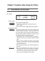
5-l
Panel Switches and Commands
n switches
J
(1) Power switch
Function
t
I
I Note
Turns the power supply on/off.
The RAM is initialized after turning off the circuit
power supply.
Don’t touch the power supply switch during printing.
(2) Paper-Feed switch
Function If this switch is pressed, paper is fed one line based on the
currently specified line spacing. If this switch is held for 200
ms or more, paper is fed as long as the switch is pressed,
and stops when the switch is released. If line spacing is set
to 0, paper is fed while the switch is pressed.
The defined macro is executed when the switch is
pressed during the macro executing command standby
state.
Paper is fed by operating this switch, except during
printing, an error state, and the macro executing
command standby state.
Paper feeding is performed even during the paper nearend state.
N o t e
Paper cannot be fed when the printer cover is open.
* The paper-feed switch can be enabled or disabled
with the ESC c5 command. When this switch is disabled, you cannot feed paper with the switch.
l
l
l
l
l
l
-
2
o
-
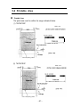
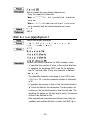
5-2 Printable Area
n
Printable Area
The print area must be within the range indicated below.
(1) TM-T6O/T6OP
Units: mm
Print head printing position
(2) TM-T8O/T8OP
Units: mm
Print head printing position
-21-
5 -3 Miscellaneous Notes
n
Notes on printing and paper feeding
(1) Because the TM-T60/T8OP and TM-T8O/T8OP are a line printer, they
automatically feed paper after printing the data.
When the line spacing is set to a small value, the paper may be fed
mare than the set amount to print all the data.
For example, when the line spacing is set to 10 dots (10/l80 inch),
the printer normally feeds just 10 dots for a carriage return; however,
the printer feeds the paper 24 dots when printing normal Font A
characters. (Refer to Table 5-l)
When all the characters on one line are rotated, refer to Table 5-2
for paper feeding.
Table 51. Required Paper Feed Amount Dots
(When the line spacing is set to 10 dots)
Required Paper Feed Amount (dots)
Font A
Font
B
Normal characters
24
Doubleheight
48
--------------------------------------24
Double-width
--------------------------------------Quadruple
48
Normal characters
17
--------------------- ---------------------------------------Double-height
34
--------------------------------------- - - - - - - - - - - - - - - - - 17
------------------34
24
Table 5-2. Required Paper Feed Amount Dots
(When all the characters on one line are rotated)
Required Paper Feed Amount (dots)
Font A
Font B
Normal characters
12
--------------_----------------------------------------------Double-height
24
1- Double-width
12
I
- - - - - - - - - - - - - - - - - - - - - - - - - - - - - - - - - - ^ - - - - - - - - - - - - - - - - - - - - - Quadruple
t
24
I
Normal characters
9
-------------------------------------------------Double-height
18
Double-width
9
Quadruple
18
-22-
(2) When the printer goes to the standby (data-waiting) state during printing,
the printer stops printing and feeding paper temporarily.
When the printer restarts, the paper may shift 1 to 3 dots at the start
of printing. Graphics printing is particularly affected by this.
n
Notes on the power supply
• Turn the external power supply on after connecting it to the power
supply connector.
• Be sure you don’t connect the external power supply with the wrong
polarity. If it is connected incorrectly, the internal circuit fuse may blow
or the external power supply may be damaged.
• The power supply voltage should be 24 VDC ±7%.
The voltage fluctuation between no-load and printing should be ±2%
or less. If the power supply voltage flucuates more than this, print
quality will be poor.
n
Notes on handling the printer mechanism
• Don’t turn the paper-feed knob while the print head is down.
• Don’t pull paper out (forward/backward directions) while the print
head is down.
• The thermal elements of the head and driver IC are easily damaged;
avoid touching them with anything made If metal.
• The areas around the print head and motor surface are very hot
during and just after printing; don’t touch directly with your fingers.
• Operate the head-open lever only when necessary.
• Don’t touch the surface of the head’s thermal elements directly with
your fingers. (Dust and dirt can stick to the surface and affect the
thermal elements .)
• Thermal paper containing Na-, K–, and Cl- ions will affect the head’s
thermal elements. Be sure to use only the paper specified.
• Label paper cannot be used.
n
Notes on paper cutting
Roll paper may be pulled out slightly when paper is manually cut.
Dots may have a squeezed appearance in the vertical direction after
cutting.
To prevent this, feed paper for 12 steps (6 dots) or more before printing.
-23-
n
Handling thermal paper
(1) Notes on using thermal paper
Chemicals and oil that come into contact with the thermal paper may
cause paper discoloration, and can also cause the ‘printing to fade.
Therefore, pay attention to the following:
a) Use water-based paste, starch paste, polyvinyl paste, or MC
paste when gluing thermal paper.
b) Volatile organic solvents such as alcohol, ester, and ketone can
cause discoloration.
c) Some adhesive tapes may cause discoloration, and may also
cause the printed image to fade.
d) If thermal paper touches anything that contains phthalic acid ester
plasticizer for a long period, it can reduce the image formation
ability of the paper and can cause the printed image to fade.
When storing thermal paper in a card case or sample notebook,
be sure to use only products made from polyethylene, polypropylene,
or polyester.
e) If thermal paper touches copy paper immediately after copying,
the printed surface may discolor.
f) Thermal paper must not be stored with the printed surfaces
touching each other because the printing may be transferred
between the surfaces.
g) If the surface of thermal paper is scratched with a nail or other
hard metal object, it may discolor.
(2) Notes on thermal paper storage
Color development begins at 70°c , so the following precautions should
be taken.
a) Store paper away from high temperature and humidity. Don’t store
thermal paper near a heater or in direct sunlight.
b) Avoid direct light.
If exposed to direct light for a prolonged period, paper color may
change or printed images may fade.
-24-
5-4
n
Error Correction
ERROR LED (red)
Lights:
On when the printer cover is not closed completely, or when the
paper roll is near the end.
Blinking: Blinks during the error states shown in Table 5-3.
Blinks during the print-waiting state (macro executing command)
shown in Table 5-4.
Table 5-3. Error Display
Error
RAM check error
ON/OFF Timing Pattern
Recovery
Impossible to recover
15Oms
Transistor error
Impossible to recover
Power supply voltage,
Impossible to recover
(Power supply should be
high voltage error
inspected.)
Impossible to recover
(Power supply should be
Power supply voltage,
low voltage error
inspected.)
-25-
Table 5-3. Error Display (Continued)
Error
Print head thermistor
error
Internal data
processing error
150 ms
150 ms
Print head overheating
error
900 ms
300 ms
Impossible to recover
150 ms
150 ms
150 ms
Print head paper out
error
Recovery
ON/OFF Timing Pattern
Recovered by turning the
power off and on
1950 ms
150 ms
150 ms
--150 ms
150 ms
Recovered by closing the
cover after inserting paper
1650 ms
Recovers automatically
when the print head temperature drops back down
1350 mS
Table 54. Macro Executing Command Standby State Display
Error
Recovery
ON/OFF Timing Pattern
300 ms
Recovered after
executing the
Waiting for
macro execution
macro by pressing
the papaer-feed
300 ms
I
switch
The macro executing command can specify the number of executions of a
specified definition range. At that time, continuous execution of the macro or
execution of the macro with the paper-feed switch is selectable.
When executing the macro with the paper-feed switch, the error LED blinks to
indicate the print-waiting state.
-26-
5-5 Cleaning the Head
n
Cleaning the head
Cleaning the head according to the following procedure.
I
I
CAUTION:
Do not clean the head immediately after printing; the head may be
hot.
I
---------------------------------------------------------------------------ΠOpen the printer cover and raise the head-open lever.
If roll paper is loaded, remove it from the head area.
• Clean the heating element of the head with a cotton swab containing
an alcohol solvent (ethanol, methanol, or IPA).
( - - - - - - - - - - - - - - - - - - - - - - - - - - - - - - - - - - - - - - - - - - - - - - - - - - - - - - - - - - - - - - - - - - - - - - - - - - - - - ~
CAUTION:
Never touch the head; oils on your skin can damage the head.
- - - - - - - - - - - - - - - - - - - - - - - - - - - - - - - - - - - - - - - - - - - - - - - - - - - - - - - - - - - - - - - - - - - - - - - - - - - - - ~
Ž Push the head-open lever down. Reload roll paper and close the
printer cover. See 3-l.
Head
Element of the head
-27-
II
Chapter 6 Software Control
6 - 1 Printer Control
n
Controlling the printer with commands
The printer is controlled by “commands” that can change the size of the
characters, and perform other functions.
See APPENDIX E Character Code Tables and APPENDIX F command
Summary.
There are two types of commands.
ΠOne-byte commands
Horizontal tab
• LF
Print and line feed
•HT
• Several-byte commands
• ESC SP
l
n
ESC 3n
Set character right-side spacing
Set line spacing using minimum units
How to use this table
Horizontal by vertical hex
i.e. 4A = J
< >H denotes hexadecimal
< > denotes decimal numbers
(Refer to APPENDIX E)
Hexadecimal
-28-
Binary
Decimal Numbers
6 - 2 Command Descriptions
n
Command descriptions
*XXX
* N a m e
* F o r m a t
Command
The name of the command
The code sequence
In this description, < >H denotes hexadecimal
numbers, < > denotes decimal numbers and < >B
denotes binary numbers.
[ ]k indicates the contents of the [ ] should be
repeated times.
The allowable range for the arguments
Description of the command function
(Included only when necessary)
The default values for the commands
Related commands
Example of using the commands
k
*[Range
*[Description]
*[ Notes ]
*Default
* Reference
*Example
-29-
6 - 3 Commands
HT
Horizontal tab
< 09 > H
Moves the print position to the next horizontal tab position.
. This command is ignored unless the next horizontal tab
position has been set.
- Horizontal tab positions are set using ESC D.
- The default horizontal tab positions are at intervals of 8
characters (9th column, 17th, 25th. . .) for Font A.
ESC D
LF
Print and line feed
Prints the data in the print buffer and performs 1 line feed
based on the current line spacing.
- Sets the print starting position to the beginning of the
line.
ESC 2, ESC 3, 5-3 Miscellaneous Notes
CR
Print and carriage return
This function is available only for the TM-T60P/T80P
Performs the same function as LF when the auto feed
function is enabled. If not, this command is ignored.
- Sets the print starting position to the beginning of the
line.
-30-
ESC SP n
Set character right-side spacing
< 1B > H < 20 > H < n >
Sets the character right-side spacing in dot units ( l/180inch units).
• The character right-side spacing for double-width mode
is twice the set value.
n=O
ESC ! n
Set print mode
< 1B >H < 21 >H < n >
Sets a print mode.
• Each bit of n is used as follows:
Value
Bit
Function
1
0
Font A
Font B
0 Character font
----~-------------------------------..----------1
Undefined
-----------------------------------~----------2 Undefined
---------------------------------------------3 Undefined
---------------------------------------------4 Double-height
canceled set
---------------------------------------------5 Double-width
canceled set
---------------------------------------------6 Undefined
-----------------------------------..----------7 Underline
• When both double-height mode and double-width mode
are set, quadruple characters are printed.
n = O
ESC % n
Set/cancel user-defined character set
< 1B >H < 25 > H < n >
-31-
Sets or cancels the user-defined character set.
• Only the lowest bit of n is valid.
When n = < * * * * * * * 1 > B , the userdefined character
set is set.
W h e n n = < * * * * * * * O >B , the u s e r d e f i n e d c h a r a c t e r
set is canceled (and the internal character set is set).
n = 0
ESC &
ESC & s n m [a[p]sXa]m-n+1
Define user-defined characters
< 1 B >H < 2 6 >H < s > < n > < m > [ < a > < p 1 >
< p2 >---< psXa >] m-n+1
s=3
Defines user-defined characters for ANK character codes.
- “s” specifies the number of bytes in the vertical direction.
- “n” specifies the beginning ASCII code for the definition
and "m" the final code. If only one character is defined,
use
n = m.
- The allowable character code range is from ASCII code
< 2O >H to < 7E >H and the maximum number of characters
is 95.
“a” specifies the number of dots in the horizontal direction.
- “p” Is the dot data for the characters. The dot pattern for
a dots is in the horizontal direction from the left side. The
remaining dot pattern on the right side is space. The amount
of data to be defined is sXa.
- After userdefined characters are defined once, they are
available until another definition is made, until ESC @ is
l
-32-
executed, until GS * is executed, or until the printer is
turned off.
. The user-defined characters and a down-loaded bit image
cannot be defined at the same time. If this command
is executed, the down-loaded bit image will be cleared.
The same as the internal character set.
ESC %
- Font A is selected:
- Font B is selected:
-33-
ESC * m n1 n2 [d]k
Set bit image mode
< 1B >H < 2A >H < m >< n1 >< n2 >[< d >]k
k = n1 + 256 X n2 (m= 0, 1)
k = (n1 + 256 x n2) X 3 (m = 32, 33)
Sets the bit image mode using m and the number of dots
using n1 and n2.
Divide the number of dots to be printed by 256. The integer
answer is n2 and the remainder is n1. Therefore, the
number of dots in the horizontal direction is: n1+256Xn2.
. If the bit image data input exceeds the number of dots to
be printed on a line, the excess data is ignored.
. “d" indicates the bit image data. Set a corresponding bit to
1 to print a dot, otherwise set it to 0.
- The bit image modes selectable by m are as follows:
l
Vertical Direction
Horizontal Direction
m
Mode
Maximum
Dot
Number Dot
of Dots Density Density
Number of Dots
0 8-dot single-density
60 DPI 90 DPI
192
8
1
8-dot double-density 8
60 DPI 180 DPI
384
32 24-dot single-density 24
180 DPI
90 DPI
192
33 24-dot double-density 24
180 DPI 180 DPI
384
l
l
If m is out of range, n1 and the data following will be
processed as normal data.
After printing a bit image, the printer returns to the normal
data processing mode.
- 3 4 -
.
The relationship between the image data and dots to be
printed is as follows:
- 8-dot bit image
- 24-dot bit image
-35-
ESC 2
Set 1/6 inch line spacing
< 1B >H < 32 >H
Sets the line spacing to 1/6 of an inch.
ESC 3
n
Set line spacing using minimum units
< 1B >H < 33 >H < n >
Sets the line spacing to n/360 of an inch.
n = 60 (1/6 inch)
5-3 Miscellaneous Notes
ESC @
Initialize printer
< 1B >H < 40 >H
Clears the data in the print buffer and resets the printer
mode (to the same state as when the power is turned on).
- The DIP switches are not read again.
The data in the receive buffer is not cleared.
l
ESC D [n]k NUL
Set horizontal tab positions
< 1B >H < 44 >H [< n >]k < 00 >H
Sets horizontal tab positions.
- "n" specifies the column number from beginning of the line
for setting a horizontal tab position. [ n = (Column number)
- 1 ].
For example, when a tab is set is to be set at column 9,
n = 8.
- “k" indicates the total number of horizontal tab positions to
be set.
- 3 6 -
- A horizontal tab position is stored as the absolute value
of (character width X n) measured from the beginning of
the line. The character width includes the character rightside spacing, and double-width characters should be set
with twice the width of normal characters.
- Up to 32 tab positions can be set. Data which exceeds
32 tab positions will be ignored.
- Set <n>k in ascending order and place a NUL code <00>H
at the end.
- ESC D NUL clears all tabs. Any HT commands received
after clearing will be ignored.
- When a data value <n>k is less than or equal to the preceding
value <n>k - 1, the setting is considered to be finished.
In this case, the following data is processed as normal data.
- When a data value <n>k exceeds the number of
character printable on one line, set [(column number) =
(the number of maximum printable columns) + 1].
- Horizontal tab positions remain unchanged if the character
widths are changed after setting the horizontal tab positions.
- The default tab positions are at intervals of 8 characters
(9th column, 17th, 25th,---) for Font A.
ESC J n
Print and feed paper using minimum units
< 1B >H < 4A >H < n >
Prints the data in the print buffer and feeds the paper n/360
inches.
- The predetermined line spacing remains unchanged.
- Sets the print starting position to the beginning of the line.
- Not defined.
5-3 Miscellaneous Notes
-37-
ESC R n
Select international character set
n selects an international character set from the following table.
n
0
1
2
3
4
5
Country
U.S.A.
France
Germany
U.K.
Denmark I
Sweden
Country
n
6
7
8
9
10
Italy
Spain
Japan
Norway
Denmark II
n = 0
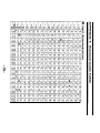
APPENDIX E Character Code Tables
ESC c3 n
Select paper detectors to output signals
< 1B >H < 63 >H < 33 >H < n >
This function is available only for the TM-T60P/T80P.
Select the paper detectors to output signals on the “paperend status line”.
- Each bit of n is used as follows.
Bit
Function
0
Journal near-end
1
Undefined
Undefined
2
3
4
Undefined
Undefined
5
Undefined
6
7
Undefined
Undefined
-38-
Value
0
1
Invalid
Valid
- In the TM-T60P/T80P, only the journal near-end detector
can be detected and only the lowest of n is valid.
n = 1
ESC c4 n
Select paper detectors to stop printing
< 1B >H < 63 >H < 34 >H < n>
Selects the paper detectors used to stop printing.
- Each bit of n is used as follows:
Bit
Function
0
Journal near-end
1
2
3
4
5
6
7
Undefined
Undefined
Undefined
Undefined
Undefined
Undefined
Undefined
Value
0
1
Invalid
Valid
- In the TM-T60P/T80P, only the journal near-end detector
can be selected and only the lowest bit of n is valid.
- When a paper-end is detected by the journal detector,
the printer goes OFF-LINE after printing stops.
n = 0
ESC c5
ESC c5 n
Enable/disable panel switches
< 1B >H < 63 >H < 35 >H < n >
Enables or disables all the paper feed switch.
- Only the lowest bit of n is valid.
-39-
When n = < * * * * * * * 0 > 8 , the paper feed switch is
enabled.
When n = < * * * * * * * 1 > 8 , the paper feed switch is
disabled.
- If the panel switches are disabled by this command, the
paper feed switch is disabled. Therefore, paper cannot be
fed with the paper feed switch.
n = 0
ESC d n
Print and feed paper n lines
< 1B >H < 64 >H < n >
Prints the data in the print buffer and performs n line feeds.
- Sets the print starting position to the beginning of the line.
- The predetermined line spacing remains unchanged.
Not defined.
5-3 Miscellaneous Notes
ESC p m n1 n2
Generate pulse
< 1B >H < 70 >H < m >< n1 >< n2 >
m = 0
The pulse defined by n1 and n2 is output on connector
pin m .
- m is specified as follows:
m
Connector Pin
0
Drawer kick out Pin 2
1
Drawer kick out Pin 5
ON time is n1X2 msec, and OFF time is n2X2 msec.
l If m is out of range, the printer reads n1 and n2 but does
not output a pulse.
l
-40-
ESC t n
Select character code table
< 1B >H < 74 >H < n >
Selects page n from the character code table.
n = 0
APPENDIX E Character Code Tables
ESC v
Transmit printer status
< 1B >H < 76 >H
This function is available only for the TM-T60/T80.
The current printer status is transmitted to the host computer.
- The transmitted status is only one byte and the data is as
shown in the following table.
. When DTR/DSR control is selected, one byte is transmitted
after confirming that the host computer is ready to receive
data (DSR is SPACE). When XON/XOFF control is
selected, one byte is transmitted without checking the DSR
signal.
- When DTR/DSR control is selected, if the host computer
is not ready to receive data (DSR is MARK), the printer
waits until it becomes ready.
Bit
0
1
2
3
4
5
6
7
Value
Function
Journal near-end
Undefined
Journal end
Undefined
Unused
Undefined
Undefined
Undefined
0
Paper is present
1
Paper is out
Paper is present
Paper is out
-41-
Fixed to 0
ESC u n
Transmit peripheral device status
< 1B >H < 75 >H < n >
n = 0
This function is available only for the TM-T60/T80.
Transmits the status current of connector pin 3.
- n is specified as follows:
n
Connector Pin
0
Drawer-kick connector Pin 3
. The transmitted status is only one byte and the data is as
shown in the following table.
- lf nothing is connected, bit 0 of n is always "1".
. When DTR/DSR control is selected, one byte is transmitted
after confirming that the host computer is ready to receive
data (DSR signal is SPACE). When XON/XOFF control is
selected, one byte is transmitted without checking the DSR
signal.
- When DTR/DSR control is selected, if the host computer
is not ready to receive data (DSR is MARK), the printer
waits until it becomes ready.
Value
Bit
Function
1
0
0
Pin 3 level
“HIGH”
“LOW”
1
Undefined
2
Undefined
3
Undefined
4
Unused
Fixed to 0
5
6
Undefined
Undefined
7
Undefined
Not defined.
ESC { n
Set/cancel upside-down character printing
< 1B >H < 7B >H < n >
-42-
Sets or cancels upside-down character printing.
- Only the lowest bit of n is valid.
When n = <*******1> B , upside-down character
printing is set.
When n = <*******0> B , upside-down character
printing is canceled.
- The upside-down character specification rotates normal
characters on the line by 180° and prints them.
- Valid only when input at the beginning of a line.
n = 0
When upside-down character printing is canceled.
When upsidedown character printing is set.
ABCDEFG
0123456
Paper feed direction
ESC V n
Set/channel 90° cw(clockwise) rotated characters
< 1B >H < 56 >H < n >
Sets or cancels the 90° cw rotation of characters.
- When n = 1, 90° cw rotated characters are set.
- When n = 0, 90° cw rotated characters are canceled.
ESC $ n1 n2
Set absolute position
< 1B >H < 24 >H < n1 >< n2 >
-43-
Sets the print starting position to the specified number of
dots (1/180 inch units) from the beginning of the line.
- Divide the number of dots by 256. The integer answer is
n2 and the remainder is n1. Therefore, the print starting
position becomes n1+n2X256 from the beginning of the
line.
- Any specification that exceeds the end of the line is ignored.
Not defined.
ESC ¥
ESC ¥ n1 n2
Set relative position
< 1B >H < 5C >H < n1 >< n2 >
Moves the print starting position to the specified number of
dots (1/180 inch units) from the current position.
- A positive number specifies movement to the right, and a
negative number specifies movement to the left.
- Negative numbers are specified using the supplement of N;
- N = 65536 - N
- Divide the number of dots by 256. The integer answer is
n2 and the remainder is n1.
- Any specification exceeding the printable area will be ignored.
Not defined.
ESC $
GS k n [d]k NUL
Print bar code
< 1D >H < 6B >H < n >[< d >]k < 00 >H
Selects a bar code system and prints the bar code.
- Sets the print starting position to the beginning of the line.
- n selects the bar code system from the following table.
-44-
- “d” indicates the characters to be printed and “k" indicates
the number of characters to be printed.
n
0
1
2
3
4
5
6
Bar code system
UPC-A
IPC-E
JAN13(EAN)
JAN8(EAN)
CODE39
ITF
CODABAR
. When data is present in the print buffer, this command is
ignored.
- Performs the paper feeding required for printing the bar
code, regardless of the current line spacing.
. In each bar code system, if a character code “d" cannot be
printed, the printer prints the processed data and the
following data is treated as normal data.
When a bar code system with a fixed number of printing
characters is selected, the number of characters “k”
should be agreed with that number.
If the horizontal size exceeds one line, the excess data is not
printed.
l
l
n= 0
GS w n
Select horizontal size (magnification) of bar code.
< 1D >H < 77 >H < n >
Selects the horizontal size of the bar code.
n= 3
-45-
GS h n
Select height of bar code
< 1D >H < 68 >H < n >
Selects the height of the bar code.
- n specifies the number of dots in the vertical direction.
n = 162
GS H n
Select printing position of HRI characters
< 1D >H < 48 >H < n >
Selects the printing position of HRI characters when printing
abarcode.
- n selects the printing position from the following table.
Printing position
n
0 Not printed
1 Above the bar code
2 Below the bar code
3 Both above and below the bar code
- HRI means Human Readable Interpretation.
- HRI characters are printed using the font specified by GS f.
n=0
GS f
GS f n
Select font for HRI characters.
< 1D >H < 66 >H < n >
n = 0, 1
Selects a font for the HRI characters used when printing a
bar code.
- 4 6 -
- n selects the font from the following table.
n
Font
0
Font A
1
Font B
. HRI means Human Readable Interpretation.
- HRI characters are printed at the position specified by GS H.
n = 0
GS H
GS * n1 n2 [d]n1Xn2X8
Define down-loaded bit image
< 1D >H < 2A >H < n1 >< n2 >[< d >]n1Xn2X8
Defines a down-loaded bit image with the number of dots
specified by n1 and n2.
- The number of dots in the horizontal direction is n1X8,
and in the vertical direction is n2X8.
- “d" specifies the bit image data.
- After a down-loaded bit image is defined once, it is
available until another definition is made, until ESC @ is
executed, until ESC & is executed, or until the printer is
turned off.
- The relationship between the bit image data and the transmitted dots is as follows:
The user-defined characters and a down-loaded bit image
cannot be defined at the same time. If this command
is executed, the user-defined characters will be cleared.
l
GS /
- 4 7 -
GS / m
Print down-loaded bit image
< 1D >H < 2F >H < m >
Prints a down-loaded bit image using the mode specified
by m.
- m selects the print mode from the following table.
Vertical Direction
Dot Density
0 Normal mode
180 DPI
1 Double-width mode
180 DPI
2 Double-height mode
90 DPI
Mode
m
3
90 DPI
Quadruple mode
Horizontal Direction
Dot Density
180 DPI
90 DPI
180 DPI
90 DPI
If any data is present in the print buffer, this command is
ignored.
- If a down-loaded bit image has not been defined, this
command is ignored.
- lf the down-loaded bit image data exceeds one line, the
image will not be printed.
- The user-defined characters and a down-loaded bit image
cannot be defined at the same time.
l
Not defined.
GS *
- 4 8 -
GS :
Set starting/ending, position of macro definition
< 1D >H < 3A >H
Specifies the starting or ending position of the macro definition.
- If this command is received while defining the macro, it
ends the definition.
- If the macro range exceeds 2048 bytes, the excess data
is not defined.
- Even if the ESC @ command (initialize the printer) is
performed, the macro definition is not cleared. Therefore,
it possible to include ESC @ in the macro definition.
- Normal printing operation is possible while defining the
macro.
Macro is not defined.
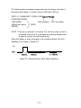
GS^
GS ^ n1 n2 n3
Execute macro
< 1D >H < 5E >H < n1 >< n2 >< n3 >
Executes a macro.
n1: Specifies the number of times to execute the macro.
n2: Specifies the waiting time for executing the macro.
n2 X 100 msec waiting time is required for one execution.
n3: Specifies the macro executing mode.
• n3 = 0
Continuous macro execution.
Executes n1 times continuosly at the
interval specified by n2.
• n3 = 1
Executes the macro with the paper feed
switch.
After waiting the period specified by n2,
the error LED blinks and the printer
-49-
waits for the paper feed switch to be
pressed.
After the paper feed switch is pressed,
the printer executes the macro once.
The printer repeats this operation n1 times.
• If this command is received while defining the macro, the
macro definition is aborted, and the definition is cleared.
• If the macro is not defined or if n1 is 0, nothing is executed.
• Paper cannot be fed with the paper feed switch while
executing the macro when n3 is 1.
Not defined.
GS :
ESC = n
Select device
< 1B >H < 3D >H < n >
0
n
255
Selects a device to receive data from the host computer.
- If the printer is not selected, the TM-T60P ignores all
received data until it is selected by this command.
- Each bit of n is used as follows:
Value
Bit
Function
1
0
I
0
Printetr
Invalid
Valid
1
Undefined
2
Undefined
3
Undefined
4
Undefined
5
Undefined
6
Undefined
7
Undefined
• Even when the printer is not selected, it may enter
the BUSY state due to printer operation.
n = 1
-50-
ESC a n
Name
Format
Range
Description
Align positions
< 1B >
0
n
H
< 61 >
H
< n >
2
Aligns all the data in one line to the specified position.
n specifies the alignment as follows:
•
Notes
Default
Example
Align left
ABC
ABCD
ABCDE
• Valid only when input at the beginning of a line.
n = 0
Align center
ABC
ABCD
ABCDE
-51-
Align right
ABC
ABCD
ABCDE
6 - 4 Program Descriptions
TM-T60/T80
1. Introduction
The TM-T6O/T80 is connected to the host computer by an RS-232C interface.
The TM-T60/T80 is easily controlled by sending data and commands from the
host computer.
The following examples use the main commands from MS-DOS BASIC.
2. Before Printing
Connect TM-T60/T80m to the host computer, power supply, and the drawer
while referring to Chapter 2.
Check that the RS-232C cable is connected properly, and the host
computer DIP-switches are set properly.
Check the TM-T60/T80 DIP-switches using the self test.
Connect the RS-232C cable to the host computer while referring to the
computer’s manual.
3. How to Write Program
Note: Omit step
and
if the drawer-kick connector is covered (the drawer
-kick function is not available).
For all programs, always first open device RS-232C.
100 OPEN "COM1:N81NN"
AS #1
Initialize the TM-T60/T80
110 PRINT #1,CHR$(27);"@';
“PRINT #1” is the order that sends data and commands through the
device. This device is opened in step
"CHR$(27)" is the ESC code.
-52-
In order to execute ESC @ (Initialize the printer) send “@" following the
ESC code.
Always write ” ; ” at the end of the commands or BASIC will send a CR
and LF code.
Sending Print Data
120 PRINT #1, “ABCDEF” ;CHR$(1O);
Always send a LF code (CHR$ (10)) after print data.
To execute printing, send a LF code or ensure the line is filled.
Selecting Character Font B
130 PRINT #1, CHR$(27); ”!” ;CHR$(1);
140 PRINT #1, “ABCDEF” ;CHR$(10);
The number code that follows “!” alters the font, and also the mode for
character size.
Therefore, the example above sets character Font B in lines 130 and
140; the style of “ABCDEF” is changed to the style of Font B.
Font
code
size
code
size
code
size
size
A
CHR$(0) Normal CHR$ (16)
Doubleheight
B
CHR$(1) Normal CHR$ (17)
DoubleDoubleCHR$ (49) Quadruple
CHR$ (33)
height
width
CHR$ (32)
Double-
code
width
CHR$ (48) Quadruple
Font B and the size are selected until CHR$ (27); “!” ; CHR$ (x) ; is
executed again or initialized.
-53-
Selecting character Font A and Double-width
150 PRINT #1, CHR$(27); ”!” ;CHR$(48);
160 PRINT #1, ”ABCDEFGHIJK” ;CHR$(10);
TM-T60
Font A (normal)
Font A (double-width)
: 32 characters per line.
: 16 characters per line.
Resetting the style to Normal.
170 PRINT #1, CHR$(27); ”!” ;CHR$(O);
180 PRINT #l, ”ABCDEFGHIJK” ;CHR$(10);
170 sets Font A to Normal. 180 sets the characters for printing.
Selecting the character code table
190
200
210
220
230
240
250
260
270
FOR I=240 TO 255
PRINT #1, CHR$(I);
NEXT I
’
PRINT #1, CHR$(27); ”t” ;CHR$(1);
’
FOR I=240 TO 255
PRINT #1, CHR$(I);
NEXT I
Page 0 characters, 190~210.
Page 1 characters, 250~270.
Refer to ESC t n.
-54-
Selecting international character codes
280 PRINT #1, CHR$(91);CHR$(92);CHR$(93);CHR$(94);CHR$(l0);
290 PRINT #1, CHR$(27); "R" ;CHR$(1);
300 PRINT #1, CHR$(91);CHR$(92);CHR$(93);CHR$(94);CHR$(l0);
280 prints 4 U. S. A characters. (default)
300 prints 4 French characters.
Refer to ESC R n
Resetting Printer functions
310 PRINT #1, CHR$(27); "@";
Initialize printer again.
Printing bar codes
320 PRINT #1, CHR$(29); "H" ;CHR$(2);
330 PRINT #1, CHR$(27);"$";CHR$(40);CHR$(O);
340 PRINT #1, CHR$(29);"k";CHR$(2);"012345678901";CHR$(0);
In order to print the bar code, you must send the GS code.
(Refer to Appendix E, GS code.)
“CHR$ (29)” is the GS code.
320 prints HRI (Human Readable Interpretation) as bar codes.
Refer to GS H n
330 sets the print starting position to the specified number of dots
( 40 ) . Refer to ESC $ n1 n2.
340 prints the bar code ; “k” executes printing. (Refer to GS k n [d]k
NUL.) "CHR$ (2)” selects the JAN 13 Bar code system.
The 12 characters, “012345678901” are print data.
A check-digit is added by the printer because 12 characters are sent,
and “012345678901” is printed.
“CHR$ (0)” must always be used as the last command
(representing end of data).
-55-
Using the drawer kick
350 PRINT #1, CHR$(27);"p";CHR$(O);CHR$(10);CHR$(100);
The “p” generates a specified pulse;
Refer to ESC p m n1 n2.
In line 350, the module terminal of the drawer kick outputs a 20-ms
pulse followed by a 200-ms wait.
How to read the status of the drawer kick
360
370
380
390
PRINT #1, CHR$(27);"u";CHR$(O);
A$=INPUT$(1, #1)
IF A$=CHR$(0) THEN PRINT "DRW:L"
IF A$=CHR$(1) THEN PRINT "DRW:H"
The “u” command in line 360 transmits the status of the drawer kick to
printer. Refer to ESC u n.
370 recieves the data from the printer through RS-232C.
380 and 390 display the status of the drawer kick on the CRT.
Close RS-232C
400 CLOSE #1
RS-232C must be closed by the computer using this command.
-56-
* * * * * * * *
Program List
********
in MS-DOS BASIC
HOST COMPUTER:EPSON PC-286
100 OPEN "COM1:N81NN" AS #1
110 PRINT #1,CHR$(27);"@";
120 PRINT #1,"ABCDEF";CHR$(10);
130 PRINT #1,CHR$(27);"!";CHR$(1);
140 PRINT #1,"ABCDEF";CHR$(10);
150 PRINT #1,CHR$(27);"!";CHR$(48);
160 PRINT #1,"ABCDEFGHIJK";CHR$(10);
170 PRINT #1,CHR$(27);"!";CHR$(O);
180 PRINT #1,"ABCDEFGHIJK";CHR$(10);
190 FOR I=240 TO 255
200
PRINT #1,CHR$(I);
210 NEXT I
220'
230 PRINT #1,CHR$(27);"t";CHR$(1);
240'
250 FOR I=240 TO 255
260
PRINT #1,CHR$(I);
270 NEXT I
280 PRINT #1,CHR$(91);CHR$(92);CHR$(93);CHR$(94);CHR$(10);
290 PRINT #1,CHR$(27);"R";CHR$(1);
300 PRINT X1,CHR$(91);CHR$(92);CHR$(93);CHR$(94);CHR$(10);
310 PRINT #1,CHR$(27);"@";
320 PRINT #1,CHR$(29);"Hn;CHR$(2);
330 PRINT #1,CHR$(27);"$";CHR$(40);CHR$(0);
340 PRINT #1,CHR$(29);"k";CHR$(2);"01234567890l";CHR$(O);
350 PRINT #1,CHR$(27);"p";CHR$(0);CHR$(10);CHR$(100;
360 PRINT #1,CHR$(27);"u";CHR$(0);
370 A$=INPUT$(1,#1)
380 IF A$=CHR$(0) THEN PRINT "DRW:L"
390 IF A$=CHR$(1) THEN PRINT "DRW:H"
400 CLOSE #1
-57-
n TM-T60P/T80P
Except for the different interface connectors accommodated by the two
types of the printer TM-T60/T80 and TM-T60/T80P, the description for the TM
-T60P/T80P printer is same with the TM-T60/T80’s which are mentioned be
fore.
However, omit step 12, because the TM-T60P/T80P can know the status of
the drawer-kick through pin 34 of the parallel interface connector.
* * * * * * * *
Program
List
********
in MS-DOS BASIC
HOST COMPUTER:EPSON PC-286
110 LPRINT CHR$(27);"@";
120 LPRINT "ABCDEF” ;CHR$(10);
130 LPRINT CHR$(27);’'!";CHR$(1);
140 LPRINT "ABCDEF";CHR$(10);
150 LPRINT CHR$(27);"!”;CHR$(48);
160 LPRINT "ABCDEFGHIJK";CHR$(10);
170 ‘LPRINT CHR$(27);"!";CHR$(0);
180 LPRINT "ABCDEFGHIJK";CHR$(10);
190 FOR I=240 TO 255
200 LPRINT CHR$(I);
210 NEXT I
220 ’
230 LPRINT CHR$(27);"t";CHR$(1);
240 ’
250 FOR I=240 TO 255
260 LPRINT CHR$(I);
270 NEXT I
280 LPRINT CHR$(91);CHR$(92);CHR$(93);CHR$(94);CHR$(l0);
290 LPRINT CHR$(27);"R";CHR$(1);
300 LPRINT CHR$(91);CHR$(92);CHR$(93);CHR$(94);CHR$(l0);
310 LPRINT CHR$(27);"@";
320 LPRINT CHR$(29);"H";CHR$(2);
330 LPRINT CHR$(27);“$";CHR$(40);CHR$(0);
340 LPRINT CHR$(29);"k";CHR$(2);‘012345678901"CHR$(0);
350 LPRINT CHR$(27);"p";CHR$(0);CHR$(10);CHR$(100);
-58-
APPENDIX
APPENDIX A General Specifications
1. Printing specifications
(1) Print method:
(2) Dot density:
(3) Printing direction:
Thermal line printing
180 dpi
Unidirectional with friction feed
(Manual reverse feeding is impossible)
(4) Print width
(TM-T60/T60P): 54mm, 384 dot positions
(TM-T80/T80P): 72mm,512 dot positions
(5) Characters per line(TM-T60/T60P): 32 (Font A)
: 42 (Font B)
(TM-T80/T80P): 42 (Font A)
: 56 (Font B)
(6) Character spacing:
0.28 mm (Font A)
0.28 mm (Font B)
Programmable by control command.
(7) Printing speed
(TM-T60/T60P): Approx. 12 lines/second (1/6 inch
feed)
: Approx. 18 lines/second (1/9 inch
feed)
: Approx . 2.0 inches/second
(TM-T80/T80P): Approx . 9 lines/second (1/6 inch
feed)
: Approx . 13 lines/second (1/9 inch
feed)
: Approx . 1.5 inches/second
: Printing speed may slow down depending on the data transmission
speed and combination of control
commands.
-59-
(8) Paper feeding speed
(TM-T60/T60P): Approx. 2.0 inches/second
(Approx. 50.0 mm/second)
(TM-T80/T80P): Approx. 1.5 inches/second
(Approx. 38.0 mm/second)
(9) Line spacing:
1/6 inch (4.23 mm) default
Programmable by control command.
(Minimum 1/360 inch)
2. Character specifications
95
128X2 pages
32
Alphanumeric:
Enlarged graphics:
International:
(1) Character sets:
(2) Character structure:
(3) Character size:
Font A: 12X24 (includes the horizontal
2-dot space)
Font B: 9X17 (includes the horizon’:“
2-dot space)
Default: Font A
1.41 mm (W)X3.39 mm (H) (Font A)
0.99 mm (VV)X2.40 mm (H) (Font B)
Table A.1 Character Sizes
Standard
Double-height
Double-Width
Quadruple
WXH (mm) CPL WxH (mm) CPL WXH (mm) CPL WXH (mm) CPL
Font A
(12X24)
Font B
(9X17)
1.41 x3.39
0.99x2.40
32
*42
42
*56
1.41 x6.77
0.99x4.60
32
*42
42
*56
Space between characters is not included.
CPL = Characters per line.
* : TM-T80/T80P
-60-
2.62X3.39
1.96x2.40
16
*21
21
*28
2.62X6.77
1.96x4.60
16
*21
21
*28
3. Near-end detector
(1) Detection method:
(2) Roll paper core diameter:
(3) Adjustment mechanism:
(4) Adjustment units:
Microswitch
Inside diameter: 12 mm
Outside diameter: 18 mm
Adjusting screw
The near-end detection processing is
programmable by control command.
Approx. 2 mm/scale division
4. Paper
Specified thermal paper
(2) Paper thickness:
65±5 µm
(3) Form:
Roll paper
(4) Paper width
(TM-T60/T60P):60±° 1 mm
(TM-T80/T80P):80±° 1 mm
(5) Roll size:
Roll diameter: Max. ø83 mm
Taken up paper roll width: 60±0.10.5 mm
(6) Specified paper (TM-T60/T60P):Roll paper model No. : NTP060-80
(TM-T80/T80P):Roll paper model No. : NTP080-80
(NAKAGAWA SEISAKUJO)
[Original paper model No.: TF50KS-E
(JUJO PAPER CO., LTD)]
(7) Roll paper core:
Inside diameter: 12 mm
Outside diameter: 18 mm
Paper should never be pasted to the
paper core.
(1) Paper types:
5. Receive buffer
Either 4 Kbytes or 45 bytes, selectable by DIP switch (TM-T60/T80)
Either 4 Kbytes or 0 bytes, selectable by DIP switch (TM-T60P/T80P)
6. Electrical characteristics
(1) Supply voltage:
(2) Current consumption:
24 VDC ±7%
(Optional power supply: PS-130)
Operating: Mean: Approx . 1.3 A
(Print duty: 30%)
-61-
Standby:
Peak: Approx. 6.0 A
(Print duty: 100%)
Approx . 100mA
7. EMI (by using Epson PS-130)
(1) FCC:
-Class A
(2) FTZ:
Class B
8. Reliability
MCBF:
3,500,000 lines (Printing Font A characters)
9. Environmental conditions
(1) Temperature Operating:
Storage:
(2) Humidity
Operating :
Storage:
5 to 40°C
-10 to 50°C (except for paper)
30 to 85°C (non-condensing)
30 to 90% (non-condensing, except for paper)
10. External dimensions and weight
(TM-T60/T60P) Height:
Width:
Depth:
weight:
(TM-T80/T80P) Height:
Width:
Depth:
Weight:
123 mm
124 mm
201 mm
Approx. 0.8 Kg
125 mm
145 mm
216 mm
Approx. 1 Kg
11. Case color
EPSON standard gray
-62-
APPENDIX B Connectors
1. Connectors
TM-T60/T80
TM-T60P/T80P
2. Interface connectors
Refer to APPENDIX C Interfaces
3. Power supply connector
This connector is used to connect an external power source.
(1) Pin assignment:
Pin 1:
+24 VDC
2
Pin 2:
GND
Pin 3:
Unconnected
SHELL
SHELL:
Connected to the frame ground
(FG) at the printer side.
1
3
(2) Model
Connector: TCP8927-63-1110
(Hosiden or equivalent)
E-core shielded (AWG22X2)
Cable:
Printer side:
TCS7960-53-2010 (Hosiden or equivalent)
NOTE: Start the external power supply after connecting the external power
User side:
supply -
-63-
4. Drawer-kick connector (Modular connector)
NOTE: If the drawer-kick connector is covered, the drawer-kick
function is not available.
(1) Pin assignment:
Printer side connector: TM5RJ3-66 (HIROSE) or
1 . . . 6
equivalent
User-side plug: Standard 6-pin modular jack
(RJ11 Telephone jack)
Table B-l. Drawer-kick out Connector Pin Assignment
Pin Number
Signal Name
Sender
Connected to:
Function
1
FG
Frame ground.
Cash drawer
--------------------------------------------------------------------------------2
Drawer-kick drive signal
Printer
cash drawer
L1(-)
L1.
-----------------------------------------------------------------------------3
Cash drawer
cash drawer
connected to the (+)side
SW(+)
of the open/close detection switch on the cash
drawer.
Pulled up through a 10 k
Ω resister on the printer
side.
------------------------------------------------------------------------------4
Printer
+24 VDC for drawer
Cash drawer
L(+)
kick is supplied.
--------------------------------------------------------------------------------5
L2(-)
Printer
Cash drawer
Drawer-kick drive signal
L2.
-------------------------------------------------------------------------------6
Cash drawer
Connected to the (-)side
SW(-)
of the open/close detection switch on the cash
drawer.
Connected to the signal
ground on the printer
side.
(2) Drawer-kick drive signal
This signal outputs the pulses specified by the ESC p command.
The SW(+) state is checked by the host computer using the ESC
Command.
-64-
U
(3)
Electrical characteristics
Maximum -1 A (510 ms or less)
(a) Signal output current:
(b) Power ‘supply output voltage: 24 VDC (typical)
(c) Power supply output current: Maximum 1A (510 ms or less)
Refer to Figure B-2.
(d) Output waveform:
NOTE 1: These are not output during printing.
2: Drawer-kick drive signals L1 and L2 cannot be output at
the same time.
Drawer open/close signal
SW(+) signal level: “LOW = 0 to 0.5 V
“HIGH” = 3 to 5 V
Printer side
User side
Figure El. Drawar kick-out Signal Interface Circuit
NOTE: Only the solenoid can be connected to the terminal of the
drawer-kick connector drive signal.
Figure B-2. Drawer kick-out Drive Signal
The waveform shown in Figure B-2. is output at Point A in Figure B-1 .
(n1 (ON time) and n2 (OFF time) depend on the ESC p command.)
See APPENDIX D Notes on Using the Drawer kick-out Connector.
-65-
APPENDIX C Interfaces
TM-T60/T80
1. Specifications (RS-232C compatible)
Data transmission:
Synchronization:
Handshaking:
Signal level:
Baud rates:
Bit length:
Parity:
Stop bits:
Connector:
Serial
Asynchronous
DTR/DSR or XON/XOFF control
MARK = -3 to -15 VDC: Logic “1”
SPACE = +3 to +15 VDC: Logic “0”
1200, 4800, 9600, 19200 bps
8 bits
Invalid, even, odd
1 bit or more
D-SUB 25 pin connector
2. Interface connector terminal assignments and signal functions
Pin Number
Function
Signal Direction
Signal Name
FG (GND)
1
Frame
ground
------------------------------------------------------------------------------------------Transmit data
2
Output
SD (TXD)
- - - - - - - - - - - - - - - - - - - - - - - - - - - - - - - - - - - - - - - - - - - - - - - - - - - - - - - - - - - - - - - - - - - - - - - 3
RD (RXD)
Receive data
Input
- - - - - - - - - - - - - - - - - - - - - - - - - - - - - - - - - - - - - - - - - - - - - - - - - - - - - - - - - - - - - - - - - - - - - - - - - - - - - - - - The same signal as DTR
4
RS (RTS)
Output
- - - - - - - - - - - - - - - - - - - - - - This signal indicates whether the host
6
Input
DR (DSR)
computer can or cannot receive data.
"SPACE” indicates that the host computer
can receive data and “MARK” indicates that
the host computer cannot receive data.
When DTR/DSR control is selected, the
printer transmits data after checking this
signal.
When XON/XOFF controlis selected, the
printer does not check this signal.
- - - - - - - - - - - - - - - - - - - - - - - - - - - - - - - - - - - - - - - - - - - - - - - -
--------------------------------------------------
7
20
SG (GND)
ER (DTR)
- - - - - - - - - - - - - - - - - - - - - - - - - - - - - - - - - - - - - - - - - - - - - - - - - - - -
Output
-------------------------------------
Signal ground
--------------------------------------This signal indicates whethar the printer can
or cannot receive data. when DTR/DSR
controlis selected. “SPACE" indicates that
the printer can receive date and ‘MARK”
indicates that the printer cannot receive data.
The signal turns to “MARK” in the following
cases:
When the recevie buffer becomes full.
When the printer is OFF-LINE.
When XON/XOFF control is selected, the
signal is always “SPACE" except in the
following cases:
-During the period from when the power is
turned on to when data reception becomes
possible after the printer initialization is
completed.
When an error has occurred.
During and after the self-test printing.
-66-
3. Serial interface
(a) Receive data
Either DTR/DSR or XON/XOFF control is selectable. Changes in
DTR signal and XON/XOFF transmission are as follows:
* The period from when the power is turned
[DTR MARK]
on to when the printer is first ready to
receive data.
* In an error state.
* When the remanig space in the recive
buffer becomes 10 bytes.
* When the printer is first ready to receive
data after power-on.
* When the remaining space in the receive
buffer becomes 20 bytes.
* When the printer first becomes ready to
[XON Transmission]
receive data after turning the power-on.
* When the remaining space in the receive
buffer becomes 20 bytes.
* In an error state.
[XOFF Transmission]
* When the remaining space in the receive
buffer becomes 10 bytes.
(b) Transmit data (Status information transmission)
When DTR/DSR control is selected, data is transmitted after confirming
that DSR is SPACE. When DTR/DSR control isn’t selected, data is
transmitted regardless of the DSR state.
[D T R
S P A C E]
TM-T60P/T80P
1. Specifications (based on Centronics)
8-bit parallel
Data transmission:
Synchronization:
Handshaking:
Logic level:
Connector:
STROBE pulse supplied by host computer
ACKNLG and BUSY
All of the interface control signals are TTL
compatible
ADS-B36BLFDRl76
(HONDA Correspondence Industry) or equivalent
-67-
2. Interface connector terminal assignments and signal functions
Pin Number Signal Name
1
STROBE
Function
Signal Direction
STROBE pulse for reading data.
lnput
Normally, this signal is “HIGH”.
just after it goes “LOW”, the printer
reads the data. Pulse width must be 0.5
µs or more at the receive terminal.
These signals are ths eight parallel data
tits. “HIGH” indicates that the tit is "1"
and "LOW" indicates that is "0".
2
3
4
5
6
7
8
9
10
DATA 1
DATA 2
DATA 3
DATA 4
DATA 5
DATA 6
DATA 7
DATA 8
ACKNLG
Input
Input
Input
Input
Input
Output
11
BUSY
Output
This signal indicates whether the printer
can or cannot receive data. When this
signal is “HIGH”, it indicates that the
printer cannot receive data.
When it is “LOW”, it indicates that the
printer Is ready to receive data.
12
PE
Output
This indicates whether paper is present
or not. “HIGH” indicates that the paper
has run out. “LOW indicates the paper
is present.
13
SLCT
Output
14
AUTO
FEED XT
Input
This signal is pulled up to +5V through 3.
3ΚΩ resistor.
If this signal is “LOW. printing and line
feed are performed automatically by CR
command.
15
NC
16
GND
CHASSlS
GND
17
18
19 or 30
Input
Input
Input
This signal indicates that theprinter is
ready to receive data. Under normal
conditions, it is “HIGH” and goes
“LOW for approx. 10µs.
Signal ground
chassis ground
NC
Signal ground
GND
-68-
NOTES: 1. For interface wiring, be sure to use a twisted-pair cable for each
side and connect the return side to the signal GND level.
To prevent noise, these cables should be shielded and con
nected to the chassis of the host computer.
2. Ail of the interface conditions are based on TTL levels.
The rising time and falling time of any signal should be 0.2 µs or
less.
3. Never transmit data without checking ACKNLG and BUSY.
(Data should only be transmitted to this printer after confirming that
ACKNLG is active, or when BUSY is "LOW".)
4. The interface cable should be as short as possible.
-69-
3. Parallel interface timing chart
Approx. 5 µs Approx. 5 µ S
BUSY
ACKNLG
I
STROBE
I
I
Reception of data is controlled by the ACKNLG or BUSY signal. The
BUSY signal gose “HIGH” depending on whether the receive buffer is
available or not as follows:
• During the period from when power is turned on to when the printer
initialization completes.
• During the self test printing
• During data entry
• in the OFF-LINE state
• in the receive buffer full state.
• in a mechanical error state.
NOTE: • When the remaining space in the receive buffer is 10 bytes or
less, the printer becomes “receive buffer full”.
• If the remaining space in the receive buffer is 0 byte, the received
data will be ignored.
-70-
APPENDIX D Notes on Using the Drawer kick-out
Connector
1) Usage conditions of drawer kick-out connector (Refer to APPENDIX B).
Because drawer specifications differ greatly depending on the manufacture
and the part No., make sure that the specifications of the drawer to be
used meet the following conditions before connecting it to the drawer kickout connector of this printer. These conditions also apply to any devices
that use the drawer kick-out connector.
Any devices that do not satisfy all the following conditions must not be used.
[Conditions]
• A load must be provided between the drawer kick-out connector pins 4
and 2 or between 4 and 5.(* 1)
• When the drawer open/close singnal is used, the drawer open/close
switch must be provided between the drawer kick-out connector pins 3
and 6.(* 2)
• The resistance of the drawer open/close solenoid load shall be 24 Ω
or more, or the output current shall be 1 A or less.(* 3)
. Be sure to use the drawer kick-out connector pin 4 (24 V power output)
to drive the device. Never connect any other power supply to the
drawer kick-out connector. (* 4)
in this case the peak current is 1 A, and the energizing conditions
described in 2) must be followed.
NOTES: * 1. Operation of this printer with incorrenctly installed devices voids
the warranty.
* 2. Connecting devices other than the switch voids this printer’s
warranty.
* 3. if a device with the resistance of less than 24 Ω or the input
current of over 1 A is used, the resulting overcurrent could
damage the device.
* 4. Operation of this printer with devices other than those specified
voids the warranty.
-71-
2) Notes on using the specified pulse generation command (ESC p)
When the drawer is connected to the drawer kick-out connector and
driven using the specified pulse generation command (ESC P), specify
the parameters n1 and n2 in this command so that they will meet the
following conditions.
ON time
ON time + OFF time
or OFF time
(Formula D-1)
0.2
(Formula D-2)
ON timeX4
When the drawer is driven in accordance with the conditions above, the
signal waveform of the drive signal is as shown in Figure D-l .
ON
OFF
n1X2 ms
n2 (n1X4)X2 ms
Figure D-l . Drawer Drive Signal Waveform
Because ON time differs depending on the drawer used, set the ON time
according to the drawer specifications. However, drawers which do not
meet formulas D-l and D-2 cannot be used.
3) Notes on using the drawers that do not satisfy the conditions described
in 2). When the values of n1 and n2 are determined according to the
conditions described in 2), the setting value range of n1 is 0 to 255 and
the n1 value range inevitably becomes 0 n1 63, and the maximum
ON time is 126 ms. If the drawer needs more than 126 ms ON time, set
the ON time and OFF time so that they can satisfy Formula D-3.
ON time
(Formula D-3)
0.2
ON time + (OFF time + α)
α: ther sequence processing time
NOTE: α means the drawer driving prohibited period from the end of
OFF time to the start of ON.
-72-
The foIlowing shows an example program used when the drawer connected to
the drawer drive signal 1 is driven using an ON time of 200 ms.
PRINT #1, CHR$(&H1B);“P”;CHR$(0);CHR$
GOSUB*WAlT3OOMS
ON time 200ms
*WAlT3OOMS
(* NOTE)
300[ms] wait routine
RETURN
OFF time 500ms
NOTE: *This part is indicated in Formula D-3. Set this value so that it
can satisfy Formula D-3 (or provides an internal processing time
at least as long as the wait routine time.)
When the drawer is driven according to the conditions above, the drive
waveform is as shown in Figure D-2.
ON
Figure D-2. Example Drawer Drive Signal Waveform
-73-
n
International character set
-76-
APPENDIX F Command Summary
T60/T80
T60P/T80P
Command Name
Command
Horizontal tab
O
HT
O
-----------------------------------------------------------------------------------------O
LF
Print and line feed
O
------------------------------------------------------------------------------
N.A.
CR
Print and carridge return
O
------------------------------------------------------------------------------ESC SP Set character right-side spacing
O
O
-----------------------------------------------------------------------------
O
O
Select print mode
ESC !
------------------------------------------------------------------------------ESC %
Set/cancel user-defined character set
O
O
-------------------------------------------------------------------------------
Define userdefined characters
O
O
ESC &
-------------------------------------------------------------------------------O
ESC *
Set bit image mode
O
-------------------------------------------------------------------------------Set 1/6 inch line spacing
O
O
ESC 2
-------------------------------------------------------------------------------ESC 3
Set line spacing using minimum units
O
O
-------------------------------------------------------------------------------O
O
Initialize printer
ESC @
-------------------------------------------------------------------------------Set horizontal tab positions
O
O
ESC D
----------------------------------------------------------------------------------Print and feed paper using minimum units
O
O
ESC J
------------------------------------------------------------------------------Select international character set
O
O
ESC R
------------------------------------------------------------------------------N.A.
O
ESC c3 Select paper detectors to output signals
------------------------------------------------------------------------------O
O
ESC c4 Select paper-end detectors to stop printing
----------------------------------------------------------------------------------------------
O
O
ESC c5 Enable/disable panel switches
-------------------------------------------------------------------------------O
O
Print and feed n lines
ESC d
-------------------------------------------------------------------------------O
O
Generate pulse
ESC p
-------------------------------------------------------------------------------O
O
Select character code table
ESC t
-------------------------------------------------------------------------------N.A.
O
ESC v Transmit printer status
------------------------------------------------------------------------------N.A.
O
Transmit peripheral device status
ESC u
--------------------------------------------------------------------------------
O
O
Set/cancel upside-down character printing
ESC {
------------------------------------------------------------------------------O
O
ESC V
Set/cancel 90° cw (clockwise) rotated characters
-------------------------------------------------------------------------------O
O
ESC $
Set absolute position
------------------------------------------------------------------------------O
O
Set relative position
ESC ¥
-77-
-78-