1
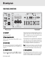
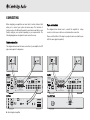
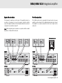
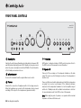
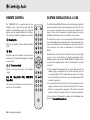
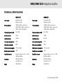
azur 540A/640A V2.0
Integrated amplifier
User’s manual
CONTENTS
Introduction .................................................................................................3
Safety precautions ......................................................................................4
Important safety instructions .....................................................................5
Rear panel connections..............................................................................6
Connecting...................................................................................................8
Front panel controls..................................................................................10
Remote control..........................................................................................12
Custom installation use ...........................................................................12
Multi-Room ................................................................................................13
CAP5 protection system ...........................................................................14
Troubleshooting.........................................................................................16
Technical specifications ...........................................................................17
Limited warranty .......................................................................................18
2 Azur integrated amplifier
540A/640A V2.0 Integrated amplifier
INTRODUCTION
Thank you for purchasing this Cambridge Audio Azur range amplifier.
These version 2 models are part of our commitment to the on-going
development of the Azur range. We hope that you will appreciate the
results and enjoy many years of listening pleasure from them.
For these version 2 models we have been able to further improve the
audio quality and make them more powerful through many detailed
changes and enhancements developed as a result of our on-going
research programme. We have also added some new features, including
support for Multi-Room use. All this proprietary engineering is housed
within our low resonance, acoustically damped chassis. An Azur
Navigator remote control is also provided, giving full remote control of
your amplifier in an attractive and easy to use handset.
About the 540A V2.0
The 540A V2.0 features a new preamp stage with buffered inputs for
lower crosstalk and improved stereo imaging, whilst the headphone
output is now provided be a separate Class A headphone driver circuit.
The amplifier stage has been revised with new low-noise input
transistors, special driver stage PSU regulation, a new voltage amplifier
topology and separate current sources for the voltage amplifier and predriver stages. These enhancements to the original circuits all work to
elevate the sound quality to a new level. A new heatsink and transformer
are employed and the power output is now 60 watts per channel (from
50 wpc on the V1 model).
Incognito Ready / Custom Install Use
Both the 540A V2.0 and 640A V2.0 now feature outputs for the new
Cambridge Audio Incognito system. By plugging in one or two external
Incognito Keypads and a power supply unit your V2.0 amplifier can
become the hub of a simple multi-room system. In addition, Control Bus
Input/Output and IR Emitter Input are provided to make it easy to
integrate these units into Custom Installation systems.
Your V2.0 amplifier can only be as good as the system it is connected to.
Please do not compromise on your source equipment, speakers or
cabling. Naturally we particularly recommend models from the
Cambridge Audio Azur range, which have been designed to the same
exacting standards as our amplifiers. Your dealer can also supply
excellent quality Cambridge Audio interconnects to ensure your system
realises its full potential.
Thanks for taking the time to read this manual, we do recommend you
keep it for future reference.
Matthew Bramble
Technical Director
About the 640A V2.0
Featuring all of the above enhancements, the 640A V2.0 also features
separate transformer secondaries for left and right channels, twin
rectifiers and separate PSU's for dual mono operation of the left and
right power amplifiers. An even larger heatsink and transformer are
employed and power output is now 75 watts per channel (from 65wpc
on the V1 model).
Azur integrated amplifier 3
SAFETY PRECAUTIONS
Checking the Power Supply Rating
For your own safety please read the following instructions carefully before attempting
to connect this unit to the mains.
Check that the rear of your unit indicates the correct supply voltage. If your mains
supply voltage is different, consult your dealer.
This unit is designed to operate only on the supply voltage and type that is
indicated on the rear panel of the unit. Connecting to other power sources may
damage the unit.
This equipment must be switched off when not in use and must not be used unless
correctly earthed. To reduce the risk of electric shock, do not remove the unit's
cover (or back). There are no user serviceable parts inside. Refer servicing to
qualified service personnel. If the power cord is fitted with a moulded mains plug
the unit must not be used if the plastic fuse carrier is not in place. Should you lose
the fuse carrier the correct part must be reordered from your Cambridge Audio
dealer.
The lightning flash with the arrowhead symbol within an equilateral
triangle is intended to alert the user to the presence of un-insulated
‘dangerous voltage’ within the product’s enclosure that may be of
sufficient magnitude to constitute a risk of electric shock to
persons.
The exclamation point within an equilateral triangle is intended to alert
the user to the presence of important operating and maintenance
instructions in the service literature relevant to this appliance.
This product complies with European Low
Voltage (73/23/EEC) and Electromagnetic Compatibility
(89/336/EEC) Directives when used and installed according to
this instruction manual. For continued compliance only
Cambridge Audio accessories should be used with this product
and servicing must be referred to qualified service personnel.
4 Azur integrated amplifier
The crossed-out wheeled bin is the European Union symbol for
indicating separate collection for electrical and electronic
equipment. This product contains electrical and electronic
equipment which should be reused, recycled or recovered and
should not be disposed of with unsorted regular waste. Please
return the unit or contact the authorised dealer from whom you
purchased this product for more information.
Plug Fitting Instructions (UK Only)
The cord supplied with this appliance is factory fitted with a 13 amp mains plug
fitted with a 3 amp fuse inside. If it is necessary to change the fuse, it is important
that a 3 amp one is used. If the plug needs to be changed because it is not suitable
for your socket, or becomes damaged, it should be cut off and an appropriate plug
fitted following the wiring instructions below. The plug must then be disposed of
safely, as insertion into a 13 amp socket is likely to cause an electrical hazard.
Should it be necessary to fit a 3-pin BS mains plug to the power cord the wires
should be fitted as shown in this diagram. The colours of the wires in the mains
lead of this appliance may not correspond with the coloured markings identifying
the terminals in your plug. Connect them as follows:
The wire which is coloured BLUE must be
connected to the terminal which is marked
with the letter ‘N’ or coloured BLACK.
The wire which is coloured BROWN must be
connected to the terminal which is marked
with the letter ‘L’ or coloured RED.
The wire which is coloured GREEN/YELLOW
must be connected to the terminal which is
marked with the letter ‘E’ or coloured GREEN.
If your model does not have an earth wire, then disregard this instruction.
If a 13amp (BS 1363) plug is used, a 3amp fuse must be fitted, or if any other type
of plug is used a 3amp or 5amp fuse must be fitted, either in the plug or adaptor,
or on the distribution board.
540A/640A V2.0 Integrated amplifier
IMPORTANT SAFETY INSTRUCTIONS
Please take a moment to read these notes before installing your Azur
amplifier, they will enable you to get the best performance and prolong
the life of the product. We advise you follow all instructions, heed all
warnings and keep the instructions for future reference.
The unit is of Class 1 construction and must be connected to a Mains
socket outlet with a protective earthing connection.
The unit requires ventilation above and below. Do not situate it on a rug
or other soft surface and do not obstruct any air inlet or outlet grilles on
the underside and top cover. Do not place in an enclosed area such as
a bookcase or in the cabinet.
Do not install near any heat sources such as radiators, heat register,
stove, or other apparatus (including amplifiers) that produce heat.
Do not defeat the safety purpose of the polarized or grounding type plug.
A polarized plug has two blades with one wider than the other. A
grounding type plug has two blades and a third grounding prong. The
wide blade or third prong are provided for your safety. If the provided
plug does not fit your outlet, consult an electrician for replacement of
the obsolete outlet.
WARNING - To reduce the risk of fire or electric shock, do not expose this
unit to rain or moisture. This unit must not be exposed to dripping or
splashing water or other liquids. No objects filled with liquid, such as
vases, shall be placed on the unit. In the event, switch off immediately,
disconnect from the mains supply and contact your dealer for advice.
It is recommended that when bi-amping, the same type power amplifiers
are used.
This unit must be disconnected from the mains socket to be turned off
completely. If you do not intend to use this unit for a long period of time,
unplug it from the mains socket. Unplug this unit during lightning
storms.
To clean the unit, wipe its case with a moist, lint-free cloth. Do not use
any cleaning fluids containing alcohol, ammonia or abrasives. Do not
spray an aerosol at or near the amplifier.
This unit is not user serviceable, never attempt to repair, disassemble or
reconstruct the unit if there seems to be a problem. Servicing is required
when the unit has been damaged in any way, such as power-supply cord
or plug is damaged, liquid has been spilled or objects have fallen into it,
the unit has been exposed to rain or moisture, does not operate
normally or has been dropped. A serious electric shock could result if
this precautionary measure is ignored.
This unit should be installed on a sturdy, level surface. Due to stray
magnetic fields turntables should not be located nearby due to
interference.
Ensure that small objects do not fall through any ventilation grille. If this
happens, switch off immediately, disconnect from the mains supply and
contact your dealer for advice.
Do not route the power cable so that it can be walked upon or damaged
by other items near it.
Azur integrated amplifier 5
REAR PANEL CONNECTIONS
CAP5
Right
Left
A
Right
In
6
Out
7
Pre-Out
Tape In
Tape In
Rec Out 1
Pre-Out
Rec Out 2
9
DMP / MP3
8
IR2
DVD
IR4
Left
Vol
Left
Auto
Clipping
Please refer to
your User's Manual
for more information
Right
A
Left
Right
B
Left
10
11
Right
Manufactured in an
ISO9002 approved facility
Control Bus
Loudspeaker short
Vorm öffnen des gerätes. Netzstecker ziehen.
3
azur 640A Integrated Amplifier V2.0
In
Tuner / DAB
4
Avis
Power AC
IR3
IR1
Keypad 2
International Patent Pending LeisureTech Electronics Pty Ltd
Temporary overload
Achtung
In
Keypad 1
5
2
Risk of electric shock. Do not open.
Risque de choc electrique. Ne pas ouvrir.
PSU
Fault requiring
service (DC)
Over temperature
Caution
IR Emitter
CD
Mains Voltage Selector Switch
115V/230V AC~50/60Hz
Impedance 4 - 8 ohms
Max Power Consumption: 700W
B
Off
Left
1
Multi-Room
Protection LED
indicators:
On
Aux
Power
Designed in London, England
www.cambridge-audio.com
Right
Impedance 4 - 8 ohms
Loudspeaker Terminals
Rec Out 1
Rec Out 2
DMP / MP3
DVD
Tuner / DAB
CD
Aux
Important
N1863
1
Please ensure that loudspeaker terminals are fully tightened
Veuillez s'assurer que les bornes de l'enceinte sont entièrement serrées
Power On/Off
Switches the unit on and off.
2
Mains voltage selector switch
Switches the mains voltage between 115V and 230V. For use by
installer/dealer only.
3
AC power socket
Once you have completed all connections to the amplifier, plug the AC
power cable into an appropriate mains socket. Your amplifier is now
ready for use.
4
Loudspeaker terminals
Two sets of loudspeaker terminals are available, A (main loudspeaker
terminals) and B (secondary switchable loudspeaker terminals).
6 Azur integrated amplifier
Caution Risk of electric shock. Do not open. Avis Risque de choc electrique. Ne pas ouvrir. Achtung Vorm öffnen des gërates. Netzstecker ziehen.
Connect the wires from your left channel loudspeaker to the LEFT + & terminals, and the wires from the right channel loudspeaker to the
RIGHT + & - terminals. In each case, the red terminal is the positive
output and the black terminal is the negative output.
Care should be taken to ensure no stray strands of wire are shorting speaker
outputs together. Please ensure that the loudspeaker terminals have been
tightened adequately to provide a good electrical connection. It is possible
for the sound quality to be affected if the screw terminals are loose.
Note: When using one pair of speakers, use speakers with a nominal
impedance of between 4-8 ohms. When using two pairs of speakers,
use speakers with a nominal impedance of between 6-8 ohms each.
5
IR (Infrared) Emitter In
Allows modulated IR commands from multi-room systems to be received by
the amplifier. Commands received here are not looped out of the Control
Bus. Refer to the ‘Custom Installation’ section for more information.
540A/640A V2.0 Integrated amplifier
6
Multi-room
PSU - Connect an Incogntio PS5 to supply power to the connected multiroom keypads/speakers.
Keypad 1/2 - Connect one or two Incogntio A-BUS KP10 keypads (or
other A-BUS compatible keypads) using CAT5/5e cable.
Incognito AS10 Active Ceiling Speakers can also be
connected here.
IR - Four IR outputs for remote control of source equipment.
Please refer to the ‘Multi-Room’ section of this manual for more
information on connections and set-ups.
7
Control Bus
In - Allows un-modulated commands from multi-rooms systems or other
components to be received by the unit.
Out - Loop out for control bus commands to another unit.
8
Pre-Out
Connect these sockets to the inputs on an external power amplifier(s) or
active subwoofer etc.
9
Tape In
Connect to a tape deck or to the analog output sockets on a MiniDisc,
portable digital music player or CD recorder using an interconnect cable
from the recorder's Line Out sockets to the amplifier's Tape In sockets.
recording. The source currently being listened to and (optionally)
recorded is then shown on the front panel by a corresponding blue LED.
However, when the Tape Mon Input is selected a second LED will
illuminate indicating that the Tape Monitor Input is now being listened to
with a different source being sent out of the Rec1/Rec2 outputs for
recording. The recording source is shown by the first LED and can be
changed by pressing the other source buttons. To switch Tape Monitor
off, simply press the Tape Mon button again, toggling this function off.
This feature is most useful when using 3-head analog cassette decks
which allow the signal being recorded to be played back live off tape (via
a 3rd head) whilst it is simultaneously recorded. It is then possible by
toggling the Tape Monitor input on and off to compare directly in real
time the original and recorded signal so that adjustments to the
recording parameters of the tape machine can be made (consult the
manual of your 3-head analog cassette deck for full details).
10
Record Out 1/2
These two identical output sockets can be connected to a tape deck or
to the analog Record In sockets on a MiniDisc or CD recorder.
11
DMP/MP3, DVD, Tuner/DAB, CD, Aux
These inputs are suitable for any 'line level' source equipment such as
digital music players (DMP) and MP3 players, CD players, DAB or FM/AM
tuners etc.
Note: These inputs are for analog audio signals only. They should not be
connected to the digital output of a CD player or any other digital device.
The Tape Input circuit of the 540A/640A V2.0 is a "monitor" type,
different from the other 5 inputs. For the 5 normal inputs, the source
selected for listening to will be sent out of the Rec 1/Rec 2 outputs for
Azur integrated amplifier 7
CONNECTING
When designing our amplifiers we have tried to include features that
allow you to connect your system in various ways. The inclusion of
features such as Pre-Out and Speaker B connections mean that you can
flexibly configure your system depending on your requirements. The
following diagrams are designed to make connection easy.
Tape connection
The diagram below shows how to connect the amplifier to a tape
recorder or other source with a record and monitor connection.
Please note that either of the tape loop outputs can be used (as they are
both the same signal in parallel).
Basic connection
The diagram below shows the basic connection of your amplifier to a CD
player and a pair of loudspeakers.
Amplifier
In
CAP5
Power
www.cambridge-audio.com
Control Bus
On
In
Off
Max Power Consumption: 700W
Out
Left
B
Right
Left
A
Right
Mains Voltage Selector Switch
115V/230V AC~50/60Hz
Over temperature
Control Bus
In
Out
Pre-Out
Tape In
Rec Out 1
Rec Out 2
Power AC
DMP / MP3
Pre-Out
Tape In
Rec Out 1
Rec Out 2
DMP / MP3
DVD
Tuner / DAB
CD
Aux
Loudspeaker short
Vorm öffnen des gerätes. Netzstecker ziehen.
Left
Aux
Tuner / DAB
CD
DVD
DMP / MP3
Rec Out 2
Rec Out 1
Tape In
Pre-Out
Left
Right
Right
Vol
Left
Auto
Clipping
A
Left
B
Right
Left
Impedance 4 - 8 ohms
Manufactured in an
ISO9002 approved facility
Pre-Out
Tape In
Rec Out 1
Rec Out 2
DMP / MP3
DVD
Tuner / DAB
CD
Please refer to
your User's Manual
for more information
Right
A
Left
Right
B
Left
Right
Impedance 4 - 8 ohms
Loudspeaker Terminals
Aux
Important
Right
Right
Loudspeaker Terminals
Important
Please ensure that loudspeaker terminals are fully tightened
Veuillez s'assurer que les bornes de l'enceinte sont entièrement serrées
N1863
Caution Risk of electric shock. Do not open. Avis Risque de choc electrique. Ne pas ouvrir. Achtung Vorm öffnen des gërates. Netzstecker ziehen.
CD Player
Please ensure that loudspeaker terminals are fully tightened
Veuillez s'assurer que les bornes de l'enceinte sont entièrement serrées
Caution Risk of electric shock. Do not open. Avis Risque de choc electrique. Ne pas ouvrir. Achtung Vorm öffnen des gërates. Netzstecker ziehen.
Tape / MD Player
Class 1 Laser Product
Luokan 1 Laserplaite
Klass 1 Laserapparat
Line Output
In
Out
IR Emitter
In
Right
Manufactured in an
ISO9002 approved facility
8 Azur integrated amplifier
azur 640C Compact Disc Player V2.0
Max Power Consumption: 18W
Line Output
Power AC
Designed in London, England
Digital Outputs
Left
Right
Power Off
Left
Control Bus
Mains Voltage Selector Switch (50 / 60Hz)
On
IR4
DVD
Achtung
Left
Auto
Clipping
N1863
IR2
azur 640A Integrated Amplifier V2.0
Tuner / DAB
Risque de choc electrique. Ne pas ouvrir.
Vol
IR3
Temporary overload
Risk of electric shock. Do not open.
Loudspeaker short
Vorm öffnen des gerätes. Netzstecker ziehen.
Please refer to
your User's Manual
for more information
IR1
Keypad 2
International Patent Pending LeisureTech Electronics Pty Ltd
Avis
Power AC
Keypad 1
CD
Achtung
In
IR4
Caution
Avis
Manufactured in an
ISO9002 approved facility
PSU
In
Aux
IR2
Temporary overload
Risk of electric shock. Do not open.
Risque de choc electrique. Ne pas ouvrir.
IR Emitter
Fault requiring
service (DC)
Over temperature
International Patent Pending LeisureTech Electronics Pty Ltd
Caution
Multi-Room
Protection LED
indicators:
Designed in London, England
Impedance 4 - 8 ohms
In
Fault requiring
service (DC)
Mains Voltage Selector Switch
115V/230V AC~50/60Hz
azur 640A Integrated Amplifier V2.0
IR3
Keypad 2
Right
Max Power Consumption: 700W
Keypad 1
A
IR1
PSU
Left
Multi-Room
IR Emitter
Right
Off
Impedance 4 - 8 ohms
CAP5
Protection LED
indicators:
On
B
Power
Designed in London, England
www.cambridge-audio.com
Left
Amplifier
S/P DIF
Co-axial
Toslink
Optical
Caution
Risk of electric shock
Do not open
Avis
Risque de choc electrique
Ne pas ouvrir
Achtung
Vorm offnen des gerates
Netzstecker ziehen
www.cambridge-audio.com
Rec Out
Rec In
540A/640A V2.0 Integrated amplifier
Speaker B connections
Pre-Out connections
The Speaker B connections on the back of the amplifier allow for a
second set of speakers to be used (ie speakers located in another
room). The Speaker B button on the front panel allows this second set
of speakers to be switched on and off.
The Pre-Out sockets are for connecting to the input sockets of a power
amplifier or active subwoofer. The diagram below shows how to connect
the amplifier to an active subwoofer via the Line In inputs on the
subwoofer.
Note: When using two pairs of speakers, use speakers with a nominal
impedance of between 6-8 ohms each.
Active subwoofer, etc
Amplifier
azur 640A Integrated Amplifier V2.0
Impedance 4 - 8 ohms
In
Control Bus
Keypad 2
CAP5
Power
Out
Off
Max Power Consumption: 700W
Left
B
Right
Left
A
Right
Out
Pre-Out
Tape In
Rec Out 1
Rec Out 2
DMP / MP3
Power AC
Aux
CD
DVD
Tuner / DAB
DMP / MP3
Rec Out 2
Rec Out 1
Tape In
Pre-Out
Achtung
Pre-Out
Tape In
Rec Out 1
Rec Out 2
DMP / MP3
DVD
Tuner / DAB
CD
Aux
Loudspeaker short
Vorm öffnen des gerätes. Netzstecker ziehen.
Left
Left
Right
Right
IR4
DVD
Risque de choc electrique. Ne pas ouvrir.
Left
IR2
Temporary overload
Auto
Vol
Clipping
Left
Auto
Clipping
A
Left
B
Right
Left
Impedance 4 - 8 ohms
Pre-Out
Tape In
Rec Out 1
Rec Out 2
DMP / MP3
DVD
Tuner / DAB
CD
Aux
Please refer to
your User's Manual
for more information
Manufactured in an
ISO9002 approved facility
Right
A
B
Right
Left
Right
Impedance 4 - 8 ohms
Loudspeaker Terminals
Important
Please ensure that loudspeaker terminals are fully tightened
Veuillez s'assurer que les bornes de l'enceinte sont entièrement serrées
Left
Right
Right
Loudspeaker Terminals
N1863
Control Bus
In
International Patent Pending LeisureTech Electronics Pty Ltd
Caution
Risk of electric shock. Do not open.
Avis
Vol
azur 640A Integrated Amplifier V2.0
IR3
Keypad 2
Tuner / DAB
IR4
Loudspeaker short
Please refer to
your User's Manual
for more information
Keypad 1
CD
Power AC
Important
Caution Risk of electric shock. Do not open. Avis Risque de choc electrique. Ne pas ouvrir. Achtung Vorm öffnen des gërates. Netzstecker ziehen.
Please ensure that loudspeaker terminals are fully tightened
Veuillez s'assurer que les bornes de l'enceinte sont entièrement serrées
Caution Risk of electric shock. Do not open. Avis Risque de choc electrique. Ne pas ouvrir. Achtung Vorm öffnen des gërates. Netzstecker ziehen.
CD Player
In
Out
IR Emitter
In
Digital Outputs
Left
Right
Power Off
Left
On
Right
azur 640C Compact Disc Player V2.0
S/P DIF
Co-axial
Toslink
Optical
Caution
Risk of electric shock
Do not open
Avis
Risque de choc electrique
Ne pas ouvrir
Achtung
Vorm offnen des gerates
Netzstecker ziehen
www.cambridge-audio.com
Control Bus
Mains Voltage Selector Switch (50 / 60Hz)
On
Max Power Consumption: 18W
Line Output
Power AC
Manufactured in an
ISO9002 approved facility
Class 1 Laser Product
Luokan 1 Laserplaite
Klass 1 Laserapparat
Line Output
Control Bus
Mains Voltage Selector Switch (50 / 60Hz)
Designed in London, England
Power Off
In
Out
IR Emitter
In
Right
azur 640C Compact Disc Player V2.0
Max Power Consumption: 18W
Line Output
Power AC
Manufactured in an
ISO9002 approved facility
Designed in London, England
Digital Outputs
Left
Right
Class 1 Laser Product
Luokan 1 Laserplaite
Klass 1 Laserapparat
Left
CD Player
N1863
Line Output
Achtung
Vorm öffnen des gerätes. Netzstecker ziehen.
Manufactured in an
ISO9002 approved facility
In
Aux
IR2
Temporary overload
Avis
Risque de choc electrique. Ne pas ouvrir.
PSU
In
Over temperature
International Patent Pending LeisureTech Electronics Pty Ltd
Caution
IR1
IR Emitter
Fault requiring
service (DC)
Mains Voltage Selector Switch
115V/230V AC~50/60Hz
Over temperature
Risk of electric shock. Do not open.
Multi-Room
Protection LED
indicators:
www.cambridge-audio.com
On
In
Right
IR3
Designed in London, England
In
Fault requiring
service (DC)
Mains Voltage Selector Switch
115V/230V AC~50/60Hz
Keypad 1
A
Max Power Consumption: 700W
PSU
Left
IR1
IR Emitter
Right
Off
Impedance 4 - 8 ohms
Multi-Room
Protection LED
indicators:
On
B
CAP5
Power
Designed in London, England
www.cambridge-audio.com
Left
Amplifier
S/P DIF
Co-axial
Toslink
Optical
Caution
Risk of electric shock
Do not open
Avis
Risque de choc electrique
Ne pas ouvrir
Achtung
Vorm offnen des gerates
Netzstecker ziehen
www.cambridge-audio.com
Azur integrated amplifier 9
FRONT PANEL CONTROLS
azur 640A
Integrated Amplifier
Volume
4
Bass
7
Treble
8
Balance
Protection
Standby / On
1
1
2
Phones
Speaker B
Direct
3
5
6
Standby/On
Switches the unit between Standby mode (indicated by dim power LED)
and On (indicated by bright power LED). Standby is a low power mode
where the power consumption is less than 10 Watts. The unit should be
left in Standby mode when not in use.
2
Infrared sensor
Receives IR commands from the supplied Azur remote control.
3
Phones
Allows for the connection of headphones with a ¼" Jack plug connector.
When the headphones are connected, the loudspeaker relay is released
switching off the output to the loudspeakers (speakers A and B).
Aux
9
4
CD
Tuner / DAB
10
DVD
DMP / MP3
Tape Mon
11
Protection
LED flashes to indicate activation of CAP5 protection system. Refer to
the CAP5 section of this manual for more information.
5
Speaker B
Turns on/off the secondary set of loudspeaker terminals on the back
panel. This can be used for listening to an extra set of loudspeakers in
another room.
Please note that care should be taken when selecting if two loudspeakers
are going to be used on each channel. If the combined resistance
measured on the loudspeaker terminals is too low the amplifier may not
switch out of Standby mode until a suitable load resistance is detected.
For more information refer to the CAP5 section of this manual.
Note: When using two pairs of speakers, use speakers with a nominal
impedance of between 6-8 ohms each.
10 Azur integrated amplifier
540A/640A V2.0 Integrated amplifier
6
Direct
This control gives the audio signal a more direct path to the power
amplifier stage of your amplifier, bypassing the tone control circuits for
the purest possible sound quality.
7
Bass and Treble
These controls allow subtle adjustments to the tonal balance of the
sound. In the central position these controls have no effect. These
controls only modify the sound through your loudspeakers and the PreOut sockets, they do not affect the signals sent through the Tape Out
connections. With a well produced CD and a good system the tone
controls are unnecessary and can be switched out by the Direct switch.
If the musical recording is of poor quality or other factors are affecting
the sound quality, it may be necessary to adjust the tone controls to
compensate.
8
10
Aux, CD, Tuner/DAB, DVD, DMP/MP3
Push the appropriate input selection button to select the source
component that you wish to listen to. The signal selected is also fed to
the Tape Out sockets so that it may be recorded. The input should not
be changed whilst recording (but the recorded signal can be checked
using the tape input Tape Monitor).
11
Tape Monitor
This control lets you listen to the output signal from a tape recorder or
signal processor connected to the amplifier's Tape In/Rec Out sockets.
When Tape Monitor is selected, the source component chosen by the
input selection push buttons continues to be routed to the Rec Out
sockets for recording or processing.
Volume
Use to increase/decrease the level of the sound from the outputs of the
amplifier. This control affects the level of the loudspeaker output, the
pre-amp output and the headphone output. It does not affect the Tape
Out connections. It is advisable to turn the Volume control fully anticlockwise before switching the amplifier on.
9
Balance
This control allows you to adjust the relative output levels of the left and
right channels. In the central position the output from each channel is
equal. This control only modifies the sound through your loudspeakers
and the Pre-Out sockets, it does not affect the signals sent through the
Tape Out connections.
Azur integrated amplifier 11
REMOTE CONTROL
CUSTOM INSTALLATION (C.I.) USE
The 540A/640A V2.0 is supplied with an Azur
Navigator remote control that operates both this
amplifier and Cambridge Audio Azur range CD
players. Insert the supplied AAA batteries to activate.
The functions relevant to the amplifier are as follows:
The 540A V2.0 and 640A V2.0 feature a Control Bus input/output that
allow un-modulated remote control commands (positive logic, TTL level)
to be received electrically by the unit and looped to another unit if
desired. These control commands are typically generated by custom
installation (multi-room) systems or remote IR receiver systems.
Standby/On
Switches the amplifier between On and Standby
mode.
Prog
Mute
Remain
Vol
In addition the units feature 'direct' IR/Control codes as well as toggle
codes for some of their features to simplify programming custom
installation systems. Special direct On/Off and Mute commands can be
accessed on the supplied remote control for teaching into C.I. systems
as follows:
Intro
Random
Space
1. Press and hold the Standby button. The remote first generates it's
standby (toggle) command. Keep the button held down, after 12
seconds an amplifier “On” command will be generated. If the button
is kept held down for a further 12 seconds, an amplifier player “Off”
command is generated.
Aux
CD
Tuner
DAB
DVD
DMP
MP3
Tape
Mon
Mutes the audio on the amplifier. The mute mode is
indicated by the channel LED flashing. Press again
to cancel mute.
Vol
Volume controls
Increase or decrease the volume of the amplifier
output.
Aux, CD, Tuner/DAB, DVD, DMP/MP3,
Tape Mon
The six source select buttons are used to change the
input source to the amplifier.
The Control Bus sockets are colour-coded orange. An IR Emitter Input is
also provided that allows modulated IR remote control commands to be
received electrically by the unit. Commands on this input operate the
unit only and are not looped out demodulated on the Control Bus
Output.
A-B
Repeat
2. Press and hold the Mute button. The remote first generates it's mute
(toggle) command. Keep the button held down, after 12 seconds a
“Mute on” command will be generated. If the button is kept held
down for a further 12 seconds, a “Mute off” command is generated.
A full code table for this product is available on the Cambridge Audio
website at www.cambridge-audio.com.
12 Azur integrated amplifier
540A/640A V2.0 Integrated amplifier
MULTI-ROOM
The Azur V2.0 amplifiers feature Incognito ReadyTM / A-BUSTM Ready
outputs, allowing multi-room capability. One or two amplified keypads
(and an external PSU power supply) can be plugged into the amplifier
(using Cat5/5e cable and RJ45 plugs) to provide multi-room audio in
one or two secondary rooms or zones. The keypads are powered by an
external PSU via Cat5/5e cables and no mains connection is required in
the secondary rooms.
Speakers (eg SS10)
connected via
speaker cable
KP10-EU keypad
The keypads operate independently of the amplifier in terms of
volume/bass/treble etc and can be independently turned on and off,
however they can only listen to the same source as selected on the
amplifier.
Cat5/5e
PS5
CAP5
IR Emitter
PSU
In
In
Left
A
Right
Fault requiring
service (DC)
Mains Voltage Selector Switch
115V/230V AC~50/60Hz
Keypad 1
azur 640A Integrated Amplifier V2.0
IR3
Control Bus
Keypad 2
In
Out
Over temperature
International Patent Pending LeisureTech Electronics Pty Ltd
Caution
IR2
IR4
Temporary overload
Pre-Out
Tape In
Rec Out 1
Rec Out 2
Power AC
DMP / MP3
Achtung
DVD
Risque de choc electrique. Ne pas ouvrir.
Tuner / DAB
Avis
CD
Risk of electric shock. Do not open.
Aux
Pre-Out
Tape In
Rec Out 1
Rec Out 2
DMP / MP3
DVD
Tuner / DAB
CD
Aux
Loudspeaker short
Vorm öffnen des gerätes. Netzstecker ziehen.
Left
Vol
Left
Auto
Clipping
Please refer to
your User's Manual
for more information
Manufactured in an
ISO9002 approved facility
Right
A
Left
B
Right
Left
Right
Right
Impedance 4 - 8 ohms
Loudspeaker Terminals
Important
N1863
Please ensure that loudspeaker terminals are fully tightened
Veuillez s'assurer que les bornes de l'enceinte sont entièrement serrées
Caution Risk of electric shock. Do not open. Avis Risque de choc electrique. Ne pas ouvrir. Achtung Vorm öffnen des gërates. Netzstecker ziehen.
Mini-jack lead
IR10
azur 640C
Compact Disc Player
Open
Close
Standby / On
Class 1 Laser Product
Luokan 1 Laserplaite
Klass 1 Laserapparat
Power Off
In
Out
IR Emitter
In
Right
Designed in London, England
azur 640C Compact Disc Player V2.0
Max Power Consumption: 18W
Line Output
Power AC
Manufactured in an
ISO9002 approved facility
Skip
Scan
Stop
Digital Outputs
Left
Right
On
Left
Control Bus
Mains Voltage Selector Switch (50 / 60Hz)
Play
Pause
Line Output
For full details on the Incognito multi-room system please contact your
local Cambridge Audio dealer.
IR1
Right
Off
Impedance 4 - 8 ohms
To allow control of your source equipment from the remote rooms an IR
emitter (IR10) is plugged into one of the IR outputs on the rear of the
unit and then attached over the IR window of the source unit.
Alternatively, on our own products that feature IR emitter Inputs, a minijack to mini-jack lead can be used. Commands received by the keypads
can now be sent back to the source equipment via the amplifier. It is
then possible to control the source equipment from the remote rooms by
using the source equipment's own remote controls or through a learning
remote. The Incogntio LR10 can fully control the keypads, “learn” the
source's remote controls and change source input on the amplifier etc.
Multi-Room
Protection LED
indicators:
On
B
Power
Designed in London, England
www.cambridge-audio.com
Max Power Consumption: 700W
Left
A-BUS is a standard that allows compatibility between different
manufacturers equipment, so A-BUS compatible keypads from other
manufacturers can be used. If used with our own Incognito KP10
keypads, there are some extra features such as the ability to change
source on the amplifier from the keypad.
LR10
S/P DIF
Co-axial
Toslink
Optical
Caution
Risk of electric shock
Do not open
Avis
Risque de choc electrique
Ne pas ouvrir
Achtung
Vorm offnen des gerates
Netzstecker ziehen
www.cambridge-audio.com
Azur integrated amplifier 13
CAP5 - FIVE WAY PROTECTION SYSTEM
Cambridge Audio has developed a proprietary protection system to
ensure reliability and a long life to its amplifiers. This protection system
comprises of five main protection methods:
amplifier is working harder. If the amplifier is mounted in a cabinet or the
ventilation slots are obstructed the over temperature detection may
activate/reactivate after a short listening time.
1. DC detection
Remedy - User related fault. The internal temperature of the output
transistors has reached the over temperature limit. The unit is not
damaged, although it should be left for 15 minutes to cool down before
being switched out of Standby.
Indicator - Unit has switched off during operation, protection LED
constantly flashes in single bursts.
Description - CAP5 offers loudspeaker protection if the output of the
amplifier goes to a high constant voltage (DC) because of some internal
fault. This is a rare fault although detecting it could just save those
expensive loudspeakers.
Remedy - Due to the necessary sensitivity of the DC protection circuit,
hard clipping of the amplifier may cause DC protection to be triggered.
If this fault occurs please switch the unit off, power up again and check
operation with a reduced volume level. If the DC fault occurs again
please contact your dealer for service.
2. Over temperature detection
Indicator - Unit has switched off during operation, protection LED
constantly flashes in bursts of two.
Description - CAP5 includes temperature detection which constantly
monitors the heat generated by the output transistors. If the monitored
temperature reaches a high level (suitably within the limits of the output
devices) the amplifier will automatically switch into a fault mode. The unit
should ideally be left for 15 minutes in this state to cool down adequately.
If the unit has not fully cooled down then the temperature may reach the
limit soon after the amplifier is powered up. If the loudspeaker
impedance is low the temperature of the amplifier may rise faster as the
14 Azur integrated amplifier
3. Overvoltage/overcurrent detection
Indicator - The unit attempts to come out of Standby mode, the
protection LED flashes in bursts of three.
Description - CAP5 offers V/I protection by constantly monitoring the
output transistors to keep them working inside their Safe Operating Area
(SOA). The SOA is a set of limits given by the output transistor
manufacturer to ensure reliability. Many amplifier designers include V/I
limiting in the signal path which can degrade the signal by compressing
dynamics. The CAP5 system operates outside the signal path and when
triggered shuts down the amp rather than limits the size of the signal
passing through the amp (signal compression). V/I also protects the
amplifier against short circuits on the speaker terminals during use.
Remedy - The resistance on the loudspeaker terminals is too low. Check
to see if there is a short circuit between the loudspeaker terminals.
Note: If the indication remains the same and multiple loudspeakers are
being used on each loudspeaker output then please remove a pair and
retry. If too many loudspeakers are connected to any amplifier causing
the load resistance to drop too low the amplifier will overheat. CAP5 will
detect this situation. If the indication remains the same with only one
set of loudspeakers connected, there may be a fault with one or both of
the loudspeakers.
540A/640A V2.0 Integrated amplifier
4. Short circuit detection
Indicator - Unit has switched off during operation, protection LED flashes
constantly in bursts of four.
Description - During power up from Standby CAP5 performs a check on
the loudspeaker terminals to see if a short across the terminals has
been accidentally introduced. If the resistance measured across the
loudspeaker terminals is too low the unit will stay in Standby mode until
the fault has been removed and Power up is re-attempted.
It is possible to disable the clipping detection feature by holding down
the Standby/On button during power up (whilst plugging the unit into the
mains power). The unit will indicate this by flashing the protection LED
for several seconds.
Note: Disabling the clipping detection is not advised as this feature has
been added deliberately to protect the amplifier and loudspeakers.
Remedy - User related fault. There may be a short circuit between the
loudspeaker terminals. Check all loudspeaker connections before
attempting to switch the unit out of Standby.
5. Intelligent clipping detection
Indicator - Volume is nudged down automatically.
Description - CAP5 has the ability to detect when the amplifier starts to
clip or overdrive at it’s output, which can damage loudspeakers, and
degrade the sound. Clipping distortion is caused at high volume levels
when the output signal briefly goes outside the maximum voltage that
the amplifier can provide, causing the tops of the signal to flatten off.
When CAP5 detects clipping the volume will be automatically nudged
down until CAP5 detects an undistorted output.
Volume
Clipping
Azur integrated amplifier 15
TROUBLESHOOTING
There is no power
There is a loud buzz or hum
Ensure the AC power cord is connected securely.
Check turntable or tone arm for ground and connection lead fault.
Ensure the plug is fully inserted into the wall socket and is switched on.
Ensure no interconnects are loose or defective.
Check fuse in the mains plug or adaptor.
Ensure that your tape deck/turntable is not too close to the amplifier.
There is no sound
Unable to make or play tape recordings
Make sure the unit is not in Standby mode.
Check that TAPE MON and TAPE OUT have been connected correctly.
Check that source component is properly connected.
Check that 'TAPE MON' is not switched on (unless tape input is required).
There is weak bass or diffused stereo imaging
Check that your speakers are properly connected.
Ensure that speakers are not wired out of phase.
If using Speaker B terminals check they are switched on.
If channel LED is flashing turn mute off.
Protection LED flashing
See section on CAP5 protection system.
There is no sound on one channel
Ensure that balance control is in the correct position.
Check speaker connections.
Check interconnects.
16 Azur integrated amplifier
540A/640A V2.0 Integrated amplifier
TECHNICAL SPECIFICATIONS
540A V2.0
640A V2.0
Power output
60 watts (into 8Ω)
90 watts (into 4Ω)
Power output
75 watts (into 8Ω)
120 watts (into 4Ω)
THD (unweighted)
<0.002% @ 1kHz, of rated power
<0.070% 20Hz - 20kHz, of rated power
<0.025% 20Hz - 20kHz @ 10w
THD (unweighted)
<0.002% @ 1kHz, of rated power
<0.050% 20Hz - 20kHz, of rated power
<0.020% 20Hz - 20kHz @ 10w
Frequency response (-1dB)
5Hz - 50kHz
Frequency response (-1dB)
5Hz - 50kHz
S/N ratio (ref 1w)
>85dB
S/N ratio (ref 1w)
>90dB
Input impedances
47kohms
Input impedances
47kohms
Power Amp damping factor
>100
Power Amp damping factor
>100
Max power consumption
650w
Max power consumption
700w
Min/On power consumption
<35w (no signal)
Min/On power consumption
<35w (no signal)
Standby power consumption
<10w
Standby power consumption
<10w
Bass/Treble controls
Shelving, ultimate boost/cut + /-7.5dB
@ 20Hz and 20kHz
Bass/Treble controls
Shelving, ultimate boost/cut + /-7.5dB
@ 20Hz and 20kHz
Dimensions
100 x 430 x 310mm
(3.9 x 16.9 x 12.2”)
Dimensions
100 x 430 x 310mm
(3.9 x 16.9 x 12.2”)
Weight
7.4kg (16.3Lbs)
Weight
7.4kg (16.3Lbs)
Azur integrated amplifier 17
LIMITED WARRANTY
Cambridge Audio warrants this product to be free from defects in
materials and workmanship (subject to the terms set forth below).
Cambridge Audio will repair or replace (at Cambridge Audio's option) this
product or any defective parts in this product. Warranty periods may vary
from country to country. If in doubt consult your dealer and ensure that
you retain proof of purchase.
To obtain warranty service, please contact the Cambridge Audio
authorised dealer from which you purchased this product. If your dealer
is not equipped to perform the repair of your Cambridge Audio product,
it can be returned by your dealer to Cambridge Audio or an authorised
Cambridge Audio service agent. You will need to ship this product in
either its original packaging or packaging affording an equal degree of
protection.
Proof of purchase in the form of a bill of sale or receipted invoice, which
is evidence that this product is within the warranty period, must be
presented to obtain warranty service.
This Warranty is invalid if (a) the factory-applied serial number has been
altered or removed from this product or (b) this product was not
purchased from a Cambridge Audio authorised dealer. You may call
Cambridge Audio or your local country Cambridge Audio distributor to
confirm that you have an unaltered serial number and/or you purchased
from a Cambridge Audio authorised dealer.
This Warranty does not cover cosmetic damage or damage due to acts
of God, accident, misuse, abuse, negligence, commercial use, or
modification of, or to any part of, the product. This Warranty does not
cover damage due to improper operation, maintenance or installation,
or attempted repair by anyone other than Cambridge Audio or a
18 Azur integrated amplifier
Cambridge Audio dealer, or authorised service agent which is authorised
to do Cambridge Audio warranty work. Any unauthorised repairs will void
this Warranty. This Warranty does not cover products sold AS IS or WITH
ALL FAULTS.
REPAIRS OR REPLACEMENTS AS PROVIDED UNDER THIS WARRANTY
ARE THE EXCLUSIVE REMEDY OF THE CONSUMER. CAMBRIDGE AUDIO
SHALL NOT BE LIABLE FOR ANY INCIDENTAL OR CONSEQUENTIAL
DAMAGES FOR BREACH OF ANY EXPRESS OR IMPLIED WARRANTY IN
THIS PRODUCT. EXCEPT TO THE EXTENT PROHIBITED BY LAW, THIS
WARRANTY IS EXCLUSIVE AND IN LIEU OF ALL OTHER EXPRESS AND
IMPLIED WARRANTIES WHATSOEVER INCLUDING, BUT NOT LIMITED TO,
THE WARRANTY OF MERCHANTABILITY AND FITNESS FOR A PRACTICAL
PURPOSE.
Some countries and US states do not allow the exclusion or limitation of
incidental or consequential damages or implied warranties so the above
exclusions may not apply to you. This Warranty gives you specific legal
rights, and you may have other statutory rights, which vary from state to
state or country to country.
540A/640A V2.0 Integrated amplifier
This guide is designed to make installing and using this product as easy as
possible. Information in this document has been carefully checked for accuracy at
the time of printing; however, Cambridge Audio's policy is one of continuous
improvement, therefore design and specifications are subject to change without
prior notice. If you notice any errors please feel free to email us at:
[email protected]
This document contains proprietary information protected by copyright. All rights
are reserved. No part of this manual may be reproduced by any mechanical,
electronic or other means, in any form, without prior written permission of the
manufacturer. All trademarks and registered trademarks are the property of their
respective owners.
Incognito and Incognito Ready are trademarks of Cambridge Audio Ltd. All rights
reserved.
© Copyright Cambridge Audio Ltd 2006
A-BUS and A-BUS Ready are registered trademarks of LeisureTech Electronics Pty
Ltd Australia.
Azur integrated amplifier 19
azur 540A/640A V2.0
www.cambridge-audio.com
Part No. AP18376/2