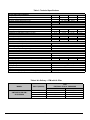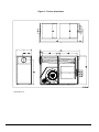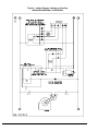
1
Installation Instructions
and Homeowner’s Manual
WARM AIR FURNACE
OIL FIRED - UPFLOW
Models:
AMT400B34-SM1PMA
OLR350H28B
Manufactured by:
Dettson Industries Inc
3400, Industrial Boulevard
Sherbrooke, Qc, Canada, J1L 1V8
www.dettson.ca
Attention
Do not tamper with the unit
or its controls.
Call a
qualified service technician.
Printed in Canada on 100% recycled paper
INSTALLER / SERVICE TECHNICIAN :
Use the information in this manual for the installation / servicing of the furnace
and keep the document near the unit for future reference.
HOMEOWNER :
Please keep this manual near the furnace for future reference.
2013-05-30
X40096 Rev. J
TABLE OF CONTENTS
1
SAFETY REGULATIONS
3
1.1
1.2
1.3
1.4
SAFETY LABELING AND WARNING
SIGNS
IMPORTANT INFORMATION
DETECTION SYSTEMS
DANGER OF FREEZING
3
3
3
3
2
INSTALLATION
4
2.1
2.2
2.3
2.3.1
2.3.2
2.4
2.4.1
2.4.2
2.4.3
2.5
4
4
4
4
4
5
5
5
5
2.6.1
2.6.2
2.7
2.8
2.8.1
2.9
2.9.1
POSITIONING THE FURNACE
ELECTRICAL SYSTEM
INSTALLATION OF THE BURNER
Nozzles
Air and Turbulator Settings
VENTING
Masonry chimney
Factory Built Chimneys
Draft Regulator
BLOCKED VENT SHUT-OFF DEVICE
(BVSO) FOR CHIMNEY VENTING
BVSO Performance Test
COMBUSTION AIR SUPPLY AND
VENTILATION
Contaminated Combustion Air
Burner with Outdoor Combustion Air Kit
OIL TANK
DUCTING
Air filter
INSTALLATION OF ACCESSORIES
Air Conditioner (or Heat Pump)
3
OPERATION
7
3.1
3.2
START-UP
SEQUENCE OF OPERATION BECKETT
AFG / RIELLO 40-F
CHECKS AND ADJUSTMENTS
Purging the oil line
Pressure adjustment
Combustion Check
Draft Regulator adjustment
Overfire pressure test
Vent Temperature Test
Blower motor test
Fan limit adjustment
Supply Air Temperature Rise Test
Limit Control Check
Restart after Burner Failure
7
2.5.1
2.6
3.3
3.3.1
3.3.2
3.3.3
3.3.4
3.3.5
3.3.6
3.3.7
3.3.8
3.3.9
3.3.10
3.3.11
4
4.1
4.2
MAINTENANCE
10
4.3
4.4
4.5
4.6
4.7
4.8
4.9
CLEANING THE HEAT EXCHANGER 10
CLEANING THE BLOCKED VENT SHUTOFF DEVICE (BVSO)
10
CLEANING OF THE BURNER HEAD
10
REPLACING THE NOZZLE
10
REPLACING THE OIL FILTER
10
REPLACING THE AIR FILTER
10
MOTOR LUBRICATION
11
Pulley alignment
11
Belt replacement
11
5
FURNACE INFORMATION
5
5
12
INDEX OF TABLES
TABLE 1:
TABLE 2:
TABLE 3:
TABLE 4:
TABLE 5:
BLOWER ADJUSTMENT
PULLEY ADJUSTMENT
TECHNICAL SPECIFICATIONS
AIR DELIVERY - CFM WITH AIR FILTER
MINIMUM CLEARANCES – COMBUSTIBLE
MATERIALS - CANADA
TABLE 6: MINIMUM CLEARANCES – COMBUSTIBLE
MATERIALS -USA
TABLE 7: PARTS LIST
5
6
6
6
6
6
6
6
7
7
7
7
8
8
8
8
8
9
9
9
9
8
8
13
13
14
14
20
INDEX FIGURES
FIGURE 1
FIGURE 2
FIGURE 3
FIGURE 4
FIGURE 5
FIGURE 6
FIGURE 7
FIGURE 8
FIGURE 9
2
PULLEY ADJUSTMENT
9
HIGH LIMIT ADJUSTMENT
9
PULLEY ADJUSTMENT
11
BELT TENSION VERIFICATION
11
FURNACE DIMENSIONS
15
LADDER DIAGRAM, HEATING AND COOLING 16
WIRING DIAGRAM, HEATING AND COOLING 17
WIRING DIAGRAM, HEATING
18
PARTS LIST
19
1 SAFETY REGULATIONS
1.1
WARNING
SAFETY LABELING AND WARNING
SIGNS
The words DANGER, WARNING AND CAUTION are used to
identify the levels of seriousness of certain hazards. It is
important that you understand their meaning. You will notice
these words in the manual as follows:
DANGER
Immediate hazards that WILL result in death, serious
bodily injury and/or property damage.
WARNING
Installations and repairs performed by unqualified
persons can result in hazards to them and to others.
Installations must conform to local codes or, in the
absence of same, to codes of the country having
jurisdiction.
The information contained in this manual is intended
for use by a qualified technician, familiar with safety
procedures and who is equipped with the proper tools
and test instruments.
Failure to carefully read and follow all instructions in
this manual can result in death, bodily injury and/or
property damage.
1.3
Hazards or unsafe practices that CAN result in death,
bodily injury and/or property damage.
CAUTION
Hazards or unsafe practices that CAN result in bodily injury
and/or property damage.
1.2
Non-observance of the safety regulations outlined in this
manual will potentially lead to consequences resulting in
death, serious bodily injury and/or property damage.
a) It is the homeowner’s responsibility to engage a
c)
d)
e)
f)
g)
It is recommended that carbon monoxide detectors be
installed wherever oil or gas fired heaters are used.
Carbon monoxide can cause bodily harm or death. For
this reason, agency approved carbon monoxide detectors
should be installed in your residence and properly
maintained to warn of dangerously high carbon monoxide
levels.
IMPORTANT INFORMATION
WARNING
b)
DETECTION SYSTEMS
qualified technician for the installation and subsequent
servicing of this furnace;
Do not use this furnace if any part of it was under
water. Call a qualified service technician immediately
to assess the damage and to replace all critical parts
that were in contact with water;
Do not store gasoline or any other flammable
substances, such as paper, carton, etc. near the
furnace;
This furnace is designed for use with #1 or #2 heating
oil only. The use of gasoline, motor oil or any other oil
containing gasoline is prohibited;
Never block or otherwise obstruct the filter and/or
return air openings;
Ask the technician installing your furnace to show and
explain to you the following items:
i) The main disconnect switch;
ii) The shut-off valve on the oil tank;
iii) The oil filter and how to change it (once a year);
iv) The air filter and how to change it (check monthly
and clean or replace if necessary.)
Before calling for service, be sure to have the
information page of your manual close by in order to
be able to provide the contractor with the required
information, such as the model and serial numbers of
the
furnace.
3
There are several sources of possible smoke and flames
in a residence. Smoke and flames can cause bodily harm
or death. For this reason, agency approved smoke
detectors should be installed in your residence and
properly maintained, to warn early on, of a potentially
dangerous fire. Also, the house should be equipped with
approved and properly maintained fire extinguishers.
Your unit is equipped with safety devices that can prevent it
from functioning when anomalies are detected such as a
blocked venting system.
1.4
DANGER OF FREEZING
CAUTION
If your furnace is shut down during the cold weather
season, water pipes may freeze, burst and cause serious
water damage. Turn off the water supply and bleed the
pipes.
If the heater is left unattended during the cold weather
season, take the following precautions:
a. Close the main water valve in the house and purge the
pipes if possible. Open all the faucets in the house;
b. Ask someone to frequently check the house during the
cold weather season to make sure that there is
sufficient heat to prevent the pipes from freezing. Tell
this person to call an emergency number if required.
2.2
2 INSTALLATION
The unit is shipped with a burner and its controls. It requires a
115VAC power supply to the control panel and thermostat
hook-up as shown on the wiring diagram, one or more oil line
connections, suitable ductwork and connection to a properly
sized vent.
All local and national code requirements governing the
installation of oil burning equipment, wiring and the flue
connection MUST be followed. Some of the codes that may
apply are:
CSA B139:
Installation code for oil burning equipment.
ANSI/NFPA 31: Installation of oil burning equipment.
ANSI/NFPA 90B: Warm air heating and air conditioning
systems.
ANSI/NFPA 211: Chimneys, Fireplaces, Vents and solid fuel
burning appliances.
ANSI/NFPA 70: National Electrical Code.
CSA C22.1 or CSA C22.10: Canadian Electrical Code.
Only the latest issues of these codes may be used.
2.1
POSITIONING THE FURNACE
ELECTRICAL SYSTEM
CAUTION
The exterior of the unit must have an uninterrupted
ground to minimize the risk of bodily harm, if ever an
electrical problem develops. A green ground screw is
supplied with the control box for that purpose.
The appliance must be installed in accordance with the
current ANSI/NFPA 70 National Electrical Code, CSA
C22.1 Canadian Electrical Code Part 1 and/or local
codes.
The control system depends on the correct polarity of the
power supply. Connect “HOT” wire (H) and “NEUTRAL”
wire (N) as shown in Figures 3 and 4, p. 17 and 18.
A separate line voltage supply should be used, with fused
disconnect switch or circuit breaker, between the main
power panel and the unit.
Only copper wire may be used for the 115V circuit on this
unit. If wires need to be changed, the replacements must
have the same temperature resistance as the originals.
2.3
WARNING
INSTALLATION OF THE BURNER
Also refer to the burner manufacturer’s instructions.
1.
Fire and explosion hazard.
The furnace must be installed in a level position, never
where it will slope toward the front.
Do not store or use gasoline or any other flammable
substances near the furnace.
Non-observance of these instructions will potentially result
in death, bodily injury and/or property damage.
CAUTION
This furnace is not watertight and is not designed for outdoor
installation. It must be installed in such a manner as to protect
its electrical components from water. Outdoor installation will
lead to a hazardous electrical condition and to premature
failure of the equipment.
The minimum clearances from combustible material for
each of the positions are specified in Table 4.
If the furnace is installed in a basement or on a dirt floor, in a
crawl space for example, it is recommended to install the unit
on a cement base 2.5 cm to 5.0 cm (1" to 2") thick.
The unit must be installed in an area where the ambient and
return air temperatures are above 15°C (60°F). In addition, the
furnace should be installed as closely as possible to the vent,
so that the connections are direct and kept to a minimum. The
heater should also be located close to the centre of the air
distribution system.
4
2.
3.
4.
5.
6.
Position the mounting gasket between the mounting
flange and the burner mounting plate. Align the holes
in the burner mounting plate with the studs on the
mounting flange and bolt securely in place.
Remove the burner drawer assembly or the air tube
assembly;
Install the nozzle (refer to Technical Specifications,
p.13);
Check the electrode settings;
Make the electrical connections;
Complete oil line connections.
2.3.1
NOZZLES
The burner comes equipped with an appropriate nozzle.
However, if another size or a replacement nozzle is
required, use the manufacturer’s recommended spray
angle and type a shown in Table 1 and based on a pump
pressure of 100 psi.
Always select nozzle sizes by working back from the
desired flow rate at operating pressure and not the nozzle
marking.
2.3.2
AIR AND TURBULATOR SETTINGS
Before starting the burner for the first time, adjust the air
and turbulator settings to those listed in this manual. Once
the burner becomes operational, final adjustments will be
required. Refer to section 3 of this manual.
Refer to the detailed instructions and wiring diagrams
2.4
VENTING
supplied with the BVSO for the installation and wiring
procedures. The length of wires supplied with the unit is
such that the safety device must be installed between the
flue outlet of the appliance and the draft regulator, as
indicated in the instructions.
WARNING
Poisonous carbon monoxide gas hazard.
Never install a hand operated damper in the vent pipe.
However, any Underwriters Laboratories listed,
electrically operated automatic type vent damper may be
installed if desired. Be sure to follow the instructions
provided with vent damper. Also, read and follow all
instructions in this section of the manual.
It is also essential that the BVSO be maintained annually.
For more details refer to the instructions supplied with the
device itself, as well as Section 3 of this Manual.
Failure to properly vent this furnace or other appliances
can result in death, bodily injury and/or property damage.
The purpose of the following test is to check that the
electrical outlet on the furnace, designated to the BVSO,
is functional.
2.5.1
To ensure the safe and proper functioning of an oil furnace, it
must always be connected to a flue with sufficient draft or to
an approved side-wall venting system. In addition, it is strongly
recommended to perform a complete inspection of all the
existing venting systems.
2.4.1
MASONRY CHIMNEY
This furnace can be vented into an existing masonry chimney.
However, the unit must not be vented into a chimney into
which a solid fuel burning furnace is already being vented.
Before venting this furnace into a chimney, its condition must
be checked and repairs made, if necessary. Also, the chimney
lining and dimensions must conform to local and national
codes.
2.4.2
FACTORY BUILT CHIMNEYS
DRAFT REGULATOR
This unit may be installed with or without a draft
regulator. However, it is recommended that a draft
regulator be installed in cases where the draft is
either high or variable due to external conditions.
Follow the instructions provided with the regulator.
2.5
3.
Start up the burner;
Remove the three-pole plug from the BVSO outlet on
the furnace;
The burner must shut-off immediately, while the
blower continues to run to the end of the cool-down
cycle.
If the test is not in line with the above, call a QUALIFIED
SERVICE TECHNICIAN.
2.6
COMBUSTION AIR SUPPLY
AND VENTILATION
WARNING
Poisonous carbon monoxide gas hazard.
Oil fired furnaces are approved for use with “L” type vents. The
unit may also be used with an approved chimney of proper
dimensions and temperature ratings as specified in the
installation code. Refer to chimney manufacturer’s instructions
for proper installation.
2.4.3
1.
2.
BVSO PERFORMANCE TEST
BLOCKED VENT SHUT-OFF DEVICE
(BVSO) FOR CHIMNEY VENTING
CAUTION
It is imperative that this device be installed by a qualified
service technician.
A positive pressure venting system (Sealed Combustion
System or Direct Vent) MUST NOT use the BVSO. Follow the
instructions supplied with the venting system.
This device is designed to detect the insufficient evacuation of
combustion gases in the event of a vent blockage. In such a
case the thermal switch will shut down the oil burner. The
device will then need to be re-armed MANUALLY.
5
Comply with NFPA 31 (U.S.) and CSA B139 (Canada)
standards for the installation of Oil Burning
Equipment and applicable provisions of local building
codes to provide combustion and ventilation air.
Failure to provide adequate combustion and
ventilation air can result in death, bodily injury and/or
property damage.
Oil furnaces must have an adequate supply of combustion
air. It is common practice to assume that older homes
have sufficient infiltration to accommodate the combustion
air requirement for the furnace. However, home
improvements such as new windows, doors, and weather
stripping have drastically reduced the volume of air
infiltration into the home.
Refer to oil furnace installation codes relative to
combustion and ventilation air requirements. Consult
Section 2.1 in this manual, specifically for units installed in
an enclosed space.
Home air exhausters are common. Bathroom and kitchen
fans, power vented clothes dryers and water heaters all
tend to create a negative pressure condition in the home.
Should this occur the chimney becomes less and less
effective and can easily downdraft. In certain cases,
mechanically supplied air, by way of a blower, interlocked
with the unit, is necessary. It is the installer’s responsibility
to check that.
2.6.1
CONTAMINATED COMBUSTION AIR
Installations in certain areas or types of structures will increase
the exposure to chemicals or halogens that may harm the
furnace. These conditions will require that only outside air be
used for combustion.
The following areas or types of structures may contain or be
exposed to certain substances, potentially requiring outside air
for combustion:
a.
b.
c.
Commercial buildings;
Buildings with indoor pools;
Furnaces installed near chemical storage areas.
2.8
Poisonous carbon monoxide gas hazard.
DO NOT draw return air from inside a closet or utility
room. Return air MUST be sealed to the furnace
casing.
Failure to properly seal ducts can result in death,
bodily injury and/or property damage.
The ducting must be designed and installed according to
approved methods, local and national codes as well as
good trade practices.
When ducting supplies air to a space other than where the
furnace is located, the return air must be sealed and also
be directed to the space other than where the furnace is
located.
BURNER WITH OUTDOOR COMBUSTION AIR
KIT
2.8.1
Certain burners are designed to function with combustion air
taken directly from the outside. Follow the instructions
provided with the burner, the fresh-air supply kit or the sidewall venting kit.
2.7
DUCTING
WARNING
Exposure to the following substances:
a. Permanent wave chemicals for hair;
b. Chlorinated waxes and cleaners;
c. Chlorine based swimming pool chemicals;
d. Water softening chemicals;
e. De-icing salts or chemicals;
f. Carbon tetrachloride;
g. Halogen type refrigerants;
h. Cleaning solvents (such as perchloroethylene);
i. Printing inks, paint removers, varnishes, etc. ;
j. Hydrochloric acid;
k. Solvent based glue;
l. Antistatic fabric softeners for clothes dryers;
m. Acid based masonry cleaning materials.
2.6.2
A manual shut-off valve and an oil filter shall be installed
in sequence from tank to burner. Be sure that the oil line
is clean before connecting to the burner. The oil line
should be protected to eliminate any possible damage.
Installations where the oil tank is below the burner level
must employ a two-pipe fuel supply system with an
appropriate fuel pump. A rise of 2.4 m (8') and more
requires a two stage pump and a rise greater than 4.9 m
(16') an auxiliary pump. Follow the pump instructions to
determine the size of pipe needed in relation to the rise or
to the horizontal distance.
AIR FILTER
A properly sized air filter must be installed on the return
air side of the unit. Refer to the Technical Specifications,
p.15, for the correct dimensions. Also refer to Section 2.3
and the instructions supplied with the filter.
OIL TANK
2.9
WARNING
INSTALLATION OF ACCESSORIES
WARNING
Fire and explosion hazard.
Electrical shock hazard.
Use only approved heating type oil in this furnace.
DO NOT USE waste oil, used motor oil, gasoline or
kerosene.
Turn OFF electrical power at the fuse box or service
panel before making any electrical connections and
ensure a proper ground connection is made before
connecting line voltage.
Use of these will result in death, bodily injury and/or
property damage.
Failure to do so can result in death or bodily injury.
Check your local codes for the installation of the oil tank and
accessories.
2.9.1
AIR CONDITIONER (OR HEAT PUMP)
An air conditioning coil may be installed on the supply air
side ONLY.
At the beginning of each heating season or once a year, check
the complete oil distribution system for leaks.
Ensure that the tank is full of clean oil. Use No.1 or No.2
Heating Oil (ASTM D396 U.S.) or in Canada, use No.1 or No.2
Furnace Oil.
6
3.2
WARNING
Poisonous carbon monoxide gas hazard.
1.
Install the evaporator coil on the supply side of the
furnace ducting ONLY.
An evaporator coil installed on the return air side of the
ducting can cause condensation to form inside the heat
exchanger, resulting in heat exchanger failure. This in
turn, can result in death, bodily injury and/or property
damage.
A clearance of 15 cm (6") is required between the bottom of
the coil drain pan and the top of the heat exchanger. If a heat
pump is installed, a “dual-energy” thermostat, or other control
is recommended, in order to prevent the simultaneous
operation of the furnace and the heat pump. It also prevents a
direct transition from heating by way of the heat pump to
heating with oil. Refer to the thermostat instructions or those of
another control used for the proper wiring.
If a coil blower compartment is used, install air tight, motorized
and automatic air dampers. Cold air coming from the coil and
passing across the furnace can cause condensation and
shorten the life of the heat exchanger.
3 OPERATION
3.1
START-UP
Before starting up the unit, be sure to check that the following
items are in compliance:
1.
2.
3.
4.
5.
6.
7.
8.
9.
SEQUENCE OF OPERATION
BECKETT AFG / RIELLO 40-F
The electrical installation, the oil supply system, the
venting system, combustion air supply and ventilation;
The blower access door is in place and the blower rail
locking screws are well tightened;
The Blocked Vent Shut-Off (BVSO) is installed according
to instructions (for chimney venting);
The oil supply valve is open;
The burner ‘’Reset’’ button is well pushed in or re-armed;
The preliminary air adjustments on the burner comply with
the technical specifications in this manual;
The blower speed adjustments for heating and air
conditioning are appropriate and according to the
specifications in this manual;
The blower start/stop delays are satisfactory;
The thermostat of the room is in the heating mode and is
set higher than the ambient temperature.
To start the unit, turn the main electrical switch on.
Normally open contact (T-T) on primary relay
closed when thermostat calls for heat;
2. Beckett burner: The motor starts and spark is
established. The pump pressure builds and the oil
supply mechanism opens, admitting fuel to the
nozzle;
Riello burner: Burner motor starts. The burner
motor fan pre-purges the combustion chamber
and vent for 10 seconds, establishing the
combustion air pattern. During this time the
solenoid valve holding coil pressure is
approximately 100 psig. The solenoid valve
opens, allowing oil to flow through the nozzle. At
the same time, the burner motor ignition coil
produces a spark;
3. Spark ignites oil droplets;
4. Cad cell senses flame and burner continues to
fire. Ignition transformer ceases sparking (Riello
R40-F);
5. After fan-limit control heats up to the factory set
point, the circulating air blower and electronic air
cleaner starts;
6. The circulating air blower and burner motor
remain on until the thermostat is satisfied (AFG).
The ignition transformer continues to spark
(AFG). The solenoid valve remains open (R40-F);
Thermostat is satisfied :
7. Primary relay contacts open, solenoid valve
closes (R40-F), burner fan motor shuts down. The
ignition transformer ceases sparking (AFG);
8. The fan-limit control bi-metal cools down to the
factory set point of 90o F (32o C). At that point the
circulating air blower stops.
3.3
CHECKS AND ADJUSTMENTS
3.3.1
PURGING THE OIL LINE
Open the bleed port screw and start the burner. Allow the
oil to drain into a container for at least 10 seconds. The oil
should flow absolutely free of white streaks or air bubbles
to indicate that no air is being drawn into the suction side
of the oil piping and pump. Slowly close and tighten the
bleed screw. Once closed, the flame will light up.
3.3.2
PRESSURE ADJUSTMENT
The oil pressure must be adjusted according to the
Technical Specifications of this manual. An adjustment
screw and a connection for a pressure gauge are located
on the oil pump for that purpose. Also refer to the burner
instruction manual.
7
3.3.3
COMBUSTION CHECK
3.3.6
IMPORTANT
1.
The heat exchanger metal surfaces may have oil and the
baffle insulation also contains binders. These products will
burn or evaporate when the unit operates for the first time.
Because of that, the smoke reading may be skewed during the
first minutes of operation. Therefore, the unit must operate
during at least 60 minutes before taking any readings to adjust
the combustion quality. Let the unit cool down before making
any adjustments.
2.
VENT TEMPERATURE TEST
After having adjusted the burner combustion, insert a
thermometer into the test hole in the breech pipe;
The total vent temperature should be between 204
and 302°C (400 and 575°F). If not, check for
improper air temperature rise, pump pressure, nozzle
size or a badly sooted heat exchanger. Also refer to
section 2.5 for proper flue pipe sizing.
IMPORTANT
The combustion check verification MUST be performed after
the nozzle replacement or the burner cleaning. After these
manipulations, the combustion parameters are necessarily
modified. Refer also to the burner instruction manual.
1.
2.
3.
4.
5.
6.
Pierce a test hole in the flue pipe, approximately 18
inches from the furnace breech. Insert the smoke test
probe into the hole. For installation using a sidewall
venting, use the orifice provided on the breech plate;
From a cold start, let the unit operate for about 5 minutes;
Set the burner air setting until you have between 0 and 1
on the Bacharach Scale (or a ‘’trace’’);
Take a CO2 sample at the same test location where the
‘’trace’’ of smoke reading was taken and make note of it.
Example: 13.8% of CO2 or 2.5% of O2;
Adjust the burner air setting to obtain a CO2 reading 1.5%
lower (or a O2 reading 2.0% higher) than the reading
associated with the ‘’trace’’ of smoke. Example: 12.3% of
CO2 or 4.5% of O2;
This method of adjusting the burner will result in clean
combustion (Bacharach smoke scale between 0 and a
trace) and ensure the proper functioning of the system.
The optimum CO2 level is around 12% to 13% (or 3.5% to
5.0% of O2).
3.3.4
DRAFT REGULATOR ADJUSTMENT
On chimney installations only, a barometric draft regulator
(supplied with the furnace) must be installed, in order to
ensure proper draft through the furnace. The barometric
damper must be mounted with the hinge pins in a horizontal
position and the face of the damper vertical for proper
functioning (see instructions included with the damper.) After
the furnace has been firing for at least five minutes, the draft
regulator should be set to between -0.025" and -0.060" W.C.
3.3.5
OVERFIRE PRESSURE TEST
The overfire draft that is taken through the observation port,
located above the burner, is a measurement necessary to
determine if there is a blockage in the heat exchanger or the
flue pipe. Refer to the Technical Specifications in this manual
for overfire pressure values. A high pressure condition may be
caused by excessive combustion air, due to the air band being
too wide open, or a lack of flue draft (chimney effect) or some
other blockage, such as soot in the secondary section of the
heat exchanger or the use of an oversize nozzle input or high
pressure pump.
8
CAUTION
Low flue gas temperature increases the risk of
condensation. Adjust the total flue gas temperature
at or higher then 204°C (400°F) in order for the heat
exchanger warranty to remain in force.
3.3.7
BLOWER MOTOR TEST
Air adjustment
The units are factory mounted with a variable
diameter pulley on the motor and with a fixed
diameter pulley on the blower. To obtain the air
temperature rise specified in the technical
specification table, the variable pulley must be
adjusted. Refer to Table 3 and 4 for the number of
turns to be applied on the variable pulley.
WARNING
Personal injury or electric shock hazard.
Turn off electric power at fuse box or service panel before
the blower adjustment. Failure to do so can result in bodily
injury and/or death.
Table 1- Blower adjustment
Approximate airflow
(CFM)
Motor pulley adjustment
(Number of turns)
AMT-245 /280
AMT-315 /350
3100
3500
3.5
3
- With 0.25" W.C. static pressure
Table 2 – Pulley adjustment
AMT-245 /280
Approximate airflow
2780
(CFM)
Motor pulley adjustment
2
(Number of turns)
- With 0.50" W.C. static pressure
AMT-315 /350
3400
1
3.3.9
To decrease the airflow, loosen setscrew on the inner half
of the motor pulley, looking at the shaft end. Turn the
inner half of the pulley clockwise. After the adjustment,
the setscrew must be tightened on the flat side of the
motor shaft. Be sure that the blower belt tension is
adequate. (Refer to the maintenance section).
1.
2.
3.
Figure 1 – Pulley adjustment
4.
5.
SUPPLY AIR TEMPERATURE RISE TEST
Operate the burner for at least 10 minutes;
Measure the air temperature in the return air plenum;
Measuring the air temperature in the largest trunk
coming off the supply air plenum, just outside the
range of radiant heat from the heat exchanger. 0.3 m
(12") from the plenum of the main take-off is usually
sufficient;
The temperature rise is calculated by subtracting the
return air temperature from the supply air
temperature;
If the temperature rise is lower or exceeds the
temperature specified in Table 1, p. 13, change to the
next lower or higher blower speed tap, until the
temperature rise falls to the target. If the excessive
temperature rise cannot be increased or reduced by
changing fan speed, investigate for ductwork
obstructions, dirty or improper air filter, improper firing
caused by improper pump pressure or nozzle sizing.
3.3.10 LIMIT CONTROL CHECK
3.3.8
After operating the furnace for at least 15 minutes, restrict
the return air supply by blocking the filters or the return air
register and allow the furnace to shut off on High Limit.
The burner will shut off but the blower will continue to run.
FAN LIMIT ADJUSTMENT
Remove the obstruction and the burner should restart
after a few minutes. The time required for the restart also
depends on the adjustment of the blower “OFF” delay.
Modification of the "FAN ON" and "HI" limit settings on the FanLimit can cause malfunctioning of the furnace and result in
premature wear of the heat exchanger.
3.3.11 RESTART AFTER BURNER FAILURE
1.
CAUTION
2.
Modification of the factory set limits will void the
warranty.
3.
4.
Figure 2 – High limit adjustment
Set the thermostat lower than room temperature;
Press the reset button on the burner primary control
(relay);
Set the thermostat higher than room temperature;
If the burner motor does not start or ignition fails, turn
off the disconnect switch and CALL A QUALIFIED
SERVICE TECHNICIAN.
CAUTION
Do not attempt to start the burner when excess oil has
accumulated, when the furnace is full of vapour or when
the combustion chamber is hot.
AMT4 , OLR350H28A
1 “FAN OFF” Limit
2 “FAN ON” Limit
3 “HI” Limit
32°C (90°F)
43°C (110°F)
93°C (200°F)
9
4.2
4 MAINTENANCE
WARNING
Electrical shock hazard.
Turn OFF power and fuel to the furnace before any
disassembly or servicing.
Failure to do so can result in death, bodily injury and/or
property damage.
Preventive maintenance is the best way to avoid unnecessary
expense and inconvenience. Have your heating system and
burner inspected by a qualified service technician at regular
intervals.
To maintain the reliability and optimal performance of the
furnace, have a complete combustion check done after the
annual maintenance call. Do not attempt to repair the furnace
or its controls. Call a qualified service technician.
Before calling for repair service check the following points:
1. Check the oil tank gauge and make sure that the valve is
open;
2. Check fuses and the circuit breaker;
3. Check if the main disconnect switch is ON ;
4. Set the thermostat above room temperature;
5. If ignition does not occur, turn off the disconnect switch
and call a qualified service technician.
When ordering replacement parts, please specify the
complete furnace model number and serial number.
4.1
CLEANING THE HEAT EXCHANGER
It is not generally necessary to clean the heat exchanger or
flue pipe every year, but it is advisable to have the oil burner
service technician check the unit before each heating season
to determine whether the cleaning or replacement of parts is
necessary.
If a cleaning is necessary, the following steps should be
performed:
1. Turn OFF all utilities upstream from the furnace;
2. Disconnect the flue pipe;
3. Remove the flue collar panel located at the rear of the
furnace;
4. Remove the clean-out door located at the front of the
furnace;
5. Remove the heat exchanger baffles;
6. Disconnect the oil line and remove the oil burner;
7. Clean the secondary tubes and the primary cylinder with a
stiff brush and a vacuum cleaner;
8. Before re-assembling the unit, the heat exchanger and
combustion chamber should be inspected to determine if
replacement is required;
9. After the cleaning replace the heat exchanger baffles, flue
collar plate and oil burner;
10. Readjust the burner for proper operation.
10
CLEANING THE BLOCKED VENT
SHUT-OFF DEVICE (BVSO)
For continuous safe operation, the Blocked Vent Shut-off
device (BVSO) must be inspected and maintained annually
by a qualified service technician.
1. Disconnect power to the appliance;
2. Remove the two screws holding on the BVSO
assembly cover;
3. Remove the cover;
4. Remove the two screws holding the control box to the
heat transfer tube assembly. Sliding the control box in
the appropriate direction will unlock it from the heat
transfer tube assembly;
5. Carefully remove any build-up from the thermal switch
surface;
CAUTION
Do not dent or scratch the surface of the thermal switch. If
the thermal switch is damaged it MUST be replaced.
6.
7.
8.
9.
4.3
Clean and remove any build-up or obstruction inside
the heat transfer tube;
Re-mount, lock and fasten the control box with the 2
screws removed in step 4;
Re-attach the assembly cover with the screws
removed in step 2;
Re-establish power to the unit.
CLEANING OF THE BURNER HEAD
Once annually, remove the retention head and electrodes
from the drawer assembly and remove all foreign matter,
if necessary. Also clean the extremity of the burner tube, if
necessary.
4.4
REPLACING THE NOZZLE
Replace the nozzle once a year with the one specified in
Table 1, p. 14.
4.5
REPLACING THE OIL FILTER
Tank Filter
The tank filter should be replaced as required. Follow the
manufacturer’s instructions.
Secondary Filter
The 10 micron, or finer, filter cartridge should be replaced
annually. Follow the manufacturer’s instructions.
4.6
REPLACING THE AIR FILTER
Dirty filters have an impact on the efficiency of the furnace
and increase fuel consumption.
Air filters should be replaced at least once a year. Very
dusty conditions, the presence of animal hair and the like
will require more frequent changing or cleaning.
4.7
MOTOR LUBRICATION
Belt tension verification
Do NOT lubricate the oil burner motor or the direct drive
blower motor as they are permanently lubricated.
4.8
Ideally, belt tension should be checked with an
appropriate gauge. If such a tool is not available, the
tension can be checked by applying pressure to it in the
centre between the pulleys. The belt displacement should
be about 25.4 mm (1") (refer to Figure 4.1). Adjust the belt
by using the two adjustment screws located near the
motor base.
PULLEY ALIGNMENT
Align the motor pulley and the blower pulley by moving
the motor on the blower rail. Set a straightedge on the two
pulleys and check if the blower belt is perfectly parallel to
it (refer to Figure 4).
Figure 4 – Belt tension verification
Figure 3 – Pulley adjustment
DNS-0853 Rev. A
CAUTION
4.9
Excessive belt tension is the most frequent
cause of bearing wear and resulting noise.
Check for proper belt adjustment.
BELT REPLACEMENT
Check the blower belt for wear and replace if necessary,
using the two adjustment screws located near the motor
base. ALWAYS remove the belt tension before replacing
it. NEVER use a screwdriver to remove or install a belt.
This can damage the pulleys and other components.
11
5 FURNACE INFORMATION
Model:
Serial number:
Furnace installation date:
Service telephone #-Day:
Night:
Dealer name and address:
START-UP RESULTS
Nozzle:
2
Pressure:
Burner adjustments:
lb/po
Primary air
Fine air
Drawer Assembly
CO2 :
%
Smoke scale:
(Bacharach)
Gross stack temperature:
°F
Ambient temperature:
°F
Chimney draft :
" W.C.
Overfire draft :
" W.C.
Test performed by:
12
Table 3: Technical Specifications
RATING AND PERFORMANCE
Firing rate (USGPH)
Input (BT U/h)
Heating capacity (BTU/h)
Maximum heating temperature rise
BECKET T BURNER (3450 RPM)
1.75
245 000
215 300
2.00
2.25
2.50
280 000
315 000
350 000
241 600
270 900
297 000
18 - 29°C (65 - 85°F)
AFG-F12
AFG-F22
TUBE INSERTION 2 7/8"
NO T APPLICABLE
NO T APPLICABLE
1.50-70W
1.75-70B
2.00-70B
2.25-70B
135
135
155
125
2 /4
2 / 5.5
3 / 3.5
4/4
F10 (T UBE INSERTION 3 9/16")
1.50-70W
1.75-60B
2.00-60B
2.25-60B
135
135
155
125
2 / 2.4
2 / 3.2
2 / 3.8
4 / 3.6
Low firing rate baffle
Static disc, model
Nozzle (Delavan)
Pump pressure (PSIG)
Combustion air adjustment (band / shutter)
RIELLO BURNER; MODEL F-40
Nozzle (Delavan)
Pump pressure (PSIG)
Combustion air ajustment (turbulator / damper)
ELECTRICAL SYSTEM
Volts - Hertz - Phase (Blower)
Volts - Hertz - Phase (Burner)
Operating voltage range
Minimum ampacity for wiring sizing
Max. fuse size (Amps)
BLOWER DATA
Blower size
Motor
Motor pulley adj. at 0.25" W .C. static pressure (turns)
Motor pulley adj. at 0.50" W .C. static pressure (turns)
GENERAL DATA
Overall W x L x H less burner
Shipping weight
Filter quantity and size
Supply air duct W x L
Return air duct W x L
Maximum cooling capacity
230 - 60 - 1
115 - 60 - 1
14.6
17.4
20.0
GT 15-12
1.5 HP
3.5
2
3.5
2
3
1
26" x 66 7/8" x 46 7/8"
181 kg (400 lbs)
(2) 20" x 30"
23 7/8" x 25 7/8" ou 23 7/8" x 29 3/4"
23 7/8" x 25 3/4"
8 tons
AMT400B34-SM1PMA – OLR350H28B
Table 4: Air Delivery - CFM with Air Filter
MODEL
INPUT (USGPH)
AMT400B34-SM1PM /
OLR350H28A
1.75
2.00
2.25
2.50
CFM
EXTERNAL STATIC PRESSURE
0.25"
0.50"
3
3
3
3
13
100
100
500
500
2 780
2 780
3 400
3 400
3
1
Table 5 - Minimum clearances – combustible materials - CANADA
LOCATION
CLEARANCE
RECOMMENDED ACCESS
(combustible materials)
FOR SERVICE
APPLICATION
Left or right
0.6 m (24")
Left or right
0.25 mm (9")
*
Sides
Back
Top
Bottom
Access panel to blower
0.6 m (24")
*
Furnace or plenum
0.15 m (6”)
*
Horizontal warm air duct within 1.8 m (6') of
furnace
0.15 m (6”)
*
Furnace (combustible floor)
0.9 m (36")
0”
Horizontally or below flue pipe
0.25 mm (9")
Vertically above flue pipe
0.25 mm (9")
Flue pipe
Front
From burner
0.6 m (24")
*
*Refer to the applicable installation code if a clearance reduction is required ( ex: CSA B139 in Canada )
Table 6 - Minimum clearances – combustible materials -USA
LOCATION
CLEARANCE
RECOMMANDED ACCESS
(combustible materials)
FOR SERVICE
APPLICATION
Sides
Left or right
0.15 m (6”)
Back
Access panel to blower
0.15 m (6”)
Top
Furnace or plenum
Bottom
Flue pipe
Front
50.8 mm (2”)
Furnace (combustible floor)
0”
All around
0.5 m (18”)
From burner
0.6 m (24")
*Refer to the applicable installation code if a clearance reduction is required ( ex: NFPA 31 in the USA )
14
0.9 m (36")
Figure 5 - Furnace dimensions
DNS-0848 Rev. E
15
Figure 6 - Ladder Diagram, Heating and Cooling
AMT400B34-SM1PMA / OLR350H28B
16
Figure 7 - Wiring Diagram, heating and cooling
AMT400B34-SM1PMA / OLR350H28B
DNS-1016 Rev. B
17
Figure 8 - Wiring Diagram, Heating
AMT400B34-SM1PMA / OLR350H289B
DNS-1021 Rev. B
18
Figure 9 - Parts List
With 4-speed motor PSC
B50043B
19
Table 7 - Parts List
ITEM
1
2
3
4
5
6
7
8
9
10
11
12
13
14
15
16
17
18
19
20
21
22
23
24
25
26
27
28
29
30
31
32
33
34
35
36
37
38
39
40
41A
41B
42A
42B
43
44A
44B
45
46
47
48
PART #
B02840
B02866
B02838
B02839
B02867
B03344
B02853-05
B02877-01
B02875-01
B02854-01
B02858
B03347
R02I001
L01H024
B02782-05
B02111
F07F011
B02852-01
B02878
B01014
B02872
B02871
B02846
B02850
B02877-02
B02875-02
B02854-02
B02853-02
B02870-02
Z04F014
B02847
Z99F050
F07O001
B02835
B02714
B03345
B00702-13
B00711
L06L002
Z01F019
Z02I004
Z02I005
B02874-01
B02874-02
Z03F010
Z02H002
Z02I005
B03118-01
Z06G001
Z01F022
Z01F023
DESCRIPTION
Heat exchanger
Top divider
Clamping plate
Top divider gasket
Front top divider 3"
Right filter support
Panel assembly, rear, side
Insulation, front panel
Baffle, right lateral
Panel assembly, front, side
Corner conduit
Electrical box
Fan Limit 11 1/2''
Contactor 240 VAC
Electrical box cover
Observation door assembly
Hexagonal nut 3/8-16NC zinc
Front panel assembly
Front panel insulation
Gasket, observation door
Wire channel
Floor support
Floor assembly
Divider assembly
Front side panel insulation
Left lateral baffle
Front side panel assembly
Rear side panel assembly
Left filter support
Paper filter 20" x 24" x 1" (2 required)
Rear door assembly
Recessed handle, black
Hexagonal nut 3/8-16NC brass
Flue box assembly 8"
Gasket, smoke box
Rear top panel
Extruded joint
Baffle (9 required)
Motor 1.5 HP
Blower G15-12BD
Blower pulley 5.5'' OD
Bushing 1"
Blower leg, right
Blower leg, left
V-belt 48.2''
Motor pulley 3.15'' OD, adjustable
Motor pulley bushing
Electrical kit for BVSO
Blocked vent shut off BVSO
Motor adjustement kit (2 required)
Motor track support
B50043B
20