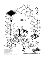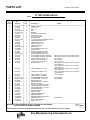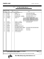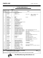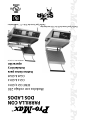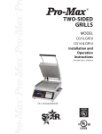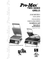
1
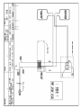
®
®
TWO-SIDED
GRILLS
230V MODELS
®
CG10, GR10
CG14 & GR14
CG28 & GR28 SERIES
Installation and
Operation
Instructions
®
2M-Z8985 Rev. C 8/01/07
35.6 CM X 35.6 CM Grooved Grill
35.6 CM X 71.1 CM Grooved Grill
1
SAFETY SYMBOL
These symbols are intended to alert the user to the presence of
important operating and maintenance instructions in the manual
accompanying the appliance.
RETAIN THIS MANUAL FOR FUTURE REFERENCE
NOTICE
Using any part other than genuine Star factory supplied parts relieves the
manufacturer of all liability.
Star reserves the right to change specifications and product design without
notice. Such revisions do not entitle the buyer to corresponding changes,
improvements, additions or replacements for previously purchased
equipment.
Due to periodic changes in designs, methods, procedures, policies and
regulations, the specifications contained in this sheet are subject to change
without notice. While Star Manufacturing exercises good faith efforts to provide
information that is accurate, we are not responsible for errors or omissions
in information provided or conclusions reached as a result of using the
specifications. By using the information provided, the user assumes all risks in
connection with such use.
MAINTENANCE AND REPAIRS
Contact your local dealer for service or required maintenance. Please record the model number, serial
number, voltage and purchase date in the area below and have it ready when you call to ensure a faster
service.
Model No.
Serial No.
Voltage
Purchase Date
2
2
PRODUCT IDENTIFICATION
Star Manufacturing International, Inc. Two Sided Grills
230V Models:
GR10-230V- Smooth Top and Bottom Platens Aluminum, without Timer
GR10T-230V- Smooth Top and Bottom Platens Aluminum, with Timer
GR10I-230V- Smooth Top and Bottom Platens Cast Iron, without Timer
GR10IT-230V- Smooth Top and Bottom Platens Cast Iron, with Timer
CG10I-230V- Grooved Top and Bottom Platens Cast Iron, without Timer
CG10IT-230V-Grooved Top and Bottom Platens Cast Iron, with Timer
GR14-230V- Aluminum Smooth Top and Bottom Platens, without Timer
GR14T-230V- Aluminum Smooth Top and Bottom Platens, with Timer
GR14I-230V- Iron Smooth Top and Bottom Platens, without Timer
GR14IT-230V- Iron Smooth Top and Bottom Platens, with Timer
CG14-230V- Aluminum Grooved Top and Bottom Platens, without Timer
CG14T-230V- Aluminum Grooved Top and Bottom Platens, with Timer
CG14I-230V-Iron Grooved Top and Bottom Platens, without Timer
CG14IT-230V- Iron Grooved Top and Bottom Platens, with Timer
CG28I-230V Grooved Iron Platens without Timers
CG28IT-240V Grooved Iron Platens with 2 Timers
CG28IGT-240V Iron Platens, Grooved Top and Smooth Bottom without Timers
GR28I-240V Smooth Iron Platens without Timers
GR28IT-240V Smooth Iron Platens with 2 Timers
3
GENERAL INSTALLATION DATA
CAUTION
This equipment is designed and sold for
commercial use only by personnel trained and
experienced in its operation and is not sold for
consumer use in and around the home nor for
use directly by the general public in food service
locations.
Before using your new equipment, read
and understand all the instructions & labels
associated with the unit prior to putting it into
operation. Make sure all people associated with
its use understand the units operation & safety
before they use the unit.
All shipping containers should be checked for
freight damage both visible and concealed. This
unit has been tested and carefully packaged to
insure delivery of your unit in perfect condition.
If equipment is received in damaged condition,
either apparent or concealed, a claim must be
made with the delivering carrier.
Concealed damage or loss - if damage or loss is
not apparent until after equipment is unpacked, a
request for inspection of concealed damage must
be made with carrier within 15 days. Be certain
to retain all contents plus external and internal
packaging materials for inspection. The carrier
will make an inspection and will supply necessary
claim forms.
VENTILATION AND CLEARANCES
The installation of any components such as
a vent hood, grease extractors, and/or fire
extinguishing systems, must conform to their
applicable nationally recognized installation
standards and/or local building codes.
ELECTRICAL CONNECTION
CAUTION
Before making any electrical connection be sure
to read data plate which is located at the bottom
of the unit.
ELECTRICAL GROUNDING
INSTRUCTIONS
This unit is equipped with a CEE-7/VII Cord, use
the proper (grounding) plug that provides proper
protection against shock hazard and must be
plugged directly into a properly grounded 3-prong
receptacle. For your protection we recommend
that a qualified electrician be consulted in regards
to any electrical conserns or installations. He/she
should be familiar with electrical installations and
all electric codes. Proper connections and power
supply are essential for efficient performance.
CAUTION
DO NOT CUT OR REMOVE THIS PLUG OR
GROUNDING PRONG FROM THE PLUG.
CAUTION
CONNECT/PLUG UNIT INTO DEDICATED
A.C LINE ONLY SPECIFIED ON THE DATA
PLATE OF THE UNIT.
4
Model No.
Volts
GR 10
GR 10I
CG 10I
GR 14
GR 14I
CG 14
CG 14I
CG 28I
GR 28I
230
230
230
230
230
230
230
230
230
ELECTRICAL SPECIFICATIONS
Rated Wattage
1653
1653
1653
1653
3306
1653
3306
6612
6612
INITIAL START UP
Level unit using the adjustable feet under the unit
(approximately 1/2" adjustment).
Before using the unit for the first time, clean and
heat for approximately 30 minutes. The grill may
emit a small amount of smoke as the cooking
surfaces reach 300-350°F (148-176°C). Do
not be alarmed, as the smoke is caused by oils
associated with the manufacturing process and
will stop when the grill reaches 400°F (204°C).
This will take approximately 30 minutes. Brush
off any debris from the grilling surfaces. Allow
grill to cool prior to placing it in its permanent
position.
SEASONING THE COOKING SURFACES
Amps
7.2
7.2
7.2
7.2
14.2
7.2
14.2
28.7
28.7
NEMA Plug
CEE-7/VII
CEE-7/VII
CEE-7/VII
CEE-7/VII
CEE-7/VII
CEE-7/VII
CEE-7/VII
CEE-7/VII
CEE-7/VII
SETTING THE TEMPERATURE
The thermostat control knob is used to set the
temperature to your requirements. The maximum
set point is 550°F (288°C), the minimum set point
is 175°F (79°C). See Knob Settings.
SETTING THE TIMER (TIMER MODELS ONLY)
(9 MIN. 59 SEC. MAX)
The timer may be factory pre-set. If changes are
required follow these simple steps:
1. To increase time, press and hold the
(UP) button. The Start/Stop button can
now be used to increase the cooking time.
2. To decrease time, press and hold the
(DOWN) button. The Start/Stop button
can now be used to decrease cooking time.
KNOB SETTING
FIRST TIME SEASONING
Knob Position
Follow your company/corporate guidlines for
seasoning cooking surfaces. or
1-2
3
4
5
6
7
8
9
10
1. Bring the grill to 300°F and leave it on while
doing the next three steps.
2. Brush the cooking surfaces with a release
agent. If using an aerosol agent,
first apply into a cup and then brush onto
cooking surface.
3. Let sit for 20 minutes, and then wipe clean
using a warm damp cloth.
DAILY SEASONING
The grill should not require much seasoning while
in use. In most cases, brush a light coating of the
baking release agent in the morning and occasionally
throughtout the day will be enough to prevent any
sticking. It is not necessary to spray before grilling
each item.
5
Approx. Temp
175°F / 79°C
200°F / 93°C
250°F / 121°C
300°F / 148°C
350°F / 176°C
400°F / 204°C
450°F / 232°C
500°F / 260°C
550°F / 287°C
ON/OFF ROCKER SWITCH
(TIMER MODELS ONLY)
The switch turns the unit on and off. The switch
has three positions:
With the switch in this position,
both top and bottom platens
will heat.
With the switch in this position,
neither platen will heat.
With the switch in this position
only bottom platen will heat.
DAILY OPERATION
Always allow 10-20 minutes of preheat time
before loading the unit with product. Failure
to allow sufficient preheat time will result in
unsatisfactory cooking of the first load.
Check the power cord to insure that it is plugged
into a proper outlet.
Check that the switch and thermostat control are
turned on.
Set the unit's ON/OFF rocker switch to desired
position.
Set the thermostat control knob to desired
temperature.
OPERATING HINTS AND SAFETY
MONTHLY LUBRICATION/INSPECTION
Apply two (2) drops of non-toxic mineral or
vegetable oil to counter balance shoulder rivets
and plastic spacers.
Check and clean brass rollers to make sure they
are rolling and not sliding on the cam surfaces of
the counterbalance.
Check the bolts, screws and nuts, tighten if
necessary.
CLEANING
Begin cleaning procedure by using the operating
procedures within your organization, or follow the
steps below:
1. If particles adhere to the cooking surface during
the day, scrape them off with a spatula.
NOTE: It is best not to let food cook onto the
grill, as food build-up on the grill will increase
sticking and smoking. In addition, carbon may
build up on the grill surface and reduce the
cooking efficiency.
CARBON BUILDUP: A black matter that forms on
or near the cooking surface. Generally this is
releasing agents that has cooked itself to the
surface. After a period of time, without carbon
cleaning this material may start flaking off. When
that happens, follow the "Carbon Cleaning"
procedures.
2. At the end of the day, wipe down all surfaces
with a warm, damp cloth and mild detergent,
then dry.
Disconnect power to the unit with the switch at
the end of each day of operation.
CAUTION
Do not leave the unit in operation without an
attendant.
Turn thermostat down to 200°F (93°C) during idle
periods. It will take only a few minutes to regain
operating temperature.
DO NOT IMMERSE OR LET THE UNIT
STAND IN WATER.
Use spatula to push excess grease into grease
drawer after each load of food is cooked.
This will reduce smoking of hot grease and
carbonizing.
DO NOT HOSE DOWN THE UNIT OR
THE TABLE/COUNTER IF THE UNIT IS
ON THE TABLE/COUNTER.
Do not leave the unit at high temperature when
not in use or during idle periods. This will cause
food particles and grease film to carbonize.
KEEP AWAY FROM RUNNING WATER.
"Season" cooking surfaces with non-salted
vegetable oil to reduce product sticking.
6
CLEANING CON'T
OPERATION TROUBLESHOOTING
CAUTION
DO NOT USE SHARP OBJECTS TO REMOVE
CARBON BUILD-UP.
BEFORE CLEANING MAKE SURE POWER IS
TURNED OFF, UNIT IS UNPLUGGED AND IS
NOT TOO HOT.
While holding top lid with one hand, apply
only cleaners which are safe for aluminum
and iron surfaces. Wipe with clean sponge or
towel until unit is clean.
DO NOT SPLASH FRONT CONTROL
PANEL!
DO NOT SPLASH FLEX CONDUIT
CONNECTING TOP AND BOTTOM
OF THE UNIT.
1. Unit not heating.
A. Check if unit is plugged in correct
receptacle.
B. Check incoming power line.
C. Check that the switch is in correct position.
D. Check that thermostat is set to proper
temperature.
2. Top platen not heating.
A. Check that the rocker switch is in correct
postion.
3. Counter balance roller not rolling.
A. Clean rollers.
If unit still does not operate contact the factory
or one of its representatives or a local service
company for service or required maintenance.
Remove and empty to clean grease catcher drawer
as required using mild detergent and water.
WARNING
Do not use ice or cold water to clean the cooking
surfaces when the unit is hot. The surfaces are
cast aluminum or cast iron and may crack or deform
under the shock of rapid temperature change.
CARBON CLEANING
When carabon build up occurs, use a carbon removal
agent according to the instructions provided with
the cleaner. When this process is complete, you
must re-season the grill according to your company/
corporate guidlines, or the seasoning instructions
in this manual.
7
INTERNATIONAL ONE (1) YEAR EQUIPMENT WARRANTY
All workmanship and materials in “STAR” products are warranted for a period of one year from the date shipped from the factory or
one year from the date shown on the proof of purchase of the end-user when purchased through an authorized “STAR” dealer/distributor in a commercial foodservice location.
“STAR’s” obligation under this warranty is limited to the replacement of the defective part(s) only without charge. This warranty is
void if damage occurs from improper installation, misuse or abuse, disassembly or tampering of unit for any purpose other than repair
by a qualified service agent, wrong voltage, incorrect or fluctuating voltage conditions, wrong gas, improper gas or gas conditions,
operated contrary to the installation and operating instructions, operated in an application for which the unit is not suited, or if the unit
is not maintained and/or cleaned in a suitable manner.
Any expense in connection with installation, or any cost of making adjustments on a unit to conform to electric or gas service at the
point of installation, are not covered by this warranty.
* The warranty period for the JetStar series six (6) ounce popcorn machines is two (2) years.
* The warranty period for the Chrome-Max Griddles is five (5) years on the griddle surface. See detailed warranty provided with unit.
* The warranty period for Teflon/Dura-Tec coatings is one year under normal use and reasonable care. This warranty does not
apply if damage occurs to Teflon/Dura-Tec coatings from improper cleaning, maintenance, use of metallic utensils, or abrasive
cleaners. This warranty does not apply to the “non-stick” properties of such materials.
* This warranty is not valid on Conveyor Ovens unless a “start-up/check-out has been performed by a Factory Authorized Technician.
In order to make a claim under this warranty; a warranty report must be filed with Star Manufacturing International Inc. in St. Louis,
Missouri, U.S.A. by the dealer/distibutor through which product was purchased. All details, including serial number and model number of the defective unit, must be included. Failure to file a claim within a 120 Day time period may result in the claim being refused.
“STAR” may forego the necessity of returning the part for inspection dependent upon the expense involved. However, “STAR”
requires defective parts to be held in the claimant’s possession for a period of ninety (90) days for possible inspection by a “STAR”
representative or designated inspector .
The foregoing warranty is lieu of any and all other warranties, expressed or implied, and constitutes the entire warranty.
PARTS WARRANTY
Parts that are sold for out-of-warranty repair are warranted for a period of ninety days. The part only is warranted; no labor.
SERVICES NOT COVERED BY WARRANTY
1.
2.
3.
4.
5.
6.
7.
8.
9.
10.
11.
12.
13.
14.
15.
16.
Labor
Mileage and/or travel time
Installation and/or adjustment of equipment
Operation contrary to the installation and operating instructions
Cleaning of equipment
Seasoning of griddle plates
Voltage conversions/adjustments
Gas conversions
Pilot light conversion/adjustments
Thermostat calibration/adjustments
Resetting of circuit breakers or safety controls
Replacement of bulbs/lamps
Replacement of fuses
Damages due to improper installation
Damages from abuse or misuse
Damage created by acts of God, Acts of War, or Civil Disturbance
08-05 rms
8
9
10
11
TOP ELEMENT
15 AMP PLUG
NEMA 5-15P ON ALL 120V UNITS.
NEMA 6-15P ON 240V, 1,800 WATT UNITS.
20 AMP PLUG
NEMA 6-20P ON 240V, 3,600 WATT UNITS.
GREEN
INLET IEC 320 16A
WHITE
BLACK
TERMINAL BLOCK
TRANSFORMER
G
L
N
20
9
18
10
8
1
19
6
8
6
4
2
7
13
5
230V UNITS
BOTTOM ELEMENT
THERMOSTAT
9
3
7
3
INDICATOR LIGHT
(POWER ON)
10
12
13
E2 E1
11
12
3
2
4
11
5
1
SWITCH
TIMER BOARD
FOR REFERENCE
WIRING DIAGRAM IS SHOWN AS UNIT IS ASSEMBLED
WITH THE BOTTOM PLATE REMOVED. ITEMS ARE IN
GENERAL LOCATION BUT MAY BE RELOCATED OR SCALED
FOR CLARITY.
MODEL: CG/GR, 10/14, 120V/230/240V,
WITH TIMER
THIS DRAWING CONTAINS INFORMATION CONFIDENTIAL TO STAR MFG. INT'L. INC.
NO REPRODUCTION OR DISCLOSURE OF ITS CONTENTS IS PERMITTED.
STAR MANUFACTURING INTERNATIONAL INC.
SK2001
12
Rev A
8/10/2004
DATE
-
SWITCH
(INTERRUPTOR)
2
1
T-STAT
TERM BLOCK
(BLOQUE TERMINAL)
BLACK
(NEGRO)
3
5
4
7
4)-%
9
34/0
34!24
TRANS
6
10
-
11
12
BOTTOM ELEMENT
(ELEMENTO MAS BAJO)
TOP ELEMENT
(ELEMENTO MAS ALTO)
NEMA 6-30 P PLUG
4
2,5
1,8
3,6,7
10
9
11
12
WIRE NO
(HILO NO.)
BOTTOM ELEMENT
(ELEMENTO MAS BAJO)
1
1
1
1
1
1
1
1
QTY.
(CANTIDAD)
TOP ELEMENT
(ELEMENTO MAS ALTO)
D9-GR0058
D9-GR0059
D9-GR0060
D9-GR0064
D9-GR0057
D9-GR0065
D9-GR0106
D9-GR0107
PART NO.
(PARTE NO.)
10 SUNNEN DRIVE ST. LOUIS, MO 63143
STAR MFG. INTERNATIONAL, INC.
FINISH
FRONT CONTROL PANEL
TIMER
REAR PANEL
8
7-05-99
WHITE
(BLANCO)
GREEN
(VERDE)
LIMITS UNLESS OTHERWISE NOTED
FRACTIONS 1/64 DECIMALS .005
DR. TSCK.
MATERIAL
SK-1709
PART NO.
FRONT CONTROL PANEL
TIMER
REAR PANEL
8
10
6
0/43
42!43
%-)4
9
7
4
5
3
T-STAT
1
2
SWITCH
(INTERRUPTOR)
TERM BLOCK
(BLOQUE TERMINAL)
TITLE WIRE DIAGRAM 240V 7200W UL W/TIMER
MODEL NO.
GR/CG28IT-240V
CG28ITGT-240V
TRANS
13
14
2
3
20
FRONT CONTROL PANEL
REAR PANEL
TERM BLOCK
(BLOQUE TERMINAL)
L
N
G
NEMA L6-30 P PLUG
NO REPRODUCTION OR DISCLOSURE OF ITS CONTENTS IS PERMITTED.
15
14
240V UNITS
230V UNITS
INLET IEC 320 16A
THIS DRAWING CONTAINS INFORMATION CONFIDENTIAL TO STAR MFG. INT'L. INC.
MODEL: GR-CG28I-230/240V
PILOT
LIGHT
T-STAT
1
WHITE
(BLANCO)
BLACK
(NEGRO)
GREEN
(VERDE)
18
19
BOTTOM ELEMENT
(ELEMENTO MAS BAJO)
TOP ELEMENT
(ELEMENTO MAS ALTO)
1
1
1
1
1
QTY.
(CANTIDAD)
1
1
1
1
1
1
2
2
2
QTY.
(CANTIDAD)
BOTTOM ELEMENT
(ELEMENTO MAS BAJO)
TOP ELEMENT
(ELEMENTO MAS ALTO)
1 D9-GR0103
2 D9-GR0104
3 D9-GR0105
14 D9-GR0106
15 D9-GR0107
WIRE NO PART NO.
(HILO NO.) (PARTE NO.)
4 D9-GR0058
2,5 D9-GR0059
1,8 D9-GR0060
3,6,7 D9-GR0064
10 D9-GR0057
9 D9-GR0065
18 D9-GR0250
19 D9-GR0251
20 D9-GR0252
WIRE NO PART NO.
(HILO NO.) (PARTE NO.)
TERM BLOCK
(BLOQUE TERMINAL)
FRONT CONTROL PANEL
REAR PANEL
G
N 18
PILOT
LIGHT
T-STAT
2
3
SK1710
Rev B
8/09/2004
STAR MANUFACTURING INTERNATIONAL INC.
INLET IEC 320 16A
20
L
19
1
4
5
3
11
2
10
6
1
7
8
12
13
54
53
9
52
14
54
PR
EC
Favo
o
GR
SUP NO
TOC
CAL ERI
AR
IEN FIC
IE
TE
ient
e
ia
gu
no
la
sobr
CI
sum
base
e
ergi
r
ON
este
agua
con
er
a.
ase
de
que
ncad
a
roc
an
LI
AU
rde
dejar
esta
No
m
Main
teng
corr
PE
FAV
OR
lejos
de
agu
a.
O
Do
CAU
not
imm
erse
base
Do
stan
hos
T
GE
R
NO
T
run p
nin away
g
from
wat
er.
e
dow
n.
in
24
TIO
or
d
not
Kee
DAN
DO
HO
N
let
wate
r.
15
SU TOU
RFA CH
CE
.
51
16
16
28
27
17
29
18
19
17
30
20
50
26
25
21
19
55
31
49
22
32
48
47
43
33
44
34
45
39
46
TO
P
BO &
ON TTOM
(I)
PO
BO
TTO
ON M
WER
OF
F
PO
WER
23
42
ON
PR
OMA
X
41
TIM
E
40
35
STAR
T
STOP
37
SOME ITEMS ARE INCLUDED FOR
ILLUSTRATIVE PURPOSES ONLY AND IN
CERTAIN INSTANCES MAY NOT BE AVAILABLE
38
This drawing contains information confidential
to Star Manufacturing International, Inc.
No reproduction or disclosure of its
contents is permitted.
MODEL GR10I,CG10I,
GR14,GR14I,CG14,CG14I,CG14IGT
STAR MANUFACTURING INTERNATIONAL, INC.
SK1687
15
REV. C
10/13/05
PARTS LIST
August 1, 2007, Rev C
MODEL
Key
Number
Part
Number
Number
Per
Unit
10' TWO SIDED GRILLS
Description
Model
1
2
3
4
4
5
6
7
8
9
10
11
12
13
14
15
16
17
18
19
20
20
21
21
21
22
2C-Z2992
2V-Z2990
2B-Z2988
2C-08-07-0040
2C-08-07-0262
2C-Z2992
D9-Z2038
2C-Z3200
2C-Z2855
2C-08-07-0040
24-Z3827
2C-Z3780
2E-Z2898
2E-Z3768
D9-04-GR-0166
D9-GR0084
D9-Z2908
2A-Z6604
D9-Z2772
2C-08-07-0285
2N-Z1978
2N-Z2019
2F-Z1928
2F-Z1932
2F-Z1934
2K-Y3240
2
1
2
4
4
4
1
2
2
2
1
2
1
1
1
1
2
8
1
8
1
1
1
1
1
1
SCREW, HANDLE
HANDLE - 10”
ARM - 10”
NUT
WASHER
SCREW, ARM TO BRACKET
HOUSING-TOP-10”
PIN - TOP HOUSING
RETAINER RING
1/4” NUT, USE PART NUMBER 2C-Z2820
CONDUIT KEEPER PLATE
CONDUIT RETAINER
CONDUIT ASSY. - PTFE
CONDUIT LOCKNUT
WIRE MOUNT
TOP RETAINING PLATE AY/10
INSULATION - 10”
SPACER - INSULATED PLATE
TOP ELEMENT/INS. PLATE/10
SCREW, ELEMENT RET. PLATE
TOP ELEMENT, HEATING, 800W/120
TOP ELEMENT, HEATING, 800W/240V
CASTING, SM. TOP,ALUM.-10”
CASTING, SM. TOP, IRON-10”
CASTING, GR. TOP, IRON-10”
BUSHING 90 SR 17-2
23
2E-Z2770
1
CORD, POWER, 14-3, 6-15P
2E-Z2935
1
CORD SET 14/3 NEMA 5-15P
2E-Z4119
2M-Z2620
2E-05-07-0350
2E-05-07-0351
2E-Z2894
D9-GR0053
2C-1512
2V-Z3252
2R-Z2907
2R-Z3333
D9-GR0032
D9-Z3071
2V-Z3072
D9-GR0034
D9-Z2527
D9-GR0082
D9-GR0246
2A-Z1485
D9-GR0062
1
1
1
1
1
1
2
1
1
1
2
4
2
1
1
1
1
4
1
CORD, POWER, 12/3 5-20P
LABEL CAUTION, BI-LINGUAL
TRANSFORMER 230V/10V 6VA
TRANSFORMER 115/10V 6VA
TERMINAL BLOCK
REAR LINER ASSY. - 10”/BOT
SCREW - PIN ASSY
PIN ASSY - TOP HOUSING STOP
COUNTERBALANCE -10”-IRON
COUNTERBALANCE -10”-ALUM.
TORQUE BOX ASSY.
BRACKET-HANDLE
HANDLE - SIDE
GREASE CABINET ASSY.
GREASE DRAWER
GREASE DRAWER FRONT ASSY.
BASE BOTTOM - 10”
FOOT, 1” ADJUSTABLE
BODY ASSY. - 10”
24
25
25
26
27
28
29
30
30
31
32
33
34
35
36
37
38
39
GR10I, GR10IT, CG10I, CG10IT, GR10, GR10T
GR10I, GR10IT, CG10I, CG10IT, GR10, GR10T
GR10, GR10T
GR10I, GR10IT
CG10I, CG10IT
GR10, GR10T, GR10I, GR10IT, CG10I, CG10IT,
(120V MODELS),
GR10, GR10T, GR10I, GR10IT, CG10I,CG10IT
(240V MODELS)
GR10T, GR10, GR10I, GR10IT, CG10I, CG10IT,
(240V MODELS)
GR10T, GR10, GR10I, GR10IT, CG10I, CG10IT,
(120V MODELS)
120VC MODELS
240V MODELS
120V MODELS
230V MODELS
IMPORTANT: WHEN ORDERING, SPECIFY VOLTAGE OR TYPE DESIRED
INCLUDE MODEL AND SERIAL NUMBER
Some items are included for illustrative purposes only and in certain instances may not be available.
Star Manufacturing International, Inc.
16
PAGE 1
OF
2
PARTS LIST
August 1, 2007, Rev C
MODEL
Key
Number
Part
Number
Number
Per
Unit
40
41
42
42
43
43
44
44
2J-Z1836
2K-Z1971
2J-Y6689
2J-Z2329
D9-GR0051
D9-GR0109
2E-Z6863
PS-GR0223
1
4
1
1
1
1
1
1
45
45
46
47
48
49
50
51
52
52
53
53
53
54
55
2M-Z6881
2M-Z3051
2I-05-07-0013
2R-Z1854
2T-6447
2A-Z3026
D9-Z2774
D9-Z2773
2N-Z1979
2N-Z2020
2F-Z1929
2F-Z1933
2F-Z1935
2C-Z5883
PS-GR134
1
1
1
1
1
1
1
1
1
1
1
1
1
8
2
10' TWO SIDED GRILLS
Description
Model
TIMER CONTROL
CG10T, CG10IT, GR10T, GR10IT
SPACER
CG10T, CG10IT, GR10T, GR10IT
PILOT LIGHT, 120V
GR10, GR10I, CG10I (120V MODELS)
PILOT LIGHT, 240V
GR10, GR10I, CG10I (240V MODELS)
FACEPLATE ASSY. - 10” w/TIMER
GR10T, GR10IT, CG10IT
FACEPLATE ASSY. - 10” NO TIMER
GR10, GR10I, GR10I, CG10I, CG10I
SWITCH 3 POS
CG10T, CG10IT, GR10T, GR10IT
SWITCH
CG10IT-120V W/SERIAL NUMBERS BELOW CGA24279
CG10IT-240V W/SERIAL NUMBERS BELOW CGA20294
GR10IT-120V W/SERIAL NUMBERS BELOW GRA27109
CG10TJD-240V W/SERIAL NUMBERS BELOW CGA29997
GR10T-240V W/SERIAL NUMBERS BELOW GRA03390
OVERLAY - 10” w/TIMER
GR10T, GR10IT, CG10IT
OVERLAY - 10” NO TIMER
GR10, GR10I, CG10I
RUBBER BOOT, SWITCH
KNOB-CONTROL
THERMOSTAT 118V-236V
HALF CLIP
BTM. INSULATION RET. PLT. 10”
BTM ELEMENT RET. PLATE 10”
BTM ELEMENT, HEATING, 1000W/120
GR10I, GR10IT, CG10I, CG10IT, GR10, GR10T
BTM ELEMENT, HEATING, 1000W/240
GR10I, GR10IT, CG10I, CG10IT, GR10, GR10T
CASTING, SM.BOT., ALUM.-10”
GR10, GR10T
CASTING, SM. BOT., IRON-10”
GR10I, GR10IT
CASTING, GR. BOT., IRON-10”
CG10I, CG10IT
SCREW 10-24X1/2 FZA
ROLLER BEARING KIT
IMPORTANT: WHEN ORDERING, SPECIFY VOLTAGE OR TYPE DESIRED
INCLUDE MODEL AND SERIAL NUMBER
Some items are included for illustrative purposes only and in certain instances may not be available.
Star Manufacturing International, Inc.
17
PAGE 2
OF 2
PARTS LIST
August 1, 2007, Rev C
MODEL
14' TWO SIDED GRILLS
Part
Number
Number
Per
Unit
1
2
2
2C-Z2992
2V-Z2989
2V-Z3413
2
1
1
SCREW, HANDLE
HANDLE - 14”
HANDLE - 14” S.S.
3
3
4
4
5
6
7
8
9
10
11
12
13
14
15
16
17
18
19
20
20
20
21
21
21
21
22
2B-Z2987
2B-Z3336
2C-08-07-0040
2C-08-07-0262
2C-Z2992
D9-Z2036
2C-Z3200
2C-Z2955
2C-08-07-0040
2A-Z3827
2C-Z3780
2E-Z2898
2E-Z3768
D9-04-GR-0166
D9-GR0079
D9-Z2888
2A-Z6604
D9-Z2075
2C-08-07-0285
2N-Z1980
2N-Z2021
2N-Z2391
2F-Z7786
2F-Z1946
2F-Z1948
2F-Z1950
2K-3485
2
2
4
4
4
1
2
2
2
1
2
1
1
1
1
2
8
1
8
1
1
1
1
1
1
1
1
ARM - 14”
ARM
NUT
WASHER
SCREW, ARM TO BRACKET
HOUSING-TOP-14”
PIN - TOP HOUSING
RETAINER RING
1/4” NUT, USE PART NUMBER 2C-Z2820
CONDUIT KEEPER PLATE
CONDUIT RETAINER
CONDUIT ASSY. - PTFE
CONDUIT LOCKNUT
WIRE MOUNT
TOP RETAINING PLATE AY/14
INSULATION - 14”
SPACER - INSULATED PLATE
TOP ELEMENT/INS. PLATE/14
SCREW, ELEMENT RET. PLATE
TOP ELEMENT, HEATING, 800W/120
TOP ELEMENT, HEATING, 800W/240V
TOP ELEMENT, HEATING, 1800W/240
CASTING, SM. TOP, ALUM.-14”
CASTING, GR. TOP, ALUM.-14”
CASTING, SM. TOP, IRON-14”
CASTING, GR. TOP, IRON-14”
BUSHING-HEYCO #SR-9P-2
2K-Y2968
2K-Y6764
2K-Y3240
1
1
1
BUSHING 7W-2
BUSHING
BUSHING
23
2E-Z2905
1
CORD SJTO 12/2 NEMA 6-20P
24
25
25
26
27
27
27
28
29
30
30
2E-Z2935
2E-Z4119
2M-Z2620
2E-05-07-0350
2E-05-07-0351
2E-Z2894
D9-GR0054
D9-GR0080
D9-GR0201
2C-1512
2V-Z3252
2R-Z2896
2R-Z2897
1
1
1
1
1
1
1
1
1
2
1
1
1
CORD SET 14/3 NEMA 5-15P
CORD, POWER 12/3 5-20P
LABEL CAUTION, BI-LINGUAL
TRANSFORMER 230V/10V 6VA
TRANSFORMER 115/10V 6VA
TERMINAL BLOCK
REAR LINER ASSY. - 14”/BOT
REAR LINER ASSY. - 14”/REAR
REAR LINER ASSY.
SCREW - PIN ASSY
PIN ASSY - TOP HOUSING STOP
COUNTERBALANCE -14”-IRON
COUNTERBALANCE -14”-ALUM.
Key
Number
Description
Model
GR14, GR14T
SER. # GRC00112 - 00138,
GRC00778 - 00858,
GRC00864 - 01256
GR14SN
CG14, CG14T, GR14, GR14T, CG14IT-120V
CG14, CG14T, GR14, GR14T
GR14I, GR14IT, CG14IGT, CG14ITGT, CG14I, CG14IT
GR14, GR14T
CG14, CG14T
GR14I, GR14IT
CG14IGT, CG14ITGT
GR14I, GR14IT, CG14IGT, CG14ITGT, CG14I,
CG14IT (240V MODELS)
CG14IT-120V
CG14IT-120VC (CANADIAN)
CG14, CG14FT, CG14T, GR14, GR14SN,
GR14T, (120V &120VC)
GR14I, GR14IT, CG14IGT, CG14ITGT, CG14I,
CG14IT (240V MODELS)
120V MODELS
120VC (CANADIAN) MODELS
240V MODELS
120V MODELS
CG14, GR14, CG14T, GR14T
CG14I, GR14I, CG14IGT, CG14IT, GR14IT, CG14ITGT
CG14IT (120V)
IMPORTANT: WHEN ORDERING, SPECIFY VOLTAGE OR TYPE DESIRED
INCLUDE MODEL AND SERIAL NUMBER
Some items are included for illustrative purposes only and in certain instances may not be available.
Star Manufacturing International, Inc.
18
PAGE 1
OF 2
PARTS LIST
August 1, 2007, Rev C
MODEL
Key
Number
Part
Number
Number
Per
Unit
31
32
33
34
35
36
37
38
38
39
39
40
41
42
42
43
43
43
44
44
D9-GR0032
D9-Z3071
2V-Z3072
D9-GR0034
D9-Z2527
D9-GR0082
D9-GR0247
2A-Z0314
2A-Z1485
D9-GR0061
D9-GR0184
2J-Z1836
2K-Z1971
2J-Y6689
2J-Z2329
D9-GR0108
D9-GR0178
D9-GR0210
2E-Z6863
PS-GR0224
2
4
2
1
1
1
1
4
4
1
1
1
4
1
1
1
1
1
1
1
45
45
45
46
47
48
49
50
51
52
52
52
53
53
53
53
54
55
NI
NI
NI
NI
NI
NI
NI
NI
2M-Z6870
2M-Z3050
2M-Z3816
2I-05-07-0013
2R-Z1854
2T-6447
2A-Z3026
D9-Z8082
D9-Z8082
2N-Z1981
2N-Z2022
2N-Z2392
2F-Z1945
2F-Z1947
2F-Z1949
2F-Z1951
2C-Z5883
PS-GR134
2C-08-WB-0008
2C-09-WB-0005
2P-09-WB-0007
2P-Z2911
2R-09-WB-0006
2V-Z3027
D9-Z3028
D9-Z3029
1
1
1
1
1
1
1
1
1
1
1
1
1
1
1
1
8
2
2
2
2
1
2
2
1
1
14' TWO SIDED GRILLS
Description
Model
TORQUE BOX ASSY.
BRACKET-HANDLE
HANDLE - SIDE
GREASE CABINET ASSY.
GREASE DRAWER
GREASE DRAWER FRONT ASSY.
BASE BOTTOM - 14”
230V MODELS
FOOT, 4”
GR14I, GR14IT, CG14I, CG14IT, CG14IGT, CG14ITGT
FOOT, 1” ADJUSTABLE
BODY ASSY. - 14”
BODY ASSY
GR14SN
TIMER CONTROL
CG14T, CG14IT, CG14IGT, GR14T, GR14IT
SPACER
CG14T, CG14IT, CG14IGT, GR14T, GR14IT
PILOT LIGHT, 120V
CG14, GR14 (120V MODELS)
PILOT LIGHT, 240V
GR14I, CG14IGT, CG14I, CG14, GR14 (240V MODELS)
FACEPLATE ASSY. - 14” NO TIMER
GR14I, CG14IGT, CG14I, CG14, GR14
FACEPLATE ASSY. - 14” 2 TIMERS
CG14-2T
FACEPLATE ASSY. - 14” w/TIMER
GR14IT, CG14ITGT, CG14IT, CG14T, GR14T
SWITCH 3 POS
CG14T, CG14IT, CG14IGT, GR14T, GR14IT
SWITCH
CG14T-120V W/SERIAL NUMBERS BELOW CGC25308
CG14IT-120V W/SERIAL NUMBERS BELOW CGC24701
GR14T-120V W/SERIAL NUMBERS BELOW GRC23789
CG14IT-240V W/SERIAL NUMBERS BELOW CGC24559
OVERLAY - 14” w/TIMER
GR14IT, CG14ITGT, CG14IT, CG14T, GR14T
OVERLAY - 14” NO TIMER
GR14I, CG14IGT, CG14I, CG14, GR14
OVERLAY - 14” w/2 MANUAL TIMERS
CG14-2T
RUBBER BOOT, SWITCH
KNOB-CONTROL
THERMOSTAT 118V-236V
HALF CLIP
BTM. INSULATION RET. PLT. 14”
BTM ELEMENT RET. PLATE 14”
BTM ELEMENT, HEATING, 1000W/120
CG14, CG14T, GR14, GR14T, CG14IT-120V
BTM ELEMENT, HEATING, 1000W/240
CG14, CG14T, GR14, GR14T
BTM ELEMENT, HEATING, 1800W/240V GR14I, GR14IT, CG14IGT, CG14ITGT, CG14I, CG14IT
CASTING, SM. BOT., ALUM.-14”
GR14, GR14T
CASTING, GR. BOT., ALUM.-14”
CG14, CG14T
CASTING, SM. BOT., IRON-14”
GR14I, GR14IT, CG14IGT, CG14ITGT
CASTING, GR. BOT., IRON-14”
CG14I, CG14IT
SCREW 10-24X1/2 FZA
ROLLER BEARING KIT
NUT-TIMER (NOT SHOWN)
CG14-2T
BEZEL (NOT SHOWN)
CG14-2T
TIMER BELL (NOT SHOWN)
CG14-2T
PLUG DOUBLE D .75x.625
CG14I, GR14I, CG14IGT, CG14IT, GR14IT, CG14ITGT
KNOB-BLACK (NOT SHOWN)
CG14-2T
CROSS SUPPORT (NOT SHOWN)
GR14I, GR14IT, CG14I, CG14IT, CG14IGT, CG14ITGT
SIDE SUPPORT (NOT SHOWN)
GR14I, GR14IT, CG14I, CG14IT, CG14IGT, CG14ITGT
PART SUPPORT (NOT SHOWN)
GR14I, GR14IT, CG14I, CG14IT, CG14IGT, CG14ITGT
IMPORTANT: WHEN ORDERING, SPECIFY VOLTAGE OR TYPE DESIRED
INCLUDE MODEL AND SERIAL NUMBER
Some items are included for illustrative purposes only and in certain instances may not be available.
Star Manufacturing International, Inc.
19
PAGE 2
OF 2
20
46
39
40
41
42
43
38
(O
ER
OFF
POW
)
ON
(I)
ax
-M
Pro
TIME
START
STOP
11
36
37
43A
10
STOP
START
TIME
31
POW
(O
ER
OFF
)
ON
(I)
35
NO REPRODUCTION OR DISCLOSURE OF ITS CONTENTS IS PERMITTED.
THIS DRAWING CONTAINS INFORMATION CONFIDENTIAL TO STAR MFG. INT'L. INC.
MODEL:GR28I,CG28I,CG28IGT-240V
44
45
47
1A
1
2
2A
48
26
18
8
7
2B
3
25
o
dejar
Favor
este
rgir
agua
base
sume
PRE
CAU
9
.
con
era
rocia
la
no
sobre
que
de
ada
estanc
ngu
agua. de
lejos
ma
de
34
33
2C
nte
ngase
Mainte
corrie
RO
LIG
PE
SUPE NO
TOCA
CALIE RIFIC
R
NTE
IE
FAVO
R
No
DA
NG
ER
Keep
32
Do
not
Do
hose
in
or
.
water
let
23
.
stand
se
immer
CA
UT
ION
not
down
base
6
runn
away
ing
from
wate
r.
24
DO
N
HOT NOT
SUR TOUC
FAC H
E.
CIO
5
20
35
30
17
21
4
19
5A
37
28
15
8
14
13
17
27
18
18A
1
6
12A
2
11
8
50
9
49
7
5A
3
10
o
dejar
Favor
.
la
no
CAU
rgir
este
agua
base
sume
PRE
sobre
que
de
5
era
con
ada
estanc
rocia
de
ngu
lejos
No
ma
ngase
Mainte
corrie
nte
PE
de
agua.
LIG
RO
SUPE NO
TOCA
CALIE RIFIC
R
NTE
IE
FAVO
R
N
DO
DA
NG
ER
HOT NOT
SUR TOUC
FAC H
E.
CIO
SK1700
Rev B
05/06/05
not
Do
.
in
se
or
water
immer
.
let
CA
UT
ION
not
stand
down
base
hose
4
r.
from
Do
wate
away
ing
Keep
runn
STAR MANUFACTURING INTERNATIONAL INC.
29
24
22
16B
19A
21
16
36
25
20
16A
12
PARTS LIST
August 1, 2007, Rev C
MODEL
28' TWO SIDED GRILLS
Key
Number
Part
Number
Number
Per
Unit
1
1A
2
2A
2B
2C
3
4
5
5A
6
7
8
9
10
11
2M-Z2989
2C-Z2992
2B-Z2987
2C-Z2992
2C-08-07-0262
2C-08-07-0040
2M-Z2620
2C-Z2820
D9-Z2306
2A-Z3827
D9-04-GR-0166
D9-GR0079
D9-Z2888
D9-Z2075
2N-Z2391
2F-Z1950
2F-Z1950
2F-Z1948
2F-Z1948
2F-Z1962
2
4
4
8
8
8
2
4
2
2
2
2
4
2
2
2
1
2
1
1
HANDLE, 14”
BOLT 1/4" 20X1 PHP STL NP
ARM, 14”
BOLT 1/4" 20X1 PHP STL NP
WASHER 1/4" INT STL NP
NUT 1/4"-20 ACHD STL NP
LABEL, CAUTION
PIN, TOP HOUSING
TOP HOUSING 14”
CONDUIT STAMPING PLATE
WIRE MOUNT
TOP RETAINING PLATE 14”
INSULATION 14”
TOP ELEMENT PLATE 14”
TOP ELEMENT, 1800W
TOP CASTING - GROOVED
TOP CASTING - GROOVED
TOP CASTING - SMOOTH
TOP CASTING - SMOOTH
BOTTOM CASTING - SMOOTH
2F-Z1963
2c-08-07-0117
2N-Z2392
D9-Z2618
D9-Z2619
2E-Z2898
2C-Z3780
2E-Z3768
2R-Z2896
2V-Z3079
2C-1512
D9-GR0180
D9-GR0317
D9-GR0054
2E-Z2894
2E-05-07-0350
D9-GR0032
2K-Y1139
D9-Z3071
2V-Z3072
D9-GR0098
D9-GR0034
D9-Z2527
D9-GR0082
1
8
2
2
2
2
4
4
2
2
4
1
1
1
2
2
4
1
4
2
1
2
2
2
BOTTOM CASTING - GROOVED
SCREW 10-24X3/4 FZA
ELEMENT, BOTTOM 1800W
BOTTOM ELEMENT RET. PLATE
BOTTOM INSULATION RET. PLATE
CONDUIT ASSY PTFE
CONDUIT RETAINER
CONDUIT LOCKNUT
COUNTER BALANCE
PIN ASSY - TOP HOUSING STOP
SCREW 10-24X3/8 RH
REAR LINER ASSY - REAR CORD SET
REAR LINER ASSY - REAR CORD SET
REAR LINER ASSY - BOTTOM CORD SET
TERMINAL BLOCK
TRANSFORMER 230V/10V;6VA
TORQUE BOX ASSY
BUSHING, HEYCO
HANDLE BRACKET
SIDE HANDLE
BODY ASSY 28”
GREASE CABINET ASSY
GREASE DRAWER
GREASE DRAWER FRONT ASSY
12
12 A
13
14
15
16
16A
16B
17
18
18A
19
19A
20
21
22
23
24
25
26
27
28
29
Description
Model
CG28IGT, CG28ITGT, CG28I, CG28IT
GR28ITGS
GR28I, GR28IT,
GR28ITGS
GR28I, GR28IT, CG28IGT, CG28ITGT
GR28ITGS
CG28I, CG28IT
240V
240VC
IMPORTANT: WHEN ORDERING, SPECIFY VOLTAGE OR TYPE DESIRED
INCLUDE MODEL AND SERIAL NUMBER
Some items are included for illustrative purposes only and in certain instances may not be available.
Star Manufacturing International, Inc.
21
PAGE 1
OF 2
PARTS LIST
August 1, 2007, Rev C
MODEL
Key
Number
30
31
32
33
34
35
36
37
38
39
40
41
42
43
43A
44
45
46
47
48
49
50
Part
Number
Number
Per
Unit
28' TWO SIDED GRILLS
Description
Model
D9-GR0114
D9-GR0118
D9-GR0099
D9-GR0119
2J-Z1836
2K-Z1971
2E-Z6863
1
1
1
1
2
8
2
FACE PLATE - RIGHT w/TIMER
FACE PLATE - RIGHT w/PILOT LIGHT
FACE PLATE - LEFT w/TIMER
FACE PLATE - LEFT w/PILOT LIGHT
TIMER CONTROL
SPACER
SWITCH, 3 POSITION,
PS-GR0225
2R-Z1854
2T-6447
2A-Z3026
2M-Z3045
2M-Z3088
D9-Z3028
D9-Z3030
D9-Z3029
2V-Z3027
D9-Z2610
D9-Z2956
2A-Z0314
2K-3485
2P-Z2911
2E-Z2922
2E-Z10865
2I-05-07-0013
2A-Z6604
2C-08-07-0285
2J-Z2329
1
2
2
2
1
1
2
1
1
4
1
1
4
1
2
1
1
2
16
8
2
SWITCH KIT
KNOB - THERMOSTAT
THERMOSTAT
HALF CLIP
OVERLAY w/TIMER
OVERLAY w/PILOT LIGHT
SIDE LEG SUPPORT
LEG SUPPORT L.H.
LEG SUPPORT R.H.
LEG SUPPORT - CROSS
BASE PLATE ASSY. 14”
BASE PLATE ASSY. 28”
LEG, 4” DIE CAST
BUSHING, HEYCO
PLUG, DOUBLE “D”
CORD, SJTO 10/3 w/L6-30P PLUG
CORDSET, 50AMP
SWITCH BOOT
SPACER - INSULATED PLATE
SCREW 10-24 X 3/4 X 3/8
PILOT LIGHT 240V (NOT SHOWN)
CG28IT(serial no. less than CGB29481
use PS-GR0225)
CG28ITGT (serial no. less than CGB25137
use PS-GR0225)
240V
240V
240VC
GR28I, CG28I, CG28IGT, GR28ITGS
IMPORTANT: WHEN ORDERING, SPECIFY VOLTAGE OR TYPE DESIRED
INCLUDE MODEL AND SERIAL NUMBER
Some items are included for illustrative purposes only and in certain instances may not be available.
Star Manufacturing International, Inc.
22
PAGE 2
OF 2
LIMPIEZA CONTINUADA
PRECAUCIÓN
NO USE OBJETOS AFILADOS PARA QUITAR
EL CARBONO QUE HA AUMENTADO.
ANTES DE LIMPIAR, ASEGURE QUE EL
PODER ESTÁ APAGADO, LA UNIDAD ESTÁ
DESENCHUFADA Y NO ESTÁ CALIENTE
Mientras sostener la parte superior con una
mano, aplica solamente limpiadores que están
seguros para superficies de hierro y aluminio.
Limpie con una esponja limpia o una toalla
hasta que la unidad está limpia.
¡NO SALPIQUE EL TABLERO DE
CONTROLAS EN LA FRENTE DE LA UNIDAD!
NO SALPIQUE EL CONDUCTO FLEXIBLE
QUE CONNECTA LA PARTE SUPERIOR CON LA
PARTE INFERIOR DE LA UNIDAD.
PROBLEMAS POSIBLES DURANTE
OPERACIÓN
1. La unidad no calienta
A. Asegure que la unidad está enchufado al
receptáculo correcto.
B. Inspeccione el cable eléctrico que trae
electricidad a la unidad.
C. Verifique que el interruptor está en la
posición correcta.
D. Verifique que el termóstato está puesto a la
temperatura correcta.
2. Platen* superior no calienta.
A. Verifique que el interruptor balancín está
en la posición correcta.
3. El rodillo del contrapeso no hace rodar.
A. Limpie los rodillos.
Si la unidad todavía no opera, póngase
n contacto con la fabrica o uno de sus
representantes o alguna compañía de servicio
local para servicio o mantenimiento requerido.
Remueva y vacíe el cajón de grasa y límpielo cuando
es necesario con un detergente suave y agua.
AVERTENCIA
No use hielo ni agua fría para limpiar las superficies
de cocinar cuando la unidad está caliente. Las
superficies son de hierro fundido o aluminio fundido y
pueden romper o deformar si la temperatura cambia
muy rápidamente.
*El platen es la superficie de aluminio, hierro, o hierro fundido en que la comida está cocinado.
7
Apague la unidad con el interruptor cada día de
operación.
(MODELOS CON TEMPERIZADOR
SOLAMENTE)
CONSEJOS Y SEGURIDAD DE
OPERACIÓN
INTERRUPTOR BALENCÍN
ENCENDIDO/APAGADO
El interruptor enciende y apaga la unidad. Tiene
tres posiciones:
Cuando el interruptor está
en esta posición, tanto el
platen* arriba como el platen*
abajo calientan.
Cuando el interruptor está en
esta posición, ninguno de los
platens* calientan.
Cuando el interruptor está
en esta posición, solamente el
platen* abajo calienta.
OPERACIÓN DIARIA
Siempre deje 10-20 minutos para calentar antes
de cargar la parilla con su producto. Si no deje
tiempo suficiente para calentar, su primer carga
del producto no será cocinado satisfactoriamente.
Verifique que el cable eléctrico está enchufado en
la toma de corriente apropiada.
Verifique que el interruptor y el control del
termóstato están encendidos.
Nunca deje la unidad en operación sin un
asistente presente.
Enfrié la unidad caliente hasta 200°F (93°C)
durante periodos desocupados. Dura solamente
pocos minutos recalentar la unidad a la
temperatura preferida.
Use un espátula para empujar la grasa extra
al cajón de grasa después de cada carga de
comida. Este disminuye la producción de humo
a causa de grasa caliente. También evite la
carbonización de la grasa caliente.
No deje la unidad a una temperatura muy alta
cuando usted no lo está usando ni durante
periodos desocupados. Esta reduce la
carbonización de las partículas de comida y
grasa.
“Condimenta” las superficies de cocinar con
aceite de verduras sin sal para reducir la
adhesión del producto en la superficie
LIMPIAR
Todas las superficies menos las rejillas de cocinar
son de acero inoxidable y pueden estar limpiadas
con una tela caliente y húmeda y un detergente
suave. Pula con una tela seca y blanda.
Ponga el interruptor balancín encendido/apagado
en la posición querida.
Ponga el control del termóstato en la posición
correcta para la temperatura deseada.
LUBRICACIÓN Y INSPECCIÓN
MENSUAL
Apague dos (2) gotas de aceite no toxico de
verduras o minerales a los remaches del hombro
del contrapeso y los partes plásticos que llenan
los espacios (plastic spacers).
Inspeccione y limpie los rodillos latones
para asegurar que están rodando y no están
deslizándose en las superficies levas de la
contrapesa.
Inspeccione los pestillos, tornillos, y tuercas.
Apretalos si es necesario.
PRECAUCIÓN
NO SUMERGA NI PERMITA QUE LA
UNIDAD ESTÉ EN EL AGUA.
NO LAVE CON MANGUEARA LA
UNIDAD NI LA MESA/MOSTRADOR
SI LA UNIDAD ESTÁ ENCIMA DE LA
MESA/MOSTRADOR.
ASEGURE QUE LA UNIDAD QUEDA
LEJOS DEL AGUA CORRIENTE.
*El platen es la superficie de aluminio, hierro, o hierro fundido en que la comida está cocinado.
6
230
230
230
230
230
230
230
230
230
GR 10
GR 10I
CG 10I
GR 14
GR 14I
CG 14
CG 14I
CG 28I
GR 28I
Voltaje
Modelo Numero
ESPECIFICACIONES ELÉCTRICAS
Vataje Estimado
Amperio
1653
1653
1653
1653
3306
1653
3306
6612
6612
COMIENZO INICIAL
Nivela la unidad con los pies ajustables debajo
de la unidad (se puede ajustar aproximadamente
½ pulgada).
Antes de usar la unidad por primera vez, límpiela
y caliéntela por aproximadamente 30 minutos.
La parilla posiblemente producirá un poco de
humo cuando las superficies para cocinar llegan
a 300-350°F (148-176°C). No preocúpese
porque los aceites usados durante el proceso de
fabricación causan este humo y pararán cuando
la parilla llega a 400°F (204°C). Este proceso
dura aproximadamente 30 minutos. Remueva
todos escombros de las superficies de la parilla.
Permita que la parilla enfríe antes de ponerlo en
su posición final.
CONDIMENTAR LAS SUPERFICIES DE
COCINAR
Las superficies que están usados para cocinar
tienen que estar “condimentados” para reducir
la adhesión de la comida en la superficie de
cocinar. Para condimentar, ponga el dial en
posición numero 6 hasta que la parrilla está
condimentado. Cepille las superficies de cocinar
arriba y abajo con una sustancia que se aflojará
la comida de las superficies de cocinar. Si usted
use un agente aerosol, póngalo primero en una
taza y después aplíquelo a la superficie. Debe
quedarse exactamente así por 20 minutos,
luego limpia la superficie con una tela caliente y
húmeda. Repita si es necesario.
7.2
7.2
7.2
7.2
14.2
7.2
14.2
28.7
28.7
Enchufe NEMA
CEE-7/VII
CEE-7/VII
CEE-7/VII
CEE-7/VII
CEE-7/VII
CEE-7/VII
CEE-7/VII
CEE-7/VII
CEE-7/VII
MODIFICACIÓN LA TEMPERATURA
El tirador del control del termóstato está usado
para poner o ajustar la temperatura según
vuestros requisitos. La temperatura máxima es
550°F (288°C), y el mínimo es 175°F (79°C).
Vea Posiciones del Tirador.
PUESTA DEL TEMPORIZADOR (MODELOS
CON TEMPERIZADOR SOLAMENTE)
(Máximo de 9 Minutos y 59 Segundos)
Es posible que el temporizador era puesto
anteriormente en la fabrica. Si cambios son
necesarios, siga estas reglas fáciles:
1. Para aumentar el tiempo, oprima y
sujete el botón que dice UP (arriba).
El botón “Start/Stop” (Empieza/Alto) ahora
se puede usar para aumentar el tiempo que
cocina.
2.
Para disminuir el tiempo, oprima y
sujete el botón que dice DOWN (abajo).
El botón “Start/Stop” (Empieza/Alto) ahora
se puede usar para disminuir el tiempo que
cocina.
POSICIONES DEL TIRADOR
Posición del Tirador
1-2
3
4
5
6
7
8
9
10
Temp. Aproximada
175°F / 79°C
200°F / 93°C
250°F / 121°C
300°F / 148°C
350°F / 176°C
400°F / 204°C
450°F / 232°C
500°F / 260°C
550°F / 287°C
5
INFORMACIÓN GENERAL DE
INSTALACIÓN
PRECAUCIÓN
Este equipo está diseñado y vendido para uso
comercial solamente por personal capacitado y con
experiencia en su operación. No está vendido para
el uso de consumidores en o alrededor del hogar
ni para el uso directamente de la sociedad general
en sitios que sirven comida.
Antes de usar su equipo nuevo, lea y entienda
todas las instrucciones y etiquetas asociadas con
la unidad antes de ponerlo en operación. Asegure
que todas las personas asociadas con su uso
entienden la operación y seguridad de la unidad
antes de usarla.
Todos envases de transporte deben ser revisados
para daño que ha ocurrido durante el transporte
tanto evidente como oculto. Esta unidad ha sido
evaluada y empaquetada con cuidado para asegurar
la entrega de su unidad en condición perfecta. Si el
equipo está recibido en condición dañada evidente
u oculta, será necesario hacer una reclamación con
la transportista que entrega el equipo.
Daño oculto o pérdida – si el daño o la pérdida no
está evidente hasta después de desempaquetar el
equipo, hay que solicitar una revisión de daño oculto
con la transportista dentro de 15 días. Asegúrese
que guarde todos los contenidos y los materiales de
empaquetar internales y externales para inspección.
La transportista revisará todo y proveerá las
formularias de reclamación necesarias.
VENTILACIÓN Y AUTORIZACIONES
La instalación de cualquier componente como
una capucha de ventilación, un sistema para la
extracción de grasa, y/o un sistema para apagar
un fuego, tiene que adaptarse al criterio de
instalación pertinente para la nación específica
y/o los códigos de los edificios locales.
CONEXIÓNES ELÉCTRICOS
PRECAUCIÓN
Antes de hacer cualquier conexión eléctrica,
asegure que usted lee la placa de información
abajo de la unidad.
INSTRUCCIONES PARA CONECTAR A
TIERRA LA UNIDAD
Esta unidad está equipada con un cable eléctrico
CEE-7/VII. Use una enchufe apropiada con 3
dientes, una enchufe que conecta a tierra y proveerá
protección contra el riesgo de descarga eléctrica. La
unidad debe quedarse enchufada directamente en un
receptáculo con 3 dientes propiamente conectado a
tierra. Para su protección, recomendamos que usted
consulte un electricista capacitado con respecto a
cualesquiera preocupaciones o instalaciones. El o
ella debe estar familiarizado con las instalaciones
eléctricas y todos los códigos eléctricos. Conexiones
y provisiones de poder apropiados son esenciales
para el desempeño eficiente.
PRECAUCIÓN
NO CORTE NI QUITE DE LA ENCHUFE O
CABLE ELÉCTRICO
ESTA ENCHUFE O EL DIENTE QUE CONECTA
A TIERRA LA UNIDAD.
PRECAUCIÓN
C O N E C TA / E N C H U FA L A U N I D A D
SOLAMENTE EN UNA LINEA DEDICADA
CORRIENTE ALTERNA (A.C.) QUE HA
SIDO ESPECIFICADA EN LA PLACA DE
INFORMACIÓN DE LA UNIDAD.
4
IDENTIFICACIÓN DEL PRODUCTO
Star Manufacturing International, Inc. Parillas de dos lados
Modelos con voltaje 230:
GR10-230V- Platens* aluminios, parte superior e inferior liso, sin temporizador
GR10T-230V- Platens* aluminios, parte superior e inferior liso, con temporizador
GR10I-230V- Platens* hierro fundidos, parte superior e inferior liso, sin temporizador
GR10IT-230V- Platens* hierro fundidos, parte superior e inferior liso, con temporizador
CG10I-230V- Platens* hierro fundidos, parte superior e inferior surco, sin temporizador
CG10IT-230V- Platens* hierro fundidos, parte superior e inferior surco, con temporizador
GR14-230V- Platens* aluminios, parte superior e inferior liso, sin temporizador
GR14T-230V- Platens* aluminios, parte superior e inferior liso, con temporizador
GR14I-230V- Platens* hierros, parte superior e inferior liso, sin temporizador
GR14IT-230V- Platens* hierros, parte superior e inferior liso, con temporizador
CG14-230V- Platens* aluminios, parte superior e inferior surco, sin temporizador
CG14T-230V- Platens* aluminios, parte superior e inferior surco, con temporizador
CG14I-230V- Platens* hierros, parte superior e inferior surco, sin temporizador
CG14IT-230V- Platens* hierros, parte superior e inferior surco, con temporizador
CG28I-230V- Platens* hierros surcos, sin temporizadores
CG28IT-240V- Platens* hierros surcos, con 2 temporizadores
CG28IGT-240V-Platens* hierros, parte superior surco y parte inferior liso, sin temporizadores
GR28I-240V- Platens* hierros lisos, sin temporizadores
GR28IT-240V- Platens* hierros lisos, con 2 temporizadores
*El platen es la superficie de aluminio, hierro, o hierro fundido en que la comida está cocinado.
3
Símbolo de seguridad
Este símbolo intenta alertar el usuario a la presencia de
instrucciones de operación y mantenimiento importante en
el manual que acompaña el aparato.
GUARDA ESTE MANUAL PARA REFERENCIA EN
EL FUTURO.
AVISO
El uso de cualquier parte aparte de partes genuinos proveídos de la fabrica Star
exime al fabricante de toda responsabilidad.
Star reserva el derecho de cambiar las especificaciones y el diseño del producto
sin notificación. Estas revisiones no dan al comprador un derecho a estos cambios, mejoramientos, adiciones, o piezas de recambio correspondientes para
equipo previamente comprado.
Por los cambios periódicos del diseño, método, procedimiento, política, y regulación, las especificaciones en este manual pueden cambiar sin aviso. Aunque
Star Manufacturing hace todo que puede para asegurar que provee información
correcta, no somos responsables por errores u omisiones en la información
proveída ni por conclusiones formados como resulta de usar las especificaciones.
Cuando usa la información proveída, el usuario acepta todo el riesgo asociado
con el uso de esta unidad.
MANTENIMIENTO Y REPARACIONES
Póngase en contacto con su comerciante de quien usted compró la unidad para servicio y mantenimiento
requerido. Por favor apunta en el área abajo el número de modelo, número serial, voltaje, y fecha de
compra y tenga esta información lista cuando usted llama para asegurar servicio rápido.
N° Modelo
Para información sobre la garantía, póngase en
contacto con su comerciante.
N° Serial
Voltaje
Fecha de Compra
2
®
®
PARRILLA CON
DOS LADOS
Modelos con voltaje 230
®
SERIE CG10, GR10
CG14 & GR14
CG28 & GR28
Instrucciones para
instalación y
operación
2M-Z8985 Rev. C 8/01/07
®
Parilla Tipo Surco de 35.6 x 35.6 centímetros
Parilla Tipo Surco de 35.6 x 71.1 centímetros
1