1
MITEL
MIVOICE BUSINESS
ENGINEERING GUIDELINES
MITEL MIVOICE BUSINESS RELEASE 7.0
NOTICE
The information contained in this document is believed to be accurate in all respects but is not warranted
by Mitel Networks™ Corporation (MITEL®). The information is subject to change without notice and should
not be construed in any way as a commitment by Mitel or any of its affiliates or subsidiaries. Mitel and its
affiliates and subsidiaries assume no responsibility for any errors or omissions in this document. Revisions
of this document or new editions of it may be issued to incorporate such changes.
No part of this document can be reproduced or transmitted in any form or by any means - electronic or
mechanical - for any purpose without written permission from Mitel Networks Corporation.
Mitel, 3300 IP Communications Platform, SX-2000, SX-200, MiTAI, HCI (Host Command Interface) and
Speak@Ease are trademarks of Mitel Networks Corporation.
Windows and Microsoft are trademarks of Microsoft Corporation.
Cisco is a trademark of Cisco Systems.
Other product names mentioned in this document may be trademarks of their respective companies and
are hereby acknowledged.
Mitel MiVoice Business
Release 7.0
Rev. C
September 2014
, Trademark of Mitel Networks Corporation
©Copyright 2014, Mitel Network Corporation
All rights reserved
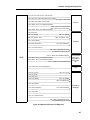
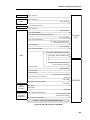
Table of Contents
Chapter 1: About This Document
Overview. . . . . . . . . . . . . . . . . . . . . . . . . . . . . . . . . . . . . . . . . . . . . . . . . . . . . . . . . . . . . . . . . . . . . 3
About Mitel MiVoice Business . . . . . . . . . . . . . . . . . . . . . . . . . . . . . . . . . . . . . . . . . . . . . . . . 3
What’s New in this Release? . . . . . . . . . . . . . . . . . . . . . . . . . . . . . . . . . . . . . . . . . . . . . . . . . 3
Changes to the Mitel MiVoice Business Engineering Guidelines . . . . . . . . . . . . . . . . . . . . . . 3
About the MiVoice Business Documentation Set . . . . . . . . . . . . . . . . . . . . . . . . . . . . . . . . . . . . . . 4
System Management Tools . . . . . . . . . . . . . . . . . . . . . . . . . . . . . . . . . . . . . . . . . . . . . . . . . . . . . . 6
About the MiVoice Business System
Engineering Tool. . . . . . . . . . . . . . . . . . . . . . . . . . . . . . . . . . . . . . . . . . . . . . . . . . . . . . . . . . . . . . . 6
Chapter 2: System Overview
System Architecture . . . . . . . . . . . . . . . . . . . . . . . . . . . . . . . . . . . . . . . . . . . . . . . . . . . . . . . . . . . . 9
MiVoice Business Controller. . . . . . . . . . . . . . . . . . . . . . . . . . . . . . . . . . . . . . . . . . . . . . . . . . . . . 10
Processor Speeds . . . . . . . . . . . . . . . . . . . . . . . . . . . . . . . . . . . . . . . . . . . . . . . . . . . . . . . . . . . 10
Supported Countries. . . . . . . . . . . . . . . . . . . . . . . . . . . . . . . . . . . . . . . . . . . . . . . . . . . . . . . . . . . 11
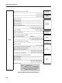
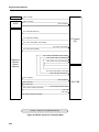
Chapter 3: Typical Configurations
System Configurations . . . . . . . . . . . . . . . . . . . . . . . . . . . . . . . . . . . . . . . . . . . . . . . . . . . . . . . . . 15
Typical Installation Configurations . . . . . . . . . . . . . . . . . . . . . . . . . . . . . . . . . . . . . . . . . . . . . . . . 16
Multiple Units System . . . . . . . . . . . . . . . . . . . . . . . . . . . . . . . . . . . . . . . . . . . . . . . . . . . . . . . . 16
Distributed System . . . . . . . . . . . . . . . . . . . . . . . . . . . . . . . . . . . . . . . . . . . . . . . . . . . . . . . . . . . 16
Hybrid System . . . . . . . . . . . . . . . . . . . . . . . . . . . . . . . . . . . . . . . . . . . . . . . . . . . . . . . . . . . . . . 18
Sample 3300 ICP Configurations . . . . . . . . . . . . . . . . . . . . . . . . . . . . . . . . . . . . . . . . . . . . . . . . . 19
The 3300 ICP as a Trunk Gateway . . . . . . . . . . . . . . . . . . . . . . . . . . . . . . . . . . . . . . . . . . . . . . 19
The 3300 ICP as a Trunk Tandem . . . . . . . . . . . . . . . . . . . . . . . . . . . . . . . . . . . . . . . . . . . . . . 20
MiVoice Business, 3300 ICP and ACD . . . . . . . . . . . . . . . . . . . . . . . . . . . . . . . . . . . . . . . . . . . 20
Standalone ACD Controller . . . . . . . . . . . . . . . . . . . . . . . . . . . . . . . . . . . . . . . . . . . . . . . . . 22
Network ACD Controllers . . . . . . . . . . . . . . . . . . . . . . . . . . . . . . . . . . . . . . . . . . . . . . . . . . . 23
ACD limits . . . . . . . . . . . . . . . . . . . . . . . . . . . . . . . . . . . . . . . . . . . . . . . . . . . . . . . . . . . . . . . 23
The 3300 ICP as a Dedicated Voice Mail Server . . . . . . . . . . . . . . . . . . . . . . . . . . . . . . . . . . . 29
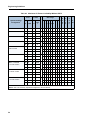
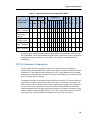
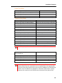
Configuration Tables. . . . . . . . . . . . . . . . . . . . . . . . . . . . . . . . . . . . . . . . . . . . . . . . . . . . . . . . . . . 30
MXe Server, Virtual MiVoice Business, MiVoice Business for ISS, and MiVoice Business Multi-instance . . . . . . . . . . . . . . . . . . . . . . . . . . . . . . . . . . . . . . . . . . . . . . . . . . . . . . . . . . . . . . . . . . . . 31
iii
Engineering Guidelines
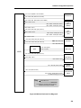
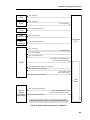
AX Controller . . . . . . . . . . . . . . . . . . . . . . . . . . . . . . . . . . . . . . . . . . . . . . . . . . . . . . . . . . . . . . . 33
AX Controller ONS port limitation . . . . . . . . . . . . . . . . . . . . . . . . . . . . . . . . . . . . . . . . . . . . . 34
CX/CXi Controller . . . . . . . . . . . . . . . . . . . . . . . . . . . . . . . . . . . . . . . . . . . . . . . . . . . . . . . . . . . . 35
CX II/CXi II Controller . . . . . . . . . . . . . . . . . . . . . . . . . . . . . . . . . . . . . . . . . . . . . . . . . . . . . . . . . 37
MXe Controller . . . . . . . . . . . . . . . . . . . . . . . . . . . . . . . . . . . . . . . . . . . . . . . . . . . . . . . . . . . . . . 38
MXe Controller 192 Gateway limitations . . . . . . . . . . . . . . . . . . . . . . . . . . . . . . . . . . . . . . . . 40
LX Controller . . . . . . . . . . . . . . . . . . . . . . . . . . . . . . . . . . . . . . . . . . . . . . . . . . . . . . . . . . . . . . . 41
Other Maximum Limits . . . . . . . . . . . . . . . . . . . . . . . . . . . . . . . . . . . . . . . . . . . . . . . . . . . . . . . . 43
SIP Phones and use of TLS (SIP-TLS) . . . . . . . . . . . . . . . . . . . . . . . . . . . . . . . . . . . . . . . . . . . 44
Use of SRTP . . . . . . . . . . . . . . . . . . . . . . . . . . . . . . . . . . . . . . . . . . . . . . . . . . . . . . . . . . . . . . . 45
Paging and Background Music Limitations . . . . . . . . . . . . . . . . . . . . . . . . . . . . . . . . . . . . . . . . 45
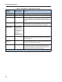
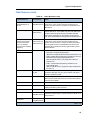
Summary of Device and User Limits . . . . . . . . . . . . . . . . . . . . . . . . . . . . . . . . . . . . . . . . . . . . . 46
HTML Applications on Sets . . . . . . . . . . . . . . . . . . . . . . . . . . . . . . . . . . . . . . . . . . . . . . . . . . . . 48
Upgrading the System . . . . . . . . . . . . . . . . . . . . . . . . . . . . . . . . . . . . . . . . . . . . . . . . . . . . . . . . . 49
Provisioning System Resources . . . . . . . . . . . . . . . . . . . . . . . . . . . . . . . . . . . . . . . . . . . . . . . . . . 50
CX Hardware Configurations . . . . . . . . . . . . . . . . . . . . . . . . . . . . . . . . . . . . . . . . . . . . . . . . . . . 51
CX/CXi II Hardware Configurations . . . . . . . . . . . . . . . . . . . . . . . . . . . . . . . . . . . . . . . . . . . . . . 53
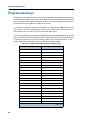
Programmable Keys . . . . . . . . . . . . . . . . . . . . . . . . . . . . . . . . . . . . . . . . . . . . . . . . . . . . . . . . . . . 54
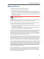
Provisioning for Traffic . . . . . . . . . . . . . . . . . . . . . . . . . . . . . . . . . . . . . . . . . . . . . . . . . . . . . . . . . 56
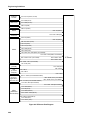
Chapter 4: Phones and Voice Applications
MiVoice IP Phones . . . . . . . . . . . . . . . . . . . . . . . . . . . . . . . . . . . . . . . . . . . . . . . . . . . . . . . . . . . . 61
5560 IPT Limits . . . . . . . . . . . . . . . . . . . . . . . . . . . . . . . . . . . . . . . . . . . . . . . . . . . . . . . . . . . . . 62
Phones Supported on the AX . . . . . . . . . . . . . . . . . . . . . . . . . . . . . . . . . . . . . . . . . . . . . . . . . . 63
Micro Firewall . . . . . . . . . . . . . . . . . . . . . . . . . . . . . . . . . . . . . . . . . . . . . . . . . . . . . . . . . . . . . . . 63
WideBand Audio . . . . . . . . . . . . . . . . . . . . . . . . . . . . . . . . . . . . . . . . . . . . . . . . . . . . . . . . . . . . 64
NuPoint Unified Messaging. . . . . . . . . . . . . . . . . . . . . . . . . . . . . . . . . . . . . . . . . . . . . . . . . . . . . . 64
DECT (Digital Enhanced Cordless Telephony). . . . . . . . . . . . . . . . . . . . . . . . . . . . . . . . . . . . . . . 64
SpectraLink Phones . . . . . . . . . . . . . . . . . . . . . . . . . . . . . . . . . . . . . . . . . . . . . . . . . . . . . . . . . . . 65
Phone Stands . . . . . . . . . . . . . . . . . . . . . . . . . . . . . . . . . . . . . . . . . . . . . . . . . . . . . . . . . . . . . . . . 65
Gigabit Ethernet Phone Stand . . . . . . . . . . . . . . . . . . . . . . . . . . . . . . . . . . . . . . . . . . . . . . . . . . 67
Power Restrictions . . . . . . . . . . . . . . . . . . . . . . . . . . . . . . . . . . . . . . . . . . . . . . . . . . . . . . . . 67
IEEE 802.11 b/g Wireless LAN Phone Stand . . . . . . . . . . . . . . . . . . . . . . . . . . . . . . . . . . . . . . 67
iv
Table of Contents
Cordless (DECT) Handset and Headset. . . . . . . . . . . . . . . . . . . . . . . . . . . . . . . . . . . . . . . . . . . . 68
System Requirements . . . . . . . . . . . . . . . . . . . . . . . . . . . . . . . . . . . . . . . . . . . . . . . . . . . . . . . . 68
Installation Recommendations . . . . . . . . . . . . . . . . . . . . . . . . . . . . . . . . . . . . . . . . . . . . . . . . . . 68
Coverage and Capacity . . . . . . . . . . . . . . . . . . . . . . . . . . . . . . . . . . . . . . . . . . . . . . . . . . . . . . . 68
Typical operating range . . . . . . . . . . . . . . . . . . . . . . . . . . . . . . . . . . . . . . . . . . . . . . . . . . . . 70
Range example . . . . . . . . . . . . . . . . . . . . . . . . . . . . . . . . . . . . . . . . . . . . . . . . . . . . . . . . . . 70
RF Site Survey . . . . . . . . . . . . . . . . . . . . . . . . . . . . . . . . . . . . . . . . . . . . . . . . . . . . . . . . . . . . . . 71
Other Considerations . . . . . . . . . . . . . . . . . . . . . . . . . . . . . . . . . . . . . . . . . . . . . . . . . . . . . . . . . 71
MiCollab Client and MiCollab Client Softphone . . . . . . . . . . . . . . . . . . . . . . . . . . . . . . . . . . . . . . 72
Access Connections . . . . . . . . . . . . . . . . . . . . . . . . . . . . . . . . . . . . . . . . . . . . . . . . . . . . . . . . . 72
Networking Considerations for MiCollab Client . . . . . . . . . . . . . . . . . . . . . . . . . . . . . . . . . . . . . 73
MiVoice Business Console . . . . . . . . . . . . . . . . . . . . . . . . . . . . . . . . . . . . . . . . . . . . . . . . . . . . . . 73
Access Connections . . . . . . . . . . . . . . . . . . . . . . . . . . . . . . . . . . . . . . . . . . . . . . . . . . . . . . . . . 73
Networking Considerations for MiVoice Business Console . . . . . . . . . . . . . . . . . . . . . . . . . . . . 74
IP Sockets and Monitors. . . . . . . . . . . . . . . . . . . . . . . . . . . . . . . . . . . . . . . . . . . . . . . . . . . . . . . . 74
System Resource Notes . . . . . . . . . . . . . . . . . . . . . . . . . . . . . . . . . . . . . . . . . . . . . . . . . . . . 81
Worked Example . . . . . . . . . . . . . . . . . . . . . . . . . . . . . . . . . . . . . . . . . . . . . . . . . . . . . . . . . . . . 81
Chapter 5: Power
Introduction . . . . . . . . . . . . . . . . . . . . . . . . . . . . . . . . . . . . . . . . . . . . . . . . . . . . . . . . . . . . . . . . . . 87
Installation Practices. . . . . . . . . . . . . . . . . . . . . . . . . . . . . . . . . . . . . . . . . . . . . . . . . . . . . . . . . . . 87
Installation Power . . . . . . . . . . . . . . . . . . . . . . . . . . . . . . . . . . . . . . . . . . . . . . . . . . . . . . . . . . . 87
Controller Power Input . . . . . . . . . . . . . . . . . . . . . . . . . . . . . . . . . . . . . . . . . . . . . . . . . . . . . . . . . 87
MiVoice IP Phone Power . . . . . . . . . . . . . . . . . . . . . . . . . . . . . . . . . . . . . . . . . . . . . . . . . . . . . . . 88
Local Phone Powering . . . . . . . . . . . . . . . . . . . . . . . . . . . . . . . . . . . . . . . . . . . . . . . . . . . . . . . . 88
Remote Phone Powering . . . . . . . . . . . . . . . . . . . . . . . . . . . . . . . . . . . . . . . . . . . . . . . . . . . . . . 88
Recommended Phone Powering . . . . . . . . . . . . . . . . . . . . . . . . . . . . . . . . . . . . . . . . . . . . . . . . 89
v
Engineering Guidelines
Options for IP Phone Powering . . . . . . . . . . . . . . . . . . . . . . . . . . . . . . . . . . . . . . . . . . . . . . . . . 90
AC Power adapters . . . . . . . . . . . . . . . . . . . . . . . . . . . . . . . . . . . . . . . . . . . . . . . . . . . . . . . . 92
In-Line Ethernet AC power adapters . . . . . . . . . . . . . . . . . . . . . . . . . . . . . . . . . . . . . . . . . . 92
In-Line Gigabit Ethernet AC power adapters . . . . . . . . . . . . . . . . . . . . . . . . . . . . . . . . . . . . 92
802.3af powering . . . . . . . . . . . . . . . . . . . . . . . . . . . . . . . . . . . . . . . . . . . . . . . . . . . . . . . . . 92
3300 CXi/CXi II ICP 802.3af Power over Ethernet capabilities . . . . . . . . . . . . . . . . . . . . . . . 93
Third party 802.3af powering . . . . . . . . . . . . . . . . . . . . . . . . . . . . . . . . . . . . . . . . . . . . . . . . 94
Mitel 3300 power dongle (Cisco compliant) . . . . . . . . . . . . . . . . . . . . . . . . . . . . . . . . . . . . . 95
Powering the 5560 IPT . . . . . . . . . . . . . . . . . . . . . . . . . . . . . . . . . . . . . . . . . . . . . . . . . . . . . 95
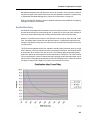
Planning a Power Over Ethernet Installation . . . . . . . . . . . . . . . . . . . . . . . . . . . . . . . . . . . . . . . . 95
Cable Power Loss . . . . . . . . . . . . . . . . . . . . . . . . . . . . . . . . . . . . . . . . . . . . . . . . . . . . . . . . . . . 96
Power Management Features in IEEE 802.3af Compliant Switches . . . . . . . . . . . . . . . . . . . . . 96
Phone Power Consumption . . . . . . . . . . . . . . . . . . . . . . . . . . . . . . . . . . . . . . . . . . . . . . . . . . . . 96
Local power . . . . . . . . . . . . . . . . . . . . . . . . . . . . . . . . . . . . . . . . . . . . . . . . . . . . . . . . . . . . . 96
Remote power . . . . . . . . . . . . . . . . . . . . . . . . . . . . . . . . . . . . . . . . . . . . . . . . . . . . . . . . . . . 99
Power Requirements for 5220 IP Phone Optional Accessories . . . . . . . . . . . . . . . . . . . . . . . . 108
System Power Requirements . . . . . . . . . . . . . . . . . . . . . . . . . . . . . . . . . . . . . . . . . . . . . . . . . 108
Uninterruptible Power Supply (UPS). . . . . . . . . . . . . . . . . . . . . . . . . . . . . . . . . . . . . . . . . . . . . . 109
Chapter 6: Performance
System Performance Index. . . . . . . . . . . . . . . . . . . . . . . . . . . . . . . . . . . . . . . . . . . . . . . . . . . . . 113
Performance Limitations . . . . . . . . . . . . . . . . . . . . . . . . . . . . . . . . . . . . . . . . . . . . . . . . . . . . . 113
Performance in an ACD Environment . . . . . . . . . . . . . . . . . . . . . . . . . . . . . . . . . . . . . . . . . . . 115
Performance with Ring Groups . . . . . . . . . . . . . . . . . . . . . . . . . . . . . . . . . . . . . . . . . . . . . . . . 116
Performance with Hunt Groups . . . . . . . . . . . . . . . . . . . . . . . . . . . . . . . . . . . . . . . . . . . . . . . . 116
Chapter 7: Applications
3300 ICP Applications . . . . . . . . . . . . . . . . . . . . . . . . . . . . . . . . . . . . . . . . . . . . . . . . . . . . . . . . 121
External Hot Desk Users . . . . . . . . . . . . . . . . . . . . . . . . . . . . . . . . . . . . . . . . . . . . . . . . . . . . . 121
Voice Mail . . . . . . . . . . . . . . . . . . . . . . . . . . . . . . . . . . . . . . . . . . . . . . . . . . . . . . . . . . . . . . . . 122
Networked Voice Mail . . . . . . . . . . . . . . . . . . . . . . . . . . . . . . . . . . . . . . . . . . . . . . . . . . . . . . . 122
Embedded Music On Hold . . . . . . . . . . . . . . . . . . . . . . . . . . . . . . . . . . . . . . . . . . . . . . . . . . . . 123
Application Processor Card . . . . . . . . . . . . . . . . . . . . . . . . . . . . . . . . . . . . . . . . . . . . . . . . . . . . 124
vi
Table of Contents
Chapter 8: Emergency Services
Emergency Services. . . . . . . . . . . . . . . . . . . . . . . . . . . . . . . . . . . . . . . . . . . . . . . . . . . . . . . . . . 129
Location Information . . . . . . . . . . . . . . . . . . . . . . . . . . . . . . . . . . . . . . . . . . . . . . . . . . . . . . . . 129
Network Configuration . . . . . . . . . . . . . . . . . . . . . . . . . . . . . . . . . . . . . . . . . . . . . . . . . . . . 129
Teleworker devices . . . . . . . . . . . . . . . . . . . . . . . . . . . . . . . . . . . . . . . . . . . . . . . . . . . . . . . 131
CESID auto updates, unsupported cConfigurations . . . . . . . . . . . . . . . . . . . . . . . . . . . . . . 132
Other considerations . . . . . . . . . . . . . . . . . . . . . . . . . . . . . . . . . . . . . . . . . . . . . . . . . . . . . 133
Chapter 9: IP Networking
IP Networking Considerations . . . . . . . . . . . . . . . . . . . . . . . . . . . . . . . . . . . . . . . . . . . . . . . . . . 137
IP Networking Node Restrictions . . . . . . . . . . . . . . . . . . . . . . . . . . . . . . . . . . . . . . . . . . . . . . . 137
Multi-Node Management Restrictions . . . . . . . . . . . . . . . . . . . . . . . . . . . . . . . . . . . . . . . . . . . 137
Clustering . . . . . . . . . . . . . . . . . . . . . . . . . . . . . . . . . . . . . . . . . . . . . . . . . . . . . . . . . . . . . . . . . 138
IP-Trunk Connection Limitations . . . . . . . . . . . . . . . . . . . . . . . . . . . . . . . . . . . . . . . . . . . . . . . 139
IP trunking models . . . . . . . . . . . . . . . . . . . . . . . . . . . . . . . . . . . . . . . . . . . . . . . . . . . . . . . 140
Call Handling, Routing, and Bandwidth . . . . . . . . . . . . . . . . . . . . . . . . . . . . . . . . . . . . . . . . . . 141
Variable RTP Packet Rates . . . . . . . . . . . . . . . . . . . . . . . . . . . . . . . . . . . . . . . . . . . . . . . . . . . 143
Constraints . . . . . . . . . . . . . . . . . . . . . . . . . . . . . . . . . . . . . . . . . . . . . . . . . . . . . . . . . . . . . 143
Service provider behavior . . . . . . . . . . . . . . . . . . . . . . . . . . . . . . . . . . . . . . . . . . . . . . . . . . 144
Route Optimization . . . . . . . . . . . . . . . . . . . . . . . . . . . . . . . . . . . . . . . . . . . . . . . . . . . . . . . . . 144
Automatic Route Selection . . . . . . . . . . . . . . . . . . . . . . . . . . . . . . . . . . . . . . . . . . . . . . . . . . . 145
Number Planning and Restrictions . . . . . . . . . . . . . . . . . . . . . . . . . . . . . . . . . . . . . . . . . . . . . 145
IP Networking and Product Release Compatibility . . . . . . . . . . . . . . . . . . . . . . . . . . . . . . . . . 146
SIP Trunking . . . . . . . . . . . . . . . . . . . . . . . . . . . . . . . . . . . . . . . . . . . . . . . . . . . . . . . . . . . . . . . . 146
SIP Trunking Basics . . . . . . . . . . . . . . . . . . . . . . . . . . . . . . . . . . . . . . . . . . . . . . . . . . . . . . . . 146
Licenses . . . . . . . . . . . . . . . . . . . . . . . . . . . . . . . . . . . . . . . . . . . . . . . . . . . . . . . . . . . . . . . 146
Networking ICPs with IP trunks . . . . . . . . . . . . . . . . . . . . . . . . . . . . . . . . . . . . . . . . . . . . . 146
Networking ICPs with TDM trunks . . . . . . . . . . . . . . . . . . . . . . . . . . . . . . . . . . . . . . . . . . . 146
Applications compatibility . . . . . . . . . . . . . . . . . . . . . . . . . . . . . . . . . . . . . . . . . . . . . . . . . . 147
Third-party phone compatibility . . . . . . . . . . . . . . . . . . . . . . . . . . . . . . . . . . . . . . . . . . . . . 147
Support for FAX over IP . . . . . . . . . . . . . . . . . . . . . . . . . . . . . . . . . . . . . . . . . . . . . . . . . . . 147
SIP aware firewall . . . . . . . . . . . . . . . . . . . . . . . . . . . . . . . . . . . . . . . . . . . . . . . . . . . . . . . . 148
TCP/IP port usage . . . . . . . . . . . . . . . . . . . . . . . . . . . . . . . . . . . . . . . . . . . . . . . . . . . . . . . 149
Resiliency . . . . . . . . . . . . . . . . . . . . . . . . . . . . . . . . . . . . . . . . . . . . . . . . . . . . . . . . . . . . . . 150
911 emergency services . . . . . . . . . . . . . . . . . . . . . . . . . . . . . . . . . . . . . . . . . . . . . . . . . . . 150
vii
Engineering Guidelines
Chapter 10: Licensing
System Licenses. . . . . . . . . . . . . . . . . . . . . . . . . . . . . . . . . . . . . . . . . . . . . . . . . . . . . . . . . . . . . 153
Device Licensing. . . . . . . . . . . . . . . . . . . . . . . . . . . . . . . . . . . . . . . . . . . . . . . . . . . . . . . . . . . . . 158
Licensing Limits . . . . . . . . . . . . . . . . . . . . . . . . . . . . . . . . . . . . . . . . . . . . . . . . . . . . . . . . . . . . . 161
Licensing Example . . . . . . . . . . . . . . . . . . . . . . . . . . . . . . . . . . . . . . . . . . . . . . . . . . . . . . . . . . 162
Application Management Center (AMC) . . . . . . . . . . . . . . . . . . . . . . . . . . . . . . . . . . . . . . . . . . . 164
Chapter 11: Bandwidth, Codecs and Compression
Bandwidth, Bandwidth Management, Codecs and Compression . . . . . . . . . . . . . . . . . . . . . . . . 167
Calculating and Measuring Bandwidth . . . . . . . . . . . . . . . . . . . . . . . . . . . . . . . . . . . . . . . . . . . 167
Bandwidth availability . . . . . . . . . . . . . . . . . . . . . . . . . . . . . . . . . . . . . . . . . . . . . . . . . . . . . 171
Bandwidth Management . . . . . . . . . . . . . . . . . . . . . . . . . . . . . . . . . . . . . . . . . . . . . . . . . . . . .173
Bandwidth management and call admission control . . . . . . . . . . . . . . . . . . . . . . . . . . . . . . 173
Codec – Introduction . . . . . . . . . . . . . . . . . . . . . . . . . . . . . . . . . . . . . . . . . . . . . . . . . . . . . . . . 180
Voice quality and codec selection . . . . . . . . . . . . . . . . . . . . . . . . . . . . . . . . . . . . . . . . . . . . 181
Codec selection . . . . . . . . . . . . . . . . . . . . . . . . . . . . . . . . . . . . . . . . . . . . . . . . . . . . . . . . . 181
Operation through MiVoice Border Gateway and SRC . . . . . . . . . . . . . . . . . . . . . . . . . . . . . . 185
Compression – Introduction . . . . . . . . . . . . . . . . . . . . . . . . . . . . . . . . . . . . . . . . . . . . . . . . . . . 185
3300 ICP compression guidelines . . . . . . . . . . . . . . . . . . . . . . . . . . . . . . . . . . . . . . . . . . . 186
Trunking gateway working example . . . . . . . . . . . . . . . . . . . . . . . . . . . . . . . . . . . . . . . . . . 188
IP networking routes and compression . . . . . . . . . . . . . . . . . . . . . . . . . . . . . . . . . . . . . . . . 188
IP trunk routes and compression . . . . . . . . . . . . . . . . . . . . . . . . . . . . . . . . . . . . . . . . . . . . 190
IP networking and compression licenses . . . . . . . . . . . . . . . . . . . . . . . . . . . . . . . . . . . . . . 190
Compression and licenses . . . . . . . . . . . . . . . . . . . . . . . . . . . . . . . . . . . . . . . . . . . . . . . . . 190
Chapter 12: Network Configuration Concepts
Introduction . . . . . . . . . . . . . . . . . . . . . . . . . . . . . . . . . . . . . . . . . . . . . . . . . . . . . . . . . . . . . . . . . 193
Network Configuration Guidelines . . . . . . . . . . . . . . . . . . . . . . . . . . . . . . . . . . . . . . . . . . . . . . . 194
Voice-Over-IP Installation Requirements . . . . . . . . . . . . . . . . . . . . . . . . . . . . . . . . . . . . . . . . . . 197
General Guidelines for Quality of Service. . . . . . . . . . . . . . . . . . . . . . . . . . . . . . . . . . . . . . . . . . 199
viii
Table of Contents
Basic Concepts . . . . . . . . . . . . . . . . . . . . . . . . . . . . . . . . . . . . . . . . . . . . . . . . . . . . . . . . . . . . 199
Delay . . . . . . . . . . . . . . . . . . . . . . . . . . . . . . . . . . . . . . . . . . . . . . . . . . . . . . . . . . . . . . . . . 199
Echo . . . . . . . . . . . . . . . . . . . . . . . . . . . . . . . . . . . . . . . . . . . . . . . . . . . . . . . . . . . . . . . . . . 199
Jitter . . . . . . . . . . . . . . . . . . . . . . . . . . . . . . . . . . . . . . . . . . . . . . . . . . . . . . . . . . . . . . . . . . 199
Packet loss . . . . . . . . . . . . . . . . . . . . . . . . . . . . . . . . . . . . . . . . . . . . . . . . . . . . . . . . . . . . . 200
Available bandwidth . . . . . . . . . . . . . . . . . . . . . . . . . . . . . . . . . . . . . . . . . . . . . . . . . . . . . . 200
Packet priority mechanisms . . . . . . . . . . . . . . . . . . . . . . . . . . . . . . . . . . . . . . . . . . . . . . . . 200
WAN connections . . . . . . . . . . . . . . . . . . . . . . . . . . . . . . . . . . . . . . . . . . . . . . . . . . . . . . . . 200
Transcoding and compression . . . . . . . . . . . . . . . . . . . . . . . . . . . . . . . . . . . . . . . . . . . . . . 201
Wideband voice . . . . . . . . . . . . . . . . . . . . . . . . . . . . . . . . . . . . . . . . . . . . . . . . . . . . . . . . . 201
Hub network versus switched network . . . . . . . . . . . . . . . . . . . . . . . . . . . . . . . . . . . . . . . . 202
LAN architecture . . . . . . . . . . . . . . . . . . . . . . . . . . . . . . . . . . . . . . . . . . . . . . . . . . . . . . . . . 202
Operating with SX-2000 and Third-Party PBXs . . . . . . . . . . . . . . . . . . . . . . . . . . . . . . . . . . . . . 204
Maintaining Voice Quality of Service . . . . . . . . . . . . . . . . . . . . . . . . . . . . . . . . . . . . . . . . . . . . . 205
VoIP Readiness Assessment . . . . . . . . . . . . . . . . . . . . . . . . . . . . . . . . . . . . . . . . . . . . . . . . . 205
Network Measurement Criteria . . . . . . . . . . . . . . . . . . . . . . . . . . . . . . . . . . . . . . . . . . . . . . . . 206
Bandwidth Requirements . . . . . . . . . . . . . . . . . . . . . . . . . . . . . . . . . . . . . . . . . . . . . . . . . . . . . 206
Serialization Delay . . . . . . . . . . . . . . . . . . . . . . . . . . . . . . . . . . . . . . . . . . . . . . . . . . . . . . . . . . 207
Network Priority Mechanisms . . . . . . . . . . . . . . . . . . . . . . . . . . . . . . . . . . . . . . . . . . . . . . . . . 209
LAN layer 2 priority . . . . . . . . . . . . . . . . . . . . . . . . . . . . . . . . . . . . . . . . . . . . . . . . . . . . . . . 209
WAN layer 3 priority . . . . . . . . . . . . . . . . . . . . . . . . . . . . . . . . . . . . . . . . . . . . . . . . . . . . . . 213
Network topology with priority . . . . . . . . . . . . . . . . . . . . . . . . . . . . . . . . . . . . . . . . . . . . . . . 216
LAN QoS policies . . . . . . . . . . . . . . . . . . . . . . . . . . . . . . . . . . . . . . . . . . . . . . . . . . . . . . . . 217
TOS-to-COS (IEEE 802.1p) mapping and softphones . . . . . . . . . . . . . . . . . . . . . . . . . . . . 217
Use of subnets and subnet size . . . . . . . . . . . . . . . . . . . . . . . . . . . . . . . . . . . . . . . . . . . . . 218
Full Duplex and Half Duplex Settings . . . . . . . . . . . . . . . . . . . . . . . . . . . . . . . . . . . . . . . . . . . 218
Full duplex network basics . . . . . . . . . . . . . . . . . . . . . . . . . . . . . . . . . . . . . . . . . . . . . . . . . 218
Half duplex network basics . . . . . . . . . . . . . . . . . . . . . . . . . . . . . . . . . . . . . . . . . . . . . . . . . 219
Summary . . . . . . . . . . . . . . . . . . . . . . . . . . . . . . . . . . . . . . . . . . . . . . . . . . . . . . . . . . . . . . 219
Maintaining Availability of Connections . . . . . . . . . . . . . . . . . . . . . . . . . . . . . . . . . . . . . . . . . . . 220
System Capabilities . . . . . . . . . . . . . . . . . . . . . . . . . . . . . . . . . . . . . . . . . . . . . . . . . . . . . . . . . 220
Traffic and Bandwidth Calculations . . . . . . . . . . . . . . . . . . . . . . . . . . . . . . . . . . . . . . . . . . . . . 220
WAN traffic working example . . . . . . . . . . . . . . . . . . . . . . . . . . . . . . . . . . . . . . . . . . . . . . . 221
IP networking and Use of Compression . . . . . . . . . . . . . . . . . . . . . . . . . . . . . . . . . . . . . . . . . 222
IP networking limit working example . . . . . . . . . . . . . . . . . . . . . . . . . . . . . . . . . . . . . . . . . . 223
Firewalls and NAT . . . . . . . . . . . . . . . . . . . . . . . . . . . . . . . . . . . . . . . . . . . . . . . . . . . . . . . . . . 225
ix
Engineering Guidelines
Chapter 13: Network Configuration Specifics
Network Configuration Specifics . . . . . . . . . . . . . . . . . . . . . . . . . . . . . . . . . . . . . . . . . . . . . . . . . 229
Start-Up Sequence and DHCP . . . . . . . . . . . . . . . . . . . . . . . . . . . . . . . . . . . . . . . . . . . . . . . . . . 230
Startup Sequence for Phones . . . . . . . . . . . . . . . . . . . . . . . . . . . . . . . . . . . . . . . . . . . . . . . . . 230
Options for obtaining LAN Policy setting information per software release . . . . . . . . . . . . 230
Sources that can be used to obtain network policy information . . . . . . . . . . . . . . . . . . . . . 231
Network configuration information and priorities . . . . . . . . . . . . . . . . . . . . . . . . . . . . . . . . . 231
VLAN setting information sources and priorities . . . . . . . . . . . . . . . . . . . . . . . . . . . . . . . . . 232
L2 and L3 QoS information sources and priorities . . . . . . . . . . . . . . . . . . . . . . . . . . . . . . . 232
Potential issues with using LLDP-MED in Cisco environments . . . . . . . . . . . . . . . . . . . . . 233
LAN policy values for media, signalling and other . . . . . . . . . . . . . . . . . . . . . . . . . . . . . . . 234
DSCP settings for call signalling in Cisco environments . . . . . . . . . . . . . . . . . . . . . . . . . . 235
DHCP and IP Phone network policy . . . . . . . . . . . . . . . . . . . . . . . . . . . . . . . . . . . . . . . . . . 235
LLDP-MED and IP Phone network policy . . . . . . . . . . . . . . . . . . . . . . . . . . . . . . . . . . . . . . 236
IP Phones and VLAN programmability . . . . . . . . . . . . . . . . . . . . . . . . . . . . . . . . . . . . . . . . 238
RFC 3942, reclassifying DHCP options: DeTeWe and Spectralink Phones . . . . . . . . . . . . 239
5302 Startup and DHCP . . . . . . . . . . . . . . . . . . . . . . . . . . . . . . . . . . . . . . . . . . . . . . . . . . . . . 240
Startup Sequence for the Controller . . . . . . . . . . . . . . . . . . . . . . . . . . . . . . . . . . . . . . . . . . . . 240
Mitel Communication Director . . . . . . . . . . . . . . . . . . . . . . . . . . . . . . . . . . . . . . . . . . . . . . . 240
DHCP Option Reclassification . . . . . . . . . . . . . . . . . . . . . . . . . . . . . . . . . . . . . . . . . . . . . . . . . 241
IP Phone behavior . . . . . . . . . . . . . . . . . . . . . . . . . . . . . . . . . . . . . . . . . . . . . . . . . . . . . . . 242
Vendor information data format (options 125 and 43) . . . . . . . . . . . . . . . . . . . . . . . . . . . . 243
Support of solution by external DHCP servers . . . . . . . . . . . . . . . . . . . . . . . . . . . . . . . . . . 244
DHCP Lease Time . . . . . . . . . . . . . . . . . . . . . . . . . . . . . . . . . . . . . . . . . . . . . . . . . . . . . . . . . . 245
3300 TFTP Server . . . . . . . . . . . . . . . . . . . . . . . . . . . . . . . . . . . . . . . . . . . . . . . . . . . . . . . . . . 245
VMPS, CDP, and Location Change Indication (E911) . . . . . . . . . . . . . . . . . . . . . . . . . . . . . . . . 247
Summary . . . . . . . . . . . . . . . . . . . . . . . . . . . . . . . . . . . . . . . . . . . . . . . . . . . . . . . . . . . . . . . . . 247
CDP and VMPS . . . . . . . . . . . . . . . . . . . . . . . . . . . . . . . . . . . . . . . . . . . . . . . . . . . . . . . . .247
STP . . . . . . . . . . . . . . . . . . . . . . . . . . . . . . . . . . . . . . . . . . . . . . . . . . . . . . . . . . . . . . . . . . . 248
Network QoS settings in a Cisco Environment . . . . . . . . . . . . . . . . . . . . . . . . . . . . . . . . . . . . 248
Port Settings . . . . . . . . . . . . . . . . . . . . . . . . . . . . . . . . . . . . . . . . . . . . . . . . . . . . . . . . . . . . . . 249
3300 ICP multiple network connections . . . . . . . . . . . . . . . . . . . . . . . . . . . . . . . . . . . . . . . 249
Applications and other voice servers . . . . . . . . . . . . . . . . . . . . . . . . . . . . . . . . . . . . . . . . . 250
MiVoice IP Phone . . . . . . . . . . . . . . . . . . . . . . . . . . . . . . . . . . . . . . . . . . . . . . . . . . . . . . . . 251
Location change indication . . . . . . . . . . . . . . . . . . . . . . . . . . . . . . . . . . . . . . . . . . . . . . . . . 251
VLAN/CDP network port configurations . . . . . . . . . . . . . . . . . . . . . . . . . . . . . . . . . . . . . . . 251
VLAN Membership Policy Server (VMPS) . . . . . . . . . . . . . . . . . . . . . . . . . . . . . . . . . . . . . . . . 253
VMPS and network switch software revisions . . . . . . . . . . . . . . . . . . . . . . . . . . . . . . . . . . 255
Use of VMPS with 3300 ICP . . . . . . . . . . . . . . . . . . . . . . . . . . . . . . . . . . . . . . . . . . . . . . . . 255
x
Table of Contents
Network Considerations . . . . . . . . . . . . . . . . . . . . . . . . . . . . . . . . . . . . . . . . . . . . . . . . . . . . . . . 257
NetBIOS and PC Settings . . . . . . . . . . . . . . . . . . . . . . . . . . . . . . . . . . . . . . . . . . . . . . . . . . . . 257
Wireless Phone Performance on the 3300 ICP . . . . . . . . . . . . . . . . . . . . . . . . . . . . . . . . . . . . 258
SpectraLink wireless phones . . . . . . . . . . . . . . . . . . . . . . . . . . . . . . . . . . . . . . . . . . . . . . . 258
Mitel WLAN phones . . . . . . . . . . . . . . . . . . . . . . . . . . . . . . . . . . . . . . . . . . . . . . . . . . . . . . 258
DECT wireless phones for deployment in Europe, Middle-East, and Africa . . . . . . . . . . . . 258
DECT wireless phones for deployment in Europe and North America . . . . . . . . . . . . . . . . 259
Wireless LAN considerations . . . . . . . . . . . . . . . . . . . . . . . . . . . . . . . . . . . . . . . . . . . . . . . 259
Coverage and capacity . . . . . . . . . . . . . . . . . . . . . . . . . . . . . . . . . . . . . . . . . . . . . . . . . . . . 260
Connectivity to the wired LAN . . . . . . . . . . . . . . . . . . . . . . . . . . . . . . . . . . . . . . . . . . . . . . 260
Other considerations . . . . . . . . . . . . . . . . . . . . . . . . . . . . . . . . . . . . . . . . . . . . . . . . . . . . . 261
Fax and modem connections over IP using G.711 Pass Through . . . . . . . . . . . . . . . . . . . . . 261
G.711 Fax pass through overview . . . . . . . . . . . . . . . . . . . . . . . . . . . . . . . . . . . . . . . . . . . 261
G.711 Fax pass through performance guidelines . . . . . . . . . . . . . . . . . . . . . . . . . . . . . . . . 262
T.38 – reliable Fax over IP transport . . . . . . . . . . . . . . . . . . . . . . . . . . . . . . . . . . . . . . . . . 262
G.711 modem pass through . . . . . . . . . . . . . . . . . . . . . . . . . . . . . . . . . . . . . . . . . . . . . . . . 262
DTMF Signalling over IP Networks . . . . . . . . . . . . . . . . . . . . . . . . . . . . . . . . . . . . . . . . . . . . . 263
T.38 FoIP Guidelines . . . . . . . . . . . . . . . . . . . . . . . . . . . . . . . . . . . . . . . . . . . . . . . . . . . . . . . . 263
DSP II . . . . . . . . . . . . . . . . . . . . . . . . . . . . . . . . . . . . . . . . . . . . . . . . . . . . . . . . . . . . . . . . . 264
Signalling . . . . . . . . . . . . . . . . . . . . . . . . . . . . . . . . . . . . . . . . . . . . . . . . . . . . . . . . . . . . . . 264
Operation . . . . . . . . . . . . . . . . . . . . . . . . . . . . . . . . . . . . . . . . . . . . . . . . . . . . . . . . . . . . . . 264
Line Circuits and COS Options . . . . . . . . . . . . . . . . . . . . . . . . . . . . . . . . . . . . . . . . . . . . . . 265
Resources required . . . . . . . . . . . . . . . . . . . . . . . . . . . . . . . . . . . . . . . . . . . . . . . . . . . . . . 266
DSP provisioning . . . . . . . . . . . . . . . . . . . . . . . . . . . . . . . . . . . . . . . . . . . . . . . . . . . . . . . . 266
Zones . . . . . . . . . . . . . . . . . . . . . . . . . . . . . . . . . . . . . . . . . . . . . . . . . . . . . . . . . . . . . . . . . 266
Inter-zone default profile . . . . . . . . . . . . . . . . . . . . . . . . . . . . . . . . . . . . . . . . . . . . . . . . . . . 267
Intra-zone default profile . . . . . . . . . . . . . . . . . . . . . . . . . . . . . . . . . . . . . . . . . . . . . . . . . . . 267
Other intra-zone profiles . . . . . . . . . . . . . . . . . . . . . . . . . . . . . . . . . . . . . . . . . . . . . . . . . . . 267
Recommended settings . . . . . . . . . . . . . . . . . . . . . . . . . . . . . . . . . . . . . . . . . . . . . . . . . . . 267
What happens if there are insufficient DSP resources or T.38 licenses? . . . . . . . . . . . . . . 268
Are there fax speed restrictions? . . . . . . . . . . . . . . . . . . . . . . . . . . . . . . . . . . . . . . . . . . . . 268
Bandwidth Management . . . . . . . . . . . . . . . . . . . . . . . . . . . . . . . . . . . . . . . . . . . . . . . . . . . . . 268
Minimum network requirements . . . . . . . . . . . . . . . . . . . . . . . . . . . . . . . . . . . . . . . . . . . . . 268
T.38 Alarms . . . . . . . . . . . . . . . . . . . . . . . . . . . . . . . . . . . . . . . . . . . . . . . . . . . . . . . . . . . . . . . 270
T.38 load alarm . . . . . . . . . . . . . . . . . . . . . . . . . . . . . . . . . . . . . . . . . . . . . . . . . . . . . . . . . . 270
DSP resource exhaustion alarm . . . . . . . . . . . . . . . . . . . . . . . . . . . . . . . . . . . . . . . . . . . . . 270
T.38 Frequently Asked Questions . . . . . . . . . . . . . . . . . . . . . . . . . . . . . . . . . . . . . . . . . . . . . . 270
3300 IP Ports . . . . . . . . . . . . . . . . . . . . . . . . . . . . . . . . . . . . . . . . . . . . . . . . . . . . . . . . . . . . . . 271
Embedded firewalls . . . . . . . . . . . . . . . . . . . . . . . . . . . . . . . . . . . . . . . . . . . . . . . . . . . . . . 285
Voice gateway IP ports . . . . . . . . . . . . . . . . . . . . . . . . . . . . . . . . . . . . . . . . . . . . . . . . . . . . 285
xi
Engineering Guidelines
IP Address Restrictions . . . . . . . . . . . . . . . . . . . . . . . . . . . . . . . . . . . . . . . . . . . . . . . . . . . . . . 285
Cables and Connections . . . . . . . . . . . . . . . . . . . . . . . . . . . . . . . . . . . . . . . . . . . . . . . . . . . . . 286
Cable types . . . . . . . . . . . . . . . . . . . . . . . . . . . . . . . . . . . . . . . . . . . . . . . . . . . . . . . . . . . . . 286
Ethernet cable distances . . . . . . . . . . . . . . . . . . . . . . . . . . . . . . . . . . . . . . . . . . . . . . . . . . 287
Straight and crossover cables . . . . . . . . . . . . . . . . . . . . . . . . . . . . . . . . . . . . . . . . . . . . . . 288
Identification of connection cables . . . . . . . . . . . . . . . . . . . . . . . . . . . . . . . . . . . . . . . . . . . 288
IP Phone LAN Speed Restrictions . . . . . . . . . . . . . . . . . . . . . . . . . . . . . . . . . . . . . . . . . . . . . . 289
Interconnection Summary . . . . . . . . . . . . . . . . . . . . . . . . . . . . . . . . . . . . . . . . . . . . . . . . . . . . 290
Appendix A: CAT 3 Wiring
CAT 3 Wiring Practices. . . . . . . . . . . . . . . . . . . . . . . . . . . . . . . . . . . . . . . . . . . . . . . . . . . . . . . . 293
Common Guidelines and Restrictions for CAT 3 Installations . . . . . . . . . . . . . . . . . . . . . . . . . 293
Summary of CAT 3-specific Network Configurations . . . . . . . . . . . . . . . . . . . . . . . . . . . . . . . . 295
Appendix B: Installation Examples
Using Cisco Routers and Catalyst Switches. . . . . . . . . . . . . . . . . . . . . . . . . . . . . . . . . . . . . . . . 301
Basic Rules . . . . . . . . . . . . . . . . . . . . . . . . . . . . . . . . . . . . . . . . . . . . . . . . . . . . . . . . . . . . . . . 301
Basic IP Addressing Information . . . . . . . . . . . . . . . . . . . . . . . . . . . . . . . . . . . . . . . . . . . . . . . 301
Basic Quality of Service (QoS) . . . . . . . . . . . . . . . . . . . . . . . . . . . . . . . . . . . . . . . . . . . . . . . . 301
Define the IP Addressing . . . . . . . . . . . . . . . . . . . . . . . . . . . . . . . . . . . . . . . . . . . . . . . . . . . . . 302
Define the VLAN . . . . . . . . . . . . . . . . . . . . . . . . . . . . . . . . . . . . . . . . . . . . . . . . . . . . . . . . . . . 302
MiVoice IP Phone . . . . . . . . . . . . . . . . . . . . . . . . . . . . . . . . . . . . . . . . . . . . . . . . . . . . . . . . . . 303
Example Network Topology . . . . . . . . . . . . . . . . . . . . . . . . . . . . . . . . . . . . . . . . . . . . . . . . . . . 303
Ethernet Switch 1 configuration . . . . . . . . . . . . . . . . . . . . . . . . . . . . . . . . . . . . . . . . . . . . . 304
Ethernet Switch 2 configuration . . . . . . . . . . . . . . . . . . . . . . . . . . . . . . . . . . . . . . . . . . . . . 306
Ethernet Switch 3 configuration . . . . . . . . . . . . . . . . . . . . . . . . . . . . . . . . . . . . . . . . . . . . . 307
Router 1 configuration . . . . . . . . . . . . . . . . . . . . . . . . . . . . . . . . . . . . . . . . . . . . . . . . . . . . 308
. . . . . . . . . . . . . . . . . . . . . . . . . . . . . . . . . . . . . . . . . . . . . . . . . . . . . . . . . . . . . . . . . . . . . . 309
Setting up QoS for Router1 using Low Latency Queuing . . . . . . . . . . . . . . . . . . . . . . . . . . 309
. . . . . . . . . . . . . . . . . . . . . . . . . . . . . . . . . . . . . . . . . . . . . . . . . . . . . . . . . . . . . . . . . . . . . . 311
Router 2 configuration . . . . . . . . . . . . . . . . . . . . . . . . . . . . . . . . . . . . . . . . . . . . . . . . . . . . 311
. . . . . . . . . . . . . . . . . . . . . . . . . . . . . . . . . . . . . . . . . . . . . . . . . . . . . . . . . . . . . . . . . . . . . . 312
Setting up QoS for Router2 using Low Latency Queuing . . . . . . . . . . . . . . . . . . . . . . . . . . 312
. . . . . . . . . . . . . . . . . . . . . . . . . . . . . . . . . . . . . . . . . . . . . . . . . . . . . . . . . . . . . . . . . . . . . . 314
Miscellaneous . . . . . . . . . . . . . . . . . . . . . . . . . . . . . . . . . . . . . . . . . . . . . . . . . . . . . . . . . . . 314
Using the CXi/CXi II or MXe Internet Gateway . . . . . . . . . . . . . . . . . . . . . . . . . . . . . . . . . . . . . . 315
xii
Table of Contents
Appendix C: LLDP and LLDP-MED Configuration Examples
LLDP, LLDP-MED Overview. . . . . . . . . . . . . . . . . . . . . . . . . . . . . . . . . . . . . . . . . . . . . . . . . . . . 319
Configuration Overview . . . . . . . . . . . . . . . . . . . . . . . . . . . . . . . . . . . . . . . . . . . . . . . . . . . . . . 319
LLDP-MED advertising information determination . . . . . . . . . . . . . . . . . . . . . . . . . . . . . . . 319
Quick Start – Getting LLDP-MED Running Quickly . . . . . . . . . . . . . . . . . . . . . . . . . . . . . . . . . 321
LLDP-MED for Network Policy Information (VLAN & QoS) . . . . . . . . . . . . . . . . . . . . . . . . . . . 321
Defining voice VLAN and ports . . . . . . . . . . . . . . . . . . . . . . . . . . . . . . . . . . . . . . . . . . . . . . 322
Defining DSCP to Priority (COS) mapping (optional) . . . . . . . . . . . . . . . . . . . . . . . . . . . . . 323
Applying DSCP to Priority QoS Policy Enforcement at the Access Port (optional) . . . . . . 324
Applying PER VLAN Priority and DSCP QOS (optional) . . . . . . . . . . . . . . . . . . . . . . . . . . 325
Connecting non-VLAN enabled voice devices to the network . . . . . . . . . . . . . . . . . . . . . . 325
Ensure that LLDP is enabled . . . . . . . . . . . . . . . . . . . . . . . . . . . . . . . . . . . . . . . . . . . . . . . 326
LLDP-MED for Location Information . . . . . . . . . . . . . . . . . . . . . . . . . . . . . . . . . . . . . . . . . . . . 326
Additional Useful Commands . . . . . . . . . . . . . . . . . . . . . . . . . . . . . . . . . . . . . . . . . . . . . . . . . 327
Appendix D: VoIP and VLANs
VoIP Installation and VLAN Configurations . . . . . . . . . . . . . . . . . . . . . . . . . . . . . . . . . . . . . . . . 333
When to use VLANs? . . . . . . . . . . . . . . . . . . . . . . . . . . . . . . . . . . . . . . . . . . . . . . . . . . . . . . . 333
Network Configurations . . . . . . . . . . . . . . . . . . . . . . . . . . . . . . . . . . . . . . . . . . . . . . . . . . . . . . 333
Standalone CXi, voice only . . . . . . . . . . . . . . . . . . . . . . . . . . . . . . . . . . . . . . . . . . . . . . . . . 334
Physical segregation of voice and data networks . . . . . . . . . . . . . . . . . . . . . . . . . . . . . . . . 334
Standalone CXi without expansion switch, dedicated voice and data ports . . . . . . . . . . . . 335
Expanded CXi, dedicated voice and data ports . . . . . . . . . . . . . . . . . . . . . . . . . . . . . . . . . 335
Common network connection for both voice and data devices . . . . . . . . . . . . . . . . . . . . . 335
Connection to corporate network . . . . . . . . . . . . . . . . . . . . . . . . . . . . . . . . . . . . . . . . . . . . 335
Appendix E: VoIP Security
Security Support with Mitel VoIP . . . . . . . . . . . . . . . . . . . . . . . . . . . . . . . . . . . . . . . . . . . . . . . . 339
Data Encryption . . . . . . . . . . . . . . . . . . . . . . . . . . . . . . . . . . . . . . . . . . . . . . . . . . . . . . . . . . . . 339
Bandwidth considerations (voice and signalling encryption) . . . . . . . . . . . . . . . . . . . . . . . 339
Signalling and media paths . . . . . . . . . . . . . . . . . . . . . . . . . . . . . . . . . . . . . . . . . . . . . . . . 340
Voice streaming security (SRTP) . . . . . . . . . . . . . . . . . . . . . . . . . . . . . . . . . . . . . . . . . . . . 341
Signalling security . . . . . . . . . . . . . . . . . . . . . . . . . . . . . . . . . . . . . . . . . . . . . . . . . . . . . . . . 341
Voice streaming to external gateway PSTN connection . . . . . . . . . . . . . . . . . . . . . . . . . . . 342
Voice streaming to TDM connections . . . . . . . . . . . . . . . . . . . . . . . . . . . . . . . . . . . . . . . . . 342
Voice streaming to internal voice mail, Record-a-Call and conference . . . . . . . . . . . . . . . 343
Voice streaming to applications . . . . . . . . . . . . . . . . . . . . . . . . . . . . . . . . . . . . . . . . . . . . . 343
Data encryption support . . . . . . . . . . . . . . . . . . . . . . . . . . . . . . . . . . . . . . . . . . . . . . . . . . . 343
Authentication Protocol Support . . . . . . . . . . . . . . . . . . . . . . . . . . . . . . . . . . . . . . . . . . . . . . . . . 346
xiii
Engineering Guidelines
Dual Port Phones . . . . . . . . . . . . . . . . . . . . . . . . . . . . . . . . . . . . . . . . . . . . . . . . . . . . . . . . . . . 346
IEEE 802.1X . . . . . . . . . . . . . . . . . . . . . . . . . . . . . . . . . . . . . . . . . . . . . . . . . . . . . . . . . . . . . . 346
Devices that support 802.1X . . . . . . . . . . . . . . . . . . . . . . . . . . . . . . . . . . . . . . . . . . . . . . . . 348
Worm and virus protection . . . . . . . . . . . . . . . . . . . . . . . . . . . . . . . . . . . . . . . . . . . . . . . . . 349
Prevention of toll abuse . . . . . . . . . . . . . . . . . . . . . . . . . . . . . . . . . . . . . . . . . . . . . . . . . . . 349
Secure management interfaces . . . . . . . . . . . . . . . . . . . . . . . . . . . . . . . . . . . . . . . . . . . . . 350
Multi-Level Precedence and Preemption (MLPP) . . . . . . . . . . . . . . . . . . . . . . . . . . . . . . . . . . 350
SIP Security . . . . . . . . . . . . . . . . . . . . . . . . . . . . . . . . . . . . . . . . . . . . . . . . . . . . . . . . . . . . . . . 350
Glossary . . . . . . . . . . . . . . . . . . . . . . . . . . . . . . . . . . . . . . . . . . . . . . . . . . . . . . . . . . . . . . . . . . . 351
Index . . . . . . . . . . . . . . . . . . . . . . . . . . . . . . . . . . . . . . . . . . . . . . . . . . . . . . . . . . . . . . . . . . . . . . 361
xiv
CHAPTER 1
ABOUT THIS DOCUMENT
About This Document
Overview
These guidelines will assist you in planning an installation of a 3300 IP Communications
Platform. The guidelines describe specific areas of the product that need to be considered
before installation. Also, field experience highlights specific areas that might not have previously
been covered. These guidelines should not be considered as a comprehensive list, but as
useful reminders or pointers that should be considered before installation.
The contents of this document gather general platform guidelines together. Where there are
guidelines that are specific to a feature or a particular use of a product, then this document may
contain references to those specific documents. Typical examples of this include references to
"Resiliency" or use of IP networking and Clustering configurations where specific documents
can provide more extensive detail.
In planning an installation other documents should also be referenced in addition to these
Engineering Guidelines. Most of these can be found on Mitel-On-Line and are highlighted in
the following section "About the 3300 ICP Documentation Set".
About Mitel MiVoice Business
Mitel® MiVoice Business is the brand name of the call-processing software that runs on
hardware platforms such as the 3300 ICP. The 3300 ICP name is the brand name for Mitel
hardware platforms that run MiVoice Business.
3300 ICP Release 9.0 was the last software release under the original branding scheme. It was
replaced by the Mitel Communications Director (MCD) brand and released as "Release 4.0."
Release 7.0 marks the latest rebranding to Mitel MiVoice Business.
What’s New in this Release?
New features and capabilities introduced in each release are disucssed in this document but
only if they have engineering implications. For a complete list of what’s new in a release, see
the System Administration Tool Help for MiVoice Business.
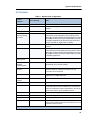
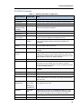
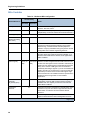
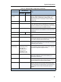
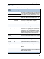
Changes to the Mitel MiVoice Business Engineering Guidelines
The following is a summary of changes to the MiVoice Business Engineering Guidelines for
Mitel MiVoice Business Release 7.0:
•
Product rebranding.
•
Updated browser support for system management tools (page 6).
•
Added MiVoice Business Console (page 73).
•
Revised section on Programmable Keys to reflect removal of limits on number of keys that
SDS can synchronization (page 54).
•
Added performance information on Ring Groups (page 116).
•
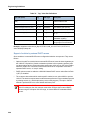
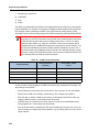
Revised Embedded Music On Hold capacities for CX/CXi controllers (Table 41 on
page 124).
3
Engineering Guidelines
•
Updated IP port usage (Table 80 on page 272)
•
Clarified bandwidth requirements for SRTP encrypted voice streams (page 339).
Engineering Guidelines for older releases can be found in the Legacy/Older Products section
on the
Note: Information specific to Releases prior to MCD 6.0 that has been superceded by
changes in the current release, or that is no longer relevant for other reasons, has been
removed from this document. Engineering Guidelines for these older releases are still
available on the Mitel eDocs web site. See the next section for details
About the MiVoice Business Documentation Set
Documents for MiVoice Business and other Mitel® products are available on the Mitel eDocs
web site (edocs.mitel.com) to anyone with a Mitel Online account.
Note: PDF versions of end user documents (such as telephone user guides) can be
viewed and downloaded without a Mitel Online account.
The following guides provide complete information about the MiVoice Business:
•
Technician's Handbook: installation, upgrade, maintenance, troubleshooting instructions.
•
Hardware Technical Reference Manual: hardware specifications.
•
Configuration Tool Online Help: procedures on configuring the 3300 ICP with a default
database, and migrating SX-2000®, 3200 ICP, and 3800 Wireless Application Gateway
databases to a 3300 ICP.
•
System Administration Tool Help for MiVoice Business: programming, maintenance, and
troubleshooting.
•
3300 ICP Resiliency guide: overview of the Mitel Resiliency solution and the tools to
understand, plan, and implement a resilient network.
•
General Information Guide: General product overview including deployments, architecture,
products and features.
•
Safety Instructions: to be read BEFORE installation.
•
Clustering Design and Implementation (Download document and associated .xls files: Cluster planning and installation guide for migrating to and using SDS sharing, Multi-Node
Management .
•
Site Planning Guide: Product installation checklist.
Additional information can also be found under the "Mitel 3300 IP Communications Platform"
heading on Mitel Online, including:
4
•
Mitel 3300 ICP Controllers Data Sheet: Platform capability list.
•
SX-200 to 3300 ICP Migration Information
About This Document
•
Current Product Briefs: Notes on current releases
•
White Papers: Reliability (MTTF and MTBF) and Availability information
5
Engineering Guidelines
System Management Tools
The System Administration Tool, the Group Administration Tool and the Desktop Tool are GUI
based tools for configuring and administering MiVoice Business and MiVoice IP Phones. The
System Management Tools are accessed via an internet browser.
For MCD Release 6.0 Internet Explorer (IE) Version 8.0 is supported, other web browsers (such
as Firefox, Navigator, Google Chrome) are not supported.
For MiVoice Business Release 7.0 Internet Explorer Version 9 or later and Mozilla Firefox 17.0
are supported.
Only the System Administration Tool supports Firefox; the other tools (Group Admin and
Desktop Tools) require IE.
About the MiVoice Business System
Engineering Tool
Most systems can be engineered, in terms of their hardware components, from the fairly simple
rules presented in these guidelines. The Mitel Sales Workbench (MSW) builds in most of these
rules. When an installation requires a system that is complex or close to some operating limits,
contact Mitel's Customer Engineering Service. The customer service engineers have access
to the System Engineering Tool (SET), which can analyze a system and determine in much
greater detail the overall hardware requirements and expected performance. This tool will
identify the modules required, traffic limits, and the processor Performance Index (PI).
The SET is developed using Microsoft Excel 2003, and tested in Excel 2007. It is no longer
supported in older versions (Excel 97 and Excel 2000), nor does it work in Open Office.
6
CHAPTER 2
SYSTEM OVERVIEW
System Overview
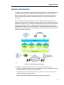
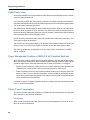
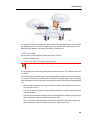
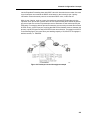
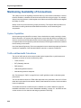
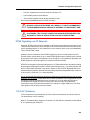
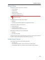
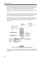
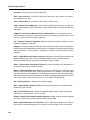
System Architecture
The 3300 ICP is built upon Mitel’s Data Integrated Voice Applications™ architecture delivering
sophisticated call management, applications and desktop solutions to businesses. Mitel
delivers a highly scalable, resilient, and robust call control that fully utilizes the power of IP
while fully supporting the traditional TDM-based telephony for legacy devices and PSTN
connectivity.
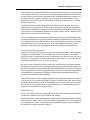
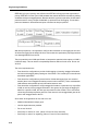
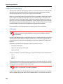
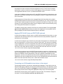
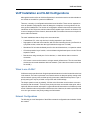
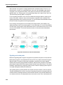
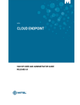
Mitel’s architecture uses the IP network to connect IP telephony devices and provides a
supplementary TDM (time division multiplexing) subsystem to switch calls between traditional
telephone devices (Figure 1). The 3300 ICP has the advantage of being able to optimally switch
both types of traffic, IP or TDM. The 3300 ICP provides native call setup, tear down, and
signalling between Ethernet IP-connected telephones. For traditional telephony, such as POTS
and PSTN trunks, call handling is also handled natively by the 3300 ICP through a conventional
TDM circuit-switched subsystem.
Figure 1: 3300 ICP System Architecture
This ability to use two different switching techniques simultaneously means that
•
All traffic is switched with minimum conversion between packet and traditional telephony
to provide optimum voice quality in all call scenarios.
•
Embedded gateway functionality is required only between the IP and non-IP networks
optimizing the use of system resources.
•
Migration from traditional PBX to IP telephony is seamless and efficient.
9
Engineering Guidelines
MiVoice Business Controller
The MiVoice Business controller provides the voice, signalling, central processing, and
communications resources for the system. There are several controller configurations
supported for release MiVoice Business 7.0 including 3300 ICP Controllers and industry
standard servers:
•
AX controller with 512 MB memory
•
CX/CXi controller with 512 MB memory (no longer manufactured)
•
CX-II / CXi-II controller with 512 MB or 1024 MB memory
•
LX controller with 512 MB memory (no longer manufactured)
•
MXe Base or Expanded controller (no longer manufactured)
•
MXe II Base or Expanded controller (no longer manufactured)
•
MXe III Base or Expanded controller with 512MB or 1024MB memory
•
MXe Server (no longer manufactured)
•
MiVoice Business for Industry Standard Servers
•
MiVoice Business Multi-instance
•
Virtual MiVoice Business
Note: Refer to the Hardware Technical Reference Manual, available at Mitel Online, for
further details on the system components.
The functionality of the 3300 controller can be expanded by installing optional modules such
as: Digital Signal Processors (DSP), Dual Fiber Interface Modules (FIM), Dual T1/E1 Framers,
Quad BRI Framers, and T1/E1 Combo Modules.
Processor Speeds
The processors used in the 3300 ICP family are optimized for use in high-end communications
equipment. Each unit has both a high-performance general purpose processor core and a
RISC-based communications processor module. The clock speeds listed in this documentation
refer to the external speeds of the devices and should not be compared to the internal clock
speeds used to describe the x86 family of desktop processors.
The MXe Server has a third processor, an X86 type. This processor is used for call control while
the other processors are used for real-time process control (RTC) and TDM to IP conversion
(E2T). The new processor uses a much higher clock speed (2 GHz) , but the performance of
the MXe Server is also improved by the sharing of the work load among more processors.
•
10
The pure server configurations of MiVoice Business (MiVoice Business for ISS,
MiVoice Business Multi-instance, and Virtual MiVoice Business) use X86 processors exclusively, with no dedicated processors (either CISC, RISC, or DSP based) for any of the
TDM functions. The CPUs in these servers will be multi-core, and usually there will be
multiple processors in each server.
System Overview
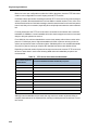
Supported Countries
During the installation process the MiVoice Business system can be configured for operation
in a particular country or region. The Embedded System Management interface (ESM) allows
the installer to choose the most appropriate country or region from a list of supported countries
and regions. Country/region support includes
•
language support for set display prompts
•
loss level plans and tone plans that have been specifically designed for the selected country
•
analog station and trunk port parameters that have been specifically designed for the selected country.
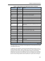
Currently supported countries and regions include
•
Australia
•
Brazil
•
China
•
France
•
Germany
•
Italy
•
Latin America (Argentina, Chile, Mexico)
•
Netherlands
•
New Zealand
•
North America (Canada, USA)
•
Portugal
•
Spain
•
UK.
In some cases MiVoice Business can be deployed in countries that are not included in the
above list. In these cases, regional office personnel will be able to suggest the country selection
that will provide the best transmission performance.
Note: Refer to the Hardware Technical Reference Manual, available at Mitel Online, for
complete tone plans and loss tables for each of these countries.
11
Engineering Guidelines
12
CHAPTER 3
TYPICAL CONFIGURATIONS
Typical Configurations
System Configurations
The MiVoice Business product line includes a number of platforms, IP phones, and applications.
Each platform is designed for a different business segment and size, but each contains a number
of common components. The main difference between the units is the quantity of components
contained in each.
The units are flexible and can be used in a number of different configurations, for example:
•
IP-PBX with phones, Voice Mail, and PSTN gateway
•
Standalone controller, in conjunction with other units
•
Standalone PSTN gateway
•
Standalone Voice Mail
•
Standalone wireless gateway
•
Standalone IP network gateway
•
Standalone Teleworker gateway
•
Resiliency backup controller
•
TDM controller for legacy interfaces (e.g. SX-2000 Light Peripheral and DSU cabinets).
Note: Refer to “Migrate SX-2000 PBX Hardware” in the 3300 ICP Technician’s
Handbook for detailed instructions.
The use of the LAN infrastructure and IP networking allows the units to be installed and used
in a number of different configurations. It also allows for a more distributed architecture and
dispersal of equipment compared to a more traditional central TDM PBX system.
MiVoice Business has a reliable, mature call control with a large feature set enabling multiple
integration possibilities with an existing installation.
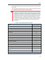
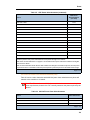
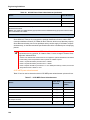
The remainder of this chapter describes typical configurations, and provides some sample
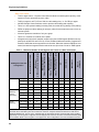
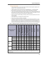
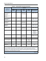
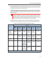
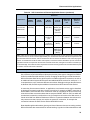
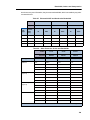
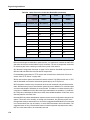
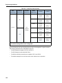
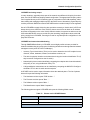
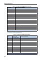
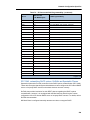
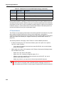
configurations. “Configuration Tables” on page 30 show the maximum capacity for each feature
or resource for each type of controller.
For more information on the following topics that may affect the system configuration, see:
•
3300 ICP Technician’s Handbook for Slot Number convention
•
3300 ICP Hardware Technical Reference Manual for external interfaces and external TDM
interfaces.
15
Engineering Guidelines
Typical Installation Configurations
The MiVoice Business platorm can be designed into different network configurations to suit the
organization of the enterprise. See the following examples for an illustration of how the
organization of the enterprise affects the overall network and unit configurations:
•
“Multiple Units System” on page 16
•
“Distributed System” on page 16
•
“Hybrid System” on page 18
In the descriptions below, a unit is considered to be a 3300 ICP with a particular configuration
and is part of the overall telephony system.
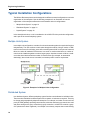
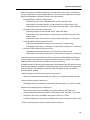
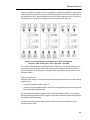
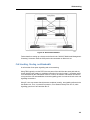
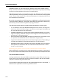
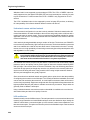
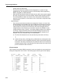
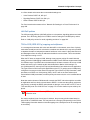
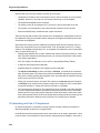
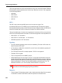
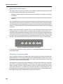
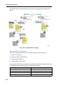
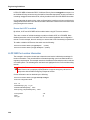
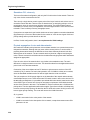
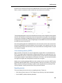
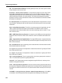
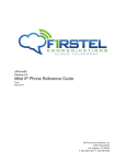
Multiple Units System
In a multiple unit configuration, a number of units are clustered together, but each unit functions
independently. The units connect to each other through the network, using IP trunks or TDM
trunks. In the event of a unit failure, some of the overall system will fail. In the event of a network
failure, the units still maintain PSTN access. In a small- or medium-sized office, a number of
units could be installed together to make a larger system. Another scenario could be a smallor medium-sized business with a number of branch offices (for example, an automobile
dealership), where local access is needed, but intershop traffic is also a requirement.
Figure 2: Example of a Multiple Units Configuration
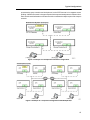
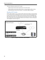
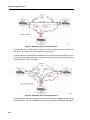
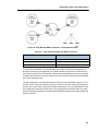
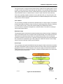
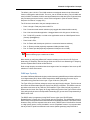
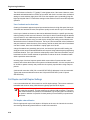
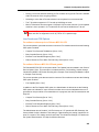
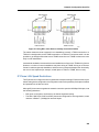
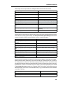
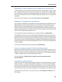
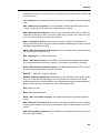
Distributed System
In a distributed system, different telephony system functions are dedicated to individual units.
These are then distributed to different parts of the network, or business as required. This may
be a large and geographically dispersed enterprise. For example, a number of units could act
purely as TDM gateways providing central access, with other units acting as central voice mail
and others acting as the group controllers (a group controller is a 3300 ICP to which a group
of IP phones have been registered). An example is a university campus where each building
16
Typical Configurations
possesses the group controller and local phones, but the PSTN access is in a separate secure
building. A different scenario is a large enterprise with corporate headquarters in different cities.
Each would have distributed trunk units and could be considered multiple copies of the campus
scenario.
Figure 3: Example of a Campus Environment Configuration
Figure 4: Example of a Corporate Configuration with Multiple HQs
17
Engineering Guidelines
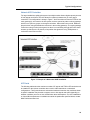
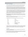
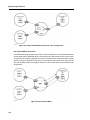
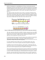
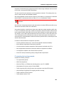
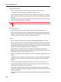
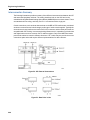
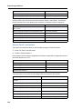
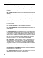
Hybrid System
A Hybrid system combines both of the previous scenarios and involves a distributed system
for a headquarters and combined units for remote branch offices. The branch office has access
to corporate PSTN access as well as local access through the local group controller. In the
event the WAN link is lost, the separate sites can still operate as independent units.
Figure 5: Example of a Hybrid Configuration
18
Typical Configurations
Sample 3300 ICP Configurations
The sections below describe sample configurations:
•
“The 3300 ICP as a Trunk Gateway” on page 19
•
“The 3300 ICP as a Trunk Tandem” on page 20
•
“MiVoice Business, 3300 ICP and ACD” on page 20
•
“The 3300 ICP as a Dedicated Voice Mail Server” on page 29
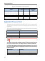
The 3300 ICP as a Trunk Gateway
If the 3300 ICP is used as a trunk gateway, the unit will act purely as a TDM-to-IP gateway. It
will not have IP phones registered. If phones are registered, then the number of trunks that can
be handled will be reduced. Other controllers will have large numbers of phones connected to
them but no TDM trunks (group controller or user gateway).
The limiting factor on a trunk gateway will usually be the number of E2T channels available on
it. If a controller that is used as a trunk gateway also acts as a resilient backup for all or some
of the IP phones on a group controller the trunk capacity will not necessarily be affected. The
assumption is that when the phones fail over to this controller there will be much less IP trunk
traffic to the other controllers in the network.
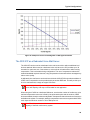
The trunks are expected to be busy 75% to 100% of the time. Therefore the number of trunks
and the number of E2T channels are directly linked. The maximum number of trunk channels
is about 120 channels, or 4 E1 / 5 T1 links on the large controllers (to match the 128 E2T
channels), and 60 channels for the smaller units (64 E2T channels).
In the MXE Controller 192 Gateway, the maximum number of trunks would be 180 E1 trunks
(6 links) or 192 T1 trunks (8 links). If SRTP is enabled the maximum number of E2T channels
is reduces to 150 (5 E1 links or 6 T1 links).
Note: For purposes of this discussion, the term TDM trunks refers to digital (T1/E1)
trunks only, although LS trunks could be used to increase the trunk quantity to exactly
match the available E2T channels.
Few other device channels, such as voice mail or embedded RADs, should be programmed.
There should be no other TDM connectivity. One exception is Music-on-Hold. There are other
application scenarios, such as resilient/networked ACD configurations, where RADs would be
set up on the trunk gateway (see “MiVoice Business, 3300 ICP and ACD” on page 20).
See “Trunking gateway working example” on page 188 for an example of the calculations
needed.
19
Engineering Guidelines
The 3300 ICP as a Trunk Tandem
When the 3300 ICP acts as a Trunk Tandem, it functions similar to that described for the gateway
unit. Typically, this configuration is applied where there is already an established (TDM) PBX
network where the ICP units are being used for toll-bypass, or as an alternative route to the PSTN.
As with the gateway unit, the 3300 ICP does not have end users directly connected. The heavy
performance load and/or the limited number of E2T channels will restrict the capacity of this
configuration. The connections for a tandem configuration may be TDM trunk to TDM trunk, IP
trunk to TDM trunk, SIP trunk to TDM trunk, or IP trunk to SIP trunk. The first three require a
TDM gateway and are limited by the number of TDM channels available (same as the TDM
gateway), but the last configuration does not and will be limited only by performance.
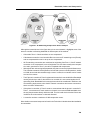
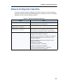
MiVoice Business, 3300 ICP and ACD
A typical call center (ACD) installation consists of several separate components which integrate
to make up the complete system.
•
ACD controller may be either MiVoice Business on a server platform (MXe Server,
MiVoice Business for ISS, MiVoice Business Multi-instance, Virtual MiVoice Business) or
one of several 3300 ICP platforms. This can either be all functions in one standalone
controller, or a network of trunk gateways and agent controllers.
•
Contact Center Manager (CCM), for reporting and some interactive functions.
•
Interactive Voice Response (IVR), the auto-attendant function, which may also act as a
source for recorded announcements (RADs).
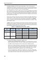
When MiVoice Business and 3300 ICP are used for ACD applications, there are several factors
that must be considered in determining the capacity limitations. The performance of the
controller will be limited because of the high number of calls made in comparison to a system
with normal office traffic. In addition, the performance cost of each call will be much higher, to
account for IVR interaction in the call (including RAD playback) and for agent skills groups and
multiple path queues. Because agents are connected to trunks most of the time, the number
of E2T channels will be critical to the number of agents and/or trunks that can be supported.
It is expected that most MiVoice Business and 3300 ICP installations will use IP phones for the
agents but it is also possible with some 3300 ICP controllers to use TDM phones (DNIC or
ONS). Where they can be used, TDM phones are included with IP phones in the total agent
quantity. In some cases External Hot Desk Agents (EHDA) may be used, and these will add
significant overhead to the performance of the system, reducing the total number of agents
supported. In a standalone system with a 3300 ICP controller, the number of agents with IP
phones is limited by the number of E2T channels available, but since DNIC and ONS phones
do not require E2T resources to connect to a TDM trunk, it is possible to put more of them in
a standalone system. Conversely, an agent group controller connected to multiple trunk
gateways can handle more IP phones than TDM phones since the IP phones in this case do
not need the E2T resources and the TDM phones do.
SIP trunks provide an alternate means of connecting to the PSTN. These will be used most often
with MiVoice Business for ISS controllers, although it is also possible to use them with 3300 ICP
controllers.
20
Typical Configurations
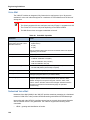
RAD sources may be embedded (using the voice mail and/or music ports) or off-board (for
example, Mitel Contact Center Intelligent Queue). In the networked configurations, the RAD
playback and distribution should be located on the trunk gateway.
•
•
•
•
Embedded RAD in 3300 ICP (TDM source)
-
RAD plays directly into the TDM switch fabric (no E2T channels used).
-
RAD stream is connected directly to n output channels for TDM trunks (no E2T).
-
RAD stream uses n E2T channels to connect to SIP trunks (total = n E2T channels).
External IP RAD in 3300 ICP (TDM source)
-
RAD plays through one E2T channel into the TDM switch fabric.
-
RAD stream is connected directly to n output channels for TDM trunks (only 1 E2T
channel used).
-
RAD stream uses n E2T channels to connect to SIP trunks (total = n+1 channels).
Embedded RAD in MiVoice Business for ISS
-
RAD plays within Media Server portion of the controller (1 channel used)
-
RAD stream is multi-cast to n channels to connect to SIP trunks (total = n+1 channels).
External IP RAD in MiVoice Business for ISS
-
RAD plays into Media Server portion of the controller (1 channel used).
-
RAD stream is multi-cast to n channels to connect to SIP trunks (total = n+1 channels).
Conference resources are needed in the ACD environment for Silent Monitor and Whisper
Coach (availabe on x86 platforms only) and consultation calls by the agents. In the network
installations these resources are provided on the agent controller(s).
IP (MiNet) phones, SIP phones (including MiCollab Client softphones and SIP clients on mobile
smart phones), digital phones (DNIC) and analogue phones may be used for ACD agents under
various conditions. The following is a summary of how ACD agents may be connected to
MiVoice Business systems.
Traditional agents or Hot Desk ACD agents are supported on:
•
MiVoice IP Phones directly connected to the system, or via a MiVoice Border Gateway
Traditional agents only are supported on:
•
TDM digital phones as extensions to the MiVoice Business systems, e.g. DNIC or ISDN
External Hot Desking Agents are supported on:
•
Mobile phones that connect as EHDA to the system via BRI or PRI TDM trunks
•
Analogue phones that connect as EHDA to the system via BRI, PRI TDM, or IP Trunks*
•
SIP phones that connect as EHDA to the system via SIP or IP Trunks*
•
Third Party PBX phones that connect as EHDA to the system via PRI, SIP, QSIG Trunks*
* Refer to CCS Deployment Guide for further detailed restrictions.
21
Engineering Guidelines
The MiVoice Business systems do NOT support:
•
Traditional agents and Hot Desk agents active on the same system
•
Traditional agents and Hot Desk agents directly or natively logged into SIP or Analog
endpoints (directly connected to the system, or via a MiVoice Border Gateway)
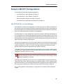
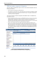
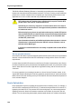
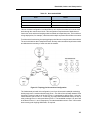
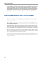
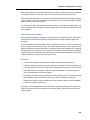
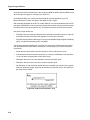
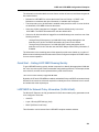
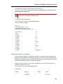
Standalone ACD Controller
Smaller ACD installations will use a single controller with all trunks, agents, groups and paths
on it. The IVR and Call Centre Manager are both connected to this controller (through the local
network), as are the agents. The calls will come into the call centre from the PSTN through
either TDM or SIP trunks, will be routed through the IVR system and queued to a path. RADs
may be played either from the embedded resources on the controller, or from the IVR system.
This configuration is shown in Figure 6.
Figure 6: Example of a Standalone ACD installation
22
Typical Configurations
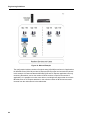
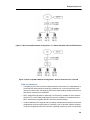
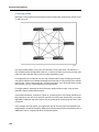
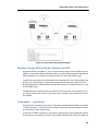
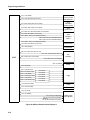
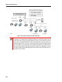
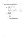
Network ACD Controllers
For large installations, splitting the system into multiple nodes allows a higher capacity in terms
of both agents and trunks. This also allows for resiliency between two (or more) agent
controllers. This configuration is shown in Figure 7. Here the calls enter from the PSTN on the
trunk gateway(s), are routed to the IVR system, and are queued to paths on those gateways
which in turn queue to groups on the agent controllers. When callers are on hold, RADs are
played to them using the distribution resources in the trunking gateways. The agent gateways
control the routing of calls to the agents, but there is no streaming through them since the IP
streams go directly to the IP phones, except when the agents are using TDM phones or
conference resources are used.
Figure 7: Example of a Networked ACD Installation
ACD limits
The following tables show the maximum number of IP agents and TDM or SIP trunks that can
be installed on the various controllers when used in either standalone or networked
configurations. The figures shown are a theoretical maximum based on the conditions shown.
A specific installation may be able to support more or less agents and traffic depending on
whether conditions are more or less stressful than these assumptions. For ACD installations
on Virtual MiVoice Business or installations outside the parameters specified below, contact
Mitel Professional Services.
23
Engineering Guidelines
Basic Call Center
•
Trunk to agent ratio is 1.5 (lower trunk ratios will allow increased system capacity, at the
expense of more rejected (busy tone) calls).
•
Traffic per agent is at 27 CCS and 120 sec call handling time, i.e. 30 CPH per agent.
•
No Mitel Contact Center Solutions used to provide call handling and reporting.
•
There is no IVR system handling incoming calls, thus calls will ring directly to the path(s).
•
RADs are played to callers waiting in queue(s), either from internal resources or from an
external system.
•
All active agents are members of only one group.
•
There is no overflow or interflow on the paths.
•
All agents are local to their controller except in the rows for EHD agents (EHDA is not supported prior to MCD 5.0 and CCS 6.0). If used, EHDA will affect the number of agents and
amount of traffic that can be supported on a controller. When the maximum EHDA are connected, the total local agents must be reduced to zero (see chart of Local vs. EHD Agents.
MiVoice Business for ISS
MXe Server
& MiVoice Business Multi-instance
MiVoice Business
VMware Virtual Appliance (150)
MiVoice Business
VMware Virtual Appliance (1500)
MiVoice Business
VMware Virtual Appliance (2500)
AX
CX II / CXi II
MXe III base
MXe III
expanded
Table 1: Maximum Number of ACD Agents and Trunks in a Basic Call Center
Total agents
500
300
30
150
250
50
50
60
90
EHD agents
100
100
10
50
100
10
10
10
40
TDM trunks
0
0
0
0
0
60
60
90
180
SIP trunks
750
450
45
150
375
75
75
90
300
Total agents
700
350
30
200
350
50
50
100
150
EHD agents
200
100
10
100
200
10
10
10
40
TDM trunks
0
0
0
0
0
0
0
0
0
SIP trunks
0
0
0
0
0
0
0
0
0
Total agents
0
0
0
0
0
0
0
0
0
TDM trunks
0
0
0
0
0
60
60
60
120
SIP trunks
525
300
60
300
450
75
75
90
150
ACD Agent and Trunk
Configuration
Standalone
User
Gateway
(group
controller)
Trunk
Gateway
Note: Because the AX is primarily an ONS and LS gateway, it would not normally be used in an ACD application.
The MXe Server is limited by E2T and conference resources compared to MiVoice Business for ISS with its
attached Media Server. The AX, CX II, and MXe base are also limited by E2T and other DSP resources.Mitel
proprietary voice encryption is supported in ACD deployments. However, due to the increased load SRTP places
on the solution SRTP voice encryption is not supported in ACD configurations and must be disabled via ESM.
24
Typical Configurations
Advanced Call Center
•
Trunk to agent ratio is 1.5 (lower trunk ratios will allow increased system capacity, at the
expense of more rejected (busy tone) calls).
•
Traffic per agent is at 27 CCS and 120 sec call handling time, i.e. 30 CPH per agent.
•
Mitel Contact Center Solutions 6.0 is used to provide call handling and reporting.
•
There is an IVR system handling incoming calls. With no IVR, calls will ring directly to the
path(s) with less overhead, but there is less functionality in terms of call handling. The IVR
must be on the path controller (trunk gateway) for networked ACD.
•
RADs are played to callers waiting in queue(s), either from internal resources or from an
external system.
•
Active agents are in an average of five groups or less.
•
There is one overflow or interflow on the paths.
•
All agents are local to their controller except in the rows for EHD agents (EHDA is not supported prior to MCD 5.0 and CCS 6.0). If used, EHDA will affect the number of agents and
amount of traffic that can be supported on a controller. When the maximum EHDA are connected, the total local agents must be reduced to zero (see chart of Local vs. EHD Agents)
.
MiVoice Business for ISS
MXe Server
& MiVoice Business Multi-instance
MiVoice Business
VMware Virtual Appliance (150)
MiVoice Business
VMware Virtual Appliance (1500)
MiVoice Business
VMware Virtual Appliance (2500)
AX
CX II / CXi II
MXe III base
MXe III
expanded
Table 2: Maximum Number of ACD Agents and Trunks in an Advanced Call Center
Total agents
350
200
30
100
175
40
40
50
90
EHD agents
100
100
10
50
100
10
10
10
40
TDM trunks
0
0
0
0
0
60
60
75
135
SIP trunks
525
300
45
150
250
75
75
90
150
Total agents
700
350
30
200
350
50
50
80
150
EHD agents
200
100
10
100
200
10
10
10
40
TDM trunks
0
0
0
0
0
0
0
0
0
SIP trunks
0
0
0
0
0
0
0
0
0
Total agents
0
0
0
0
0
0
0
0
0
TDM trunks
0
0
0
0
0
60
60
60
120
SIP trunks
525
300
60
250
350
75
75
90
150
ACD Agent and Trunk
Configuration
Standalone
User
Gateway
(group
controller)
Trunk
Gateway
Note: Mitel proprietary voice encryption is supported in ACD deployments. However, due to the increased load
SRTP places on the solution SRTP voice encryption is not supported in ACD configurations and must be
disabled via ESM.
25
Engineering Guidelines
In the standalone configuration, adding more groups for the agents or allowing overflow on the
paths will both add a processing load for each call, and will therefore reduce the capacity of
the system. In the networked configuration, the agent controller has been relieved of the
processing load for the IVR, so the nominal call capacity increases significantly from that of a
standalone system. Multiple agent groups and path overflows still affect this node and reduce
its capacity. The path controller (PSTN gateway) is still carrying the IVR load, but it is not dealing
with the agent groups. However, the path overflows are more restrictive than on the single node,
and will reduce the capacity of the node significantly.
The System Engineering Tool deals with all of these conditions, and must be used when
analyzing any ACD configuration, including older controllers which do not fit within the limits
shown in the above table. Contact Professional Services for assistance for any configuration with:
26
•
more agents and/or trunks
•
different traffic pattern
•
more agent groups
•
greater path overflow and interflow
•
additional or alternate applications attached.
•
any requirement for call centers with MiVoice Business Multi-instance or Virtual
MiVoice Business.
Typical Configurations
Active agents vs. traffic
The maximum number of agents shown in the above tables is based on each agent handling
an average of 30 CPH, corresponding to an average total call handling time (CHT) of 120
seconds, including work timer. If the call traffic is a different rate, the number of active agents
that can be supported on a controller will change. The following tables show typical numbers
for several representative configurations. In each case we are still assuming agents in an
average of 5 groups, and one overflow per path
Table 3: Active Agents on ISS Standalone Controller
Agents
CHT (sec)
CPH
CPH/agent
100
34
10500
105
350
120
10500
40
700
240
10500
15
1050
360
10500
10
Table 4: Active Agents on ISS Agent Controller
Agents
CHT (sec)
CPH
CPH/agent
100
30
21000
210
350
90
21000
60
700
120
21000
30
1050
180
21000
20
1400
240
21000
15
Table 5: Active Agents on MXe-III Standalone Controller (with PRI)
Agents
CHT (sec)
CPH
CPH/agent
10
30
1200
120
20
60
1200
60
30
120
1200
30
40
180
1200
20
60
240
1200
15
80
300
1200
12
100
360
1200
10
Table 6: Active Agents on MXe-III Agent Controller
Agents
CHT (sec)
CPH
CPH/agent
25
30
3000
120
50
60
3000
60
75
90
3000
40
27
Engineering Guidelines
Table 6: Active Agents on MXe-III Agent Controller
Agents
CHT (sec)
CPH
CPH/agent
100
120
3000
30
150
180
3000
20
200
240
3000
15
250
300
3000
12
300
360
3000
10
Local agents vs. EHD agents
As stated previously, when EHDA is used for some or all of the agents, the total number of
agents that can be supported on a controller is reduced. Table 7 is a summary of the maximum
number of agents and EHD agents on the various platforms for an agent controller in an
advanced call center configuration. Figure 8 shows how the number of local and external hot
desk agents must be balanced on an agent controller (example shown is for MiVoice Business
for ISS. The same principle must be used for any other controller configuration.
Table 7: Active Agents on Agent Controller in Advanced Call Center
Platform
Maximum Agents
Maximum EHD Agents
MiVoice Business for ISS
700
200
MXe Server (& MiVoice Business
Multi-instance)
350
100
Virtual MiVoice Business (150)
30
10
Virtual MiVoice Business (2500)
350
200
AX
50
10
CX II / CXi II
50
10
MXe III (base)
80
10
MXe III (expanded)
150
40
28
Typical Configurations
Figure 8: Example of Local vs. EHD Agents on ISS Agent Controller
The 3300 ICP as a Dedicated Voice Mail Server
The 3300 ICP can be used as a dedicated voice mail server with or without additional end
devices attached. When used as a dedicated voice mail server, the ICP provides up to 30
channels for continuous use. Connections to voice mail can be made with or without using
compression. This is selectable during configuration. The use of compression reduces the
network bandwidth required. However, using compression to leave and retrieve messages may
reduce voice quality.
A dedicated voice mail server can be achieved with the 3300 ICP MX unit with the addition of
a DSP card. Compression can be provided with yet another DSP card. This will provide up to
30 voice mail sessions, enough to support 700 users.
Note: Using voice mail ports to support auto attendant functions reduces the overall
voice mail capacity, and may not be suitable for this application.
When using the CX/CXi as a dedicated VM server, note that the number of conference, voice
mail and compression resources is fixed by the purchased option and the number of DSP
devices available; the other values are adjustable. Compression alters the number of resources
available to the system. For example, adding 8 compression resources to a system with 4 DSPs
total, drops the maximum number of Voice Mail ports to 4.
Note: The AX controller should not be used as a voice mail server because of the limited
capacity of the flash card memory system.
29
Engineering Guidelines
When determining network bandwidth, consider voice mail sessions as being active 100% of
the time. The number of voice mail sessions determines the bandwidth required. With G.711
voice streams and 30 active sessions, a minimum of 4.0 Mbps must be provided:
(30 x 96.8 kbps + 10% (signalling)) / 80% = 4.0 Mbps
Where the unit is used as a dedicated voice mail server, consider the number of other functions
provided on the box. As more voice mail sessions are activated the number of IP phones that
can be handled decreases. Typically 30 VM sessions and 700 users are in direct opposition.
Consider multiple units beyond approximately 400 users and 20 voice mail sessions.
Configuration Tables
The following tables show the maximum capacity for each feature or resource in each type of
controller. You cannot configure a system to support all maximum values at the same time.
30
•
IP devices includes all telephones and all applications which emulate telephones, including
SIP phones.
•
TDM devices includes all ONS/OPS and DNIC sets but not analog or digital trunks.
•
Compression channels includes only those channels that are necessary within the ICP to
connect TDM ports to IP trunks. Most IP sets can stream compressed audio to another IP
port without using any ICP resources. Those that can’t, simply stream uncompressed audio
(the call is not routed using internal ICP resources).
•
Digital links refers to embedded BRI (4 links, 8 lines or trunks per module), embedded
T1/E1 (1 link, 23/24/30 trunks, or 2 links, 46/48/60 trunks per module), or external T1/E1
(2 links, 46/49/60 trunks per NSU cabinet). It does not include the external BRI NSU, which
is an adapter that can be added behind any E1 link at up to 15 trunks per cabinet.
Typical Configurations
MXe Server, Virtual MiVoice Business, MiVoice Business for ISS, and
MiVoice Business Multi-instance
Note: Other limits besides those in the following table may apply to Virtual
MiVoice Business and MiVoice Business for ISS depending on the deployment. Consult
the Virtual MiVoice Business and MiVoice Business for ISS Engineering Guidelines for
more information.
Table 8: Maximum MXe Server / Virtual MiVoice Business / MiVoice Business for ISS /
MiVoice Business Multi-instance configuration
Feature /
Resource
Value / Quantity
Notes
Call Control
Processor (x86)
2.0 GHz (MXe Server)
This processor runs only call control and passes other real time
functions and E2T to the other processors. May be higher
speed on MiVoice Business for ISS, VMware Virtual Appliance,
and Multi-instance platforms, depending on server chosen.
RTC processor
533 MHz
Runs Call Control on 3300 ICP appliances. This function is
performed by the x86 processor on MiVoice Business for ISS,
VMware Virtual Appliance, and Multi-instance platforms.
E2T processor
533 MHz
This processor is used to increase E2T capacity, sharing the
load. This function is performed by the Media Server on
MiVoice Business for ISS, VMware Virtual Appliance, and
Multi-instance platforms.
Memory (RAM)
512 MB (MXe Server)
For other platforms, see their respective Engineering
Guidelines.
IP Users (including
SIP users)
2500/5000
The lower number of devices can be supported with no
Engineering Rules. Going above this number will force tradeoffs
between set types, user quantity, and applications. Mitel
recommends using the System Engineering Tool.
2.26 GHz (min for ISS)
Additional limits may apply with SIP-TLS. See “SIP Phones and
use of TLS (SIP-TLS)” on page 44.
TDM Devices
0
TDM devices are not supported on this controller.
Total Devices
3000/5000
The lower number is for display sets (e.g. 5330, 5340, 5360)
and the higher number is for standard sets, including generic
SIP sets.
ACD users
(licensed agents)
2100
IP users only. See Table 1 for Active Agents allowed.
Echo canceller
channels/
IP gateway (E2T)
256 (MXe Server)
Conference
channels
128 (MXe Server)
1000 (MiVoice Business
for ISS)
600 (MiVoice Business
for ISS)
Each conference may have from 3 to 8 members, but the total
number of conferees cannot exceed the allowed maximum.
Page 1 of 2
31
Engineering Guidelines
Table 8: Maximum MXe Server / Virtual MiVoice Business / MiVoice Business for ISS /
MiVoice Business Multi-instance configuration (continued)
Feature /
Resource
Value / Quantity
Notes
Voice Mail
0
Voice mail must be an external application on MXe Server and
MiVoice Business for ISS.
Compression
channels
256
G.729a compression is not a standard offering on base
systems. Additional DSP resources are needed to achieve the
value shown in the MXe Server. Compression is added in
blocks of 8 bidirectional channels on Quad DSP and DSP II
modules only. In MiVoice Business for ISS, VMware Virtual
Appliance, and Multi-instance platforms compression is a
licensed function in the Media Server.
Record-a-Call
Not applicable
The number of sessions are limited by the available E2T
channels, conference channels, and external voice mail ports.
CIM ports
0
The 4 CIM ports on the front panel of the MXe Server are not
enabled, and they do not exist on MiVoice Business for ISS,
VMware Virtual Appliance, and Multi-instance platforms.
ASUs supported
0
LS trunks
0
There is no internal ASU (AMB) in the MXe Server,
MiVoice Business for ISS, VMware Virtual Appliance, and
Multi-instance platforms.
IP networking
Yes
The system can support a maximum of 2000 programmed IP
trunks, but the number which can be used at any one time will
be limited by other resources.
MMC modules
(installed slots,
MXe Server only)
Echo Canceller (3,4,5,6) Two echo canceller modules must be installed; the other slots
Quad DSP (1,2,3,4, 5.6) are available for DSP modules. In MiVoice Business for ISS,
VMware Virtual Appliance, and Multi-instance platforms these
DSP II (4,5,6)
functions are performed by the Media Server.
Digital links
0
Peripheral cabinet
0
NSU/DSU cabinet
0
Page 2 of 2
32
Typical Configurations
AX Controller
Table 9: Maximum AX configuration
Feature /
Resource
Value / Quantity
RTC processor
450 MHz
E2T processor
N/A
Memory (RAM)
512MB
IP Users and
Devices (including
SIP users)
100/300
Maximum IP devices or users. The lower number of
devices/users can be supported on any system at normal
office traffic. The larger number can be supported on a system
with 512MB of memory and only at reduced traffic (2-3 CCS)
in hospitality applications. SIP devices are part of the same
pool of IP sets that can register with a controller.
TDM Devices
288
ONS devices only. DNIC devices are not supported on the AX
controller.
Total devices
300/575
Maximum total devices, IP and TDM combined. The lower
number of devices can be supported on any system at normal
office traffic. The larger number can be supported on a system
with 512MB of memory and only at reduced traffic (2-3 CCS)
in hospitality applications.
ACD users
(active agents)
50
IP only
Echo cancelleor
channels/
IP gateway (E2T)
40/128
The default channels provided by the on-board DSPs are
increased with an EC module installed.
Conference
channels
64
The maximum number of conference sessions is 21 and the
maximum number of conferees per session is 8. The
combination cannot exceed 64.
Voice Mail
20
Voice mail is limited to 20 ports on the AX. Flash 1 must be
upgraded to the 4 GByte Flash card.
Compression
channels
64
Requires installation of Quad DSP module or DSP II module.
T.38
16
DSP-II is required for T.38 functionality.
Record-a-Call
8
Every Record-a-Call session uses a conference resource and
a voice mail session from the available pool. The maximum
number of simultaneous sessions supported is 8, but may be
limited to less than this by the available resources.
CIM ports
0
The quad CIM is not supported on the AX.
ASUs supported
0
ASUs are not supported on the AX.
LS trunks
48
IP networking
Yes
Notes
The AX uses a single processor for both RTC and E2T
functions.
The system can support a maximum of 2000 programmed IP
trunks, but the number which can be used at any one time will
be limited by other resources.
Page 1 of 2
33
Engineering Guidelines
Table 9: Maximum AX configuration (continued)
Feature /
Resource
Value / Quantity
Notes
MMC modules
(installed slots)
Quad DSP (int, ext)
Echo Canceller (int, ext)
Dual T1/E1 (ext)
T1/E1 Combo (ext)
Quad BRI (ext)
Dual FIM (ext)
DSP II (int, ext)
Modules may be installed in the internal or external locations
as shown.
Digital links
2
Peripheral cabinet
0
Not supported.
R2 NSU
2
Up to two R2 NSUs. Other types of NSUs are not supported.
DSU cabinet
0
Not supported
Page 2 of 2
AX Controller ONS port limitation
You can install up to twelve 24 Port ONSP cards in the AX Controller to provide up to 288 ONS
ports. However no more than 150 of the ports can be in an active call state at any given time,
and this limit may be dynamically reduced further if some of the users are on long loops (anything
greater than 1.1 mile or 1.7 km on 24 AWG cable). Any users beyond the allowed maximum
who attempt to originate a call receive silence (that is, no dial tone). Users attempting to place
a call beyond the allowed maximum to a circuit on the AX controller receive error tone and the
call is not completed.
In addition to the off-hook limitation, there are limits to the number of lines that may be ringing
at any given time, both on each individual line card (3 maximum on 4 brush cycles = 12 total)
and on the overall system (24 maximum on 4 brush cycles = 96 total). This ringing limitation
also applies when the 24 Port ONSP card is used in the ASU II, but the port usage limitation
above does not.
The maximum number of ONS MWI lamps which can be activated on an AX is 288 (i.e. all of
the lines), but this will be reduced in practice by a complex algorithm relating the total number
of ONS sets in Off-hook, ringing, or message waiting state. This limitation should be considered
especially for installations which are planning to use broadcast messages. For more
information, contact Professional Services or Sales/System Engineering.
34
Typical Configurations
CX/CXi Controller
Table 10: Maximum CX/CXi configuration
Feature/ Resource Value/Quantity
Notes
RTC processor
266 MHz
This processor is listed as 300 MHz in the Engineering Tool.
Memory (RAM)
512 MB
IP Users and
Devices (Including
SIP Users)
100
Up to 16 IP devices may be connected directly to the powered
Ethernet ports on the front of the CXi cabinet.
Maximum 100 IP users.
TDM Devices
150
ONS devices only. DNIC devices are not supported on the CX.
Total Devices
150
ACD users
(active agents)
50
To install the maximum number of ACD users will require the
maximum number of digital trunks and DSP resources.
Echo canceller
channels/
IP gateway (E2T)
10 (default)
Echo cancellation is done in one DSP for the basic system. The
addition of more DSP devices can add another 10 channels, and each
T1/E1 combo module provides 32 channels of hardware echo
cancellation. (See Table 20 on page 52 for complete details.)
Conference
channels
30
Conference channels in the CX are allocated based on the number of
available DSP devices at start-up. The base system will have 9
channels (e.g. three 3-party conferences) and larger systems will
have 30 channels. Each conference may have up to eight members,
but the total cannot exceed the allowed maximum.
Voice Mail
16
The maximum allowed number of voice mail ports is also fixed by the
number of DSP devices installed. The base system allows up to 4
ports and, with increased DSP resources, up to 16.
Compression
channels
64
G.729a compression is not a standard offering on base systems.
Additional DSP resources are needed to achieve the values shown.
Compression is added in blocks of 8 bi-directional channels on Quad
DSP and DSP II modules only.
T.38
16
Record-a-Call
8
Every Record-a-Call session uses a conference resource and a voice
mail session from the available pool. The maximum number of
simultaneous sessions supported is 8, but may be limited to less than
this by the available resources.
CIM ports
3
One Quad CIM card can be installed, but only the first 3 ports will be
functional.
ASUs supported
3
Up to 3 external ASU and ASU II cabinets can be installed.
LS trunks (in ASU)
36
Up to 12 on internal AMB/AOB, and 24 in external ASU.
IP networking
yes
The system can support a maximum of 2000 programmed IP trunks,
but the number which can be used at any one time will be limited by
other resources.
64 (max)
Page 1 of 2
35
Engineering Guidelines
Table 10: Maximum CX/CXi configuration (continued)
Feature/ Resource Value/Quantity
Notes
MMC modules
(installed slots)
Dual DSP (3)
Quad DSP (3)
The CX is the only member of the 3300 ICP family that uses the Dual
DSP module.
DSP II (2,3)
T1/E1 Combo
(1,2)
Quad BRI (1,2)
Quad CIM (1,2)
Note that the Dual FIM and the Dual T1/E1 modules are NOT
supported on the CX.
Digital links
2 T1/E1/PRI,
8 BRI
Digital trunks may be either on embedded Quad BRI (8) or T1/E1
Combo modules (2). Dual T1/E1 module does not have the added
DSP and echo cancellation resources needed for this system.
Peripheral cabinet
0
Does not support a FIM.
NSU/DSU cabinet
0
Does not support a FIM.
Page 2 of 2
36
Typical Configurations
CX II/CXi II Controller
Table 11: Maximum CX II/CXi II configuration
Feature/ Resource Value/Quantity
Notes
RTC processor
400 MHz
This processor is listed as 450 MHz in the Engineering Tool.
E2T processor
N/A
The CX II uses a single processor for both RTC and E2T functions.
Memory (RAM)
512 MB
Expandable to 1024 MB
IP Users and
Devices (Including
SIP Users)
150
Up to 16 IP devices may be connected directly to the powered Ethernet
ports on the front of the CXi cabinet.
TDM Devices
150
ONS devices only. DNIC devices are not supported on the CX II.
Total Devices
150
ACD users
(active agents)
50
To install the maximum number of ACD users will require the
maximum number of digital trunks and DSP resources.
IP gateway (E2T)
32 (default)
Echo cancellation is done in one DSP for the basic system. Each
T1/E1 combo module provides 32 channels of hardware echo
cancellation.
64 (max)
Conference
channels
30
Each conference may have from three to eight members, but the total
cannot exceed the allowed maximum.
Voice Mail
16
The maximum allowed number of voice mail ports is fixed at 16 in this
controller.
Compression
channels
64
G.729a compression is not a standard offering on base systems.
T.38
16
Record-a-Call
8
Every Record-a-Call session uses a conference resource and a voice
mail session from the available pool. The maximum number of
simultaneous sessions supported is 8, but may be limited to less than
this by the available resources.
CIM ports
3
One Quad CIM card can be installed, but only the first 3 ports will be
functional.
ASUs supported
3
Up to 3 external ASU and ASU II cabinets can be installed.
LS trunks (in ASU)
36
Up to 12 on internal AMB/AOB, and 24 in external ASU.
IP networking
yes
The system can support a maximum of 2000 programmed IP trunks,
but the number which can be used at any one time will be limited by
other resources.
MMC modules
(installed slots)
DSP II (2,3)
T1/E1 Combo
(1,2)
Quad BRI (1,2)
Quad CIM (1,2)
The Dual DSP, Quad DSP, Dual FIM, and the Dual T1/E1 modules are
NOT supported on the CX II.
Digital links
2 T1/E1/PRI,
8 BRI
Digital trunks may be either on embedded Quad BRI (8) or T1/E1
Combo modules (2). Dual T1/E1 module does not have the added
DSP and echo cancellation resources needed for this system.
Peripheral cabinet
0
Does not support a FIM.
NSU/DSU cabinet
0
Does not support a FIM.
Additional DSP resources are needed to achieve the values shown.
Compression is added in blocks of 8 bi-directional channels on Quad
DSP and DSP II modules only. (DSP II preferred).
37
Engineering Guidelines
MXe Controller
Table 12: Maximum MXe configuration
Value/Quantity
Feature/Resource
Notes
Base MXe
RTC processor
450 MHz
E2T processor
Memory (RAM)
Expanded
450 MHz
The base MXe uses a single processor for both RTC and E2T
functions. See Note, below.
450 MHz
Optional, to increase capacity. The two processors operate
independently, one as RTC and the second as E2T.See Note 1
512 MB
IP Users and
Devices (Including
SIP Users)
300
1400
Maximum 300/1400 IP users or devices.
TDM Devices
196
576
ONS and DNIC devices. The number of ONS lines can be
increased to 1200 (6 peripheral cabinets) using Flexible
Dimensioning, or double that with extended peripheral
cabinets. Verify any installations that go beyond the nominal
configuration with Customer Engineering Services.
Total devices
350
1500
The total number of IP plus TDM devices should not exceed
the value shown with maximum IP devices installed, or 1.5
times the IP limit with fewer IP devices, under typical office
traffic conditions.
ACD users
(active agents)
100
(50 IP, 50
DNI)
350
(100 IP, 250
DNI)
To install the maximum number of ACD users will require the
maximum number of digital trunks and DSP resources. The
number of IP ACD agents can be increased to 100/350 by off
loading all of the TDM functions to dedicated gateways (Net
ACD), or the number of DNI agents can be increased to
100/350 by eliminating IP agents. If you mix IP and DNI ACD
agents, the limit is 50 of each (base) or 100 IP and 250 DNI
(expanded). The total number of active ACD agents might
have to be reduced on an installation because of performance
limitations, based on high traffic or other installed
applications.
Echo canceller
channels/
IP gateway (E2T)
64
128/192
The larger number is available in the 192-channel gateway
configuration, when the DSP II and/or extra EC module is
installed. Note: This capacity is reduced to 150 channels
when SRTP is enabled.
Conference
channels
64
Conference channels in the MXe are a fixed allocation. Each
conference may have from three to eight members but the
total number of conferees cannot exceed the allowed
maximum.
Voice Mail
30
The default system configuration is 20VM session. Units can
expand to 30VM sessions without adding DSP resources.
Page 1 of 2
38
Typical Configurations
Table 12: Maximum MXe configuration (continued)
Value/Quantity
Feature/Resource
Notes
Base MXe
Compression
channels
Expanded
64
192
G.729a compression is not a standard offering on base
systems. Additional DSP resources are needed to achieve
the values shown. Compression is added in block of 8
bi-directional channels on Quad DSP modules and DSP II
modules only.
T. 38
16
Record-a-Call
12
Every Record-a-Call session uses a conference resource and
a voice mail session from the available pool. The maximum
number of simultaneous sessions supported is 12, but may be
limited to less than this by the available resources.
4 (12)
These ports may be used to connect ASU cabinets only. Up
to 2 Quad CIM cards can be installed to increase the number
of CIM ports.
CIM ports
Analog trunks
36
96
ASUs supported
4 (12)
Additional ASU cabinets may be connected to the Quad CIM
cards.
LS trunks (in ASU)
22 (38)
The internal ASU (AMB) has 6 LS trunks and up to four
Universal ASU cabinets may be added with 4 LS trunks each
(or four ASU II cabinets with 8 LS trunks each).
yes
The system can support a maximum of 2000 programmed IP
trunks, but the number which can be used at any one time will
be limited by other resources.
IP networking
MMC modules
(installed slots)
Echo Canceller (3,4,5,6)
Quad DSP (3,4,5,6)
DSP II (4,5,6)
Dual FIM (1,2,3,4)
T1/E1 (1,2,3,4)
Quad BRI (1,2,3,4)
Quad CIM (1,2,3,4)
Digital links
The maximum number of usable framer and FIM modules
may be limited by the E2T capacity of the system, especially
in the base configuration (single processor).
16
Digital trunks may be on embedded Quad BRI modules (12),
Dual T1/E1 modules (8), T1/E1 combo modules (4), or
external NSU cabinets (16).
Peripheral cabinets
6 (+6 expanded)
The number of peripheral cabinets may be doubled by using
an expanded peripheral cabinet, but this will only increase the
line size and does not increase the traffic capacity.
NSU/DSU cabinets
8
To install the maximum number of NSUs and peripheral
cabinets at the same time will require chaining of the NSUs.
Note that the maximum usable capacity may be limited by the
E2T and DSP resources before the physical capacity is
reached.
Page 2 of 2
39
Engineering Guidelines
Note: The MXe III has an improved processor card in both positions (533 MHz CPU
with DDR2 memory). This does not increase any of the allowed maximum values on the
controller, but does permit more features to be combined at higher performance levels.
Refer to the System Engineering Tool for detailed performance evaluations on this (or
any other) controller.
MXe Controller 192 Gateway limitations
The MXe Controller has been shipped in two different versions since it was introduced (MXe and
MXe II). In MCD 4.2 a third version, the MXe III, is released. The original version has four AD21262
DSP devices on the main board, and the later MXe II has four AD21363 DSP devices. Both have
the same processor modules, but the MXe III has new processor modules with a faster processor
and DDR2 memory and SATA drives, along with the DSP devices from the MXe II.
The MXe II Controller can be configured as a 192 channel TDM gateway, as shown in the table
called MXe, MXe Server, and 192 Channel PSTN Gateway DSP Resources of the Technician's
Handbook. Although not shown in this table, it is possible to upgrade the original MXe Controller
to a 192 Gateway, but with some limitations since it does not have as much DSP resource
available. The original MXe Controller can only be used as a 192 Gateway when a second VEC
module is installed. The two options shown for the MXe II that do not have the second VEC
cannot be used, because they will not have enough DSP resources to function properly. The
MXe III Controller maintains the same configurations as the MXe II Controller, but the increased
processing power allows higher traffic rates and more features to be supported, although the
same DSP/EC limitations remain.
40
Typical Configurations
LX Controller
Table 13: Maximum LX configuration
Feature/
Resource
Value/Quantity
Notes
RTC processor
450 MHz
E2T processor
450 MHz
Memory (RAM)
256 MB / 512 MB
Prior to release 6.0, all LX systems used 450 MHz processors with
256 MB of memory. From release 6.0 the RTC module uses 512 MB
of memory. Memory and core speed are displayed in the Hardware
Compute Cards form in the System Administration Tool. Minimum
of 512MB RAM and 450MHz is required.
IP Devices
1400
As the number of IP devices is increased, especially beyond 700
(with office traffic), TDM devices, analog trunks, voice mail, and
other utilities should be off-loaded to dedicated TDM gateways.
TDM Devices
700
(1200, 2400)
ONS and DNIC devices. The number of ONS lines can be
increased to 1200 (6 peripheral cabinets) using Flexible
Dimensioning, or double that with extended peripheral cabinets.
Verify any installations that go beyond the nominal configuration
with Customer Engineering Services.
Total devices
1500
The total number of IP plus TDM devices should not exceed the
value shown with maximum IP devices installed, or 1.5 times the IP
limit with fewer IP devices, under typical office traffic conditions.
ACD users
(active agents)
350
(100 IP, 250 DNI)
To install the maximum number of ACD users will require the
maximum number of digital trunks and DSP resources. The number
of IP ACD agents can be increased to 350 by off loading all of the
TDM functions to dedicated gateways (Net ACD), or the number of
DNI agents can be increased to 350 by eliminating IP agents. If you
mix IP and DNI ACD agents, the limit is 100 IP and 250 DNI. The
total number of active ACD agents might have to be reduced on an
installation because of performance limitations, based on high
traffic or other installed applications.
Echo canceller
channels/
IP gateway (E2T)
128
Echo cancellation is done by hardware on the echo canceller MMC
in the system (slot 5) and cannot be expanded. The E2T conversion
is done in the E2T processor and is also limited to the same
number.
Conference
channels
64
Conference channels in the LX are a fixed allocation. Each
conference may have from three to eight members but the total
number of conferees cannot exceed the allowed maximum.
Voice Mail
30
The default system configuration is 20VM session. The LX can
expand to 30VM sessions using available DSP resources although,
at heavy traffic, more DSP resources may be needed.
Compression
channels
64
G.729a compression is not a standard offering on base systems.
Additional DSP resources are needed to achieve the values shown.
Compression is added in blocks of 8 bi-directional channels in each
DSP device.
Record-a-Call
12
Every Record-a-Call session uses a conference resource and a
voice mail session from the available pool. The maximum number
of simultaneous sessions supported is 12, but may be limited to less
than this by the available resources.
Page 1 of 2
41
Engineering Guidelines
Table 13: Maximum LX configuration (continued)
Feature/
Resource
Value/Quantity
Notes
CIM ports
4
These ports may be used to connect ASU cabinets only.
ASU supported
4
LS trunks (in ASU)
16 (32)
Up to four Universal ASUs may be added with 4 LS trunks each.
Four ASU II cabinets can support 8 ONS/LS cards for a total of 32
LS trunks. Additional LS trunk cards may be added in peripheral
cabinets.
IP networking
yes
The system can support the maximum number of programmed IP
trunk connections to other nodes (200 IP trunks to one node, 400
SIP trunks to one node, and 2000 total trunks to all nodes).
MMC modules
(installed slots)
128-ch Echo (5)
Quad DSP (4,6,7,8)
Dual FIM (1,2,3, 4)
Dual T1/E1 (1,2,3,4)
T1/E1 Combo
(1,2,3,4)
Quad BRI (1,2,3,4)
Quad CIM (1,2,3,4)
Digital links
16
Digital trunks may be on embedded Quad BRI modules (12),
Dual T1/E1 modules (6), T1/E1 combo modules (3), or external
NSU cabinets (16).
Peripheral
6 (+6 expanded)
The number of peripheral cabinets may be doubled by using an
expanded peripheral cabinet, but this will only increase the line size
and does not increase the traffic capacity.
8
To install the maximum number of NSUs and peripheral cabinets at
the same time will require chaining of the NSUs. Note that the
maximum usable capacity may be limited by the E2T and DSP
resources before the physical capacity is reached.
cabinets
NSU/DSU cabinets
Page 2 of 2
42
Typical Configurations
Other Maximum Limits
Table 14:
Feature/ Resource
Value/Quantity
Other Maximum Limits
Notes
5230/5235/5320/5330/53 1000
40/5360/Navigator IP
3000 (MXe Server)
phones
These devices may be configured up to the maximum of the
value shown or the number of IP devices allowed on the
system, whichever is less. The 5230 is not supported on the
MXe Server.
5140/5240 IP Appliances 100
The maximum number of IP appliances is limited by the
internal web server. This number may have to be reduced on
smaller systems (single processor) to maintain adequate
performance, depending on other features and services in
use. The 5140 and 5240 are not supported on the MXe Server.
0 (MXe Server)
MiCollab Client (formerly
Unified Communicator
Advanced and before
that, Your Assistant
Client and Your Assistant
softphone)
400
HCI® (MiTAI™) sockets
See Notes
(500 w server 3.0)
(1000 w server 3.1
These devices may be configured up to the maximum of the
value shown or the number of IP devices allowed on the
system, whichever is less. The larger numbers (in brackets)
can be supported on the expanded MXe and LX with Your
Assistant Server releases as shown, again limited by the IP
devices allowed.
Please refer to the following documents for MiTAI limits
• Mitel OIG 2.0 Engineering Guidellines
(Mitel OIG 2.0 supports MiVoice Business 6.0 SP3 and 7.0)
HCI (MiTAI) monitors
• SDK 6.0 (MiTAI Driver) Engineering Guidelines for the new
MiTAI Driver that replaces legacy MiTAI client
(SDK 6.0 (MiTAI Driver) is only supported on MiVoice
Business 7.0)
• SDK 5.1 (MiTAI Client) Engineering Guidelines for th
legacy MiTAI Client
(SDK 5.1 (MiTAI Client) is supported on MiVoice Business
6.0 and 7.0)
Wireless sets
Nominal system
line size.
The maximum number of wireless devices supported is the IP
system line size (200, 700, etc.) or the number of IP device
licenses, whichever is lower.
IP consoles
16
Under the System Administration Tool, the Dimension
Selection form allows this maximum to be raised if internal ICP
resources are available.
Compression zones
999
Increased at MCD 6.0
SIP trunks
2000
Limit is set in ESM as “Maximum Simultaneous Calls” and will
usually be limited by other resources.
DTMF Receivers
128
Call Processes
1260
3540 (MXe Server)
Simultaneous two-party
connections
A call process is equivalent to one party in a call. A normal call
will use two call processes, a 3-party conference call will use 3
call processes.
640
1770 (MXe Server)
Page 1 of 2
43
Engineering Guidelines
Table 14:
Other Maximum Limits (continued)
Feature/ Resource
Value/Quantity
Device Campons per
system
172
Group Campons per
system
84
Hard Holds per system
312
Notes
480 (MXe Server)
240 (MXe Server)
870 (MXe Server)
Wake-up Calls in 1
minute
100
Wake-up Calls in 5
minutes
400
213 (MXe Server)
852 (MXe Server)
Page 2 of 2
SIP Phones and use of TLS (SIP-TLS)
The use of TLS (Transport Layer Security) places additional requirements on the
MiVoice Business systems (MiVoice Business and 3300 ICP). This introduces additional limits
and considerations to the overall deployment.
The number of SIP-TLS devices that can be deployed may be different from the maximum
number of SIP devices, and is dependent on a number of factors including the number of nodes
in the cluster as well as the number of MiNet phones on the particular node.
The table below is to be used in conjunction with other standard limitation tables in these
Guidelines. The lower value of each of these is to be used. In practice, the SIP-TLS numbers
mainly impact the MiVoice Business for ISS, whereas the 3300 ICPs already have limitations
in place.
Table 15: SIP-TLS Device Support Limits
Number of MiNET Devices
44
Number of SIP-TLS Devices Supported per
Quantity of MiNET Devices
100 or fewer node cluster
40 or fewer node cluster
5000
0
0
4000
400
400
3000
800
800
2000
1200
1200
1000
1500
1600
0
1800
2000
Typical Configurations
For deployments with more than 100 nodes in a cluster where SIP-TLS will be deployed, it is
highly recommended that Professional Services be contacted to get a more specific value on
location and quantity of SIP-TLS devices per node.
Use of SRTP
SRTP allows voice encryption between Mitel and supported third party devices. It requires
additional resource above Mitel encryption and therefore is only supported on the following
platforms and with the limitation described below:
•
MXe III expanded (Note: Maximum E2T channels is reduced from 192 to 150 in gateway
configuration)
•
MXe III base
•
CX II
•
AX
•
MiVoice Business for ISS
•
MiVoice Business Multi-instance
•
Virtual MiVoice Business
Mitel proprietary voice encryption is supported in ACD deployments. However, due to the
increased load SRTP places on the solution SRTP voice encryption is not supported in ACD
configurations and must be disabled via ESM.
Paging and Background Music Limitations
Using the speaker on IP phones for either group paging or playing of background music can
require significant resource usage on the controller. In the 3300 ICP controllers (including the
MXe Server) one channel of the E2T function is used for every device either receiving a page
or listening to a music source (whether that source is analogue, digital, or embedded). Although
only a single echo canceller is used in either case, the heavy use of E2T channels could cause
blocking on trunk calls or other features. Similar limitations exist in the media server with
MiVoice Business on industry standard servers (MiVoice Business for ISS, MiVoice Business
Multi-instance, and Virtual MiVoice Business).
The following table shows recommended maximum values for the various platforms, although
these limits can be exceeded on systems with lower than normal traffic (e.g. hospitality), up to
the number of available E2T channels. Be aware that paging to a large number of users takes
time to set up all of the voice connections, especially under heavy system traffic, and the first
words spoken may not be heard by some recipients.
Table 16: Music and Paging Limits
Controller Type
Music or Paging Limit
CX/CXi or CX/CXi II
16
AX, MXe base
32
45
Engineering Guidelines
Table 16: Music and Paging Limits
Controller Type
Music or Paging Limit
MXe expanded, LX, and MXe Server
64
MiVoice Business for ISS, MiVoice Business
Multi-instance, Virtual MiVoice Business
100
Note: In the CX/CXi and AX systems the number of available echo cancellers might be
less than the numbers shown here, depending on the specific combination of modules
installed. In the commercial servers the actual maximum will be dependent on the CPU
availability and/or allocation for the Media Server.
Summary of Device and User Limits
The numbers in the following table indicate the number of IP, SIP, and analog devices that can
be licensed and active on the various systems.
•
The total number of active IP sets includes all device types (52xx, 53xx, and 55xx) and all
applications that use emulated IP sets as their interface to the system. For example, a
60-port external IP Voice Mail system registers with the controller as 60 basic IP sets.
•
Additional IP users (Hot Desk) or SIP sets can be licensed beyond the number of active
devices, but only the numbers shown in this table will be able to register with the controller
and become active.
•
Analog extensions in the ASU II, the SX200 Bay, and in the AX controller must be licensed,
and count against the limit of Total Devices. Analog extensions in the embedded analog
boards and the 192 port Peripheral Cabinet (and the Extended Peripheral) are not part of
the Total Device limits, but they still have separate limits. The CX and AX do not support
the Peripheral Cabinets.
•
The actual limits on licensed analog extensions and analog trunks are determined by the
number of cards that can be installed in ASU II cabinets connected to the controller.
•
"Total Devices" refers to licensed ONS and IP devices only. The number does not include
TDM devices that are installed in peripheral cabinets.
•
A Hot Desk user logged in to any standard IP phone does not change the total limit of active
devices, but counts as an additional device when logged into a 53xx type set. This limit is
only significant in the CX/CXi, but can be overcome by upgrading to 512M of memory.
For all of the cases shown, it may be possible to purchase licenses for more users or devices
than are nominally supported on a given controller, based on an option package. The fact that
the licenses have been supplied for a system does not guarantee that the system will work to
full capacity with all devices and users registered (active). Always check system performance
with the System Engineering Tool before installing a system in which multiple limits are
approached.
46
Typical Configurations
Table 17: Device and User Limits
Active
System Type
Limits
CX/CXi
CX II/CXi II
AX
MXe Base
MXe Exp
MXe Server
Total Devices
150
150
575
350
1500
5000
IP Devices (Note 1)
100
150
300
300
1400
5000
53xx Display Sets
(Note 2)
100
150
300
300
1000
5000
(Note 4)
SIP Sets (Note 3)
100
150
300
300
1000
3000
ONS (licensed)
150
150
288
192
576
0
ONS (peripheral cab)
0
0
0
768
1152
0
ONS (extended per)
0
0
0
1536
2304
0
Analog Trunks
36
36
48
36
96
0
Hot Desk Users
100
150
100
300
1400
5000
Standard Sets +
200
300
200
600
2800
10000
100
300
200
600
2000
6000
Hot Desk Users
53xx Sets +
Hot Desk Users
Notes:
1. The 5304, 5312, and 5324 are considered standard sets (52xx IP devices) when
used in their basic mode. When any HTML applications are enabled on these sets,
they must be considered with the 53xx family of sets in terms of performance and
quantity allowed on a controller.
2. The number of display sets is a subset of the total sets (IP devices) but in the case
of the MXe Expanded or the MXe Server the controller may not be able to support
additional basic sets if the maximum number of display sets is installed. Refer to
the System Engineering Tool to verify performance limits or other limits.
3. See “SIP Phones and use of TLS (SIP-TLS)” on page 44 for additional information.
4. The absolute limit for display sets on servers has been increased to 5000 in MCD
6.0, but the usable quantity will be restricted to less if there are applications placing
monitors on the lines or trunks in the system. For most systems the practical limit
will remain at 3000.
47
Engineering Guidelines
HTML Applications on Sets
Certain MiVoice IP Phones use the Switch Application Communications (SAC) protocol which
is a protocol that is used by IP phones to support graphics-based software applications.
Phones that employ SAC present more of a processing load to the ICP or MiVoice Business
than phones that do not use the SAC protocol. There are two varieties of SAC phones, SAC
heavy and SAC light which, as the names imply, present differing processing loads to the ICP
or MiVoice Business.
The following table identifies which phones use the SAC heavy and light protocols.
Table 18: SAC Protocols
SAC Heavy Phones
SAC Light Phones
5320
5304
5320e
5312
5330
5324
5330e
5340
5340e
5360
5235
Navigator
Turret (5560 IPT)
The following IP phones are SAC heavy phones, but they are legacy phones that are not
currently supported:
48
•
5230 and 5240
•
WebSet
Typical Configurations
Upgrading the System
There are two reasons to upgrade a system – to increase the line size or to improve
performance.
With Mitel the network is the system, so it can also be expanded (and resiliency added) by
adding more controllers into a clustered "virtual system". Individual controllers can be upgraded
as shown below, or new controllers can be added into a cluster to create a larger virtual system.
Upgrade Rules
•
The line size of any controller can be increased up to the defined maximum by the addition
of expansion modules (DSP, Echo Cancellers). In most cases it cannot be increased into
the next size range except by total replacement of the controller. The exception is upgrading
the MXe from the base 300 users to 1400 users.
•
The CX, CXi and AX systems cannot be converted to MXe or LX systems due to differences
in hardware architecture. An upgrade requires replacement of the controller.
•
If additional DSP resources are required for compression, install the DSP-II card. Existing
DSP modules used for telecom functions do not need to be replaced.
•
The basic MXe can be upgraded with a second processor (E2T) to increase capacity. The
addition of a second power supply and a second hard drive with RAID (redundant array of
independent disks) controller to mirror data on both hard drives, will provide redundancy.
See “Controller Power Input” on page 87 for information about the use of a UPS to ensure
data integrity. Note that the MXe-II and MXe-III use different processor modules which
cannot be interchanged
•
The performance of a system can only be improved by increasing the speed of the processor
and, in all cases, this means replacing the controller.
•
The MXe cannot be upgraded to an MXe Server because there are differences beyond the
addition of the APC-MXe Server.
49
Engineering Guidelines
Provisioning System Resources
The table below shows the capacity of each system in its factory default configuration, with no
additional MMC modules or other upgrades purchased.
Notes:
1. No compression is possible in the base configurations.
2. The AX must have a 4GB flash card installed to support Voice Mail.
Table 19: Standard 3300 ICP Configurations
Feature/ Resource
CX II
MXe Standard
LX
AX
MXe Server
IP users (note 1)
150
300
400
100
5000
TDM users (note 2)
150
96
96
192
0
ACD users
50
0
0
0
350
Echo canceller
channels/E2T
32
64 (128 max)
128
40
256
Compression channels
0
0
0
0
0
Conference channels
30
64
64
64
128
Voice Mail ports
16
30
30
0
0
CIM ports
0
4
4
0
0
ASU supported
0
4
4
0
0
LS trunks
6
6
0
48
0
IP networking (note 3)
yes
yes
yes
yes
yes
Echo slot number
0
5
5
0
5, 6
Quad DSP slot number 0
0
7, 8
0
0
Dual FIM slot number
0
0
0
0
0
Digital links (T1/E1)
0
0
0
0
0
Peripheral cabinets
0
0
0
0
0
NSU/DSU cabinets
0
0
0
0
0
(see note 4)
Notes:
1. This is the maximum number of IP users that can be installed without additional DSP resources.
2. This is the maximum number of DNIC and ONS users that can be installed without additional DSP resources.
DNIC users are only supported on MXe and LX systems.
3. The base system can support IP networking but not compression.
4. It is assumed that digital (or analog LS) trunks will be installed in or connected to the controller to access the
PSTN. BRI links should be considered a subset of T1/E1, with 8 voice channels per card (4 BRI links), instead
of 48 T1 or 60 E1 (2 T1/E1 links).
50
Typical Configurations
CX Hardware Configurations
In addition to the two devices installed on the main board, DSP resources may be added to a
CX system using the Dual DSP Module (2 devices), the Quad DSP Module (4 devices), or the
T1/E1 Combo Module (1 device). The Combo module also adds a 32-channel hardware echo
canceller.
On system start-up, the system assigns the various DSP resources configured on the system
as illustrated in Table 20 above. There are 3 types of DSP loads: Echo Cancellation, Telephony,
and Compression. All loads are mutually exclusive and cannot be loaded on the same DSP.
•
DSP Echo resource. An “E” indicates that the DSP is being allocated as an echo resource.
On system start-up, one DSP is allocated as an echo resource in all configuration. The
DSP echo resource provides 12 channels of echo cancellation. The system software uses
the DSP echo resources first and overflows to the VEC resource on the T1/E1 Combo card
if available. Allocating DSP echo resources first provides the system with consistent echo
quality with or without the addition of hardware echo cancellation.
•
Telephony resource. A “T” indicates that the DSP is being allocated as a telephony resource. A telephony resource supports the following features:
•
-
Tone generation
-
Tone detection
-
Voice mail (can be configured up to the maximum shown in the table; 10x3 is 30
channels, which could be up to 5 6-party conferences or any other combination. The
maximum conference size is 8 parties.)
-
Record-a-call (The number of voice mail conferences includes record-a-call. If you
have 10 conferences and 16 voice mail, you could actually have access to 6
conferences and 12 voice mail and the other 4 could be used for record-a-call).
G.729a Compression resource. The “C” indicates that the DSP is being allocated as a
G.729a compression resource (if a compression license was purchased). Each DSP compression resource can support up to 8 simultaneous G.729a compression sessions.
Refer to Table 20 and Table 21 below to determine the maximum feature availability for various
hardware configurations of the CX.
51
Engineering Guidelines
.
Table 20: Maximum CX Feature Availability Without DSP II
Lines
Trunks
DSP Usage
#
System Hardware
Configuration1
IP
ONS
LS
T1/E
1
0
Base
24
8
12
Base + 1 T1/E1 Combo
64
8
12
40
24
64
D
S
1
P
3
4
5
6
7
E
C
H
O
G.
7
2
9
C
O
N
F
V
M
E T
0
10
0
3x3
4
24/30 3
E T T
1
42
0
10x3
16
12
24/30
E T T
1
42
0
10x3
16
8
12
48/60 4
E T T T
2
74
0
10x3
16
64
8
12
48/60
E T T C
2
74
8
10x3
16
40
40
16
0
E E T T
0
20
8
10x3
16
40
8
12
0
E E T C
0
20
8
3x3
4
80
150
12
24/30 5
E T T T T
1
42
0
10x3
16
80
150
12
24/30
E T T T C
1
42
8
10x3
16
64
8
12
24/30
E T T C C
1
42
16
10x3
16
80
150
32
0
E E E T T T
0
30
0
10x3
16
80
56
32
0
E E E T T C
0
30
8
10x3
16
50
8
12
0
E E E T C C
0
30
16
3x3
42
Base + Dual DSP
100
8
12
48/60 6
E T T T T T
2
74
0
10x3
16
+ 2 T1/E1 Combo
100
8
12
48/60
E T T T T C
2
74
8
10x3
16
100
8
12
48/60
E T T T C C
2
74
16
10x3
16
Base + Quad DSP
100
150
16
24/30 7
E T T T T T
1
42
0
10x3
16
+ 1T1/E1 Combo
100
150
16
24/30
E T T T T C
1
42
8
10x3
16
100
150
16
24/30
E T T T C C
1
42
16
10x3
16
Base + Quad DSP
100
8
12
48/60 8
E T T T T T T T 2
74
0
10x3
16
+ 2 T1/E1 Combo
100
8
12
48/60
E T T T T T T C 2
74
8
10x3
16
100
8
12
48/60
E T T T T T C C 2
74
16
10x3
16
Base + 2 T1/E1 Combo
Base + Dual DSP
Base + Dual DSP +
T1/E1 Combo
Base + Quad DSP
2
2
H
/
W
V
8 E
C
4
6
Note 1: Not all maximum values for lines and trunks can be realized at the same time.
Note 2: This is an extremely impractical configuration, but it is allowed.
52
Typical Configurations
Table 21: Maximum CX Feature Availability With DSP II
Lines
Trunks
DSP Usage
#
System Hardware
Configuration
IP
ONS
LS
T1/E
1
0
Base + Dual DSP +
DSP II + Quad CIM
100 150
28
Base + Quad DSP +
T1/E1 Combo +
Quad CIM
100 150
28
Base + DSP II
+ 2 T1/E1 Combo
100 8
D
S
1
P
3
4
5
E
C
H
O
G.
7
2
9
T.
V
M
8
C
O
N
F
3
E E T T
0
20
64
8
10x3
16
24/30 6
E T T T T T
1
42
64
8
10x3
16
12
48/60 4
E T T T
2
74
64
8
10x3
16
Base + Quad DSP + 100 8
DSP II + Quad BRI
12
8 BRI 6
E E E T T T
0
30
64
8
10x3
16
Base + Quad DSP + 100 150
DSP II + Quad CIM
28
E E E T T T
0
30
64
8
10x3
16
0
4
2
H
/
W
V
6 7 8 E
C
6
A system with two Quad BRI does not have enough DSP resources without a dual or Quad
21161 DSP MMC. A slot is not available for the DSP II card. Consequently, for this configuration
G.729 still has to be provided by the 21161 DSPs. T.38 support is not available for this
configuration.
CX/CXi II Hardware Configurations
The CX-II and CXi-II have enough DSP resources on board for all normal telephony
requirements up to their rated line size, and there are 32 echo cancellers available in the base
configuration. To get additional echo cancellers the T1/E1 Combo Module must be installed;
32 channels are added with the first module, to the maximum available of 64. A second module
does not increase the EC channels.
Compression channels can be added using the DSP devices on the T1/E1 Combo modules (if
compression is licensed), but these only can provide up to a maximum of 16 channels. The
DSP-II module must be added to get more than 16 compression channels, to a maximum of
64. This module is also required for T.38 FAX. The DSP-II module DOES NOT PROVIDE
additional telephone resources (tone detectors and receivers, voice mail, or conference). When
a DSP-II module is added, the DSP devices on the T1/E1 Combo Module will not be used for
compression, but will provide additional telephony resources if they are needed.
53
Engineering Guidelines
Programmable Keys
Each phone (or hot desk user) has a number of pre-allocated programmable keys associated
with them. When these devices, or users, are made resilient to other nodes, data for these keys
has to be shared. Before MiVoice Business 7.0 there was a limit of 150,000 keys that could
be synchronized from an SDS sync master to its slave(s).
For example, a 5330 phone has 24 keys allocated to it. If this phone is registered as a local
only number, or it is not a resilient device, then there is no data to share. If this phone is now
made resilient, then it counts as 24 keys to share with other nodes.
The number of keys that are assigned to the different phone types is highlighted below. Special
attention should be made to the 5560 IPT phone. This defaults to 96 keys, but can increase up
to 192 keys per device, but only with a 700-user system. See "Program a 5560 IPT" in the
System Administration Tool Help for MiVoice Business for further details.
Table 22: Programmable Key Capacity by Device Type
Phone Type
Programmable Keys
Hot Desk User - No Device
96
5001 IP
N/A
5005 IP
14
5010 IP
7
5020 IP
14
5140 IP
9
5201 IP
N/A
5205 IP
14
5207 IP
14
5215 IP
7
5220 IP
14
5230 IP
3
5235 IP
24
5240 IP
9
5302 IP
6
5304 IP
9
5312 IP
12
5320 IP
8
5320e IP
8
5324 IP
24
5330 IP
24
Page 1 of 3
54
Typical Configurations
Table 22: Programmable Key Capacity by Device Type
Phone Type
Programmable Keys
5330e IP
24
5340 IP
48
5340e IP
48
5360 IP
48
5401 IP
N/A
5505 SIP
6
5560 IPT
96, or 192 (See Note below)
5603 SIP
2
5604 SIP
2
5607 SIP
2
5610 SIP
2
5624 SIP
2
Generic SIP
96
Navigator
24
NetVision
N/A
UC Endpoint
8
Superset 4001
N/A
Superset 401
N/A
Superset 4015
7
Superset 4025
14
Superset 410
6
Superset 4125
14
Superset 4150
14
Superset 420
12
Superset 430
12
5212 Dual Mode
12
5215 Dual Mode
7
5220 Dual Mode
14
5224 Dual Mode
24
6600 YA PRO
14
Analog
N/A
App Server
N/A
Citel Link Type 1
7
Citel Link Type 2
14
Page 2 of 3
55
Engineering Guidelines
Table 22: Programmable Key Capacity by Device Type
Phone Type
Programmable Keys
OpenPhone 26/27
14
SpectraLink NetLink
14
Telematrix 3000IP
12
Page 3 of 3
Note: The default number of programmable keys on the 5560IPT is 96 keys. This can
be increased to 192 keys with a license selection. This can only be applied to a system
that is configured with up to 700 users.
Provisioning for Traffic
All 3300 ICP controllers contain an internal TDM switching fabric. Calls between TDM sets, or
from TDM sets to trunks, will stay within this TDM switch. Calls between IP phones stream their
voice packets directly over the data network without going into the TDM domain in the 3300
ICP controller, but calls between IP sets and TDM devices (including both lines and trunks)
must go from the IP domain to the TDM switch fabric through the TDM gateway (E2T processor).
All of these calls require bandwidth or channels within the various domains and may require
specific resources (DSP tone generators and detectors, echo cancellation, etc.) within the
controller. The provisioning of these resources is done using the standard type of traffic analysis.
The TDM switching fabric in all of the 3300 ICP controllers is non-blocking, but the limitations
in the number of channels available in the number of channels available in the TDM gateway,
the fiber interfaces, and other resources mean that the system itself is not.
Under most ordinary conditions, the “rules of thumb” provisioning suggested in previous
sections gives a good estimate of the resources required for the number of lines (users) and
trunks in a system. For systems that are approaching the limits of the system, more detailed
calculations may be required through Customer Engineering Services.
Traffic analysis considerations:
56
•
36 CCS = 1 erlang (1 e) = 3600 call seconds during the busy hour.
•
Call rates (CPH) and duration may vary from business to business. It may be necessary to
monitor a business to get more accurate values.
•
Typical phone calls are 100 seconds in duration.
•
Typically, a normal office phone is busy 16% of the time, or 0.16 e, or 6 CCS (this is 6 CPH
@ 100 seconds, i.e. 600 call seconds or 6 centum call seconds or 10 minutes).
•
Typically, a hotel phone is busy 6% of the time, or 0.06 e, or 2 CCS.
•
Typically, a busy office phone, such as one handling dispatch orders, can be busy 33% of
the time, or 0.33 e, or 12 CCS.
Typical Configurations
•
Call volume is typically split in thirds, with 33% incoming from trunks, 33% outgoing to
trunks, and 33% handling internal calls (50% is making calls and 50% receiving calls).
•
For normal users, typically one voice mail session is needed for 20 users. Modify this number
accordingly if you expect heavier or lighter voice mail traffic per user.
•
Typically, ACD workers are busy 75% to 100% of the time. One ACD agent normally requires
one resource, such as one 1 E2T channel, one echo channel, one DSP channel (compression), and one trunk. ACD traffic ranges from 27 to 36 CCS (27 to 36 calls per hour).
•
Typically, in a given ACD group, all calls are either incoming or outgoing trunks, rarely mixed.
•
Traffic blocking is calculated using the ErlangB formula. Erlang adds a statistical blocking
factor and is always higher than the straight calculation. Add a further 10% to 20% to PI
estimates as a rough estimate, and round up.
•
Operators or attendants can typically handle up to 100 calls per hour (as long as transfer
is handled quickly and number lookup is sufficiently quick). Most incoming trunk calls arrive
at the operator station.
•
Traffic blocking probability for internal/intercom traffic is P.001 (1 in 1000 calls blocked).
•
Traffic blocking probability for trunk traffic is P.01 (1 in 100 calls blocked).
57
Engineering Guidelines
58
CHAPTER 4
PHONES AND VOICE APPLICATIONS
Phones and Voice Applications
MiVoice IP Phones
The 3300 ICP supports the following MiVoice IP Phones:
•
the 50xx, the 52xx, and the 53xx range of IP phones
•
the 5330 and 5340 display phones, the 5312 and 5324 IP Phones, the 5302 IP Phone, the
5304 IP Phone, the Navigator, the TeleMatrix IP3000, and the 5540 and 5550 IP consoles
•
the 5560 IPT, which is only supported on the MXe ICP, the CX/CXi II ICP, the MXe Server
and all other server variants
Note: The MXe Server and other MiVoice Business server variants do not support the
5140, 5240, or 5230 IP Phone.
Additionally, the 3300 ICP supports the use of the Gigabit Ethernet phone stand and the Wireless
LAN with the 5200/5300 series of IP phones (see “Phone Stands” on page 65).
The number of sets that can be connected to a system is determined by the nominal size of
the system (analog and digital sets) and by the number of IP user licenses.
•
The number of IP user and IP device licenses determines the absolute maximum number
of IP sets that can be installed.
•
The system size (100, 200, 250, 700, 1400) is an indicator of the approximate number of
sets that could be supported with no other applications installed.
The number of IP consoles (5540, 5550, and MiVoice Business Console) that can be connected
to a system is determined by the absolute maximum number of IP consoles that can be
configured on the system and number of IP User licenses. The number of MiVoice Business
Consoles that can be active (operator present) on a system at any given time is determined
the number of MiVoice Business Active Operator Licenses.
Voice or telephony applications outside of call control use some CPU or DSP resources and
reduce the number of lines that can be supported. The quantity of each type of set, as well as
both analog and digital trunks, can be set in the System Engineering Tool. The tool flags any
performance or capacity problems based on the limits of the system size and configuration.
The voice or telephony applications generally add to the number of “sets” on the system because
they emulate IP sets. Each pseudo IP set counts the same as a real set for purposes of system
limits, so it is possible to reach the system limit without having that number of real sets installed
if there are a large number of applications. The quantity of real + emulated sets can never
exceed the number of IP device licenses on the system. Applications also use other internal
resources, such as DSP and E2T functions.
All IP sets and applications use up a combination of IP sockets for MiNET, MiTAI and voice
sockets, which have a finite limit. For more information, see “IP Sockets and Monitors” on
page 74. A detailed analysis of the socket usage on a system is included in the calculations
done as part of the System Engineering Tool.
61
Engineering Guidelines
5560 IPT Limits
The 5560 IPT is supported on three platform types, the CX/CXi II, the MXe (both the MXe II
and MXe III expanded versions), and the MXe Server (and all commercial servers, including
MiVoice Business for ISS and Virtual MiVoice Business). Because of the typical use of this
device, in an extremely high traffic environment, there are restrictions on the number of these
appliances which can be deployed on the various systems. The servers can support a maximum
of 125 devices, the MXe 32, and the CX/CXi-II only eight.
The 5560 IPT is normally used in key-system mode, and the number of devices supported will
be reduced by shared line or trunk appearances on the keys. Similarly a high traffic rate (short
call hold time) will reduce the number of devices that can be supported. The following table
shows examples of the interaction of these factors for each of the system types. The highlighted
rows indicate typical traffic of 120 calls per hour per user, or 30 second hold time per call.
Table 23: Impact of Shared Line Appearances and Traffic Rates on
Number of 5560 IPT Supported
Controller Type
MXe Server
MXe III
MXe II
62
Number of sets
(users)
Shared Line
Appearances
CPH per user
Equivalent Call
hold time (sec)
125
12
60
60
100
16
60
60
50
44
60
60
125
2
120
30
100
6
120
30
50
16
120
30
125
1
150
24
100
3
150
24
50
12
150
24
100
1
240
15
50
8
240
15
32
1
60
60
16
10
60
60
16
1
120
30
16
0
140
25
8
4
180
20
8
1
240
15
32
0
36
100
16
2
60
60
10
0
120
30
8
4
90
40
8
0
144
25
Phones and Voice Applications
Table 23: Impact of Shared Line Appearances and Traffic Rates on
Number of 5560 IPT Supported
Controller Type
Number of sets
(users)
Shared Line
Appearances
CPH per user
Equivalent Call
hold time (sec)
8
16
50
72
8
4
100
36
8
0
150
24
CX II
Phones Supported on the AX
All phone sets are supported on the AX platform; there are no software restrictions on
provisioning sets on the AX. However, the AX platform does have limited Flash memory
available and not all set loads can be stored in the AX Flash. If the software load for a set cannot
be installed in the AX Flash dues to space constraints, then the Administrator will need to ensure
that the DHCP server is configured with the correct options so that the set can download its
software from an external TFTP server.
Micro Firewall
Several MiVoice IP Phones support an integral Micro Firewall as of MCD Release 5.0, the
following sets support the Micro Firewall:
• 5212
• 5330
• 5215 Dual Mode
• 5330e
• 5220 Dual Mode
• 5340
• 5224
• 5340e
• 5304
• 5360
• 5312
• 5505
• 5320
• 5540
• 5320e
• UC360
• 5324
The Micro Firewall blocks all undesirable packets (e.g. ARP packet not for the phone).
It also rate limits some of the other packets (e.g. ICMP PING packet) to a rate that is either
expected by the phone or is at a desirable rate. The following packets are rate limited by the set:
Table 24: Packet Rates
Packet type
Rate (packet/second)
Burst handling (packets)
CDP, STP, LLDP
5
25
DNS
30
20
ARP, ICMP
5
50
110
0
RTP (per stream)
63
Engineering Guidelines
The Micro Firewall will filter the packets and allow bursts up to the “credit” limit shown above.
After a protocol type has exhausted its credits with a burst that reached the prescribed limit,
the credits are added back at prescribed rates. For instance, the Micro Firewall may allow up
to 50 ICMP packets in a burst, then discard any additional ones that arrive before the Micro
Firewall will begin adding credits at the rate of 5 a second.
All packets blocked by the Micro Firewall will be discarded transparently at the Ethernet layer
without the phone’s upper layers being affected in any way.
WideBand Audio
As of MCD Release 5.0 the following sets support WideBand audio and they are based on the
G.722.1 CODEC.
•
5320e
•
5330
•
5330e
•
5340
•
5340e
•
5360
•
UC360
NuPoint Unified Messaging
As of MCD Release 5.0, the 3300 ICP is able to provide Automatic Gain Control (AGC) on calls
destined for NuPoint that originated on 3300 ICP LS trunks. Use of AGC can alleviate problem
calls where the audio is too low.
The AGC capability resides in the 3300 ICP, however it is a selected via an option on NuPoint
Messenger. The default setting is AGC off. The AGC capability is only switched on when the
Administrator enables it on NuPoint, once AGC is enabled on NuPoint then NuPoint will send
a request to the 3300 ICP to have AGC turned on.
DECT (Digital Enhanced Cordless Telephony)
When multiple DECT base station units (Radio Fixed Part (RFP)) are connected to the 3300
ICP using ISDN (BRI or PRI), the reference clock source in the ICP must be accurate to better
than ± 5 ppm. This allows seamless hand-over between RFP units without loss of connection.
If there is no reference source from the PSTN (which is often better than ± 1 ppm), the local
clock needs to provide this accuracy.
64
Phones and Voice Applications
Accuracy can be achieved using a Stratum 3 clock source (± 4.6 ppm), which is standard on
all 3300 controllers.
DECT RFP units with IP connection use their own internal reference clocks. Because local
synchronization takes place between these units directly, the requirements on the ICP are not
as critical.
Refer to “RFC 3942, reclassifying DHCP options: DeTeWe and Spectralink Phones” on
page 239 for information regarding DECT phones and DHCP.
SpectraLink Phones
For information on SpectraLink phones see “Wireless Phone Performance on the 3300 ICP”
on page 258.
Refer to “RFC 3942, reclassifying DHCP options: DeTeWe and Spectralink Phones” on
page 239 for information regarding SpectraLink phones and DHCP.
Phone Stands
The Gigabit Ethernet phone stand and the Wireless LAN (WLAN) phone stand can be installed
in place of the regular phone stand on 5200/5300 series IP phones.
MCD Release 4.1 coincided with the introduction of the IP DECT phone stand.
The Wireless LAN phone stand operates with any version of 3300 ICP system software. The
Gigabit Ethernet phone stand operates with 3300 ICPs running system software version 6.1
UR1 and greater.
Table 25 indicates which phones support the Gigabit Ethernet and Wireless LAN Stands.
Table 25: Phone Stand Support
Phone
Gigabit Ethernet
Stand Support
WLAN Stand
Support
IP DECT Stand
Support
5001
No
No
No
5005
No
No
No
5010
No
No
No
5020
No
No
No
5201
No
No
No
5205
No
No
No
5207
No
No
No
Page 1 of 2
65
Engineering Guidelines
Table 25: Phone Stand Support (continued)
Phone
Gigabit Ethernet
Stand Support
WLAN Stand
Support
IP DECT Stand
Support
5212
Yes
Yes
No
5215
No
No
No
5220 Dual Mode
Yes
Yes
No
5215 Dual Mode
Yes
Yes
No
5220
No
No
No
5224
Yes
Yes
No
5230
No
No
No
5235
Yes
Yes
No
5302
No
No
No
5304
No
No
No
5312
Yes
Yes
Yes
5324
Yes
Yes
Yes
5320
Yes
Yes
Yes
5320e
Not Applicable
Yes
Yes
5330
Yes
Yes
Yes
5330e
Not Applicable
Yes
Yes
5340
Yes
Yes
Yes
5340e
Not Applicable
Yes
Yes
5360
Not Applicable
(Phone has a Gigabit
Ethernet interface)
Yes
Yes
5505
No
No
No
3000IP
No
No
No
5140
No
No
No
5240
No
No
No
5485IP Pager
No
No
No
5540
No
No
No
5550-TKB
No
No
No
5560 IPT
No
No
No
MiVoice Business Console
Not Applicable
Not Applicable
Not Applicable
Navigator
No
No
No
UC360
Not Applicable
Not Applicable
Not Applicable
Page 2 of 2
66
Phones and Voice Applications
Gigabit Ethernet Phone Stand
The Gigabit Ethernet Phone Stand allows a 5200/5300 series IP phone to be interfaced to a
Gigabit Ethernet LAN. Details on the Gigabit Ethernet Phone Stand can be found in the Gigabit
Ethernet Stand Installation Guide and in the Mitel Wireless LAN Stand Configuration and
Engineering Guidelines on Mitel Online.
1000 Base-T or Gigabit Ethernet must be run on Category 5 or better cabling plant. It is
recommended that the cabling plant be tested/certified for Gigabit Ethernet operation. This is
particularly important in cases where Gigabit Ethernet equipment is being deployed into an
existing 100 Base-T Category 5 network.
Category 3 cabling plant cannot be used for Gigabit Ethernet.
Power Restrictions
For IP Phones with the following Mitel accessories installed, the additional power required by
the Gigabit Ethernet Stand can result in the total power exceeding the limits of 802.3af powering.
•
5330, 5340, and 5324 IP Phones with a Conference Unit Module and the Mitel Conference
Unit it connects to must use a power adapter that is sold separately and connects directly
to this stand.
•
5220, 5224, and 5324 IP Phones with a PKM module and the PKMs it connects to must
use a power adapter that is sold separately and connects directly to the Stand.
•
The Side Control Unit used to connect a Mitel Conference Unit to a 5220/ 5224 will still
need its own 24Vdc power supply and should be connected to the IP Phone as usual. It
also requires that the phone and stand be powered using a power adapter that is sold
separately and connects directly to this Stand.
•
5330 and 5340 IP Phones that have a cordless handset and/or headset installed must use
a power adapter that is sold separately and connects to this stand.
IEEE 802.11 b/g Wireless LAN Phone Stand
The WLAN Phone Stand can operate as an IEEE 802.11b/g Wi-Fi client when used with
5200/5300 series IP phones. The stand connects to the IP phone via a wired 10/100 Base-T
connection. The stand provides a Wi-Fi LAN interface to a Wi-Fi LAN.
The Wireless LAN phone stand operates with any version of 3300 ICP system software.
The WLAN Phone Stand can also operate as an IEEE 802.11b/g Wi-Fi access point by bridging
from the Wi-Fi interface to a wired 10/100 Base-T interface.
Details on the WLAN Phone Stand can be found in the Wireless LAN Stand Installation Guide
and in the Mitel Wireless LAN Stand Configuration and Engineering Guidelines on Mitel Online.
67
Engineering Guidelines
Cordless (DECT) Handset and Headset
The Cordless (DECT) Handset and Headset are supported on the 5330, 5340 and 5360 IP
phones.
A Cordless Module must be installed in the back of the IP phone to allow operation with the
Cordless Accessories. For details see the Cordless Module and Accessories Installation Guide
for Mitel 5330, 5340 or 5360 IP Phones available at Mitel OnLine.
The Cordless (DECT) Handset and Headset allow the user to move limited distances away
from their desk within their office or adjacent offices while holding a telephone conversation.
These accessories are targeted at the typical knowledge worker and are not intended to be a
solution for mobile workers who may want to roam throughout the enterprise. If support for
enterprise roaming is required then a different Mitel solution should be utilized such as the
DECT DeTeWe or SpectraLink offerings.
System Requirements
5330, 5340 and 5360 IP phones will still register with the 3300 as 5330/5340/5360 sets even
when a Cordless Module is installed.
Installation Recommendations
Communication between the Cordless Module in the 5330, 5340 and 5360, and the Cordless
(DECT) Handset/Headset can be negatively affected by certain types of office equipment and
certain building structures, the installer should consider the following when installing the phone
set:
•
Steel structures such as shelves, filing cabinets and dividers will block or impede the transmission of RF signals.
•
Building materials such as steel doors, steel reinforced concrete, concrete, drywall and
wood will block or attenuate RF transmission to varying amounts.
Note: Both the Handset and Headset will emit a repetitive 3-pitch tone when they are
out of communication range with the 5330, 5340 and 5360, the warning tone will cease
either after one minute has elapsed or when the user moves back into communication
range.
Coverage and Capacity
Many factors affect the coverage and capacity performance of the Cordless (DECT) Handset
and Headset.
First, is the RF spectrum allocated for DECT, which differs based on geographic area. The Mitel
Cordless Module and Accessories (Handset and Headset) come in two variants. The first works
in the Standard DECT band of 1880 - 1900 MHz, the second is a DECT 6.0 variant that works
in the frequency band of 1920 - 1930 MHz.
68
Phones and Voice Applications
Table 26: Cordless Module and Accessory Part Numbers
Description
Mitel Part Number
Part Marking
Standard DECT Cordless Module
56008567B
56008567B
DECT 6.0 Cordless Module
56008567A
56008567A
Standard DECT Handset
56008564B
56008564B
DECT 6.0 Handset
56008564A
56008564A
Standard DECT Headset
57008904
100-79330049-00
DECT 6.0 Headset
57008905
100-79330059-00
See http://www.dect.org to determine which variant is appropriate for the country of operation.
For operation in the United States and Canada, use DECT 6.0. Standard DECT is used in the
United Kingdom.
The Standard DECT variant uses 10 RF carrier frequencies, while the DECT 6.0 variant has
only 5. Each RF carrier is then divided into 12 full duplex TDM channels. See table below for
the number of available channels.
Table 27: DECT Channel Capacity
Description
Number of Available RF Carriers
Number of Available Channels
Standard DECT (1880 - 1900MHz)
10
120
DECT 6.0 (1920 - 1930MHz)
5
60
To maintain performance and use all available channels, the maximum total number of active
Mitel Cordless (DECT) Handsets and Headsets in a specific area (phones with Cordless
Modules evenly distributed in the area) is shown below. The last column in the table provides
a density guideline for deploying Mitel Cordless (DECT) Handsets and Headsets. This number
is only a guideline - a number of factors, including the size of the installation and the site layout
may allow this density to be exceeded.
Table 28: Maximum Number of Cordless Accessories
Total Number of
Headsets and Handsets
Area in Square Meters
(Square Feet)
Headsets/Handsets per
Square Meter (Square
Foot)
Standard DECT
120
250 (820)
0.476 (0.044)
DECT 6.0
60
762 (2500)
0.265 (0.025)
Description
Note: Each portable device (Handset or Headset) installed will partially consume a
channel even if it is not on a call - therefore giving each user both a Handset and Headset
counts as two channels used.
69
Engineering Guidelines
Note: RF energy will travel through floors and ceilings. This can affect deployment
density and performance. When planning an installation across multiple floors,
interference from adjacent floors must be taken into account.
Typical operating range
Based on the building material and the number and type of obstructions within the operating
space, you can roughly calculate the coverage area for an individual Cordless Module. It is still
necessary, however, to carry out a thorough planning survey to guarantee coverage.
Typical Attenuation of building materials at 1.9 GHz (values are approximate) are listed below:
Inner partition walls
2-5 dB
Wood-/thin material walls
5 dB
Steel shelves/cupboards
15 dB
Various brick types
6-12 dB
Concrete walls
10-20 dB
Concrete ceilings
Elevator cars
20 dB
20-30 dB
The output of a Cordless Module is determined at +20 dBm. The minimum receive field strength
is given as -83 dBm in the DECT Standard. There remains a theoretical range of approximately
100 dB. This range is dependent on a number of environmental factors and is practically reduced
to 85 dB.
Therefore the operating range in an unobstructed open space is between 100 m and 300 m
(300' to 900').
The operating range in a typical office environment will be reduced due to obstructions and
interference to approximately 50 m (150') for the Mitel Cordless (DECT) Handset and 30m
(100') for the Mitel Cordless Headset.
Range example
The radio cell can penetrate only one brick wall.
•
Maximum dynamic range + 85dB
•
Brick wall at customer site -12 dB
•
Remaining dynamic range + 73 dB
As the open space attenuation for a radio cell length of 50 m already stands at 72 dB, the
distance of the Handset/Headset from the installed Cordless Module should be less than 50
m. Performance may vary due to building construction, office furniture and radio frequency
interference. The impact of interference and obstructions can be minimized by conducting an
RF site survey prior to installation.
70
Phones and Voice Applications
RF Site Survey
For installations that call for only a small quantity of cordless accessories a simple trial and
error test with the actual cordless accessories might be sufficient to ensure satisfactory
operation.
For installations where a large number of users will be using cordless accessories or installations
that might be challenging due to physical factors such as building construction or layout, a site
survey can help to ensure that optimum performance is obtained from the cordless accessories.
The survey will determine the locations of the 5330/5340/5360 phones with cordless
accessories, the survey will also identify any areas of the building that might present operational
problems.
A diagram of the building is essential for noting structural details and marking the locations of
the phones with cordless accessories, this diagram forms the basis of the completed site survey.
The site survey should also indicate how far the user can move away from the 5330/5340/5360
IP phone and still maintain a connection.
The Mitel document IP-DECT Wireless Solution … Site Survey Instructions For Mitel Systems
covers how to conduct a site survey for a complete DECT wireless system. This document can
be found on Mitel OnLine under Support/Technical Support/Product Documentation then look
in the Documentation Library. While this document is not intended to cover site surveys for
cordless accessories, it does contain information that can be useful for planning a site survey
for cordless accessories.
Note that because there is no synchronization between each Cordless Module, the density will
be less than that of a complete DECT wireless system.
Other Considerations
Depending on the particular installation, the following issues may need to be considered:
•
The Cordless Handset and Headset use the DECT protocol to support RF transmission
and as a result encryption as per the DECT standard is supported. However transmission
of voice over an RF link presents potential security issues that system administrators and
users should be aware of.
•
Electro-Magnetic Interference generated by the Cordless (DECT) Handset and Headset
might need to be considered in sensitive environments such as health care facilities, research laboratories and some industrial sites since this interference could affect the
operation of critical equipment in the facility.
•
Electro-Magnetic Susceptibility needs to be considered since reception on the Cordless
(DECT) Handset and Headset may be affected by other RF devices. A site survey will
identify any potential sources of RF interference.
71
Engineering Guidelines
MiCollab Client and MiCollab Client Softphone
Access Connections
MiCollab Client and MiCollab Client Softphone use a number of access connections to both
the MiVoice Business (or ICP) controller and to a MiCollab Client server.
MiCollab Client, MiCollab Client Server, and MiCollab Client Softphones use the following
resources to connect to the ICP:
•
MiCollab Client Server uses a single MiTAI socket per controller, and requests a monitor
for every phone (IP, DNIC, or ONS) or trunk that is required to have call state monitored.
A monitor is needed to allow MiCollab Client to display a BLF for any telephone on the
system.
•
The MiCollab Client does not need a monitor or a MiTAI socket to communicate with the
ICP, since all communication is via the MiCollab Client Server (see Table 29 on page 75).
•
The MiCollab Client Softphone uses either SIP or MiNET to communicate with
MiVoice Business via one IP socket. The MiCollab Client server will place a monitor on this
set, the same as with any other user device. A MiCollab Client will normally be associated
with the MiCollab Client Softphone. There is no direct communication between the Softphone and the MiCollab Client Server.
All MiVoice Business and ICP controllers have the following limits:
•
There are a total of 400 MiTAI sockets available. The default setting is150 but this can be
increased in ESM, although there will rarely be a need to do so.
•
There are a total of 2000 monitors available on the ICP platforms, although the practical
limit is 1000 because of performance issues on the CX and AX systems.
•
There are 5600 monitors available on all MiVoice Business servers.
For example, a system with 200 MiCollab Clients, 100 MiCollab Client Softphones and a
MiCollab Client server will use
•
1 MiTAI socket (MiCollab Client server only)
•
200 monitors (1 for each client's device).
If the MiCollab Client installation is set up to monitor every port (line of trunk) in the enterprise,
it may use more monitors than there are MiCollab Clients on the system. In this case it may
not be possible to reach the maximum number of users and trunks on the system before running
out of monitors
72
Phones and Voice Applications
Networking Considerations for MiCollab Client
The MiCollab Client Softphone is an application that runs on the PC on which it is installed.
This means that the Mitel-only DHCP options (e.g. VLAN, DSCP) are not available to the
application.
UCA Version 3.1 (SDK Version 1.2) does not provide support for 3300 SIP trunking.
MiCollab Client incorporates a MiAudio softphone. For details regarding MiAudio refer to the
document called Mitel Universal SDK, Installation and Maintenance Guide Release 1.2.
As of SDK Version 1.2, MiCollab Client supports QoS settings for voice packets.
MiCollab Client is able to use two different QoS settings. The selection of which QoS setting is
used is made in the IP Phone Emulation Settings Window.
In the IP Phone Emulation Settings Window, above the Start/Stop Phone Emulation Service
button, there is a check box called “Use the internal QoS settings, with a fixed DSCP of 0xa0”.
If this setting is checked, MiCollab Client will use the Microsoft setting which is a DSCP value
of 40, the equivalent of a precedence of 5 for legacy TOS based routers.
If the setting is unchecked (the default setting), MiCollab Client will use the Mitel setting which
is a DSCP value of 46, and provides marking into the Expedited Forwarding queue for DSCP
based routers.
A TOS based router will work correctly with a DSCP value of 40. However, a DSCP value of
40 could give unpredictable results if used in a network that employs DSCP based routing
schemes.
DSCP to 802.1p mapping in the Ethernet switch should be used when VLANs are applied at
the network switch to prioritize the voice traffic at the Ethernet Layer. A DSCP value of 46 should
be used so that, in networks that employ DSCP based routing, voice priority will be maintained.
MiVoice Business Console
Access Connections
The MiVoice Business Console uses a number of access connections to the MiVoice Business
(or ICP) controller.
•
The MiVoice Business Console uses MiNet to communicate with the MiVoice Business for
call processing via a single IP socket.
•
The MiVoice Business Console uses a proprietary CSMSG protocol to communicate with
the MiVoice Business to obtain directory information for incoming call display, phonebook
and Busy Lamp display via a single IP socket.
•
The MiVoice Business Console uses Data Services to obtain configuration data from the
MiVoice Business via a single IP socket.
73
Engineering Guidelines
Networking Considerations for MiVoice Business Console
The MiVoice Business Console is an application that runs on the PC on which it is installed.
This means that the Mitel-only DHCP options (e.g. VLAN, DSCP) are not available to the
application.
The MiVoice Business Console incorporates a MiAudio softphone. For details regarding
MiAudio refer to the document called Mitel Universal SDK, Installation and Maintenance Guide
Release 1.2. As of SDK Version 1.2, MiAudio supports QoS settings for voice packets.
The selection of QoS settings is made using the MiVoice Business Console Configuration
Wizard Quality of Service settings window. By default, the MiVoice Business Console will use
the Mitel setting for voice media which is a DSCP value of 46 and TOS value of 6. The
MiVoice Business Console must be run as administrator for non-default QoS settings to take
effect.
DSCP to 802.1p mapping in the Ethernet switch should be used when VLANs are applied at
the network switch to prioritize the voice traffic at the Ethernet Layer. A DSCP value of 46 should
be used so that, in networks that employ DSCP based routing, voice priority will be maintained.
IP Sockets and Monitors
File descriptors/sockets are a primitive data type that are used for numerous software
operations. These operations can be classified into two different types: processor file access
and IP communications. The limits on some of these uses are shown in the following tables.
IP communication uses file descriptors called sockets. A socket is used to create an IP
connection for communication or control purposes between the RTC and an IP connected
device. Devices that can be IP-connected to the 3300 ICP include IP telephones, certain
peripherals, and computers acting as application servers.
All phones and applications use sockets and services within the ICP. The 3300 ICP uses
different types of sockets for IP communication/control purposes. The MiNET socket and the
MiTAI socket are used for signalling. Voice sockets are also required on the smaller controllers
where the call control (RTC) and gateway functions (E2T) have a common processor.
Every device or application that the 3300 ICP communicates with using IP has different socket
requirements. Some devices or applications will use only MiNET sockets or only MiTAI sockets;
other devices or applications will require both MiNET and MiTAI sockets. Whether sockets are
needed on a permanent or temporary basis is dependent upon the particular device or
application.
Each device or application may have a different connection path with specific requirements into
the ICP. A range of devices will load the ICP system in different ways. We strongly recommended
that you contact System/Sales Engineering when dealing with large systems and applications
near the system limits.
Note: The System Engineering Tool includes calculations for socket consumption.
74
Phones and Voice Applications
Some of the connection paths and limitations are shown in Figure 9 and tables below. In
analyzing the resources used by the different telephones, they can be grouped into a limited
number of categories. All single line and older multi-line sets can be treated the same as the
5220 (including 5215, 5212, and 5224). The 53xx display sets are all similar in their resource
requirements (also includes 5230, 5235 and Navigator) and more than 52xx devices.
For the purposes of estimating resources, the 5560 Turret IP phone can be considered
equivalent to two 5330 IP phones.
The MiTAI functional block includes two distinct functions in dealing with monitors and
connections to end devices. Information for the devices to be monitored is consolidated and
cached from Call Control for each unique device being monitored. The other side of the MiTAI
block includes the HCI distribution of this cached information to each attached application. Each
connected application requires a MiTAI socket. This connection will include information for a
number of monitored end devices. The total number of MiTAI monitors is determined by the
sum of the number of MiTAI monitors distributed to each requesting application. As an example,
suppose two end devices are monitored by two different applications. The number of MiTAI
monitors to call control will be two, but the number of MiTAI monitors distributed by the HCI
component will be four, two monitors for the end devices distributed via two MiTAI sockets to
each of the two applications.
When many applications, or end devices, are directly attached to the
3300ICP/MiVoice Business MiTAI interface it is possible to run out of both MiTAI monitors and
MiTAI sockets. Use of a consolidation server, such as the MiCollab Client Server, where the
MiCollab Clients attach to the server rather than to the 3300 ICP/MiVoice Business, will reduce
the possibility of over subscription of monitors and sockets. Some applications, such as
MiContact Center Office, monitor large numbers of end devices and also trunk connections. If
these end devices also include SAC sets, then this is considered two applications that may be
monitoring the same device. The end result is consumption of a large quantity of MiTAI monitors.
The number of MiTAI monitors and sockets are calculated in the System Engineering Tool. The
following tables also highlight the availability and consumption of monitor different resource
sockets.
Table 29:
ICP Connections
Resource
Telephone or
Application
MiNET
Sockets
SAC Sockets
MiTAI
Sockets
MiTAI
Monitors
MiVoice Business
IP Connections
5220
1 per device
None
None
None
1 per device
5240
1 per device
None
1 per system
(via internal
Web Server)
1 per device
2 per device
(MiNET & Web
access)
Page 1 of 2
75
Engineering Guidelines
Table 29: (continued)ICP Connections (continued)
Resource
Telephone or
Application
MiNET
Sockets
SAC Sockets
MiTAI
Sockets
MiTAI
Monitors
MiVoice Business
IP Connections
1 per device
1 per device
1 per system
(via internal
SAC server)
1 per device
2 per device
(MiNET & SAC)
5304/5312/5324
(without attached
application)
1 per device
1 per device
None
None
2 per device
(MiNET & SAC)
5304/5312/5324
(with attached
application)
1 per device
1 per device
1 per system
(via internal
SAC server)
1 per device
2 per device
(MiNET & SAC)
5304/5312/5324
(without UC
Express)
1 per device
1 per device
None
None
2 per device
(MiNET & SAC)
5304/5312/5324
(with UC Express)
1 per device
1 per device
1 per system
(via internal
SAC server)
None
2 per device
(MiNET & SAC)
5550 Console
1 per device
None
None
None
3 per device
(MiNET & 2
additional
management
connections)
5560
2 per device
2 per device
1 per system
(via internal
SAC server)
2 per device
4 per device
(2 MiNET & 2 SAC)
SIP Phone
None
None
None
None
1 per device (SIP)
Hot Desk User in
SAC (not logged in)
None
None
None
1 per user
(SAC)
(see Note)
None
SAC Server
(always consumed)
None
None
1 per system
None
None
Web Server
(always consumed)
None
None
1 per system
None
None
5230/5235
5330/5330e/5340/
5340e/5360
Navigator
(with or without UC
Express)
Note: Devices that use the SAC Service or Web service will consume an external IP Socket, or IP
port, to connect to these services. The connection from these internal services into the MiTAI/HCI will
consume a MiTAI socket at the server internal connection. This is shown with the devices for
information, but in practice these sockets are always consumed against the services as these are
always active, even without devices to monitor.
Page 2 of 2
76
Phones and Voice Applications
Most external applications emulate 5220 sets and require similar resources when they connect
to the 3300 ICP. They will also use sockets and place monitors on the users’ sets, similar to
the MiCollab Clients and server in the above tables.
The UC Express application connects to the phone for access to call control. All of the UC
Express supported phones have a SAC connection, but may not invoke a monitor. When UC
Express is connected, all of the supported phones will invoke a monitor, due to the added
application support.
Note: A hot desk phone will consume resources as required by the phone. A hot-desk
user that is not logged in to a phone will consume a monitor resource within the SAC
application. When a user logs into a phone, that user monitor will take over control,
replacing the phone monitor, thereby reducing the number of active monitors. The worst
case condition is therefore hot desk phones without any users logged in.
Although resilient devices may not consume resources immediately, these should still be
provisioned to cover the possibility of these devices being active during resilient operation.
Table 30: ICP Connections to External Application Servers
Resource
Application
MiNET
Sockets
MiTAI
Sockets
MiTAI
Monitors
Total IP
Sockets
Maximum
ports per
ICP
Maximum
ports per
server
Application
(General
Application with
single MiTAI
Connection)
None
(connection
via MiTAI)
1 per
application
server
1 per
monitored
device
1 per
application
server
(MiTAI)
Limited by
MiTAI
sockets and
monitors
Application
specific
MiCollab Client
Server
None
1 per
application
server
1 per
monitored
device
1 per
application
server
(MiTAI)
Limited by
MiTAI
sockets and
monitors
Application
specific
MiCollab Client
Softphone
1 per device
None
None
1 per device
(MiNET)
Limited by
monitors
Application
specific
MiCollab Client
None
None
1 per
monitored
device,
included in
the MiCollab
Client Server
Included with
MiCollab
Client server
Limited by
monitors
Application
specific
MiCollab Mobile
Client
None
None
1 per twinned
device,
included in
the MiCollab
Client Server
Included with
MiCollab
Client server
Limited by
monitors
Application
specific
Page 1 of 3
77
Engineering Guidelines
Table 30: ICP Connections to External Application Servers (continued)
Resource
Application
Maximum
ports per
ICP
Maximum
ports per
server
1 per server
(Mitel OIG)
Limited by
Mitel OIG
sockets and
monitors
Application
specific
1 per hot desk
phone per
link, 1 per
user per link,
4 in total
2 per
application
server (2
MiTAI)
Limited by
MiTAI
sockets and
monitors
Application
specific
1 per
monitored
device
1 per
application
server
(MiTAI)
Limited by
MiTAI
sockets and
monitors
Application
specific
1 per
application
server
(MiTAI)
Limited by
MiTAI
sockets and
monitors
Application
specific
240 (MXe
Server,
MiVoice
Business for
ISS);
240 (NuPoint
640);
MiNET
Sockets
MiTAI
Sockets
MiTAI
Monitors
Total IP
Sockets
Mitel OIG
Server
None
1 per server
1 per
monitored
device
UIC
None
2 per
application
server (2
links)
MiContact
Center Office
Server
None
1 per
application
server
(Phones and
trunks)
Secure
Recording
Connector, from
Customer
Recording
Equipment
None
1 per
application
server
1 per
monitored
device on that
particular
MiVoice
Business
system
NuPoint Unified
Messenger
(UM)
1 per port
1 per
application
server
1 per port
(5020
phone), OR
Speech Auto
Attendant – SAA
IGC Conference
Server
1 per port
1 per port
2 per
application
server (MiTAI
and VVM),
2 per port
(5240 phone) PLUS 1 per
port (MiNET)
1 per
application
server
1 per port
(5020
phone),
(Additional to
NuPoint UM)
OR
1 per system
2 per port
(5240 phone)
1 per port
1 per
application
server
(MiTAI),
PLUS 1 per
port (MiNET)
(Additional to
NuPoint UM)
1 per port
(MiNET) plus
1 per system
(MiTAI)
120
(3300ICP)
240 (NuPoint
640);
30
120 (NuPoint
Standard)
(Note: SAA
ports included in
limit)
30
(Limit
(Limit included
included with
with NuPoint
NuPoint
when operating
when
on same server)
operating on
same server)
240
240
Page 2 of 3
78
Phones and Voice Applications
Table 30: ICP Connections to External Application Servers (continued)
Resource
Application
Unified
Communicator
Mobile Server
MiNET
Sockets
MiTAI
Sockets
MiTAI
Monitors
Total IP
Sockets
1 per port
(see Note)
1 per system
2.4 per port
(see Note)
1.4 per port
(MiNET) plus
1 per system
(MiTAI)
Maximum
ports per
ICP
Maximum
ports per
server
300 (410)
(see Note)
300 (410)
(see Note)
(see Note)
6115 Interactive
Contact Center
None
1 per system
1 per
monitored
port
1 per system
Limited by
monitors
Purchased
licenses
6140 Agent
Portal
None
1 per system
1 per
monitored
port and trunk
1 per system
(MiTAI)
Limited by
monitors
Purchased
licenses
1 per port
1 per system
1 per port
1 per port
(MiNET) and
1 per system
(MiTAI)
60
60
6160 Intelligent
Queue
Note: Unified Communicator Mobile requires one virtual IP set in the server for each real set that is twinned with
an external number, to act as a monitor. Approximately one virtual set for each three real sets is required as a call
agent to dial the external numbers, and one virtual set for each ten real sets is needed for user access to program
features. To calculate the number of total IP sets required, round each of these calculations up to the next whole
digit. MiTAI monitors are required for the real user set and all virtual sets, and again the number is rounded up to
the next whole digit. The maximum number of port that can be twinned using Unified Communicator Mobile requires
the number of virtual sets shown in brackets.
Page 3 of 3
Use of Record-a-Call with NuPoint UM requires that the phone type is changed from 5020 to
5240 for both NuPoint UM and SAA (if used). Changing the phone type to 5240 invokes the
MiVoice Business Web Service which requires an addition external IP connection, as well as
an additional internal system MiTAI socket and additional MiTAI monitors for each port, i.e. it
is monitored twice, once via the two different connections. Although running on the same server
as NuPoint UM, the SAA requires additional connections to MiTAI and the Web Service.
A connection from an external device, or application, to an internal service may be described
as both an IP connection and also a socket to a service, for example, a MiNET connection is
both a MiNET socket and also an IP connection. Other IP connections to other services may
exist which will also consume sockets that are not part of MiNET, MiTAI or SAC, but which will
nonetheless increase the overall socket count, for example a connection to the Web server, or
Visual Voice Mail from MiVoice Business to NuPoint. Connections between internal services
may consume sockets, but may not require an external IP connection, for example the
connection between the SAC service and the MiTAI/HCI function.
Note that although the table above gives a good view of what services are consuming sockets,
MiVoice Business also uses sockets for internal working. A good rule of thumb would be to add
79
Engineering Guidelines
an additional 500 sockets for these internal services. The System Engineering Tool counts
socket usage for internal and external devices, and it is recommended to use this tool, especially
if the calculations from the tables plus overhead suggest that a limit will be reached.
Figure 9: ICP Connection Paths and Limitations
80
Phones and Voice Applications
Table 31: Application Socket Limits for Release MCD 5.0 and Later
Resource
AX, CX, MX, MXe base
MXe expanded
MXe Server, MiVoice
Business for ISS, Virtual
MiVoice Business (all),
MiVoice Business
Multi-instance (x86
CPU)
MiNET Sockets
700
1400
5600
SAC Sockets
700
1000
3000
MiTAI Sockets
400
400
400
Total IP Sockets (see
Note)
4096
4096
16384
MiTAI Monitors
2000
2000
5600
Note: The values shown represent the maximum number of available file descriptors. Descriptors are shared by
files and IP sockets. Thus, the maximum number of sockets is actually lower.
System Resource Notes
1.
The MiCollab Client and MiContact Center Office servers can place a monitor for every
device on the system, including TDM devices and trunks. Note that SAC sets will have an
additional monitor related to the phone device.
2.
The total number of MiTAI monitors and HCI sockets available in the system is limited, and
since several different applications may be using these monitors, it is easy to exceed the
maximum allowable. This maximum number should be looked at carefully for all large
systems but especially if resilient sets are involved. Keep in mind that if multiple applications
put monitors on one set, then there is only one monitor applied for the set, and that can
reduce the impact on the system somewhat. However, multiple applications and common
monitors does not reduce the number of required HCI sockets.
3.
The 5230, 5235, 5240, 53xx, and Navigator sets use a second IP socket for Switch Applications Communications (SAC). This connection provides the key updates and application
connection for these phones and is independent from the call control connection via MiNET.
The SAC component connects to MiTAI via a single socket and effectively acts as an internal
application server. This IP connection doubles the number of IP sockets used by these
sets, and may restrict the total number of these sets per system in order to allow enough
sockets for other sets and applications.
Worked Example
The following is a worked example to calculate the number of sockets and monitors that will
be needed for an installation that consists of a resilient system with fixed and hot-desk users
plus a mix of both MiCollab Client and also UC Express on a number of end devices.
The following picture highlights the configuration. The main site is shown pictorially and it is
assumed that the backup is a copy from another controller.
81
Engineering Guidelines
Figure 10: Worked Example
The configuration includes a number of hot desk users (200+200) as well as mix of applications
for MiCollab Client (100+100) and also UC Express (50+50) on the non-hot desk user phones.
In this example it is assumed that the MiCollab Client and UC Express applications are only
monitoring themselves, and so the number of MiTAI monitors is equal to the number of
applications. It is possible to monitor more devices, including those devices that do not have
MiCollab Client or UC Express attached. In this case the number of MiTAI monitors would
increase from the values shown in the table below.
82
Phones and Voice Applications
Table 32: Worked Example - Standard and Resilient Operation
Standard Operation
Phone
Total
Hot Desk
Quantity
MiNET
SAC
MiTAI
Sockets Sockets Sockets
Total
MiTAI
IP
Sockets Monitors Connections
400
200
5330 (Hot Desk)
100 phones
100
100
100
0
200
200
200
5312 (Hot Desk)
100 phones
100
100
100
0
200
0
200
MiCollab Client
(Monitor 5330s)
MiCollab
Client
Server
100
0
0
0
0
100
0
Standard fixed
200
5312 (Standard)
without UC
Express
200
200
200
0
400
0
400
UC Express
added 50
UC Express
50
0
0
0
0
50
0
User
400
Hot Desk (SAC)
Hot desk
users
200
0
0
0
0
200
0
Standard fixed
user
Included
with phone
200
0
0
0
0
0
0
Application
3
SAC Service for
phones
SAC in
MiVoice
Business
1
0
0
1
1
0
0
Web Service for
phones
Web for
5240
1
0
0
1
1
0
0
MiCollab Client
Application
External
Server
1
0
0
1
1
0
1
Phone
Total
Hot Desk
400
200
5330 (Hot Desk)
100 phones
100
100
100
0
200
100
200
5312 (Hot Desk)
100 phones
100
100
100
0
200
0
200
MiCollab Client
(Monitor 5330s)
MiCollab
Client
Server
100
0
0
0
0
100
0
200
200
0
400
0
400
Standard fixed
5312 (Standard)
without UC
Express
200
200
Page 1 of 2
83
Engineering Guidelines
Table 32: Worked Example - Standard and Resilient Operation (continued)
Standard Operation
UC Express
added 50
UC Express
User
Quantity
50
MiNET
SAC
MiTAI
Sockets Sockets Sockets
Total
MiTAI
IP
Sockets Monitors Connections
0
0
0
0
50
0
400
Hot Desk (SAC)
Hot desk
users
200
0
0
0
200
0
0
Standard fixed
included
with phone
200
0
0
0
0
0
0
800
800
800
3
900
900
1602
Total
Note: As can be seen from the calculations, some additional IP Sockets are needed to cover the SAC connection
to MiTAI (one per system) and also the MiCollab Client Server (one per application). It can also be seen that even
though not all devices or users are monitored, that the total number of MiTAI monitors exceeds the number of end
stations or users.
Page 2 of 2
84
CHAPTER 5
POWER
Power
Introduction
This chapter discusses the following power requirements for the 3300 ICP:
•
“Installation Practices” on page 87
•
“Controller Power Input” on page 87
•
“MiVoice IP Phone Power” on page 88
•
“Planning a Power Over Ethernet Installation” on page 95
•
“Uninterruptible Power Supply (UPS)” on page 109
Installation Practices
Data signals on an Ethernet or similar connection are low power and are susceptible to
electromagnetic interference. It is important to correctly install the data equipment and
interconnections in a controlled manner to minimize electromagnetic interference onto the
cables and equipment and to minimize signal loss.
MItel strongly recommends using Uninterruptible Power Supply (UPS) units or similar power
backup systems to protect the 3300 controllers against AC power outages. For more information
on this subject, see “Uninterruptible Power Supply (UPS)” on page 109.
Follow the relevant safety and building installation codes for the location.
See Appendix B of the 3300 ICP Hardware Technical Reference Manual for details on
acceptable wiring practices, equipment installation, and equipment grounding.
Installation Power
Consider the entire voice path from one device to another when distributing power. Consider
especially which devices need to maintain power during a general power outage. Although the
end devices such as phones will continue to need power, so will the underlying network
infrastructure, if phone service is to be maintained.
The use of local UPS supplies as well as larger central power backup schemes, local generators,
for example, may need to be considered.
An example of how to calculate UPS power is given in “Uninterruptible Power Supply (UPS)”
on page 109.
Controller Power Input
The controllers have flexible power input operating over a wide range to allow global
connectivity. The units operate with standard supplies of 60/50 Hz and 110/230 VAC input, and
87
Engineering Guidelines
are auto-sensing. NSU cabinets also have universal (auto-sensing) power inputs. Migrated
SX 2000 DSU cabinets each have a switch on the power supply to select 120 VAC or 230 VAC
power. The Peripheral Cabinets are available as either 120 VAC/60 Hz or 230 VAC/50 Hz.
During a local power failure, data that is being written to a disk or FLASH module may not be
completely stored and it can become corrupted. Use of RAID can improve the integrity and
data validation, but cannot guarantee data that wasn’t completely transferred due to loss of
power. Systems most affected will be those undergoing updates or those that store voice mail.
We strongly recommend that these systems, including the ICPs, be powered through UPS units
or similar power backup systems.
More details on platform power consumption and settings can be found in the 3300 ICP
Hardware Technical Reference Manual.
MiVoice IP Phone Power
PoE (Power over Ethernet) is a method of providing power to the phones over the existing
Ethernet wiring that the phones use for connecting to the LAN.
MiVoice IP Phones support 802.3af power over Ethernet. With the exception of the 3300 CXi/CXi
II ICP, power provisioning to the IP phones is not provided from the 3300 controllers. For details
regarding power provisioning from the CXi and CXi II, refer to “3300 CXi/CXi II ICP 802.3af
Power over Ethernet capabilities” on page 93.
Power can be provided to the phones either locally by an AC power adapter or remotely by a
network device that supports PoE.
Local Phone Powering
Phones can be powered locally with the following methods (depending on the model):
•
With an AC power adapter that converts mains voltage into the 24VDC required by the
phone.
•
With a special in-line Ethernet power adapter that provides a local power feed to the Mitel
5000, 5200, and 5300 series of IP phones. This adapter converts mains voltage into -48
VDC and supplies power to the phone over the Ethernet cable.
Remote Phone Powering
Phones can use one of three different communication standards to advertise their power
requirements to a powered Ethernet switch. In all cases both the phones and the powered
Ethernet switch must comply with the same standard. The three standards are:
88
1.
IEEE 802.3af Power Over Ethernet Standard (PoE)
2.
IEEE 802.3ab Link layer Discovery Protocol (LLDP-MED)
3.
Cisco Discovery Protocol (CDP)
Power
To determine which standard(s) a particular phone supports refer to Table 33.
Phones can be powered remotely with the following methods:
•
If the phone supports the IEEE 802.3af power over Ethernet standard, remote power to the
phone can be supplied by an IEEE 802.3af compliant Ethernet switch. Alternately, if the
phone and the powered Ethernet switch both support LLDP-MED, then the phone can
advertise its power requirements to the IEEE 802.3ab compliant switch.
•
If the phone supports the IEEE 802.3af power over Ethernet standard, but the Ethernet
switch does not support the IEEE 802.3af power standard, a midspan IEEE 802.3af power
hub can be used to remotely supply power to the phone over the Ethernet cabling. The
mid-span power hub resides between the Ethernet switch (which in this case does not
support IEEE 802.3af) and the phone.
Note: The CXi and CXi II support the IEEE 802.3.af communication standard. Table 36
can be referenced to determine what the phones will advertise as their PoE power
requirements. The CXi uses IEEE 802.3af power advertisements sent from the phones
to determine what the power consumption will be, where as the CXi II actually measures
the current being drawn from the phones.
•
Certain older Cisco Ethernet switches are capable of providing power over Ethernet cables
but are not fully IEEE 802.3af compliant. In this instance, a separate 3300 Power Dongle
(Cisco-compliant) can be used to allow the phone to be powered over the Ethernet cable
by the Cisco switch.
•
Cisco Discovery Protocol (CDP) is a protocol that allows Cisco switches to learn information
about devices on the LAN. CDP compliant LAN devices, such as IP phones, can advertise
their power requirements to the L2 switch and the L2 switch can then deliver the required
power to the connected device. This exchange of information via CDP is independent of
the 802.3af protocol.
Recommended Phone Powering
Power over Ethernet from a central location is recommended whenever possible, resulting in
the following benefits:
•
Reliable and redundant power backup (UPS), especially for emergency 911 operation.
•
Lower installation cost (existing cabling can be used).
•
International standard.
•
Remote reset and power-off capability.
Note: To ensure proper operation, avoid connecting the IP phone to both local and
remote power sources simultaneously. An IP phone that is locally powered, either
through an AC or an Ethernet power adapter, should have its remote power feed
disabled.
89
Engineering Guidelines
Options for IP Phone Powering
Table 33: IP Phone Power Options
Phones
In-Line
Ethernet AC
Power
Adapter (48
VDC LAN)
AC Power
Adapter
(24 VDC)
Power
Dongle
(Cisco-Co
mpliant)
802.3af
802.3af
802.3af
Signal
Mid-Span Spare Pair
(Phantom)
Power Hub Power
Pair Power
802.3ab
(LLDP-MED
Signalling)
Support
5001
Yes
No
Yes
Yes
Yes
Yes
No
5005
Yes
No
Yes
Yes
Yes
Yes
No
5055 (SIP)
Yes
Yes
Yes
Yes
Yes
Yes
No
5010
Yes
Yes
Yes
Yes
Yes
Yes
No
5020
Yes
Yes
Yes
Yes
Yes
Yes
No
5201
Yes
No
Yes
Yes
Yes
Yes
No
5205
Yes
No
Yes
Yes
Yes
Yes
No
5207
Yes
No
Yes
Yes
Yes
Yes
No
5212
Yes
No
Yes
Yes
Yes
Yes
Yes
5215
Yes
No
Yes
Yes
Yes
Yes
No
5215 Dual
Mode
Yes
No
Yes
Yes
Yes
Yes
Yes
5220
Yes
Yes
Yes
Yes
Yes
Yes
No
5220 Dual
Mode
Yes
Yes
Yes
Yes
Yes
Yes
Yes
5224
Yes
Yes
Yes
Yes
Yes
Yes
Yes
5230
Yes
No
Yes
Yes
Yes
Yes
No
5235
Yes
No
Yes
Yes
Yes
Yes
Yes
5140
Yes
Yes
Yes
Yes
Yes
Yes
No
5240
Yes
Yes
Yes
Yes
Yes
Yes
No
5302
Yes
No
No
Yes
Yes
Yes
No
5304
Yes
No
No
Yes
Yes
Yes
Yes
5312
Yes
No
Yes
Yes
Yes
Yes
Yes
5324
Yes
No
Yes
Yes
Yes
Yes
Yes
5320
Yes
No
No
Yes
Yes
Yes
Yes
5320e
Yes
No
No
Yes
Yes
Yes
Yes
5330
Yes
No
Yes
Yes
Yes
Yes
Yes
5330e
Yes
No
Yes
Yes
Yes
Yes
Yes
5340
Yes
No
Yes
Yes
Yes
Yes
Yes
5340e
Yes
No
Yes
Yes
Yes
Yes
Yes
Page 1 of 3
90
Power
Table 33: IP Phone Power Options (continued)
In-Line
Ethernet AC
Power
Adapter (48
VDC LAN)
AC Power
Adapter
(24 VDC)
Power
Dongle
(Cisco-Co
mpliant)
Yes, but the
only power
supply
approved for
use is: Mitel
Part #
51015131)
No
No
5505
Yes
No
No
5485 IP Pager
No
Yes
5540
Yes
5550-TKB
(5550 IP
Console)
Phones
5360
802.3af
802.3af
802.3af
Signal
Mid-Span Spare Pair
(Phantom)
Power Hub Power
Pair Power
No
Yes (Notes
2 and 3)
Yes
Yes
Yes
Yes
Yes
No
No
No
No
No
No
No
Yes
Yes
Yes
Yes
No
Yes
No
No
No
No
No
5560 IPT
Yes
No
No
Yes
Yes
Yes
Yes
Navigator
Yes
No
Yes
Yes
Yes
Yes
Yes
TeleMatrix
3000IP
Yes
No
(Note 1)
Yes
Yes
Yes
Yes
Yes
Gigabit
Ethernet Phone
Stand
No
No
No
Yes
No
Yes (Notes
2 and 3)
Yes
Wireless LAN
Phone Stand
No
UC360
Yes
802.3ab
(LLDP-MED
Signalling)
Support
(Power Hub
must
support
Gigabit
Ethernet
and must
be 802.3af
compliant)
(An AC to
48VDC
power
adapter is
provided
with this
unit)
No
(Power Hub
must
support
Gigabit
Ethernet
and must
be 802.3af
compliant)
No
No
No
No
No
No
No
No
No
Yes
(An AC to
48VDC
power
adapter is
provided
with this
unit)
See Note 4
No
Page 2 of 3
91
Engineering Guidelines
Table 33: IP Phone Power Options (continued)
In-Line
Ethernet AC
Power
Adapter (48
VDC LAN)
Phones
AC Power
Adapter
(24 VDC)
Power
Dongle
(Cisco-Co
mpliant)
802.3af
802.3af
802.3af
Signal
Mid-Span Spare Pair
(Phantom)
Power Hub Power
Pair Power
802.3ab
(LLDP-MED
Signalling)
Support
Note 1: Refer to TeleMatrix 3000IP Technical documentation for details.
Note 2: For some IP Phone accessories or modules, the total power is not compatible with 802.3af LAN powering.
For details refer to the Gigabit Ethernet Installation Guide.
Note 3: Because Gigabit Ethernet wiring uses all cable pairs only Phantom 802.3af power can be used with the
Gigabit Ethernet Stand. Gigabit Ethernet End-span and Mid-span powering devices can be used if they are IEEE
802.3af compliant. Phantom power can be supplied over pairs (1, 2) and (3, 6) or over pairs (4, 5) and (7, 8).
Note 4: The UC360 must be powered from an IEEE 802.3at compliant PoE source, for details refer to the UC360
Engineering Guidelines.
Page 3 of 3
AC Power adapters
For information on AC power adapters, refer to the appropriate Mitel phone data sheet.
Note: The standard 24 VDC power adapter has a 10 ft. (3 m) output power cord. If a
longer output power cord is required, you can use Part Number 57004243 (universal
AC input and output, 24 VDC, 15 ft. (4.5 m) power cord.
In-Line Ethernet AC power adapters
A special In-Line Ethernet power adapter can provide local power feed to a wide range of
MiVoice IP Phones. Refer to Table 33 for details on which models support this powering option.
The power adapter plugs into a standard AC power outlet and has two RJ-45 connections, one
connecting to the network, and the other to the phone with power feed. Available units are
•
500002070 - 48 VDC Ethernet Power Adapter NA 120 V 50-60 Hz
•
500002080 - 48 VDC Ethernet Power Adapter UK 240 V 50 Hz
•
500002090 - 48 VDC Ethernet Power Adapter Europe 240 V 50 Hz.
Note: Ensure that the Ethernet power adapter and its associated IP phone are
co-located.
In-Line Gigabit Ethernet AC power adapters
If the installer chooses to power the 5360 phone with a local in-line AC adapter, then the following
adapter must be used as it is the only adapter approved for use with the 5360 phone.
•
51015131: 802.3af 48VDC Gb Ethernet Power Adapter Universal, 100-240V 50-60 Hz
802.3af powering
Power over Ethernet technology allows devices such as IP Phones to receive power as well
as data over an existing Ethernet LAN infrastructure. The standard for Power over Ethernet is
IEEE 802.3af, and Mitel 5xxx series IP Phones conform to this standard.
92
Power
There are two methods of providing power in the standard:
•
“Phantom” power across existing Ethernet wires (RJ-45 pins 1, 2, 3 and 6). This is the
method typically used by 802.3af compliant Ethernet switches. The 3300 CXi controller
uses the phantom (signal pair) method for delivering power.
•
“Spare pair” power where power is supplied across RJ-45 pins 4, 5, 7 and 8. This is the
method typically used by mid-span devices that sit between a non- 802.3af Ethernet switch
and the end device.
Note: Mitel phones can be powered from equipment that uses phantom powering or
spare pair powering.
Devices that provide power by either method are called are called “Power Sourcing Equipment”
(PSE) and devices that accept the power are “Powered Devices” (PD). MiVoice IP Phones are
Powered Devices. Some Mitel phones also accept local powering options. For more information,
see Table 33, “IP Phone Power Options,” on page 90.
The standard requires that a “signature” be detected on an PSE port prior to applying significant
power on the cable. Regular PC NICs do not have this signature, whereas MiVoice IP Phones do.
A Power over Ethernet port produces current limited, low voltage pulses which allow it to probe
for a particular impedance at the end of the Ethernet cable. If this “signature” is detected (an
IP Phone, for example), then the PSE assumes that power is required. If the “signature” is not
detected (e.g. PC NIC), then the PSE does not apply power.
Once the “signature” or impedance has been detected, the voltage is increased and current
draw is monitored. The amount of current drawn allows the PSE to classify the device for Power
over Ethernet requirements. Classification is an optional part of the standard and allows the
end device to “inform” the PSE of its power requirements. It is only performed on initial power up.
•
Class 0 is the default. Devices that do not support the optional classification will default to
this setting. Class 0 requests the PSE to provide 15.4 Watts of power.
•
Class 1 requests the PSE to provide a maximum of 4 Watts.
•
Class 2 requests the PSE to provide a maximum of 7 Watts.
•
Class 3 requests the PSE to provide 15.4 Watts (like Class 0), however, the PD will always
draw at least 7 Watts or more.
Power required for MiVoice IP Phones is fairly constant whether in use or sitting idle. Very loud
ringer and hands-free settings can draw more power than normal. Also, additional devices
connected to the IP Phone such as a PKM, a LIM and a Conference Unit increase the power
required by the IP phone. For details on optional device power requirements refer to “Power
Requirements for 5220 IP Phone Optional Accessories” on page 108.
Table 36, “802.3af Power Class Advertisements,” on page 101 can be used to determine which
Class a particular phone advertises.
3300 CXi/CXi II ICP 802.3af Power over Ethernet capabilities
The CXi/CXi II includes a 16-port managed Layer 2 Ethernet switch. The 16 Ethernet ports
comply with the 802.3af Power over Ethernet (PoE) specification, which enables them to deliver
power to IP phones and other Ethernet devices over Category 3 or 5 cabling.
93
Engineering Guidelines
The CXi/CXi II controller’s Layer 2 switch can provide 100 Watts of power to 802.3af-compatible
devices according to the following general rules:
•
Depending on the phone and option power requirements, up to 16 IP Phones could be
supported.
•
Up to four PKMs (PKM12 or PKM48) are supported on Dual Mode IP Phones. Only one
PKM can be attached to a set. Multiple PKMs on a set require an AC adapter.
•
Conference units require an AC adapter.
•
Class 1, 2, and 3 devices receive 4, 7, and 13 Watts, respectively. Unclassified (Class 0)
devices are budgeted 7.5 Watts by the PoE subsystem, but can receive up to 13 Watts.
•
Port 1 has the highest priority, port 16 the lowest.
The CXi and the CXi II PoE sub-sections are functionally identical with one exception, the
mechanism used by the controller to determine the IP phone power requirements is different.
•
The CXi uses the IEEE 802.3af power advertisements transmitted from the phones to
determine how much current the phones will draw.
•
The CXi II measures the actual current that the phones are drawing.
In both cases a maximum of 100 Watts of PoE power is enforced.
If the maximum system power budget of 100 watts is exceeded, power will be turned off to the
ports, starting with port 16 and ending with port 1, until less than 100 Watts is being consumed.
The System Administration Tool provides a maintenance command (L2 PoEStatus) that can
be used to determine what power advertisements the CXi has received from the various phones.
If you are using a CXi II, this maintenance command will provide the actual power being
consumed, based on measurements by the phones that have been installed.
Third party 802.3af powering
The following vendors offer IEEE 802.3af compliant network equipment that can supply power
over Ethernet wiring to the phones.
CAUTION: The information in this section is believed to be accurate but is not
warranted by Mitel. Please refer to the respective vendor documentation to
verify IEEE 802.3af compliancy.
HP (Hewlett-Packard)
•
HP 2650-PWR/2626-PWR
•
HP 5300 XL with expandable 10/100 PoE modules
Cisco
94
•
Cisco 3560 series
•
Newer versions of Cisco 4500 series
•
Newer versions of Cisco 6500 series
Power
Note: Some of the older versions of 4000 and 6000 series are not IEEE
802.3af-compliant (check before using). The older 3524XL-PWR and 3550-PWR are
not fully compliant and have been replaced by the newer 3560 series. For switches that
are not IEEE 802.3af-compliant, use the Mitel 3300 Power Dongle. (See page 95.)
Others
As the IEEE 802.3af standard becomes more widely adopted, additional vendors are offering
IEEE 802.3af compliant products.
Mitel 3300 power dongle (Cisco compliant)
Certain older Cisco network switches are capable of providing power but are not fully IEEE
802.3af compliant. In this instance, a separate 3300 Power Dongle (Cisco-compliant) can be
used to get powered operation. The 3300 Power Dongle (Cisco-compliant) may not be required
when powering Mitel phones behind a Cisco Catalyst 4500/6500. For this to be the case, you
must ensure you are using an 802.3af-compliant version of the 4500/6500 switch.
Powering the 5560 IPT
The 5560 IPT is equipped with two ethernet ports labeled LAN 1 and LAN 2. The port labeled
LAN 1 complies with the IEEE 802.3af Power over Ethernet (PoE) standard. The port labeled
LAN 2 is not currently used, LAN 2 will be enabled at a future date.
The 5560 IPT should only be connected to LAN equipment via the port labeled LAN 1.
The following methods can be used to provide PoE to the 5560 IPT:
•
Non-Redundant PoE: The 5560 IPT can be powered from a single PoE compliant L2 switch
through either of the two ethernet ports.
•
Redundant PoE: Providing redundant PoE supplies is accomplished by connecting both of
the 5560 IPT's ethernet ports to PoE compliant L2 switches. The 5560 IPT will draw power
from both the LAN 1 and the LAN 2 connections. In the event that there is a power failure on
one of the LAN ports the 5560 IPT will continue to be powered from the remaining LAN port.
Planning a Power Over Ethernet Installation
When planning a power over Ethernet (PoE) installation, the following should be taken into
consideration:
•
“Cable Power Loss” on page 96
•
“Power Management Features in IEEE 802.3af Compliant Switches” on page 96
•
“Phone Power Consumption” on page 96
95
Engineering Guidelines
Cable Power Loss
Some power loss will occur over the Ethernet cable used to connect the phone to the L2 switch
or the mid-span powered hub.
If you are using an IEEE 802.3af compliant L2 switch or mid-span power hub and the power
required by the telephone does not exceed 8 W, the power loss in the cable will be approximately
10% of the power required by the phone.
The IEEE 802.3af standard specifies that the PSE must provide at least 15.4 W and that the
PD cannot draw more than 12.95 W maximum. The difference between these two figures is
intended to allow for cable power losses over 100 m of Category-5 cable when a PSE is powering
a PD that draws that maximum allowable power.
In other words this means that under worst case conditions the cable power loss will be 19%
of the power required by the phone.
The CXi and CXi II total power budget of 100 W takes power losses incurred over cables into
account. There is no need for the installer to manually de-rate the 100 W power budget.
The above guidelines are not applicable if you are using a PoE L2 switch that is not IEEE
802.3af compliant.
Power Management Features in IEEE 802.3af Compliant Switches
Some innovative vendors of IEEE 802.3af compliant switches, such as Hewlett Packard and
Mitel, provide power management features that can help to manage a situation where a group
of phones might require more total power than the L2 switch can provide. For example:
•
Dynamic Power Distribution: If some phones do not require maximum power the switch will
re-distribute the unused power to other phones that may require more power.
•
Power Prioritization Per Port: This mechanism allows certain ports or ranges of ports to be
deemed “critical”. Power to phones connected to critical ports will be guaranteed, phones
connected to ports that are not deemed critical may not receive power if the power capacity
of the L2 switch has been exceeded.
For details on specific L2 Switch capability and how to configure port power prioritization refer
to the L2 switch documentation.
Phone Power Consumption
This section provides tables with information on telephone power requirements. Use the table
that is relevant to your particular installation.
Local power
Table 34 below lists the actual power required by the various telephones. The values in this
table can be used to determine:
96
Power
•
what size UPS would be required to maintain power to the phones in the event of a main
power outage
•
if a L2 switch that uses a proprietary PoE (non-802.3af compliant) mechanism has sufficient
power capabilities to power the desired combination of phones.
Notes:
1. The phone power requirements shown in Table 34 do not include the 3300 Power
Dongle power requirements. For example, a 5220 (Dual Mode) phone requires 4.7
watts of power and a 3300 Power Dongle requires 1.4 watts of power. If the 5220
Dual Mode phone is being used in conjunction with a 3300 Power Dongle the power
requirement is 4.7 watts + 1.4 watts for a total power requirement of 6.1 watts.
2. The power values used in Table 34 are based on “maximum worst case” values for
the phones. These values might differ from those shown on a phone data sheet
since the phone data sheets use “typical worst case” values for phone power
consumption.
Table 34: Actual Telephone Power Consumption
Device
Power consumption (W)
(Worst Case Maximum)
5001 IP Phone
2.0
5005 IP Phone
2.6
5010 IP Phone
5.0
5020 IP Phone
5.0
5201 IP Phone
2.0
5205 IP Phone
2.9
5207 IP Phone
3.0
5212 IP Phone
4.7
5215 IP Phone
4.7
5215 IP Phone (Dual Mode)
4.7
5220 IP Phone
4.7
5220 IP Phone (Dual Mode)
4.7
5224 IP Phone
4.7
5230 IP Appliance
5.2
5235
6.2
5140 IP Appliance
6.8
5240 IP Appliance
6.8
5310 IP Conference Unit (for 5235/5330/5330 with backlight/ 5340/5324) (see
Note 2)
5.0
5330
4.7
Page 1 of 3
97
Engineering Guidelines
Table 34: Actual Telephone Power Consumption (continued)
Power consumption (W)
(Worst Case Maximum)
Device
5302
3.84
5304
3.45
5312
3.87
5324
3.87
5320
5.3
5320e
5.5
5330 with back light
5.8
5330e
6.1
5340
5.8
5340e
6.1
5360 (see Note 4)
9.2
5360 + Conference Unit
(see Note 4)
12.8
5360 + Cordless OM Handset + Headset (see Note 4)
12.0
5360 + LIM (see Note 4)
9.9
5412 PKM (see Note 3)
1.3
5412 PKM + 5448 PKM (see Note 3)
3.0
5448 PKM (see Note 3)
1.7
5448 PKM + 5448 PKM (see Note3)
3.4
5485 Paging Unit
5.0
5540
7.3
5505
3.9
5550-TKB (Used with the 5550 IP Console)
5.0
LIM
0.4
MITEL 3300 power dongle
1.4
Navigator
8.6
TeleMatrix 3000IP
3.7
Gigabit Ethernet Phone Stand Version 1. Note: This power is for the stand only,
the phone power is not included.
5.3
Gigabit Ethernet Phone Stand Version 2. Note: This power is for the stand only,
the phone power is not included.
3.4
Wireless LAN Phone Stand
Note: This power is for the stand only; the phone power is not included.
5.3
Cordless OM / Handset plus headset (for 5330/5330 with backlight/ 5340) (see
Note 2)
3.0
Page 2 of 3
98
Power
Table 34: Actual Telephone Power Consumption (continued)
Power consumption (W)
(Worst Case Maximum)
Device
5560 IPT
12.9
Bluetooth Module for use with 5330, 5340 and 5360.
3.0
UC360
The UC360 can consume up
to 25.5 Watts, however
typical power consumption is
less. For details refer to the
UC360 Engineering
Guidelines.
Note 1: See “Power Restrictions” on page 67. for information about power restrictions related to the Gigabit
Ethernet Phone Stand.
Note 2: The power consumed by this device adds to the power consumption of the phone it is
attached to.
Note 3: The Programmable Key Modules (PKM) are available in two different models, the 5412 and the 5448.
In situations where the PKMs are powered via PoE the installer must add the PKM power consumption and the
phone power consumption together to determine the total power consumption.
Note 4: The 5360 will draw 9.2 Watts when it is in Gigabit Ethernet mode and 7.9 Watts when in 10/100 Mb/s
mode.
Page 3 of 3
Remote power
As mentioned earlier in this document, there are three communication standards that phones
can use to advertise their power requirements to an Ethernet switch that supports a PoE
mechanism. In all cases, both the phone and the powered Ethernet switch must comply with
the same standard. The three standards are:
•
Cisco Discovery Protocol (CDP)
•
IEEE 802.3af Power Over Ethernet Standard (PoE)
•
IEEE 802.3ab Link layer Discovery Protocol (LLDP-MED).
Note: The CXi and CXi II only support the IEEE 802.3af PoE standard.
CDP power advertisements
Table 35 can be used to determine which CDP power advertisement a phone will use.
Note: Depending on the particular PoE protocol used, the phone may advertise a power
requirement that is different from the actual phone power consumption shown in
Table 34. Any differences between advertised values and actual values is intentional to
ensure correct interworking with the PoE protocol.
When using PoE to provide power to the phones, consult the data sheet for the mid-span hub
or the powered Ethernet switch to determine the maximum power supply capabilities of the
powered Ethernet switch or the mid-span hub.
99
Engineering Guidelines
Table 35: CDP Power Advertisements
Device
CDP Power
Advertisements
(see Note)
5001 IP Phone
4.5 W
5005 IP Phone
4.5 W
5010 IP Phone
6.3 W
5020 IP Phone
6.3 W
5020 IP Phone + 5310 Conference Unit (Conference unit is powered with AC adapter
24 VDC)
6.3 W
5020 IP Phone + PKM(s) (PKMs are powered with AC adapter 24 VDC)
6.3 W
5201 IP Phone
4.5 W
5205 IP Phone
4.5 W
5207 IP Phone
4.5 W
5212 IP Phone
6.1 W
5215 IP Phone
6.3 W
5215 IP Phone (Dual Mode)
6.1 W
5220 IP Phone
6.3 W
5220/5224 IP Phone + 5310 Conference Unit (Conference unit is powered with AC
adapter 24 VDC)
6.3 W
5220/5224 IP Phone + PKM(s) (PKMs are powered with AC adapter 24 VDC)
6.3 W
5220/5224 IP Phone (Dual Mode)
6.1 W
5230 IP Appliance
6.1 W
5235 IP Phone
6.1 W
5140 IP Appliance
7.2 W
5240 IP Appliance
7.2 W
5302
not supported
5304
5.0 W
5312
6.1 W
5320
6.1 W
5320e
6.1 W
5324
6.1 W
5324 IP Phone + 5310 Conference Unit
6.1 W
5324 + PKMs
6.1 W
5330 with backlight
6.1 W
5330
6.1 W
Page 1 of 2
100
Power
Table 35: CDP Power Advertisements (continued)
CDP Power
Advertisements
(see Note)
Device
5330 with 1 PKM
7.5 W
5330 with 2 PKMs
9.2 W
5330e
6.1 W
5340
6.1 W
5340e
6.1 W
5340 with 1 PKM
7.5 W
5340 with 2 PKMs
9.2 W
5360
9.5 W
5505
6.1 W
5540
6.1 W
5560 IPT
6.1 W
Navigator
6.1 W
TeleMatrix 3000 IP
5.0 W
UC360
5.0 W
Note 1: The Gigabit Ethernet phone stand does not transmit CDP power advertisements, however, the stand
allows the phone’s CDP power advertisements to be passed through to the network.
Note 2: See “Power Restrictions” on page 67. for information about power restrictions related to the Gigabit
Ethernet Phone Stand.
Note 3: These advertised values assume that a 3300 Power Dongle is used with the phones, and the power
requirements shown in the table include the power required by both the phone and the 3300 Power Dongle.
Page 2 of 2
IEEE 802.3af Power Over Ethernet standard (PoE)
Table 36 can be used to determine which 802.3af power class advertisement a phone will
transmit to the controller or L2 switch.
Note: The CXi controller uses 802.3af power call advertisements to determine phone
power requirements, however the CXi II actually measures the power required by the
phones.
Table 36: 802.3af Power Class Advertisements
Device
Class Advertised
5001 IP Phone
0
5005 IP Phone
0
5010 IP Phone
0
Page 1 of 4
101
Engineering Guidelines
Table 36: 802.3af Power Class Advertisements (continued)
Device
Class Advertised
5020 IP Phone
0
5020 IP Phone + 5310 Conference Unit
(Conference unit is powered with AC adapter 24 VDC)
0
5020 IP Phone + PKM(s) (PKMs are powered with AC adapter 24 VDC)
0
5201 IP Phone
0
5205 IP Phone
0
5207 IP Phone
0
5212 IP Phone
2
5215 IP Phone
0
5215 IP Phone (Dual Mode)
2
5220/5224 IP Phone
0
5220/5224 IP Phone + 5310 Conference Unit
(Conference unit is powered with AC adapter 24 VDC)
0
5220/5224 IP Phone + PKM(s) (PKMs are powered with AC adapter 24 VDC)
0
5220/5224 IP Phone (Dual Mode)
2
5220/5224 IP Phone (Dual Mode) + 5412 PKM
3
5220/5224 IP Phone (Dual Mode) + 5448 PKM
3
5220/5224 IP Phone (Dual Mode) + 5412 PKM + 5448 PKM
3
5220/5224 IP Phone (Dual Mode) + 5448 PKM + 5448 PKM
3
5220/5224 IP Phone (Dual Mode) + 5310 Conference Unit + Saucer
3
5220/5224 IP Phone (Dual Mode) + LIM
2
5230 IP Appliance
0
5235 IP Phone
2
5235 IP Phone + 5412 PKM
3
5235 IP Phone + 5448 PKM
3
5235 IP Phone + 5412 PKM + 5448 PKM
3
5235 IP Phone + 5448 PKM + 5448 PKM
3
5235 IP Phone + 5310 Conference Unit + Saucer
3
5235 + LIM
2
5140 IP Appliance
0
5240 IP Appliance
0
5302 IP Phone
2
5304 IP Phone
2
5312 IP Phone
2
Page 2 of 4
102
Power
Table 36: 802.3af Power Class Advertisements (continued)
Device
Class Advertised
5320
2
5320e
2
5324 IP Phone
2
5324 IP Phone + 5310 Conference Unit
(Conference unit is powered with AC adapter 24 VDC)
3
5324 IP Phone + PKM(s) (PKMs are powered with AC adapter 24 VDC)
3
5324 IP Phone (Dual Mode) + 5412 PKM
3
5324 IP Phone (Dual Mode) + 5448 PKM
3
5324 IP Phone (Dual Mode) + 5412 PKM + 5448 PKM
3
5324 IP Phone (Dual Mode) + 5448 PKM + 5448 PKM
3
5324 IP Phone (Dual Mode) + 5310 Conference Unit + Saucer
3
5324 IP Phone (Dual Mode) + LIM
3
5330
2
5330 + 5412 PKM
3
5330 + 5448 PKM
3
5330 + Cordless OM Handset plus Headset
3
5330 + Bluetooth module
3
5330 with backlight
2
5330 with backlight + Bluetooth module
3
5330 with backlight + Cordless OM Handset plus Headset
3
5330e
2
5340
2
5340 + 5412 PKM
3
5340 + 5448 PKM
3
5340 + Cordless OM Handset plus Headset
3
5340 + Bluetooth module
3
5340e
2
5360
0
5360 + Bluetooth module
0
5505
2
Navigator
3
TeleMatrix 3000IP
2
Gigabit Ethernet Phone Stand Version 1
3
Gigabit Ethernet Phone Stand Version 2
0
Page 3 of 4
103
Engineering Guidelines
Table 36: 802.3af Power Class Advertisements (continued)
Device
Class Advertised
5540
3
5560 IPT
0
UC360
See Note 2.
Note 1: See “Power Restrictions” on page 67. for information about power restrictions related to the Gigabit
Ethernet Phone Stand.
Note 2: The UC360 is an IEEE 802.3at (Type 2) Class 4 device. IEEE 802.3at (Type 2) Class 4 devices draw
from 12.95 Watts to 25.5 Watts.
Page 4 of 4
Some MiVoice IP Phones do not support the optional classification feature, and the PSE
connection defaults to Class 0 (15.4 Watts for the IP Phones, which is more than they require).
Some Ethernet switches can run into problems as they cannot supply 15.4 Watts to all ports
simultaneously, so the Ethernet switch specifications should be considered prior to deploying
phones.
Note: It should be noted that the IEEE 802.3af Classes for advertising power
requirements are very granular, for instance Class 1 covers a range of 4 watts. Class
ranges are indicated below.
• Class 0 is the default Class. Devices that do not support the optional classification will default
to this setting. Class 0 requests the PSE to provide 15.4 Watts of power.
• Class 1 requests the PSE to provide from 0 to 4 Watts.
• Class 2 requests the PSE to provide from 4 to 7 Watts.
• Class 3 requests the PSE to provide from 7 to 15.4 Watts (like Class 0); however, the PD will
always draw at least 7 Watts or more.
LLDP-MED power advertisements
Table 37 can be used to determine which LLDP-MED power advertisement a phone will use.
Table 37: LLDP-MED Power Advertisements
Device
Power Value
Advertised
Power
Consumption
(Watts)
5001 IP Phone
Not Supported
n/a
5005 IP Phone
Not Supported
n/a
5010 IP Phone
Not Supported
n/a
5020 IP Phone
Not Supported
n/a
5020 IP Phone + 5310 Conference Unit (Conference Unit is powered with
AC adapter 24 VDC)
Not Supported
n/a
5020 IP Phone + PKM(s) (PKMs are powered with AC adapter 24 VDC)
Not Supported
n/a
Page 1 of 4
104
Power
Table 37: LLDP-MED Power Advertisements (continued)
Device
Power Value
Advertised
Power
Consumption
(Watts)
5201 IP Phone
Not Supported
n/a
5205 IP Phone
Not Supported
n/a
5207 IP Phone
Not Supported
n/a
5212 IP Phone
47
4.7
5215 IP Phone
Not Supported
n/a
5215 IP Phone (Dual Mode)
47
4.7
5220 IP Phone
Not Supported
n/a
5220 IP Phone + 5310 Conference Unit (Conference unit is powered with
AC adapter 24 VDC)
Not Supported
n/a
5220 IP Phone + PKM(s) (PKMs are powered with AC adapter 24 VDC)
Not Supported
n/a
5220 IP Phone (Dual Mode)
47
4.7
5220 IP Phone (Dual Mode) + 5412 PKM
64
6.4
5220 IP Phone (Dual Mode) + 5448 PKM
64
6.4
5220 IP Phone (Dual Mode) + 5412 PKM+ 5448 PKM
81
8.1
5220 IP Phone (Dual Mode) + 5448 PKM+ 5448 PKM
81
8.1
5220 IP Phone (Dual Mode) + 5310 Conference Unit + Saucer
47
4.7
5220 IP Phone (Dual Mode) + LIM
51
5.1
5224 IP Phone
47
4.7
5224 + 5412 PKM
64
6.4
5224 + 5448 PKM
64
6.4
5224 + 5412 PKM + 5448 PKM
81
8.1
5224 + 5448 PKM + 5448 PKM
81
8.1
5224 + Gigabit Ethernet Stand
100
10
5230 IP Appliance
Not Supported
n/a
5235 IP Phone
62
6.2
5235 IP Phone + 5412 PKM
79
7.9
5235 IP Phone + 5448 PKM
79
7.9
5235 IP Phone + 5412 PKM + 5448 PKM
96
9.6
5235 IP Phone + 5448 PKM + 5448 PKM
96
9.6
5235 IP Phone + Conference Unit + Saucer
112
11.2
5235 + Gigabit Ethernet stand
115
11.5
5235 IP Phone + LIM
66
6.6
5140 IP Appliance
Not Supported
n/a
Page 2 of 4
105
Engineering Guidelines
Table 37: LLDP-MED Power Advertisements (continued)
Device
Power Value
Advertised
Power
Consumption
(Watts)
5240 IP Appliance
Not Supported
n/a
5302
Not supported
n/a
5304 IP Phone
37
3.7
5312 IP Phone
47
4.7
5320
35
3.5
5320e
55
5.5
5324 IP Phone
47
4.7
5324 IP Phone + 5412 PKM
64
6.4
5324 IP Phone + 5448 PKM
64
6.4
5324 IP Phone + 5412 PKM + 5448 PKM
81
8.1
5324 IP Phone + 5448 PKM + 5448 PKM
81
8.1
5324 IP Phone + Gigabit Ethernet Stand
100
10.0
5324 + Conference Unit module + saucer
97
9.7
5310 Conference Unit side panel and saucer
47
4.7
5330
47
4.7
5330 + 5412 PKM
60
6.0
5330 + 5448 PKM
64
6.4
5330 + LIM
51
5.1
5330 + Gigabit Ethernet stand
100
10
5330 + Cordless OM Handset plus Headset
88
8.8
5330 + Bluetooth module
88
8.8
5330e
61
6.1
5340
58
5.8
5340e
61
6.1
5340 + 5412 PKM
71
7.1
5340 + 5448 PKM
75
7.5
5340 + LIM
62
6.2
5340 + Conference Unit module + saucer
108
10.8
5340 + Gigabit Ethernet stand
111
11.1
5340 + Cordless OM Handset plus Headset
88
8.8
5340 + Bluetooth module
88
8.8
5360
95
9.5
Page 3 of 4
106
Power
Table 37: LLDP-MED Power Advertisements (continued)
Device
Power Value
Advertised
Power
Consumption
(Watts)
5360 + Conference Unit
128
12.8
5360 + Cordless OM/Handset + Headset
120
12.0
5360 + Bluetooth module
120
12.0
5360 + LIM
99
9.9
5505
39
3.9
Navigator
86
8.6
TeleMatrix 3000IP
37
3.7
Gigabit Ethernet Phone Stand Version 1 (Note 2)
53 + Phone
5.3 + Phone
Gigabit Ethernet Phone Stand Version 2 (Note 2)
34 + Phone
3.4 + Phone
5540
53
5.3
5560 IPT
129
12.9
UC360
200
20
Note 1: If a phone does not support LLDP-MED advertisements but does support 802.3af advertisements, then
802.3af will be used.
Note 2: The Gigabit Ethernet Stand does not send LLDP-MED power advertisements. However, the phone that
is used with the Stand will detect its presence and transmit an LLDP-MED power advertisement that includes
both the phone power and 5.3 watts for the stand power.
Additional Notes:
• The 5215DM / 5212 do not support any adjuncts.
• The 5220DM / 5224 will report that a PKM48 is installed when either a PKM48 or a PKM12 is installed.
• The 5220DM / 5224 do not know if a Conference Unit is connected until the Conference Unit side panel is
powered on.
• The 5235 and the 53x0 series of phones offer PoE power only. There is no option for using a 24V power
adapter with these phones.
• The 5310 Conference Unit side panel does not work with the 5235 and the 53x0 series of phone. These
phones must use the new Conference Unit Module. Unlike the side panel unit used with the 5220DM / 5224,
the 5235 and the 53x0 series of phones will know if the Conference Unit Module is plugged in.
• The 5235 will report that a PKM48 is in use when either a PKM12 or a PKM48 is connected.
• The 5330 and the 5340 do not support the PKM12 or the PKM48.
Note 3: See “Power Restrictions” on page 67. for information about power restrictions related to the Gigabit
Ethernet Phone Stand.
Note 4: If a phone does not support LLDP advertisements but does not support 802.3af advertisements, then
802.3af will be used.
Page 4 of 4
107
Engineering Guidelines
Power Requirements for 5220 IP Phone Optional Accessories
The 5220 IP Phone and the 5220 IP Phone (Dual Mode) support optional accessories which
are powered in different ways depending on the option and the phone:
•
5220 IP Phone options are powered from a 24 VDC power unit only.
•
5220 IP Phone (Dual Mode) options can be powered from either 24 VDC power unit or
through the Ethernet.
CAUTION: The 5550 IP Console and the 5310 IP Conference Unit can only be
powered with AC adapters that provide a 24 VDC output. To prevent damage
do not use PoE or an In-Line Ethernet AC Power Adapter to power either of
them.
Note: To determine whether your phone is a 5220 IP Phone or 5220 IP Phone (Dual
Mode), check the label on the back of the set. 5220 IP Phone (Dual Mode) sets are
identified as either “5220 Dual Port” or “5220 Dual Mode”.
An alternate way of identifying whether a phone is dual mode or not is by the “Top Engineering
Number” which can be found on a label on the back of the phone.
Table 38: Top Engineering Number by Phone
Model of Phone
Top Engineering Number (T.E.N. #)
5215
56004354
5220
56004352 & 56005271
5215 Dual Mode
56005585
5220 Dual Mode
56005587
System Power Requirements
ICP power requirements are detailed in the 3300 ICP Hardware Technical Reference Manual.
This document is available via Mitel On Line.
Note: During a local power failure, data being written to a disk or FLASH module may
not be completely stored and therefore could become corrupted. Use of RAID can
improve the integrity and data validation, but cannot guarantee data that wasn't
completely transferred due to loss of power. Systems most affected would be those
undergoing updates, or those that store voice mail. We strongly recommend that these
systems, including the ICPs, be powered through UPS units or similar power backup
systems. More details on platform power consumption and settings can be found in the
3300 ICP Hardware Technical Reference Manual.
108
Power
Uninterruptible Power Supply (UPS)
Use uninterruptible power supplies when phones, the associated controllers, PC-based
consoles, and the LAN infrastructure need to continue to operate during a power failure. UPSs
can range from simple local battery units to larger central installations that include backup
generators. Consider the following factors to determine the type of unit to use:
•
The power to be drawn by attached units
•
The power output of the UPS, and its efficiency with battery capability
•
The time the UPS must supply power
•
The size of the unit.
Notes:
1. If VoIP service must be operational during a power failure, each of the network
components must also be on the UPS.
2. The System Engineering Tool will estimate the amount of power used by each of
the cabinets in the system configuration when running the existing traffic. The
estimate does not include the power for other network equipment (L2 switches, and
so forth).
Worked Example
Consider a small installation with a LAN switch and some powered phones. The LAN switch
draws 100 W and 16 attached phones draw 8 W each. The UPS has a 12 V battery of 55 AH
and runs at 70% efficiency. How long can this combination be powered?
•
The output power available is 462 VAH (volt-amperes hour) (55 x 12 x 70%).
•
The consumption is 228 VA (100 W + 16 x 8 W).
•
The time available is 2 hours or 462 VAH / 228 VA.
Note: Volt-Amperes (VA) is equivalent to Watts (W) if the Power Factor Correction
(PFC) of the power supply in question has a PFC value of close to 1. Most data
switches on the market today will have a PFC value close to 1.
America Power Conversion (APC) is a company that designs and sells UPS systems. Some
useful calculations can also be found at the APC web site:
http://www.apc.com/tools/ups_selector/index.cfm
Mitel products are listed under “VoIP Solutions.” (Although information appeared correct when
this publication was written, Mitel cannot take responsibility for incorrect information entered
or supplied from this tool.)
109
Engineering Guidelines
110
CHAPTER 6
PERFORMANCE
Performance
System Performance Index
In order to calculate the performance limits of a system, different weighting values are assigned
to various types of calls. Typically an ONS-to-ONS call is considered to have a loading factor
of 1.0, and an IP phone-to-IP phone, a loading factor of 3.2. Other call types (ONS to PSTN
trunk, IP phone to IP trunk, etc.) are assigned different values based on actual performance
tests. Based on the expected calls per hour (CPH) of all of the user ports on the system, a
system performance index (PI) can be calculated that indicates the processor loading at those
traffic rates. The system PI is used as an indication of how much traffic the 3300 ICP can handle
at any one time.
Check the actual performance with the System Engineering Tool, available through
Sales/System Engineering. The larger systems contain multiple processors, so the performance
index (PI) value can be used directly in calculating the load. In smaller systems (AX, CX and
base MXe), the single processor must handle multiple tasks, so the available PI is reduced.
This additional load is taken into account automatically in the System Engineering Tool.
In addition to traffic, many other factors affect system PI. For example, a large number of voice
mail ports can significantly increase the system PI because streaming data to the hard disk is
a CPU-intensive operation. Similarly, call monitors (features, not voice) used for ACD, Hot Desk,
and several external applications, along with SMDR logging, can add processor load. These
are all taken into account automatically in the System Engineering Tool.
Table 39: Factors affecting Performance Index
System Feature
PI Impact
SMDR reporting
10%
MiTAI monitoring
10%
MiTAI call control (MiCollab Client and applications)
40%
Voice Mail
up to 80%
Compression (note)
up to 50%
Note: Compression impact applies to MXe base, AX, and CX (single processor) systems only.
Note: The use of large numbers of MiCollab Client and MiCollab Client Softphones will
impact system performance because of the use of MiTAI call control and monitoring.
Please refer to “MiCollab Client and MiCollab Client Softphone” on page 72 for details.
Performance Limitations
Figure 11 shows the performance limitations for a 1400 line LX or MXe controller; Figure 12
shows the performance limitations for a 1400 line MXe Server. The maximum calls per hour
are for Poisson distributed traffic. The number of registered sets is the number that is actually
connected to the controller, including those that might be connected because of failover in a
resilient configuration. The limits shown in these figures are determined by performance only;
there may be other limits (for example, licenses) which restrict operation to lower traffic or
numbers. Use these graphs in conjunction with the System Engineering Tool to determine the
appropriate configuration. Note that for larger systems, typically with more than 500 users
113
Engineering Guidelines
attached, the maximum performance may only be obtained by using the ICP as a group
controller in conjunction with other units providing functions such as TDM gateways and voice
mail services.
Normal operation is within the P.99 region. The system may be pushed into the P.95 region,
for short duration, for example during a resilient failover condition. However, certain call
parameters, such as delay to dial tone, may be extended beyond the normal expected timings.
Operation beyond P.95 is not recommended.
The 5235, 5330, 5340 IP Phones and Navigator are classified as high-end display sets (blue
section). Note that all of the smaller systems will also have a corresponding reduction in capacity
(approximately 40%) when using these new sets. Use of the System Engineering Tool is strongly
recommended when configuring any system with a large number of high-end display sets.
Figure 11: Performance Limitations for Mixed Office Traffic (LX or MXe)
114
Performance
Figure 12: Performance Limitations for Mixed Office Traffic (MXe Server)
Performance in an ACD Environment
There are many features of an office telephone system which are always present and which
individually use a large amount of CPU performance, but since they are rarely used in an office
or hospitality environment, they are insignificant to the overall performance numbers of the
system. These same features, when used in the high traffic ACD (contact center) environment,
can rapidly drive the system to (or beyond) its maximum CPU capacity.
When a call comes into the contact center on a trunk, it will often be queued to be answered
by the IVR system. This system will then transfer the call to a path (another queue), where it
waits, listening to MOH or a message until an agent is available. The call might go back to a
the IVR for an update message (i.e. “All of our agents are still busy… your call is important to
us … please stay on the line …”), be transferred back into the agent queue, and then finally be
transferred to a free agent. This means that each call into the system is a minimum of two
115
Engineering Guidelines
internal calls (the IVR and the agent) and could easily be more than five calls, depending on
how busy the call center is and how many callers are waiting in queues.
When a system is sized such that the number of trunks is less than 1.5 times the number of
agents, the overall call rate will typically be less than 2.5 times the incoming (trunk) call rate.
When the number of trunks into the system is more than 1.5 times the number of active agents,
then the overall call rate rapidly climbs due to the multiple handling of the calls into and out of
the various queues. When an agent appears in several groups, as soon as he answers a call
in one group he must be made unavailable in all of the other groups. Similarly, when he becomes
free this must be applied to all of the groups to which he belongs. This adds significantly to the
processor load, and reduces the capacity of the system. When calls overflow on a path to
additional groups, a similar increase in processing occurs because calls have to ring in multiple
locations and then be removed when answered. The System Engineering Tool is designed to
handle systems with all of these features in use, but it is strongly recommended that System
Engineering or Professional Services should be contacted to determine the suitability of an
installation.
Performance with Ring Groups
The method of searching ring groups can have a significant effect on the overall performance
of a system.
Terminal ring groups are good for a small number of members, but can be extremely slow and
CPU-intensive with a larger number. Large ring groups should be configured for Circular hunting
for optimum performance.
Ring All ring groups can also have a large impact on performance. As every member of a ring
group requires a call setup in order to ring, and even though only one may be answered, each
of the call setups still has to be torn down, so the number of apparent calls in the system is
multiplied by the number of members in the ring group. Large ring groups should be configured
for Cascade hunting for optimum performance. Clustered ring groups can also help to improve
the performance of Ring All ring groups as processing is distributed across multiple controllers.
Clustered ring groups can also have impact on resources. When members are not local to the
ring group, the additional call setup is now an internal trunking call rather than a local call and
therefore consumes internal trunking resources. Ring groups should be configured in such a
way that the majority of members are co-located with the ring group to optimize performance
and resources.
For further information on ring group configuration to optimize performance and resources, see
the System Engineering Tool and the System Administration Tool Help for MiVoice Business.
Performance with Hunt Groups
The method of searching hunt groups can have a significant effect on the overall performance
of a system. Terminal hunt groups are good for a small number of ports (e.g. RADs) but can
be extremely slow and CPU intensive with a large number of members. Large hunt groups
should be configured for circular hunting for optimum performance. Selection of hunt group
116
Performance
type—for example, Voice, VoiceMail, RAD, etc.—also has performance implications, especially
with respect to auto attendant and IVR operation. Hunt groups containing auto attendant or
IVR ports should be configured as VoiceMail type groups to take advantage of automatic
camp-on; otherwise, in a high traffic site, you may experience system slowdowns if calls are
rejected by call control due to excessive processing.
117
Engineering Guidelines
118
CHAPTER 7
APPLICATIONS
Applications
3300 ICP Applications
The 3300 ICP supports a number of applications. This includes applications that are embedded
in the product, such as voice mail, through to providing DSP resource to allow connections to
external devices, for example a remote central voice mail in another unit. Other interfaces include
MiTAI for MiCollab Client Softphone operation. For more information on these applications, see:
•
External Hot Desk Users
•
“Voice Mail” on page 122
•
“Networked Voice Mail” on page 122
•
“Embedded Music On Hold” on page 123
Refer to the application’s documentation for setup information.
Additionally, the “Application Processor Card” on page 124 describes how the APC card hosts
the 6000 Managed Application Server (MAS) to run additional applications.
External Hot Desk Users
The concept of external hot desk users (EHDU) was added in MCD 4.0 and when used in
conjunction with personal ring groups (PRG) is also known as “Dynamic Extension". This is
similar in function to the external “Mobile Extension” application, but is now an embedded
application. Although it actually uses fewer system resources than Mobile Extension, EHDU
must still be carefully considered when determining the total call traffic in a system and the
number of trunks required.
•
Each call to a DN in a personal ring group counts as a call in the total system traffic. If a
call comes in from an external trunk to a PRG with three members, then that call becomes
three calls for purposes of calculating traffic performance (cph).
•
Only the one call that is answered counts as a completed call for purposes of traffic intensity
(CCS or Erlangs), although all of the attempted calls do use a channel for a few seconds
while in the ringing state.
•
The voice channels used during ringing state are important when counting the number of
trunks that might be necessary to support this type of call traffic. Each EHDU device that
is called as part of a PRG requires one B-channel on a digital trunk while it is ringing, but
when one line is answered all of the other voice channels are dropped. If a user has a desk
phone and two external numbers in his PRG, then a call to him from the PSTN will use three
B-channels while ringing (one incoming and two outgoing) and two if answered on one of
the external phones (one incoming and one outgoing). A call from an internal user to that
same person will use only two trunks while ringing, one if answered on one of the outside
lines, and none if answered on the internal line.
External Hot Desk Users may also be programmed in two other ways in a system. An external
phone can be programmed as an EHDU even if there is no internal desk phone associated
with it, and under these conditions it will always use one trunk when either ringing or answered.
If there is only a single EHDU associated with an internal set then the pair can use External
Twinning, which operates in the same was as any other EHDU but does not required an IP
license for the second (external) set.
121
Engineering Guidelines
Voice Mail
The 3300 ICP includes an integrated, fully featured voice mail system. Up to 30 ports are
available for voice mail calls with support for a maximum of 750 mailboxes and 130 hours of
storage time.
Notes:
1. The AX only supports 20 voice mail ports, and only if Flash 1 is upgraded to 4 GB.
2. The CX has 4 or 16 voice mail ports depending on the DSPs installed.
3. The MXe Server does not support embedded voice mail.
Table 40: Voice Mail Capacities
Parameter
Limits
Voice mail ports
(Concurrent voice mail or auto
attendant sessions)
• 30 (MXe)
• 0 (MXe Server)
• 20 (AX)
• 16 (CX)
May be reduced further if DSP resources are limited. Refer to the System
Engineering Tool for details.
Mailboxes
750 (max.)
Disk space for voice mail files
• 14 GB with hard disk drive
• 13 GB with 32GB flash card (MXe)
• 4 GB with 8GB flash card (CX/CXi II)
• 4 GB with 4GB flash card (AX)
Hours of voice storage
• 450 with 13-14GB partition (130 if backup is required)
• 130 with 4GB partition (30 if backup is required)
Message storage per mailbox
100 maximum messages (programmable)
Message retention
From one day to indefinitely for saved messages; indefinitely for unread
messages. (Programmable on a per mailbox basis).
Prompt languages
North American English, UK English, European French, Canadian French,
European Spanish, Latin American Spanish, Dutch, German, Italian,
Brazilian Portuguese, European Portuguese, Chinese, Arabic, Farsi,
Flemish, Turkish, Swedish, North American English Overlaid and Dutch
Overlaid (one default and one alternate language are permitted
simultaneously)
Networked Voice Mail
Networked Voice Mail (NVM) for the 3300 ICP provides seamless messaging in a distributed
network of 3300 ICPs. It also provides VPIM interworking with NuPoint Unified Messenger.
Interworking with other VPIM v2 compliant servers has not currently been tested. Operation
with an unknown server is not guaranteed. The 3300 ICP supports the following VPIM
commands:
•
122
HELO – greeting and identification of sender.
Applications
•
EHLO – greeting that announces support for extended messaging options.
•
MAIL FROM – specifies the originating mailbox.
•
RCPT TO – identifies the recipient's mailbox.
•
DATA – start of data.
•
QUIT – connection is to be closed. The receiver will send an OK reply.
•
NOOP – no action. It can be used at any time during a connection session.
•
RSET – resets the connection.
For security reasons, the following optional commands are not supported on the integrated
voice mail, although they are available on NuPoint:
•
VRFY – verification of listed recipients (used for debugging and tracing purposes).
•
EXPN – confirmation of mailing list and returning the full names and mailboxes for that
mailing list.
Networked Voice Mail on the 3300 ICP supports only G.711 encoding format. Formats such as
G.726 and G.721 are not currently supported. Some VPIM servers, such as the 6510, do not
support the G.711 format and cannot interwork with the 3300 ICP.
Some VPIM servers may send messages with multiple message segments or attachments.
The 3300 ICP can handle this and will concatenate all attachments into one file. The 3300 ICP
never sends out a VPIM message with more than one attachment.
Embedded Music On Hold
Embedded Music On Hold is a software feature that allows digital audio files to be transferred
to the controller's hard drive. These embedded files are then loaded into RAM and used as an
audio source for providing music to users that are on hold.
Embedded music on hold provides the following advantages over traditional analog music on
hold:
•
Streamlines the changing of music sources on a system or on multiple systems.
•
Provides the customer with the ability to take an audio format file and easily transfer it to
the controller. This can be done using the System Administration Tool or using MiVoice
Enterprise Manager’s Audio File Manager.
•
An ASU or peripheral cabinet is not required to support embedded music on hold.
Under performance engineering rules, each streaming audio source can be considered to have
a PI equivalent to ½ an E2T connection, although this is not to say that it is actually using an
E2T channel. Every IP endpoint connection to this source will use an E2T connection and this
must be taken into account when designing a system. A TDM endpoint connection to this source
will not use an E2T connection. Instead, a TDM channel will be consumed.
123
Engineering Guidelines
Table 41: Embedded Music On Hold Capabilities
Total RAM
Total Play Time
Maximum Number of
Embedded MOH
Sources
MXe Server
LX with 512 MB (1400-user), MXe expanded
16 MB
32 minutes
64
MXe base
16 MB
32 minutes
16
MX, LX with 256 MB
8 MB
16 minutes
16
CX/CXi
4 MB
8 minutes
5
AX
2 MB
4 minutes
2
Platform
Application Processor Card
The Application Processor Card (APC) is an embedded PC card. The APC can only be installed
in CX(i) and CX(i) II controllers that meet the minimum hardware requirements as shown in the
following table.
The APC can only be installed in CX(i) and CX(i) II controllers that meet the minimum hardware
requirements as shown in the following table.
Mitel Part Number
Description
50005096
CX
50005097
CXi
50006093
CX II
50006094
CXi II
Note: CX and CXi controllers with part numbers other than those shown in the table
above will not support the APC.
The Application Processor Card is a hardware component. To allow for an overall solution, the
APC ships with a software media kit. The software media kit is a separately orderable part.
For information about installing the APC hardware, software and applications, refer to the 3300
ICP Technician’s Handbook and the documentation for the application. Refer to the table below
for valid part numbers.
124
Mitel Part Number
Description
51010725
Application Processor Card - CX(i)
50005413
Application Processor Card - CX(i) SW Media Kit
50006095
Application Processor Card - CX(i) II
Applications
The APC hosts the 6000 Managed Application Server (MAS).The MAS can run the following
applications:
•
Unified Communicator Mobile - Enables 3300 ICP users to twin their cell phone (or other
external telephone connected to the PSTN) with their office extension. Once twinned, calls
to the office extension ring both devices simultaneously until one or the other is answered
or, if unanswered, forwards the call to voice mail.
•
Teleworker Solution - A secure teleworking solution for remote and home-based
employees. It supports standard Mitel Networks IP Phones. Refer to the Teleworker documentation for a listing of supported Mitel phones, as not all Mitel phones are supported by
the Teleworker application.
Notes:
1. Each of the applications will be released with guidelines defining conditions,
performance, and installation combinations.
2. Refer to the application documentation to determine which version of MAS is
required to support the application.
For information about programming and using software blades and services, refer to the 6000
MAS documentation at edocs.mitel.com.
125
Engineering Guidelines
126
CHAPTER 8
EMERGENCY SERVICES
Emergency Services
Emergency Services
Emergency services such as 911 are available from most phone devices according to how the
class of service and restrictions for the phone are set. The default is to enable 911 emergency
service access.
Currently, the following devices do not fully support Enhanced 911 (E911) operation:
•
Hot Desk users
•
IP consoles
•
Teleworker Solution users
•
MiCollab Client and MiCollab Client Softphone users
•
Any other mobile IP phones or phones that are carried from location to location.
Notes:
1.
Emergency call routing in a Teleworker environment is supported provided specific
conditions are met. For details see “Teleworker devices” on page 131.
2. For mobile phones (which do not fully support E911 operation) it is necessary to
keep the system administrator informed and the location database current when the
phone is moved if emergency services are required.
3. Subsequent to UCA Server Release 4.0, all MiCollab Client clients and MiCollab Client
Softphones will work exclusively through the MiCollab Client Server to establish calls.
This will enhance operation of applications on the server and reduce information
transfer and loading on the ICP. This configuration does not provide resiliency
operation for the MiCollab Client and MiCollab Client Softphone. Therefore, if resilient
operation is required it is recommended that hard physical phones be used in parallel
with a MiCollab Client. When MiCollab Client Softphones are used in a system, steps
should be taken to ensure that there is adequate access to devices that can still
establish external emergency calls. Follow local country or administration guidelines
for percentage of phones that require external access.
Location Information
MiVoice IP Phones report network connectivity information. This information can be used to
provide location information to the Emergency Services database. When an IP phone is moved
to a new physical location the phone reports the new location information to the ICP and the
CESID directory is automatically updated.
IP phone move detection is accomplished by analyzing data reported from the Spanning Tree
Protocol/Rapid Spanning Tree Protocol or the Cisco Discovery Protocol.
Network Configuration
E911 support and Location Change Indication is provided in the IP network by identifying the
L2 port MAC address to which the IP phone is connected and cross-referencing it to a physical
location stored in the Emergency Responder database.
129
Engineering Guidelines
The IP phones determine the MAC addresses of the L2 ports to which they are connected by
using Spanning Tree Protocol (STP)/Rapid Spanning Tree Protocol (RSTP), or Cisco Discovery
Protocol (CDP). The IP phones then report to the ICP, sending the MAC address of the L2
switch port to which they are connected.
Note: The network port MAC addresses and physical locations must be known before
the IP phones are deployed.
Automatic CESID updating is designed to work in a homogeneously configured network where
all the access L2 switches in a particular subnet (to which IP phones are connected) report
MAC address information by one, and only one, of the following methods:
•
STP/RSTP
•
CDP
•
Both STP/RSTP and CDP
By ensuring one or both protocols are consistently and uniformly enabled on all L2 switches
within a sub-net, the network administrator can guarantee that each IP phone is able to reliably
detect the L2 MAC address and the L2 Port Number of the switch to which it is connected.
The system administrator must define the preferred protocol (STP/RSTP or CDP) to detect
when a phone has moved to a different physical location. This selection is made during system
initialization using the CESID Assignment form in the System Administration Tool.
Figure 13 on page 131 depicts the three preferred network configurations for E911 compatibility.
Note that the access L2 switches are configured uniformly in that they have STP/RSTP, CDP,
or both protocols enabled. Each phone can detect a unique L2 Port MAC Address and L2 Port
Number from the L2 port to which it is connected.
For illustrative purposes the Port Address and Port Number are shown in the format of “A, 1”,
where “A” represents the Port Address and “1” represents the Port Number.
When both STP/RSTP and CDP are enabled, port numbers from STP/RSTP and CDP may not
always match due to vendor-specific implementations, but MAC addresses will always match.
130
Emergency Services
Figure 13 contains three panels. For the configuration in the left panel (CDP), the administrator
must set the preferred protocol to CDP in the CESID Assignment form; for the configuration in
the middle panel (STP), the administrator must set the preferred protocol to STP, and for the
configuration in the right panel, the preferred protocol is set to STP and CDP.
Figure 13: Preferred Network Configurations for E911 Compatibility
left panel - CDP; center panel - STP; right panel - STP/CDP
If a conflict is detected between the STP/RSTP and CDP data, a log is generated. Logs are
recorded for all device moves and CESID-related activity and alarms are raised when the
system identifies a device (DN) with a missing CESID, typically when a device moves to an
unknown location.
Teleworker devices
Emergency call routing in a Teleworker environment is supported with the use of the following
equipment only:
•
a properly programmed Mitel 3300 ICP
•
a properly programmed Mitel 5220 or 5235 IP Phone equipped with a properly configured
Mitel Line Interface Module (LIM)
For information about LIM configuration refer to the LIM Installation Guide. For information
about programming the 3300 ICP for emergency call routing, refer to the System Administration
Tool Help for MiVoice Business.
For information about programming the 5220 or 5235 IP Phones with LIM, refer to the
appropriate User Guide.
131
Engineering Guidelines
CESID auto updates, unsupported cConfigurations
Automatic updating of CESID when a phone moves to a new location will not work under the
following circumstances:
•
If the IP phone is connected to an Ethernet hub
•
If the IP phone is connected to an L2 switch that does not have CDP or STP/RSTP enabled
•
If multiple IP phones report connectivity to the same L2 port. The system will detect this
condition upon device registration.
The following examples of network configuration should not be used in an installation that
requires E911 services:
•
Some L2 switches use CDP and others use STP/RSTP (see Figure 14 below). The problem
with this network configuration is that the 3300 ICP could receive information from
STP/RSTP that conflicts with information received from CDP. Since the ICP is not receiving
data for all ports from both protocols, conflicts cannot be resolved.
•
Some or all L2 switches have both CDP and STP/RSTP disabled (see Figure 15 on
page 133) or sets are connected to an L2 switch via a hub (see Figure 16 on page 133).
From the perspective of the 3300 ICP, it will appear that several devices are all plugged
into the same L2 port (i.e. the port of the L2 switch that is one step higher in the network
tree). For E911 to function correctly, an IP phone should be associated with only one L2
port MAC address.
Figure 14: Non-compatible Network Configuration Access L2 Switches have Mixed Protocol Configurations
132
Emergency Services
Figure 15: Non-compatible Network Configuration - L2 Switch with both CDP and STP Disabled
Figure 16: Non-compatible Network Configuration - Devices Connected to L2 via Hub
Other considerations
•
The Spanning Tree Protocol allows multiple ethernet connections to be made between a
device and the network without introducing a network loop. In the event that the active
network connection fails, the Spanning Tree Protocol will enable a standby connection so
that network connectivity is maintained.
•
RSTP (Rapid Reconfiguration of Spanning Tree Protocol) is available on some network
devices. STP is more widely deployed but may not be available on all network devices.
RSTP is backward-compatible with STP and is the preferred setting.
•
In older installations STP might be the most widely available network setting but it has the
disadvantage of disconnecting ports for, potentially, up to 50 seconds. Network changes
could have a significant effect on IP devices, especially if resiliency is also a requirement.
133
Engineering Guidelines
•
Using RSTP reduces disconnection time to approximately 3 seconds, which has a much
smaller effect on IP phone operation and is the preferred setting throughout the network.
Note: More details on Rapid Spanning Tree configurations can be found in the 3300
ICP Resiliency Guide.
•
STP and RSTP in the various 3300 ICP Controllers:
-
The Spanning Tree Protocol (STP) is supported on the LX controller; the STP
parameters on this platform is predefined and are not user-configurable
-
The Rapid Reconfiguration of Spanning Tree Protocol (RSTP) is supported on the
MXe, AX and Cxi controllers and the user has the ability to configure RSTP
parameters on these platforms.
•
In the event that an L2 switch vendor does not adhere to the STP/RSTP or CDP protocols
correctly, there could be issues that prevent E911 from functioning as required. At the time
of writing, Mitel is not aware of any specific L2 switches that fail to comply with STP/RSTP
or CDP.
•
As noted under “Teleworker devices” on page 131, Teleworker Solution only supports E911
services when used with a properly configured LIM and when the 3300 ICP is correctly
programmed.
In all other cases, the Teleworker Solution does not directly support E911 services. The
System Administrator should note that devices that are in Teleworker mode and that are
connected outside of the corporate firewall will not have 911 calls blocked. 911 calls placed
from such devices may report an incorrect CESID or may be outside the PSAPs coverage
area.
•
As noted under “CESID auto updates, unsupported cConfigurations” on page 132, the
MiCollab Client Softphone and the Wireless phones do not support E911 services.
•
Refer to the sections on SIP Trunking and Satellite Office Solution with SIP Gateway for
details regarding 911 services with these applications.
•
When provisioning users with 911 services, the System Administrator should consider:
-
employing redundant trunks for PSTN access
-
using uninterruptible power supplies or redundant mains power for the ICP and the
phones
-
deploying the 3300 ICPs in a resilient fashion.
Note: The CX 3300 ICP system supports only one LAN connection. In this case network
resiliency and multiple network connections are not available, but these CX 3300 ICPs
can be combined with other units as part of a resilient cluster.
134
CHAPTER 9
IP NETWORKING
IP Networking
IP Networking Considerations
This chapter discusses how IP networking and IP trunks affect the 3300 ICP. The terms “IP
networking” and “IP trunks” have become synonymous. However, “IP networking” covers the
whole picture, while “IP trunks” refers to the individual call connections. See the following topics
for more information:
•
“IP Networking Node Restrictions” on page 137
•
“Clustering” on page 138
•
“Call Handling, Routing, and Bandwidth” on page 141
•
“Route Optimization” on page 144
•
“Automatic Route Selection” on page 145
•
“Number Planning and Restrictions” on page 145
•
“IP Networking and Product Release Compatibility” on page 146
•
“SIP Trunking” on page 146
IP Networking Node Restrictions
A 3300 ICP is considered a node for IP networking. A node is defined through the numbering
plan and must be unique among networked devices. A single controller has the following
limitations:
•
If no loop-back is set up, no more than 249 nodes can be connected to a single node.
•
If a loop-back is set up, no more than 248 nodes can be connected to a single node.
•
No more than 2000 (200 prior to Release MCD 5.0) calls can be made across IP trunks
between any two nodes, and no more than 2000 IP trunk calls can be made from one
controller at any one time.
Multi-Node Management Restrictions
Multi-Node Management provides a number of installer functions that simplify provisioning and
management of a sub-group of controllers or gateways. Because of the performance impact
of distributing data to a large number of nodes simultaneously, the maximum size of an
Administrative Group with Multi-Node Management enabled is 20 nodes. In releases MCD 4.0
and MCD 4.1 this is recommended but not strongly enforced. In MCD Release 4.2 if the size
of the Administrative Group is larger than 20 nodes, Multi-Node Management is automatically
disabled. Refer to Clustering for Multi-Node Management under Administrative Groups for more
details on this limitation.
137
Engineering Guidelines
Clustering
Clustering and networking between units introduces additional performance overhead and
limitations on the individual 3300 ICPs and MiVoice Business systems, but allows a much
greater overall system to be deployed, over potentially a large geographic area. To determine
the impact of such configurations and use with users and applications, it is highly recommended
to use the System Engineering Tool to gauge the headroom and overall impact of such
configurations.
Within the System Engineering Tool a number of system configurations are highlighted. These
are described in detail within the instructions associated with the System Engineering Tool, but
are described briefly here:
138
•
Standalone: An individual unit that is not connected by any form of networking, for example,
a small or medium-sized business.
•
Networked: A number of locations that are interconnected, but the level of inter-office traffic
is not particularly high, for example, a business with multiple corporate offices in different
cities.
•
Clustered (with PSTN trunk sharing): A number of systems that interoperate to create a
bigger system; for example, a larger office where there are a number of trunk connections
to the PSTN, but where the PSTN can present a call to any of the trunks. An incoming call
could arrive on any system, and likewise on outgoing call could also go through any system.
•
Clustered (without PSTN trunk sharing): A business that is connected using a MAN
(perhaps dispersed across a city) where each office is connected to the PSTN through local
trunks, but where internal traffic can flow freely from office to office. Examples include a
campus environment, a large department chain, or a government establishment.
•
User Controller: This is a 3300ICP or MiVoice Business system that only deals with IP
Phones and users. It does not have direct connectivity to TDM PSTN trunks, although it
will have access to IP-Trunks to other MiVoice Business systems and 3300ICPs. A user
controller connected via SIP trunks could also be modeled by a standalone configuration.
•
Trunking Gateway PSTN/TDM: This is a 3300ICP that is primarily a tandem controller that
interfaces IP-Trunks to PSTN/TDM trunks, or analogue phones. Typically such a unit will
not have associated IP users, but it may have associated applications for call handling or
queuing, for example with call centres.
•
Trunking gateway PSTN/SIP: This is a 3300ICP or MiVoice Business system that is primarily a tandem controller that interfaces between internal IP-Trunks and external SIP
trunks. Typically such a unit will not have associated users, but it may have associated
application for call handling or queuing, for example with call centres.
IP Networking
IP-Trunk Connection Limitations
Prior to Release MCD 5.0 there were some IP-Trunk limitations to consider. These include:
•
The number of IP-Trunk channels per connection, or route - 200 per route
•
The total number of IP-Trunk channels on the node, gateway or controller is limited to a
total 2000 provisioned channels
•
The number of IP-XNet Trunk Groups (321)
Prior to Release MCD 5.0, all IP-Trunk connections, or routes, had to be associated with an
IP/XNet trunk group and this restricted the number of IP-Trunk connections to 321 on a particular
unit, or node. This provides an upper limit to a meshed IP-Trunk network of 322 nodes.
At Release MCD 5.0 the following changes were made:
•
The number of IP-Trunk channels per connection, or route, is increased up to 2000. The
number of channels in use can still be restricted in the IP/XNet trunk group configuration
•
The total number of IP-Trunk channels on the node, gateway or controller is limited to 2000
active channels, i.e. it is possible to overprovision
•
The number of IP/XNet trunk groups was increased to 999 at Release MCD 5.0 SP2 PR2
•
Provision for IP-Trunk connections, or routes, can now be made via "Direct-IP" rather than
through IP/XNet Trunk Groups
The use of "Direct IP" and IP/Xnet Trunk Groups are mutually exclusive for a connection from
a programming point of view, but usage of both methods can be intermixed on the same node.
Use of Direct-IP removes the channel provisioning limit, or requirement, and also the need to
program up an additional IP/XNet Trunk Groups form.
For existing systems that migrate to Release MCD 5.0, or later, IP-XNet Trunk Groups can still
be used. The IP/XNet Trunk Groups can also be expanded, if needed. MCD 5.0 SP2 PR2
increases the number of connections up to 999.
For new installations it is recommended to use the Direct-IP setting for simplification of
management. Bandwidth management with zones should be used to provide a more accurate
bandwidth consumption analysis for remotely connected units.
139
Engineering Guidelines
IP trunking models
Examples of fully-meshed and hierarchical network configuration networks are shown Figure
17 and Figure 18.
Figure 17: Fully-meshed Network
In a fully-meshed network, every node is connected to every other node. The benefit of a
fully-meshed network arrangement is that one, or even more than one, link can go down, and
nodes can still reach each other—there are many alternative routes.
For deployments of 20 nodes or less, the fully meshed model is easy to deploy, but as each
new node is added, there is additional management overhead on every existing unit to add the
new IP trunk. Every node requires N-1 IP trunk connections, so for 20 nodes, there are 380
IP trunks (20 x (20-1))—760 end-points to be programmed.
For larger systems, especially for those with many smaller remote nodes, it may be more
practical to deploy a hierarchical network.
In a hierarchical network, as shown in Figure 18, a central group of core routing controllers are
fully meshed, but only one or two links are required to connect to the remote nodes, or to other
applications. Adding a new node requires only an update at the central group and at the new
remote site.
In the example 20-node system, you might need only 38 IP trunks, with 76 end-points to be
programmed in a hierarchical system. Adding the 21st node would require programming of four
additional IP trunks, compared to 40 for the meshed system.
140
IP Networking
Figure 18: Hierarchical Network
Further details on setting up a cluster can be found in the “3300 ICP Multi-Node Management
Clustering” document under the 3300 product documentation on Mitel-on-Line.
Call Handling, Routing, and Bandwidth
A call consists of two parts: signalling and voice streaming.
Using TDM, typically over the PSTN, the two parts of the call follow the same path and are
closely linked in their routing. In a tandem connection from site A to site C, via tandem site B,
voice is handled by the TDM switch at site B. In effect, the tandem TDM switch reroutes the
voice part of the call and establishes a second signalling path. It is involved in both voice and
signalling connections.
Using IP, voice can stream directly between endpoints (usually), but signalling still travels via
the tandem unit. Thus, in a tandem connection, voice streams directly from A to C, while
signalling goes from A to B and then B to C.
141
Engineering Guidelines
Figure 19: Signalling and Voice Path Example 1
In the tandem case, a virtual IP trunk is used from A to B and another virtual IP trunk is used
from B to C. These trunks are counted against the routing limit.
In certain networks, especially external WANs that use VPNs, the most direct path from A to C
may actually be through the IP router at site B. However, the 3300 ICP at this site only handles
the signalling and not the voice traffic.
Figure 20: Signalling and Voice Path Example 2
Consider the different routing in different parts of the network when bandwidth calculations are
involved. Refer to “Traffic and Bandwidth Calculations” on page 220 for bandwidth calculations.
142
IP Networking
Variable RTP Packet Rates
MCD 4.0 introduced capabilities to support the use of variable RTP packet rates between specific
phones, applications and the 3300 ICP. Previously, RTP packet rates were fixed at 20 ms.
Currently, the 3300 ICP has only one means of connecting to service providers via IP
technology: over SIP Trunks. Some service providers of SIP trunks may require packet rates
that are not 20 ms. In this case the installer can select packet rates for SIP trunks other than
the default value of 20 ms. Alternatively, the installer can use an MiVoice Border Gateway at
the edge of the customer network to adapt packet rates to what the service provider requires.
The bandwidth used by the IP media streams will vary according to the packet rate value chosen.
Relative to current usage, bandwidth usage will rise by 27% when using a 10 ms packet rate
for G.711 and by 80% when using G.729, but will decrease if the packet size chosen is greater
than 20 ms. Chapter 11, Bandwidth, Codecs and Compression provides specific details on
bandwidth requirements to support SIP trunks with different packet rates.
The working packet rate should be a multiple of the working CODEC frame rate. Chapter 12,
Network Configuration Concepts, provides specific details under the CODEC Selection heading
of CODEC frame rates.
MiVoice Business supports packet rates from 10ms to 80ms in steps of 10ms. MiVoice Border
Gateway goes up to 60ms (also in 10ms increments).
The following Mitel devices and applications will support variable RTP packet rates:
•
E2T
•
5235
•
5302
•
5330/40
•
5304
•
5550 IP Console
•
5215
•
5560
•
5220
•
•
5212/24
MiVoice Border Gateway
(Teleworker)
•
5312/24
•
Mobile Extension
The 5302 SIP set will not fully support variable RTP packet rates. It is possible to configure a
5302 device to provide a non-default rate. However, if this is done the set will always provide
that packet rate, even on calls that do not include a SIP trunk to a service provider.
Constraints
At this time, a limited number of 3rd-party phones and applications will be compatible with a
non-default (i.e. 20 ms) packet rate.
Since the 3300 ICP does not support rate adaptation between media streams using different
packet rates, it will not be possible to connect a media stream between two service providers
that require different packet rates through the 3300 ICP.
143
Engineering Guidelines
The MiVoice Border Gateway (Release 6.0 onwards) can provide packet rate adaptation
between the internal and external address interfaces. This can be used to provide a different
packet rate to a carrier compared to a local packet rate, thus allowing internal devices and
applications to run at a common rate that may be different from the carrier.
CAUTION: If some applications and/or phones that do not support variable
RTP packet rates are combined into a solution which requires variable RTP
packet rates it will result in undefined behaviors.
Specifically, the users may experience scenarios where there is no audio in
one direction or both directions. These types of audio problems can be difficult
to isolate and resolve.
Before deploying any phones or applications that employ variable RTP packet
rates, the administrator or installer should review all sets and applications that
comprise a particular solution to determine if they are all compatible with
variable RTP packet rates.
Special attention should be paid to Mitel applications that operate on a release
schedule that is independent from the 3300 ICP release schedule, such as
NuPoint Unified Messenger.
It should be noted that NuPoint is not initially compatible with variable RTP at
MCD 4.0.
Service provider behavior
Some Service Providers require that a specific packet rate be used on both receive and transmit
streams, in these situations the 3300 ICP will attempt to comply with the Service Provider's
requirements.
In cases where the 3300 ICP cannot meet the Service Provider's requirements, some Service
Providers will allow the call to proceed with unacceptable packet rates, only to block the media
stream. Other Service Providers might fail the negotiation entirely, and the call will never be
connected.
For correct operation it is necessary that calls to or from a Service Providers contain, in the
original SDP (Session Description Protocol) negotiation, the packet rate (or "ptime" parameter)
that the Service Provider is willing to accept. The 3300 ICP will communicate this requirement
to the eventual endpoint.
Route Optimization
Route optimization improves signalling and response times in handling a call. For example, a
call from ICP A transferred from ICP B to ICP C continues directly between ICP A and ICP C,
bypassing the initial ICP B. This prevents ICP B from being kept in an unnecessary tandem
signalling connection. Hand-over between controllers occurs within 10 seconds of the call
transfer. The voice streaming automatically switches paths based on IP address information.
144
IP Networking
When used in a cluster environment, the network ID must equal the Cluster Routing digits.
When not in a cluster environment, the network ID must equal the Node ID.
WARNING:IN A NETWORK CONSISTING OF A CLUSTER OF ICPS, ROUTE
OPTIMIZATION SHOULD NOT BE ENABLED FOR ICP UNITS PRIOR TO
RELEASE 4.2. ALSO, WITH ROUTE OPTIMIZATION ENABLED, IT IS NOT
RECOMMENDED TO HAVE A NETWORK CONSISTING OF ICPS WITH MIXED
SOFTWARE RELEASES (4.0, 4.1 AND 5.0) AS CALLS MAY BE DROPPED.
Automatic Route Selection
When Automatic Route Selection (ARS) involves TDM connections that include switched
DPNSS or X-Net, restrictions apply to the range of IP addresses used on the ICP RTC. Each
ICP controller requires an IP address to uniquely identify it and each uses a fixed effective
subnet mask of 255.255.255.192. IP addresses between units must be different than the
effective mask. Examples are shown in Table 42 below:
Table 42: Examples of IP address
Assignment for Use in Automatic Route Selection
ICP 1 IP address
ICP 2 IP address
Acceptable?
192.168.1.2
192.168.1.66
Yes (different subnet)
192.168.1.2
192.168.1.130
Yes (different subnet)
192.168.1.2
192.168.1.127
No (broadcast address on second subnet)
192.168.1.2
192.168.1.62
No (within same subnet mask range)
Further details on installation can be found in the Technician's Handbook and in the System
Administration Tool Help for MiVoice Business.
Number Planning and Restrictions
The length of number plans for clustering and resiliency should be consistent among all units
to prevent confusion in routing. Plan the location of systems and number assignments before
installation.
Clustering is the recommended configuration for larger systems. Clustering is required for
Resiliency.
Use MiVoice Enterprise Manager, to plan and control operation of the different units. This is
also required for Resiliency.
Note: Certain features such as Group and Trunk Hunting are limited to a single controller
and do not span the network. Plan to have common groups or departments focused
onto a single unit.
Further details can be found in the Clustering and Resiliency documentation.
145
Engineering Guidelines
IP Networking and Product Release Compatibility
Product improvement is part of an important and ongoing process and it includes the need for
new product releases. While every effort is made during the development process to ensure
that the new release is compatible with earlier releases, there may be instances where this
cannot be fully achieved. This may become apparent due to, but not limited to, differences in
expected system operation and feature availability. To minimize such instances, ensure that
networked units operate with the same software release numbers or at least minimal differences
between release levels. Please contact Mitel Technical Support to determine if such issues are
likely when planning your upgrade.
SIP Trunking
Service providers and carriers offer their customers the option of connecting to the service
provider via a SIP (Session Initiated Protocol) trunk. SIP Trunking can be a more cost effective
method of obtaining PSTN connectivity.
SIP Trunking Basics
The 3300 can use SIP trunks to connect to service providers that offer SIP gateway or trunk
connectivity. The SIP trunking solution provides basic telephony functionality, billing capability,
emergency services support, FAX support, and more.
The SIP trunking solution also provides T.38 Fax over IP capabilities, for additional information
see “Support for FAX over IP” on page 147.
Licenses
You can purchase SIP trunking as an option. The 3300 ICP supports a maximum of 2000 SIP
licenses. SIP licenses are obtained through the AMC server.
Networking ICPs with IP trunks
When using IP trunks to network multiple ICPs together, all ICPs in the network should be
upgraded to a recent version of software if SIP is licensed. This will ensure RTP stream
compatibility for DTMF digits, NAT traversal, etc.
The SX-200® ICP is not compatible with a 3300 ICP that is using SIP to connect to a service
provider.
Networking ICPs with TDM trunks
Networks that connect ICPs together using TDM trunks will continue to function as they did in
previous releases. SIP does not affect this behavior. In fact, the 3300 ICP can operate as a
Gateway between a TDM connected PBX and a SIP Service Provider.
146
IP Networking
Applications compatibility
To ensure applications compatibility with an ICP that is using SIP trunking, the System
Administrator needs to ensure that all applications that use MiAudio or emulate a MiNET phone
are upgraded to versions that support RFC 4733. SDK version 2.0 supports RFC 4733.
RFC 4733, RTP Payload for DTMF Digits, Telephony Tones and Telephony Signals is an IETF
memo that describes how to carry DTMF signalling, other tone signals, and telephony events
in RTP packets.
Third-party phone compatibility
DeTeWe and SpectraLink sets support RFC 4733, NAT keep-alives, and utilize a single port
for transmit and receive streams. As a result, these sets are compatible with an ICP that is
using SIP trunking.
Support for FAX over IP
When using SIP trunks to connect the 3300 ICP to the service provider, G.711 FAX pass through
and T.38 Fax over IP are both supported.
When the ICP detects a FAX calling tone or a V.21 tone, if both the ICP and the Service Provider
support T.38 capability, then the ICP will disable the echo canceller and the call will proceed
as a T.38 call. However if the FAX is to be transported via G.711 pass through, then the ICP
will leave the echo canceller on the line and a Jitter buffer designed for Fax pass through will
be enabled.
For network guidelines see “G.711 Fax pass through performance guidelines” on page 262 and
“T.38 FoIP Guidelines” on page 263.
Class of Service (COS) options
For software releases prior to Release MCD 5.0 SP2
For correct operation, ports that are used to connect to Fax machines should have the following
COS options enabled:
•
Campon Tone Security/FAX Machine (Set to “Yes”)
•
Busy Override Security (Set to “Yes”)
•
External Trunk Standard Ringback (Set to “Yes”)
•
Return Disconnect Tone When Far End Party Clears (Set to “Yes”)
For software Release MCD 5.0 SP2 and greater
For Release MCD 5.0 SP2 a new option called ‘Fax Capable’ has been added in the ‘Class of
Service Options’ form. This new option is located under the ‘Fax’ heading. Another change
introduced in MCD 5.0 SP2 is the renaming of the ‘Campon Tone Security/Fax Machine’ option
to ‘Campon Tone Security’.
147
Engineering Guidelines
For correct operation, ports that are used to connect to Fax machines must have the following
COS option enabled:
•
Fax Capable (Set to “Yes”)
In addition to the Fax Capable COS option, the Administrator is advised to set the following
COS options as indicated. If some of these overrides are not set as indicated and a tone is
generated on this port while a Fax transmission is in progress, then the Fax transmission will
likely fail.
•
Campon Tone Security (Set to “Yes”)
•
Busy Override Security (Set to “Yes”)
•
External Trunk Standard Ringback (Set to “Yes”)
•
Return Disconnect Tone When Far End Party Clears (Set to “Yes”)
The Administrator should "enable" V.34 Fax Interop at V.17 speeds with SIP Gateways; the
factory default for this is disabled. This setting is a global setting; the setting is applied to all
ports on a system. This setting can be found under "Fax Advanced Settings"; for details see
the System Administration Tool Help for MiVoice Business.
SIP aware firewall
To secure voice communications between public Internet and devices on the private LAN the
traffic needs to traverse corporate firewalls. Session Initiation Protocol (SIP) is typically not
supported by general purpose firewalls. Conducting voice communication sessions is a complex
task for a firewall to handle. Supporting media streams transported over separate ports
negotiated during the call setup further adds to the complexity. Transparent SIP traversal
through firewalls and NATs requires specific handling of these issues.
In general, media streams are dynamically opened on a call-by-call basis using ports within a
well-defined range. As part of SIP communication sessions RTP protocol is used to carry the
voice stream. Traditional firewalls statically open certain protocols and ports in advance. This
approach creates a security exposure when port access is not controlled by the session
signalling. Instead, a firewall that understands SIP can open up the ports for the right protocols
just when the SIP traffic needs it.
The 3300 ICP supports integration with SIP Firewalls. Mitel recommends that a SIP aware
Firewall be configured as the Outbound Proxy through the Network Elements form. Then the
SIP Peer Profiles can reference the Outbound Proxy Server and route all signalling via the
Firewall.
148
IP Networking
Figure 21: Enterprise Site with SIP Aware Firewall
The ingate SIP Firewall is interoperable with the 3300 ICP based SIP solution. You can obtain
the Ingate product documentation at www.ingate.com. The Mitel SIP firewall product is the
MiVoice Border Gateway. Information is available on Mitel OnLine.
TCP/IP port usage
The 3300 ICP uses the following default ports for SIP trunking:
•
5060 for TCP/UDP SIP
•
5061 for TCP SIP-TLS (Transport Layer Security)
Note: When establishing firewall rules, keep in mind that TLS is, by default, over TCP.
You can modify these values using the System Administration Tool. The valid port ranges are
1 to 65535.
Some installations may combine SIP Trunking with the Microsoft Office Communicator (MOC),
Live Communication Server (LCS) and the Live Business Gateway (LBG). When completing
these installations, enter the following IP port usage information into the System Administration
Tool:
•
Microsoft Office Communicator uses ports 5060 and 5061 to communicate with the Live
Communication Server.
•
The Live Communication Server uses ports 5060 and 5061 to communicate with the Live
Business Gateway.
•
The Mitel Open Integration Gateway communicates with MiVoice Business using internal
MiVoice Business component (Data Services) port 5320.
•
The Live Business Gateway (LBG) communicates with MiVoice Business using internal
MiVoice Business component (Data Services) port 5320 and port 7011.
149
Engineering Guidelines
•
The new MiTAI driver communicates with MiVoice Business using internal
MiVoice Business component (Data Services) port 5320.
•
The Microsoft PC to Phone application uses ports 5060 and 5061 for communication between the Live Communication Server and the 3300 ICP.
Resiliency
Some service providers may offer service resiliency. There are two different mechanisms for
making use of service provider resiliency; IP addressing or FQDNs (Fully Qualified Domain
Names). The ICP does not support service resiliency using IP addressing, but it can use FQDNs
to make use of service resiliency. For details, refer to the 3300 ICP Resiliency Guidelines.
Mitel resilient call state and call survivability is not supported in conjunction with SIP trunking.
911 emergency services
SIP trunking supports 911 emergency services. The System Administrator can choose whether
or not the SIP service provider should be the outgoing emergency route.
If the SIP service provider will provide support for 911 emergency services, the following
requirements must be met:
•
Ensure that the contract with the service provider covers 911 emergency service support.
If the SIP service provider passes this information to the PSTN when the call leaves the
SIP network then the PSAP will have the proper information for the emergency service.
•
Ensure that any geographical differences between the location of the phones and the
location of the service provider are addressed by the service provider.
•
Ensure that the CESID information is programmed.
The System Administrator should also provision the installation with a backup connection to
the local PSTN to maintain connectivity in the event the SIP trunk fails.
150
CHAPTER 10
LICENSING
Licensing
System Licenses
Release MCD 5.0 introduces two new switch packaging options (System Types) which are
defined as follows:
•
Standalone
•
Enterprise
In “Enterprise” systems users can be made Resilient, but in “Standalone” systems they cannot.
“Enterprise” systems allow network or cluster programming, whereas “Standalone” systems do
not. Licenses may also be shared among the nodes in a network of “Enterprise” systems. The
requirement that a resilient device only consumes one set of licenses in an Enterprise system
is maintained.
MiVoice Business requires the following licenses to operate:
•
IP Users license
In MCD 4.0, an IP user license is needed for every user connected to the MCD as their
primary controller. IP user licenses are not required on secondary (resilient) controllers.
In MCD 4.1 and later, an IP user license is needed for every user and device connected to
the MiVoice Business system as their primary controller. IP user licenses are not required
on secondary (resilient) controllers or on "userless" devices that provide basic functionality
(emergency/attendant calls and hot desk login).
The maximum number of active IP user licenses varies by controller type as follows (these
are guidelines only – they are not software-enforced rules):
-
CX/CXi - 150
-
MXe Standard - 300
-
LX and MXe Expanded - 1400
-
MXe Server - 5000
-
AX Controller - 700
In MCD 5.0 the concept of “Trusted Applications” removes the need for IP licenses on some
applications that use emulated IP phones to connect to the MiVoice Business system.
Although these applications do not consume a license, the IP sets that they use to connect
with the system do consume resources, and therefore still count towards the maximum
number of users on a system. The following applications may be considered “Trusted” if
the installed revision of the application is able to support the concept of a trusted application:
-
MiCollab Applications (MiVoice Border Gateway; Unified Messaging; Audio, Web, and
Video Conferencing, MiContact Center Office, etc.)
-
Mobile Extension
-
PrairieFyre and IQ
-
NuPoint standalone (without MiCollab)
All other applications (including the above if they do not support the “Trusted” concept) are
considered “Untrusted” and still require an IP user license for each emulated phone.
153
Engineering Guidelines
•
IP Device license
In MCD 4.0, an IP device license is needed for every IP phone that is, or could be, registered
with the MiVoice Business system. Resiliency requires IP device licenses, but not
necessarily IP user licenses, as these are registered on another system.
In MCD 4.1 and later, the IP device license is replaced with the IP user license. The IP user
license now applies to both users and devices.
•
SIP Trunks license
A SIP license is needed for every SIP trunk connected to the MiVoice Business system.
This includes SIP trunks to a SIP Trunk Service Provider, as well as SIP trunks to other
SIP devices, such as SIP gateways or applications, through the SIP protocol over the IP
network.
•
SIP User license
In MCD 4.0, a SIP user license is needed for every SIP phone that is, or could be, registered
with the MCD.
In MCD 4.1 and later, the SIP user license is replaced with the IP user license. The IP user
license now applies to both users and devices.
The maximum number of SIP users varies by controller type as follows:
•
-
CX/CXi - 100
-
MXe Standard - 300
-
LX and MXe Expanded - 1000
-
MXe Server - 3000
-
AX Controller – 100
Resilient SIP user license
In MCD 4.0, resilient SIP devices require a SIP user license at both the primary and
secondary controllers.
In MCD 4.1 and later, the SIP user license is replaced with the IP user license. IP user
licenses (including SIP) are no longer required on secondary (resilient) controllers.
•
Hot Desk User and External Hot Desk User license
External Hot Desking is an extension of the system’s hot desking capabilities. The hot desk
function consumes a user license in the system. This is also true when External Hot Desking
is employed. An External Hot Desk User (EHDU) License is required to extend the hot
desking function to an external device. This will also use an IP user license, even if there
is no IP phone involved, since a device number must still be allocated. The maximum
number of available “External Hot Desk User Licenses” will be equal to 100% of supported
IP users if these are the users’ only sets, but if the users have both internal desk sets and
EHD sets then the number of users supported will be reduced by one half.
154
Licensing
•
Multi-device Users license
In MCD 5.0 it is possible to create Personal Ring Groups (PRGs) whose members are
collectively licensed under a single Multi-Device License instead of being individually
licensed as users.
•
Multi-device Suites license
In MCD 5.0 it is possible to create suites whose members are collectively licensed under
a single Multi-Device License instead of being individually licensed as users.
•
Analog Line license
An Analog line license is needed for each ONS port on the ASU II or AX. If you attempt to
program an ONS device on an ASU II or AX and you exceed the number of purchased
Analog Line Licenses, the system rejects the programming change. The System Capacity
form in the system administration tool displays the number of Purchased Licenses and the
number of Used Licenses.
ONS and OPS devices on SX-200 bays connected to the MiVoice Business/3300 ICP
controller will also use analog licenses. ONS and OPS lines in an SX-2000 Peripheral
cabinet do not, nor do ONS lines from an embedded analog card in a CX or MXe controller.
DNI lines do not use analog licenses in either peripheral cabinets or bays (but DNI sets do
count against the maximum number of multi-line sets allowed on a controller).
•
ACD Active Agent license
An ACD Agent license is needed for every active agent on the system. A business that runs
shift work patterns may have more agents in the database than those currently logged in.
A traditional ACD Agent can only use licensed devices. ACD Hotdesk Agents consume an
ACD Agent license when they log in. Prior to MCD 5.0 an ACD Agent license was required
on the secondary for resiliency, but that is no longer the case. Also, all ACD Agents consume
an IP user license when they log in on the primary node, but resilient agents do not consume
a license on the secondary.
•
Embedded Voice Mail license
A Voice Mail license is needed for every simple voice mailbox user that has been configured.
Functions include Basic Voice Mail, Basic Auto-Attendant, Voice Mail Language Support,
and Multi-level Auto-Attendant.
•
Digital Links license
A Digital (Network) Link license is needed in order to enable a single T1/E1 link.
•
Compression license
A compression license is needed for every call that passes through a
MiVoice Business/3300 ICP controller that requires a compression resource. Calls that
typically require a MiVoice Business/3300 ICP compression resource are those that are
associated with an IP trunk where the call traverses TDM to IP, or vice versa, and where
there is a remote connection with limited bandwidth. The use of compression is defined
through compression zone configuration and the zone with which the phone is associated.
In the systems using dedicated MiVoice Business/3300 ICP hardware, additional DSP
hardware must be added in order to enable compression. For MiVoice Business in
155
Engineering Guidelines
commercial servers, compression resources are provided in software by the Media Server
component (software blade). Compression licenses are available in increments of 8
sessions.
•
Fax over IP (T.38)
A T.38 license is required to allow an ICP to originate or terminate Faxes over IP or SIP
trunks from TDM ports. A field called ‘Fax over IP (T.38) licenses” can be found under
purchasable option. The Wizard will validate that the value input is a multiple of 4. Minimum
value: 0, maximum value: 64 (recommended maximum 48). Enter the number of licenses
purchased. Licenses can be purchased in groups of 4 up to a maximum of 64. A reboot is
required to enable new licenses. This option is only available on dedicated
MiVoice Business/3300 ICP hardware which can terminate FAX calls on TDM interfaces.
It is not applicable to servers which cannot connect to TDM ports.
Note: FAX over IP support requires the DSP II card. You can purchase and configure
licenses on the system before you install the required DSP II cards in the system.
However, an alarm will be raised after you reboot the system if required DSP II cards
are not installed.
•
HTML Applications license
Each license allows you assign HTML applications to a device using the User and Device
Configuration form in the System Administration Tool. Up to 5600 licenses are supported.
•
X-NET Networking license
In Release MCD 4.1 and earlier, an X-NET license is needed to enable a networking protocol
session over a TDM trunk. One license is required for each controller-to-controller
connection. As of Release MCD 5.0 this license is enabled by default in an “Enterprise”
system, and disabled for “Standalone”.
•
IP Networking license
In Release MCD 4.1 and earlier, an IP networking license is a system-wide license that
allows access to all IP trunks on the system. An IP networking license is needed for every
call that is handled between different controllers. As of Release MCD 5.0 this license is
enabled by default in an “Enterprise” system, and disabled for “Standalone”. For more
information on determining the number of licenses, see the section “Licensing Example”
on page 162.
•
Voice Mail networking license
In Release MCD 4.1 and earlier, a Voice Mail Networking license is needed to support
networked/clustered Embedded Voice Mail, NuPoint, and other VPIMv2 compliant voice
mail servers. As of Release MCD 5.0 this license is enabled by default in an “Enterprise”
system, and disabled for “Standalone”.
•
Advanced Voice Mail license
In Release MCD 4.1 and earlier, an Advanced Voice Mail license is needed for each session
of more advanced features that use voice mail services, such as Record-a-Call, Auto
Forward to E-mail, and Personal Contacts. As of Release MCD 5.0 this license is enabled
by default in all systems.
156
Licensing
•
Embedded Voice Mail PMS license
An embedded voice mail PMS (Property Management System) license is needed to enable
access to hospitality/PMS services.
•
Tenanting license
In Release MCD 4.1 and earlier, a licensable option is required to enable Tenanting on the
MiVoice Business system. The Tenanting package allows the MiVoice Business system to
be configured to look like a separate system to each participating tenant. The functionality
that this option provides includes: definition of up to 64 tenant groups, multiple music
sources, tenant-based restrictions and permissions, tenant-based outgoing and incoming
trunk behavior (includes tenant-based route selection), and tenant- based night services.
As of Release MCD 5.0 this license is enabled by default in all systems.
•
MiVoice Business IDS Connection license
An Integrated Directory Services (IDS) license is needed to add IDS forms to the
MiVoice Business interface.
•
MLPP license
The Multi-Level Precedence and Preemption (MLPP) feature supports emergency
communications for the military as part of the Defense Switched Network (DSN). MLPP
allows authorized users to
•
specify a precedence level when they make a call
•
preempt calls that have a lower precedence level.
Changes are updated immediately without a reboot.
Note: MLPP is supported on the CXi and MXe only.
Refer to the installation guidelines for more details on configuration of IP networking (IP trunks)
and compression zones.
157
Engineering Guidelines
Device Licensing
The 3300 ICP requires a number of device licenses in order to operate. The following table lists
these licenses.
Table 43: Devices and licenses - MCD Release 4.0 and Earlier
Device
License
IP phone3
IP device license
User on IP phone
IP user license
User on SIP phone
SIP user license
Resilient User on SIP Phone
SIP user license
User on ONS Phone
Analog line license4
CITELink phone
IP user and IP device licenses
User on DNI phone
No license, but counts against total number of users a system can handle
Wireless phone (SpectraLink)
IP user and IP device license
Wireless phone (IP DECT - EMEA)
IP user and IP device license
5602 or 5606 Wireless Handset (IP
DECT - Global)
SIP user license
Resilient phone on secondary
controller
IP device license
Hot Desk user
IP user license
External Hot Desk User
External hot Desk User License
Hot Desk phone
IP device license
Unified Communicator Mobile
One IP device license and one IP user license for each line monitor, call
agent, and TUI agent used in the Unified Communicator Mobile Server
MiCollab Client
None needed
MiCollab Client Softphone
IP user and IP device licenses
ACD Agent
ACD Agent license
2
Voice Mailbox
Voice Mailbox license (1 per user)
Basic Auto-Attendant
Voice Mailbox license
Multi-Level Auto-Attendant
Voice Mailbox license (1 per node in the tree)
Record-a-Call
Advanced Voice Mail license (system-wide)
Auto Forward to Email
Advanced Voice Mail license
Personal Contacts
Advanced Voice Mail license
Networked Voice Mail, VPIMv2
One Voice Mail Networking license per ICP
NuPoint
One IP device license and one IP user license per port to 3300 ICP
IP Networking (IP trunk)
One IP Networking license needed per ICP to enable IP Trunk calls
Digital trunk (PRI, etc.)
One Network Link license per digital trunk span
Page 1 of 2
158
Licensing
Table 43: Devices and licenses - MCD Release 4.0 and Earlier (continued)
Device
License
Fax over IP (T.38) licenses
A T.38 license is required to allow T.38 transmission or reception of Fax
over an IP or SIP trunk. The T.38 licenses are instantiated in multiples of
4; the minimum value is 0 and the maximum value is 64.
Compression (TDM/IP)
A Compression license is needed for TDM to IP or IP to TDM calls that
require the use of the DSP compression. One Compression license can
handle up to 8 calls
Teleworker Solution (6010)
One IP device license and one IP user license per phone
1
Customer Interaction Solutions
One IP device license and one IP user license per port to 3300 ICP
HTML Apps Infrastructure Licenses
A license is required to assign HTML applications to a device.
Speech
Server1
One IP device license and one IP user license per port to 3300 ICP
Messaging Server1
One IP device license and one IP user license per port to 3300 ICP
Hospitality / PMS
Hospitality option
X-NET over TDM
One license to enable X-Net networking over TDM links
Tenanting
Tenanting license
Note 1: The licenses described are those applicable to the 3300 ICP. The Customer Interaction Solutions,
Speech Server, and Messaging Server also require application licenses to enable their functions.
Note 2: The number of voice mailboxes is not the same as the number of voice mail ports enabled. The number
of ports required depends on the quantity and duration of calls to the mailboxes and can be adjusted up to the
limit of 30 ports within ESM without changing any licensing.
Note 3: The IP device licenses limit includes SIP devices.
Note 4: An Analog Line license is required for ONS ports on the ASU II and the AX. ONS ports on the ASU, the
AMB/AOB, and the PER do not require licenses. SX-200 ONS and OPS sets require an analog line license. DNI
lines do not require a license on either the PER or the Bay.
Page 2 of 2
Table 44: Devices and licenses - Release 4.1 and later
Device
License
IP phone3
IP user license
User on IP phone
IP user license
User on SIP phone
IP user license
Resilient User on SIP Phone
No user license required on resilient controller
User on ONS Phone
Analog line license4
CITELink phone
IP user license
User on DNI phone
No license, but counts against total number of users a system can handle
Wireless phone (SpectraLink)
IP user license
Wireless phone (IP DECT - EMEA)
IP user license
Page 1 of 3
159
Engineering Guidelines
Table 44: Devices and licenses - Release 4.1 and later (continued)
Device
License
5602 or 5606 Wireless Handset (IP
DECT - Global)
IP user license
Resilient phone on secondary
controller
None needed
Hot Desk user
IP user license
External Hot Desk User
External Hot Desk User License
Hot Desk phone
None needed (IP Device only)
Unified Communicator Mobile
One IP device license and one IP user license for each line monitor, call
agent, and TUI agent used in the Unified Communicator Mobile Server
MiCollab Client
None needed
MiCollab Client Softphone
IP user license
ACD Agent
ACD Agent license
Voice Mailbox2
Voice Mailbox license (1 per user)
Basic Auto-Attendant
Voice Mailbox license
Multi-Level Auto-Attendant
Voice Mailbox license (1 per node in the tree)
Record-a-Call
Advanced Voice Mail license (system-wide)
Auto Forward to Email
Advanced Voice Mail license
Personal Contacts
Advanced Voice Mail license
Networked Voice Mail, VPIMv2
One Voice Mail Networking license per ICP
NuPoint
One IP user license per port to 3300 ICP
IP Networking (IP trunk)
One IP Networking license needed per ICP to enable IP Trunk calls
Digital trunk (PRI, etc.)
One Network Link license per digital trunk span
Fax over IP (T.38) licenses
A T.38 license is required to allow T.38 transmission or reception of Fax
over an IP or SIP trunk. The T.38 licenses are instantiated in multiples of
4; the minimum value is 0 and the maximum value is 64.
Compression (TDM/IP)
A Compression license is needed for TDM to IP or IP to TDM calls that
require the use of the DSP compression. One Compression license can
handle up to 8 calls
Teleworker Solution (6010)
One IP user license per phone
Customer Interaction
Solutions1
HTML Apps Infrastructure Licenses
1
One IP user license per port to 3300 ICP
A license is required to assign HTML applications to a device.
Speech Server
One IP user license per port to 3300 ICP
Messaging Server1
One IP user license per port to 3300 ICP
Hospitality / PMS
Hospitality option
X-NET over TDM
One license to enable X-Net networking over TDM links
Tenanting
Tenanting license
Page 2 of 3
160
Licensing
Table 44: Devices and licenses - Release 4.1 and later (continued)
Device
License
Note 1: The licenses described are those applicable to the 3300 ICP. The Customer Interaction Solutions,
Speech Server, and Messaging Server also require application licenses to enable their functions.
Note 2: The number of voice mailboxes is not the same as the number of voice mail ports enabled. The number
of ports required depends on the quantity and duration of calls to the mailboxes and can be adjusted up to the
limit of 30 ports within ESM without changing any licensing.
Note 3: The IP user licenses limit includes SIP and MiNET devices as well as users.
Note 4: An Analog Line license is required for ONS ports on the ASU II and the AX. ONS ports on the ASU, the
AMB/AOB, and the PER do not require licenses. SX-200 ONS and OPS sets require an analog line license. DNI
lines do not require a license on either the PER or the Bay.
Page 3 of 3
Licensing Limits
Available resources determine if license limits can be achieved. For example, if there is
insufficient DSP for voice mail, the operational limit may be reached before the license limit.
Be very careful with large numbers of licenses for voice mail and compression. Because DSP
resources are allocated at initialization based on license numbers, not traffic requirements, it
is possible to allocate all DSP resources and have nothing left for telecom tone receivers and
generators, so calls cannot be made on the system. The table below shows limitations to the
licenses.
Table 45: License limits
License type
Maximum limit
IP device license (MCD 4.0 and earlier)1
5600
IP user license
56002
SIP user license (MCD 4.0 and earlier)1 56002
SIP trunking license
2000
T.38 Fax Over IP.
Maximum of 64 licenses (recommended limit 48)
Compression license
64 licenses (256 channels on 2 DSP-II modules)
Analog line license
5000
Voice mail license
750 (includes advanced VM licenses)
Mailbox license
cannot exceed the maximum number of user voice mailboxes
available (up to 750)
ACD Agent license
2100 (the limit for active agents is much lower, depending on the type
of controller – refer to Table 1)
Digital Link license
16
IP networking (IP trunk) license
Y/N
X-NET license
Y/N
Advanced Voice Mail license
Y/N
161
Engineering Guidelines
Table 45: License limits
License type
Maximum limit
Hospitality / PMS license
Y/N
Voice Mail Networking license
Y/N
Tenanting license
Y/N
Note 1: Effective Release 10.1 (MCD 4.1), the IP device license and SIP user license are dropped, and their
functionality is merged into the IP user license.
Note 2: In MCD 4.0, the combined total of IP user licenses and SIP user licenses cannot exceed 5600.
Licensing Example
The following example shows how to determine the number of licenses required. For more
accurate traffic calculations, contact Customer Engineering Services. Please note that the
numbers below are approximations.
Consider an installation with two headquarters and one remote office connected to the first
headquarters. The following table shows a list of the equipment installed at each of the sites.
Table 46: License example
Headquarters 1
Remote 1 connected to HQ1
Headquarters 2
3300 ICP LX
No controller, linked to HQ1
3300 ICP LX
Resilient secondary for HQ2 (200
phones)
No resiliency support
Resilient secondary for HQ1 (400
phones at HQ only)
PSTN access via PRI, 4 links
Access via HQ1
PSTN access via HQ1 (backup on
LS for 4 trunks)
IP networking to HQ2
Direct connection to HQ1
IP networking to HQ1
Compression enabled to HQ2
Compression disabled to remote
Compression enabled to HQ2
Compression disabled to HQ1
Compression enabled to HQ1
Compression enabled to remote
400 IP phones (mixture)
20 IP phones (5207)
200 IP phones
Includes 20 ACD and display board No ACD
No ACD
Includes 10 MiCollab Client
No MiCollab Client
No MiCollab Client
Includes 10 MiCollab Client
Softphone
No MiCollab Client Softphone
No MiCollab Client Softphone
16 ONS phones
No ONS
2 ONS phones
20 Voice Mail sessions, 420
Mailbox users
Use Voice Mail at HQ1
10 Voice Mail sessions, 200
Mailbox users
2 Auto Attendant sessions
No Auto Attendant
No Auto Attendant
1 Record-a-Call session
Record-a-Call in HQ1
No Record-a-Call
No Hot Desk operations
No Hot Desk operations
No Hot Desk operations
No TDM networking
No TDM networking
No TDM networking
162
Licensing
Taking each of the licenses in turn, the above information results in the following calculations
and resulting licenses:
•
IP device License
MCD Release 4.0: IP device licenses apply to IP phones. HQ1 has 400 local IP users, 20
remote users and is secondary for 200 IP phones from HQ2. Thus 620 licenses are needed.
HQ2 has 200 local IP users and is secondary for 400 IP phones from HQ1. Thus 600
licenses are needed. For the total site, 1220 licenses are needed.
In MCD Release 4.1 and later: IP devices licenses are not required.
•
IP user License
IP user licenses apply to IP phones. There are 420 users on HQ1 (400 local and 20 remote)
and 200 users on HQ2. Thus the site total is 620 licenses.
•
IP phone License
In MCD Release 4.0: This is a package number and is covered by the number of IP device
and IP user licenses. It is also possible to buy 620 IP phone licenses and additional 600 IP
device licenses for resiliency.
In MCD Release 4.1: Additional licenses are not required for resiliency. Only the basic IP
user license is required.
•
Hot Desk License
There are no Hot Desk services, so no Hot Desk licenses are needed.
•
ACD License
There are 20 active ACD agents on HQ1, so 20 licenses are needed.
•
Digital Link License
Only HQ1 has digital links, and these are 4 spans, so 4 licenses are needed.
•
Compression License
IP phones already include compression licenses, so calls between IP phones do not need
additional licenses. Licenses are needed for calls through the 3300 ICP. Compression is
enabled between HQ1 and HQ2. Compression is disabled between HQ1 and the remote
site. So, only trunk calls via HQ1 from HQ2 are needed. There are 200 IP phones, few
TDM, so with a trunk traffic rate of 4 CCS (6 CCS x 2/3) then 24 channels are needed (200
x 4 / 36 x 1.1 (+10%)). Since hardware compression comes in either 32 or 64, then 32
licenses are purchased for HQ1. This allows some degree of expansion and error margin,
even though only 24 licenses are needed.
•
X-Net License
There is no networking between units over TDM, so no X-Net licenses are required.
•
IP Trunk License
This includes all calls between HQ1 and HQ2. One license is needed per ICP, making a
total of two for the installation. For configuration of IP trunk limits on the route, both trunk
and internal calls must be considered. From the compression license, 24 channels are
163
Engineering Guidelines
needed for trunks. A further two channels are needed for internal calls, making a total of
26 IP trunks (200 X 2/36 X 15% (networking) X 1.1 (+ 10%)).
•
Voice Mail License
At HQ1 there are 420 voice mailboxes. At HQ2 there are 200 voice mailboxes. For the site,
a total of 620 licenses are needed.
•
Advanced Voice Mail License
At HQ1 there are additional services: two Auto-Attendants and one Record-a-Call. Thus,
a total of three licenses is needed.
•
Hospitality (PMS) License
There is no connection to a PMS system and so no PMS licenses are needed.
Note: The numbers and calculations are a rough estimation. More accurate results can
be obtained by using the System Engineering Tool.
Application Management Center (AMC)
The online licensing process managed by the Mitel Application Management Center (AMC)
allows Solution Providers who have accounts on the AMC to manage software licenses online.
Each company is able to supply customers instantly if new licenses are required. Refer to
“Requirements for AMC Connection” in the 3300 IP Communications Platform Technician’s
Handbook for Software Installer Tool and 3300 ICP system networking requirements.
The products supported in the first external release of the online licensing include:
164
•
Mitel 3300 IP Communications Platform (ICP)
•
MiVoice Enterprise Manager (formerly Mitel Enterprise Manager)
•
Mitel MiCollab Client (formerly Mitel Unified Communicator Advanced)
•
Mitel Teleworker Solution
•
Emergency Response Advisor
•
Mitel NuPoint Unified Messenger Release 9.0
•
Mitel Unified Communicator Mobile
CHAPTER 11
BANDWIDTH, CODECS AND COMPRESSION
Bandwidth, Codecs and Compression
Bandwidth, Bandwidth Management, Codecs and
Compression
An IP packet carrying voice information has a number of additional “wrappers” (see graphic
below) so that different network devices know how to route the information (IP address), how
to forward information between physical devices (MAC address), and how to identify when a
packet starts and finishes (Ethernet).
Ethernet
MAC
IP
UDP
RTP
Voice
R U I
M E
These additional wrappers add overhead to the overall packet. This overhead increases the
bandwidth required to transport a voice packet. To understand the true bandwidth requirements,
this overhead must be taken into account.
Codecs are devices or programs that encode or decode a signal into a digital format, in this
case, the voice payload. Different codecs can provide different sized voice payloads given the
same input information. A reduction in payload is often referred to as compression.
The following sections discuss bandwidth, codecs and compression in further detail.
Calculating and Measuring Bandwidth
Notes:
1. To calculate and measure bandwidth, use the Mitel calculator rather than a
third-party tool. The Mitel calculator uses 802.1p/Q (8100) frames, which ensure the
highest degree of accuracy. Many third-party tools use standard Ethernet (0800)
frames, which are less accurate and do not account for VLANs.
2. PC-based applications for monitoring IP network traffic often do not indicate the
actual bandwidth being used. These applications usually do not include IP packet
overhead information, and as a result using these applications to try and measure
bandwidth will provide misleading results
Bandwidth can be described in a number of ways:
•
Payload bandwidth, voice: sufficient bandwidth to transfer the usable information.
•
IP bandwidth: bandwidth to transfer the data between the two end devices. Note that this
doesn’t include the transport protocol, which may change between devices and network.
•
Wire bandwidth: This includes all of the bits and timing gaps that are transmitted onto the
media. This includes the payload, the IP address information and the transportation and
synchronization information.
It is important to note which bandwidth is being described when comparing information. For
instance, a G.711 Ethernet connection with 20 ms frames will have the following values:
•
Payload bandwidth: 64 kbps
•
IP bandwidth: 80 kbps
•
Wire bandwidth: 96.8 kbps
167
Engineering Guidelines
Note: Some network analyzers will not monitor the full Ethernet frame, excluding
checksums and synchronization data, and therefore they give a bandwidth somewhere
between wire and IP bandwidth. For the example shown, this would typically be 87.2
kbps, including VLAN.
What is the media bandwidth?
Depending upon how this is measured, this could be simply the payload bandwidth, which is
similar to TDM, or it could be the bandwidth of the packet carried across the network. During
a conversation, this bandwidth is consumed at a constant rate. It may change if the CODEC
includes Voice Activity Detection (VAD) and reduce consumption of bandwidth, but it won’t
exceed a particular level even when network bandwidth is available. This is in contrast to general
TCP data traffic, where bandwidth is consumed to the maximum current capacity of the link.
What is the signalling bandwidth?
The level of signalling is dependent upon call traffic. If there are no phone calls being set up,
then signalling is low (less than 1% of expected media bandwidth). However, setting up a call
uses both voice and signalling bandwidth. In practice, adding 10% to the voice bandwidth for
signalling has been found to be a good rule of thumb that provides sufficient margin.
Table shows typical wire data rates for different protocols and LAN/WAN interfaces.
Note, for example, that a half duplex link uses twice the bandwidth on the connection than a
similar, full duplex connection for the same voice connections. This is because the half duplex
connection is shared with other devices and the repeater on the link retransmits data received
on the received on the receive path for all other devices to hear (it exists on the transmit and
receive cable pairs at the same time).
As the table shows, the physical wire bandwidth required by an IP phone for Ethernet is usually
•
G.711 (about 100 kbps at nominal 20ms packet rate)
•
G.729a (about 40 kbps at nominal 20ms packet rate)
Under most conditions the default packet rate used by the end devices is 20ms. However when
connecting to other third party products packet rate values may vary from 10ms to 40ms in
10ms steps. Typical packet rates and usage include:
•
10ms (for reduced latency at PSTN gateway)
•
20ms (default IP rate, provides good delay and bandwidth usage efficiency)
•
30ms (reduced packet rate, for example wireless base stations)
•
40ms (limited bandwidth connections where reduced header size and larger packet increase efficiency)
Both LAN (Ethernet) and WAN bandwidth usage is shown in the following tables (“” and “Other
Protocols: On-the-wire Bandwidth”). Often the bandwidth quoted for Ethernet differs between
measurement equipment and in values quoted by different vendors. The values highlighted in
the following tables include all the bits on the wire as would be seen by an oscilloscope. This
includes bits used to delimit the packets and also the inter-packet gap. Although these bits and
168
Bandwidth, Codecs and Compression
time do not carry user information, they do consume bandwidth, which is unusable by any other
connected device.
Table 47: Ethernet/LAN IP and On-the-wire Bandwidth
Codec:
Payload:
Link
Type
Packet
Rate
(ms)
G. 711
G.729
G.722.1
64 kbits/s
8 kbits/s
32 kbits/s
IP
Wire
IP
Wire
IP
Wire
Ethernet 10ms
96.0kbits/s
129.6kbits/s 40.0kbits/s
73.6kbits/s
64.0kbits/s
97.6kbits/s
20ms
80.0kbits/s
96.8kbits/s
24.0kbits/s
40.8kbits/s
48.0kbits/s
64.8kbits/s
30ms
74.7kbits/s
85.9kbits/s
18.7kbits/s
29.9kbits/s
42.7kbits/s
53.9kbits/s
40ms
72.0kbits/s
80.4kbits/s
16.0kbits/s
24.4kbits/s
40.0kbits/s
48.4kbits/s
Table 48: Other Protocols: On-the-wire Bandwidth
Codec:
G.711
G.729
G.722.1
64kbits/
8kbit/s
32kbit/s
Wire (kbits/s)
Wire (kbits/s)
Wire (kbits/s)
Payload:
Link Type
Packet Rate (ms)
Ethernet
10ms
129.6
73.6
97.6
20ms
96.8
40.8
64.8
30ms
85.9
29.9
53.9
40ms
80.4
24.4
48.4
10ms
123.2
67.2
91.2
20ms
93.6
37.6
61.6
30ms
83.7
27.7
51.7
40ms
78.8
22.8
46.8
10ms
102.4
46.4
70.4
20ms
83.2
27.2
51.2
30ms
76.8
20.8
44.8
40ms
73.6
17.6
41.6
10ms
104.0
48.0
72.0
20ms
84.0
28.0
52.0
30ms
77.3
21.3
45.3
40ms
74.0
18.0
42.0
Frame Relay
(Layer 2)
Frame Relay
(Layer 3)
PPP
Page 1 of 2
169
Engineering Guidelines
Table 48: Other Protocols: On-the-wire Bandwidth (continued)
Codec:
G.711
G.729
G.722.1
64kbits/
8kbit/s
32kbit/s
Wire (kbits/s)
Wire (kbits/s)
Wire (kbits/s)
Payload:
Link Type
Packet Rate (ms)
cPPP
10ms
72.0
48.0
40.0
20ms
68.0
28.0
36.0
30ms
66.7
21.3
34.7
40ms
66.0
10.0
34.0
10ms
127.2
84.8
84.8
20ms
106.0
42.4
63.6
30ms
98.9
28.3
56.5
40ms
84.8
21.2
53.0
10ms
169.6
84.8
127.2
20ms
106.0
63.6
84.8
30ms
98.9
42.4
70.7
40ms
95.4
31.8
53.0
VoATM (AAL5, IP)
PPPoEoA
Page 2 of 2
Before determining the bandwidth for particular links, it is important to consider the traffic flow
and where devices are located relative to their controllers. The use of compression zones and
IP networking also have a bearing on traffic flow in parts of the network.
See “Network Configuration Concepts” on page 191 for details on bandwidth requirements for
different LAN and WAN links with and without compression.
For bandwidth requirements for TFTP servers and connections to end devices refer to the
section “3300 TFTP Server” on page 245."
SDS is used to share system information around the network. The SDS protocol runs on TCP
and the bandwidth consumed is determined dynamically by the TCP protocol.
SDS information contains many components and has both sustained and peak data transfer
rates. SDS has been proven to work with link speeds as low as 100kbits/s. For minimal impact
a minimum bandwidth of 300kbits/s is recommended. To handle the occasional peak burst a
connection of 100Mbits/s is ideal. Where this higher bandwidth is not available, e.g. WAN link,
the TCP protocol will adjust the data rate to match the available bandwidth. In this case, some
data may transfer at a slower rate.
Note that SDS only shares data between systems when there are configuration changes to the
system. These can occur manually, or through tool automation, but generally require some
management activity to start the process. As such, the suggested bandwidths are not consumed
on a continual basis, but only as needed; i.e. when SDS is activated to share information. The
suggested rates are only recommended rates to maintain expected responsiveness, rather
than as a value that needs to be continually reserved.
170
Bandwidth, Codecs and Compression
Bandwidth availability
The advertised rate for a particular link is the speed at which the data travels; it is not necessarily
the available data rate. In practice, a percentage of this bandwidth is lost due to communications
between end devices because the data is asynchronous and requires certain guard bands. In a
synchronous telecom link, these issues are resolved through mechanisms such as framing data
into fixed timeslots. The following table contains some simple guidelines for LAN and WAN links.
Table 49: LAN and WAN Link Guidelines
Data connection type
Percentage of bandwidth
available
Example
LAN – 10BaseT Half Duplex
40%
10 Mbps => 4 Mbps available
LAN – 10BaseT Full Duplex
80%
10 Mbps => 8 Mbps available
LAN – 100BaseT Half Duplex
40%
100 Mbps => 40 Mbps available
LAN – 100BaseT Full Duplex
80%
100 Mbps => 80 Mbps available
WAN – 1.5 Mbps Frame Relay without QoS
mechanism in router
40%
1.5 Mbps => 600 kbps available
WAN – 1.5 Mbps Frame Relay with QoS
mechanism in Router
70%
1.5 Mbps => 1.05 Mbps available
LAN bandwidth
The following table contains some simple guidelines for LAN connections (assuming that all
the available bandwidth is used for voice traffic only).
Table 50: LAN Connections Guidelines (based on a 20 ms packet rate)
Cable capacity
Bandwidth
Phone usage at
G.711
Voice channels
G.711
Voice channels
G.729a (x 2.5)
10BaseT Half Duplex
40%
2%
20
50
10BaseT Full Duplex
80%
1%
80
200
100BaseT Half Duplex
40%
0.2%
200
500
100BaseT Full Duplex
80%
0.1%
800
2000
“LAN connections guidelines” reflects the maximum usable bandwidth based on the physical
connection. Other factors in the network must also be considered, including:
•
the percentage of data traffic shared with the voice on a common connection.
•
the percentage of broadcast traffic; a “flatter” LAN will result in more traffic.
•
the percentage of data traffic allowed in the egress queues even under congestion.
•
whether the uplink from a switch is blocking in terms of possible data input, e.g. a 1 Gbps
uplink may not be enough for a 24 port switch running 100 Mbps on each input link.
•
whether the switch backplane can handle the data throughput in terms of available bandwidth and packet per second rate.
171
Engineering Guidelines
The LAN connection guidelines table also shows the maximum capability of a LAN link assuming
that the link is used purely for voice traffic. If the link is shared with other devices such as PCs,
then some priority mechanism is required to ensure that the voice gets the available bandwidth
when needed. Also, in a busy network with multiple broadcasts, the available bandwidth is
reduced by this percentage. For example, in a network with 10% broadcast traffic (at 10 Mbps),
the 40% available bandwidth is reduced to 30% for a half duplex link, and the number of voice
channels is reduced accordingly.
The ratio from half duplex to full duplex is four (not two) because conversations need both a
talk path and a listen path. For half duplex, both paths share the same physical wire; for full
duplex, both send and receive can occur simultaneously on different wire pairs.
For half duplex, the channel availability is: 10M x 40% / (2 x 100k) = 20 channels.
Only 40% of the bandwidth is available due to collisions and collision avoidance mechanisms.
For full duplex paths, there are no collisions, so usage can double to 80%. Also there are
separate paths for send and receive data, so only half the connection bandwidth is used.
Thus, 10M x 80% / (1 x 100k) = 80 channels.
WAN bandwidth
A WAN link is generally point-to-point between routers and is always a full duplex link. The link
speed for access WAN connections is also slower, which means the number of available voice
channels is reduced. The following table shows the number of voice channels that a 1.5 Mbps
link supports.
Table 51: Voice Channels Supported by a 1.5 Mbps Link
(based on a 20 ms packet rate)
Bandwidth %
Voice channels
G.711
Voice channels
G.729a (x 2.5)
Voice channels
G.722.1
1.5 Mbps without QoS mechanism
40%
6
15
9
1.5 Mbps with QoS mechanism
70%
10
26
16
Cable capacity
When a WAN link is shared with other data devices there are other considerations, including
the introduction of waiting delay. The end device sees this as jitter, resulting in potential packet
loss, and the user experiences degraded voice quality.
Calculations for the number of voice channels are based purely on exclusive use of the link
bandwidth for voice. In reality, other factors similar to those of the LAN connection also come
into play. This becomes much more acute with slower WAN links.
The queuing technique and weightings to the COS or TOS value also become important. For
instance, the use of Expedite Queuing will give better advantage to voice traffic than the simple
Weighted Round Robin technique, which allows even a small percentage of lower priority traffic
under congestion.
Also, consider that if the CIR (Committed Information Rate) is based exclusively on the voice
requirements, additional data above this limit will be marked for “Eligible Discard.” This applies
to all packets, including voice traffic.
172
Bandwidth, Codecs and Compression
Bandwidth Management
This section details the new bandwidth management solution.
Bandwidth management and call admission control
The terms “Bandwidth Management” and “Call Admission Control” are often used
interchangeably to mean the management, and potential re-routing, of calls across an IP
network between end devices. In reality these are two separate concepts. Bandwidth
management gathers information about the availability and use of bandwidth on particular
connections and links. Call Admission Control uses this information to decide whether a call
should be completed or not.
Although the IP network is often considered as a “cloud,” it is actually made up of many parts,
including LANs, MANs and WANs. There are constraints on the amounts of data that can be
handled at the transitions between the different networks, and often within the networks
themselves.
If a link is bandwidth limited, it is desirable to be able to determine the available bandwidth
across the link and manage it to ensure that it is available for voice use. Once the bandwidth
is known, it is possible to determine how many virtual channels can be established and to admit,
redirect or reject calls based on current available resources, that is, bandwidth. The latter is
the task of Call Admission Control between end nodes.
Call admission control updates
Currently, Call Admission Control is applied to calls that must pass between different controllers
and nodes, including when using IP Networking or IP Trunks. The same mechanism also applies
to SIP Trunks and TDM trunks, although the latter is predetermined through the type of trunk,
PRI, for example. In most cases, this is an appropriate way to limit and re-direct calls. This
mechanism is now being expanded across the entire installation through the use of common
zone numbering. This will provide finer control of call admission in situations including:
•
multiple nodes that use a common network connection
•
remote workers who don't use IP Networking, including hot desk users
•
resilient/redundant switchover to a backup controller at a remote site with limited bandwidth
•
identification of bandwidth usage
Call Admission Control works by:
•
knowing the network topology and identifying bottlenecks such as edge routers
•
tracking bandwidth usage at the bottleneck/gateway points
•
specifying voice limits for a connection, e.g. voice may only be allowed to use 50% of the link
•
following the media path connection, that is, the most direct path. Signalling may involve a
number of units and may follow a different path than the media does. When traversing
zones, however, the calls must go through a bandwidth controller to be counted.
The zones and network topology are defined and propagated between the controllers and the
Enterprise Manager. Some additional tuning may be required locally at controllers where
173
Engineering Guidelines
bandwidth is shared. You may need to specify alternative routes where multiple routes go
through a common bottleneck, or where bandwidth is shared between a primary and secondary
controller for resilient operation in the event of a controller failure.
Call Admission Control and re-routing applies to normal calls. Emergency calls, certain priority
calls and established calls being re-routed, for example, calls on hold, do not need to negotiate
access. The use of the resource will be noted and subsequent (non-emergency) calls from the
same extension may be restricted.
More details on programming and defining zones are highlighted in the System Administration
Tool Help for MiVoice Business. Some typical network deployments are shown below, along
with how they would be realized using the tree topology information.
There are some important points to consider with the Call Admission Control in place.
•
For Call Admission Control and Bandwidth Management to be effective, call setup must
pass through all the bandwidth managers responsible for monitoring the bandwidth along
the entire path taken by the call's audio stream.
•
Available bandwidth can be allocated across multiple bandwidth managers (up to 6 with
single level mapping). Bandwidth managers need routing lists to link to each other so the
bandwidth can be shared dynamically.
•
Mitel recommends multiple bandwidth managers and multiple zone access paths for resilient operation so that bandwidth control is maintained if a single unit fails.
•
Integrate the bandwidth manager with the controller hosting the phones. This will allow you
to monitor the bandwidth of remote phones hosted from a central call server.
•
Bandwidth managers should be logically located with the bandwidth pipe to be monitored,
either upstream, or downstream, that is, the call should monitored as it exits or enters
through a router connection.
Determining the position of the root node in meshed and non-meshed WAN
When building up the connection tree, the most important point to recognize is the location of
the root zone. Often this is the WAN (as shown in Figure 22), but this may not always be the case.
Fully meshed WAN connections
In a fully meshed network where the WAN can switch data, or where VPNs exist from every
access point to every access point, then the root node is the WAN. In the case with multiple
nodes, this can lead to many VPN connections.
Figure 22 shows a deployment example of a fully meshed WAN network. In this example, a
distributed sales organization is linked using an MPLS network.
174
Bandwidth, Codecs and Compression
Figure 22: Fully Meshed WAN Connections - Deployment Example
Table 52: Fully-meshed Network with WAN as the Root
Zone
Parent
1
Root (WAN)
2
Root (WAN)
3
Root (WAN)
In a multi-node installation, it is also possible to link a single VPN back to headquarters at
another site using a star configuration. If the WAN network router (Service Provider Router;
see Figure 23) at the HQ site can perform routing between the different sites, this is equivalent
to a fully meshed network, since the network router will re-direct the data and not use bandwidth
back to the headquarter site.
This star configuration can still be described by Table 52, and is illustrated in Figure 23. The
number of routes within the WAN are reduced, but from the end user view, this configuration
behaves in the same manner as the fully meshed configuration. The only consideration for this
star configuration is that the central router will be dealing with all internode traffic, and must
have the necessary performance to handle the bandwidth and packet rate expected within the
WAN connections.
175
Engineering Guidelines
Figure 23: Fully-meshed WAN Connections - Star Configuration
Non-meshed WAN connections
If all VPNs terminate at the HQ access router in a star configuration, then connections between
remote nodes will use bandwidth twice on the access link to HQ, and this needs to be counted.
An example of a business configuration like this is a franchise where internode traffic is either
limited in volume or regulated by call control. In this situation, the location of the root node HQ
site, and the WAN in Zone 4 is simply a method to connect sites and is not be included in the
configuration.
Figure 24: Non-meshed WAN
176
Bandwidth, Codecs and Compression
Table 53: Non-meshed WAN
Zone
Parent
1
Root (1)
2
Root (1)
3
Root (1)
This non-meshed configuration is a little different, as it requires that data be forced to travel
back through the central control node. This configuration requires that the “Media Anchor”
function be used, and that all outlying nodes be treated as independent units. This is similar to
a large deployment, for example, a business with multiple corporate HQ in different countries.
To achieve this forced routing, the topology diagram is a little more complex and is shown below.
The tree is divided into three independent trees. Dummy nodes are added as perimeter nodes
and delineate the boundary of each tree with the network.
Figure 25: Topology for Non-meshed Configuration
The fundamental point with this configuration is to force all internode bandwidth monitoring
back through zone 11 and then back through Zone 1. The effect of the call traffic between Zone
2 and Zone 3 going in and out of the link to Zone 1 is simulated by defining Zone 1 to be the
“Media Anchor” zone for Zone 11. In this way, any traffic that flows between Zones 12 and 13
must go through Zone 11 and up and down to Zone 1. The bandwidth monitors A, B, and C will
be located in Zones 1, 2, and 3 respectively. Thus the bandwidth monitor in Zone 1 will monitor
both incoming and outgoing WAN traffic, as required.
177
Engineering Guidelines
The configuration table will look similar to that in Table 54.
Table 54: Non-meshed Configuration
Zone
Parent
Perimeter
Anchor
Manager
Bandwidth
1
none
No
Yes
2
none
No
3
none
No
11
1
Yes
Unit A in Zone 1
1024 kbps
12
2
Yes
Unit B in Zone 2
256 kbps
13
3
Yes
Unit C in Zone 3
256 kbps
Deployment boundaries
There are limitations that apply to the current configuration of nodes and paths within the Call
Admission Control tree. These are listed below.
•
Maximum 6 paths per pipe
•
Maximum 6 levels on the configuration tree. A “perimeter node” is considered an end point.
•
Maximum 999 zones within a configuration tree
6 paths per pipe
A common pipe between zones can carry multiple connections. One example is IP Trunks
between nodes and connections to remote terminals hosted from a remote controller. Each of
these would be considered a single path, and so this example has two paths in a common pipe.
6 levels on the tree
Typically, this would allow up to 6 levels of branching from the root node, including the root
node. A “perimeter node” is a termination point for the tree. This makes it possible to break a
complex configuration into smaller, localized trees and connect these through the overall
“perimeter nodes.”
Using the examples above
•
the meshed network is a single network with 2 levels
•
the non-meshed appears to have 4 levels, but is actually 3 networks, each with 2 levels
connected by a common set of perimeter nodes
999 zones within a Configuration Tree
This limits the number of zones that can be configured in a single configuration tree. A perimeter
node terminates the zone count. This allows configuration of more complex networks with more
zones.
178
Bandwidth, Codecs and Compression
Redundant WAN links and load sharing
The usable bandwidth to be counted on such links (by number of calls using the link) must be
considered and may be set according to business requirements. A standby link may provide
the same, or reduced, bandwidth as compared to the main link that has failed. In this case, the
usable bandwidth is likely to drop when the backup link is activated. Each individual business
must consider if this is likely to cause problems and either set the limits to match, or accept
that, under failure conditions, some call issues may occur.
A load sharing link is similar to the standby link described above, since the overall bandwidth
is again likely to be reduced. Again, the business needs to determine what level of bandwidth
is acceptable.
Mitel recommends that you determine the minimum available bandwidth during the failure
condition, and use this as the normal limit. This will ensure that a failed WAN link has minimal
impact on the voice quality.
Routers that can deal with load sharing and hot standby links include protocols such as Virtual
Router Redundancy Protocol (VRRP) and/or Hot Standby Router Protocol (HSRP).
Example Hot Standby link
Suppose the business has two WAN links:
•
1.544Mbits/s
•
256kbits/s
Normally, the main 1.544 Mbit/s link is active and there is sufficient bandwidth for voice and
data. If this link fails, the backup is reduced to 256 kbit/s. To minimize voice issues during link
failure, the lower link rate should be used to determine available voice bandwidth. Nevertheless,
the business may be willing to handle the occasional outage and reduced voice quality to get
an increased number of voice channels.
Example load sharing link
Suppose the business has two WAN links that provide load sharing:
•
1.544Mbit/s
•
1.544Mbit/s
Together these two links can provide an aggregate bandwidth of around 3 Mbit/s, but during a
failure, this will drop to 1.544Mbit/s. Mitel recommends that the bandwidth allocation for voice
in this case be 1.544Mbit/s, but again, this is dependent on the requirements of the individual
business.
Additional information
For more details and for programming information refer to the Mitel System Administration Tool
Help for MiVoice Business.
179
Engineering Guidelines
Inter-zone bandwidth settings
As well as defining the zones and links between locations, the available bandwidth also needs
to be defined. Generally the available bandwidth on these links is also determined by the WAN
link protocol. This could be a dedicated link running cPPP, or may be a more general purpose
connection such as MPLS, or xDSL. Although the payload (IP) is common to these WAN
protocols, the bandwidth on the physical wire link may not be. The MiVoice Business system
considers the throughput, or payload bandwidth, with some minor overhead and is defined in
Table 55.
Table 55: CODEC Throughput
CODEC type
IP Payload + %overhead
G.711
32
G.722.1 (32k)
56
G.729
88
Therefore, define the link bandwidth based on the IP throughput.
An alternative method is to determine the physical wire bandwidth and define the number of
voice streams, or “channels”, that are required or achievable across the link, using the physical
wire bandwidth per connection. Once the number of “channels” is defined, multiply this by the
numbers defined in the table above to define the Inter-zone bandwidth limit.
For example, suppose a link has a physical bandwidth of 200kbits/s and running DSL. The
protocol is PPPoEoATM and on such a link, a G.729 call uses ~64kbits/s. With this link it should
be possible to achieve 3 voice streams, albeit with high utilization (200/(3x64)). Therefore, a
bandwidth value of 96 should be defined for the link or maybe 64 in order to maintain usage
below 80%. See Table 56 and Table 57 for more details of wire bandwidth, codec type, frame
rate and WAN protocols.
Codec – Introduction
The word CODEC is a concatenation of two words: Coder and Decoder. The CODEC is actually
two functions, coding and decoding, for the conversion of media, in this case, voice, into some
data format that can be returned at the far end into something akin to the original. For voice,
this usually involves converting the analog signals into digital signals and levels and returning
them back to analog.
The most popular CODEC, G.711, has become standardized across large parts of the telephony
network. As such, it has become the baseline for IP devices to perform to. But to make life
interesting, the G.711 CODEC comes in two varieties: A-Law and µ-Law. Typically these coding
laws were kept separated by geographic boundaries, but with increasingly global IP traffic, both
types are regularly encountered. Therefore a G.711 CODEC has to negotiate which coding law
to use as well.
180
Bandwidth, Codecs and Compression
Other coding laws also exist. One that gives good voice quality and is also efficient at coding
is G.729. This also comes in different formats:
•
G.729 - original version—very processor intensive
•
G.729a - reduced processor effort and compatible with G.729
•
G.729b - includes voice activity detection and ability to send background information. Compatible with G.729 and G.729a
Wideband audio, up to 7kHz (50Hz to 7.0kHz) of voice bandwidth, is available with the G.722
range of codecs. Although there are a number of wideband codecs under the G.722 banner a
number of these are not compatible with each other, so extra care is needed when specifying
these.
The wideband codec used by Mitel is G.722.1 at 32kbits/s/ (which is not to be confused with
the G.722 wideband codec, or the G.722.1C codec, or the G.722.1 at 24kbits/s).
Mitel currently uses the following CODECs in IP Telephony:
•
G.711 (A-Law and µ-Law)
•
G.729a
•
G.722.1 at 32kbits/s
CODEC G.729 is generally referred to as "compression" even though this is a generic term. CODEC
G.722.1 is generally referred to as "wideband" even though it also provides a bandwidth usage
improvement over G.711.
Voice quality and codec selection
The voice quality of the CODECs available is usually expressed in terms of a Mean Opinion
Score (MOS). The scores range in value from 1 to 5. Scores 4 and above are considered toll
quality. Table shows some typical CODEC MOS scores.
Table 56: CODEC MOS Scores
CODEC type
MOS
LAN bandwidth
G.711
4.4
~100 kbit/s
G.729a
4.0
~40 kbit/s
G.722.1
4.4
~65 kbit/s
Codec selection
The CODEC to be used for a connection depends on a number of configurable parameters
including:
•
Which Zone the network elements and devices are in
•
Bandwidth Management - Call Admission Control Thresholds
•
Network Zones - Intra-zone compression - Yes/No
181
Engineering Guidelines
•
Network Zone Topology - Bandwidth Limits
•
ARS Routes - Compression On/Off/Auto. Compression 'On' may override zone settings
(Auto setting is recommended)
The endpoint CODEC to use is also influenced by:
Can the end device support this CODEC? (Not all phones will support G.722.1, and some earlier
phone models may not support G.729. See phone details)
•
Can the CODEC frame rate fit with the packet rate specified
•
The MiVoice Business/3300ICP system can negotiate different CODEC types, but can only
terminate calls in G.711 or G.729, e.g. when used as a PSTN or TDM gateway. The same
applies to services for conference, MOH, Paging, Voice Mail, RADs, etc. that originate or
terminate on a MiVoice Business Multi-instance Media Server or 3300ICP
•
Can the 3300ICP support the CODEC negotiation, e.g. MiVoice Business prior to Release
MCD 5.0 will not support wideband selection even if the phone supports the CODEC
•
Is the end device SIP based, which can independently negotiate CODEC settings
Note that some SIP phones and SIP gateways may support G.722.1 (32kbits/s).
Low bit-rate CODECs send data as bursts of data, or Frames. The packet rate must be an
exact multiple of the frame rate in order to achieve a connection. The G.711 CODEC does not
use a Frame mechanism and is not part of this consideration.
Table 57: Codec Frame Size and Packet Rates
182
Codec
Frame Size
Acceptable Packet Rates
G.729
10 ms
10, 20, 30, 40, 50, 60, 70, 80, 90, 100 ms
G.722.1
20 ms
20, 40, 60, 80, 100 ms
•
An ability to modify the CODEC selection is also provided within the MiVoice Business
node. This allows supported codec types to be added or removed from the node negotiation.
For example, the Administrator may wish to remove the G.729 CODEC so that only the
G.722.1 and G.711 CODECs can be negotiated. This functionality does not allow the G.711
codec to be removed as this is the base functionality required by all IP devices, including
other 3rd party products including SIP gateways and SIP phones. The methods used to
modify the CODEC selection are as follows:
•
For software releases prior to MCD Release 5.0 SP2, the AddCodecFilter and RemoveCodecFilter maintenance commands allowed the Administrator to specify which CODECS
would be offered for negotiation by devices at each end of a call within the MiVoice Business
network.
•
For MCD Release 5.0 SP2 and greater, a new form called ‘Codec Settings’ allows the
Administrator to specify which CODECS would be offered for negotiation by devices at
each end of a call within the MiVoice Business network.
Bandwidth, Codecs and Compression
Assuming that the end devices are capable of supporting the available CODECs, then the
following table will highlight the operation from Release MCD 5.0 for calls within a common
zone as well as calls between zones. Note that prior to Release MCD 5.0, there were only two
CODEC selections and these were often referred to simply as non-compressed and
compressed. At Release MCD 5.0 additional CODEC selections now need to be considered.
Table 58: Codec Zone Interconnects
Zone
Interconnect
IntraZone
Compression
InterZone
Compression
Route
Compression
To Zone 1
To Zone 2
G.722.1
G.722.1
G.711
G.711
G.729
G.729
G.722.1
G.722.1
G.711
G.711
G.722.1
G.722.1
G.711
G.711
Off
On
No*
G.729
Auto*
Zone 1
Yes**
(Defined
Setting)
Off
On
Yes
Auto*
G.729
G.729
G.729
G.722.1
G.722.1
G.711
G.711
G.729
G.729
G.722.1
G.722.1
G.711
G.711
G.729
G.729
G.722.1
G.722.1
G.711
G.711
183
Engineering Guidelines
Table 58: Codec Zone Interconnects
Zone
Interconnect
IntraZone
Compression
InterZone
Compression
Route
Compression
Off
On
No*
Auto*
Zone 2
Yes**
Off
(Defined
Setting)
On
Yes
Auto*
To Zone 1
To Zone 2
G.729
G.722.1
G.722.1
G.711
G.711
G.729
G.729
G.722.1
G.722.1
G.711
G.711
G.729
G.722.1
G.722.1
G.711
G.711
G.729
G.729
G.722.1
G.722.1
G.711
G.711
G.729
G.729
G.722.1
G.722.1
G.711
G.711
G.729
G.729
G.722.1
G.722.1
G.711
G.711
* Recommended setting.
** Predefined setting and not user configurable.
Figure 26 illustrates how the preceding table and rules can be applied in a typical scenario.
The following assumptions are made within Figure 26:
184
•
The SIP Gateway is capable of G.722.1 and G.711
•
The SIP Gateway is associated with Zone1
•
The MiVoice Business controllers are capable of G.711 and G.729
•
The default settings for inter and intra-zone codec selection are in operation
Bandwidth, Codecs and Compression
Figure 26: Codec Zone Interconnect Example
Operation through MiVoice Border Gateway and SRC
At Release MCD 5.0 and MBG 6.1, there is no transcoding support for the wideband G.722.1
CODEC via the MiVoice Border Gateway or SRC. As such, the MiVoice Border Gateway and
SRC will default to only negotiate connections with G.711 and G.729 CODEC types.
The SRC will ensure that the connected phones only negotiate to G.711 or G.729 and will provide
G.729 to G.711 transcoding, if needed, when compression licenses are installed. Any Call
Recording Equipment (CRE) attached to the SRC will continue to be supported with G.711 and
G.729 CODEC types.
The MiVoice Border Gateway will ensure that the connected phones only negotiate to G.711
or G.729 and will provide G.729 to G.711 transcoding, if needed, when compression licenses
are installed.
Compression – Introduction
Generally when compression is mentioned, it is usually mentioned with a CODEC, for example,
“G.729 Compression.” This just refers to the ability to reduce the amount of data that needs to
be carried across the IP infrastructure.
In the case of CODEC compression, this works by reducing the amount of data that needs to
be carried in the voice payload. However, the IP header information still needs to be added, so
185
Engineering Guidelines
although there is a reduction in required bandwidth, the gain isn’t always as much as might be
expected.
Other forms of data compression also exist in the network. It is possible to do a level of header
compression on certain fixed links, e.g. RFC 1993. Other data compression techniques include
Compressed RTP (RFC 2508 or Enhanced CRTP-RFC 3545), or they may only compress up
to the IP layer. Data and header compression is typically used for lower speed links, less than
1.5 Mbps, where every last bit per second counts. Since the link is point-to-point, the header
information is simply repeat information and is redundant. In this case, much of the information
can be established before the data is sent, and the far end router re-applies this data before it
is sent onwards. Although this can work well for data, it adds delay to the transmission as well
as using valuable router resources.
3300 ICP compression guidelines
Compression affects a number of call connection types. These include:
•
IP phone to IP phone
•
IP phone to TDM and vice versa
•
IP phone at a remote site back to TDM or IP
•
IP connection across an IP trunk route
Compression affects other aspects of the 3300 ICP as well. These include IP phones, the 3300
ICP, 3300 ICP devices, IP applications, IP networking routes and trunk routes, and licenses.
See the following topics for more information.
•
“IP Phones and compression” on page 186
•
“3300 ICP controllers and compression” on page 187
•
“Internal 3300 ICP devices and compression” on page 187
•
“IP applications and compression” on page 187
•
“IP networking routes and compression” on page 188
•
“Compression zones” on page 188
•
“IP trunk routes and compression” on page 190
•
“IP networking and compression licenses” on page 190
IP Phones and compression
Some IP phones include compression capability and licenses. If required, these devices can
stream directly with compressed voice without 3300 ICP intervention.
Other IP phones, however, do not support compression. Calls to and from these devices are
restricted to G.711 only. The following IP phones have this restriction:
186
•
4015 and 4025
•
5001 and 5005
•
5201, 5205, and 5207
Bandwidth, Codecs and Compression
3300 ICP controllers and compression
A single controller has the following limitations:
•
If the controller has one compression DSP module, the maximum number of compression
sessions is 32. If the controller has two compression DSP modules, the maximum number
of compression sessions is 64.
•
If the controller has DSP-II fitted, this is capable of up to 64 compression sessions per
module.
•
No more than 999 compression zones are possible from a single MiVoice Business/ICP
system.
•
E2T compression is used primarily to deal with TDM devices such as ONS phones or PSTN
connections.
•
At Release MCD 5.0, the 3300ICP can only terminate calls with G.711 or with G.729 compression CODECs. Termination of G.722.1 connections is not provided, although the
3300ICP will handle through negation of the G.722.1 connection between end devices.
Note: The dual DSP module used on the CX can support a maximum of 16 compression
sessions.
Internal 3300 ICP devices and compression
Conference
The conference feature is based on G.711 format, and is considered a TDM device.
Compression is needed in the 3300 ICP to communicate with each IP phone that normally uses
compression to a TDM device.
Voice Mail
Internal Voice Mail stores data in G.711 format, but compression can be used to and from this
device. An IP phone that uses compression to a TDM device uses compression to the voice mail.
Music On Hold
Music-on-Hold (MOH) can be sent with compression (at the expense of audio quality). Each
MOH session to an IP destination uses a compression license.
IP applications and compression
Most Mitel IP-based applications support compression. NuPoint does not support compression.
To get the best voice quality performance from devices such as Speak@Ease™ and IP voice
mail, allocate them in a common compression zone with other devices not running compression,
e.g. default zone 1.
Consider the effect of allocating them to a compression zone where an application is used as
a central resource over a WAN link. Bandwidth restrictions may still require compression to be
enabled.
187
Engineering Guidelines
Trunking gateway working example
In terms of considering network bandwidth, it should be based on the 120 channels and where
they are being connected. Also consider the maximum number of compression channels
(G.729a); they are limited to 64 within a single unit. Further IP trunks use standard
non-compressed G.711 channels. Thus, in the example of toll-bypass, it is likely that trunks will
go via the IP WAN. In this case, the connection bandwidth requirements will be 11.0 Mbps. For
a fully G.711 connection (no compression), then 16.0 Mbps is needed. Note that Ethernet and
WAN links should not be fully utilized, in order to allow maintenance traffic to flow. Typically, a
link is loaded to 70% on a WAN link and 80% on a full duplex LAN.
Table 59: Trunk Gateway Bandwidth Calculation with 64 Channels Compression
Addition (mixed compressed and non-compressed)
Bandwidth
64 channels of compression (40.8k each)
2.611 Mbps
56 channels of non-compression (120-64 = 56, 96.8k each)
5.402 Mbps
Signalling overhead 10% (on total of voice)
0.801 Mbps (10% of 5.402+2.611)
TOTAL (payload)
8.835 Mbps
TOTAL (connections with LAN loading 80%)
11.0 Mbps
Table 60: Trunk Gateway Bandwidth Calculation with 120 Channels Non-compression
Addition (non-compressed)
Bandwidth
120 channels of non-compression (100k each)
11.62 Mbps
Signalling overhead 10%
1.16 Mbps (10% of 11.62)
TOTAL (payload)
12.78 Mbps
TOTAL (connections with LAN loading)
16.0 Mbps
IP networking routes and compression
Compression can be enabled in IP networking routes between 3300 ICP units if the end devices
are capable of this operation. For more details see “Compression zones” on page 188.
Compression zones
This section briefly describes compression zones, IP trunk routes, and network issues to
consider when planning the location of different devices.
188
Bandwidth, Codecs and Compression
Figure 27: IP Networking Compression Zones Example
Although the network shown in the figure above is not a real network, it highlights some of the
areas to consider in allocating bandwidth in different parts of the network:
•
Calls within Zone 1 of both controllers are not compressed.
•
Calls between controller A and controller B are sent over an IP networking route (IP trunk)
and are compressed but can be set up as non-compressed.
•
All IP networking connections are considered as originating from Zone 1. If the IP network
connection is not compressed, but a call originates in a zone that normally uses compression and it goes back to Zone 1, the call is completed with compression.
•
Although the two units are logically separated, they share a common physical infrastructure.
This is similar to network VLAN operation, but can lead to some unusual operations, similar
to VLAN, where local devices talk through a router. In effect, the controllers can be considered as voice routers.
•
The IP phone in controller A, Zone 3 registers with controller A over the WAN link. Bandwidth
used by this device to talk to other devices on controller A is not counted against the IP
networking limits. Bandwidth for this remote phone should be considered in addition to the
IP networking requirements, since both IP network connections and remote connections
share a common infrastructure.
•
If the phone in controller A, Zone 3 wants to communicate with the phone in controller B
Zone 1, it consumes an IP trunk session or channel, but no actual WAN bandwidth since
the two phones stream directly within the LAN. This call could also be blocked if there are
insufficient IP trunk sessions or channels allocated.
•
A controller can have a maximum of 999 compression zones.
More details on zones and setup can be found in the Technician’s Handbook and the installation
documentation.
189
Engineering Guidelines
IP trunk routes and compression
The IP trunk route is a virtual path from one 3300 ICP to another 3300 ICP. One of the parameters
assigned to this route is compression. Assuming that the end devices are capable of
compression, compression is enabled on the route, and there are sufficient available channels,
or sessions, then the end devices stream using compression. Otherwise the call is blocked,
rerouted, or streamed with G.711 (uncompressed).
See “Network Configuration Concepts” on page 191 for more details on bandwidth requirements
for different LAN and WAN links with and without compression.
IP networking and compression licenses
Compression and available bandwidth affect voice quality. Compression sessions and IP
networking require licenses. Setting different compression zones and assigning different IP
phones to the different zones determines when to use compression licenses. The IP networking
license determines whether calls can be routed between units over its IP infrastructure, and
how many of the sessions are allowed over a particular connection between different controllers.
Compression and IP networking work together, but can also be used independently.
From a voice quality view, if the number of calls requiring compression exceeds the number of
licenses, a call does not fail, but it is not compressed. It will use more bandwidth than expected.
The section “Bandwidth Requirements” on page 206 discusses bandwidth calculations. If IP
trunks are used, the number of concurrent sessions can also be defined; see the section “IP
networking limit working example” on page 223.
Compression and licenses
Some guidelines for compression licenses and connections in IP:
190
•
An IP phone-to-IP phone connection does not use a compression license in the 3300 ICP
when the call is connected by an IP trunk over a WAN.
•
An IP phone (node A) to TDM phone (node B) call uses an E2T compression license on
node B only when the call is connected by an IP trunk over a WAN and the call is compressed
across the IP trunk.
•
A TDM phone (node A) to TDM phone (node B) call uses an E2T compression license on
both nodes A and B when the call is connected by an IP trunk over a WAN and the call is
compressed across the IP trunk.
•
Conference calls use one compression license for each IP connection in the conference
that would normally require a compression license when connected to a TDM device.
•
Compression can be used with calls to voice mail. Each of these calls consumes a compression license if the call would normally use compression when connected to a TDM
device.
•
Music-on-Hold (MOH) that is passed to a device that normally uses compression consumes
a compression license. If MOH is passed to multiple devices, then multiple licenses are
required, matching the number of devices.
CHAPTER 12
NETWORK CONFIGURATION CONCEPTS
Network Configuration Concepts
Introduction
This chapter provides a high-level overview of the network settings and configurations required
for a Voice-over-IP (VoIP) installation with the 3300 ICP when used in a business or Enterprise
environment. The concepts below will help you understand more about network configurations.
Table 61 shows a list of the topics in this chapter and a description of what you will find in each
one.
Table 61: Network Concepts
Section
Topics
“Network Configuration Guidelines” on
page 194
Guidelines for network configuration with links to the pertinent
sections.
“Voice-Over-IP Installation Requirements”
on page 197
General installation considerations, such as quality of service,
switched networks, network topology, network address
translations and firewalls.
“General Guidelines for Quality of Service”
on page 199
Delay, echo, jitter, packet loss, available bandwidth, priority
mechanisms, WAN connections, transcoding and compression,
hub network vs. switched network, LAN architecture.
“Maintaining Voice Quality of Service” on
page 205
Discusses the following topics:
“VoIP Readiness Assessment” on page 205
“Network Measurement Criteria” on page 206
“Bandwidth Requirements” on page 206
“Voice quality and codec selection” on page 181
“Bandwidth availability” on page 171
“Serialization Delay” on page 207
“Network Priority Mechanisms” on page 209
“Full Duplex and Half Duplex Settings” on page 218
“Maintaining Availability of Connections” on
page 220
Discusses the following topics:
• “Traffic and Bandwidth Calculations” on page 220
• “IP networking and Use of Compression” on page 222
• “Firewalls and NAT” on page 225
193
Engineering Guidelines
Network Configuration Guidelines
Table 62 contains a list of guidelines for network configuration. In brief, these guidelines are
exactly that: guidelines. Because LANs are so diverse and equipment changes so quickly,
review the following recommendations to provide the best operating conditions. For more
information on the guidelines in the table below, click on the cross-reference link in the adjacent
column, if provided.
Also see “Network Configuration Specifics” on page 227.
Table 62: Network Configuration Guidelines
Guideline
For more information
Use networks with VLANs (IEEE 802.1p/Q) with dual-port
phones.
“Network Priority Mechanisms” on page 209
The network should be fully switched.
“Hub network versus switched network” on
page 202
“VMPS, CDP, and Location Change Indication
(E911)” on page 247
Where data devices (PC and voice devices) share the
infrastructure, use managed Layer 2 switches capable of
supporting VLAN operation.
The ports must allow for the interface speed to be configured
either manually or automatically. Automatic configuration is
the simplest and preferred operating mode.
“Port Settings” on page 249
“VLAN Membership Policy Server (VMPS)” on
page 253
“3300 IP Ports” on page 271
TOS/DSCP to COS conversion can provide additional priority
marking when PCs are used as voice devices.
“Network Priority Mechanisms” on page 209
Routers or Layer 3 switches must be available to connect
between VLANs.
“WAN layer 3 priority” on page 213
“TOS-to-COS (IEEE 802.1p) mapping and
softphones” on page 217
For E911 location support and phone movement detection,
“Network Configuration” on page 129
enable Rapid Spanning Tree Protocol, Spanning Tree
“VMPS, CDP, and Location Change Indication
Protocol, or Cisco Discovery Protocol at network access ports. (E911)” on page 247
Where E911 and resilient controller connections are not
needed, Spanning Tree Protocol can be disabled at the
controller and phones.
“Network Configuration” on page 129
Consider operation in a Cisco environment where CDP is
available. This may affect, through the network, QoS settings.
Also consider operation if VMPS is available. CDP can also
provide location change (E911) information.
“VMPS, CDP, and Location Change Indication
(E911)” on page 247
For Access connections to an end device where a network
loop cannot exist, portfast settings may be used to minimize
network disconnections.
“VMPS, CDP, and Location Change Indication
(E911)” on page 247
See the 3300 ICP Resiliency guide for additional network port
and controller settings when RSTP/STP is enabled within the
network.
3300 ICP Resiliency Guidelines
Page 1 of 3
194
Network Configuration Concepts
Table 62: Network Configuration Guidelines (continued)
Guideline
For more information
The controller should be located behind a network Layer 2
switch.
“LAN architecture” on page 202
Ensure that the PPS rate of the routers and switches is
adequate for the amount of voice traffic expected.
“WAN layer 3 priority” on page 213
Wherever possible, provide the most bandwidth available.
Use full duplex instead of half duplex.
“Full duplex network basics” on page 218
The 3300 ICP and IP phone Ethernet ports are hard-coded to
auto-negotiate. Ensure that the network Layer 2 ports are also
configured to auto-negotiate.
“IP Phone LAN Speed Restrictions” on
page 289
“Half duplex network basics” on page 219
If the network consists of multivendor units, ensure that they
all inter-operate correctly.
Use MTU on routers, especially for slower-speed links
(anything less than T1 rates).
“Serialization Delay” on page 207
Ensure that end-to-end delay, jitter, and packet loss are within
acceptable bounds.
“General Guidelines for Quality of Service” on
page 199
Ensure that there is sufficient bandwidth on a WAN link for the
amount of expected traffic. Do not overload.
“WAN connections” on page 200
Provide a realistic blocking number for IP trunk restriction
(consider bandwidth).
“IP networking and Use of Compression” on
page 222
Do not share the voice VLAN with data devices.
Place softphones (PC-based), i.e. MiCollab Client Softphone,
on the data VLAN and enable TOS-to-COS conversion
(requires L2/L3 switch).
“TOS-to-COS (IEEE 802.1p) mapping and
softphones” on page 217
Ensure routers support DHCP forwarding, or provide multiple
DHCP servers and copy phone-specific information between
DHCP servers to ensure phones start up correctly.
“Start-Up Sequence and DHCP” on page 230
Ensure routers support ICMP Redirect to reduce bandwidth
requirements when the default gateway device is not the
correct one to direct traffic to.
To get the maximum data rate from a phone, connect a
100BaseT NIC on the PC to the phone and ensure that it is
configured for auto-negotiation. The phone defaults to the
slowest speed for both ports.
“IP Phone LAN Speed Restrictions” on
page 289
Ensure CAT 5 or better cabling is installed to get best
performance. CAT 6 may be required for patch cable if a
number of patch panels are used in a wiring run.
“CAT 3 Wiring Practices” on page 293
Consider the subnet size and the NetBIOS configuration used.
A subnet of 254/24 devices works well.
“NetBIOS and PC Settings” on page 257
Page 2 of 3
195
Engineering Guidelines
Table 62: Network Configuration Guidelines (continued)
Guideline
The controller uses some internal IP addresses in the range
169.254.10.0/15 to 169.254.30.0/15. Communication to the
3300 ICP using an IP address in these ranges will fail to get a
response.
For more information
“IP Address Restrictions” on page 285
Note: None of these reserved addresses can be used by
devices that need to communicate with the 3300 ICP (e.g.
MITEL Phones, E2TVirtual MiVoice Business). These
reserved IP address ranges can be used elsewhere in an IP
network (i.e. network not connected to the 3300 ICP).
Use of the internal TFTP server of the 3300 ICP is
recommended. This ensures that device downloads maintain
correct revision level with the appropriate controller following
any upgrades.
“DHCP and IP Phone network policy” on
page 235
In designing the network, consider the business migration
path as this may influence the type of network devices that are
initially bought and installed. How many additional users and
data devices may be needed? How should the network be
segregated?
Page 3 of 3
196
Network Configuration Concepts
Voice-Over-IP Installation Requirements
It is essential to assess and configure the network in order to maintain the voice quality and
functionality for the user. This may require that an existing network be changed, or that
equipment with certain capabilities be installed.
The main network issues affecting voice quality are
•
delay
•
jitter
•
packet loss
Care has been taken in the design of the IP phones and controllers to reduce echo through the
inclusion of echo cancellation devices. Jitter and a certain degree of packet loss are also taken
care of by jitter buffers. For more information on these possible network issues, see “Basic
Concepts” on page 199.
Each Mitel device uses a jitter buffer that has been optimized for the device's intended usage:
•
52xx and 53xx IP Phones use an 800 ms dynamically adjustable jitter buffer.
•
The 3300 ICP controllers use an 800 ms dynamically adjustable jitter buffer.
•
Teleworker uses a 1600 ms jitter buffer on the internet side.
Before implementing a network to handle VoIP, consider the following areas (these are
recommendations, and there will always be exceptions):
•
QoS (Quality of Service) Quality of service is that which is provided to the user, not network
equipment settings. However, certain network equipment configurations can greatly assist
in ensuring adequate QoS to a user. These include
-
IEEE 802.1p/Q (802.1Q VLAN now included as part of 802.1d): This is also known
as VLAN tagging, priority, or COS (different from the PBX/telecom Class of Service).
IEEE 802.1p/Q operates at Layer 2 to ensure the highest priority for voice traffic.
-
DiffServ (also known as DSCP): DiffServ is a fixed field in the Layer 3 information
that is also used to define different service categories through TOS, priority, and
precedence. DiffServ and Type of Service are similar. The older Type-of-Service
values are compatible with the newer DiffServ values.
•
Switched networks: Use switched networks, which then allow full-bandwidth capability to
all endpoints. Networks with hubs include shared bandwidth; no priority mechanisms are
available.
•
Network topology: Networks should be designed in a hierarchical manner where bandwidth between devices is controlled and understood. Simply linking switches in a long chain
will work for data, but it introduces jitter and unnecessary bottlenecks between devices.
•
Network pre-installation and post-installation analysis: The network should be investigated before installation to determine suitability for VoIP. Once an installation is completed,
it should also be tested to ensure that the guideline limits have not been exceeded.
197
Engineering Guidelines
198
•
Network address translation (NAT) and firewall: Although there are emerging standards
to allow VoIP through firewalls and NAT devices, these are still in early development. To
allow voice through a firewall, a number of ports need to be opened because one controller
may use a range of ports that are dynamically assigned. Opening all possible ports negates
the usefulness of the firewall. NAT needs to change addresses, but may have difficulty
mapping a single controller device to multiple internet addresses, or translating IP addresses that are buried in control messages. Generally, these issues are resolved by using VPNs.
•
Virtual Private Network (VPN): VPNs are simply a pipe or tunnel across an ISP network,
which allows a remote device to react as though it is still connected to the enterprise network.
Be aware that the VPN may be across an unknown network or across the Internet. It may
be necessary to get certain Service Level Agreements (SLA) to ensure timely delivery of
data. Where encryption is used, additional delay may also be added to the data.
•
Teleworker: The Mitel Teleworker Solution is for remote workers who need to connect to
the Internet and send traffic through a business firewall and NAT combination.
Network Configuration Concepts
General Guidelines for Quality of Service
The main issues that affect system installation and user perceptions are
•
Quality of service (voice quality during the call)
•
Availability of the service (setting up and clearing voice connections or signalling)
The challenge is to engineer the network to ensure that these quality requirements are met.
With TDM, this is possible by providing dedicated connections to the desk. With IP, the network
may have to share connections with other devices, such as PCs. The requirements of the PC
and an IP phone differ: PCs need to send data as quickly as possible using all available
bandwidth, but IP phones must send and receive limited data on a very regular basis with little
variation (jitter).
In summary, the challenge is to place connection-oriented devices into a connectionless
environment and still maintain the expected operation.
The sections below discuss several concepts related to Quality of Service.
Basic Concepts
The sections below describe some areas that affect installation and briefly explain their
importance.
Delay
As delay increases in a conversation it becomes increasingly difficult to sustain normal two-way
communication. Such a conversation rapidly changes from an interactive exchange to an “over
to you” radio-style conversation. The delay is noticeable at a 150 ms to 200 ms delay, and is
radio-style by a 400 ms delay. The phones and gateway in the controller introduce some
necessary delay. These guidelines identify the delays that can be tolerated to ensure that voice
quality is maintained.
Echo
Echo generally results from poor termination of a PSTN line or acoustic feedback. When delay
is short, echo is usually not heard due to the level of local sidetone. But as delay is introduced,
this echo becomes noticeable. To counteract this, the gateway device includes echo
cancellation up to 64 ms looking towards the PSTN. The IP phone includes echo-suppression
to remove acoustic echo.
Jitter
Jitter is the variation in delay that can occur in networks. The major source of jitter is serialization
delay, which occurs when a packet cannot be sent at the ideal time because another packet is
already being sent on the same connection. The result is that the packet must wait. For
high-speed links, a maximum packet size of about 1500 bytes is sent in microseconds, so jitter
is negligible. However, for slower WAN connections, such as a Frame Relay connection, the
delay becomes significant.
199
Engineering Guidelines
Extensive use of hubs rather than switches also introduces jitter. Hub use for larger networks
and where connections are shared with data devices is not advised.
Use of multiple WAN connections and load-sharing can also introduce jitter due to different
path delays. Ideally, voice should pass down one path or another and may be configurable
based on TOS/DiffServ values.
Packet loss
Packet loss within the network can occur for a number of reasons, mainly congestion of a
connection, where the buffers can overflow and data is lost. Packets may also be discarded at
the gateway or IP phone because the jitter is so variable that the packet arrives too late to be
used for voice. Out-of-sequence packets can also occur over WAN connections. These are like
packets with excessive jitter and can also result in packet discard. Incorrect duplex settings on
LAN connections can also lead to data collisions and packet loss.
Although some packet loss can be handled on an ongoing basis, bursts of packet loss will
become noticeable. A network with 0.1% packet loss over time sounds much different than a
network with the same loss but occurring in bursts of three or more packets.
Available bandwidth
If a connection is rated at a particular bandwidth, this does not necessarily mean that all of this
bandwidth is available. Connections between LAN and WAN network devices include a certain
amount of overhead for inter-device traffic, including link termination devices and general
broadcast traffic. A collision in a shared network and guard time between packets also reduces
the available time in which data can be sent, because the data is asynchronous to the
connection. TDM takes care of this through strategies such as framing and clock
synchronization. In summary, the available bandwidth is always less than the connection
bandwidth.
Packet priority mechanisms
In a network oriented towards data devices, absolute delay is not as important as accuracy.
For voice traffic, however, a certain amount of incorrect or lost information is acceptable, but
information delivered in an untimely manner is not. It is important to ensure that any voice traffic
gets “pushed” to the front of any connection queue. If PC-type data is slightly delayed, this is
less important. There are two similar mechanisms at work to determine priority: 802.1p/Q at
Layer 2 and Diffserv (formerly Type of Service) at Layer 3.
WAN connections
The best Quality of Service is obtained when the customer has control of the external WAN
connections. This can be achieved by using dedicated leased lines between sites, or by
ensuring a guaranteed service-level agreement (SLA) from the external network provider (ISP).
When specifying an SLA it is important that the guaranteed committed information rate (CIR)
is specified and includes a guard band. Data sent in excess of the CIR is likely to be discarded
during congestion periods in order to maintain guarantees on the SLA. It may also be
advantageous to split voice traffic from normal data traffic with different SLAs.
200
Network Configuration Concepts
Some carriers may also offer an SLA that honours and provides queuing for incoming (download
to the customer) data as well. There may be an additional charge, but this will provide the added
queuing on the far end of the often bandwidth limited connection between the customer and
the carrier. With the customer providing priority queuing on the outgoing (uplink from the
customer), this link will then have priority queuing at both ends of the connection, to ensure
priority for voice traffic.
If a WAN connection provides both data and voice traffic on a common path, then priority
schemes need to be employed. All IP phones and the 3300 ICP controller use appropriate
Type-of-Service or DiffServ field settings. Priority queuing should be enabled on the end routers,
even if priority is not used within a separate voice network. See the section “Network Priority
Mechanisms” on page 209 for further details.
For more dedicated links, some additional protocols can be used to improve bandwidth usage.
The data in an Ethernet LAN connection includes a data layer for Ethernet and a data layer for
IP. In a WAN connection, the Ethernet layer is not needed. However, other layers are needed
to transport the IP layer and voice data. As a result, certain WAN protocols can use less
bandwidth. These include the more dedicated links such as PPP and compressed PPP.
Transcoding and compression
The terms “transcoding” and “compression” are often used interchangeably. Transcoding is the
changing of voice information from one CODEC type to another. However, most CODEC
devices rely on G.711 as the base entry level. Transcoding from G.729a to G.726 is likely done
through G.711. Compression is simply reducing the amount of data. For voice traffic, this can
be achieved by going from G.711 to G.729a, for example.
Any form of voice compression works by removing a certain amount of information deemed
non-essential. This may include not sending data during silent periods, as well as sending only
the main voice frequency elements rather than the full bandwidth. As a result, some information
is lost. Compressed voice is never as good as uncompressed voice, but the required intelligibility
is maintained. Of the compression CODECs, G.729a has good bandwidth reduction and
maintains good voice quality and intelligibility.
In the LAN environment where bandwidth is plentiful, there is probably little reason to compress
voice, and so G.711 is normally the CODEC of choice. In a WAN environment, where access
bandwidth may be limited, use of the G.729a CODEC can increase the amount of voice traffic
that can be carried on a particular link. In some instances, G.711 is still preferable for voice
quality, but voice traffic will be limited on the link.
Wideband voice
The use of IP and the ability to use bandwidth values that are not directly linked to PSTN BRI
channel limits, allows the use of new CODECs and features.
With Release MCD 5.0, a new wideband audio CODEC has been added to the system capability
and is supported on the IP devices. The new CODEC implemented is G.722.1 and is based on
ITU-T standards. It provides voice capability with a bandwidth of 50Hz to 7kHz, compared to
300-3400Hz for a standard telephony channel.
201
Engineering Guidelines
Wideband audio is not supported over the analogue PSTN. The G.722.1 CODEC is also not
easily supported over the digital PSTN (BRI, PRI) and could nominally be used only for point
to point connections. For these reasons the G.722.1 CODEC is only supported on IP end
devices.
The G.722.1 wideband codec is also supported by some 3rd party SIP products, so allowing
for interoperability of this feature between different vendor end devices.
Hub network versus switched network
The best network configuration is one that is entirely switched. Switched networks allow full
network bandwidth to be made available to the end user and greatly reduce collisions with a
resulting decrease in network usage. This in turn makes more bandwidth available for another
application, such as voice. It is strongly advised that VoIP installations use switches within the
network architecture.
A hub works by sharing bandwidth among a number of devices. The devices use CSMA/CD
to control access, but effectively “fight” each other for access. The devices that fail to get access
wait for an available slot. Hubs do not have QoS control. If data needs to be sent in a timely
manner, there is a high probability of introducing unnecessary jitter with potential packet loss
and degradation in voice quality.
CAUTION: E911 services can only be provided to IP phones that are connected
to an L2 switch within the Enterprise private address space. Ethernet hubs will
not provide accurate location information that can be used by E911 services,
and must not be used when this function is a system requirement.
In a switched environment, all ports can pass data to a LAN switch with minimal delay. Data is
passed to queues, and priority can be given to types of data, such as those marked by IEEE
802.1p/Q tags. If two devices share a common LAN switch, they can effectively pass data to
each other at high speed (as though they were the only devices on the network) while other
devices could be doing the same. Using a switch is like having multiple networks. Network
efficiency and management are greatly improved.
Since connections in a switched network are typically point to point, there is also the possibility
of configuring the connection to be full duplex. This virtually doubles the bandwidth, since data
can be sent and received at the same time. In a half-duplex environment, data can be sent or
received only sequentially. Equipment configured with auto-negotiation always determines the
highest possible data rate and makes it available connection by connection. Simple hubs are
generally fixed at 10BaseT half-duplex.
Using a switched network ensures that maximum bandwidth is available to the end devices
with minimal delay and best voice quality of service.
LAN architecture
Networks usually consist of different layers. Two main parts are the core network and the access
network. Larger networks can include additional layers such as a distribution layer. Ideally, the
3300 ICP should have a connection higher up in the network, located more towards the core
than at an access point. The optimum connection point is in the distribution layer. Phones should
connect to the access layer.
202
Network Configuration Concepts
The IP phones are in constant communication with the 3300 ICP. All signalling traffic, as well
as traffic to and from the PSTN, goes through the 3300 ICP. The controller should be placed
higher up the physical network, at some central switch point (for example, where all the access
Layer 2 switches connect, or where there is a router or Layer 3 device to other subnets).
If there are physically separate networks for voice and data traffic, you may still need to link
these networks together and to manage the 3300 ICP from within the data portion of the network.
In this case, a router is required.
Core network
The core network potentially carries data on dedicated links at 1 Gbps or higher. The switches
at this level probably include some Layer 2 and Layer 3 switching and unite a number of subnets,
or a small number of units. These units almost certainly have UPS backup and are
cross-connected in redundant configurations, so that the failure of one device is unlikely to
result in total network failure.
Distribution layer
The distribution layer connects the core network and the users on the access layer. A distribution
layer is used within a local area, for example, within a single building or in a campus environment.
This allows local switching to stay off the core network and provides a level of continued
operation if problems occur in the core. Typically, network devices such as servers and printers
are connected to the distribution layer. This is where the 3300 ICP connects in such a large
system. Devices in this layer usually use UPS backup.
Access layer
The access layer connects to the distribution layer by single or multiple connections. It provides
the slower 10/100 BaseT type of connections to the user. These can be cross-connected within
geographic locations. If a device fails here, then only the locally connected devices will fail.
These units may or may not have UPS backup. Consider UPS backup when voice devices are
connected to the access devices.
Figure 28: LAN Architecture
203
Engineering Guidelines
In smaller networks, the definitions of the boundaries may become a little blurred. However, even
in these smaller networks, plan a tree-type structure between the 3300 ICP and the phones.
Daisy-chaining a number of switches is not recommended since all switches become involved in
connections from one end of the chain to the other. Layering will reduce unnecessary traffic.
For more specific information on network configurations, see the 3300 ICP Technician’s
Handbook.
Operating with SX-2000 and Third-Party PBXs
In situations where the 3300 ICP is going to be inter-working with an SX-2000 or third-party
PBX, there is a risk of echo and voice quality problems if the equipment is not correctly
connected to the PSTN.
The specific area of concern is with connections to the PSTN over analog (LS) trunks. The
3300 ICP has advanced capabilities for connecting to analog trunks, which third-party PBXs
and the SX-2000 do not have.
To avoid problems, the 3300 ICP should be used to make the connection to the PSTN over
analog trunks. The SX-2000 or third-party PBX should not be used to connect analog trunks;
instead, the SX-2000 or third-party PBX should be connected to the 3300 ICP via digital trunks.
Mitel's Line Measurement Tool should be run during installation so that the 3300 ICP employs
the correct analog trunk parameters. This will ensure proper matching between the 3300 ICP
and the analog trunk and result in optimum audio quality.
If the above recommendations are not followed, there is a high level of probability that calls
placed from VoIP phones to the PSTN via analog trunks will experience distortion, echo, and
very poor audio quality.
204
Network Configuration Concepts
Maintaining Voice Quality of Service
As discussed in the previous section, the following issues affect voice quality of service over
IP connections:
•
End-to-end delay
•
Jitter or delay variation
•
Packet loss
-
Due to link congestion resulting in discarded or out of sequence packets
-
Due to lack of or incorrectly configured QoS controls on LAN and WAN connections
-
Due to forced discard of packets caused by excessive jitter
The following sections discuss tools, methods, and guidelines to help in assessing the quality
of service:
•
“Network Measurement Criteria” on page 206
•
“Bandwidth Requirements” on page 206
•
“Serialization Delay” on page 207
•
“Network Priority Mechanisms” on page 209
•
“Full Duplex and Half Duplex Settings” on page 218
VoIP Readiness Assessment
An assessment of the LAN should be conducted prior to installing VoIP equipment. The
assessment can provide the following information:
•
Determine if an IP network is currently capable of handling VoIP traffic and at what capacity.
•
Document the tested VoIP call capacity and characteristics of an IP network.
•
Determine the cause of voice quality problems encountered within an IP network, locally
or remotely.
Typically, networks are designed to handle peak traffic. It is important to determine how well
VoIP will perform on a network by measuring simulated VoIP traffic and calculating voice quality
based on a Mean Opinion Score (MOS). Some networks only require minor modifications to
deliver reliable, high-quality voice service. Others require more significant overhauls.
There are a number of products in the marketplace that can be used to perform a LAN
assessment. If you are having problems locating tools for conducting an assessment you should
contact Mitel Consultants and Integrators services. Alternatively Mitel Consultants and
Integrator services could carry out an evaluation.
The Mitel Consultants and Integrators can be contacted through the following pages on Mitel
On Line:
•
http://domino1.mitel.com/mol/servsol.nsf/ServSolApp?OpenForm
•
Or log on to Mitel On Line, > Services > Professional Services > Request a Quote
205
Engineering Guidelines
Network Measurement Criteria
Assuming that jitter and packet loss are not an issue, the one parameter left that affects the
voice and conversation quality is end-to-end delay. From ITU-T recommendations (and practical
experience), the end-to-end delay for a voice call should not exceed 150 ms. The characteristics
of the end devices such as the gateway (Ethernet and TDM bridge in the 3300 ICP) and the
IP phones are known.
In assessing a network, consider the network limits shown in the following table.
Table 63: Network limits
Packet loss
Jitter
End-to-end delay
Ping delay
Go!
<0.5%
<20 ms
<50 ms
<100 ms
Caution
<2%
<60 ms
<80 ms
<160 ms
Stop!
>2%
>60 ms
>80 ms
>160 ms
“Ping” delay is the value obtained using a PC ping utility. The ping utility sends a message from
one PC to a second PC. When the second PC receives the message, it sends a message back
to the first PC. The first PC determines the propagation delay encountered on the network
between the two PCs. Typically the send and receive paths have equal delays. Estimate jitter
by using ping over a short and longer-term period. Estimate packet loss by using ping over a
longer period (24 hours or more). Networks that are used for both voice and data can have
variations in the amount of network delay. For instance, if computer backup utilities run on a
regularly scheduled basis, network delay can increase. Perform longer-period delay
measurements over a time period that represents the customer's core operational hours.
Other tools, such as network analyzers, can also be used to determine packet loss. Many
analyzers look for VoIP and RTP packets, and can identify when a packet is missing as well
as average jitter.
Although ping can be used as a quick check or as a backup method, it is recommended that
networks be fully evaluated before installation. Mitel Consultants and Integrators, can provide
Professional Services to perform a full VoIP network pre-installation evaluation.
Bandwidth Requirements
Consider the following when calculating bandwidth requirements:
•
Level of call traffic (more phone calls means more bandwidth)
•
Bandwidth required for speech connections (that is, codec to be used)
•
Bandwidth required for signalling.
In general, the level of call traffic defines the number of Erlangs (busy channels) and hence,
the number of “channels.” As a simple rule of thumb, add 10% to the voice bandwidth to ensure
adequate signalling bandwidth. In practice, the signalling is needed only to set up a call and
clear it down. The signalling messages are also sent via TCP and acknowledged. Some delay
is tolerated in this case, unlike the voice case.
206
Network Configuration Concepts
Bandwidth management and call admission control can be used to ensure that voice quality is
maintained in parts of the network where there may be bandwidth constraints. For details, refer
to “Bandwidth, Bandwidth Management, Codecs and Compression” on page 167.
Refer to the 3300 ICP Resiliency guide for detailed calculations and breakdown of signalling
messages for different connections.
Serialization Delay
Serialization delay happens because data is queued in a particular device, but cannot be sent
because another packet is currently being sent. In a fast link, such as in the LAN, the delay is
fairly small (a few milliseconds) and is easily resolved with the end-device jitter buffer.
However, in a WAN access connection, the data rate is not as high as within the LAN. In this
case, the waiting delay increases as the data rate reduces. If a particularly large packet (for
example, 1500 bytes) is being sent, then other devices must wait until it has gone before they
can gain access.
The IP phone and gateway devices are capable of handling delay variations (jitter) up to high
limits. However, in order to maintain the best voice quality performance, this variation should
be kept below 30 ms, with an ideal limit of 20 ms. The following figure shows waiting delay
against link speed, as well as against maximum transmission units (MTU). The value for MTU
can be programmed in routers so that packets with a payload greater than this number can be
reduced in size. The graph shows that when a packet of 1500 bytes is sent, a data-rate of about
700 kbps is needed on the WAN link in order to meet the ideal 20 ms limit.
Figure 29: Serialization delay Frame Relay
207
Engineering Guidelines
By modifying the router MTU value to approximately 500, larger packets are divided up and
sent in smaller chunks. The result of this is that there are three times as many opportunities to
send the voice data. Thus the data rate link could be reduced to 300 kbps.
Note: Some routers do not function with an MTU as low as 500. Internet specifications
for a reduced packet suggest a lower value limit for MTU of 576.
Some packets may not allow MTU to cut them down (video can be one of these). The router
with the lower MTU might reject these packets, effectively denying access. Also, packets where
encryption is used with particular block sizes may also fail to go through a low-MTU connection.
The G.711 CODEC is a linear codec, in that the value represents a specific voice signal level
at that sample time. As such it can handle unexpected variations, or errors, in the values without
impacting voice quality to a high degree. The low bit rate CODECs, including G.729 and G.722.1
encode blocks of samples, and bit rate reduce these values to achieve the reduced bandwidth.
This block is known as a Frame and includes data as well as error correction capability, which
standard G.711 does not include. For G.729 the frame size is 10ms,. For G.722.1 this frame
size is 20ms.
Because the low bit rate CODECs sample data in frames, it is important that a frame is not
“cut” as would happen with an inappropriate MTU setting. Cutting a frame will result in the entire
frame being lost., rather than a few samples. Therefore the packet size and sample rate should
be considered before setting the MTU value. It is possible to send multiple frames per packet,
for example a 20ms packet will consist of two frames at G.729, or a single frame of G.722.1.
The following table highlights the number of bytes needed for Ethernet connections for different
low bit rate CODECs and different packet rates, and hence minimum allowed MTU settings.
Table 64: Codec Frame Size and Packet Rates
Codec
Packet Rate
10 ms
20 ms
30 ms
40 ms
G.729
102
122
142
162
G.722.1
N/A
162
N.A
242
Typically the packet rate will be at 20ms, and typically MTU will be limited to a lower value of
576. Under such conditions there will not be an impact on these voice packets. If the MTU is
reduced to non-typical values, then the voice packet sizes in the table should be considered.
Although the data rates above are minimum recommendations, slower speeds can be used,
but these involve links with strict control of priority queuing and may involve physical restrictions,
such as available for PC or phone but not both simultaneously.
For slower links, the recommendation is to reduce the MTU in the routers/gateways to provide
more opportunity for voice traffic. A value of 576 has been found to work well.
208
Network Configuration Concepts
Network Priority Mechanisms
There are two areas where priority mechanisms operate in the network to ensure that voice
traffic maintains high priority:
•
Layer 2 in the LAN through use of IEEE 802.1p/Q
•
Layer 3 in the WAN through use of DiffServ/TOS/Precedence
CAUTION: If a PC is introduced into the same subnet as the IP phones,
whether it is behind a phone or even connected to a Layer 2 device within the
subnet, the Quality of Service cannot be guaranteed without the use of VLAN
and careful network engineering. VLAN should be used when phones and PC
co-exist on the same network infrastructure. TOS or DiffServ should also be
used on WAN connections where data and voice share a common connection.
The following figure highlights an Ethernet packet format, and the location of the Layer 2 Priority
and Layer 3 Priority fields. This view is of a tagged frame, since it included IEEE 802.1p/Q
information. The values in Figure 30 are based on a voice call that uses a G.729a CODEC and
20 ms Frame Rate.
Figure 30: Ethernet Packet Format
LAN layer 2 priority
The priority mechanism used relies on that described in IEEE 802.1p. This is a subsection of
IEEE 802.1Q also known as VLAN tagging.
209
Engineering Guidelines
IEEE 802.1p (Layer 2 priority) uses a field in the IEEE 802.1Q tag to provide eight levels of
priority. IEEE 802.1Q is the open VLAN standard that extends the Ethernet header by adding
an additional 4 bytes to tagged packets. Because the 802.1p priority is part of the VLAN header,
ports that need to convey multiple VLANs/802.1p priorities must use tagging. This includes
ports used between LAN switches and ports connected to dual-port phones.
With dual-port phones, it is important to configure the LAN switch to use tagging for the voice
VLAN and no tagging for the default VLAN, to ensure that voice packets are properly prioritized
over data applications from the PC.
There is potential in the VLAN specification to interpret the standard, with respect to VLAN 0,
in different ways. This can lead to incompatibility between different vendor units. Do not use
VLAN 0.
The main requirements are
•
Ports should be configurable to provide VLAN tagging to incoming untagged information
and remove this tagging when passing out of the switch. This is used by the controller and
associated applications.
•
Ports should be configurable to pass all active VLANs with tagging from one switch to
another (there is no untagged information present in the connection). This is used between
LAN switches and maintains priority information between units.
•
Ports should be configurable to accept untagged information, to pass this on to a specified
VLAN, as well as to accept tagged information. On egress, the port strips off tagging for
data from a specific VLAN, but does not strip data from other VLANs. This is used when
connecting the dual-port phones and PCs to the network, so that tagged data goes to the
phone and untagged data to the PC.
Some other VLAN guidelines for use with voice are:
210
•
Additional bandwidth is always good.
•
Use full duplex wherever possible.
•
Do not use VLAN 0.
•
Set Priority to value 6 for voice. (Value of 5 used in Cisco networks)
•
Set Priority to value 3 for signalling. (Value of 3 used in Cisco networks)
Network Configuration Concepts
•
Use VLAN 1 to 999 with Cisco products. VLANS can be extended from 1000 upwards. Care
in selection should be exercised in this case as some VLANs are already reserved for other
network usage.
•
Set Priority for untagged VLAN/native VLAN/default_vlan to 0.
•
Hubs don’t support priority queuing, so use managed Layer 2 switches with 802.1p/Q
support.
•
Do not use VLAN 4095 with HP products; this is reserved for inter-switch use.
•
Do not use VLAN 4094 with the CXi controller.
Cisco port examples
The following data is collected from the command line interface (RS232 connection).
•
Dual mode/trunk (Legacy operation of phones with attached PC)
-
This mode allows untagged information to be placed onto a specific VLAN as well as
passing VLAN tagged data for other VLAN. This configuration is used to connect to a
dual-port phone with an attached PC (no VLAN). This setting would be used when the
phone only supports DHCP LAN parameters, i.e. it cannot be programmed statically,
it does not support LLDP-MED, it is not CDP compatible AND it has an attached PC,
otherwise use the Access port method.
>switchport trunk encapsulation dot1q
>switchport trunk native vlan 193
>switchport mode trunk
>spanning-tree portfast
•
-
This configuration is for the dual-port phones. The port provides VLAN tagging through
the first command line, and the encapsulation type is set to IEEE 802.1Q (dot1q).
Cisco also supports a similar scheme of priority with ISL encapsulation, but this is
proprietary and does not operate with other vendor equipment.
-
The port is configured so that untagged information is directed to (native) VLAN 193.
-
The port is considered a trunk because it handles multiple VLAN connections.
-
The last command indicates that this port is not closed down during spanning tree
operations.The network engineer must ensure that there are no network loops behind
this connection. This command is used when connecting to a server or to the main
controller. This setting may change depending on E911 emergency requirements.
-
Issues may also arise with switches that link MAC addresses and access security,
such as “sticky MAC” where the phone could exist on multiple (2) VLANs. Initial setup
may work, but subsequent restarts may be blocked.
Access port/non-VLAN-aware device/IP Phone operation on the voice VLAN
-
This port can have multiple functions and may be used to directly connect servers or
voice applications, such as a 3300ICP or a voice mail server. In this case only a single
device is connected to the network port. The Native VLAN will be configured to the
voice VLAN.
-
The other use for this port is at the user connection where the IP Phone and possibly
also a PC connection off the phone exists. The Native VLAN will be configured to the
data VLAN for the PC, the same as if the phone were not on the connection. The Voice
VLAN will specify the voice VLAN for the switch and the phone will send tagged
211
Engineering Guidelines
packets with that VLAN setting.
•
-
The phone will obtain the necessary VLAN configuration in a number of ways,
highlighted later, but essentially through one of the following: Static programming,
DHCP, LLDP-MED, or CDP broadcasts.
-
While the IEEE specification allows for VLANs from 0 to 4095, not all vendors support
this range. As a general rule, VLAN 0 is treated in different ways by different vendors.
The recommendation is not to use VLAN 0. Cisco also reserves VLAN 1000 and
upward for Cisco purposes, so ensure there is not a conflict when using these higher
VLAN numbers.
Multi-VLAN port
-
Cisco devices provide this as another port configuration. However, on some of the
access switches it is not possible to use multi-VLAN ports and trunk ports on the same
unit. Unfortunately, the multi-VLAN port type is needed in order to work with other
vendor products. A trunk port can be used, but it also removes tagging from the
configured native VLAN, which may not be what is required. An example is a port
configured with the native_VLAN to 1. On ingress, tagging is added, but on egress it
is removed. Tagging information should be maintained through the network, only
being modified at the access points. Removing tagging between switches is not
desirable. There are two possible ways out of this situation:
a. Run Cisco ISL between the two units (but then they both need to be Cisco).
or
b. Create a dummy native_VLAN (tag native_VLAN) that is not used anywhere else
in the network to ensure compatibility with other vendor units and allow products
to be mixed. The dummy VLAN does not carry data since there are no end devices
configured with this VLAN. This effectively turns the trunk port into a multi-VLAN
port for the desired VLAN connections.
HP port examples
The HP switch uses a similar RS232 connection, but the user interface is more menu-driven
making the configuration more intuitive. The following figure shows a typical screen display.
Figure 31: HP Screen Display Example
212
Network Configuration Concepts
The default_vlan is VLAN1. The VLAN numbers are assigned names to help follow which
function is assigned to which VLAN. The voice_vlan is VLAN2, the video_vlan is VLAN3, and
test4 is VLAN4. The default VLAN is used by the data devices and also by the IP phones when
they first start up and look for their correct VLAN configuration. (See the section “Startup
Sequence for Phones” on page 230.)
The IP devices connected to the port examples above are
•
Ports 1 though 4: Dual-port phones with PCs.
•
Port 5: Interconnected network switches (only tagged data allowed within network).
•
Port 6: Not used with this application. Untagged data on this link goes to VLAN4 only.
•
Port 7: 3300 ICP controller, or similar voice applications such as a Mitel Speech Server
(formerly Speak@Ease).
•
Ports 8 and 9: PCs.
•
Port 10: Router with virtual ports (similar to a connection between switches).
•
Port 11: Router port that physically separates VLANs (the data VLAN).
•
Port 12: Router port that physically separates VLANs (the voice VLAN).
Note: Using VLAN 0 with HP is not recommended. However, it is possible to extend
VLAN numbering up to a maximum of 4093.
More details on configuring different HP network switches can be found in HP ProCurve
Networking IP Telephony Solution Design Guide and HP ProCurve Networking IP Telephony
Solution Implementation Guide on Mitel OnLine.
Refer to http://www.hp.com/rnd/solutions/convergence.htm for examples of how to set up HP
switches in a VoIP environment.
WAN layer 3 priority
A number of different WAN technologies provide data routing with different priorities and Service
Level Agreements (SLA). Most of these deal with the WAN technology, but most rely on
information being presented in the Layer 3 Type-of-Service (TOS) field.
The Type-of-Service field has undergone some name and function changes. This field is now
also known as Differentiated Services Code Point (DSCP) or DiffServ. The DiffServ uses the
precedence and some of the TOS bits (TOS instead of Type of Service field) to provide 64
different service levels. See Figure 30 on page 209 for the location of the Type-of-Service field.
Voice will typically be sent in the Expedited Forwarding (EF) queue which is represented by a
DSCP value of 46.
The DSCP value is programmed using DHCP server option (see “DHCP Option
Reclassification” on page 241). This is picked up by the IP phones. The default Mitel values for
DSCP was previously fixed at 44 to allow backward compatibility with older TOS based routers.
However, today, 46 is the expected value to be used. A DSCP value of 44 will still be directed
to a high priority queue, but 46 is handled in a more “Expedited” manner. It is recommended
that to provide for product at different levels routers (default gateways) map DSCP44 to
213
Engineering Guidelines
DSCP46. The alternative is to map DSCP44 to the EF queue, but then this needs to be
programmed in all routers. Note that the DSCP value can still be programmed to 44 to maintain
backward compatibility. Current releases of software (MCD 4.0 upwards) use a default DSCP
value of 46, while the older IP sets and software may also use a default DSCP value of 44. An
example of programming needed for a router is given in the appendix (see page 308 and
page 311).
The 3300 ICP controller and IP phones use, by default, a value that is compatible with the
Type-of-Service format for priority and TOS. This complies with RFC 791, but also by choice
of value, RFC 1122 and RFC 1349. However, updates in the definition of DiffServ mean that
voice is better suited to a slightly different class of service. This is the Expedited Forwarding
class and uses a DSCP value of 46, rather than the older TOS value of 44.
Figure 32: Type-of-Service field using precedence
Figure 33: Differentiated Services Code Point in the Type-of-Service field (newer definition)
The Layer 3 precedence field (TOS), and DSCP, are similar in operation to the Layer 2 IEEE
802.1p field. In fact, many network devices offer the capability of mapping between the different
schemes. Once a TOS value, or DSCP, is chosen, it generally never changes. The voice
application sets the appropriate values before data is sent.
For networks based around legacy TOS and Precedence routers, the Mitel voice applications
should use the TOS value of 0xB0, or 176 decimal, or 0xB8 (184 decimal), for the
Type-of-Service field, providing a precedence of five with minimum delay (the D-bit is set). This
is equivalent to a DSCP value of 44, or 46 respectively.
For newer installations based on DSCP routers, a programmable DSCP value of 46 is
recommended, in order to utilize the highest priority queue, Expedited Forwarding (EF).
For DiffServ routers, the fixed value equates to a value of 0x2C, or 44 decimal. This is the
default value. However, it is recommended for DiffServ (DSCP) based routers that the value of
46 be used to utilize the highest priority queue, Expedited Forwarding (EF).
The only requirement is that the router support priority queuing mechanisms, such as Weighted
Fair Queuing, Class-Based Weighted Fair Queuing (also known as Low Latency Queue, LLQ)
or similar. For DSCP configurations ensure that the Expedited Forwarding queue is enabled.
Generally, routers that support DSCP will group different classes or groups of numbers into
particular queues. Check the settings on these and include, where possible, DSCP value 44
214
Network Configuration Concepts
into the Expedited Forwarding class with DSCP value 46. Note also that a number of access
Layer 2 switches can overwrite the DSCP value based on the incoming Layer 2 priority
information. Ensure that such ports use a consistent DSCP value, in this case 46.
With a Layer 3 device, such as a router, the packet-per-second (PPS) throughput is also
important. An IP phone with a packet rate of 20 ms means that the phone sends 50 packets
per second and also receives 50 packets per second. Be aware of how vendors specify the
PPS rating. For example, with two phones connected to a router, each port sends and receives
50 PPS—that is, 100 PPS per port, requiring that 200 PPS be handled. However, between the
phones, only 50 PPS goes one way and 50 PPS in the return direction. Throughput is 100 PPS.
In the following figure, the router has a port handling capacity of 15,000 PPS. Throughput is
half this number; i.e. 7500PPS.
Figure 34: Packet-per-second throughput example
215
Engineering Guidelines
Network topology with priority
The following network diagram highlights the use of the dual-port phones and the configuration
of a network including VLAN priority and also the use of DiffServ/TOS in the WAN connection.
Figure 35: Network Topology with Priority
In Figure 35, the network switch ports connected to the dual-port phones must be able to accept
both untagged and tagged information. The untagged data is translated to a data VLAN (1). In
this case, VLAN1 is also the default or native VLAN. The voice is destined for a voice VLAN (2).
In the outgoing direction, these ports must also pass information from the voice VLAN still
tagged, but traffic from the data VLAN must be sent untagged for the devices that are not able
to handle VLAN information.
The requirement to use VLAN and priority queuing becomes obvious when both data and voice
information must share a link between units within the network. It is important that the
deterministic voice information gets priority over the non-deterministic data traffic. This is where
IEEE 802.1p comes into play (IEEE 802.1p is a subset of IEEE 802.1Q).
Routers or Layer 3 switches involved in segmenting the network also need connections to the
different VLANs. Each VLAN is identified by a VLAN number and by a unique subnet address.
Routers and Layer 3 switches that are unaware of VLAN can still pass data between the VLANs.
A separate physical connection to each VLAN must exist and ports on the Layer 2 switch must
pass information only to and from one specific VLAN. At the Layer 2 port, the VLAN information
is removed on egress and added on ingress according to the port or VLAN configurations.
Some routers are VLAN-aware and are considered to include a virtual Layer 2 switch within
the unit, which then directs data according to the VLAN information. These devices are often
referred to as including virtual ports. Their advantage is that only one physical connection is
required to handle multiple VLANs.
216
Network Configuration Concepts
In a Cisco based environment the recommended settings are:
•
Voice Packets: DSCP: 46, 802.1p:5
•
Signalling Packets: DSCP: 26, 802.1p:3
•
Other Packets: DSCP:0 802.1p:0
For Cisco based environments refer to “Network QoS settings in a Cisco Environment” on
page 248.
LAN QoS policies
The 3300 can apply different LAN QoS policies to voice packets, signalling packets and other
packets. The LAN Policy (QoS) form in ESM is used for setting the LAN QoS policy values.
Refer to “LAN policy values for media, signalling and other” on page 234.
TOS-to-COS (IEEE 802.1p) mapping and softphones
In a converged environment with voice and data traffic on the network, some form of priority
mechanism should be used. If a voice device is resident on a data device, it may not be possible
to separate the traffic to independent network interfaces. In this case it is likely that both voice
and data appear from the same IP address and within the same subnet. This is the situation
for a softphone running on a PC.
Often the PC does not support VLAN, although it may support priority. Be careful with this
setting, since the VLAN tagging is added and the VLAN 0 is used. Different vendors treat VLAN
0 in different ways. If operation cannot be determined it is better to treat the PC as non-VLAN
aware and let the Layer 2 switch tag this with the Default or Native VLAN settings. For
non-VLAN-aware PCs, the only form of priority identification is from within the voice application.
The Type-of-Service field is set by this application on the PC. To get the correct VLAN priority,
configure the access port in the network to map this Type-of-Service (TOS) information, either
precedence or DSCP, to a VLAN priority (COS). Voice is still on the same subnet (and
native/default VLAN) as the data, but where priority schemes exist, the voice is treated ahead
of data.
Note that certain releases of Windows will overwrite the DSCP value that might be set within
an application and force both voice and data to DSCP 0. In this case the network equipment
may need to re-classify the DSCP values based on data type, such as UDP or RTP, or use of
TCP and UDP ports. See “3300 IP Ports” on page 271 for more details on ports used by the
phone.
Note: COS is Class Of Service (IEEE 802.1p), not to be confused with the telecom Class
of Service value.
On certain combined Layer 2 and Layer 3 switches, the ports may prioritize data based on
either COS or TOS/Diffserv data. This may also force a change (unexpectedly) in the COS to
TOS mapping information based on internal mapping rules. Usually these can be reconfigured
as necessary.
217
Engineering Guidelines
The COS values run from 0 to 7. Typically 7 is the highest value, 0 the lowest. However, newer
standards and switches define a COS 2 as “best effort” with 0 and 1 as lower. Also, the default
setting on some switches might place COS 5 into the expedite queue, potentially giving this
higher priority than 6 and 7. Check these settings on the switch to ensure correct and expected
operation.
Use of subnets and subnet size
Creating a flat network appears to speed up transactions due to the high link speed, but Layer3 switches are hardware-oriented, and perform equally as well as their Layer 2 counterparts.
In the Layer 2 switch environment, data can be addressed directly to a specific port, thereby
reducing loading on links not used. However, if the Layer 2 devices cannot identify an address
or port location to use, additional protocols are needed to get the information. The additional
protocols broadcast data to every port and device, causing the loading on the network to be
almost back to that of a shared environment. The Layer 2 devices maintain a list of addresses
and port locations in internal memory. If the memory and list are small, the level of broadcasts
can also increase, since new information is rapidly aged out of the list.
A large flat network can potentially grind to halt, not because of genuine traffic loading, but
simply due to the amount of broadcast traffic that is required. Using subnets helps by segmenting
broadcast domains. The Layer 2 devices subsequently need to hold less information, and so
broadcast less often. Smaller subnets are preferable to reduce the level of broadcast traffic
within a particular network domain.
Including Layer 3 devices improves speed within communities of interest and the overall
network, and reduces the burden on the system to all broadcast traffic. It is also a requirement
for VLANs to operate correctly and provide the voice priority required when using dual-port
phones.
A subnet with more than 1024 (/22 or mask 255.255.252.0) addresses is not recommended.
Typical and recommended subnet sizes are /24 (mask 255.255.255.0) and /23 (mask
255.255.254.0).
Full Duplex and Half Duplex Settings
It is recommended that all LAN connections use full duplex settings. This ensures maximum
bandwidth and minimum delay. WAN links are typically specified as full duplex.
Note: The terms “full duplex” and “half duplex” are often used at the phone to describe
the hands-free operation. This has nothing to do with the LAN connection. The terms,
when used for hands-free operation, refer to whether only one party (half a conversation)
can speak or whether it is possible for both parties (full conversation) to speak at the
same time.
Full duplex network basics
Even though speech may be half duplex or full duplex to the user, the internal voice codecs
are receiving and sending data all the time via the LAN connection.
218
Network Configuration Concepts
Each LAN connection includes both a transmit pair of cables as well as a receive pair of cables.
In a full duplex Ethernet connection, data can be sent and received at the same time.
The transmit and receive pair of connections are not shared within the network device (typically
a layer 2 switch). Thus, the local phone sends 100 kbps (G.711) on the transmit pair of cables.
It also receives a similar transmission.
As in the case of TDM, both transmit and receive cables are considered a single bundle. The
device is sending data at 100 kbps. Of course, without the receive data, it isn’t possible to hold
a conversation.
Half duplex network basics
With a half duplex Ethernet connection, a number of devices can share the same data directly.
In this case, the network device doesn’t interpret the data, it simply boosts the signal and
re-sends it.
To avoid collisions in the shared-data scenario, data that is sent by one device is repeated to
all receive pairs of all connected devices. This means that when data is sent, it cannot receive
data from another device at the same time; it must wait until the next available time. The phone
still continues to send 100 kbps (G.711) of data, but must wait to receive the returned 100 kbps.
In effect, the phone still sends the same data as a phone connected with a full duplex connection,
it simply takes twice as long to send and receive data.
Summary
•
A conversation requires equal amounts of data to be transmitted and received.
•
The phone always sends and receives the same amount of data via a full or half duplex link.
•
Full Duplex Ethernet connection: Data can be transmitted and received at the same time.
•
Half Duplex Ethernet connection: Data can only be transmitted or received at separate
times, and taking twice as long to complete.
•
Half Duplex connections are a less efficient means to transmit voice. Time delay is added
and bandwidth is not conserved very well using collision avoidance mechanisms.
•
It appears as though a phone connected via a half duplex link takes up more bandwidth,
but in reality it takes up more time.
Conclusion: Use full duplex Ethernet connections for maximum performance. Configure any
3300 ICP network port for auto-negotiation so that the network devices can select the best
quality settings.
219
Engineering Guidelines
Maintaining Availability of Connections
The quality of service for signalling measures how long a user needs to wait before a service
becomes available, or whether the user becomes blocked from using a function. For example,
delays in receiving dial tone, or blocking that occurs if there are insufficient PSTN trunks degrade
the quality of service.
Quality of service can be ensured by proper provisioning. The sections below provide more
information on traffic guidelines and bandwidth calculations, and IP Networking and
compression.
System Capabilities
As the system grows and traffic increases, it has to deal with more tasks, resulting in slower
feature interaction. ICP systems are engineered to ensure that with different combinations of
devices, services are still maintained within normal working parameters. The exact details are
not captured here, but are specific to particular releases, since changes in software or hardware
have a bearing on the results.
Use of the System Engineering Tool is recommended to ensure that the expected configuration
is within the capabilities of the selected 3300ICP controller, or network of 3300ICPs.
Traffic and Bandwidth Calculations
The level of traffic that the units need to handle has the largest effect on performance and
availability. A number of areas are affected by traffic:
•
Trunks to PSTN
•
E2T (Gateway) channels
•
DSP channels
•
LAN blocking between devices
•
WAN blocking between endpoints.
See “Provisioning for Traffic” on page 56 for the traffic guidelines used to calculate system
performance.
You can calculate the amount of TDM traffic that needs to be presented in terms of CCS and
match this to a number of trunk channels. With IP, fixed channels do not exist, so this calculation
is more complicated.
To calculate the amount of traffic that can be handled over a LAN or WAN link, apply the
bandwidth calculations in the section “Bandwidth availability” on page 171. Use these to work
out the number of voice channels and assign a particular CCS rating.
220
Network Configuration Concepts
WAN traffic working example
In this example, assume the following configuration:
•
50 IP phones at the corporate centre.
•
10 IP phones over a T1 link at a remote site.
•
Trunk traffic is 65% of all traffic.
•
Traffic between remotely located IP phones stays local to the remote site (it does not
traverse the WAN link).
Figure 36: WAN traffic example
Table 65: CCS calculation example
Calculation
Formula
Remote phones
Result
10
Total CCS at the remote site
Remote phones x 6 CCS
60 CCS
Percentage of trunk traffic
Total CCS x 65%
39 CCS
Percentage of intercom traffic
Total CCS x (100 – trunk traffic)%
21 CCS
Local intercom traffic
Intercom traffic x Ratio of local phones / total
phones (21x10/60)
3.5 CCS
Total traffic over the WAN
Total traffic – local traffic
56.5 CCS
Therefore
•
The total traffic handled is 60 CCS.
•
3.5 CCS is local traffic.
•
WAN traffic is 56.5 CCS = 60–3.5.
A previous calculation showed that a T1 WAN link could handle six G.711 voice channels without
QoS enabled. From ErlangB tables with P.001 blocking, such a link can handle 41.1 CCS. There
is a mismatch between presented traffic and carrying capacity.
221
Engineering Guidelines
Solutions that come from this example can then be covered by:
•
Compression (G.729a) to the remote phones can be used to increase the voice channel
capability. However, it also reduces voice quality, which may not be acceptable.
•
The WAN link bandwidth can be increased.
•
The blocking ratio can be changed to P.01, and such a link would handle 68.8 CCS.
•
The number of remote phones or the overall number of phones can be reduced.
•
Ensure that QoS/Priority mechanisms are in place and active.
These are all potential solutions and each has to be investigated to understand the nature of
the installation. Doing this calculation before equipment is bought and installed ensures that
such issues are highlighted.
Assume that the routers have the capability of prioritizing traffic and the customer does not
want to use compression for trunk or internal calls. Thus, all calls will use the G.711 coding
scheme. The standard trunk blocking, P.01, is acceptable. The WAN link is over Frame Relay
and is a routed VPN (Layer 3).
•
ErlangB compensation will be used to estimate the maximum expected number of “channels” required to handle the expected peak rate. (An under-provisioned link could result in
voice quality degradation.)
•
56.5 CCS results in 6 channels for voice at P.01 (using standard Erlang Tables).
•
6 channels at 83 kbps requires 499 kbps.
•
Signalling adds an overhead of 10% taking the total to 550 kbps.
•
The CIR for Frame Relay would be 550 kbps or 576 kbps, if rounded to the nearest 64
kbps. Rounding down to 512 kbps leaves minimum bandwidth during the busy period and
may result in slower signalling and degraded voice, as packets will be marked for discard
at the router if the CIR is exceeded.
•
Ideally, the link should not be more than 70% utilized so the bit rate should be 784 kbps,
or 832 kbps when rounded to the nearest 64 kbps. Since fractional T1/E1 is often based
on larger boundaries, it is likely this would be rounded to 1.024 Mbps.
•
The calculations are all based on the expected busy hour call traffic, and CIR is specified
to ensure adequate bandwidth is guaranteed during this period should the Frame Relay
network also be busy (people tend to make phone calls and answer e-mails at the same
time). Other (smaller) values of CIR could be specified, and may well work, but during busy
periods the response to features may be slow and voice quality may be affected.
IP networking and Use of Compression
IP networking allows the construction of larger systems, and the combining of systems in
different geographic locations into a single system.
If LAN/WAN connections exist between nodes, this medium can be used to pass traffic. A limit
on the number of conversations for this connection is programmed at installation. If the limit is
222
Network Configuration Concepts
exceeded, an alternative path is tried through ARS, either through a different node connected
by IP trunks, or through the PSTN TDM network.
The value of the IP trunk restriction is set for a particular connection. This setting relies very
much on traffic and also the bandwidth available.
Since the bandwidth is derived from the number of conversations, it is important to understand
which CODEC is used across the link (G.729a, G.711, or a combination of both).
Note: Music On Hold and messages to and from Voice Mail can be handled with G.729a,
if available.
Also, the level of networking between nodes and whether it includes PSTN trunk traffic or only
internal intercom traffic needs to be understood.
As a general guideline, consider that a single node might have a high networking traffic ratio
of 15%. For a particular node with a number of devices, the amount of traffic to and from this
node remains constant. What differs is the level of traffic destined for another particular node.
For example, 15% of traffic might be destined for the second node in a two-node system, but
7.5% is destined for each of the other two nodes in a three-node system. Obviously, in the
second scenario, less bandwidth is needed to and from a particular node, but the total per node
remains about the same.
A number of factors determine compression operation:
•
Are there sufficient resources (i.e. are there enough DSP channels available)?
•
Have sufficient compression licenses been acquired?
•
Can the end device handle compression? Some phones can handle only G.711.
•
See the application information to determine whether compression is handled.
•
Is compression enabled in the Class-Of-Service options?
•
Are the IP trunks (IP networking routes) configured with compression?
IP networking limit working example
Consider the following example:
•
Two equal-sized systems.
•
250 IP devices/phones.
•
Calls from TDM, or to TDM devices including trunks, use G.711 CODEC.
•
Calls between IP devices use the G.729a CODEC.
•
Traffic is typically 35% (100-65) internal, the remainder to and from PSTN trunks.
•
Calls internally are typically 50% outgoing and 50% incoming.
•
Traffic is rated at 6 CCS per device.
•
Traffic between nodes is 15%.
223
Engineering Guidelines
Figure 37: IP trunk limit example
Table 66: IP networking limit calculations
Calculation
Formula
Result
Traffic from IP sets
Number of sets (250) x 6 CCS
1500 CCS
Percentage networked
Total traffic x 15%
225 CCS
Percentage traffic intercom
Networked traffic x 35%
79 CCS
Percentage traffic trunk to PSTN
Networked traffic – intercom traffic
146 CCS
Total Number of IP trunk channels
needed
ErlangB on total IP trunk traffic (225
CCS)
13 channels (P.01)
Number of channels needed for PSTN
trunks (G.711)
ErlangB on PSTN trunk traffic (146
CCS)
10 channels (see note)
(P.01)
Number of channels needed for
intercom/internal traffic (G.729a)
ErlangB on Intercom traffic (79 CCS)
7 channels (see note) (P.01)
Bandwidth needed
(use worst case)
Number of G.711 channels (10) x 100k
+ [Total number of channels (13) –
PSTN trunk channels(10)] x 40k
1120 kbps
WAN bandwidth required
Assume with QoS so / 70%
1600 kbps
Number of channels (IP trunk) for IP
networking
Total number of channels
13 Channels
224
Network Configuration Concepts
Note:
• Seven channels are needed for internal traffic and ten are needed for external traffic, but
together the total is only 13. The reason is that a number of channels have shared use: in this
case, it is 4 (10+7-13). The higher G.711 rate is used to ensure adequate bandwidth at all
times.
• This data rate is close to a T1 rate. Options are to increase the available link rate by upgrading
to an E1 link or to multiple T1 links, or to accept a lower quantity of IP trunk calls (a slight
reduction in inter-node traffic).
• The bandwidth calculations should also include signalling and link utilization factors.
• With IP networking, it is possible to restrict the number of conversations on a connection, so
although calculations suggest 13 channels, the link settings could be set to only 10 channels
to reduce bandwidth usage. ARS will then come into play when this number is exceeded,
resulting in the call being routed elsewhere, e.g. TDM, if possible, or presentation of
re-order/busy tone to the user.
Firewalls and NAT
Firewalls restrict unauthorized access to a network. Given the number of IP phones that may
be active at the same time, it is necessary to open up a number of ports on a firewall in order
to facilitate access. In such scenarios, the firewall is much less effective against network
intrusion.
Network Address Translation (NAT) reduces the number of addresses seen by the Internet
from a particular business. However, such devices need to understand the underlying protocol
to work effectively. If a MiVoice IP Phone is used on the Internet through NAT, there is a high
possibility that the voice streaming will not work. Users who use MiVoice IP Phones over the
Internet should use the Teleworker Solution.
225
Engineering Guidelines
226
CHAPTER 13
NETWORK CONFIGURATION SPECIFICS
Network Configuration Specifics
Network Configuration Specifics
The previous chapter “Network Configuration Concepts” on page 191 covered a number of
general guidelines that may be applicable depending on the network to be used. This chapter
highlights a number of specific network guidelines.
Table 67: Network Configuration Specifics
Section
Topic
“Start-Up Sequence and DHCP” on page 230 Describes DHCP and how the various protocols (LLDP-MED
and CDP) affect IP Phone network policy.
“VMPS, CDP, and Location Change
Indication (E911)” on page 247
Describes this protocol and the IP phones that support it.
“VMPS, CDP, and Location Change
Indication (E911)” on page 247
Describes IP phone enhancements, including the Cisco VLAN
Membership Policy Server (VMPS), the Cisco Discovery
Protocol (CDP), and changes to location change information.
“Network Considerations” on page 257
Describes the following topics:
“NetBIOS and PC Settings” on page 257
“Wireless Phone Performance on the 3300 ICP” on page 258
“Fax and modem connections over IP using G.711 Pass
Through” on page 261
“Fax and modem connections over IP using G.711 Pass
Through” on page 261
“3300 IP Ports” on page 271
“IP Address Restrictions” on page 285
“Cables and Connections” on page 286
“IP Phone LAN Speed Restrictions” on page 289
“Interconnection Summary” on page 290
229
Engineering Guidelines
Start-Up Sequence and DHCP
The previous chapter “Network Configuration Concepts” on page 191 dealt with network
conditions and call traffic. However, before any of this can occur, the system first needs to be
installed and the phones need to obtain their operating software. Refer to Table 78 for VLAN
priority information.
“LAN Policy” consists of a set of three parameters that are used to control segregation and
priority of voice traffic across the network. These parameters are
•
VLAN ID (IEEE 802.1Q)
•
Layer 2 priority (IEEE 802.1D/p)
•
Diffserv Codepoint (DSCP, Layer 3 priority)
Startup Sequence for Phones
Note: The 5302 start up sequence differs from the method used by other Mitel phones.
Refer to “5302 Startup and DHCP” on page 240 for information about the 5302 phone.
Options for obtaining LAN Policy setting information per software release
There are now four potential methods that MiVoice IP Phones can use to obtain VLAN setting
information, they are:
1.
Static values that are held in the phone’s flash memory. (The installer can program the
phone with static values via the phone’s keypad).
2.
The Voice VLAN may be learned via LLDP-MED.
3.
The Voice VLAN may be learned via CDP.
4.
The Voice VLAN may be learned via DHCP.
Notes:
1. Not all phones support all of the above options. See “IP Phones and VLAN
programmability” on page 238 to determine which phones support which options.
2. The 5550 IP console supports methods 3-4. The 5302 is covered on page 240.
3. Third-party SIP devices do not necessarily support the options that are supported
by Mitel phones. In general third party SIP phones should be statically programmed.
4. The legacy 5550 TKB does not support configurable DSCP values. All traffic from
the 5550-TKB is hard coded with a DSCP value of ‘44’.
5. The legacy 5550 TKB does not support LLDP-MED.
230
Network Configuration Specifics
Sources that can be used to obtain network policy information
Table 68 indicates which LAN Policy parameters can be obtained from each of the different
sources of information.
Table 68: Sources of Network Policy Information
Phone IP
Address
Default
Gateway
IP
Address
Subnet
Mask
Manual
entry
Yes
Yes
LLDP-MED
N/A
CDP
Source of
Information
VLAN
(802.1Q)
Information
L2 QOS
Priority
(802.1d/p)
Yes
Yes
Yes (0-6)
Yes
(0-63)
Yes
Yes
Yes
N/A
N/A
Yes
Yes (0-6)
Yes
(0-63)
N/A
N/A
N/A
N/A
N/A
N/A
Yes
See Note 2
N/A
N/A
N/A
N/A
DHCP
Yes
Yes
Yes
Yes, uses
double fetch
Yes (0-6)
Yes
(0-63)
Yes
Yes
Yes
Default
Values
N/A
N/A
N/A
No VLAN,
untagged
6 (If VLAN
via CDP
then default
is 5),
46
(Note)
N/A
N/A
N/A
L3 QOS
(DSCP)
RTC IP
Address
TFTP
Server IP
Address
DNS IP
Address
Note 1: A DSCP value of 46 is recommended for newer installations using DSCP-aware routers. Value 46 will place the voice
into the Expedited Forwarding Queue (EF).
Note 2: Depending on certain network conditions the phone will use different DSCP default values. The default values under
specific conditions are:
• If the VLAN information was learnt via CDP, signalling will use a default DSCP value of ‘46’ and voice will use
a default DSCP value of ’46’. These values can be changed with additional programming.
• In situations where VLAN information cannot be learnt from either CDP or DHCP, the phone will use a DSCP
value of ‘0’ for both signalling and voice.
Network configuration information and priorities
To obtain network configuration information such as IP addresses, L2 priority settings, L3 priority
settings and VLAN information the phones can be programmed manually or they can obtain
information via auto-discovery using LLDP-MED, CDP or DHCP mechanisms.
It is possible to program some network configuration information manually and obtain other
information via LLDP-MED, DHCP or CDP and also use default values.
The IP phone looks for VLAN setting information and network configuration information in a
specific priority order until all of the appropriate fields have been filled in. This priority order for
obtaining information is described in the following sections.
231
Engineering Guidelines
Note: If a phone has obtained network configuration information via manual
programming, this information will be held by the phone permanently, i.e. other methods
cannot overwrite these values and the values will be maintained even if the phone is
rebooted. This includes the following values:
•
IP address for the phone
•
default gateway IP address
•
subnet mask
•
RTC IP address
•
TFTP server IP address
•
DNS server IP address
•
LAN Policy (VLAN, L2 priority, DSCP)
VLAN setting information sources and priorities
The priority levels assigned to each source of VLAN setting information are shown in Table 69.
The highest priority level is 5 and the lowest is 1. When seeking VLAN information the phone
will start with level 5 and proceed through the list in a descending order.
Table 69: Priority levels for the Various Sources of VLAN Setting Information
Source of VLAN
Setting Information
Priority
Level
Manual Entry (Static)
5
Programmed by installer
LLDP-MED
4
Information obtained from L2 switch
CDP
3
Phones can discover values if CDP is detected on the LAN
DHCP
2
The first time a phone receives DHCP information it must contain an IP
address for the RTC and the TFTP server. This is also true for the double
DHCP fetch mechanism.
Notes
If the phone fetches DHCP information a second time, this information will
over write the previous values.
Default Values
1
Default Value = No VLAN, untagged
L2 and L3 QoS information sources and priorities
The priority levels assigned to each source used for obtaining L2 and L3 QoS settings are
shown in Table 70. The highest priority level is 5 and the lowest is 1, such that a higher priority
setting always takes precedence over lower attempted re-writes by a lower priority source.
When seeking QoS information the phone will collect information from all available sources
and use the highest priority information available.
The section titled “Potential issues with using LLDP-MED in Cisco environments” on page 233
provides an example of a situation where the initial LAN Policy values are overwritten with
values obtained from a higher priority source.
232
Network Configuration Specifics
Table 70: Priority levels for the Various Sources of L2/L3 QoS Settings
Source of L2 & L3
QoS Settings
Priority
Level
Notes
Manual Entry (Static)
5
Programmed by installer
DHCP
4
The first time a phone receives DHCP information it must contain an IP
address for the RTC and the TFTP server. This is also true for the double
DHCP fetch mechanism.
If the phone fetches DHCP information a second time, this information will
over write the previous values.
DHCP can be used to provide separate L2 and L3 QoS values for both
signalling and media.
If DHCP has only been programmed with one value, the phone will use this
value for both signalling and media.
LLDP-MED
3
Information obtained from L2 switch
CDP
2
CDP does not provide values, however if CDP is detected on the LAN the
phones will use Cisco ‘inferred’ values.
L2 Value = 5, L3 DSCP Value = 46
Default Values
1
L2 Default Value = 6, L3 DSCP Value = 46. See additional Notes below.
Notes:
1. A DSCP value of 46 is recommended for newer installations using DSCP-aware routers. Value 46
will place the voice into the Expedited Forwarding Queue (EF).
2. Depending on certain network conditions the phone will use different DSCP default values. The
default values under specific conditions are:
• If the VLAN information was learnt via CDP, signalling will use a DSCP value of ‘46’ and voice will
use a DSCP value of ‘46’.
•
In situations where VLAN information cannot be learnt from either CDP or DHCP, the phone will
use a DSCP value of ‘0’ for both signalling and voice.
Potential issues with using LLDP-MED in Cisco environments
The Issue:
Erroneous VoIP QoS values have been noted when using LLDP-MED with the following Cisco
IOS software releases:
•
IOS 12.2(37)
•
IOS 12.2(40)
Cisco switches running the above operating systems with LLDP-MED enabled will issue the
phones these LAN Policy values:
•
Valid VLAN ID
•
L2 (802.1p) = 0 (Incorrect value)
•
L3 (DSCP) = 0 (Incorrect value)
233
Engineering Guidelines
Since these values are non-user programmable they cannot be changed by the system
administrator. These values do not provide the correct priority levels for voice media at either
L2 or L3, therefore the use of these values will potentially cause severe voice quality issues.
The Solutions:
1.
If it is a requirement to keep LLDP-MED running on the Cisco switches:
•
Leave LLDP-MED running on the Cisco switches.
•
Use DHCP to provide the phones with the correct L2 and L3 priority settings.
DHCP learnt values have a higher priority and will override the LLDP-MED learnt values.
2.
3.
In situations where there is no requirement to have LLDP-MED and CDP running on the
Cisco switches:
•
Disable LLDP-MED on the Cisco switches.
•
Disable CDP on the Cisco switches.
•
Use DHCP with double fetches to provide the phones with the correct L2 and L3 priority
settings. Information on DHCP double fetches can be found under “DHCP and IP Phone
network policy” on page 235“.
If there is no requirement to keep LLDP-MED running on the Cisco switches:
•
Disable LLDP-MED on the Cisco switches.
•
Enable CDP to provide the phones with VLAN information.
•
When the phones detect that CDP is present on the LAN they will infer that the ‘default
Cisco values’ for L2 and L3 priority should be used.
The Cisco default values for priority are:
•
L2 (802.1p) = 5
•
L3 (DSCP) = 46
Note: The inferred Cisco L2 and L3 values used by the phone are not permanent, these
values can be overwritten with installer defined DHCP values.
LAN policy values for media, signalling and other
The System Administrator has a high degree of flexibility when deciding on how to program
LAN Policy.
LAN Policy values for signalling and voice can be programmed independently, or signalling and
voice can both be programmed with the same set of values.
Other data that might exist on the same network, or VLAN, as voice include management data
and downloads. This data is classified as ‘other’, as it is part of the solution, but not immediately
needed for real-time call handling.
For backwards compatibly with controllers running earlier software, both voice and signalling
should use a DSCP value of 46 and an IEEE 802.1p value of 6.
234
Network Configuration Specifics
When it is desired to use separate voice and signalling priorities, Mitel recommends the
following:
•
Voice DSCP 46, 802.1p '6'
•
Signalling DSCP 26, 802.1p '3'
•
Other DSCP 0, 802.1p ‘0’
The new Cisco LAN Policy defaults pre-defined in AutoQoS are:
•
Voice DSCP 46, 802.1p '5'
•
Signalling DSCP 24, 802.1p '3'
•
Other DSCP 0, 802.1p ‘0’
The legacy Cisco LAN policy settings are:
•
Voice DSCP 46, 802.1p '5'
•
Signalling DSCP 26, 802.1p '3'
•
Other DSCP 0, 802.1p ‘0’
DSCP settings for call signalling in Cisco environments
Cisco has supported DSCP 26 (PHB AF31) and more recently DSCP 24 (PHB CS3) for call
signalling. As a result, Cisco has "recommended that both AF31 and CS3 be reserved for call
signalling". It is therefore advised to determine whether both or which one of these settings is
supported throughout the network before setting the signalling DSCP value for call signalling
at installation, e.g. through DHCP settings. Ideally both AF31 (26) and CS3 (24) should be
assigned to the same priority queue.
DHCP and IP Phone network policy
When the IP phone uses the DHCP method to obtain VLAN and priority information, it will do
sequential fetches on the default (untagged) VLAN and the tagged VLAN. This will double the
retrieval of information depending on the way information is entered. It is important that the
DHCP servers for the voice and data VLANs each have the same VLAN and priority information.
Also, the ability to provide partial information at each stage allows these three methods to be
used together to ease installation. This sequence works with either multiple DHCP servers,
one on each VLAN, or the router/Layer 3 switch connecting the VLANs has DHCP forwarding
capability (also known as DHCP Relay, or IP Helper on certain vendor equipment).
We recommend using the internal 3300 ICP TFTP server. An external TFTP server can be
used but then it is important to ensure that the downloads maintain version control with upgrades
that are applied to the ICP, using the most recent software versions available. In a multiple-ICP
installation with multiple versions, this can become network management overhead.
One of the options that the IP phone obtains is the RTC (Real Time Complex and call control)
address of a 3300 ICP. Since the address in this DHCP option is not dynamic, this address
must be pre-assigned statically within the ICP before it is connected to the network.
235
Engineering Guidelines
The sequence above assumes that the phones get information from a DHCP server. The
information can also be manually entered into a phone as it starts to boot up, to make sure the
information is fixed and requires little DHCP intervention. This method is particularly useful if
a phone is used on a remote WAN link and the router cannot forward DHCP requests, or if a
local DHCP server does not exist. It is also useful on VPNs, for the same reasons.
LLDP-MED and IP Phone network policy
Link Layer Discovery Protocol - Media Endpoint Discovery (LLDP-MED) is based on
VoIP-specific extensions to the IEEE 802.1AB LLDP standard. LLDP is the IEEE neighbor
discovery protocol and allows information to be gathered from network devices such as switches
and wireless access points. The information gathered with LLDP, aids in troubleshooting and
provides data to management systems so that management systems can create accurate views
of the network’s topology.
LLDP-MED allows for information sharing between VoIP endpoints such as IP phones and
network devices such as L2 Ethernet switches.
LLDP-MED can be used to simplify the deployment of IP phones with auto-discovery. This
means that IP phones can auto-discover network policy from an LLDP-MED compliant L2 switch
to obtain the following network policy information:
•
VLAN (802.1.Q) information
•
COS L2 Priority (802.1p) information
•
DSCP (L3 Priority) information.
Notes Regarding LLDP-MED
Network loading
Traffic from LLDP-MED packets will not cause network loading problems since LLDP-MED
packets are not forwarded by L2 switches. The packets are sent from the phone to the L2 switch
and vice versa and since these packets are not forwarded by L2 switches, the packets remain
only on this LAN segment.
Simplifying IP Phone deployment
LLDP-MED can be used in conjunction with DHCP options to provide the phone with network
policy information. Using LLDP-MED can remove the requirement to program the DHCP server
with VLAN, L2 COS priority, and DSCP priority information. LLDP-MED can also remove the
need to enable DHCP forwarding in the general routing infrastructure.
Note: Some DHCP interaction is still required to provide IP Phones with the IP address
of the ICP and TFTP server. In cases where DHCP servers are being used, DHCP
forwarding (IP Helper) will still need to be enabled on routers, however, with LLDP-MED
used to provide LAN policy (VLAN in particular) this will only be needed in the voice
VLAN.
236
Network Configuration Specifics
LLDP-MED and using scopes
In many situations, especially where part of the network uses different LAN policy from other
parts, use of LLDP-MED may simplify network configuration. The appropriate LAN policy values
can be applied directly to the L2 switching gear in each section of the LAN separately, rather
than creating and managing multiple scopes in the DHCP server. Alternatively, a general policy
could be provided in DHCP servers and LLDP-MED used to override it locally in some segments.
Use of LLDP-MED to supply LAN policy also avoids the necessity to “double boot” at IP Phone
startup time (once to obtain the voice VLAN ID, then a second time to obtain an IP address
and other configuration on the voice VLAN). With this method, it may also be easier to use the
3300 embedded DHCP server to provide only the remaining configuration values, with LAN
policy coming from LLDP-MED, removing the need for any Mitel-specific configuration in 3rd
party DHCP servers.
LLDP-MED and network troubleshooting
Through SNMP MIBs defined by LLDP-MED, several highly useful tools are provided for
network troubleshooting by querying the L2 switching infrastructure through standard network
management tools (such as ProCurve Manager).
•
Inventory Type Linked Values (TLVs) can be used to determine the VoIP endpoint’s manufacturer, model, hardware, firmware, and software versions, etc.
•
The device’s physical location can be determined using the Location Identification TLV (if
they have been configured into the L2 switch).
•
Network policy issues can be identified by comparing the endpoint device’s and the switch’s
LAN policy in use, using the Network Policy TLV.
•
LAN speed/duplex mismatches can be identified by comparing the MAC/PHY Configuration/Status TLV for the L2 switch and the endpoint.
LLDP-MED can be used to report information about the attached phone. The list of phones
below will report the following information:
•
The Hardware revision reports "PCB Version: ..."
•
The Firmware revision reports "Boot ..."
•
The Software revision reports "Main ..."
•
The Manufacturer reports "Mitel Corporation"
The following phones support LLDP-MED and report the following Model names.
Table 71: Phones and LLDP-MED Names
Phone Model
Name Reported in LLDP-MED
5212 Dual Mode
“MITEL 5212 DM”
5215 Dual Mode
"MITEL 5215 DM"
Page 1 of 2
237
Engineering Guidelines
Table 71: Phones and LLDP-MED Names (continued)
Phone Model
Name Reported in LLDP-MED
5220 Dual Mode
"MITEL 5220 DM"
5224 Dual Mode
"MITEL 5224 DM"
5235 Dual Mode
"MITEL 5235 DM"
Navigator
"MITEL NVGT"
3000 IP
"TELEMATRIX 3000IP"
5304 IP Phone
"MITEL 5304 IP"
5312 IP Phone
"MITEL 5312 IP"
5320 Dual Mode
"MITEL 5320 DM"
5320e
"MITEL 5320e IP"
5324 IP Phone
"MITEL 5324 IP";
5330 Dual Mode
"MITEL 5330 DM"
5330e
"MITEL 5330e IP"
5340 Dual Mode
"MITEL 5340 DM"
5340e
"MITEL 5340e IP"
5360 Dual Mode
"MITEL 5360 DM"
5540 Dual Mode
"MITEL 5540 DM"
UC360e
UC360
Page 2 of 2
IP Phones and VLAN programmability
Table 72: IP Phone and VLAN Programmability
Device
IEEE 802.1AB
LLDP-MED Support
VLAN Programmability
5001
No
Yes: CDP and DHCP
5005
No
Yes: CDP, DHCP, and Static
5010
No
Yes: CDP, DHCP, and Static
5020
No
Yes: CDP, DHCP, and Static
5201
No
Yes: CDP and DHCP
5205
No
Yes: CDP, DHCP, and Static
5207
No
Yes: CDP, DHCP, and Static
5212
Yes
Yes: LLDP-MED, CDP, DHCP, and Static
5215
No
Yes: CDP, DHCP, and Static
5220dm
Yes
Yes: LLDP-MED, CDP, DHCP, and Static
5215dm
Yes
Yes: LLDP-MED, CDP, DHCP, and Static
5220
No
Yes: CDP, DHCP, an Static
Page 1 of 2
238
Network Configuration Specifics
Table 72: IP Phone and VLAN Programmability (continued)
Device
IEEE 802.1AB
LLDP-MED Support
VLAN Programmability
5224
Yes
Yes: LLDP-MED, CDP, DHCP, and Static
5230
No
Yes: CDP, DHCP, and Static
5235
Yes
Yes: LLDP-MED, CDP, DHCP, and Static
5302
No
Yes: DHCP
5304
Yes
Yes: LLDP-MED, CDP, DHCP, and Static
5312
Yes
Yes: LLDP-MED, CDP, DHCP, and Static
5320
Yes
Yes: LLDP-MED, CDP, DHCP, and Static
5320e
Yes
Yes: LLDP-MED, CDP, DHCP, and Static
5324
Yes
Yes: LLDP-MED, CDP, DHCP, and Static
5330
Yes
Yes: LLDP-MED, CDP, DHCP, and Static
5330e
Yes
Yes: LLDP-MED, CDP, DHCP, and Static
5340
Yes
Yes: LLDP-MED, CDP, DHCP, and Static
5340e
Yes
Yes: LLDP-MED, CDP, DHCP, and Static
5360
Yes
Yes: LLDP-MED, CDP, DHCP, and Static
Navigator
Yes
Yes: LLDP-MED, CDP, DHCP, and Static
3000IP
Yes
Yes: LLDP-MED, CDP, DHCP, and Static
5140
No
Yes: CDP, DHCP, and Static
5240
No
Yes: CDP, DHCP, and Static
5485IP Pager
No
Yes: CDP and DHCP
5505
Yes
Yes: LLDP-MED, CDP, and DHCP
5550-TKB
No
Yes: CDP and DHCP
5560 IPT
Yes
Yes: LLDP-MED, CDP, DHCP, and Static
UC360
Yes
Yes: LLDP-MED, CDP, DHCP, and Static
Page 2 of 2
RFC 3942, reclassifying DHCP options: DeTeWe and Spectralink Phones
SpectraLink phones do not offer a solution for the DHCP options reclassification (RFC 3942).
These devices require that the System Administrator custom configure the ICP internal DHCP
server or 3rd party DHCP servers so that these devices can work correctly.
DeTeWe has provided a solution for their DECT phones regarding the DHCP options
reclassification, however, it is not aligned with the Mitel solution and will require custom
configuration of the ICP internal DHCP server or 3rd party DHCP servers. For details, refer to
DeTeWe documentation.
MiCollab Client is configured manually. MiCollab Client does not support DHCP.
239
Engineering Guidelines
5302 Startup and DHCP
DHCP options will be used to inform the 5302 of servers that can be contacted to register and
retrieve the profiles.
RFC 3925, Vendor-Identifying Option exchange (options 124/125) will be used as the primary
mechanism for conveying the addresses of these servers.
The 5302 will transmit a DHCP discover message containing the option 55 (Parameter Request
List). Within the request list, each endpoint will include option 124 (Vendor Class Identifier).
Option 124 will be used in the parameter request list as the primary method of specifying the
vendor-specific information. This option solicits retrieval of option 125, vendor-specific
information, which is returned by the server.
Option 125 will include the address of the 3300 ICP that is to be used as the primary SIP contact
point (REGISTRAR). Additional information may be included, such as Layer 2 priority, voice
LAN identification (VLAN) and QoS (DSCP), which is used to define packet priority for the IP
layer. When these tags are presented in the option 125 response, they will override any
associated values found within the local-network or device profile.
Startup Sequence for the Controller
The controller startup sequence involves bringing up the RTC where call control resides. This
also includes the local DHCP and TFTP servers.
In order to correctly program some of the options within DHCP, such as the RTC and TFTP
server, it is necessary to pre-assign an IP address to the 3300 ICP. This address is used by
the IP networking handler and is entered into the database of other remote ICP units.
The DHCP server in the 3300 ICP controller should be used for local devices on the voice
VLAN. This can be disabled, but then an external DHCP server is required to service devices
on the voice VLAN.
Where multiple DHCP servers are used on a LAN, for example in a redundant or load balancing
situation, the information in the different servers must be consistent for all the phones to start
up correctly.
Mitel Communication Director
The Mitel Communication Director does not support an integral DHCP server. The 3300 internal
DHCP server can be used if a 3300 ICP is included in the installation. Otherwise a third party
DHCP server must be provided.
240
Network Configuration Specifics
DHCP Option Reclassification
Mitel’s legacy IP device configuration approach, using DHCP options 128 – 135 is still
supported, but the preferred methods based on either DHCP options 124/125 or 60/43 are
recommended. The standards based options (124/125 and 60/43) will remove potential DHCP
conflict with other devices and manufactures that may be using the same DHCP server for
optional information.
The following three points contain general information about the supported Client DHCP
Discovery method:
1.
2.
RFC 3925 Vendor-Identifying Option exchange (options 124 / 125).
Option 125 is used to return the vendor-specific configuration in response to option 124
containing the Mitel enterprise number (1027 decimal).
For MiVoice IP Phones, this option will contain the following sub-fields:
-
enterprise-number = 1027 (decimal), the IANA-registered Mitel Enterprise Number
-
data-len = length of the following configuration string
-
vendor-class-data = Mitel-specific configuration string, as defined in “Vendor
information data format (options 125 and 43)” on page 243.
RFC 2132 Vendor Class based exchange (options 60 / 43)
Option 43 is used to return the vendor-specific configuration in response to option 60
containing the Mitel identification string (“ipphone.mitel.com”).
For MiVoice IP Phones, this option will contain only the following sub-fields:
-
3.
vendor-specific-information = Mitel-specific configuration string, as defined in “Vendor
information data format (options 125 and 43)” on page 243.
Legacy Options 128-135 (for backwards compatibility only)
In this response, the DHCP server returns options 128 – 135 shown in Table 73, and any
Mitel partner-specific options. If the 3300 embedded DHCP does not receive option 124
or option 60, it will also respond this way, if configured to do so for these options. If these
options were previously configured in the 3300 DHCP server, they will already be in place
(they are not deleted as a result of an upgrade), however they may need to be configured
in a new installation if the IP Phones on the site were previously on a system with Active
Software Release of 7.0 or earlier. The options will be needed to allow these IP Phones to
be upgraded when they first boot up.
Table 73: Mitel-Internal current DHCP Option Usage
DHCP option
Field Type
Description
3
IP address
Default Gateway (Router) IP address
6
IP address
Preferred DNS IP address (used by Webset, PDA phone only)
44
IP address
Preferred WINS address (used by PDA phone only)
120
IP address
SIP outbound proxy address
128
IP address list
TFTP Server IP address (for software loads)
129
IP address list
ICP IP address list
130
string
Mitel server discrimination string: “MITEL IP PHONE”
131
IP address
Remote IP Phone Analyzer IP address
241
Engineering Guidelines
Table 73: Mitel-Internal current DHCP Option Usage (continued)
DHCP option
Field Type
Description
132
long word
802.1Q Layer 2 VLAN ID
133
long word
802.1Q/D Layer 2 Priority
134
long word
Diffserv Code Point (DSCP)
135
string
HTTP Proxy for phone-specific applications
Unused options MUST be left blank. Conflict may arise where a number of different devices
exist within the same subnet or DHCP scope (e.g. it is known that Microsoft Server 2003 also
uses options 132 and 133). It may be necessary to redefine options, or place some equipment
in different scopes, or select options based on device MAC address. Otherwise phones will
read this information and may give unpredictable results.
IP Phone behavior
The IP Phone is very forgiving of information received through DHCP. It will allow for any of the
three possible methods mentioned for delivery of the configuration, and within the
vendor-specific methods will account for variability found in how 3rd Party DHCP servers deliver
option 43 or option 125 formats (see “Support of solution by external DHCP servers” on
page 244.)
The following behavior rules apply to the IP Phone for received DHCP parameters:
•
IP Phone will accept any one of the three methods; option 125, option 43, or options
128-135, in order of priority.
-
•
If more than one method is received in the same DHCP offer, the one with highest
priority will be applied.
Within option 43 or option 125 responses, the IP Phone will accept the following formats
from the DHCP server side:
-
Option 43 or 125, with no sub-options,
-
Option 43 or 125, containing a single sub-option, ID = 1
-
Within the sub-option method, the final sub-option may be ID 0xFF, the “end of
options” option (as per RFC 2132).
-
Within any of above, you may have to null-terminate with 0x00 character.
Note: The “Encapsulated vendor-specific options” formatting as defined in RFC 2132
and RFC 3925 is not normally used in the Mitel-specific exchange, however it is
accommodated by the IP Phone in order to support 3rd party DHCP severs that require it.
242
Network Configuration Specifics
Vendor information data format (options 125 and 43)
For vendor information returned in either options 125 or 43, the following common string
encoded vendor identifier is used followed by one or more string encoded tag/value pairs:
“id:<mitel_id><separator><tag/value>
<separator><tag/value>... “
where:
<mitel_id> is the Mitel discrimination string “ipphone.mitel.com”,
<separator> is a separator special character ';'
For each <tag/value> pair, encoding is in the form: “<tag>=<value>”
The following rules apply to parsing of all tag/value pairs. The internal DHCP Server applies
these tag/value parsing rules. For an external server, you will need to apply the rules to the
tag/value pairs defined in Table 74:
•
Configuration string is case sensitive and parsed left to right.
•
The overall configuration string is lead by the “id:<mitel_id><separator>” sequence, which
MUST appear before any tag/value pairs;
•
End of the configuration string is determined by data length of the enclosing format (option
43 or option 125), i.e. there is no internal length field or end-of-string tag, and no trailing
separator is required (however trailing separator(s) are permitted).
•
Tag/value pairs may appear in any order and may repeat. If there is a repeat, later items
delete and then overwrite previous ones.
•
All integer values are decimal encoded (no hex or binary).
•
Null <value> in the configuration line (i.e. “<tag>=”) indicates the value is not configured.
•
All IP address values are assumed to be IPv4, encoded in dot-decimal notation
(xxx.xxx.xxx.xxx). Leading 0s are permitted but not required. Specific port can be indicated
by “<IP address>:<port>”.
•
Host fully qualified domain names (FQDNs) are encoded as “<host>.<domain>” or by IP
address as above. File paths at a particular host may be encoded as “<FQDN>/<path>.
Specific port can be indicated by “<FQDN>:<port>”.
•
Space characters are allowed in the string only between tag/value pairs (i.e. at separators)
or at beginning or end of line, and are ignored.
•
Final separator is allowed, but not required.
•
Multiple back-to-back separators are permitted, and are ignored (e.g. “;;<tag/value>” is OK).
•
tag/value separators: ; (semicolon)
•
list item separator: , (comma)
243
Engineering Guidelines
Table 74: Tag / Value Pair Definitions
Type (old option)
Tag
Data Type
Description
SW load TFTP server IP address
(128)
sw_tftp
IP Address list
TFTP server IP address, to
retrieve software loads
Call Server (ICP) IP address (129)
call_srv
IP Address list
1 to 4 ICP IP addresses
Remote Analysis Server IP (131)
ipa_srv
IP Address
1 IP address (port optional)
Voice VLAN ID (132)
Vlan
Integer
IEEE 802.1Q VLAN ID (0 - 4095)
Voice L2 Priority (133)
l2p
Integer
IEEE 802.1Q/D L2 priority value
(0 - 7)
Voice Diffserve Code Point (134)
dscp
Integer
RFC 2474 DSCP (0 - 63) for voice
and MiNET signalling.
Voice appliance HTTP Proxy (135)
app_proxy FQDN:port
1 FQDN (port optional), FQDN
string length max 40 characters
Example: id:ipphone.mitel.com;sw_tftp=10.37.20.11;call_srv=10.37.18.11,10.37.10.11;
vlan=1056;l2p=6;dscp=46
Support of solution by external DHCP servers
Some variations in external DHCP server configuration behavior are expected. They are as
follows:
•
Options 66 and 67 are used when an external DHCP server boots the internal gateway on
the 3300 ICP LX platform. Certain workstations (without built in operating systems) also
use these options to boot. Ensure that these options are visible only on the voice VLAN to
which the 3300 ICP is connected. Data devices should be on a separate VLAN with a
separate DHCP server, or “scope” setting.
•
DHCP options cannot be added to a WIN 2003-based DHCP server unless Service Pack
1 (SP1) is installed.
•
The customer determines which vendor-specific method to use, option 60/43 or options
124/125. The decision may be based on administrator preference or by constraints imposed
by existing servers (e.g. which options they more readily support). The option 124/125
method is preferred since it is more flexible and future-proof.
Note: If the customer DHCP servers are not able to support either option 60/43 or option
124/125 exchanges, then the customer must either configure their external DHCP
servers using the old option 128-135 range, or use the Mitel ICP-embedded DHCP
servers.
244
Network Configuration Specifics
DHCP Lease Time
To allow users to move off the local subnet, or to let new users join a subnet, a method is needed
to give up an IP address and to obtain a new address. If a phone is disconnected, it obviously
cannot talk to the DHCP server, so another method is needed to free up unused addresses.
DHCP lease time clears out unused IP addresses and makes them available for new requests.
The timer can be set from a few minutes to months. The default is set to 8 hours, which keeps
the amount of checking to see if an IP address is still in use to a reasonable level while providing
adequate recovery time to free up any unused addresses.
The exact lease time to use depends upon the system requirements. If there are plenty of spare
addresses, then the lease can be extended. Some users will specify up to a week to allow a
system to maintain the same IP addresses over a long weekend when power is removed. If
addresses are less available, and phones are more mobile, shorter times are preferred.
Note: It is possible to run out of IP addresses with permanent leases, so Mitel
recommends minimizing use of these addresses. For example, a laptop user who roams
from office to office plugs in the laptop, receives a permanent address, and then
disconnects the device. The IP address is never released by the user, and the address
is never handed out to another user because the lease never expires. Eventually the
server can run out of addresses.
3300 TFTP Server
The 3300 ICP internal TFTP server is used to provide the IP phones with application software.
This section provides information about the interaction that takes place between the IP phones
and the 3300 TFTP server.
The 3300 TFTP server can handle 400 sessions (this is configurable) simultaneously. If a
particular phone can’t get access to the TFTP server, it will try repeatedly for a number of
seconds, after which it will re-boot and start again.
Some time-out values of interest are:
•
Phones will attempt to access the TFTP server three times before rebooting. Attempts to
access the TFTP server will be made at intervals of 15-30 seconds. This interval is random
to even out the loading on the TFTP server, and to avoid a situation where multiple sets
are attempting to access the TFTP server simultaneously.
•
Inter-packet timeout can be up to four seconds. More reliable transmissions will cause the
inter-packet time to lessen and the transmission of acknowledgement packets and any
retries that might occur will speed up.
•
Phones will attempt to complete the TFTP download in 20 minutes.
When a phone is setting up a TFTP session with the 3300 ICP's internal TFTP server or an
external TFTP server there is an "auto-negotiation" process that they go through to establish
the block size.
The devices will try to establish the block transfer size at 4096 bytes, then they try 2048 bytes,
then they try 1024 bytes and finally they try 512 bytes.
245
Engineering Guidelines
Block size is not user configurable on either the 3300 or the phone, however TFTP block size
could be user configurable on some 3'rd party external TFTP servers.
In situations where phones are accessing an external TFTP server over a very slow connection
reduce, if possible, the transmitted block size from 4096 to a smaller number; 512 or 1024. This
will increase the number of ack/nack messages, but will ensure that the four second inter-packet
timer is less likely to be exceeded, especially when multiple phones share the same restricted
link.
For best performance the TFTP server should be connected to the network with a minimum
bandwidth of 100Mbits/s. Lower bandwidth will reduce the throughput and result in increased
delays to bring the phones into service.
For a WAN link, the minimum bandwidth to ensure timely startup with minimum retries at the
phone is 15 kbits/s per phone. Higher bandwidths will result in phones returning to service
quicker, and a practical value to consider might be 100kbits/s/phone. Less available bandwidth
may result in phones retrying to complete the download and hence take additional time.
Depending on the total number of phones that require access to the common TFTP server and
the time to have these in service the following WAN minimum bandwidths per phone are
recommended:
Table 75: TFTP Server Recommended Bandwidth
Total number of phones
on TFTP server
Recommended Minimum WAN bandwidth per phone
500
20kbits/s
1000
35kbits/s
1500
50kbits/s
2000
70kbits/s
2500
85kbits/s
3000
100kbits/s
3500
120kbits/s
4000
135kbits/s
4500
150kbits/s
5000
170kbits/s
Although lower bandwidths may be used, this may result in a number of phones failing to
complete the download in the expected time, resulting in subsequent retries and time to come
into service.
246
Network Configuration Specifics
VMPS, CDP, and Location Change Indication (E911)
The MiVoice IP Phones at Release MCD 4.0 and higher include:
•
Support of dual-port IP phone operation in the presence of Cisco VLAN Membership Policy
Server (VMPS) security and dynamic VLAN configuration.
•
Voice VLAN configuration via CDP.
•
MiVoice IP Phone location move indication using one and only one of the following mechanisms per IP subnet: Spanning Tree Protocol (STP), Cisco Discovery Protocol (CDP), or
both STP and CDP. For additional details see the section “Network Configuration” on page
109.
The following table highlights the features and their availability:
Table 76: Network Functionality
Phone
Operation
Mode
Product
Release
MCD 4.0
Single port
and higher
Dual port
Voice VLAN
Configuration
with CDP
Operation with
VMPS
Location Change
Indication
E911
Database
Update
Yes
Yes
Yes (via STP and CDP)
Auto
Yes
Yes
Yes (via STP and CDP)
Auto
The individual functions of VLAN, VMPS, and Location change indication are described in the
sections below.
On the controller side, the 3300 ICP can accommodate multiple connections to network Layer
2 switches for resiliency operation. This requires that STP be available at the network
connections and enabled on the 3300 ICP.
The network port configuration examples shown in the following sections are based on the
Cisco 3550 Layer 2/3 switch. Network configuration principles are also described, as the actual
commands may differ between network switches, vendors, and software version installed.
Summary
CDP and VMPS
•
If CDPv2 is not running in the network, then functionality in a Cisco network may be reduced.
VLAN via CDP, VMPS and location change indication may not be fully supported.
•
If CDPv2 is running and the auxiliary VLAN is null, then VLAN and VMPS functionality in
a Cisco network is the same as if CDPv2 were not running. Location change information
is based on CDP protocol broadcasts.
•
For a new Cisco installation where CDP is enabled, the Auxiliary or Voice VLAN should be
used.
•
CDP can run independent of VMPS.
247
Engineering Guidelines
•
To use dual port phone functionality when using VMPS then CDPv2 with the auxiliary VLAN
set must be used.
•
Location Change information can be collected by the IP phones using CDP. If this functionality is required using CDP then CDP must be enabled on the IP phone ports.
STP
•
Redundant connections from the 3300 ICP to the network Layer2 switches are allowed
when Spanning Tree functionality is enabled on the controller.
•
Location Change information can be collected by the IP phones using Spanning Tree BPDUs. If this functionality is not required, then STP does not need to be enabled on the IP
phone ports.
Network QoS settings in a Cisco Environment
A number of higher-end Cisco switches have the capability to monitor both Layer 2 and Layer
3 QoS settings at ingress. They can also modify either of these settings based on the other
setting, as well as changing values, if necessary. Good understanding of these settings is
needed if correct operation is to result throughout the network. To simplify the installation and
use some pre-packaged commands, such as auto-qos, a COS value of 5 is recommended
throughout the network. Other values, such as 6, can still be used, but will require additional
tuning of the configuration at different ports.
In order to make the QoS settings work, the following points need to be considered:
•
QoS must be enabled for the entire switch.
•
The default COS and DSCP settings of the switch may not be those needed for voice.
•
Settings that are needed include:
-
Change mapping COS 5 to DSCP of 46 (Expedited Forwarding (EF) setting).
-
Ensure that COS 5 is mapped to the EF queue.
-
Enable the EF queue.
-
Trust incoming ports based on COS value for endpoints, phones, 3300 ICP and voice
servers.
-
PC phones may require DSCP remapping as well as DSCP to COS conversion.
-
Enable CDP.
•
Auto-qos trust will change a number of these settings.
•
Some additional tuning may be needed to the settings to get full operation.
MiVoice Business can apply different LAN QoS policies to voice packets, signalling packets
and other packets. The LAN Policy (QoS) form in ESM is used for setting the LAN QoS policy
values.
248
Network Configuration Specifics
In a Cisco based environment the recommended settings are:
•
Voice Packets: DSCP: 46, 802.1p:5
•
Signalling Packets: DSCP: 26, 802.1p:3 *(see note, below)
•
Other Packets: DSCP:0 802.1p:0
* Note: Newer Cisco installations will support DSCP 24 especially if Autqos is used. Older Cisco
installations may be configured for DSCP 26. Check the network to determine which is active.
In either case it is recommended that both DSCP 24 and DSCP 26 are assigned to the same
priority queues in the network equipment.
Port Settings
The 3300 ICP is basically a voice server. The network port should be set accordingly, and is
required to provide the following functions:
•
Adding 802.1 Q-Tagging and priority (COS) to incoming data (ingress)
•
Remove 802.1 Q-Tagging and priority (COS) to outgoing data (egress)
•
Provide access to a single fixed VLAN
A typical port configuration example for the 3300 ICP is shown:
Switch# configure terminal
Switch(config)# interface fastethernet0/1
Switch(config-if)# switchport mode access
Switch(config-if)# switchport access vlan 2
Switch(config-if)# mls qos trust cos
Switch(config-if)# mls qos cos 5
Switch(config-if)# wrr-queue cos-map 4 5
Switch(config-if)# priority-queue out
Switch(config-if)# spanning-tree portfast trunk
Switch(config-if)# end
Switch#
3300 ICP multiple network connections
Multiple connections for network resiliency can be made from the 3300 ICP. In this situation,
Spanning Tree Protocol (STP) or Rapid Spanning Tree Protocol (RSTP) must be enabled on
the Ethernet switch ports and Spanning Tree Protocol enabled on the 3300 ICP. All ports must
249
Engineering Guidelines
be equally configured. The Ethernet switch ports must not be set to portfast because the 3300
ICP is an active device in this protocol.
Table 77: Multiple Network Connections
Product Release
Multiple Network Connections
Loop Handling in 3300 ICP
Release MCD 4.0 and
higher
Yes
Basic STP
When multiple connections are made to the 3300 ICP, the ports should have:
•
No Portfast: that is, Portfast must be disabled
•
One of three Spanning Tree Protocols enabled:
a.
Spanning Tree Protocol (802.1D): spanning-tree mode pvst (Per VLAN Spanning
Tree).
b. Rapid Spanning Tree: spanning-tree mode fast-pvst (Fast Per VLAN Spanning
Tree).
c.
Multiple Spanning Tree Protocol: spanning-tree mode mst.
Multiple Spanning Tree Protocol (IEEE802.1s, now IEEE802.1Q-2005) allows a group of VLANs
to be covered by a single message, removing multiple broadcasts for each VLAN. MSTP is
backwards compatible with Rapid Spanning Tree Protocol and Spanning Tree Protocols. RSTP
and STP devices are treated as part of the Common Spanning Tree Instance.
Some network switches may not provide the option for fast-pvst, providing only the mst option.
Rapid Spanning Tree Protocol is inherent in the mst configuration. MST is the preferred option,
if available. Following a re-configuration of network connections to the 3300 ICP, the backup
link may take a number of seconds (typically up to 50) to become stable.
Applications and other voice servers
There are a number of other applications that reside on dedicated voice servers. An example
might be MiCollab Client or voice mail. The network connections of these servers may not be
capable of supporting VLANs directly, or having multiple devices on the same LAN connection.
Thus, the network configuration for an application server should be configured as an access
port with the Native VLAN set to apply tagging (802.1Q) to the voice VLAN. Where there is only
a single connection to the server, STP should be turned off or configured to portfast, if practical.
Often a server will have multiple NIC interfaces and these can be ‘bonded’ to provide a single
logical interface to the application but multiple physical connections to the network equipment.
Typically a protocol such as LACP, or IEEE802.1AX-2008 (formerly IEEE802.3ad), will be used
to cross link these connections. The protocol has a number of variations including active/passive
operation as well as load balancing operation, for increased throughput when multiple links are
active. The Layer2 switches should also support the same protocol and settings, as the switch
MAC address tables are used to route the data to the appropriate switch and port. The layer2
switches should be directly connected and in the same layer 2 broadcast domain.
250
Network Configuration Specifics
MiVoice IP Phone
The MiVoice IP Phones are compatible with CDP and are able to utilize this information for
VLAN and location change discovery, when available. In order to ensure that these work as
expected, it is recommended that ports connected to MiVoice IP Phones and using CDP have
the cdp timer and cdp holdtime values left at their default values of 60 and 180 seconds
respectively. If enabled, cdp advertise-v2 should be left in the default state.
Location change indication
It is possible, within the 3300 ICP System Administration Tool, to highlight when the MiVoice
IP Phones have changed location. This event is logged by the 3300 ICP. An alarm is raised if
the phone moves to an unknown location. The MiVoice IP Phones use the BPDU packets from
the network to provide location information. This is held in a central database on the 3300 ICP.
Any change to this information is an indication that there has been a change in the network
connectivity and this is logged.
The MiVoice IP Phones can read information from either Spanning Tree or Cisco Discovery
Protocol to identify when a phone has changed location. The selection of the relevant
information is made in the Location Change and E911 application associated with the controller.
The location change detection is achieved by enabling Spanning Tree Protocol at the network
port that the IP phone is connected to. The port can still remain in portfast since the phone
only has one network connection. One of the three Spanning Tree Protocols should be enabled
at the network port and throughout the network. A description of these settings is covered in
“Port Settings” on page 249.
VLAN/CDP network port configurations
The MiVoice IP Phones can discover VLAN information through LLDP, DHCP and CDP.
If not manually programmed, the MiVoice IP Phones will continue to use DHCP to locate VLAN
and Priority information if any of the following conditions are true:
•
CDPv2 is not present on the switch
•
CDP is disabled
•
The Auxiliary_VLAN, or Voice VLAN, information is clear, or NULL. (A VLAN ID of ‘0’ is not
a NULL value.)
CAUTION: When the phones are used in Dual Port mode, if VMPS is used, then
CDPv2 must also be enabled.
There are certain network configurations and settings that will allow a single IP-phone to be
used with VMPS, without CDP, although this is not expected to be the normal mode of operation.
This is described under the VMPS section (“VLAN Membership Policy Server (VMPS)” on
page 253).
The MiVoice IP Phones are able to determine the additional VLAN information required to direct
them to a voice VLAN. There are now four potential methods to include information into the IP
phones; these being, in priority order:
251
Engineering Guidelines
1.
Manual Entry at boot time
2.
LLDP-MED
3.
CDP
4.
DHCP.
The ability to provide partial information at each stage allows these modes to be used together
to ease installation. For example, the IP phone’s IP address may be supplied manually, but the
RTC address could be picked up via DHCP. Also, CDP does not provide priority (COS)
information, so the VLAN could be picked up from CDP, but the priority (COS) provided by DHCP.
Note: Default Priority with CDP: Where CDP provides the VLAN information, Layer 2
priority (802.1p), or COS, information is not provided. If the VLAN information is provided
via CDP then the IP phone will provide a default priority value, or COS, of 5 unless
provided by other means, e.g. manual or via DHCP. In this case, the phones will be
compatible with Layer 2 settings that might also be employed by Cisco IP Phones. This
will ease some installations by allowing certain textbook examples to be used. For a
Cisco environment, many installations use a COS value of 5, although with other vendor
equipment, a value of 6 is still preferred. DHCP can be used to override this default COS
value, allowing CDP to provide the VLAN information.
Table 78: VLAN Priority Information
Priority Information
Priority (802.1 p)/COS
(location)
Value
Manual Entry
Manual, DHCP
0-6
LLDP-MED
Manual, LLDP-MED, DHCP
0-6
CDP
Default
5
CDP
DHCP
0-6
DHCP
DHCP
0-6
VLAN Information
In order to obtain VLAN information via CDP, some network port settings need to change. The
ideal settings are as follows:
252
•
Set the network port to Access (this can be static or set to dynamic for use with VMPS).
•
Set the Voice VLAN or the Auxiliary_VLAN setting. (The example uses VLAN 2)
•
Enter the data, or default, VLAN into the Native_VLAN setting (note that this value can
change if VMPS is active). (The example uses VLAN 100)
•
In DHCP, there is no requirement to enter VLAN or Priority into the default/data VLAN
(during upgrade to 5.1 this setting may still needed).
•
If the VLAN information is obtained via CDP and the default priority value of 5 is not to be
used, remember to program this value elsewhere, e.g. the Priority field in the voice VLAN
scope of DHCP.
Network Configuration Specifics
The commands required to change the network port settings are:
Switch(config)# interface fastethernet0/1
Switch(config-if)# switchport mode access
Switch(config-if)# switchport access vlan 100
Switch(config-if)# mls qos trust cos
Switch(config-if)# mls qos cos 0
Switch(config-if)# wrr-queue cos-map 4 5
Switch(config-if)# priority-queue out
Switch(config-if)# switchport voice vlan 2
Switch(config-if)# spanning-tree portfast
Switch(config-if)# end
Switch#
The above set of commands carries out the following, in order:
1.
The port is configured as a static access port.
2.
Untagged data is sent to VLAN 100.
3.
The port will trust the priority information presented in any VLAN tagged frames and pass
through any Diffserv settings unmodified.
4.
The default priority for COS is 0, which will be assigned to untagged traffic.
5.
The Expedite Forwarding queue (Q4) is enabled with a COS value of 5.
6.
The Voice VLAN, or Auxiliary_VLAN, is set for VLAN 2.
7.
Spanning Tree Messages are allowed through but will not disconnect the port during the
learning phases of this protocol.
On some network switches the Voice VLAN is identified through the Auxiliary_VLAN command
set port auxiliaryvlan 0/1 2. This sets port 0/1 to VLANID 2 for voice traffic.
VLAN Membership Policy Server (VMPS)
VLAN Membership Policy Server (VMPS) provides two main features when installed and
operational. These are
•
Security Checking
•
Automatic assignment of VLAN for untagged traffic.
Since a network port can have only a single untagged to tagged VLAN mapping, VMPS is
typically used to identify a single attached device to the appropriate VLAN. Multiple devices
with different VLAN requirements will cause the switch port to shuttle between settings, with
resulting poor operation. A phone and PC would normally be such a combination. IP phone
253
Engineering Guidelines
messaging compatibility with CDP overcomes this limitation. Thus, an IP phone that is
compatible with the Auxiliary_VLAN setting in CDP can be used with another attached device,
such as a PC. An IP phone that cannot determine the Auxiliary_VLAN setting will be treated
as a single end device, and require an entry in the VMPS database.
When the VMPS (Server) is enabled, a MAC address to VLAN mapping database is downloaded
from a TFTP server and VMPS begins to accept client (access switch) requests. When a valid
request from a client is received, the VMPS searches through the database for a MAC address
to VLAN mapping. The VMPS will then instruct the client how to configure the port for access
and also which VLAN to enable.
Access can be restricted to certain ports, and it can be denied for certain MAC addresses (e.g.
a known attacker). In either of these cases, the ports can also be configured to simply deny
access, or they can be physically shut down. Re-enabling a shutdown port, no shutdown,
requires configuration access to the network switch of the affected port, for example, via the
serial interface or Telnet.
A fallback VLAN can also be defined for devices that are unknown, but that may be granted
limited access, for example, to a guest VLAN. Access to the remainder of the network will then
be controlled through the VLAN router. An example may be a hotel room with Internet access
where unknown guest devices will connect to the network.
Table 79: VLAN Membership Policy Server (VMPS)
Recognized
Device
Yes
Allowed Access
Yes
Unknown
Yes
Unknown
No
Fallback VLAN
Defined
Secure Settings
Action
N/A
N/A
Send dynamic VLAN
Yes
N/A
Fallback VLAN (guest)
No
vmps mode open
Access denied
No
vmps mode secure
Port shutdown
N/A
vmps mode open
Access denied
N/A
vmps mode secure
Port shutdown
Some other rules that apply to configuration of VMPS include:
254
•
A dynamic port can belong to only one VLAN (that is, one device per port, or common
group of devices per port. Note: The number of attached devices differs by switch product.
•
The VMPS must be configured before the access ports are enabled as dynamic.
•
When a port is configured as dynamic, spanning-tree Portfast is enabled automatically for
that port. Automatic enabling of spanning tree Portfast prevents applications on the host
from timing out and entering loops caused by incorrect configurations. You can disable
spanning-tree PortFast mode on a dynamic port, but it is not recommended.
•
If a port is reconfigured from a static port to a dynamic port on the same VLAN, the port
connects immediately to that VLAN. However, VMPS checks the legality of the specific host
on the dynamic port after a certain period, and may disconnect if it is not valid.
Network Configuration Specifics
•
Static secure ports cannot become dynamic ports. Security on the static, secure port must
be turned off before it can become dynamic.
•
Trunk ports cannot become dynamic ports. Trunks must be turned into access ports before
being changed from static to dynamic in order to work with VMPS.
•
A port that enters the “shutdown” state blocks all access. This includes a connected IP
phone, if the attaching PC is not accepted.
•
The VTP management domain of the VMPS client and the VMPS server must be the same.
•
When a link is active and validated it may remain open for some time. This can be changed
through the vmps reconfirm interval command. This defaults to 60 minutes, but may need
to be reduced for tighter security. A network port setting, confirmed for a PC behind an IP
phone, will remain in effect for this interval, even if the PC is disconnected. To clear the port
settings, the IP phone must reset the link status, i.e. be reset or temporarily disconnected.
VMPS and network switch software revisions
Only certain Cisco network switches can be used as VMPS servers. Typically, these are the
higher end core switches such as the Cisco 4000 and Cisco 6000 series. A number of other
network switches can be used as VMPS clients. VMPS Server software is also available for
Windows and Linux server platforms.
A number of Cisco network switches will support VMPS and also Auxiliary_VLAN (or voice
VLAN) for the IP phone. However, it has been found with some access switches that these two
functions may not be available at the same time, so either but not both functions can be provided.
It is recommended to check the Cisco web site to determine if the required network equipment
will support the required VMPS operations and also the minimum software version and revision
needed.
Use of VMPS with 3300 ICP
The MiVoice IP Phones can determine the additional VLAN information required to direct them
to a voice VLAN through use of the Auxiliary_VLAN method. This means that the Native_VLAN
setting is available for use via VMPS. In effect, the two settings run in parallel.
Since there are now two methods, or paths, to gain access through the network port, both an
IP phone and a PC can be attached to the same network port. The PC will use the Native_VLAN
configuration through VMPS, and the IP phone will use the Auxiliary_VLAN configuration. The
auxiliary VLAN is also known as the voice VLAN on certain network switches. This method also
reduces the level of broadcast traffic that might be present on a port configured as a trunk.
VMPS allows the following settings and actions to be carried out at a Layer 2 switch port:
•
It can dynamically adjust the Native_VLAN setting of the port.
•
It can allow or deny access to a device based on MAC address.
•
It can allow access to unrecognized devices, but to a restricted VLAN, e.g. guest, and apply
router restrictions between VLANs.
•
It can shut a port down, and manual intervention is required to bring the port back.
255
Engineering Guidelines
•
It can specifically deny access to certain recognized devices, e.g. most unknown devices
might go to a guest VLAN, but certain rogue devices will be specifically blocked. In this
mode, the port may be set to simply deny access, or to shut the port down.
Shutting down a port is a good way to restrict access, but it will also affect the operation of the
phone, or any other device, attached to this port.
CAUTION: Shutting down a port could be considered a form of denial of
service. Simply plugging a rogue PC into a number of network ports could
disable access to legitimate users. Be careful to select the appropriate
settings.
The MiVoice IP Phones will obtain the VLAN information via CDP, if available. In this case, the
phone will not need to use the double fetch method via DHCP; the first DHCP request will be
on the voice VLAN with tagged frames.
Switch(config)# interface fastethernet0/1
Switch(config-if)# switchport mode access
Switch(config-if)# switchport access vlan dynamic
Switch(config-if)# switchport voice vlan 2
Switch(config-if)# mls qos trust cos
Switch(config-if)# mls qos cos 5
Switch(config-if)# wrr-queue cos-map 4 5
Switch(config-if)# priority-queue out
Switch(config-if)# spanning-tree portfast
Switch(config-if)# end
Switch#
256
Network Configuration Specifics
Network Considerations
This section describes a number of specific items to consider for the 3300 ICP network:
•
“NetBIOS and PC Settings” on page 257
•
“Wireless Phone Performance on the 3300 ICP” on page 258
•
“Fax and modem connections over IP using G.711 Pass Through” on page 261
•
“DTMF Signalling over IP Networks” on page 263
•
“T.38 FoIP Guidelines” on page 263
•
“Bandwidth Management” on page 268
•
“T.38 Frequently Asked Questions” on page 270
•
“3300 IP Ports” on page 271
•
“IP Address Restrictions” on page 285
•
“Cables and Connections” on page 286
•
“IP Phone LAN Speed Restrictions” on page 289
•
“Interconnection Summary” on page 290
NetBIOS and PC Settings
The NetBIOS protocol can rapidly fill a network with broadcasts and background traffic, reducing
available bandwidth to other applications, including voice.
NetBIOS types include:
•
B-node: Uses broadcasts to resolve names.
•
P-node: Uses point-to-point communications with a NetBIOS server (such as a WINS
server) to resolve names.
•
M-node: Uses broadcasts first (B-node), then directed name queries (P-node) if broadcasts
are not successful.
•
H-node: Uses name queries first (P-node), then broadcasts (B-node) if the name server is
unavailable or if the name is not registered in the WINS database.
Use H-node to reduce the level of broadcast traffic in a network.
Determine the settings at the command prompt using the command ipconfig /all.
For further details, go to: http://support.microsoft.com/kb/119493/
257
Engineering Guidelines
Wireless Phone Performance on the 3300 ICP
SpectraLink wireless phones
Mitel has partnered with SpectraLink to provide wireless IP phone connectivity to Mitel’s 3300
ICP. The SpectraLink e340 and i640 Wireless Telephones, which are IEEE 802.11b (WI-FI)
compliant, support Mitel’s MiNET signalling protocol.
The SpectraLink e340 and i640 phones do not use a unique device type. These phones register
with the IPC as Mitel 5220 IP phones.
The e340 and i640 SpectraLink phones can be registered as resilient phones. A SpectraLink
phone that is registered as a resilient device will be treated exactly the same as a 5220 that
has been registered as a resilient device. For details pertaining to resiliency refer the 3300 ICP
Resiliency Guide.
Equipment involved
Integrating a SpectraLink wireless network into a Mitel VoIP network requires the following
building blocks:
•
SpectraLink wireless phones, e340 and i640 devices
•
A Wireless Access Point (AP). This is the gateway between the wireless LAN and the
regular LAN.
•
A SpectraLink Voice Priority Server (SVP). The SVP server ensures that voice packets
receive priority over data packets on the wireless LAN.
•
A DHCP server for the SpectraLink phones (which can be the 3300 ICP)
•
A TFTP server for the SpectraLink phones (which, by default, will be the 3300 ICP)
•
A TFTP server for the SVP server (which, by default, will be the 3300 ICP).
Mitel WLAN phones
The Mitel WLAN Stand can be configured as an IEEE 802.11b/g (Wi-Fi) compliant Access Point
and as a Wi-Fi compliant Client. A number of 5200 and 5300 series phones can be connected
to the WLAN Stand when it is configured as a client. This allows these phones to become fixed
Wi-Fi phones.
Phones connected to the WLAN Stand can be registered as resilient phones with the 3300 ICP.
For detailed information about the Mitel WLAN stand see MITEL Wireless LAN Stand
Configuration and Engineering Guidelines on Mitel Online.
DECT wireless phones for deployment in Europe, Middle-East, and Africa
The 3300 ICP supports the DeTeWe DECT-IP, OPS27 wireless phones. This provides users
with complete telephone mobility on VoIP networks. The Mitel 3300 ICP and DeTeWe Radio
Fixed parts (RFPs) communicate using the MiNET protocol.
258
Network Configuration Specifics
The DeTeWe DECT-IP, OPS27 wireless phones can be registered as resilient phones. The
OPS27 phones register with the ICP as Mitel 5220 IP Phones and the Resiliency Guidelines
for MiVoice IP Phones are also applicable to these DECT-IP phones.
When planning a resilient DECT wireless network, you must consider that OPS27 phones
require the following components and services:
•
Mitel 3300 ICP: system platforms
•
Radio Fixed Parts (RFPs): base stations for wireless phones
•
Portable Parts (PP): OP26 and OP27 wireless phones
•
Open Mobility Manager (OMM): IP management interface for implementing the IP-DECT
Wireless Solution
•
DHCP Server: this can be the 3300 ICP internal server
•
TFTP Server: this can be integral to the 3300 ICP, this server is used by the RFPs.
Note: The IP-DECT Phones do not obtain their application software from the TFTP
server. Application software for these Phones is downloaded from a PC via a USB
interface. For details see the IP-DECT Wireless Solution Technical Manual.
DECT wireless phones for deployment in Europe and North America
The Mitel IP-DECT (Global) SIP-based Wireless System can be deployed internationally; the
system delivers a core set of telephony features based on SIP integration with the 3300 ICP.
The Mitel IP-DECT System (Global) is available globally for deployment where operation of
devices in compliance with the European DECT or the North American DECT standards are
permitted.
The system is comprised of the following components:
•
5602, 5603, 5604, and 5606 Wireless handsets
•
IP-DECT Base Stations (IPBS)
•
Handset chargers
•
Handset programming tools
•
Wireless Messaging Gateway (WSM)
Wireless LAN considerations
An IEEE 802.11b wireless LAN, like a regular LAN, can provide connectivity to both voice and
data users. Voice and data devices have different requirements for QoS and, as a result, place
different demands on the LAN infrastructure.This is true of both wired and wireless LANs.
For wired LANs, these different requirements for voice and data are well understood and are
covered elsewhere in this document (refer to “General Guidelines for Quality of Service” on
page 199) and must be taken into consideration when designing a wired or wireless LAN.
259
Engineering Guidelines
However, there are additional issues, unique to wireless LANs, that must be taken into
consideration when designing a wireless LAN. These issues are best addressed by consulting
the appropriate wireless phone documentation.
Detailed information regarding SpectraLink equipment, network engineering guidelines and
numerous discussion papers can be found on the Spectralink web site. The URL is
http://support.spectralink.com/SpectralinkService/support/us/support/voice/index.html.
Additional information can be found on the Mitel On Line Web Site, under "Products and
Services", then under “Applications”, and then finally, "Wireless".
Coverage and capacity
The APs (SpectraLink) and the RFPs (DECT) provide the radio frequency (RF) link to the
wireless telephones, each AP or RFP will have a limitation on the number of wireless telephones
and wireless PCs that the AP/RFP can support due to site-specific issues such as RF coverage
areas, bandwidth limitations, and user expectations.
When designed correctly, the wireless LAN will ensure:
•
QoS for wireless phone users
•
Fair LAN access for wireless PC users
•
Reliability and functionality that meet the customer's needs.
The DECT system supports roaming across subnets. This means that a DECT phone will
maintain a call in progress when the user roams into a new subnet. However, when a user
roams across subnets, the RTP packets are not carried via RF in the WLAN; the packets are
carried across the LAN.
The SpectraLink system does not support roaming across subnets. This means that a
SpectraLink phone will not maintain a call in progress when the user roams into a different
subnet. Once a user has entered a new subnet, that user will need to re-initialize the SpectraLink
phone before a call can be made.
Connectivity to the wired LAN
To ensure adequate bandwidth and to eliminate collisions, connections from SpectraLink/DECT
equipment into the wired LAN should be made with Ethernet switches rather than Ethernet hubs.
Auto-negotiation should be enabled on the Ethernet switch ports so that the Ethernet switch
can take advantage of the highest speed interfaces available on SpectraLink/DECT equipment.
Category-5 cable should be used to make the connection between the Ethernet switch and
SpectraLink/DECT equipment.
260
Network Configuration Specifics
Other considerations
Depending on the particular installation, the following issues may need to be considered:
•
E-911 is not supported on wireless phones. Users should not place 911 calls from these
phones or the database entry should be entered manually to point to the default building
entrance point.
•
Transmission of data and voice over an RF link presents potential security issues that
system administrators and users should be aware of. For example, it is recommended that
encryption be enabled.
•
Electro-Magnetic Interference generated by wireless phones and PCs might need to be
considered in sensitive environments such as health care facilities, research laboratories
and some industrial sites since this interference could affect the operation of critical equipment in the facility.
•
Likewise, Electro-Magnetic Susceptibility needs to be considered since reception on the
wireless phones may be affected by other RF devices, such as microwave ovens and certain
portable phones. A site survey is strongly recommended.
•
In a DECT WLAN, the only time that the RTP voice stream is carried by RF is when both
DECT handsets are registered with the same primary FRP. If the DECT handsets are
registered with different FRPs then the RTP voice stream will be routed out of the VLAN
onto the LAN and then back onto the WLAN.
When calculating bandwidth requirements, the voice traffic carried on the LAN between
DECT phones that are registered with different FRPs should be considered.
Fax and modem connections over IP using G.711 Pass Through
The 3300 ICP supports the transmission of Fax over IP (FoIP) via G.711 pass through, and
also Fax over IP and SIP via the ITU T.38 recommendation.
G.711 Fax pass through overview
The ICP controllers can transmit Fax information over an IP trunk from one controller to another
as G.711 packets. In effect, the data modulated signals are passed as voice across the IP
network. For this reason, compression cannot be used on these signals. Fax machines are
sensitive to time delays and error rates. Typically, these devices are designed to run over TDM
links. A lost IP packet can contain a significant quantity of data. Although the Fax application
can recover from some losses, it may not be able to handle large losses such as a burst loss
of IP packets.
Within the PSTN, echo cancellers will be disabled if tone detectors within the PSTN detect a
FAX or MODEM calling tone (2100 Hz).
The controllers, however, do not currently support this functionality. As a result, if a FAX machine
is connected directly to an ONS or LS port on the ICP so that the data can be transported to
another ICP via IP trunk forwarding, the ICP will not disable the internal echo canceller. The
presence of an echo canceller will impede the ability of the FAX to establish a full duplex
connection, resulting in a slower half duplex connection being established.
261
Engineering Guidelines
G.711 Fax pass through performance guidelines
Due to the many variables involved in sending Fax data over G.711 pass-through on IP trunks,
there is no guarantee of reliable transport. However, practical experience has shown that, with
some careful network considerations, such a link can be made to work. These considerations
include:
•
The IP trunk link must use G.711 only.
•
The rate of packet loss on the link must be less than 0.1%.
•
The link delay must be below 200 ms.
•
Jitter must be less than 30 ms (ideally less than 20 ms).
With these settings, G3 FAX at V.17 speeds has been found to work with good reliability as
compared to standard TDM connections, however without error correction mechanisms such
connections should only be considered as best effort. Use of T.38 for transporting Faxes over
IP networks is strongly recommended.
T.38 – reliable Fax over IP transport
Under normal circumstances, transmitting Fax over IP should not be considered without
appropriate interfaces to provide signal redundancy and error correction. The two most
prominent protocols are T.37 and T.38, which allow a standard T.30 fax to be connected over
an IP network, T.37 is a store and forward protocol and T.38 is a real time protocol. These are
generally point-to-point connections and provide a means of toll bypass. Fax within a pure IP
environment makes little financial sense, considering that e-mail is far less sensitive to timing
issues, and generally uses an error-correcting IP protocol to ensure delivery.
Since G.711 Fax cut through can only be used successfully on very high quality networks it is
recommended that T.38 be used to support the transmission of FoIP. If the IP network introduces
too much latency, jitter or almost any packet loss Fax transmissions using G.711 pass through
will be error prone.
The T.38 protocol provides mechanisms to deal with network latency, jitter and packet loss.
Information pertaining to the use of T.38 for fax transmission can be found in “T.38 FoIP
Guidelines” on page 263.
G.711 modem pass through
Sending tones between IP end devices can be problematic as the voice stream data rates will
not be synchronized. This may result in gaps in the voice channel. Normally, these gaps are
infrequent and have little effect on speech. However, they do affect tones and therefore they
affect DTMF and MODEM tones. DTMF and MODEM devices can handle some data loss but
IP networks can introduce more than expected, resulting in poor performance of these services.
Because there is no guarantee that it will work, connecting Modems over IP trunks is not
recommended, however If it is necessary to transport Modem data across an IP trunk then the
following guidelines should be adhered to:
•
262
The IP trunk link must use G.711 only.
Network Configuration Specifics
•
The rate of packet loss on the link must be less than 0.1%.
•
The link delay must be below 200 ms.
•
Jitter must be less than 30 ms (ideally less than 20 ms).
Do not expect MODEM speeds to exceed 22.8 kbps.
WARNING:MODEM SIGNALS REQUIRE A SPECIAL CONNECTION SETUP TO
BE SENT OVER AN IP NETWORK; AS A RESULT, IT IS NOT RECOMMENDED
TO SEND MODEM SIGNALS OVER AN IP NETWORK AT THE PRESENT TIME.
WARNING:DUE TO THE UNRELIABILITY OF SENDING MODEM DATA OVER AN
IP NETWORK, THIS TYPE OF CONNECTION SHOULD NEVER BE USED FOR
ANY KIND OF CRITICAL APPLICATION SUCH AS ALARM SYSTEMS.
DTMF Signalling over IP Networks
Generally, DTMF tones are used to establish a call between two end point at the start of a call.
These tones are detected by the end equipment or connected interface and information is sent
via the signalling channel, or out-of-band to the voice channel, which is yet to be established.
This is normal DTMF usage.
However, there are instances where DTMF signals may be sent in-band (within the voice
channel) after a call has been set up. In-band DTMF signals may be impacted (lost or altered
due to packet loss or jitter) when passed over an IP network. To counteract this possibility, the
DTMF signals are carried through the IP network as RFC4733 DTMF.
RFC4733 is intended to work with analog devices or TDM interfaces that use telecom dialing
and timings for DTMF digits. However, certain speed dialing devices—e.g. Alarm monitors and
Point of Sales (POS) terminals—may send or expect to receive DTMF digits that differ from
standard telecom practices. Such devices may suffer performance degradation when used over
a voice over IP connection, i.e. in-band signalling.
Use of such speed dialing devices should be considered as best-effort and may work in some
situations, but not others. Should these devices suffer degradation, some suggestions include
changing the dialing characteristics on the end devices, or use an alternative directly IP
connected device, effectively as an overlay network onto the same IP infrastructure.
Connections to the PSTN should terminate on an analogue or digital TDM trunk. The same
logic applies to SIP trunks as well as IP trunks.
T.38 FoIP Guidelines
T.38 is the protocol recommended by the ITU to allow for transmission of real-time Group 3
Fax transmission over IP networks.
Mitel's T.38 implementation support V.17 speeds. Fax calls that are v.34 based will be handled
at V.17 speeds by the 3300 ICPs.
263
Engineering Guidelines
T.38 is not supported on any of the server platforms, since it is a conversion between TDM and
IP transmission, and these platforms do not have any TDM lines or trunks. T.38 is supported
on the following platforms:
•
3300 MXe
•
3300 CX/CXi
•
3300 CX/CXi II
•
3300 AX
DSP II
The DSP II card contains eight DSP devices and is required to support T.38.
An individual DSP device on the DSP II can be loaded with eight T.38 sessions; however,
licensing limits dictate how many overall T.38 sessions can be supported. Also, one DSP device
needs to be loaded with Tone/V.21 detectors to support Fax machine detection.
T.38 is a licensable option. Licenses can be purchased in increments of four up to a maximum
of 64. The recommended maximum number of T.38 licenses supported on various platforms are:
•
3300 CX/CXi – 8 T.38 sessions
•
3300 CX/CXi II, AX, MXe base – 16 T.38 sessions
•
3300 MXe expanded – 48 T.38 sessions
Signalling
•
The open standard signalling protocol used for establishing T.38 calls is SIP Version 2.0,
which is based on RFC-3261.
•
A T.38 call from a 3300 ICP to a 3300 ICP over an IP trunk will use Mitel's proprietary IP
Trunk signalling protocol.
•
The T.38 engine uses UDP to transport packets. TCP/IP is not supported.
•
T.38 data is not encrypted.
•
T.38 is not supported over the MiNET protocol.
•
NuPoint Messenger does not support T.38 Fax. T.38 operation with NuPoint will only be
possible with the same workaround that NuPoint Unified Messenger uses for G.729 compression. Operation with NuPoint is achieved by placing a T1 card on the 3300 into loopback
mode to terminate the T.38 call. The call is then transferred to NuPoint via G.711. For
additional information, see “T.38 Frequently Asked Questions” on page 270.
Note: For details on how to use a 3300 ICP as a Fax gateway for NuPoint, please refer
to the NuPoint Unified Messaging Engineering Guidelines.
Operation
•
264
T.38 will support T.30 operating modes 2 and 4, which means the calling Fax can operate
in automatic or manual mode and the called Fax operates in automatic mode.
Network Configuration Specifics
•
Placing a voice call and then switching to Fax will work as long as the Fax call is initiated
within 60 seconds of the set going off-hook.
•
Switching to voice after a Fax transmission has completed is not recommended.
•
The T.38 solution supports V.17 Fax calls at 14,400 bps or lower.
•
Mitel's T.38 solution does not support V.34 (Super G3) Fax calls, however if a V.34 capable
machine is set to operate in V.17 mode then the call can be handled as a T.38 call.
Note: V.34 (Super G3) Fax calls are only supported over links that are TDM end to end,
these calls are not supported over IP by T.38 or G.711 pass through.
Line Circuits and COS Options
For software releases prior to Release MCD 5.0 SP2
For correct operation, ports that are used to connect to Fax machines should have the following
COS options enabled:
•
Campon Tone Security/FAX Machine (Set to “Yes”)
•
Busy Override Security (Set to “Yes”)
•
External Trunk Standard Ringback (Set to “Yes”)
•
Return Disconnect Tone When Far End Party Clears (Set to “Yes”)
For software Release MCD 5.0 SP2 and greater
For Release MCD 5.0 SP2 a new option called ‘Fax Capable’ has been added in the ‘Class of
Service Options’ form. This new option is located under the ‘Fax’ heading. Another change
introduced in MCD 5.0 SP2 is the renaming of the ‘Campon Tone Security/Fax Machine’ option
to ‘Campon Tone Security’.
For correct operation, ports that are used to connect to Fax machines must have the following
COS option enabled:
•
Fax Capable (Set to “Yes”)
In addition to the Fax Capable COS option, the Administrator is advised to set the following
COS options as indicated. If some of these overrides are not set as indicated and a tone is
generated on this port while a Fax transmission is in progress, then the Fax transmission will
likely fail.
•
Campon Tone Security (Set to “Yes”)
•
Busy Override Security (Set to “Yes”)
•
External Trunk Standard Ringback (Set to “Yes”)
•
Return Disconnect Tone When Far End Party Clears (Set to “Yes”)
The Administrator should "enable" V.34 Fax Interop at V.17 speeds with SIP Gateways; the
factory default for this is disabled. This setting is a global setting; the setting is applied to all
ports on a system. This setting can be found under "Fax Advanced Settings"; for details see
the System Administration Tool Help for MiVoice Business.
265
Engineering Guidelines
Resources required
•
T.38 is a licensable option. Licenses can be purchased in increments of four.
•
A maximum of 56 T.38 sessions are supported on a DSP II card.
•
At the start of a fax call an echo canceller is used. Once the call switches to T.38 mode,
the echo canceller is placed in by-pass mode but continues to be allocated for the duration
of the call.
•
At the start of a call a Fax Tone/V.21 detector is used to determine if the call is a fax call.
After 60 seconds the detector is relinquished.
Note: T.38 licenses are only required to allow an ICP to originate or to terminate Faxes
sent over IP or SIP trunks, T.38 licenses are not required on an intermediate or tandem
ICP.
DSP provisioning
•
At start up, the system provisions the DSP II card with T.38 first, and then G.729.
•
More T.38 or G.729 licenses can be purchased than the system hardware configuration
supports. This allows licenses to be purchased prior to the installation of the DSP II card.
•
A system reboot is required for licensing changes to take effect.
Zones
266
•
Zones are used to control where compression and Bandwidth Management are used.
•
Zones can also be used to control where T.38 will be used. For instance, in some cases
there may not be enough T.38 resources available for all Fax calls, in these situations the
Administrator may want some Fax calls to be handled as G.711 Pass Through so that other
specific routes can be guaranteed the use of T.38 resources.
•
As a general rule, T.38 should be used to transport Faxes between different zones.
•
Networks and endpoints that communicate with each other over a WAN should be configured in different zones to allow for the use of T.38.
•
The use of compression and T.38 within a zone can be configured independent from one
another.
•
In ESM there is form called the "Fax Service Profiles". This form allows the administrator
to define how inter-zone (between zones) and intra-zone (within a zone) faxes will be
handled.
•
There is a pre-programmed default profile for both inter-zone and intra-zone traffic.
•
The Administrator has the ability to create custom profiles for intra-zone traffic. Custom
profiles cannot be created for inter-zone traffic.
•
If two 3300s are located in the same zone and have different Intra-zone T.38 settings
configured. The system will attempt to place the call with the T.38 profile that uses the least
amount of bandwidth.
•
The Fax Service Profiles form can be shared via SDS. Sharing restrictions do not apply to
this form.
Network Configuration Specifics
•
The SI Tool, AMC and the MiConfig Wizard can be used for T.38 license configuration.
Inter-zone default profile
•
There is only one profile available for inter-zone Fax traffic.
•
This profile determines how Faxes will be handled when transmitted between devices
located in different zones.
•
The default Fax transmission speed for Inter-zone Faxes is 7200 bps, this speed was
chosen so that the bandwidth requirements will be similar to the bandwidth requirements
for a G.729 voice call which would typically be used across a bandwidth constrained inter-zone link.
•
All other fields can be modified except for the "Label" field.
Intra-zone default profile
•
This profile determines how Faxes will be handled when transmitted between devices that
are located in the same zone.
•
The Intra-zone Fax profile uses a default Fax profile setting of "1".
•
A Fax profile setting of "1" causes Faxes to be handled as G.711 Pass Through
Other intra-zone profiles
•
If a Fax profile other than "1" has been selected the Fax will be transmitted via T.38.
•
The Administrator can create customized Fax profiles from "2" to "63".
•
Each Fax profile can have a unique configuration.
Recommended settings
•
Generally, a Fax transmission speed of 14,400 bps should be selected; however, the Administrator may want to select a slower speed if there are bandwidth constraints.
•
Fax transmissions are comprised of two different portions or phases, a low speed phase
(300 baud) that the Fax machines use to learn about each other's capabilities, and a high
speed phase (14,400 baud) that the fax machines use to transmit the actual Fax data.
•
Mitel's T.38 solution uses UDP to transport ethernet packets. UDP does not have the ability
to re-send packets if packets are lost, so packet redundancy is supported. This allows the
Administrator to select the level of redundancy required for both the high speed and low
speed portions of a fax call.
•
The 3300 ICP uses a redundancy default value of 3 for the low speed portion of the Fax
call, and 1 for the high speed portion.
•
In ESM, if a redundancy level of 0 is selected, there will be no redundant packets transmitted
by the 3300 ICP, only the original packet will be transmitted. If a redundancy level of 3 is
selected, then the 3300 ICP will transmit the original packet and three redundant copies of
this packet.
267
Engineering Guidelines
•
For most applications, the default values of 3 for the low speed portion of the Fax call and
1 for the high speed portion should be fine.
•
Error Correction Mode (ECM) should be enabled if this capability is supported and enabled
on both Fax machines.
•
Non Standard Facilities (NSF) capabilities. Whether or not to enable this capability requires
experimentation.
What happens if there are insufficient DSP resources or T.38 licenses?
•
If DSP resources are not available for a T.38 call a generic DSP resource exhaustion alarm
will be raised and the call will be handled as G.711 pass through.
•
If the 3300 has not been provisioned with enough T.38 licenses, an incoming Fax call will
be handled as G.711 pass through.
Are there fax speed restrictions?
•
V.17 at 14,400 bps is the fastest speed supported by the T.38 solution.
•
A V.34 fax machine attempting a call should renegotiate to V.17. The call will then be
processed as a T.38 call; however, the V.34 machine must transmit a 'CNG' tone so that
the 3300 can switch to T.38.
•
If a V.34 fax machine attempts a call and does not renegotiate to V.17, the call will be
processed as a G.711 pass through, however the success of the call cannot be guaranteed.
Bandwidth Management
•
Mitel's Bandwidth Management solution will keep track of the Bandwidth consumed by Fax
calls and Call Admission Control decisions will be made according to the system's
configuration.
•
As a rule of thumb the System Administrator may want to limit the bandwidth used by Fax
calls to the same amount of bandwidth used by voice calls. For example, if zoning rules
dictate that calls between two points should use G.729 compression, which uses 8000 bps
of bandwidth, then the Administrator may want to limit Fax calls between these two points
to 7200 bps.
•
Inter-zone Fax Profile 1 by default will set Fax bandwidth usage to 14.4 kbps.
Minimum network requirements
The following tables indicate the minimum network requirements for various T.38 Fax calls,
Voice and G.711 Pass Through are provided for reference.
268
Network Configuration Specifics
Voice Network Limits
Packet Loss
Jitter
End-to-End Delay
< 0.5%
< 20 ms
< 50 ms
Green = Go
< 2%
< 60 ms
< 80 ms
Yellow = Caution
> 2%
> 60 ms
> 80 ms
Red = Stop
Fax over G.711 pass Through
Packet Loss
Jitter
End-to-End Delay
< 0.1%
< 20 ms
< 300 ms
Green = Go
< 0.2%
< 40 ms
< 500 ms
Yellow = Caution
> 0.2%
> 40 ms
> 500 ms
Red = Stop
T.38 UDP, Low Speed Redundancy = 0, High Speed Redundancy = 0
Packet Loss
Jitter
End-to-End Delay
< 0.1%
< 1000 ms
< 6000 ms
< 0.2%
< 2000 ms
> 0.2%
> 2000 ms
Green = Go
Yellow = Caution
> 6000 ms
Red = Stop
T.38 UDP, Low Speed Redundancy = 3, High Speed Redundancy = 0
Packet Loss
Jitter
End-to-End Delay
< 0.1%
< 1000 ms
< 6000 ms
< 0.2%
< 2000 ms
> 2%
> 2000 ms
Green = Go
Yellow = Caution
> 6000 ms
Red = Stop
T.38 UDP, Low Speed Redundancy = 3, High Speed Redundancy = 1 (Default values)
Packet Loss
Jitter
End-to-End Delay
< 2%
< 1000 ms
< 6000 ms
< 5%
< 2000 ms
> 5%
> 2000 ms
Green = Go
Yellow = Caution
> 6000 ms
Red = Stop
T.38 UDP, Low Speed Redundancy = 3, High Speed Redundancy = 2
Packet Loss
Jitter
End-to-End Delay
< 5%
< 1000 ms
< 6000 ms
< 7%
< 2000 ms
> 7%
> 2000 ms
Green = Go
Yellow = Caution
> 6000 ms
Red = Stop
269
Engineering Guidelines
T.38 UDP, Low Speed Redundancy = 8, High Speed Redundancy = 3
Packet Loss
Jitter
End-to-End Delay
< 7%
< 1000 ms
< 6000 ms
< 10%
< 2000 ms
> 10%
> 2000 ms
Green = Go
Yellow = Caution
> 6000 ms
Red = Stop
T.38 Alarms
T.38 load alarm
For Release MCD 5.0 SP2 a new alarm has been added called ‘T.38 Load Alarm’. The purpose
of this alarm is to indicate if there is an issue with the T.38 software/hardware/configuration
when the system starts up. For example this alarm will be set if a DSP II card is not installed
in the system or if the DSP II card is defective and the system is unable to load software onto
the DSP II card.
DSP resource exhaustion alarm
If DSP resources are not available for a T.38 call a generic DSP resource exhaustion alarm will
be raised and the call will be handled as G.711 pass through.
T.38 Frequently Asked Questions
The following answers to frequently asked questions are provided for persons deploying T.38
in their networks.
Q: Why is the maximum number of T.38 Fax sessions set at 64?
A: 64 is the maximum number of T.38 Fax licenses that are allowed through AMC. In practice
for a single DSP II card, the maximum number of sessions is 56 since one of the DSP devices
is needed for V.21 FAX Tone detection.
Q: Does this mean the 3300 can only support 64 T.38 Fax machines?
A: No, 64 is the maximum number of T.38 CODECs supported on the ICP. Since Fax machines
are typically not busy all of the time, it is possible to support more than 64 Fax machines. This
is similar to the way that subscribers and trunks are allowed to be oversubscribed based on
traffic patterns.
Q: How can an installer see how many active T.38 sessions are in progress?
A: The command line entry of 'e2tShow' will cause a line to be output such as:
'T2E crypto/clear/T.38 Channels active 0/0/0(high 1/0/1)'
The first numeric field indicates the number of currently active T.38 sessions. The second
numeric field, in brackets indicates the maximum number of T.38 sessions that were ever active.
270
Network Configuration Specifics
Q: What QoS settings are used for T.38 packets and signalling?
A: T.38 packets are transmitted using the same QoS settings as voice. QoS for T.38 cannot be
programmed independently of voice QoS settings, T.38 and E2T (Voice) traffic share the same
global variable for the QoS setting.
Q: How does the 'loopback' method used to allow T.38 to interoperate with NuPoint work?
A: Because NuPoint does not support T.38 natively a 3300 ICP needs to act as a Fax gateway
in front of the NuPoint server. The 3300 ICP will terminate the T.38 call and then forward the
Fax call to NuPoint as a G.711 pass though call.
For the 3300 ICP to act as a Fax gateway for NuPoint it is necessary to have a dual T1/E1 card
installed in the 3300 ICP. A loopback cable is then used to connect the two ports of the T1/E1
card together. Using ARS, with digit insertion and removal, the G.711 Fax pass through call is
directed out one port of the T1 card, then the call is received on the other T1 port via the loopback
cable. The 3300 ICP will then forward the fax call to NuPoint over an IP link as a G.711 pass
through call.
For details on how to use a 3300 ICP as a Fax gateway for NuPoint, please refer to the NuPoint
Unified Messaging Engineering Guidelines.
Q: How are new third party T.38 gateways added to the compatibility list?
A: Additional gateways are added to the compatibility list via testing with the SIP interoperability
lab. Devices can be submitted for approval through the SIP Interoperability Lab, model and
manufacturer should be stated when applying for compatibility testing.
3300 IP Ports
The table below shows the IP port numbers used with standalone MiVoice Business and 3300
ICP systems. It is not a definitive list, but is sufficient to identify voice connectivity. New features
and applications may result in additions to this list.
Additionally there may be ports in here that are specific to the 3300ICP that may not be available
on a MiVoice Business for ISS platform using x86 processors. The MiVoice Business
Multi-instance Media Server port ranges will differ and are covered in the specific Engineering
Guidelines for that product.
For information regarding which ports are used by applications that are external to the 3300
ICP, refer to the documentation for that particular application.
271
Engineering Guidelines
Although the list can be used to open access across a firewall, where a firewall and NAT are
used (for example, at the Internet), there might be issues with simply opening up ports from a
functional and security viewpoint.
Table 80: MiVoice Business and 3300 ICP port numbers
IP port number
Transport
Function
20
TCP
FTP (data)
21
TCP
FTP (control)
22
TCP
Outgoing connection to AMC (SSH)
23
TCP
Telnet
25
TCP
SMTP (VPIM for voice mail)
53
UDP
DNS
67
UDP
DHCP server
68
UDP
DHCP client
69
UDP
TFTP
80
TCP
HTTP
137
TCP
NetBIOS Name Service for connection to ETX/APC
138
UDP
NetBIOS Datagram Service for connection to ETX/APC
161
UDP
SNMP
162
UDP
SNMP trap
222
TCP
Telnet from OPSMan
389
TCP
LDAP
443
TCP
HTTPS (SSL)
636
TCP
LDAPS (SSL)
1066
TCP
X-Net and IP networking
1067
TCP
IP Networking (SSL)
1606
TCP
Virtual MiVoice Business, OPS Manager, telephone directory
1750
TCP
Software logs
1751
TCP
Maintenance logs
1752
TCP
SMDR
1753
TCP
PMS/Hotel logs
1754
TCP
Printer port
3300
TCP
VoiceFirst Videoconferencing (server connection)
3997
TCP
SAC-High Security SSL
3998
TCP
SAC-SSL
3999
TCP
PDA, Application communication
5009
TCP
Telephone Directory (eManager)
Page 1 of 2
272
Network Configuration Specifics
Table 80: MiVoice Business and 3300 ICP port numbers (continued)
IP port number
Transport
Function
5060
TCP
SIP
5061
TCP/UDP
SIP-TLS
5432
TCP
MiVoice Business Console to SQL Server – Call History
5320
TCP
Mitel OIG 2.0, SDK 6.0 (MiTAI Driver), LBG 3.4
6543
TCP
Direct Connection to NSU for upgrade
6800
TCP
MiNET Server (at 3300)
6801
TCP
Secure MiNET (SSL) (at 3300)
6802
TCP
Secure MiNET (AES) (at 3300)
6803
TCP
Secure MiNET (SSL) for trusted applications
6804
TCP
Secure MiNET (High Security SSL)
6900 to 6999
TCP
MiNET Client
7011
TCP
Data Services access (LBG 3.4 and MSPLogs Viewer uses
data services)
7050
TCP
SDS (Mitel OIG uses SDS)
8000
TCP
MiTAI Client (legacy)
8001
TCP
MiTAI Client (SSL) (legacy)
9000
UDP
Console Voice Channel 1 (5550 - TKB)
9002
UDP
Console Voice Channel 2 (5550 - TKB)
10990
TCP
Remote Management Interface - Multi-node management
15373
TCP
ACD real-time events
15374
TCP
IP PMS
18100
TCP
MiVoice Business Console to UCA - Presence
20001
UDP
TFTP
49500 to 49549
TCP
Data Services
50000to 50511
UDP
Voice Gateway and phone media RTP on even ports
16320 to 32767
TCP/UDP
DECT voice and signalling
Page 2 of 2
Ports 9000 and 9002 are only used by the console applications. All other phones now use ports
in the 50000 to 50511 range.
The MSPLogs Viewer application communicates with MiVoice Business through port 7011. If
the MiVoice Business system is behind a firewall, then port 7011 must be opened and routed
to the system. Older versions of the switch (before MiVoice Business 7.0) will attempt to
establish a new connection back to the MSPLogs Viewer on its configured IP:Port combination
(as stated in the wire protocol at connection time) which can be modified with command line
options to traverse through firewalls and NAT. By default, the LogViewer will be listening for
273
Engineering Guidelines
connections on the first available port in the range from 49500 to 49549. (Usually 49500 unless
other Data Services apps are running on the same PC.)
Ports 9000 and 9002 are used by the legacy 5550 IP Console application only. The
MiVoice Business Console uses ports in the 50000 to 50511 range.
With extended capabilities of the E2T on certain 3300 ICP it is recommended that the full RTP
port range of 50000-50511 now be opened up. A particular controller may not use this full range,
but other devices such as the phones may. This makes the setting for all devices common.
New ports for this release are:
•
Port 6543: This is an existing port that has been included into the table of ports. It is specific
to the NSU units and used to provide upgrade via a direct PC connection.
•
Port 5320: Used by MiVoice Business to communicate with Mitel Open Integration Gateway
(OIG), Live Business Gateway (LBG), and MiTAI.
The following diagrams highlight the connections to and from the 3300 based on the above
port information as well as IP-Phone connections. The following key is used to identify the
connections:
•
Arrow direction shows initial connection direction. Arrow head points to server.
•
A double ended arrow means that connection is, or may be, established in both directions;
i.e. an end device might be both a client and a server.
•
Description above the line is the destination (server) termination point.
•
Description below the line is the source (client) origination point.
•
No description on the connection implies that any acceptable port may be used, typically
within the ephemeral range, which may be defined on a particular device, but typically in
the range 1024 to 65535.
Figure 38: 3300 Port Connections – Key
274
Network Configuration Specifics
TCP / 20,21 (FTP)
TCP / 20, 21 (FTP)
TCP / 23 (Telnet)
UDP / 67 (DHCP)
TCP / 68 (DHCP)
User
Application/
PC
TCP / 80 (HTTP)
TCP / 443 (HTTPS)
TCP / 22 (SSH)
TCP / 53 (DNS)
AMC
(Licenses)
DNS
UDP / 67 (DHCP)
UDP / 68 (DHCP)
UDP / 69, 20001 (TFTP)
TCP / 80 (HTTP)
TCP / 443 (HTTPS)
IP Phone
TCP / 3998 (SACS)
MiVB
TCP / 3999 (SAC)
TCP / 6800, 6801, 6802 (MiNET, SecureMiNET)
UDP / 50000...50511 (Voice Media/RTP/SRTP)
UDP / 50000...50511 (RTP/SRTP)
UDP / 50000...50511 (RTP/SRTP)
UDP / 50000...50511 (Voice Media/RTP/SRTP)
TCP / 389, 636 (LDAP, LDAPS)
TCP / 389, 636 (LDAP, LDAPS)
TCP / 7011 (Data Services)
TCP / 7011 (Data Services)
TCP / 49500...49599 (Data Services)
Port defined through port 7011
TCP / 7050 (SDS)
TCP / 49500...49599 (Data Services)
Port defined through port 7011
TCP / 7050 (SDS)
MiVB
TCP / 10990 (JavaRMI/Multi-Node Mngmt)
TCP / 10990 (JavaRMI/Multi-Node Mngmt)
TCP / 1066, 1067 (IP Networking)
TCP / 1066, 1067 (IP Networking)
UDP / 50000...50511 (Voice Media/RTP/SRTP)
UDP / 50000...50511 (Voice Media/RTP/SRTP)
UDP / 50000...50511 (Voice Media/RTP/SRTP)
UDP / 50000...50511 (Voice Media/RTP/SRTP)
Figure 39: MiVoice Business Port Diagram 1
275
Engineering Guidelines
TCP / 1752 (SMDR)
6110
Contact Center
Management
TCP / 15373 (ACD Real Time Events)
6115
Interactive
Contact Center
TCP / 8000, 80001 (MiTai, Secure MiTai)
6140
Agent Portal
TCP / 8000, 80001 (MiTai, Secure MiTai)
TCP / 6800, 6801, 6802, 6803 (MiNet, Secure MiNet)
TCP / 8000, 8001 (MiTai, Secure MiTai)
UDP / 50000...50511 (Voice Media/RTP/SRTP)
UDP / Ephemeral (Voice Media/RTP/SRTP)
UDP / Ephemeral (Voice Media/RTP/SRTP)
6160
Intelligent
Queue
UDP / 50000...50511 (Voice Media/RTP/SRTP)
TCP / 8000, 8001 (MiTai, Secure MiTai)
Visual Queue
Visual
Architecture
TCP / 18000 (MiXML)
UDP, TCP / 5060, 5061 (SIP, SIP-TLS)
UDP, TCP / 5060, 5061 (SIP, SIP-TLS)
UDP / 50000, 50511 (Voice Media)
MiVB
SIP
Gateway
UDP / 50000, 50511 (Voice Media)
UDP / 67 (DHCP)
DHCP
UDP / 68 (DHCP)
TCP / 1750 (SW Logs)
IP to RS232
TCP / 1751 (Maint. Logs)
IP to RS232
TCP / 1752 (SMDR)
IP to RS232
TCP / 1753 (Legacy PMS)
IP to RS232
TCP / 1754 (Printer)
IP to RS232
TCP / 1755 (Security Log)
IP to RS232
Logs
3rd Party VM/
PMS
TCP / 6830 (VM-CPMS)
TCP / 15374 (IP-PMS)
IP-PMS
TCP / 23 (Telnet)
TCP / 161 (SNMP)
TCP / 4445 (Voice Reporting)
TCP / 8181 (HTTP/Voice Statistics)
TCP / 8182 (HTTPS/Voice Statistics)
Figure 40: MiVoice Business Port Diagram 2
276
Netally Voila
Voice Quality
Network Configuration Specifics
TCP / 80, 443 (HTTP, HTTPS – Web Services)
TCP / 6800, 6801, 6802, 6803 (MiNet, Secure MiNet)
TCP / 5500...12670 (MiNet)
TCP / 8000, 80001 (MiTai, Secure MiTai)
NuPoint
UDP / 50000...50511 (Voice Media/RTP/SRTP)
UDP / 50000...50479 (Voice Media)
UDP / 50000...50479 (Voice Media)
UDP / 50000...50511 (Voice Media/RTP/SRTP)
TCP / 80 (HTTP)
UDP / 161 (SNMP)
UDP / 161 (SNMP)
UDP / 162 (SNMP - Trap)
UDP / 162 (SNMP - Trap)
TCP / 1606 (CSMSG)
OPSMan
TCP / 5009 (Teldir/UDT)
TCP / 5009 (Teldir/UDT)
TCP / 7011 (Data Services)
TCP / 49500...49599 (Data Services)
Port defined through port 7011)
MiVB
IP End Device
(IP Phone,
Applications,
UDP / 50000...50511 (Voice Media/RTP/SRTP)
Teleworker,
etc.)
UDP / 0...65535 (Voice Media/RTP/SRTP)
UDP / 0...65535 (Voice Media/RTP/SRTP)
UDP / 50000...50511 (Voice Media/RTP/SRTP)
TCP / 5000...5004 (ASU Signaling/HDLC)
TCP / 20, 21 (FTP)
ASU
TCP / 20, 21 (FTP)
TCP / 23 (Telnet)
TCP / 80 (HTTP)
UDP / 161 (SNMP)
UDP / 161 (SNMP)
UDP / 162 (SNMP-Trap)
TCP / 443 (HTTPS)
TCP / 5009 (Teldir/UDT)
TCP / 5009 (Teldir/UDT)
Enterprise
Manager
TCP / 7050 (SDS)
TCP / 7011 (Data Servuces)
TCP / 49500...49599 (Data Services)
Port defined through port 7011)
Figure 41: MiVoice Business Port Diagram 3
277
Engineering Guidelines
Voice First
(VCON)
TCP / 8000, 8001 (MiTai, Secure MiTai)
TCP / 80 (HTTP)
TCP /443 (HTTP)
Web
Services
TCP / 20, 21 (FTP)
TCP / 222 (FTPS)
TCP / 443 (HTTPS)
Software
Installer
TCP / 2002 (FTPS)
TCP / 7011 (Data Services)
TCP / 49500...49599 (Data Services)
Port defined through port 7011
UDP / 161 (SNMP)
UDP / 161 (SNMP)
UDP / 162 (SNMP-Trap)
Emergency
Response
Adviser
TCP / 8000, 8001 (MiTai, Secure MiTai)
TCP / 7011 (Data Services)
TCP / 49500...49599 (Data Services)
Port defined through port 7011
MiVB
YA
Server
YA Client
(UCX)
TCP / 8000, 8001 (MiTai, Secure MiTai)
UDP / 67 (DHCP)
UDP / 161 (SNMP)
TCP / 6800, 6801, 6802 (MiTai, Secure MiTai)
YA
Softphone
TCP / 8000, 8001 (MiTai, Secure MiTai)
UDP / 5000...50511 (Voice Media)
UDP / Ephemeral (Voice Media)
UDP / Ephemeral (Voice Media)
UDP / 5000...50511 (Voice Media)
TCP / 6800, 6801, 6802 (MiTai, Secure MiTai)
TCP / 3998 (SACS)
TCP / 3999 (SAC)
MBG
UDP / 5000...50511
UDP / 2000...30999 (RTP, SRTP)
UDP / 2000...30999 (RTP, SRTP)
UDP / 5000...50511
Key
Destination Port
Source Port
No defined port number means anything is
possible in the range 0 to 65535
Figure 42: MiVoice Business Port Diagram 4
278
Network Configuration Specifics
TCP / 80, 443 (MiXML, Secure MiXML)
UCA Server
TCP / 8000, 8001 (MiTai, Secure MiTai)
TCP / 6800, 6801, 6802 (MiNet, Secure MiNet)
UDP / 50000...50511
UDP / 50098...50508 (RTP, SRTP)
UDP / 50098...50508 (RTP, SRTP)
UCA
Softphone
(MiNet)
UDP / 50000...50511
TCP / UDP / 5060, 5061 (SIP, SIP-TLS)
UDP / 50000...50511
UDP / 50098...50508 (RTP, SRTP)
UCA
Softphone
(SIP)
UDP / 50098...50508 (RTP, SRTP)
UDP / 50000...50511
TCP / UDP / 5060, 5061 (SIP, SIP-TLS)
TCP / UDP, 5060 (SIP)
TCP / UDP / 5060, 5061 (SIP, SIP-TLS)
RIM MVS
TCP / UDP, 6060 (SIP)
TCP / 6543 (IMAT)
NSU
IMAT (PC)
TCP / 21 (FTP)
MiVB
TCP / UDP / 5060, 5061 (SIP, SIP-TLS)
UDP / 5000...50511
UDP / 50000...50511
TCP / 389, 636 (LDAP, LDAPS)
SIP Phone
(End Device)
Active
Directory
TCP / 7011 (Data Services)
TCP / 49500...49599 (Data Services)
Port defined through port 7011
Key
Data Services
Client
Destination Port
Source Port
No defined port number means anything is
possible in the range 0 to 65535
Figure 43: MiVoice Business Port Diagram 5
279
Engineering Guidelines
Internet
Access
TCP / 80, 443 (HTTP, HTTPS)
TCP / 8080 (HTTP)
Web Proxy
DNS
TCP / 6880 (HTTPS)
UDP / 53 (DNS)
UDP / 67 (DHCP)
DHCP
UDP / 68 (DHCP)
TCP / UDP / 5060 (SIP)
PC/UCX
UDP / 67 (DHCP)
UDP / 68 (DHCP)
UDP / 69, 20001 (TFTP)
TCP / 80 (HTTP)
TCP / 443 (HTTPS)
TCP / 3998 (SACS)
MiVB
TCP / 3999 (SAC)
TCP / 6800, 6801, 6802 (MiNet, SecureMiNet)
TCP / 6900...6999 (MiNet, SecureMiNet)
UDP / 50000...50511 (Voice Media)
UDP / 50000...50511
UDP / 50000...50511
UDP / 50000...50511 (Voice Media)
Voice First
(VCON)
IPA
(IP Phone
Analyser)
TCP / 3300 (VFA)
TCP / 3300 (VFA)
UDP / 20000
UDP / 48879
UDP / 48879
UDP / 20002
IP End Device
(IP Phone,
Applications,
Teleworker, etc.)
UDP / 0...65535 (Voice Media/RTP/SRTP)
UDP / 50000, 50511 (Voice Media)
UDP / 50000, 50511 (Voice Media)
UDP / 0...65535 (Voice Media/RTP/SRTP)
TCP / 6801, 6802 (Secure MiNet)
TCP / 6900...6999 (Secure MiNet)
TCP / 3998 (SACS)
TCP / 80 (HTTP)
MBG
(Teleworker
Internet Side)
TCP / 6880 (HTTPS)
UDP / 20000...30999 (SRTP)
UDP / 20000...30999 (SRTP)
TCP / 3300 (VFA)
TCP / 20001 (TFTP)
Figure 44: IP Phones Port Diagram
280
IP Phone
Network Configuration Specifics
DNS
UDP / 53 (DNS)
UDP / 67 (DHCP)
DHCP
MS-LCS
UDP / 68 (DHCP)
TCP / 5060 (SIP/Presence)
UDP / 67 (DHCP)
UDP / 68 (DHCP)
TCP / 1606 (CSMSG)
TCP / 6800, 6801, 6802 (MiNet, Secure MiNet)
TCP / 6900 (MiNet)
IP Console
(PC)
TCP / 7011 (Data Services)
TCP / 49500...49599 (Data Services)
Port defined through port 7011
TCP / 7050 (SDS)
TCP / 7050 (SDS)
TCP / 443 (Secure MiXML)
TCP / 10000, 10002 (MiNet, Secure MiNet)
UDP / 50000...50511 (TX/RXRecording)
MiVB
TCP / 6900, 6902 (MiNet, Secure MiNet)
UDP / 7691 (Device Discovery)
UDP / 67 (DHCP)
UDP / 68 (DHCP)
UDP / 69 (TFTP)
TCP / 80 (HTTP)
TCP / 10100 (IP Console Search)
UDP / 50000...50511 (Voice Media)
UDP / 9000
UDP / 9000
5550-TKB
UDP / 50000...50511 (Voice Media)
UDP / 20000
IPA
(IP Phone
Analyser)
UDP / 48879
UDP / 48879
UDP / 20002
UDP / Ephemeral (Voice Media)
IP End Device
(IP Phone
Application)
UDP / 9000 (Voice Media)
UDP / 9000 (Voice Media)
UDP / Ephemeral (Voice Media)
Console – Page 1 of 2 (Non-Teleworker Mode)
Figure 45: 5550 IP Console in LAN Mode
281
Engineering Guidelines
DNS
UDP / 53 (DNS)
UDP / 67 (DHCP)
DHCP
UDP / 68 (DHCP)
TCP / 5060 (SIP/Presence)
TCP / 6806 (SSL CSMSG)
IP Console
(PC)
TCP / 6801, 6802 (MiNet, Secure MiNet)
TCP / 6900...6999 (MiNet)
TCP / 6807 (Secure MiXML)
TCP / 10000, 10002 (MiNet, Secure MiNet)
UDP / 50000...50511 (TX Recording)
Teleworker
MiVoice
Border
Gateway
UDP / 50000...50511 (RX Recording)
TCP / 6900, 6902 (MiNet, Secure MiNet)
UDP / 7691 (Device Discovery)
UDP / 67 (DHCP)
UDP / 68 (DHCP)
5550-TKB
UDP / 69 (TFTP)
TCP / 80 (HTTP)
TCP / 10100 (IP Console Search)
UDP / 20000...30999 (Voice Media)
UDP / 9000
UDP / 9000
UDP / 20000...30999 (Voice Media)
Console – Page 2 of 2 (Teleworker Mode)
Figure 46: 5550 IP Console in Teleworker Mode
282
Network Configuration Specifics
UDP / 53 (DNS)
DNS
UDP / 67 (DHCP)
DHCP
MiCollab/
UCA
SQL
(Call History)
MS
Exchange
UDP / 68 (DHCP)
TCP / 18100 (SIP/Presence)
TCP / 5432 (SQL DB)
IP Console
(PC)
TCP / 443 (HTTPS/Calender)
UDP / 67 (DHCP)
UDP / 68 (DHCP)
TCP / 1606 (CSMSG)
TCP / 7011 (Data Services)
TCP / 49500...49599 (Data Services)
Port defined through port 7011
MiVB
TCP / 6800, 6801, 6802 (MiNet, Secure MiNet)
UDP / 50000...50511 (Voice Media)
UDP / 50098...50508
UDP / 50098...50508
UDP / 50000...50511 (Voice Media)
Soft
Phone
UDP / Ephemeral (Voice Media)
IP End
Device
(IP Phone
Application)
UDP / 50098...50508 (Voice Media)
UDP / 50098...50508 (Voice Media)
UDP / Ephemeral (Voice Media)
5550 Console (soft) - Page 1 of 2 (Non-Teleworker Mode)
Figure 47: MiVoice Business Console in LAN Mode
283
Engineering Guidelines
UDP / 53 (DNS)
DNS
UDP / 67 (DHCP)
UDP / 68 (DHCP)
DHCP
UDP/6806
(SSL CSMSG)
IP Console
(PC)
UDP/1606 (CSMSG)
MiVB
TCP/6800, 6801, 6802 (MiNet,
Secure MiNet)
UDP/50000...50511 (Voice Media)
MBG
TCP/6801, 6802 (Secure MiNet)
UDP/20000...30999 (Voice Media)
UDP/50000...50511
UDP/20000...30999 (Voice Media)
UDP/50000...50511
UDP/20000...30999 (Voice Media)
IP End
Device
(IP Phone
App)
UDP/1024...65535 (Voice Media)
UDP/20000...30999 (Voice Media)
UDP / 50098...50508 (Voice Media)
UDP / 50098...50508 (Voice Media)
5550 Console (soft) - Page 2 of 2 (Teleworker Mode)
Figure 48: MiVoice Business Console in WAN mode
284
Soft
Phone
Network Configuration Specifics
Embedded firewalls
The 3300ICP/MiVoice Business product and phones include micro-firewalls to protect against
unexpected levels of activity and will restrict traffic and responses according to some built in
rules.
The 3300/MiVoice Business system will limit traffic based on current operating conditions and
traffic expected to be handled. The phones use a “credit” system to limit unexpected packet
rates and will discard if these limits are exceeded. This may occur during an attack, but may
also occur for certain protocols where there are large subnets. Subnets greater than 1022 (/22)
are not encouraged, the normal being 254 (/24).
Table 81: Packet Rate Limits at Phone Firewall
Rate
(packet/second)
Packet type
Burst handling (packets)
CDP, STP, LLDP
5
25
DNS
30
20
ARP, ICMP
5
50
RTP (per stream)
110
0
Voice gateway IP ports
Table 82 shows the Voice Gateway IP port numbers.
Table 82: Voice Gateway IP Port Numbers
Ports
Platform
Stream
50000-50127
CX/CXi/CXi II
RTP even ports
50000-50127
MX
RTP even ports
50000-50255
LX, MXe
RTP even ports (See Note)
50000-50255
AX
RTP even ports
Note: The ports on the LX and MXe expanded are associated with the E2T (voice gateway) IP address
rather than the RTC IP Address. Other platforms use the common RTC/E2T IP address.
IP Address Restrictions
•
The controller reserves some IP addresses for internal use. Communication to the 3300
ICP using an IP address in these ranges will fail to get a response. See the 3300 ICP
Technician’s Handbook for the up-to-date list of reserved IP addresses.
•
Reserved IP Addresses: 169.254.10.0/15 -> 169.254.30.0/15, inclusive
Note: None of these reserved addresses can be used by devices that need to
communicate with the 3300 ICP (e.g. MITEL Phones, E2T). These reserved IP address
ranges can be used elsewhere in an IP network (i.e. network not connected to the 3300
ICP).
285
Engineering Guidelines
Cables and Connections
Although often hidden, the cable plant provides the connection between the end user and the
data service (the IP phone and 3300 ICP). Because data is sent at high speed, there are
requirements that need to be met in order to get the best performance.
Once sent, voice packets cannot be recovered, and so it is important to ensure that the cable
plant is capable of handling the data without loss, or at worst a factor of 10 better than the
guidelines for “green” operation as shown in the section “Network Measurement Criteria” on
page 206. This must be verified before installation. A lossy network might not show itself with
PCs attached because PCs resend information if it is lost. The effect for the PC user is simply
a slow file transfer. The effect on the IP phone user is interrupted conversation.
Use the guidelines in the following sections to ensure a good network installation.
Cable types
Note: Examples of acceptable wiring, equipment installation and grounding practices
can be found in Ethernet Cabling Guidelines in the 3300 ICP Hardware Technical
Reference Manual.
Use a minimum standard of CAT 5 cable between devices. For added performance, use CAT 5e
or better between patch panels and between switch devices. Total cable lengths should not
exceed the Ethernet requirements as highlighted in specification ANSI/EIA/TIA-568-B 2001,
section 4.
ANSI/EIA/TIA-568-B 2001 also highlights good wiring practices, such as
•
Grounding requirements
•
Cable runs and mixing of cable types
•
Cable bend radii
Cables are available in a number of data types. Those recommended for this application are
•
CAT 5
•
CAT 5e
•
CAT 6.
Connectors should also conform to the same requirements. If the cable used is CAT 6, but the
connectors are CAT 5, then performance will not exceed CAT 5. If CAT 3 connectors are used,
the cable run is not guaranteed to work at CAT 5 rate.
Note: Refer to “CAT 3 Wiring Practices” on page 293 for guidelines and restrictions
when CAT 3 is encountered in an existing installation.
Consider other possible uses for the cables and future expansion requirements. It is easier to
specify a slightly higher-grade cable at initial installation than it is to retrofit later. Structured
286
Network Configuration Specifics
wiring schemes are always preferred as they can be connected in star and ring configurations
with little change within the building.
Ethernet cable distances
Cable runs for Ethernet are specified up to 100 m when the correct cable type is used. This
includes the internal building wiring as well as patch leads at either end. The limitation on this
distance is quite strict and operation is not guaranteed beyond a total length of 100 m. More
details can be found in ANSI/EIA/TIA-568-B 200, section 4.
Internal building, or horizontal cable runs, should not exceed 90 m, to allow for an additional 5
m of cable at both ends for connection to the end devices from the wall jack. Additional
connections in the cable run add attenuation. Use the guidelines in the following table for
installation.
Note: If connecting an ethernet device at distances of more the 100 metres, then a unit
such as the Mitel Streamline should be used. The Streamline is a long haul ethernet
switch that can provide ethernet connectivity with power over distances of up to 360
metres. For details refer to the Streamline documentation on Mitel On Line.
Table 83: Recommended Distances for Cable Runs
Cable run
Maximum recommended distance
Horizontal or intra-building run
Less than 90 m
Wall jack to end equipment (IP phone)
Less than 3 m
Layer 2 switch to MDF (direct connection)
Less than 3 m
Layer 2 switch to power hub
Less than 2 m
Power hub to MDF
Less than 2 m
These recommended distances are shown in the following figure.
Figure 49: Recommended Distances for Cable Runs
287
Engineering Guidelines
Straight and crossover cables
Two types of cable connection are used to connect between network equipment devices and
also from the network equipment to the end equipment:
•
Straight connection, used to connect end users to the network (for example, an IP phone
to a switch)
•
Crossover connection, used to connect between network equipment (for example, between
switches)
The connections between devices contain pairs of wires to transmit data and to receive data.
The transmit and receive pairs must swap over to make a connection work, otherwise, transmit
connects to transmit, and no data passes. The switch ports in the network normally provide this
crossover. This means that the connection between end device and switch can use a straight
connection.
However, when switches within a network connect to each other there are two crossovers, thus
nullifying the effect. A crossover cable is needed for these connections. Alternatively, some
switches provide an additional port with the crossover removed, allowing a straight cable to be
used. Both physical ports on such a connection cannot be used simultaneously, otherwise, data
corruption occurs. In the following figure, the port labeled 5X would be used to connect to an
end device OR the port labelled 5 would be used to connect to an X port of another switch.
Figure 50: Straight and Crossover Port Example
Some switches provide auto crossover detection, so that straight connections can be used for
all connection leads.
Identification of connection cables
Since a network includes a mix of straight and crossover cables, they need to be identified for
easier maintenance view. Identify each type with an additional marker, or label on the cable,
or use a color code to quickly identify cables (for example, white for connections to users, red
for crossover and inter-switch connections).
Test the cables to identify which cable is which type. Another simpler method is to look at the
color of the wires inside the RJ-45 plug. If the color order is the same in both plugs, then the
cable is a straight connection. If they are different, then it is a crossover cable. Be careful, since
other telecom functions, such as PRI, also use RJ-45 connections. In the following figure, for
the straight cable, the orange and green pairs are in the same position. For the crossover cable,
the orange and green pairs swap positions between the connectors.
288
Network Configuration Specifics
Figure 51: Using Wire Color Order to Identify Connection Cables
The cables shown are those expected in new installations, namely, a T568A connection to a
T568A for a straight cable, and a T568B connection to a T568A for a crossover cable. It is also
possible to get straight cables that have a T568B connection to a T568B, but these are more
likely in older installations.
International standards recommend that new installations conform to the T568A wiring format.
However, a number of current installations may have wiring to T568B. As long as a common
format is used throughout the installation, and there are no unexpected swaps, then electrically,
the color is less important (for example, all wall jacks to T568A or T568B, but not a mix).
IP Phone LAN Speed Restrictions
The IP phones are configured to auto-negotiate the LAN speed settings. Ensure that the Layer 2
switch setting is also configured to auto-negotiate to reduce the possibility of a duplex mismatch
and potential loss of data and voice.
Although IP phones auto-negotiate the network connection speed to 100 Mbps full duplex, note
the following limitations:
•
Both ports on the phone are limited to the lowest negotiated setting.
•
The 5001, 5005, 5201, 5205, and 5207 phones are configured for auto-negotiation, but are
limited to 10Base-T (10 Mbps) full and half duplex.
289
Engineering Guidelines
Interconnection Summary
The following illustrations provide a summary of the different interconnections between the ICP
and associated peripheral cabinets. The analog interfaces both on the ASU and on the
embedded Analog Main Board/Analog Option Board (AMB/AOB) have not been shown. These
are standard telecom wiring, and likely use RJ-11 connections with a single pair.
Certain connections, such as those that terminate on the BRI or PRI interfaces are considered
as telecom connections and rules that apply to this type of cable must be applied. Typically the
connections to these interfaces are made with RJ-45 connectors and the cable pairs used are
compatible with CAT 5 wiring. In a structured wiring infrastructure, it is possible to mix both data
and digital telecom and use common CAT 5 cable throughout. Only at the MDF/Termination
point will the cables be routed in different directions. CAT 3 cable may not provide the correct
connections pairs and would require different implementations for data a telecom.
Figure 52: ICP External Connections
Figure 53: Data Pairs in Use
290
APPENDIX A
CAT 3 WIRING
CAT 3 Wiring
CAT 3 Wiring Practices
Category 3 (CAT 3) refers to a type of UTP copper cabling that meets specific transmission
characteristics (see CAT3/EIA/TIA-568 wiring standards). CAT 3 also refers to the installation
practices observed when routing these cables as well as the interconnection and end point
termination methods used. The following sections detail further practical issues to be used in
conjunction with the specification.
Although CAT 3 cabling is not recommended for new installations, there may be instances
where CAT 3 is encountered in an existing installation. CAT 3 installations can fall into different
categories with unique pitfalls:
•
CAT 3 cabling plant was installed for supporting traditional telephony equipment. This type
of installation will potentially contain a number of CAT 3 violations that did not interfere with
traditional telephony applications but will present problems for data transmission and VoIP.
•
CAT 3 cabling plant was originally installed for supporting traditional telephony equipment.
At a later date spare cable runs were inspected and qualified to support 10M Ethernet. Part
of this cabling plant will be CAT 3 compliant and part will not be CAT 3 compliant. An
installation in this category needs to be carefully re-qualified to CAT 3 standards.
•
CAT 3 cabling plant was installed to support a LAN technology other than 10M Ethernet,
such as Apple Talk, Token Passing Ring, or a proprietary networking technology. An installation in this category needs to be carefully qualified to CAT 3 standards.
It is becoming increasingly difficult to find CAT 3 cables and connectors. The cost of CAT 5
components has been reduced so much that it is not cost-effective to install new CAT 3
networks. For new installations, only CAT 5 or better should be considered.
Many network devices now are capable of operating at both 10BaseT and 100BaseT. Devices
will typically select the higher rate. Using CAT 3 introduces extra difficulties with these newer
devices because the connection speed must be restricted to 10BaseT because of the cable
capabilities. Often, the ability to provide this restriction can only be provided through manual
selection, negating the benefits of using Auto-speed configuration. The cable capacity cannot
be accurately determined so the end devices must be configured to inhibit them from selecting
the higher data rates. If there is a mismatch between auto negotiation and manual settings, the
link will default to the lowest setting of 10BaseT half duplex.
Common Guidelines and Restrictions for CAT 3 Installations
•
IEEE 802.3 hubs/repeaters should not be used in a network that is going to carry VoIP
traffic due to the limited number of conversations and high level of jitter and packet loss
than can be introduced with other devices. Use only Layer 2 switches at the access points.
•
Connections between L2 switches must be at 100BaseT or better (using CAT 5 wiring or
better), including connections to the ICP controllers.
•
The network infrastructure and capabilities should be considered in a network that still
employs CAT 3 cable. It may not be capable of handling the Packet Per Second rate needed
for a number of voice devices, as well as the bandwidth throughput. If a connection exists
to data devices, such as PCs, the use of VLANs and a priority mechanism is recommended.
293
Engineering Guidelines
294
•
It is highly recommended not to connect PCs to the phones, and to connect these on a
separate LAN infrastructure. The second port on the IP Phones can be disabled in the
SX-200 ICP through option 131 and COS setting 280. The second port on the IP Phones
can be disabled in the 3300ICP/MiVoice Business Class of Service (COS) form, option 193,
under the heading “PC Port On IP Device – Disable”. Note that although the second port
may be disabled for access, it may still be used for monitoring.
•
Telecom cable is not CAT3, but CAT 3/CAT 5 can be used as telecom cable. Make sure it
really is CAT 3 or better by consulting the manufacturer of the cable, before installing the
equipment.
•
Note that cables used as telecom wiring may also have different wiring pairs in the termination jacks as well as termination resistors, e.g. if ISDN has been used. These need to
be corrected, or removed. Ensure that any bell capacitors and master/slave jacks have
been removed. The cable route should be point to point without spurs or stubs. A cable
tester that uses Time Domain Reflectometry should be used to verify the integrity of cabling
runs. Visual inspection and ohmmeter tests may be insufficient. Be careful about pair splitting which may not be apparent on telecom cable (this is where the two pairs result in a
Tx/Rx & Tx/Rx combination, rather than Tx+/Tx- and Rx+/Rx- pairs). Ensure that any bend
radii have not been exceeded. In effect – be suspicious of an older wiring plant – Test!
•
Pay close attention to wiring practices at the distribution frame and at the desktop and
ensure that these practices comply with CAT3/EIA/TIA-568 wiring standards. These standards are much more stringent than the wiring practices used for traditional voice wiring.
For example, in traditional voice cabling when an installer punched down cabling pairs on
a termination block (BIX/Krone block) it was very common to unwrap the twisted pairs from
an individual cable for ease of installation or to use untwisted cables to implement a crossconnect. While this practice was acceptable in a voice network it will introduce problems
in a data network.
•
Typically Ethernet cables are an in-house building wiring, and normally should not leave
the building. Telecom cables have special protection applied to cables used outside the
building. It may be required that routers and special cable protection be applied at either
end of the link in order to extend Ethernet outside the building.
•
The EIA/TIA-568 standard provides numerous structured wiring recommendations regarding the routing of cables. The CAT 3 cabling plant should comply with these
recommendations so that the chances of encountering network impairments due to
cross-talk and electrical noise is minimized.
•
It is unlikely that CAT 3 cables will carry the full complement of pairs normally found with
CAT 5. Unless a phantom power feed is provided, the end devices will require separate
power feeds to operate. This may include local power units or the inclusion of a power feed
hub in series with the cable runs. Consider which devices need UPS support in the event
of power failure. The CX hardware provides phantom power feed.
•
Only the SX-200 ICP CX and 3300 ICP CXi/CXi II platforms provide ports capable of
powering IP Phones directly and having CAT 3 connections. All other platforms are intended
for connection to a separate LAN infrastructure and a CAT 5 cable is required in this case.
CAT 3 may exist elsewhere in the network.
CAT 3 Wiring
Summary of CAT 3-specific Network Configurations
There are a number of different installation combinations and devices that can run with CAT 3
cables. There are also many exceptions and variations that prevent this from working. The
underlying principles in making the installation work are:
•
The devices connected via CAT 3 must be restricted to 10BaseT operation only.
•
Standard 10/100/1000 auto-negotiation will not guarantee to restrict to 10BaseT with CAT 3
cable and should be avoided. Use manual programming at either, or both, ends of the link.
•
Power over Ethernet may not be guaranteed. Phantom power feed will allow the CAT 3
data pairs to be used.
•
If auto-negotiate fails because one end device is programmed manually, the default is to
used 10BaseT half duplex. Manually setting ports to 10BaseT half duplex will result in a
correctly configured connection.
•
Where multiple devices are connected to a common network port, use of CAT 5 is recommended, with the higher available speeds.
•
The following devices should only be installed with CAT-5E cabling: UC360, 5320e, 5330e
and the 5340e.
To simplify installation, the following installation rules can be applied:
•
Where CAT 3 wiring is used, the network device ports should be manually configured for
10BaseT half duplex. This will allow devices to be moved and maintain their settings as
well as fixing the speed based on the cable run.
•
Phones with a single connection can use CAT 3. Exceptions are the TKB5550 and MiCollab
Client Softphone.
•
The 5550 IP Console should be connected to the network with CAT 5 only.
•
The MiCollab Client Softphone should be connected to the network with CAT 5 only.
•
MiCollab Client is essentially a PC.
•
Phones that connect to the network with an attached PC should use CAT 5, as should the
connection to the PC.
•
Individual PCs can use CAT 3.
•
Servers generally require high-speed connections and should use CAT 5 only.
•
Connections from the ICP WAN port should be via CAT 5 cable.
•
All other connections between the ICP controller to ASU units, to NSU units (SX-200 ICP
only), between NSU (3300 ICP only) should use CAT 5. Note that there is a distance limit
of 30 m on these connections.
•
Connections from T1/E1 (PRI) or BRI circuits can use CAT 5 cable (and RJ45 connector),
but these are considered as telecom connections, so different cable pairs may be used.
•
Connections between network switches and infrastructure should use CAT 5.
295
Engineering Guidelines
Figure 54: CXi/CXi II Minimum Cable Standard
Note: Selection of the network port settings differs on the CXi/CXi II platform depending
upon whether it is configured as an SX-200 ICP product or a 3300 ICP product. On the
SX-200 ICP product a single port setting applies to all ports. On the 3300 ICP product
the ports can be configured individually. It is not recommended to run connections to IP
phones with attached PCs, servers or connections to other network switches with half
duplex connections. In the figure above, for the SX-200 ICP product, where there is a
connection to other switches, all ports would need to be set to Auto-Negotiation. In such
a case, the PC and IP phone attached directly to the CXi/CXi II and connected via CAT 3
cable would not be possible.
296
CAT 3 Wiring
Figure 55: CX, MX, MXe, AX, and LX Minimum Cable Standard
297
Engineering Guidelines
298
APPENDIX B
INSTALLATION EXAMPLES
Installation Examples
Using Cisco Routers and Catalyst Switches
The Cisco 2600 series routers tested were running Software (C2691-JS-M), Version 12.3(9)
and the Catalyst C3550 Software (C3550-IfQ3L2-M), Version 12.0(20)EA1.
Basic Rules
•
To segregate traffic, voice and data devices should be run on separate VLANs
•
To transmit VLAN information and Ethernet priority between switches, the inter-switch connections must be defined as VLAN Trunks. We recommend IEEE 802.1Q VLAN trunks.
•
Separate VLANs means that voice and data will also be running on separate IP subnets.
•
To communicate between two different subnets (and between VLANs) traffic must pass
through a router—same subnet communication does not and stays within its VLAN.
Basic IP Addressing Information
IP addresses can be written in several different ways; the two most common are:
•
192.168.100.1/24
•
192.168.100.1 255.255.255.0
To an end device these are the same - 255.255.255.0 is 24 binary 1s, therefore the /24. It is
binary mathematics on a combination of the IP addresses and subnet mask that defines whether
traffic being sent has to be directed to the router.
Basic Quality of Service (QoS)
In a VoIP network QoS exists at two layers:
1.
Layer 2 – Ethernet priority information is used by switches to prioritize voice traffic over
data. It is set using 3 bits within the 802.1Q VLAN header called the 802.1p bits. We
recommend an 802.1p value of 6. However, an alternate value may be used provided that
it is consistent throughout the network and that QoS is set appropriately.
a.
If a MiVoice IP Phone learns its VLAN information via CDP and no other priority information is set (static or DHCP), then the 802.1p priority defaults to a value of 5.
b. When utilizing Cisco auto-qos, Cisco is expecting an 802.1p value of 5.
2.
Layer 3 – IP priority is set using 6 bits within the IP header called Differentiated Services
Code Point (DSCP). DSCP is used by routers to prioritize traffic. The Mitel default value
was 44. This value is programmable to any value. Many IP networks expect a value of 46
- also called Expedited Forwarding (EF). On older ICP software loads the DSCP value may
need to be changed at the first router.
-
When utilizing Cisco auto-qos, Cisco is expecting a DSCP value of 46.
301
Engineering Guidelines
Note: MiVoice IP Phones set the 802.1q bits as they are using VLAN tagged traffic.
However the ICP controller does not send VLAN tagged traffic and so cannot set Ethernet
priority. The switch port the controller connects to should set the Ethernet priority. This
also applies to other non-VLAN aware VoIP devices, such as NuPoint Unified Messenger
Rel. 8.5.
It is important that QoS be set up in the network end to end, not just in a few places. Internet
VPN connections (for example, IP Sec) are not under the control of the customer so QoS is
not end to end. VoIP is not controllable and quality is variable.
Define the IP Addressing
The first step in planning a VoIP network is deciding upon the VoIP addressing scheme. Usually
a data network IP addressing scheme will already exist, so that will already be decided.
Choose an IP address range for the VoIP system that is not used elsewhere. Choose from one
of the private address spaces (10.0.0.0/8, 172.16.0.0/12, 192.168.0.0/16), such as
192.168.100.0/24.
If possible, do not use IP addressing that conflicts with the internal IP addresses of the 3300
ICP, 192.168.10.0/28 to 192.168.13.0/28. (For Rel. 7.0 and later, 169.254.10.0/28 to
169.254.30.0/28 are reserved.)
Devices that conflict with the internal addresses will NOT be able to communicate with the ICP
in any manner. Different networks must have different IP address ranges. There can’t be two
networks using the same IP addresses or the router can’t route traffic correctly. Each interface
(real or virtual) on a router is on a different network.
Define the VLAN
Most of the time, data will already exist and by default will be on VLAN 1. The next step in
planning a VoIP network is deciding on the voice VLAN, VLAN 100, for example.
To create a VLAN:
Switch# configure terminal
Switch(config)# vlan 100
Siwtch(config-vlan)# name VoiceVLAN
Switch(config-vlan)# end
The IP address ranges that were previously selected will be used on the voice VLANs.
302
Installation Examples
MiVoice IP Phone
Each MiVoice IP Phone must know (as a minimum)
•
its own IP address
•
its subnet mask
•
its default gateway
•
its VLAN (not required by a PC)
•
its controller (not required by a PC).
Note: A PC will also have other settings such as DNS and WINS that the MiVoice IP
Phone does not require.
IP settings on a MiVoice IP Phone can be assigned:
•
Statically or
•
Dynamically using DHCP (the 3300 has an integrated DHCP server.)
VLAN settings on a MiVoice IP Phone can be:
•
Assigned statically or
•
Learned dynamically via CDP or
•
Learned dynamically via DHCP double lookup.
QoS settings on a MiVoice IP Phone can be assigned:
•
Statically or
•
Dynamically using DHCP.
If a MiVoice IP Phone learns its VLAN information via CDP and no other priority information is
set (static or DHCP), then the 802.1p priority defaults to a value of 5.
Example Network Topology
In the example, Figure 56, we use the following selections:
•
Voice VLAN 100
•
Voice IP addressing scheme of 192.168.100.0/24 and 192.168.200.0/24
•
An existing data network of 10.0.0.0/16 running on the default VLAN is assumed.
303
Engineering Guidelines
The WAN link shown is a serial interface but could be any technology (Frame Relay, ATM,
MPLS).
Figure 56: Example Network Topology
Ethernet Switch 1 configuration
There are four physical connections in the example topology for Ethernet Switch 1.
1.
Fa0/2 to the 3300 ICP
2.
Fa0/4 to IP Phone extension 2001
3.
Fa0/5 to Ethernet Switch 2
4.
Fa0/24 to Router 1 port Fa0/0
In this example VLANs are being assigned to the IP phones using CDP. Configurations for each
switch interface follow (assumes no Cisco VLAN Trunking Protocol):
Switch# configure terminal
Switch1(config)# mls qos
[sets up QOS on the switch globally]
Switch1(config)# vlan 100
[create the voice VLAN]
Switch1(config-vlan)# name VoiceVLAN
[Give it a name]
Switch1(config-vlan)# exit
304
Installation Examples
These steps are to set up QoS on the Catalyst 3550 and create the Voice VLAN.
Switch1(config)# interface fa0/2
[the connection to the 3300 controller]
Switch1 (config-if)# no cdp enable
[turn off unrequired CDP on this interface]
Switch1(config-if)# description "Connection to Mitel
3300 ICP"
Switch1(config-if)# switchport mode access
[port defaults to standard Ethernet frame]
Switch1(config-if)# switchport access vlan 100
[sets the VLAN]
Switch1(config-if)# mls qos cos 6
[sets the Ethernet priority (802.1p) to 6]
Switch1(config-if)# priority-queue out
[makes queue 4 a strict priority queue]
Switch1(config-if)# mls qos trust dscp pass-through
cos
[required to allow DSCP & 802.1p through]
Switch1(config-if)# spanning-tree portfast
[bypasses the spanning the startup
procedure]
Switch1(config-if)# exit
Interface fa0/2 is connected to the 3300 ICP which does not send VLAN tagged Ethernet frames.
Hence the 802.1p value is set manually. The mls qos trust dscp pass-through cos interface
command allows the DSCP value and 802.1p value to remain unchanged.
Switch1(config)# interface fa0/4
[the connection to the ext. 2001]
Switch1(config-if)# description "Connection to
Ext.2001"
Switch1(config-if)# switchport mode access
[port defaults to standard Ethernet frame]
Switch1(config-if)# switchport voice vlan 100
[allows the IP set to learn the VLAN via CDP]
Switch1(config-if)# mls qos trust dscp pass-through
cos
[required to allow DSCP & 802.1p through]
Switch1(config-if)# priority-queue out
[makes queue 4 a strict priority queue]
Switch1(config-if)# spanning-tree portfast
[bypasses the spanning the startup procedure]
Switch1(config-if)# spanning-tree bpdufilter enable
[stops spanning tree messages from being sent]
Switch1(config-if)# exit
Interface fa0/4 is connected to a MiVoice IP Phone that is capable of sending VLAN tagged
Ethernet frames. When learning the voice VLAN via CDP (as configured) an 802.1p value of
5 is initially assumed. However, if the Mitel proprietary DHCP option 133 is used then this will
overwrite the initial value. Mitel recommends an 802.1p value of 6 (unless using Cisco auto-qos).
By default 802.1p value 6 is a member of queue number 4. This is the expedited queue created
by the priority-queue out command on a Catalyst 3550. This interface configuration assumes
that DHCP option 133 is set to 6. If an alternate value (e.g. 5) is used then the queue members
need further defining.
Switch1(config)# interface fa0/5
[the VLAN trunk connection to Switch 2]
Switch1(config-if)# description "Connection to Switch 2"
Switch1(config-if)# switchport trunk encapsulation dot1q
[Forces 802.1Q frame]
305
Engineering Guidelines
Switch1(config-if)# switchport mode trunk
[sends VLAN information across the link]
Switch1(config-if)# priority-queue out
[makes queue 4 a strict priority queue]
Switch1(config-if)# exit
Interface fa0/5 is the VLAN trunk connection between Switch 1 and Switch 2. For Ethernet
priority information to be sent between the switches the VLAN trunk must be configured.
Switch1(config)# interface fa0/24
[connection to Router 1 fa0/0]
Switch1(config-if)# description "Connection to Router 1
fa0/1 - Voice"
Switch1(config-if)# switchport trunk encapsulation dot1q
[Forces 802.1Q frame]
Switch1(config-if)# switchport mode trunk
[sends VLAN information across the link]
Switch1(config-if)# priority-queue out
[makes queue 4 a strict priority queue]
Switch1(config-if)# exit
Interface fa0/24 is connected to the router.
Ethernet Switch 2 configuration
There are two connections shown on the example topology for Ethernet Switch 2.
1.
Fa0/2 to IP Phone extension 2002
2.
Fa0/24 to Ethernet Switch 1
In this example VLANs are being assigned to the IP phones using CDP. Configurations for each
port follow (assumes no VTP):
Switch2# configure terminal
Switch2(config)# mls qos
[sets up QOS on the switch globally]
Switch2(config)# vlan 100
[create the voice VLAN]
Switch2(config-vlan)# name VoiceVLAN
[Give it a name]
Switch2(config-vlan)# exit
These steps are to set up QoS on the Catalyst 3550 and create the Voice VLAN.
Switch2(config)# interface fa0/2
[the connection to the ext. 2002]
Switch2(config-if)# description "Connection to
Ext.2002"
Switch2(config-if)# switchport mode access
[port defaults to standard Ethernet frame]
Switch2(config-if)# switchport voice vlan 100
[allows the IP set to learn the VLAN via CDP]
Switch2(config-if)# mls qos trust dscp pass-through
cos
[required to allow DSCP & 802.1p through]
Switch2(config-if)# priority-queue out
306
Switch2(config-if)# spanning-tree portfast
[bypasses the spanning the startup procedure]
Switch2(config-if)# spanning-tree bpdufilter enable
[stops spanning tree messages from being sent]
Installation Examples
Interface fa0/2 is connected to a MiVoice IP Phone that is capable of sending VLAN tagged
Ethernet frames. When learning the voice VLAN via CDP (as configured), an 802.1p value of
5 is initially assumed. However, if the Mitel proprietary DHCP option 133 is used then this will
overwrite the initial value. Mitel recommends an 802.1p value of 6 (unless using Cisco auto-qos).
By default 802.1p value 6 is a member of queue number 4. This is the expedited queue created
by the priority-queue out command on a Catalyst 3550. This interface configuration assumes
that DHCP option 133 is set to 6. If an alternate value (e.g. 5) is used then the queue members
need further defining.
Switch2(config)# interface fa0/24
[the VLAN trunk connection to Switch 1]
Switch2(config-if)# description "Connection to Switch 1"
Switch2(config-if)# switchport trunk encapsulation dot1q
[Forces 802.1Q frame]
Switch2(config-if)# switchport mode trunk
[sends VLAN information across the link]
Switch2(config-if)# priority-queue out
[makes queue 4 a strict priority queue]
Interface fa0/24 is the VLAN trunk connection between Switch 2 and Switch 1. For Ethernet
priority information to be sent between the switches the VLAN trunk must be configured.
Ethernet Switch 3 configuration
There are two connections in the example topology for Ethernet Switch 3.
1.
Fa0/2 to IP Phone extension 2009
2.
Fa0/24 to Router 2 port Fa0/0
In this example VLANs are being assigned to the IP phones using CDP. Configurations for each
port follow (assumes no VTP):
Switch3# configure terminal
Switch3(config)# mls qos
[sets up QOS on the switch globally]
Switch3(config)# vlan 100
[create the voice VLAN]
Switch3(config-vlan)# name VoiceVLAN
[Give it a name]
Switch3(config-vlan)# exit
These steps are to set up QoS on the Catalyst 3550 and create the Voice VLAN.
Switch3(config)# interface fa0/2
[the connection to the ext. 2009]
Switch3(config-if)# description "Connection to
Ext.2009"
Switch3(config-if)# switchport mode access
[port defaults to standard Ethernet frame]
Switch3(config-if)# switchport voice vlan 100
[allows the IP set to learn the VLAN via CDP]
Switch3(config-if)# mls qos trust dscp pass-through
cos
[required to allow DSCP & 802.1p through]
Switch3(config-if)# priority-queue out
[makes queue 4 a strict priority queue]
Switch3(config-if)# spanning-tree portfast
[bypasses the spanning the startup procedure]
Switch3(config-if)# spanning-tree bpdufilter enable
[stops spanning tree messages from being sent]
307
Engineering Guidelines
Interface fa0/2 is connected to a MiVoice IP Phone that is capable of sending VLAN tagged
Ethernet frames. When learning the voice VLAN via CDP (as configured) an 802.1p value of
5 is initially assumed. However, if the Mitel proprietary DHCP option 133 is used then this will
overwrite the initial value. Mitel recommends an 802.1p value of 6 (unless using Cisco auto-qos).
By default 802.1p value 6 is a member of queue number 4. This is the expedited queue created
by the priority-queue out command on a Catalyst 3550. This interface configuration assumes
that DHCP option 133 is set to 6. If an alternate value (e.g. 5) is used then the queue members
need further defining. A local DHCP server or "IP helper" to a remote DHCP server is required
at the site.
Switch3(config)# interface fa0/24
[connection to Router 1 fa0/0]
Switch3(config-if)# description "Connection to Router 2
fa0/1 - Voice"
Switch3(config-if)# switchport trunk encapsulation dot1q
[Forces 802.1Q frame]
Switch3(config-if)# switchport mode trunk
[sends VLAN information across the link]
Switch3(config-if)# priority-queue out
[makes queue 4 a strict priority queue]
Interface fa0/24 is connected to the router.
Router 1 configuration
There are two physical interfaces on the Router 1 and an additional virtual interface.
•
S0/0 is the serial interface to the WAN. This could be an alternative technology but we show
PPP in this example.
•
Fa0/0 is the 10/100 physical Ethernet interface to Ethernet Switch 1 that connects to the
Data VLAN (i.e. VLAN 1).
•
Fa0/0.100 is the virtual interface that only "listens" to the Voice VLAN (i.e. VLAN 100).
An example configuration using static routes follows. If using dynamic routing protocols (RIPv2,
OSPF etc.) the static routes are not required.
308
Installation Examples
Programming the IP addresses
Router1# configure terminal
Router1(config)# interface s0/0
Router1(config-if)# description "To Telco"
Router1(config-if)# ip address 172.16.1.1 255.255.255.252
Router1(config-if) encapsulation ppp
Router1(config-if)# no shutdown
Router1(config)# interface fa0/0
Router1(config-if)# description "Default Gateway for 10.0.0.0/24 Network"
Router1(config-if)# ip address 10.0.0.1 255.255.255.0
Router1(config-if)# no shutdown
These previous steps are probably already in place for the data network.
Router1(config)# interface fa0/0.100
Router1(config-subif)# encapsulation dot1q 100
[set the interface to tag traffic with VLAN 100]
Router1(config-subif)# description "Default
Gateway for 192.168.100.0/24 VoIP Network"
Router1(config-subif)# ip address 192.168.100.1
255.255.255.0
This is the step for setting the IP interface for the VoIP traffic.
Programming static routes
Router1(config)# ip route 10.0.10.0 255.255.255.0 172.16.1.2
Router1(config)# ip route 192.168.200.0 255.255.255.0 172.16.1.2
Setting up QoS for Router1 using Low Latency Queuing
Create an Extended Access Control List (ACL)
Router1(config)# ip access-list extended Mitel
[Sets up a filter that matches Mitel VoIP traffic only]
Router1(config-ext-nacl)# permit udp 192.168.100.0 0.0.0.255 192.168.200.0 0.0.0.255
ACLs have an implicit deny at the end so no other traffic meets the criteria listed.
309
Engineering Guidelines
Create Class Maps
Router1(config)# class-map match-all MitelClassMapIn
Router1(config-cmap)# match access-group name Mitel
[Matches the ACL created above]
Router1(config)# class-map match-all MitelClassMapOut
Router1(config-cmap)# match ip dscp ef
[Matches the DSCP value of 46]
Create the Policy Maps
Router1(config)# policy-map MitelPolicyIn
[Only required if default DSCP is being changed]
Router1(config-pmap)# class MitelClassMapIn
[Matches the class map looking for Mitel traffic]
Router1(config-pmap-c)# set ip dscp ef
[Overwrite DSCP bits with a value of 46]
Router1(config)# policy-map MitelPolicyOut
Router1(config-pmap)# class
MitelClassMapOut
[Matches the class map looking for DSCP 46]
Router1(config-pmap-c)# priority percent 30
[Mitel traffic is guaranteed 30% of the bandwidth]
Or
Router1(config-pmap-c)# priority "bandwidth"
[Alternatively specify actual bandwidth amount]
Router1(config-pmap-c)# exit
Router1(config-pmap)# class class-default
[What to do with other traffic]
Router1(config-pmap-c)# fair-queue
Note: Priority is specified in either Percent or Bandwidth, NOT both.
Router1(config)# class-map match-all
MitelClassMapP-Bit
Router1(config-cmap)# match ip dscp ef
[Matches the DSCP value of 46]
Router1(config)# policy-map MitelPolicyMapP-Bit
Router1(config-pmap)# class MitelClassMapP-Bit
[Matches the class map looking for DSCP 46]
Router1(config-pmap-c)# set cos 6
[set the 802.1p bit to 6 if DSCP = 46]
No "priority" statement has been set in this Policy Map. This is because the Fast Ethernet
outbound queue is assumed not to be congested due to the ingress traffic coming from the
serial interface being much lower than 100Mbps of the Fast Ethernet interface. If the Fast
Ethernet is congested for other traffic reasons then a "priority" statement will be required on
the Fast Ethernet sub-interface Policy Map as well.
310
Installation Examples
Now place the policy maps on the interfaces
Router1(config)# interface fa0/0
Router1(config-if)# service-policy input MitelPolicyIn
[applying the inbound policy map]
Router1(config)# interface fa0/0.100
Router1(config-subif)# service-policy output
MitelPolicyMapP-Bit
[applying the outbound policy map]
Router1(config)# interface Serial0/0
Router1(config-if)# max-reserved-bandwidth 100
[makes the priority % command be a true %]
Router1(config-if)# service-policy output MitelPolicyOut [applying the outbound policy map]
Router 2 configuration
There are two physical interfaces on the Router 2 and an additional virtual interface.
•
S0/0 is the serial interface to the WAN. This could be an alternative technology but we show
PPP in this example.
•
Fa0/0 is the 10/100 physical Ethernet interface to Ethernet Switch 3 that connects to the
Data VLAN (i.e. VLAN 1).
•
Fa0/0.100 is the virtual interface that only "listens" to the Voice VLAN (i.e. VLAN 100).
An example configuration using static routes follows. If using dynamic routing protocols (RIPv2,
OSPF etc.) the static routes are not required.
311
Engineering Guidelines
Programming the IP addresses
Router2# configure terminal
Router2(config)# interface s0/0
Router2(config-if)# description "To Telco"
Router2(config-if)# ip address 172.16.1.2 255.255.255.252
Router2(config-if) encapsulation ppp
Router2(config-if)# no shutdown
Router2(config)# interface fa0/0
Router2(config-if)# description "Default Gateway for 10.0.10.0/24 Network"
Router2(config-if)# ip address 10.0.10.1 255.255.255.0
Router2(config-if)# no shutdown
These previous steps are probably already in place for the data network.
Router2(config)# interface fa0/0.100
Router2(config-if)# encapsulation dot1q 100
[set the interface to tag traffic with VLAN 100]
Router2(config-if)# description "Default Gateway for 192.168.200.0/24 VoIP Network"
Router2(config-if)# ip address 192.168.200.1 255.255.255.0
This is the step for setting the IP interface for the VoIP traffic.
Programming static routes
Router2(config)# ip route 10.0.0.0 255.255.255.0 172.16.1.1
Router2(config)# ip route 192.168.100.0 255.255.255.0 172.16.1.1
Setting up QoS for Router2 using Low Latency Queuing
Create an Extended Access Control List (ACL)
ip access-list extended Mitel
[Sets up a filter that matches Mitel VoIP traffic only]
permit udp 192.168.200.0 0.0.0.255 192.168.100.0 0.0.0.255
ACLs have an implicit deny at the end so no other traffic meets the criteria listed. This can be
programmed with more detail if preferred by the customer, e.g. UDP port #s, etc. but isn’t
required for this example.
312
Installation Examples
Create Class Maps
Router2(config)# class-map match-all MitelClassMapIn
Router2(config-cmap)# match access-group name Mitel
[Matches the ACL created above]
Router2(config)# class-map match-all MitelClassMapOut
Router2(config-cmap)# match ip dscp ef
[Matches the DSCP value of 46]
Create the Policy Maps
Router2(config)# policy-map MitelPolicyIn
[Only required if default DSCP is being changed]
Router2(config-pmap)# class MitelClassMapIn
[Matches the class map looking for Mitel traffic]
Router2(config-pmap-c)# set ip dscp ef
[Overwrite DSCP bits with a value of 46]
Router2(config)# policy-map MitelPolicyOut
Router2(config-pmap)# class MitelClassMapOut
[Matches the class map looking for DSCP 46]
Router2(config-pmap-c)# priority percent 30
[Mitel traffic is guaranteed 30% of the bandwidth]
Or
Router2(config-pmap-c)# priority "bandwidth"
[Alternatively specify actual bandwidth amount]
Router2(config-pmap-c)# exit
Router2(config-pmap)# class class-default
[What to do with other traffic]
Router2(config-pmap-c)# fair-queue
Note: Priority is specified in either Percent or Bandwidth, NOT both.
Router2(config)# class-map match-all
MitelClassMapP-Bit
Router2(config-cmap)# match ip dscp ef
[Matches the DSCP value of 46]
Router2(config)# policy-map MitelClassMapP-Bit
Router2(config-pmap)# class MitelClassMapP-Bit
[Matches the class map looking for DSCP 46]
Router2(config-pmap-c)# set cos 6
[set the 802.1p bit to 6 if DSCP = 46]
Note: No "priority" statement has been set in this Policy Map. This is because the Fast
Ethernet outbound queue is assumed not to be congested due to the ingress traffic
coming from the serial interface being much lower than 100Mbps of the Fast Ethernet
interface. If the Fast Ethernet is congested for other traffic reasons then a "priority"
statement will be required on the Fast Ethernet sub-interface Policy Map as well.
313
Engineering Guidelines
Now place the policy maps on the interfaces
Router2(config)# interface fa0/0
Router2(config-if)# service-policy input MitelPolicyIn
[applying the inbound policy map]
Router2(config)# interface fa0/0.100
Router2(config-subif)# service-policy output
MitelClassMapP-Bit
[applying the outbound policy map]
Router2(config)# interface Serial0/0
Router2(config-if)# max-reserved-bandwidth 100
[makes the priority % command be a true %]
Router2(config-if)# service-policy output MitelPolicyOut [applying the outbound policy map]
Miscellaneous
To add an 802.1p value to the high priority queue
Switch1(config-if)# wrr-queue cos-map 4 5
Switch1(config-if)# wrr-queue cos-map 3 6 7
This example moves 802.1p value 5 to the high priority queue (queue number 4) created with
the "priority-queue out" command and 802.1p values 6 and 7 to queue 3.
To use a data VLAN other than VLAN 1
In this example VLAN 10 is used as the data VLAN. It is likely that VLAN 1 will still be being
used for network management.
Switch1(config)# vlan 10
[create the data VLAN]
Switch1(config-vlan)# name DataVLAN
[Give it a name]
Switch1(config-vlan)# interface fa0/5
Switch1(config-if)# switchport access vlan 10
[still an access port - just using VLAN 10]
Setting up Router 2 to be a local DHCP server
ip dhcp excluded-address 192.168.200.1 (the router address - add any others that can’t be
used)
ip dhcp pool Mitel
network 192.168.200.0 255.255.255.0
domain-name customername.com
dns-server ip addresses
314
default-router 192.168.200.1
[default gateway]
option 128 ip 192.168.100.2
[IP Phone TFTP server]
option 129 ip 192.168.100.2
[RTC IP address]
Installation Examples
option 130 ascii "MITEL IP PHONE"
[required for the Mitel phones to accept]
option 132 hex 0000.0064
[VLAN 100 in hex]
option 133 hex 0000.0006
[802.1p priority 6]
lease 14
[lease length in days]
Remember to save your configurations!
Using the CXi/CXi II or MXe Internet Gateway
By default, the System IP Gateway IP address is the same as the L2 Switch IP address.
The CXi/CXi II/MXe Internet Gateway can be used to provide the following functionality:
•
Forwarding of local traffic to the intranet, by virtue of network list lookups
•
Forwarding of all other traffic onto the Internet.
In Figure 57, a L2 expansion switch has been connected to the Gigabit Ethernet Uplink port of
the CXi/CXi II. A router has been attached to the L2 expansion switch.
The CXi/CXi II System Gateway IP address needs to be changed from the default value so that
it matches the router’s IP address. This is necessary because the CXi/CXi II System Gateway
IP address is also the Default Gateway IP address used by the CXi/CXi II internal LX Switch’s
network list entry table.
The intranet may contain corporate servers and other 3300 ICP phone systems that will now
be reachable via IP trunking. Call Control uses the System Gateway IP address to reach those
315
Engineering Guidelines
other networks. The PCs and IP phones use DHCP Option 3 (which equals the L2 Switch IP
address) to reach known intranet, and unknown internet networks.
Figure 57: CXi/CXi II Internet Gateway
316
APPENDIX C
LLDP AND LLDP-MED CONFIGURATION EXAMPLES
LLDP and LLDP-MED Configuration Examples
LLDP, LLDP-MED Overview
LLDP (Link Layer Discovery Protocol – IEEE 802.1AB) provides a standards-based Layer 2
protocol for enabling network switches to advertise themselves and learn about adjacent
connected LLDP devices. LLDP-MED (LLDP Media specific – ANSI/TIA-1057) is an extension
to LLDP to provide auto-configuration and exchange of media related information, such as
Voice VLAN and QoS, and is designed to provide enhanced VoIP deployment and management.
Typically phones will need information such as QoS settings and also location information.
Since these network settings are specific to a location, or connection point, then having the
IP-Phone auto discover this information from the local Ethernet switch reduces setup within
other areas of the network, e.g. DHCP, and eases Moves, Adds and Changes of devices.
The following example describes how to set up LLDP/LLDP-MED for an access port on a
ProCurve Networking 5300xl Ethernet switch. Commands may differ depending upon
manufacturer and model. (LLDP instructions for the ProCurve 2600, 3500, 5300 and 5400
model switches are the same.) Instructions in the sections below only contain a subset of CLI
commands available. Please read the device documentation to determine the correct instruction
set to use.
Note: For additional clarity, the user input is shown in bold font within this appendix.
Configuration Overview
A number of parameters within the Layer 2 access switch need to be configured in order to
advertise the correct LLDP/LLDP-MED information to the end devices.
LLDP-MED includes information regarding the voice VLAN ID, DSCP and Priority and supports
both tagged and untagged voice devices. However, since Untagged voice devices do not include
the VLAN header or L2 Priority information, the Switch Access Port parameters will need to
reflect this and apply policy changes at the ingress port. This is described further in “Connecting
non-VLAN enabled voice devices to the network” on page 325.
By default, LLDP and LLDP-MED are enabled, and default Priority and DSCP values are already
defined for voice services. All that is required is to identify the voice VLAN with "voice" service
and assign the voice VLAN to the required ports.
LLDP-MED advertising information determination
LLDP-MED has the capability to provide the following information to the voice devices
connected to the network switch:
•
VLAN ID
•
Priority
•
DSCP
319
Engineering Guidelines
The information advertised by LLDP-MED is obtained from various switch settings. These
settings need to be configured in order to get the correct information on the relevant port. Note
that some of these commands are used for other functions, which includes the policy
enforcement, some of which operate on a VLAN or switch level, not just at the port.
These areas are highlighted in the diagram below, and described in more detail in the following
sections.
The shaded areas identify the end devices and areas linked with policy enforcement through
the Access Layer Switch. Information from a number of areas is used to identify the service, in
this case, voice, which is combined to create the LLDP/LLDP-MED advertisement.
Figure 58 identifies that the end device will use VLAN tagging, in this case VLAN 63, will use
Priority 6 and DSCP value 46 (101110), commonly referred to as Expedited Forwarding. These
values are used throughout this Appendix to illustrate network switch settings and
configurations.
Figure 58: LLDP-MED Advertisement Information Sources
By default, LLDP and LLDP-MED are enabled across the switch. LLDP-MED requires that the
voice VLAN be identified at a port before the port becomes active in advertising of VLAN, Priority
and DSCP.
320
LLDP and LLDP-MED Configuration Examples
The information to be advertised can come from a number of sources, but follows the general
flow outlined below:
•
Defaults for LLDP-MED for voice at the Access Port are: Priority = 6; DSCP = 46.
Defaults are overwritten with other information, if available and configured.
•
The lowest value voice VLAN ID that is enabled at the port will be used. If a voice VLAN is
not identified, LLDP-MED will not be advertised.
•
If the voice VLAN is assigned as "untagged", then the default priority is sent over
LLDP-MED. The DSCP information also uses the default value.
•
If the voice VLAN is identified as "tagged" then the QoS settings can come from one of the
following locations:
-
·through Policy Enforcement of a VLAN QoS Priority setting that applies to the
particular voice VLAN. The DSCP information will come from the default.
-
·through Policy Enforcement of a VLAN QoS DSCP setting that applies to the
particular voice VLAN. This also uses the DSCP Map to obtain Priority information, if
available.
The information in the remaining parts of this appendix provide more details on a number of
different network switch parameters that can be used to configure and adjust LLDP-MED values
for more custom operation.
Quick Start – Getting LLDP-MED Running Quickly
To get LLDP-MED working quickly, all that is required is to identify the appropriate VLAN with
the "voice" services as part of the normal switch configuration procedures. The example, below
uses VLAN 63, but this can be replaced with any valid VLAN ID value.
HP ProCurve Switch 5304XL(config)# vlan 63 voice
By default, LLDP and LLDP-MED are enabled, and default Priority and DSCP values are already
defined for voice services. All that is required is to identify the voice VLAN with "voice" service
and enable this at the required port.
LLDP-MED for Network Policy Information (VLAN & QoS)
For MiVoice IP Phones to be fully operational for QoS, three network policy parameters need
to be configured. These are:
•
VLAN ID
•
Layer 2 Priority (IEEE 802.1p) (CoS)
•
DSCP (Diff Serv Code Point)
This information can be learned from LLDP-MED compliant network switches.
321
Engineering Guidelines
To ensure that the correct settings are applied, use the following sequence of commands:
•
Define Voice VLAN and assigned ports.
•
Define DSCP to Priority Mapping (optional) or voice VLAN priority settings (optional).
•
Define QoS Policy Enforcement at the access port (optional).
•
Ensure that LLDP is enabled.
Defining voice VLAN and ports
First, determine which VLANs are configured and which are configured for voice:
HP ProCurve Switch 5304XL (config)# show vlan
Status and Counters - VLAN Information
Maximum VLANs to support : 8
Primary VLAN : DEFAULT_VLAN
Management VLAN :
802.1Q VLAN ID
------------1
64
Name
---------------DEFAULT_VLAN
V64Net
|
+
|
|
Status
---------Port-based
Port-based
Voice
-----No
No
In this example, VLAN 63 will be designated for voice use, assigned a name and a particular port.
HP ProCurve Switch 5304XL(config)# vlan 63 tagged a1
HP ProCurve Switch 5304XL(config)# vlan 63 voice
HP ProCurve Switch 5304XL(config)# vlan 63 name V.63
HP ProCurve Switch 5304XL(config)# show vlan
Status and Counters - VLAN Information
Maximum VLANs to support : 8
Primary VLAN : DEFAULT_VLAN
Management VLAN :
802.1Q VLAN ID
------------1
63
64
Name
---------------DEFAULT_VLAN
V.63
V64Net
|
+
|
|
|
Status
---------Port-based
Port-based
Port-based
Voice
-----No
Yes
No
Rather than immediately assigning a VLAN to a particular port, a VLAN can be created by
simply defining it, and then later assigning this VLAN to the desired ports:
HP ProCurve Switch 5304XL(config)# vlan 63 voice
HP ProCurve Switch 5304XL(vlan-63)#
322
LLDP and LLDP-MED Configuration Examples
Assigning a port, or range, to a particular VLAN:
HP ProCurve Switch 5304XL(vlan-63)# vlan 63 tagged a1
HP ProCurve Switch 5304XL(vlan-63)# show vlan ports a1
Status and Counters - VLAN Information - for ports A1
802.1Q VLAN ID
------------1
63
Name
---------------DEFAULT_VLAN
VLAN63
|
+
|
|
Status
---------Port-based
Port-based
Voice
-----No
Yes
Note: ProCurve switches will only advertise LLDP-MED for ports that are members of
VLANs with the "voice" attribute, as shown above.
A range of ports would be assigned to a voice VLAN in the following manner:
HP ProCurve Switch 5304XL(vlan-63)# vlan 63 tagged a1,a3,b1-b16
In this example, ports A1, A3 and a range of B1 to B16 are assigned to the voice VLAN 63.
Note that multiple VLANs can be assigned to be voice VLANs. However, the typical operation
would be to assign a single voice VLAN to a particular port. In the event that multiple voice
VLANs are assigned to a port, then only the lowest value VLAN ID will be advertised by
LLDP-MED.
Defining DSCP to Priority (COS) mapping (optional)
The DSCP and Layer 2 Priority values, to be advertised by LLDP-MED, may be obtained from
the DSCP to Priority map list. (Where the default LLDP-MED settings are not to be used, then
this is the recommended method, as it allows the voice QoS policy to be defined without the
requirement to apply a general switch Policy Enforcement.)
By default, the Procurve switches will already have a Priority value of 7 applied to the DSCP
Expedited Forwarding (value of 46, or 101110). All that is required is to identify the DSCP 46
as being used for voice policy.
In most network switches a Priority value of 6 or 7 will make little difference, other than to identify
the packet as high priority and higher than standard data. Some administrators prefer to reserve
Priority 7 for network management only, and to use Priority 6 for voice. This example will be
shown. Other values can also be configured if needed depending on installation.
It is important to complete the DSCP to Priority (CoS) mappings before assigning any
Priority/QoS Enforcement policies at the individual port, or across the network switch. Failure
to do this may result in mismatched information and unexpected error conditions.
323
Engineering Guidelines
First, determine the current DSCP mapping.
HP ProCurve Switch 5304XL(config)# show qos dscp-map
DSCP -> 802.p priority mappings
DSCP policy
------------000000
000001
.
.
101101
101110
.
.
111111
802.1p tag
---------------No-override
No-override
Policy name
----------------
No-override
7
No-override
The DSCP value of interest is 46, or 101110 in binary format. We recommend assigning a
priority of 6 for this DSCP value and assigning a policy name to identify that it is for use with
voice. (Note that to simplify the displayed information, the complete mapping table isn’t shown.)
HP ProCurve Switch 5304XL(config)# qos dscp-map 101110 priority 6
HP ProCurve Switch 5304XL(config)# qos dscp-map 101110 name voice
These commands result in the following L3/L2 map settings:
HP ProCurve Switch 5304XL(config)# show qos dscp-map
DSCP -> 802.p priority mappings
DSCP policy
------------000000
000001
.
.
101101
101110
.
.
111111
802.1p tag
---------------No-override
No-override
No-override
6
Policy name
----------------
voice
No-override
Applying DSCP to Priority QoS Policy Enforcement at the Access Port (optional)
This function is not a requirement of LLDP/LLDP-MED, but may be used where the end device
is not trusted or does not send frames with all the appropriate QoS information. In this case
the ProCurve switch will modify the QoS contents of the outbound packet, based on the ingress
port policy configuration.
324
LLDP and LLDP-MED Configuration Examples
An example of such a connection could be a softphone on a PC. The PC will run multiple
applications, but will not be able to provide VLAN tagging or Priority information. Currently,
voice applications will have a user, or predetermined DSCP value.
In the case of a Softphone being used on a PC, then DSCP information is provided by the voice
application, but Priority information and VLAN assignment must be configured at the access
port on the switch.
VLAN assignment for Data will be on the untagged Data VLAN. By default, this is VLAN 1.
Untagged data packets will use the port priority, which defaults to 0. For voice, the DSCP value
can be used to identify a higher Priority value, as defined in the DSCP to Priority map. In this
example, the voice packets should have Priority 6 assigned, which will be achieved by using
the incoming DSCP information in the packet.
The DSCP to Priority map is defined in the ProCurve switch by default. The command qos
type-of-service diff-services enables the switch-wide mapping of incoming DSCP data to
Priority mapping. Be aware that this affects all ports on the switch.
Applying PER VLAN Priority and DSCP QOS (optional)
A VLAN can be assigned a Priority value or a DSCP with associated Priority values, on a per
VLAN basis. Note that all packets on this VLAN will have their QoS parameters adjusted as
defined by the VLAN settings.
A VLAN can be assigned a per VLAN Priority value that will be applied on a VLAN basis and
will force all packets on a VLAN to have a common Priority value. This may not be desirable
for some applications, as some voice packets may need to have different priority levels. If this
VLAN is identified as voice and is enabled at an Access Port, then LLDP-MED will advertise
this Priority value rather than the default. The default DSCP value will continue to be used.
HP ProCurve Switch 5304XL(config)# vlan 63 qos priority 6
A VLAN can be assigned a per VLAN DSCP value that will be applied on a VLAN basis and
will force all packets on a VLAN to common DSCP and Priority values. The priority values are
based on the DSCP to Priority map settings. This may not always be desirable for some
applications, as some voice packets may need to have different priority levels. If this VLAN is
identified as voice and is enabled at an Access Port, the LLDP-MED will advertise the defined
DSCP value with associated Priority value, rather than the default values.
HP ProCurve Switch 5304XL(config)# vlan 63 qos dscp 101110
Connecting non-VLAN enabled voice devices to the network
Typically these would be voice servers, applications and gateways. These devices may not
support VLAN tagging capability, but may provide DSCP, depending on the application. In this
case, the VLAN would be assigned as untagged to the Ethernet switch port and the DSCP to
Priority map could be used to assign the appropriate Priority level to the incoming data.
Alternatively, the port priority can be applied on a per port basis. This would be configured
through the command interface <port-list> qos priority <0-7>.
325
Engineering Guidelines
LLDP/LLDP-MED will advertise DSCP, VLAN and Priority from an untagged access port, but
the VLAN and Priority values are only provided for informational purposes, since the end device
is sending untagged frames and as such, will only be able to make use of the DSCP information.
It is important that the static priority value configured at the interface port lines up with priority
settings advertised to other voice devices that are LLDP aware in order to have a common QoS
policy throughout the network.
Ensure that LLDP is enabled
By default, LLDP and LLDP-MED will be enabled when using HP Procurve switches.
There are a number of individual settings to enable or disable LLDP or LLDP-MED. More
detailed instructions can be found within the ProCurve switch installation and configuration
manual. For this example, the main activity is to ensure that LLDP functionality is operational.
To enable or disable LLDP across the switch use the following:
HP ProCurve Switch 5304XL(config)# lldp run
(enable)
HP ProCurve Switch 5304XL(config)# no lldp run (disable)
LLDP-MED for Location Information
The example in this section shows how to determine and set the individual port settings for
location information. This can take different formats depending upon local administration or
regulatory requirements. The example uses the civic address format rather than the coordinate
or number system. The subcategories used are those highlighted in the ProCurve Networking
manual.
Note: Mitel Phones do not currently support the LLDP-MED location ID feature. Instead,
Mitel Phones use a proprietary implementation to support emergency call service in
conjunction with the Mitel Emergency Response Adviser.
Current information can be obtained by the following:
HP ProCurve Switch 5304XL(config)# show lldp config a1
LLDP Port Configuration Detail
Port : A1
AdminStatus [Tx_Rx] : Tx_Rx
NotificationEnabled [False] : False
Med Topology Trap Enabled [False] : False
Country Name
What
Ca-Type
326
: US
:2
:1
LLDP and LLDP-MED Configuration Examples
To redefine these setting the full information must be entered:
HP ProCurve Switch 5304XL(config)# lldp config a1-a4 medportlocation civic-addr CA 2 1 ON 3
Ottawa 4 Kanata 6 "Legget Drive"
Note: Spaces are used to separate the different fields, and so a name with an intended
space must be enclosed in “quotation marks”.
To view the location configuration:
HP ProCurve Switch 5304XL(config)# show lldp config a1
LLDP Port Configuration Detail
Port : A1
AdminStatus [Tx_Rx] : Tx_Rx
NotificationEnabled [False] : False
Med Topology Trap Enabled [False] : False
Country Name
What
Ca-Type
Ca-Length
Ca-Value
Ca-Type
Ca-Length
Ca-Value
Ca-Type
Ca-Length
Ca-Value
Ca-Type
Ca-Length
Ca-Value
: CA
:2
:1
:2
: ON
:3
:6
: Ottawa
:4
:6
: Kanata
:6
:6
: Legget Drive
Additional Useful Commands
Further commands, details and settings can be found in the network switch installation and
configuration documentation, as supplied by the switch vendor. The above examples simply
illustrate how to start up an initial LLDP-MED configuration with ProCurve Networking switches,
to ease initial installations and moves, adds and changes.
To determine how a particular VLAN may be configured for QoS Policy Enforcement, the
following command can be used:
HP ProCurve Switch 5304XL(config)# show qos vlan
VLAN priorities
VLAN ID
------------1
Apply rule
-------------No-override
|
+
|
DSCP
--------
Priority
-------No-override
327
Engineering Guidelines
63
64
100
No-override
DSCP
DSCP
|
|
|
011010
No-override
4
3
The remote device can also be interrogated to determine the settings it is using. This is useful
as a cross check that LLDP/LLDP-MED is working, or to diagnose configuration conflicts:
HP ProCurve Switch 5304XL(config)# show lldp info remote-device b2
LLDP Remote Device Information Detail
Local Port
ChassisType
ChassisId
PortType
PortId
SysName
System Descr
PortDescr
: B2
: network-address
: ddde
: mac-address
: 08 00 0f 12 2a 7a
: regDN 63022,MITEL 5220 DM
: regDN 63022,MITEL 5220 DM,LIM,h/w rev 0,ASIC rev 0,f/w Bo...
: LAN port
System Capabilities Supported
System Capabilities Enabled
: bridge, telephone
: bridge, telephone
Remote Management Address
Type
: ipv4
Address
: 100.100.100.101
MED Information Detail
EndpointClass
Media Policy Vlan id
Media Policy Priority
Media Policy Dscp
Media Policy Tagged
Poe Device Type
Power Requested
Power Source
Power Priority
:Class3
:100
:6
:46
:True
:PD
:51
:Unknown
:High
To determine which LLDP-MED options are operational on a particular port, the following
command can be used:
HP ProCurve Switch 5304XL(config)# sh lldp config b2
LLDP Port Configuration Detail
Port : B2
AdminStatus [Tx_Rx] : Tx_Rx
NotificationEnabled [False] : False
Med Topology Trap Enabled [False] : False
328
LLDP and LLDP-MED Configuration Examples
TLVS Advertised:
* port_descr
* system_name
* system_descr
* system_cap
* capabilities
* network_policy
* location_id
* poe
* macphy_config
IpAddress Advertised:
The capabilities option and network policy are both needed for auto configuration of the end
devices.
The different services can be enabled or disabled through the following commands. Use the
no format to disable an option:
# lldp config <port-range> medTlvEnable capabilities
# lldp config <port-range> medTlvEnable network_policy
# lldp config <port-range> medTlvEnable poe
# lldp config <port-range> dot3TlvEnable macphy_config
329
Engineering Guidelines
330
APPENDIX D
VOIP AND VLANS
VoIP and VLANs
VoIP Installation and VLAN Configurations
Although this section refers to VLAN configurations, it can also be used to consider whether or
not VLANs are needed for a particular installation.
There are, currently, six configurations that have been identified. These are not expected to
cover all possible configurations, there will always be exceptions, but as a guideline for the
more general installations. The number of configuration variations has arisen because of the
introduction of the CXi product, which includes a VoIP capable Layer 2 switch. In effect the CXi
is now an integral part of the network, whereas the MX is considered more as an end point or
server within the network.
The main installations that are likely to be encountered are:
•
A standalone CXi, voice-only devices, including expansion Layer 2 switch.
•
Segregation of data and voice networks, with a router connecting the two. (In effect this is
a physical solution, rather than the logical solution through use of VLAN.)
•
Standalone CXi unit with dedicated ports for voice and data devices, no expansion switch.
•
CXi with expansion Layer 2 switch, voice and data using dedicated ports on both CXi and
expansion switch
•
Data devices using second port of voice devices, i.e. both devices share a common
connection
•
CXi is more a server and connects to a larger network infrastructure. The voice and data
devices are connected elsewhere within the network. (This is also the connection scenario
for the MX.)
When to use VLANs?
VLANs are used to provide a level of logical separation between voice devices and other devices
in the network. The main requirement is to ensure that there is adequate priority setting at the
various network egress points, and that priority queues are enabled at these points. Layer 2
priority setting can only be provided in conjunction with VLAN settings.
The simple question to ask is probably, “Will the voice information need to share a common
connection with other data?” If it does, then priority schemes are needed at that point, which
implies VLANs are needed, at that point. Larger networks will also tend to use VLANs to provide
a level of isolation and security between different services. However, the main requirement with
voice is to get access to the priority settings and information.
Network Configurations
The following is a brief description of the different network configurations and whether VLANs
are needed.
333
Engineering Guidelines
Standalone CXi, voice only
This is a self-contained configuration, with only the CXi unit involved in the network. There are
only voice devices connected to the CXi.
There is only a single device at each egress point of the Layer 2 switch, and so there are no
contention issues with data. There are also no data devices, so assigning priority to voice is
meaningless, since all voice devices will have equal priority. The network switch internal
bandwidth is in excess of the port capabilities, and much higher than the voice devices need
to handle. There is unlikely to be any throughput issues.
Connection to an expansion Layer 2 switch is also not an issue. Again the connection bandwidth
(Gig Ethernet) is in excess of that needed for the number of voice devices. Again VLAN and
priority settings will not provide benefit on this link.
In effect, for this configuration, there is no requirement for VLAN settings.
Physical segregation of voice and data networks
One method to maintain priority between voice and data networks is to operate these as two
independent networks. Although this may seem a little counter intuitive, it can be useful in
providing demarcation between the different services where different personnel look after
different parts of the network. The two networks are then joined at a higher level through a
router. The two “networks” would still need to be considered as a single system and IP addresses
assigned as appropriate.
From the voice side of the network this is very similar to the standalone case. The main
difference is a single connection to a router. This should be taken from the highest hierarchical
point in both voice and data networks.
Connection of the router allows various PC devices to gain access to services of the ICP
controller (CXi), if needed. For basic data operation, use of VLANs is unlikely to be needed,
since the bandwidth available at the CXi will be higher than the router connection.
The one exception to VLAN usage might be on the data side of the network where MiCollab
Client Softphones are in use. These devices are PC based, but are in effect voice devices. For
the MiCollab Client Softphone, it is possible to queue data within the network, based on the value
of the DSCP/Type of service field. It may be necessary to implement VLAN within the data
section of the network in this case. The standard PC services will then take a VLAN and low
priority value. The voice applications will need to map the Type of service field to a VLAN priority,
to ensure correct priority queuing. All data from the PC will be in the same VLAN, just voice will
have a higher priority marking. The router will remove the VLAN information.
So, in general:
334
•
VLAN is not needed in the voice portion of the network
•
VLAN is not needed in the data portion of the network, except when MiCollab Client Softphones are in use.
VoIP and VLANs
Standalone CXi without expansion switch, dedicated voice and data ports
In this configuration, the CXi controller becomes the network, albeit limited to 16 ports. There
are no egress queuing issues since each device, either voice or data, has its own dedicated
port. In this situation, the internal switching bandwidth of the internal Layer 2 switch exceeds
that from the external ports. There is no need for priority mechanisms, hence no requirement
for VLANs.
With this reduced configuration, there is no requirement for VLAN settings.
Expanded CXi, dedicated voice and data ports
This is similar in configuration to the standalone CXi with dedicated voice and data ports. The
biggest difference is the connection between the CXi controller and the expansion Layer 2
switch. This link will be shared between voice and data devices. In practice, if the data
requirements are low, then there should be sufficient bandwidth to run without priority queuing.
However, data demands can vary, and there is a potential for congestion. In this case the voice
traffic should be tagged with the higher priority.
The link between the CXi and expansion Layer 2 switch should have VLAN enabled.
The individual end devices can have VLAN and priority assigned at the ingress point of the
network switches, and may use a common VLAN (and subnet). The priority will obviously be
different. However, this is a physical implementation and requires ports to be reconfigured every
time a device is moved. A general setting can be applied, with the data devices going to the
default VLAN and the voice devices being assigned to the voice VLAN, such as through DHCP,
or manual settings.
In this case the individual access ports should have VLAN enabled.
Common network connection for both voice and data devices
Where voice and data devices share a common connection to the network, there is a mix of
data possible on the connection. On ingress to the network port, the phone will prioritize data.
However, on egress, at the far end connection, this will not occur. Priority marking is needed
to allow the egress priority to be carried through the network.
For this configuration VLAN should be enabled at access and network device
interconnections.
Connection to corporate network
In this case the end devices are likely physically connected to network devices that are remote
from the controller, e.g. different floors, separate building, etc. The connections through the
network will carry a wide range of information, both data and voice. The controller is likely to
be connected to the network at a point normally associated with other server devices. In this
case it will be a voice server, be it a group controller, a voice gateway, or combination thereof.
Connections for the end devices, such as the phones, require VLAN to be enabled, at the
access points.
335
Engineering Guidelines
For the controllers, or servers, VLAN and priority is also needed. However, this can be
configured in different places. The VLAN, and priority, information can be added at the network
access point. In this case all information will carry the voice VLAN, but will also carry equal
priority for all services. It is also possible to differentiate services and overwrite the VLAN priority
by mapping the type of service (Layer 3) priority field into the VLAN priority field. This is
sometimes described as ‘TOS to COS’ or ‘DSCP to COS’ conversion.
Alternatively, the VLAN can be added at the server/controller and the network access point
configured to accept VLAN information.
336
APPENDIX E
VOIP SECURITY
VoIP Security
Security Support with Mitel VoIP
A number of devices in the Mitel IP product range now include additional security measures.
These include:
•
Encryption of voice and signalling payload data
•
Network Access Authentication (802.1X)
Encryption is used to “hide” the information that is carried in the payload from unauthorized
users and applications.
Network access authentication is a method to restrict connections to the network, or guide the
device to particular parts of the network.
Data Encryption
Encryption hides both the signalling information and the voice streaming. The network
connection, or path, remains the same whether the data in the payload is secured or not. Both
secure and non-secure devices use the same network paths to establish voice connections.
Although quite complex, data encryption involves two main aspects. These are:
•
key exchange
•
data encryption and decryption
Encryption scrambles the data using the available key information such that it cannot be easily
read and decoded by a third party. Only the endpoints have the necessary key information to
encode and decode the data correctly. The method used to pass this key information between
endpoints is known as the key exchange.
There are a number of standard methods to encrypt data. These are very secure in their coding,
and have been field tested over a number of years with critical information such as financial
and personal data. From a user view, all that is important is to know is that the data is secured.
The method used to encrypt the data is negotiated by the endpoints. If one or both of the
endpoints do not support encryption, the connection may still be established, but will be
unsecured. That is, a voice call can still be established with equipment that doesn’t support
encryption methods.
Bandwidth considerations (voice and signalling encryption)
The secure connection uses data encryption to modify the contents of the payload so that
someone collecting data packets will be unable to read the contents. It doesn’t modify the
contents of the IP header, since this is still needed to pass data over the existing Layer 3 routers
and Layer 2 network switches. If the headers were also encrypted, then every router in the path
would need to know how to decipher the information.
The data in the payload is intended for a particular application. It is the application that knows
how to decode the information. For the Voice over IP application, this payload contains the
signalling information or voice streaming.
339
Engineering Guidelines
When the data is encrypted, it is simply replaced with a scrambled version. This is a 1 for 1
transformation, so there are no additional bytes. As a result, the bandwidth is the same for
encrypted or non-encrypted information. This is NOT true for Secure RTP (SRTP) which
appends either 4 or 10 bytes to the voice payload depending on the cipher mode used. See
“Voice streaming security (SRTP)” on page 341.
For the signalling information, there are some additional messages related to setting up the
secure connections. However, these are minimal when compared to the remainder of the
signalling bandwidth, which is already quite low. For voice information the bandwidth remains
the same for both encrypted and unencrypted payloads.
As an analogy, the encryption can be considered as simply another voice CODEC or an
additional process in the voice-streaming path. For voice streaming, G.711 and G.729 CODECs
are often used. The encryption merely makes these secure, so the result is a secure-G.711 and
a secure-G.729 CODEC. The bit rate remains the same, as does the network bandwidth
requirements.
Figure 59: Unsecured vs Secured Connection
Signalling and media paths
Media and signalling path encryption is supported for all of Mitel's IP phones on the 3300 ICP.
Media path encryption is accomplished with Secure RTP using 128-bit Advanced Encryption
Standard (AES). Encryption is backwards compatible to support both currently shipping
desktops and previously deployed Mitel IP desktops. Mitel provides encryption of the media
path between multiple 3300 ICPs using the Secure Sockets Layer (SSL) protocol. This allows
scalability of applications by configuring 3300 ICPs into clusters or deploying them as part of
a centrally managed but distributed architecture.
The signalling path is generally between the controller and the IP Phone or other end-device.
This path is established as a secure connection. Signalling information is interpreted within the
controller. Where a message needs to be sent to another controller, such as with IP-Networking,
or to another end device, an independent secure connection is used. Thus a call between two
340
VoIP Security
phones on two controllers will require the establishment of three secure signalling channels,
that is, a secure connection at each controller and one between the controllers.
Figure 60: Media and Signaling Path Encryption
The signalling paths with security do not take different network routes compared to those without
security. The only difference is that the contents of the payload are encrypted. The only additions
for security are messages to establish the point-to-point secure connections and the negotiation
of the secure voice connection. Thus the signalling is secured; MiNET becomes Secure-MiNET
and MiTAI becomes Secure-MiTAI.
Once the signalling paths are established and a voice connection can be made, the two end
devices will negotiate the keys and method of voice encryption. Once agreed, the voice now
streams directly between the two devices. This is the same as the unencrypted case, only the
voice data is encrypted.
Voice streaming security (SRTP)
Mitel controllers and selected IP sets and applications support RFC 3711 standard Secure
RTP. This provides added confidentiality, message authentication and replay protection over
the standard RTP protocol. A call will be encrypted, and will use the most secure method if both
ends support encryption. Calls initiated on a controller, an IP Phone, or an end device that does
not support encryption are still supported, but will not be encrypted.
Media (voice) streaming between Mitel sets and controllers will use a version of SRTP with a
predefined algorithm (Mitel SRTP), so that negotiation of the secure connection is very quick.
Mitel products connecting to third-party equipment must negotiate the key exchange for the
security algorithm, and the process will be more processor intensive.
Signalling security
Two main methods are used to secure a signalling channel. These are:
•
SSL (Secure Socket Layer) or TLS (Transport Layer Security), both open standards
•
Secure MiNET (a Mitel proprietary standard)
341
Engineering Guidelines
Mitel's Secure MiNET protocol uses the Advanced Encryption Standard (AES) to encrypt call
control packets. Using secure MiNET ensures that call control signalling packets between the
IP phones and the 3300 ICP are protected from eavesdropping. Using secure MiNET also
protects the 3300 ICP from unauthorized control packets.
Secure MiNET uses a predefined algorithm to encode the signalling messages. Negotiation of
the encryption method is not needed, so this provides a simpler and faster method to establish
secure connections with third party applications. Some SIP phones may also use TLS, which
is an updated and more open version of the SSL standard. Because the encryption algorithms
for SSL and TLS are not predefined as with secure MiNET, the end points must negotiate the
security at the time of each connection, and performance may be impacted somewhat. When
evaluating the performance of SIP phones with the SET in MCD 6.0, the default connection
will be TLS, which should reflect the actual negotiated selection in most cases. The user of the
tool may also select UDP or TCP if it is known that those will be used in the particular installation.
Performance adjustments for use with SIP-TLS phones is highlighted in the earlier performance
section “SIP Phones and use of TLS (SIP-TLS)” on page 44.
In addition to Secure MiNET, a standard encryption method that uses SSL is also available on
certain end devices. SSL is used to negotiate which encryption method to use at the endpoints.
This standard allows interaction with third party applications.
The SSL security protocol provides data encryption, server authentication message integrity,
and optional client authentication for a TCP/IP connection. SSL will prevent unauthorized
access to administrative functions. SSL encrypts all traffic on the link to prevent sniffing of
usernames and passwords.
The IP Phones will determine which secure method to use, first trying SSL, then secure MiNET
and then, if neither of these is supported, the call will go unsecured.
The ICP uses multiple IP ports to differentiate these protocols (6800, 6801, 6802) as defined
in the IP port information. If the relevant port is blocked with a firewall or a router, for instance,
the negotiation may fail and a connection may not be established.
IP Networking communication between ICP controllers and gateways only use SSL or no
encryption. MiNET encryption is not supported.
Voice streaming to external gateway PSTN connection
In voice streaming to an external gateway PSTN connection, the voice path is established
between the IP Phone and the IP/TDM Gateway. This might be the local ICP, or another unit
dedicated to this function and connected via IP Networking. There is no difference in the
connection path between secure and non-secure call establishment. Connections will be
established as secure where possible.
Voice streaming to TDM connections
Where an ICP has a number of TDM connected devices, calls to these devices will be via local
IP/TDM gateway. Encryption applies to the packet part of the connection, and so the IP path
to the gateway will be secure, where possible. The connection on the TDM side will continue,
as it always has, to use a dedicated connection to the end device.
342
VoIP Security
Voice streaming to internal voice mail, Record-a-Call and conference
Where there are internal features like voice mail, Record-a-Call or conference at the ICP, these
are considered TDM devices. Encryption applies to the packet part of the connection, so the
IP path to the gateway will be secure, where possible. The connection on the TDM devices will
remain a dedicated connection to the requested service.
A conference call with a number of users requires multiple connections to the IP gateway.
Connections between the IP end device and this gateway will be encrypted, where possible.
Connections to the conference bridge are established over the internal TDM infrastructure.
PSTN connections or TDM devices connected into this bridge will not use encryption, but will
maintain their normal dedicated connections.
Voice streaming to applications
A number of applications and end devices support encryption. There are some, however, that
do not support encryption measures. Connections to these devices will be established without
encryption. For a list of devices and applications that support encryption, refer to Table 84.
End devices that connect to the external port of the MiVoice Border Gateway (formerly
Teleworker solution) are secure, but when similar end devices are used within the LAN
environment, they may not be fully secured.
Further details can be found in the MiVoice Border Gateway Engineering Guidelines. The
MiVoice Border Gateway also terminates both internal and external secure connections. This
allows for differences in encryption methods; external secure connection and unsecured internal
connection.
MiCollab Client provides a softphone with encrypted call path and call signalling and secure
instant messaging to keep IM traffic encrypted and inside the network.
The SpectraLink wireless phones and the Mitel WLAN stands may use security on the air access
interface (radio link) such as WEP or WPA2. However, this only covers the wireless connection
and not necessarily the remaining connection across the remaining network infrastructure.
Data encryption support
A number of end devices support secure signalling and secure voice media streaming. The
following table lists the devices and security support:
Table 84: Security Support by Device
Device
Secure Signalling
(SSL)
Secure Signalling
(Secure MiNET)
Voice Encryption
Controllers/Gateway
3300 CX/AX/MXe/ISS
Yes
Yes
Yes
SX-200 ICP CX/MX
No
Yes
Yes
Page 1 of 3
343
Engineering Guidelines
Table 84: Security Support by Device (continued)
Device
Secure Signalling
(SSL)
Secure Signalling
(Secure MiNET)
Voice Encryption
Phones
5001
No
Yes
Yes
5005
No
Yes
Yes
5010
No
Yes
Yes
5020
No
Yes
Yes
5201
No
Yes
Yes
5205
No
Yes
Yes
5207
No
Yes
Yes
5212
Yes
Yes
Yes
5215
No
Yes
Yes
5215 (Dual Mode)
Yes
Yes
Yes
5220
No
Yes
Yes
5220 (Dual Mode)
Yes
Yes
Yes
5224
Yes
Yes
Yes
5230
No
Yes
Yes
5235 (Dual Mode)
Yes
Yes
Yes
5140
No
Yes
Yes
5240
No
Yes
Yes
5302
No
No
No
5304
Yes
Yes
Yes
5312
Yes
Yes
Yes
5320
Yes
Yes
Yes
5320e
Yes
Yes
Yes
5324
Yes
Yes
Yes
5330
Yes
Yes
Yes
5330e
Yes
Yes
Yes
5340
Yes
Yes
Yes
5340e
Yes
Yes
Yes
5360
Yes
Yes
Yes
5485 IP Pager
No
Yes
Yes
Navigator
Yes
Yes
Yes
5540
Yes
Yes
Yes
5505
No
No
No
Page 2 of 3
344
VoIP Security
Table 84: Security Support by Device (continued)
Device
Secure Signalling
(SSL)
Secure Signalling
(Secure MiNET)
Voice Encryption
5550 IP Console
No
Yes
N/A
5550-TKB
Yes
Yes
Yes
5560 IPT
Yes
Yes
Yes
MiCollab Client
Yes
Yes
N/A
MiCollab Client Softphone
Yes
Yes
Yes
MiCollab Client Server
Yes
Yes
N/A
SpectraLink wireless
No
No
No
DECT wireless
Yes (TLS)
No
Yes
Teleworker Server Int
Yes
Yes
Yes
Teleworker Server Ext
Yes
Yes
Yes
Speak@Ease (6500)
No
No
No
NuPoint (6510)
No
No
No
UC360
No
No
No
Note: The MiTAI connection from the MiTAI client or server to the ICP is secure with SSL only. Other
connections are not secured.
Page 3 of 3
345
Engineering Guidelines
Authentication Protocol Support
A number of networks now support a level of access restriction to the network ports. A device
that connects to one of these ports needs to be authenticated as valid before connections can
be established. There are a number of protocols that can do this, including:
•
Cisco VMPS
•
802.1X
The Cisco VMPS is described in “VMPS, CDP, and Location Change Indication (E911)” on
page 247.
Mitel implements phone authentication that requires a unique association of MAC addresses
and IP and user-entered PIN registration numbers. Additionally, desktop software downloads
are encrypted. Mitel also provides 802.1X authentication for desktops, and that supports the
Extensible Authentication Protocol (EAP) using EAP-MD5 challenge authentication to a
RADIUS Server. Users authenticate through the phone interface by entering a username and
password.
Dual Port Phones
A number of Mitel's IP phones are dual port, meaning that there are two ethernet ports on the
phone. One ethernet port is used to connect to the LAN. The other ethernet port can be used
to connect a PC to the network via the phone, this capability is useful in environments where
the phone and the PC need to share a single ethernet connection.
As of MCD 4.1 a COS option is provided that can be used by the System Administrator to
disable the second ethernet port on dual port phones, which in turn will bar unauthorized access
at the second ethernet port. The default condition is for all second ethernet ports to be enabled;
for details on how to set a COS option to disable secondary ethernet ports on IP phones, refer
to the System Administration Tool Help for MiVoice Business.
IEEE 802.1X
The IEEE 802.1X standard is similar in operation to VMPS, but uses a RADIUS Server for
authentication. Devices that authenticate through 802.1X require an identification name and
password before being allowed access.
There are a number of protocols that are used to establish the initial connection. Mitel end
devices ("supplicants") support the EAP-MD5 protocol.
If the administrator configures the L2 Switch for port access control, the connected IP Phone
will prompt the user for an account name and password if one has not already been entered
or if the information saved in the phone is invalid. Based on the response,
346
•
the port may be opened for access
•
the VLAN settings may change
VoIP Security
•
the port could be opened to a guest VLAN
•
the port could be shut down.
When a PC is connected to a port, it will be interrogated in the same manner as the phones,
and user input will be required. The same results will likely occur.
Typically, 802.1X will only allow a single device to be authenticated and connected to a port.
This restricts how devices can be connected into the network infrastructure. Where a network
port only supports a single connected device, then, for full authentication, only a phone or a
PC should be connected to this port. If it is required that both a phone and a PC must be
connected, then only the phone should provide authentication. If authentication is provided only
by the PC and the PC isn’t present, the phone may not work.
Not all network access devices place single device restrictions on connected devices. HP
switches allow multiple devices to be connected and authenticated on a single port. With Cisco
switches, where the IP Phone uses the Auxilliary_VLAN setting, both an IP Phone and a
connected PC can operate off the same port.
A PC connected behind a phone may need to authenticate access. Failure to do this correctly
may result in the network port being shut down. This may result in the IP Phone also being
disconnected. Ideally, the PC should be programmed with the necessary information for 802.1X
authentication through the “PC Network Properties.” If not, then it is possible that the PC could
fail the authentication time-out at the port or at subsequent authorization requests. It may also
be necessary to connect the PC to the phone after the phone has authenticated the connection.
An 802.1X port may be configured to request authentication only at startup of the network port
and this may include regular authentication retries.
Because authentication is based on a network port becoming active, it is possible, with some
network switches, that an unauthorized device could be connected behind an IP Phone once
the IP Phone has itself gained access to the port. Therefore, it is recommended that you enable
the re-authentication response to regularly check access to the port and identify such
connections. The default time is often of the order of 3600 seconds.
A phone that supports 802.1X will indicate, during power up, that it is attempting 802.1X
authentication. It is possible to disable 802.1X via a CONFIG application menu under Tools
and Features. This menu also allows you to delete any stored usernames and passwords.
For details on 802.1X, refer to the "802.1X EAP - MD5 Authentication Protocol Support"
Knowledge Base article on Mitel OnLine.
Note: Some vendors, Hewlet Packard, for example, manufacture switches that support
multiple instances of 802.1X for devices that are connected to the same port. In this case,
you can enable support on both devices without risking access conflicts.
347
Engineering Guidelines
Note: In some cases, network administrators may be running 802.1X to prevent
unauthorized users from accessing the network. As an example, Ethernet drops in
semi-public spaces such as reception areas would likely be protected with 802.1X.
Use caution if deploying phones that do not support 802.1X in these situations, because
the network administrator will not be able to enable 802.1X on this network port. If the
phone provides a secondary ethernet port, this port will also be unable to provide
authentication support.
Devices that support 802.1X
Table 85 shows a list of MiVoice IP Phones and notes those that support SSL, Secure MiNET
and IEEE 801.2X Extensible Authentication Protocol (EAP) - Message Digest 5 (MD5)
challenge authentication protocol.
Table 85: 802.1X support by device
348
Device
802.1X Support
5001
No
5005
No
5010
No
5020
No
5140
No
5201
No
5205
No
5207
No
5212
Yes
5215
No
5220
No
5224
Yes
5230
No
5240
No
5302
No
5304
Yes
5312
Yes
5320
Yes
5324
Yes
5330
Yes
5340
Yes
5360
Yes
5505
Yes
5540
Yes
5215 (Dual Mode)
Yes
5220 (Dual Mode)
Yes
5235 (Dual Mode)
Yes
5320e
Yes
VoIP Security
Table 85: 802.1X support by device
Device
802.1X Support
5330e
Yes
5340e
Yes
5485 IP Pager
No
5550 TKB
No
5560 IPT
Yes
DECT wireless
No
Navigator
Yes
SpectraLink wireless
No
UC360
Yes
MiCollab Client Server
If on PC
MiCollab Client Softphone
If on PC
Worm and virus protection
The 3300 ICP uses an embedded real-time operating system. This system is less susceptible
to virus or worm attacks that target traditional applications and their OS services because it
provides a very small base of common functionality with general purpose operating systems
such as Microsoft Windows, Linux and UNIX. This lack of common functionality means that
VxWorks is not affected by the viruses and worms typically found on networks and the Internet.
This also makes it difficult for an attacker to write a virus targeted at generic VxWorks
implementations.
Application servers based on Windows NT/2000 must be properly maintained with current
operating system security updates. Mitel products based on Windows NT/2000 include the
Contact Center Solutions, Speech Server and Messaging Server systems and Enterprise
Manager. These key application servers must be maintained with the latest in Microsoft security
updates and worm protection.
Prevention of toll abuse
Any communication system that has a combination of Direct Inward System Access (DISA)
integrated auto attendant or RAD groups, and peripheral interfaced auto attendant or voice
mail can be susceptible to toll abuse. Therefore it is important to assign appropriate telephone
privileges and restrictions to devices. In addition, public telephones should be denied toll access
unless authorized through an attendant.
The 3300 ICP system has comprehensive toll control as an integral part of the call control. It
lets you restrict user access to trunk routes and/or specific external directory numbers. It also
provides Class of Restriction (COR) and Class of Service (COS) features that can substantially
reduce the risk of toll abuse.
As a deterrent to toll abuse by internal callers, Station Message Detail Recording (SMDR) can
be used to track calls from within your company, providing detailed information such as the
originating extension number, time, duration, and number dialed. SMDR record access should
be restricted as with any other function.
349
Engineering Guidelines
Secure management interfaces
The 3300 ICP includes a fully integrated set of management tools designed to install, manage,
and administer 3300 ICP systems. Three levels of access are provided in order to meet the
needs of system technicians, group administrators, and the desktop telephony users
themselves. All of these integral management tools use Secure Socket Layer (SSL) security
for data encryption. User access to the management tools is controlled by a login and password.
Once a user logs into the 3300 ICP, the system displays a menu of the specific tools to which
they have been granted access. Mitel also offers the Management Access Point to provide
secure remote administration for VPN or dial-up access.
Multi-Level Precedence and Preemption (MLPP)
When the 3300 ICP is deployed in an environment that requires MLPP, it may be necessary
for security reasons to prevent external network devices from accessing certain IP ports that
are used by the 3300 ICP.
MLPP is a licensable option on the 3300 ICP. When MLPP is enabled, the ESM form "IP Port
Filter" can be used to enable blocking on specific IP ports.
When blocking is enabled on a specific IP port external network devices will be prevented from
accessing this port.
In the default state all IP ports are unblocked so access is unrestricted.
SIP Security
Mitel has a number of phones that support the Session Initiation Protocol (SIP). SIP is a
signalling protocol used for establishing and terminating IP phone calls. SIP signalling is not
encrypted; however, phones using SIP are authenticated before providing access to system
features.
350
Glossary
Glossary
ACD – Automatic Call Distribution. A package of advanced call processing features, relating
to groups of agents who handle calls and agent supervisors.
AMC – Applications Management Center. Used to activate new hardware and software
licenses for Mitel products.
ARP – Address Resolution Protocol. Used to identify a MAC address against an IP address.
ARS – Automatic Route Selection. This is a method whereby call control can best determine
the path from one controller to another and provide a seamless connection to the user.
ASU – Analog Services Unit. This unit provides a combination of analog ONS interfaces for
phones and/or LS trunks.
BRI – Basic Rate Interface. Digital ISDN connection to PSTN or local digital phone. This is
the smallest quantity of digital channels that can be delivered, and consists of 2 digital channels
for voice and data. Variants include the U interface for North America and S0 in Europe.
Call Control. Software to create connections and paths between end user devices.
CAT 3 – Category 3 Cable. A type of UTP cable for use in a LAN, capable of 16 Mbps. Typically
used for voice and data on 10BASE-T Ethernet.
CAT 5 – Category 5 Cable. A type of UTP cable for use in a LAN, capable of 100 Mbps.
CCS – Centum Call Second. A measure of call traffic. One call lasting 100 seconds is referred
to as 1CCS.
CDE – Customer Data Entry. A command line interface used to configure the ICP.
CDP – Cisco Discovery Protocol. A Cisco proprietary protocol that allows IP devices and L2
switches to communicate with each other for configuration purposes
CEID – Cluster Element ID. A means of identifying different system units to maintain a
consistent number plan.
CESID – Customer Emergency Services Identifier. A means of correlating a user and a
directory number to information stored in a physical location data base.
CIM – Copper Interface Module. A TDM interface module used to connect the ICP to various
peripherals via CAT 5 UTP.
CIR – Committed Information Rate. A means to identify how much information MUST be
carried in a connection, e.g. CIR = 64 kbps for voice.
CODEC – COder and DECcoder. Coder and decoder commonly used as a single function. A
means to convert analog speech into digital PCM and vice versa.
351
Engineering Guidelines
Controller. Control element of ICP (see also RTC).
COS – Class of Service. This refers to the priority value in the Layer 2 part of an IP packet
when IEEE 802.1p is used.
CPH – Calls Per Hour. For example, 6 CPH means 6 calls per hour.
CSM – Customer Service Manager. Former name for MiContact Center Office, an entry level
contact center solution hosted on MiCollab for basic contact centers or workgroups with up to
100 agents.
CSMA/CD – Carrier Sense Multiple Access Collision Detect. The mechanism used on
shared Ethernet connections to ensure that devices are not sending at the same time, and if
they are, to initiate a back-off and retry algorithm.
CTI – Computer Telephony Integration. Means of combining computer functions to control
operation of telephony equipment.
Datagram – A logical grouping of information sent as a network layer unit over a transmission
medium without prior establishment of a virtual circuit. IP datagrams are the primary information
units in the Internet. The terms “frame”, “message” and “packet” are also used to describe a
datagram.
DECT – Digital Enhanced Cordless Telephony. Originally this was a European standard for
digital cordless phones. This is now a worldwide standard, hence, the name change to
Enhanced. Standard DECT phones are not available in North America.
DHCP – Dynamic Host Configuration Protocol. A means of passing out IP addresses in a
controlled manner from a central point/server.
DiffServ – Differentiated Services. DiffServ is a protocol for specifying and controlling network
traffic by class so that certain types of traffic get precedence. For example, voice traffic, which
requires a relatively uninterrupted flow of data, might get precedence over other kinds of traffic.
Differentiated Services is the most advanced method for managing traffic in WAN connections.
This uses the Type of Service field at Layer 3 in an IP packet. See also DSCP.
DN – Directory Number. A telephone or extension number.
DNIC – Digital Network Interface Circuit. A chip used as the basis for several sets which
handle both voice and data.
DNS – Domain Name Server. A means of translating between typed names and actual IP
addresses, e.g. microsoft.com = 207.46.134.222
DPNSS – Digital Private Network Signalling System. A British common channel signalling
protocol for requesting or providing services from/to another PBX.
DSCP – Differentiated Services Code Point. This is a value that is assigned to the Type of
Service byte in each outgoing packet. The value can be in the range of 0 to 63 and allows
352
Glossary
routers at Layer 3 to direct the data to an appropriate queue. Value 46 is recommended for
voice and will use the Expedited Forwarding queue or Class of Service.
DSP – Digital Signal Processor. This is a programmable device that can manipulate signals,
such as audio, to generate and detect a range of signals, e.g. DTMF signalling.
DSU – Digital Service Unit. A peripheral which provides digital ports for the ICP.
DTMF – Dual Tone Multi-Frequency. In-voice-band tones used by telephones to signal a
particular dialed digit. Also known as touch tone.
E – Erlang. A measure of usage of a resource, e.g. 0.75e = 75%. 1 e = 36 CCS.
E1 – Primary Rate running at 2.048 Mbps providing 30 channels of voice of PCM.
E2T – Ethernet to TDM. This is the conversion of voice streaming between TDM and IP.
E911 – Enhanced 911 (Emergency Services). Also 999 (UK) and 112 (International).
eMOH – Embedded Music On Hold.
ESM – Embedded System Management. Means to program a system from the System
Administration Tool, Group Administration Tool, or Desktop Tool.
FAX – Facsimile. A means of transmitting printed text or picture information with acoustic tones
FIM – Fiber Interface Module. A fibre optic TDM interface module used to connect the ICP to
various peripherals.
FTP – File Transfer Protocol. An electronic method to transfer file information.
G.711 – PCM Voice Streaming. ITU standard for conversion of voice-streaming to digital PCM
(64 kbps).
G.729 – Voice Streaming CODEC. Reduced bit rate from G.711 (8 kbit/s)
Gateway – A path between different media streaming technologies, in this case between TDM
and IP.
Group Controller – The call control of the ICP is in control of a number of units, where the
functions are more dedicated, e.g. to a separate gateway
GRP – Gateway Routing Protocol. A generic term which refers to routing protocols.
HSRP – Hot Standby Routing Protocol. A Cisco proprietary protocol used to increase
availability of default gateways used by end hosts.
ICMP – Internet Control Message Protocol. Messages to help identify when devices are
present and create warnings when they fail.
353
Engineering Guidelines
ICP – IP Communications Platform. Includes gateway function, call control, plus a number
of other features, such as voice mail.
IP Address – Internet protocol address. A 32-bit address assigned to hosts using TCP/IP.
An IP address belongs to one of five classes (A, B, C, D, or E) and is written as 4 octets
separated by periods (dotted decimal format). Each address consists of a network number, an
optional subnetwork number, and a host number. The network and subnetwork numbers
together are used for routing, while the host number is used to address an individual host within
the network or subnetwork.
IP – Internet Protocol. An encapsulation protocol that allows data to be passed from one end
user to another. Typically this was over the Internet, but the same protocol is now used within
businesses.
IrDA – Infrared Data Association. The IrDA is an industry-sponsored organization set up in
1993 to create international standards for the hardware and software used in infrared
communication links. Infrared radiation (IR) is the same technology used to control a TV set
with a remote control.
IRDP – ICMP Router Discovery Protocol. An extension to the ICMP protocol that provides a
method for hosts to discover routers and a method for routers to advertise their existence to
hosts.
ISDN – Integrated Services Digital Network. The digital PSTN network. Integrated because
this network carries both voice and data and provides direct digital connectivity to the user via
BRI or PRI connections.
ISL – Inter-Switch Link. Cisco-proprietary protocol that maintains VLAN information as traffic
flows between switches and routers.
L2 – Layer 2. The second layer of encapsulation of data to be transferred. Typically with TCP/IP
this includes the MAC layer.
L3 – Layer 3. The third layer of encapsulation of data to be transferred. Typically with TCP/IP
this includes the IP address.
LAN – Local Area Network. This is a network within a local area, typically within a radius of
100 m. The transmission protocol is typically Ethernet II.
Leased IP – An IP address that has been assigned through DHCP and is valid only for the
duration of the agreed lease time.
LLDP – Link Layer Discovery Protocol. A low level protocol used to pass information about
the connection configuration between two end devices, for example VLAN. Typically this would
be between an end device such as a PC or IP phone and the network access port on the Layer
2 switch.
LLDP-MED – Link Layer Discovery Protocol - Media End-point Discovery. LLDP-MED is
an extension of LLDP that provides auto-configuration and exchange of media-related
354
Glossary
information such as Voice VLAN and QoS. It is designed to provide enhanced VoIP deployment
and management.
LS – Loop Start. This is a particular analog trunk protocol for signalling incoming and outgoing
calls.
MAC – Media Access Controller. This is the hardware interface that data (media) travels
through. Typically this will be assigned a world-wide unique address.
MAN – Metropolitan Area Network. This is a larger network that may connect a number of
LANs within a business, as well as a number of businesses. Typically, this would cover a city
area, and use fibre optics to get maximum bandwidth.
Mbps – MegaBits Per Second. Million bits per second is a measure of bandwidth on a
telecommunications medium. May also be written as Mbits/s or Mb/s. Mbps is not to be confused
with MBps (megabytes per second).
MFRD – Mitel Feature Resources Dimensions. This is a definition of the number of features
that can be used on a particular unit.
MHz – Mega Hertz. Frequency measurement.
MiNet – Mitel Network Protocol. This is Mitel’s proprietary stimulus-based protocol that is
used to signal between phones and controllers, for example key and display information.
MiTAI – Mitel Telephony Application Interface. This Mitel implementation of TAPI is used to
connect to external applications, e.g. ACD controllers.
Mitel OIG – Mitel Open Integration Gateway.
MODEM – MOdulator-DEModulator. Device that converts digital and analog signals. At the
source, a modem converts digital signals to a form suitable for transmission over analog
communication facilities. At the destination, the analog signals are returned to their digital form.
Modems allow data to be transmitted over voice-grade telephone lines.
MOH – Music on Hold.
MSW – Mitel Sales Workbench.
MTBF – Mean Time Between Failures. The statistical time between expected component
failures.
MTU – Maximum Transmission Unit. An MTU is the largest size packet or frame, specified
in octets (eight-bit bytes), that can be sent in a packet- or frame-based network, such as the
Internet.
MWI – Message Waiting Indicator. A visual indicator in a telephone that indicates to the user
that a message is waiting.
355
Engineering Guidelines
NAT – Network Address Translation. A means of translating internal IP addresses to a defined
limited range of internet IP addresses. The benefit is the ability to use a limited range of internet
addresses and map these to a much larger internal range.
NIC – Network Interface Card. Physical connection to the network. In a PC, this is often a
plug-in card.
NSU – Network Services Unit. This interface connects between the PSTN Primary Rate trunks
and the ICP.
ONS – On-Premise Line. This is a two-wire analog telephony interface, within an office
environment, and not passed outside.
OPS – Off-Premise Line. This is a two-wire analog telephony interface, typically installed
external to a building, e.g. external shed or guard house.
OSPF – Open Shortest Path First. A link-state routing protocol used for routing IP traffic over
the most cost-efficient route.
PC – Personal Computer.
PCM – Pulse Code Modulation. The digital representation of analog signals.
PDA – Personal Digital Assistant. A handheld personal organizer that can interface to a PC
or a Mitel PDA Phone.
Permanent IP – An IP address that has been leased (from DHCP) on a permanent basis.
PI – Performance Index. A calculation of the performance limits of a system. Different weighting
values are assigned to various types of calls. Based on the expected calls per hour (CPH) of
all of the user ports on the system, a system performance index (PI) can be calculated. The
system PI is used as an indication of how much traffic the 3300 ICP can handle at any one time.
Ping – This is a means of sending a test message and waiting for a reply to determine if a
network device is reachable. On a PC, this is invoked with the command ping.
PPM – Parts Per Million. This is a measurement of accuracy, or the expected error in one
million events. Therefore 1 ppm means that 999,999 to 1,000,0001 events occurred when
1,000,000 were expected. This is 0.0001% error. For example, a household clock that is 1
second accurate per day is 11.5 ppm, or would need to be 0.086 seconds incorrect per day to
be 1 ppm.
PRI – Primary Rate Interface. This is a connection to the PSTN where a number of trunk
channels are multiplexed onto a common connection. Both T1 and E1 variants are available.
PSTN – Public Switched Telephone Network. The telephone network that provides local and
long distance connections, e.g. Bell, AT&T, BT.
PTT – Poste, Telefonie, Telegrafie. PSTN services. Often countries combine postal services
and telephony under a common service provider, e.g. the government.
356
Glossary
RAD – Recorded Announcement Device.
RAID – Redundant Array of Independent Disks. Array of hard drives on which the information
is duplicated. A controller manages the disks, switching automatically from the primary to the
secondary in the event of the failure of the primary hard drive.
RDN – Remote Directory Number. The Remote DN Table is used to identify alternate ICPs
to check for availability of devices, and to determine if a device is located on the Primary or
Secondary ICP.
RFC – Request For Comments. A document that is created, maintained and distributed by
the Internet Engineering Task Force. An RFC is the vehicle that is used to discuss and evolve
a networking related protocol. RFCs usually get approved and issued as standards.
RFP – Radio Fixed Parts. The Radio Fixed Parts (RFPs) connect to the 3300 ICP through the
LAN. The wireless phones communicate with the RFPs using standard Digital Enhanced
Cordless Telecommunications (DECT) protocol.
RGP – Router Gateway Protocol. A means whereby routers on a common subnet can
communicate with and identify each other. Useful when ICMP Re-direct is needed to identify
an alternative path.
RIP – Routing Information Protocol. A networking protocol that maintains a database of
network hosts and routers and exchanges information about the topology of the network.
RSTP – Rapid Spanning Tree Protocol. A version of STP that will converge networks more
rapidly than STP (see STP).
RTC – Real Time Complex. This is the control block within an ICP. This includes Call Control
and internal controls for the unit.
RTP – Real Time Protocol. Protocol used to identify sequence of voice packets with timing
information before being sent to a user via UDP.
SAC – Switch Application Communications
SET – System Engineering Tool. Used for calculating system parameters, limits and allowable
additions.
SIP – Session Initiation Protocol. An IETF standard for signalling over IP.
SME – Small to Medium Enterprise. A small- to medium-sized business.
Static IP – An IP address that has been manually assigned and fixed. Typically, static addresses
are exceptions within DHCP.
STP – Spanning Tree Protocol. A means whereby the network can determine multiple paths
between two points and disconnect them to leave a single path, removing broadcast issues.
357
Engineering Guidelines
Subnet – A subnet (short for “subnetwork”) is an identifiably separate part of an organization's
network. Typically, a subnet may represent all the machines at one geographic location, in one
building, or on the same local area network (LAN).
SWB – Mitel Sales Workbench.
T.37 – Internet Protocol for FAX (Store and Forward). A means of taking a TDM FAX, converting
it to data, passing it via IP and reconverting it back to TDM.
T.38 – Internet Protocol for FAX (Real Time). Similar to T.37 in function, but carried out in real
time, i.e. with minimum delay.
T1 – Primary Rate. Provides 23 or 24 channels of trunks per connection.
TAPI – Telephony Applications Programming Interface. TAPI is a standard programming
interface that lets you and your computer communicate over telephones or video phones to
people or phone-connected resources.
TAR – Tape Archive and Retrieval. A file transfer utility.
TCP – Transmission Control Protocol. The methods of transmitting data between two
end-points using IP with acknowledgement.
TDM – Time Division Multiplex. A means of combining a number of digitally encoded data or
voice channels onto a common digital stream, e.g. T1.
TFTP – Trivial File Transfer Protocol. A simplified version of FTP used to transfer data with
minimal overhead.
TOS – Type of Service. A field within the Layer 3 (IP) encapsulation layer to identify some
properties relating to service parameters; in this case, delay and priority of handling.
UCA – Unified Communicator Advanced. Fomer name for MiCollab Client, a PC-based
office management application, MiCollab Client Softphone is an enhanced version of MiCollab
Client that includes a PC-based phone.
UDP – User Datagram Protocol. A layer 4 protocol with minimal handshaking and overhead.
Used to stream voice. Considered connectionless.
Unicast – A process of transmitting messages from one source to one destination, as opposed
to a broadcast or multicast.
UPS – Uninterruptible Power Supply. A unit capable of providing output power for a period
of time when the local mains supply fails. Usually relies on storage devices such as batteries.
UTP – Unshielded Twisted Pair. Cable that reduces emissions and maintains an impedance
match through the twists per metre in the cable without resorting to shielding.
VLAN – Virtual LAN. A means of providing virtual LANs on a network using common physical
components. Such VLANs are logically unconnected except through some Layer 3 device.
358
Glossary
VM – Voice Mail.
WAN – Wide Area Network. A network connection to a network that could be global, e.g. via
Frame Relay.
Wi-Fi – Wi-Fi Alliance technology for Wireless LAN based on IEEE 802.11.
WLAN – Wireless LAN.
WAV – WAVe file. Wav is an audio file format, created by Microsoft, that has become a standard
PC audio file format for everything from system and game sounds to CD-quality audio. A Wave
file is identified by a file name extension of .wav.
359
Engineering Guidelines
360
Index
Index
default configuration 50
flash card capacity 29
maximum configuration 33
voice mail server 29
NUMERICS
1400, performance 113
3300 ICP
compression limitations 186
configuration table 30
IP ports 271
multiple network connections 249
overview 9
port numbers 272
power requirements 87
system capabilities 220
system configurations 15
3300 Software Applications 121
embedded music 123
emergency services 129
external hot desk users 121
voice mail 122
5220 IP phone options
power requirements 108
5540 Console, maximum number supported 61
5550 Console, maximum number supported 61
5560 IPT, number supported 62
802.1 Q-Tagging 249
802.3af
class advertisements 101
power on CXi 93
powering 92
third party powering 94
A
AC power adapters 92
ACD active agent license 155
ACD agent license 161, 163
Additional documentation 4
Advanced voice mail license 156, 161
Analog line license 155, 161
Application Management Center (AMC) 164
Applications
EHDU 121
embedded music 123
emergency services 129
software 121
voice mail 122
Auto-negotiation 202
Auxiliary_VLAN 251
AX controller
B
Bandwidth
advertised rate 171
calculating and measuring 167
IP 167
LAN 171
media 168
payload 167
requirements 169
signaling 168
trunk gateway calculations 188
trunking gateway working example 188
WAN 172
wire 167
Business models
distributed system 16
hybrid system 18
multiple units 16
C
Cable connectors 286
Cable power loss, PoE 96
Cables 286
cable run length 287
connections 288
crossover cables 288
grounding requirements 286
identification 288
straight cables 288
types 286
CAT 3
guidelines and restrictions 293
network configurations 295
wiring practices 293
CCS calculation 221
CDP
power advertisements 99
CDP (Cisco Discovery Protocol) 247
Cisco 3550 Layer 2/3 switch 247
Cisco port 211
Class advertised by phone 101
Clustering configurations 138
CODEC 167
introduction 180
361
Engineering Guidelines
codec selection 181
Commands
for changing network port settings 253
Compression 167
3300 ICP controllers 187
CODEC 201
conference 187
device license requirements 190
E2T compression 187
guidelines 186
internal 3300 ICP devices 187
introduction 185
IP applications 187
IP networking routes 188
IP phones 186
IP trunk routes 190
license 155, 161
license availability 156
licenses, IP networking 190
music on hold 187
NuPoint Unified Messenger 187
operation factors 223
voice mail 187
zones
considerations 189
description 188
license usage 190
Compression resource license 155, 161
Compression resources 29
Configuration
VMPS rules 254
Connections 286
Consoles, maximum number supported 61
Controller startup sequence 240
Converged environment 217
Cordless Handset and Headset
coverage and capacity 68
description 68
installation recommendations 68
other considerations 71
RF site survey 71
system requirements 68
CX controller
hardware configurations 51
CX II/CXi II controller
maximum configuration 37
CX/CXi controller
802.3af power capabilities 93
compression resources 29
362
default configuration 50
maximum configuration 35
maximum feature availability 51
voice mail server 29
D
DECT 64
Dedicated voice mail server 29
Default configuration
AX controller 50
CX/CXi controller 50
LX controller 50
Device licensing, details 158
DHCP
lease time 245
options 241
server options 237, 241
DiffServ 197
Digital enhanced cordless telephony 64
Digital link license 155, 161
Double fetch 256
Dual-port phones 210
Duplex mismatch 289
Dynamic ports 255
E
Emergency Services 129
Encapsulation type 211
Erlangs 206
External Hot Desking 154
F
FAX over IP 147, 156, 261, 261–268
Features, of VMPS 253
File descriptors 124
Full duplex and half duplex settings 218
G
Glossary 351
H
Hospitality license 157, 162
Hot desk license 163
HP port 212
I
ICP port numbers 272
IEEE 802.3af features 96
Index
IEEE PoE power advertisements 101
In Line Ethernet AC power adapters 92
Installation examples
Basic QoS 301
Basic rules 301
Catalyst switches 301
Cisco routers 301
Define the IP addressing 302
Define the VLAN 302
Ethernet switch 1 configuration 304
Ethernet switch 2 configuration 306
Ethernet switch 3 configuration 307
MiVoice IP Phones 303
Network topology 303
Router 1 configuration 308
Router 2 configuration 311
Installation planning, PoE 95
Installation practices 87
Inter-device traffic 200
IP device license 154, 161, 163
IP networking
automatic route selection 145
bandwidth 141, 188
call handling 141
clustering 138
compression licenses 190
definition 137
license 156, 161
node restrictions 137
number planning 145
route optimization 144
routing 141
voice streaming 141
IP phone
enhancements 247
LAN speed restrictions 289
license 163
phones supported 61
powering options 90
socket usage 61
system capacity 61
IP port numbers
voice gateway 285
IP sockets 124
IP trunk
compression 146, 190
definition 137
license 161
limit 224
routes 146
IP user license 153, 161, 163
L
LAN
bandwidth considerations 171
Licensing
ACD active agents 155
ACD agents 161, 163
advanced voice mail 156, 161
analog line 155, 161
compression resource 155, 161, 190
device requirements 158
digital link 155, 161
Embedded Voice Mail PMS (Property Management
System) 157
example 162
External Hot Desking 154
hospitality 157, 162
hot desk 163
HTML Applications 156
IP device 154, 161, 163
IP networking 156, 161
IP phone 163
IP trunk 161
IP user 153, 161, 163
limits 161
mailbox 161
MCD IDS 157
MLPP 157
Multi-device Suites 155
Multi-device Users 155
PMS (Property Management System) 162
SIP trunk 154
SIP trunking 161
SIP user 154, 161
tenanting 157, 162
voice mail 161
voice mail networking 156, 161
voicemail 155
X-NET 156, 161
Live Business Gateway 149, 274
LLDP-MED power advertisements 104
Loading factor 113
Local phone powering 88
Local power
phone consumption 96
Location change indication 247, 251
Low Latency Queue 214
363
Engineering Guidelines
LX 113
default configuration 50
maximum configuration 41
M
Mailbox license 161
Maintaining availability of connections 220
Maximum configuration
AX controller 33
CX II/CXi IIcontroller 37
CX/CXi controller 35
LX controller 41
MXe controller 38
other limits 43
Maximum ICP
parameters 30
sizes 30
MCD IDS license 157
Minimizing interference 87
Mitel Open Integration Gateway 149
MiVoice Business Console
access connections 73
maximum number suipported 61
MLPP license 157
MSPLogs Viewer 273
Multi-device license, suites 155
Multi-device license, users 155
Multiple Spanning Tree 250
Music, limits on number of E2T channels available
for 45
MXe controller
maximum configuration 38
MXe Server
maximum configuration 31
N
NetBIOS
settings 257
types 257
Network
address translation 198
configurations 16
connections, multiple 249
LX, MX, CX, 250/700-user
other considerations 133
spanning tree 205
teleworker 131
unsupported configurations 132
management overhead 235
364
port settings
applications 250
changing 253
IP Phones 251
topology 197
Networking
access layer 203
available bandwidth 200
broadcast domain segmenting 218
compression 201, 222
configuration 202
considerations 197
core network 203
data collisions 200
delay 199
distribution layer 203
echo 199
echo cancellation 197
explanations 199
guidelines 199
hub network 202
issues 197
jitter 199
LAN architecture 202
limit
working example 223
limit calculations 224
maximum transmission units 207
network limits 206
network loading 218
network measurement criteria 206
network priority 209
packet loss 200
packet priority mechanisms 200
ping delay 206
priority mechanisms 209
subnets 218
switched network 202
terminology 199
traffic 220
transcoding 201
Type-of-Service field 213
WAN connections 200
WAN Layer 3 priority 213
WAN traffic 221
wideband voice 201
O
Open Integration Gateway 274
Index
Options for IP phone powering 90
Other maximum limits 43
P
Paging, limits on number of E2T channels available
for 45
PC settings 257
Performance limitations
1400 LX 113
ACD environment 115
Hunt Groups 116
Ring Groups 116
Phone advertises Class 101
Phone power consumption
local power 96
PoE 96
remote CDP 99
remote IEEE PoE 101
remote LLDP-MED 104
Planning
installation guidelines 3
PMS (Property Management System) license 157,
162
PoE
cable power loss 96
IEEE 802.3af features 96
phone power consumption 96
planning installation 95
Port numbers 272
Port settings
changing for network 253
Ports
dynamic 255
typical configuration example 249
Power adapters
AC 92
in line Ethernet AC 92
Power advertisements
CDP 99
IEEE PoE 101
LLDP-MED 104
Power over Ethernet 96
planning installation 95
Power provisioning
controller power input 87
IP phone power 88
Power requirements
5220 IP phone 108
Powering
802.3af 92
local phone 88
options for IP phone 90
recommended phone 89
remote phone 88
third party 802.3af 94
Priority
COS 249
queuing 201
schemes 201
Propagation delay 206
Property management system license 157, 162
R
Rapid Spanning Tree Protocol (RSTP) 249
Recommended phone powering 89
Reference clock 64
Remote phone powering 88
Remote power
CDP phone consumption 99
IEEE PoE phone consumption 101
LLDP-MED phone consumption 104
RSTP, Rapid Spanning Tree Protocol 249
S
Security checking, network configuration 253
Serialization delay 199, 207
Signaling
path 141
SIP licence 154
SIP license 161
SIP user license 154, 161
SIP-TLS 44
Softphone 72
Software applications 121
EHDU 121
embedded music 123
emergency services 129
voice mail 122
Spanning Tree Protocol 205, 250
Stratum clock source 65
Summary, of CDP, VMPS, and STP 247
Switched networks 197
SX-2000, inter-operating with the 3300 ICP 204
System configurations 15
System Engineering Tool 6
System installation 230
System Management Tools 6
System performance index
365
Engineering Guidelines
calculating 113
multiple processors 113
processor load, factors 113
single processor 113
System upgrades 49
Uninterruptible power supply 108, 109
Upgrading the system 49
UPS 108, 109
advanced license 156, 161
capacities 122
encoding formats 123
license 161
network bandwidth 30
networked 122
networking license 156, 161
using ICP as dedicated voice mail server 29
Voice over IP installation
requirements 197
voice quality 181
Voice quality of service
bandwidth requirements 206
maintaining 204, 205
measurement criteria 206
readiness assessment 205
voicemail license 155
VoIP installation and VLAN configurations 333
VoIP security
bandwidth considerations 339
data encryption 339
encryption support 343
overview 339
signalling and media paths 340
SRTP 341
VPIM commands 122
VTP management domain 255
V
W
Variable RTP Packet Rates 143
Virtual Private Network 198
VLAN
fallback 254
guidelines 210
Membership Policy Server (VMPS) 247
Membership Policy Server, table of 254
priority information table 252
VMPS 225, 247
network switch software revisions 255
Voice mail
WAN
bandwidth considerations 172
Weighted Fair Queuing 214
T
T.38 147, 156, 261–268
TDM switching 56
Teleworker 198
devices 131
Tenanting
license 157, 162
Third party 802.3af powering 94
Third-party PBXs, inter-operating with the 3300
ICP 204
TOS-to-COS mapping 217
Traffic provisioning 56
Trunk tandem 20
Trunking gateway
bandwidth calculations 188
working example 188
U
366
X
X-NET license 156, 161
Y
Your Assistant 72
Your Assistant Softphone 72