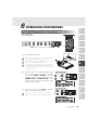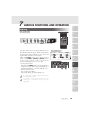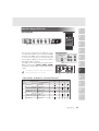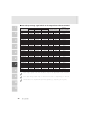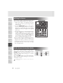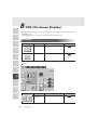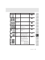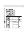
1
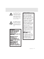
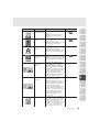
VISUAL PRESENTER
HV-7100SX
INSTRUCTION MANUAL
Please read this instruction manual carefully before using this product and keep it for future reference.
IMPORTANT SAFEGUARDS
■ Read Instructions – All the safety
and operating instructions should be
read before the appliance is
operated.
■ Retain Instructions – The safety and
operating instructions should be
retained for future reference.
■ Heed Warnings – All warnings on
the product and in the operating
instructions should be adhered to.
■ Follow Instructions – All operating
and use instructions should be
followed.
■ Cleaning – Unplug this product
from the wall outlet before cleaning.
Do not use liquid cleaners or aerosol
cleaners. Use a damp cloth for
cleaning.
■ Attachments – Do not use
attachments not recommended by the
product manufacturer as they may
cause hazards.
■ Water and Moisture – Do not use
this product near water - for example,
near a bath tub, wash bowl, kitchen
sink, or laundry tub, in a wet
basement, or near a swimming pool,
and the like.
■ Accessories – Do not place this
product on an unstable cart, stand,
tripod, bracket, or table. The product
may fall, causing serious injury to a
child or adult, and serious damage to
the product. Use only with a cart,
stand, tripod, bracket, or table
recommended by the manufacturer, or
sold with the product. Any mounting
of the product should follow the
1
manufacturer's instructions, and
should use a mounting accessory
recommended by the manufacturer.
■ Ventilation – Slots and openings in
the cabinet are provided for
ventilation and to ensure reliable
operation of the product and to
protect it from overheating, and these
openings must not be blocked or
covered. The openings should never
be blocked by placing the product on
a bed, sofa, rug, or other similar
surface. This product should not be
placed in a built-in installation such as
a bookcase or rack unless proper
ventilation is provided or the
manufacturer's instructions have been
adhered to.
■ Power Sources – This product
should be operated only from the type
of power source indicated on the
marking label. If you are not sure of
the type of power supply to your
home consult your appliance dealer
or local power company. For products
intended to operate from battery
power, or other sources, refer to the
operating instructions.
■ Grounding or Polarization – This
product may be equipped with either
a polarized 2-wire AC line plug (a
plug having one blade wider than the
other) or a 3-wire grounding type
plug, a plug having a third
(grounding) pin. The 2-wire polarized
plug will fit into the power outlet only
one way. This is a safety feature. If
you are unable to insert the plug fully
into the outlet, try reversing the plug.
If the plug still fails to fit, contact your
electrician to replace your obsolete
outlet. Do not defeat the safety
purpose of the polarized plug. The 3wire grounding type plug will fit into
a grounding type power outlet. This is
a safety feature. If you are unable to
insert the plug into the outlet, contact
your electrician to replace your
obsolete outlet. Do not defeat the
safety purpose of the grounding type
plug.
■ Power-Cord Protection – Powersupply cords should be routed so that
they are not likely to be walked on or
pinched by items placed upon or
against them, paying particular
attention to cords at plugs,
convenience receptacles, and the
point where they exit from the
product.
■ Lightning – For added protection
for this product during a lightning
storm, or when it is left unattended
and unused for long periods of time,
unplug it from the wall outlet and
disconnect the antenna or cable
system. This will prevent damage to
the product due to lightning and
power-line surges.
■ Overloading – Do not overload
wall outlets, extension cords, or
integral convenience receptacles as
this can result in a risk of fire or
electric shock.
■ A product and
cart combination
should be moved
with care. Quick
stops, excessive
force, and uneven
surfaces may cause the product and
cart combination to overturn.
■ Object and Liquid Entry – Never
push objects of any kind into this
product through openings as they
may touch dangerous voltage points
or short-out parts that could result in a
fire or electric shock. Never spill
liquid of any kind on the product.
■ Servicing – Do not attempt to
service this product yourself as
opening or removing covers may
expose you to dangerous voltage or
other hazards. Refer all servicing to
qualified service personnel.
WARNING : Handling the
cord on this product or
cords associated with
accessories sold with this
product, will expose you to
lead, a chemical known to
the State of California to
cause birth defects or
other reproductive harm.
Wash hands after
handling.
2
■ Damage Requiring Service –
Unplug this product from the wall
outlet and refer servicing to qualified
service personnel under the following
conditions:
● When the power-supply cord or
plug is damaged.
● If liquid has been spilled, or
objects have fallen into the
product.
● If the product has been exposed
to rain or water.
● If the product does not operate
normally by following the
operating instructions. Adjust
only those controls that are
covered by the operating
instructions as an improper
adjustment of other controls
may result in damage and will
often require extensive work by
a qualified technician to restore
the product to its normal
operation.
● If the product has been dropped
or damaged in any way.
● When the product exhibits a
distinct change in performance this indicates a need for service.
■ Replacement Parts – When
replacement parts are required, be
sure the service technician has used
replacement parts specified by the
manufacturer or have the same
characteristics as the original part.
Unauthorized substitutions may result
in fire, electric shock or other
hazards.
3
■ Safety Check – Upon completion of
any service or repairs to this product,
ask the service technician to perform
safety checks to determine that the
product is in proper operating
condition.
■ Heat – The product should be
situated away from heat sources such
as radiators, heat registers, stoves, or
other products (including amplifiers)
that produce heat.
CAUTION
RISK OF
ELECTRIC SHOCK
DO NOT OPEN
CAUTION:
TO REDUCE THE RISK OF
ELECTRIC SHOCK, DO NOT
REMOVE COVER (OR BACK).
NO USER-SERVICEABLE
PARTS INSIDE.
REFER SERVICING TO
QUALIFIED SERVICE
PERSONNEL.
SA 1965
SA 1966
The lightning flash with
arrowhead symbol, within an
equilateral triangle, is intended
to alert the user to the presence
of uninsulated "dangerous
voltage" within the product's
enclosure that may be of
sufficient magnitude to constitute
a risk of electric shock to
persons. This marking is located
at the bottom of product.
The exclamation point within
an equilateral triangle is
intended to alert the user to
the presence of important
operating and maintenance
(servicing) instructions in the
literature accompanying the
product.
WARNING:
TO REDUCE THE RISK
OF FIRE OR ELECTRIC
SHOCK, DO NOT
EXPOSE THIS
PRODUCT TO RAIN OR
MOISTURE.
THIS IS A CLASS A
PRODUCT.
IN A DOMESTIC
ENVIRONMENT THIS
PRODUCT MAY CAUSE
RADIO
INTERFERENCE IN
WHICH CASE THE
USER MAY BE
REQUIRED TO TAKE
ADEQUATE MEASURES.
INFORMATION
This equipment has been tested
and found to comply with the
limits for a Class A digital
device, pursuant to Part 15 of
the FCC Rules. These limits are
designed to provide reasonable
protection against harmful
interference when the equipment
is operated in a commercial
environment. This equipment
generates, uses, and can
radiate radio frequency energy
and, if not installed and used in
accordance with the instruction
manual, may cause harmful
interference to radio
communications. Operation of
this equipment in a residential
area is likely to cause harmful
interference in which case the
user will be required to correct
the interference at his own
expense.
USER-INSTALLER
CAUTION:
Your authority to operate this
FCC verified equipment could
be voided if you make changes
or modifications not expressly
approved by the party
responsible for compliance to
Part 15 of the FCC rules.
4
BEFORE YOU USE
■ Use this product under the rated electrical conditions.
■ Do not leave this product under direct sunlight or by heaters, or this
product may be discolored, deformed, or damaged.
■ Do not place this product in any humid, dusty, windy or vibrating
location. Use this product in the following environmental conditions:
Temperature:
5°C~40°C (41°F~104°F)
Humidity:
30%~85% (No condensation)
■ Use a soft, dry cloth for cleaning. Do not use any volatile solvent, such
as thinner or benzine.
■ Do not directly point the camera lens into the sun, or the camera may be
damaged.
■ Caring for the batteries:
• If this product is not used for a long time, take out the batteries from
the wireless remote control.
• Do not use rechargeable Ni-Cd batteries.
• Do not use new and old batteries, or batteries of different types
together.
• Do not try to recharge or short-circuit the batteries.
■ Luminescent and Black Spots
There may be some pixels that do not operate properly due to the use of
CCD Area Image Sensors that are made-up of many pixels. You may
experience luminescent or black spots on the screen; however, this is a
phenomenon of CCD Area Image Sensors and is not malfunction.
5
CONTENTS
1. PART NAMES AND FUNCTIONS
Appearance .......................................................8
Front Operation Panel ...........................................9
Rear Panel .......................................................10
Wireless Remote Control .....................................11
1. PART NAMES
AND FUNCTIONS
1
2. WIRELESS REMOTE
CONTROL
2
3. MOUSE
3
4. SETTING UP AND
CONNECTION
4
5. STORING
5
6. OPERATION
PROCEDURES
6
7. VARIOUS FUNCTION
AND OPERATIONS
7
8. OSD
8
9. RS-232C
SPECIFICATIONS
9
10. TROUBLESHOOTING
HINTS
10
11. SPECIFICATIONS
11
2. WIRELESS REMOTE CONTROL
Receivable Range ..............................................13
Preparation ......................................................13
3. MOUSE
Mouse Operation ..............................................14
4. SETTING UP AND CONNECTION
Setting Up........................................................15
Connection to Monitor and Projector ......................15
Connection to the analog RGB-out terminal .....................16
Connection to the composite video-out terminal ................16
Connection to the S video-out terminal ...........................16
Analog RGB Signal ............................................16
Signal allocation ......................................................16
Pin assignment .........................................................16
5. STORING
Storing ............................................................17
6. OPERATION PROCEDURES
Simple Steps for Presenting Printed Material .............18
Steps for Showing Transparent Material ..................19
7. VARIOUS FUNCTIONS AND OPERATION
Lighting ...........................................................20
Zoom ..............................................................21
Monitor Output selection .....................................22
External input image signal which can be output from
video-out terminal .....................................................23
Electronic Enlargement ........................................24
Color / B&W Selection ......................................25
Posi / Nega Conversion .....................................25
Image Rotation ..................................................26
Pause..............................................................26
Contrast ..........................................................27
White Balance ..................................................28
Iris .................................................................29
Auto iris adjustment ...................................................29
Manual iris adjustment ...............................................30
Focus ..............................................................31
Auto Focus ..............................................................31
Powered Manual Focus ..............................................32
6
1
1. PART NAMES
AND FUNCTIONS
2
2. WIRELESS REMOTE
CONTROL
3
3. MOUSE
CONTENTS
Preset Operation ...............................................33
Image Memory ..................................................34
Splitting the Screen ............................................35
F.A.M. (Frame Accumulate Mode)..........................35
Installation of LCD Monitor ...................................36
Connecting to the LCD Monitor .............................36
"Utility Software CD-ROM" ...................................36
8. OSD (On-Screen Display)
OSD Menu.......................................................37
4. SETTING UP AND
CONNECTION
4
9. RS-232C SPECIFICATIONS
Setting Up........................................................46
Cable Connection..............................................46
Data Format Specifications...................................47
Transmission Command (PC → Visual Presenter) ...............47
Response data format (Visual Presenter → PC) .................47
5
5. STORING
6
6. OPERATION
PROCEDURES
10. TROUBLESHOOTING HINTS
7
7. VARIOUS FUNCTION
AND OPERATIONS
11. SPECIFICATIONS
8
8. OSD
9
9. RS-232C
SPECIFICATIONS
10
10. TROUBLESHOOTING
HINTS
11
11. SPECIFICATIONS
7
Transmission Specifications ..................................48
UART Communication Format ................................49
Connection ......................................................50
Symptoms and Confirmation .................................51
Replacement of Fluorescent Lamp ...........................51
General..................................................................52
Main Camera ..........................................................53
Lighting ..................................................................53
Supplied Accessories .................................................54
Options ..................................................................54
1
PART NAMES AND FUNCTIONS
1
Appearance
2
3
Camera Head
Lamp Arm
Upper Lamp
Lighting Unit
Lighting Unit Arm
4
Infrared Sensor
Column
5
Scroll Mouse
Infrared Emitting
Part
Column Lock
Button
Press this button to
raise/fold the column.
6
Wireless Remote
Control
Stage
Base Lamp
7
Pocket for Wireless
Remote Control
8
Front Operation Panel
Microphone Jack
9
10
11
8
Front Operation Panel
1
2 Iris
1 Pause
3 White
Balance
2
MONITOR OUTPUT
RGB1
PAUSE
RGB2
F.A.M.
OPEN
IRIS
CLOSE
AUTO/MANUAL
WHITE
BALANCE
TELE
CONTRAST
WIDE
MAIN
3
IMAGE ROTATION POSI / NEGA
LAMP
AF
ZOOM
UPPER / BASE / OFF
4
4 Monitor Output
5 F.A.M.
6 Image
7 Posi/Nega
Rotation
Selection
Conversion
8 Lamp 9 Contrast 10 Zoom
11 Auto
Focus
5
Name
6
7
8
9
10
11
9
Function
Reference Page
1
Pause
To change the setting between still image
and video.
P.26
2
Iris
To adjust the brightness of the screen.
P.29
3
White Balance
To change the mode between AUTO
and ONE-PUSH.
P.28
4
Monitor Output Selection To change the output line.
P.22
5
F.A.M.
To select F.A.M.
(Frame Accumulate Mode)
P.35
6
Image Rotation
To rotate the image. Every time this button
is pressed, the image rotates
counterclockwise by 90°.
7
Posi/Nega Conversion
To switch Posi/Nega.
8
Lamp
To switch the lighting.
P.26
P.25
P.19
P.20
9
Contrast
To make documents, etc. visible clearly.
P.27
10
Zoom
To zoom the object.
P.21
11
Auto Focus
To focus automatically.
P.31
Rear Panel
1
6 Analog RGB-in
4 Stereo 5 Analog RGB-out
1 Power Cord 2 12VDC Out 3 RS-232C
Audio
Terminal
Terminal
Terminal 1
Terminal
Receptacle
.
Output
[RS-232C]
[DC12V]
[AC IN]
[OUTPUT RGB OUT] [INPUT.RGB1]
Terminal
2
3
7 Mouse
8 USB
9 Vide-out Terminal
10 Analog RGB-in 11
Terminal
Terminal
[OUTPUT.S-VIDEO
Terminal 2
[MOUSE]
[USB]
/VIDEO]
[INPUT.RGB2]
S-Video (mini DIN 4P),
Composite video (RCA pinjack)
Name
Function
1
Power Cord Receptacle [AC IN] Connected to the power cord connector.
2
12VDC Out Terminal
[DC12V]
To output DC12V and the image. This
connecting terminal specially designed
for the LCD monitor (LM-5011N)
available separately.
4
Stereo 12 DIP
Audio
Switch
Input
Terminal
1/2
5
Reference Page
6
P.36
Do not connect the equipment other
than LM-5011N.
7
3
RS-232C Terminal
[RS-232C]
To connect the RS-232C cable when
controlling the main unit from the PC.
P.46
4
Stereo Audio Output
Terminal
To output sound to audio input equipment.
P.22
5
Analog RGB-out
Terminal
[OUTPUT.RGB OUT]
Image is output when this terminal is
connected to RGB input equipment
(e.g., LCD projector, multi-sync monitor).
P.16
6
Analog RGB-in
Terminal1
Input image is output through analog
RGB-out terminal and video-out terminal
when the input selection is set at RGB1.
P.22
7
Mouse Terminal [MOUSE] To connect the mouse (supplied accessory).
P.14
8
USB Terminal [USB]
P.36
9
Video-out Terminal
To output images to the NTSC/PAL
[OUTPUT.S-VIDEO/VIDEO] monitor, such as TV monitor.
S-Video (mini DIN 4P)
Composite video
(RCA pinjack)
[INPUT.RGB1]
If connected to PC with the attached USB
cable, it is possible to transfer images
and control the main unit by using the
software in the attached Utility Software
CD-ROM.
8
9
10
11
P.15
P.16
10
Name
1
2
Function
Reference Page
10
Analog RGB-in
Terminal 2
[INPUT.RGB2]
Input image is output through analog
RGB-out terminal and video-out terminal
when the input selection is set at RGB2.
P.22
11
Stereo Audio Input
Terminal 1/2
To output input sound from audio output
terminal when the input selection is set at
RGB1/2.
P.22
12
DIP Switch
The functions can be switched as follows:
P.15
3
◊[A] key: To switch the resolution of the image output
from the RGB output terminal [RGB-OUT].
◊[B] key: To switch the video output system.
◊[C] key: To switch the video output screen size.
◊[D] key: To switch the electronic shutter mode.
0
1
4
[A] key
SXGA
XGA
[B] key
NTSC
PAL
[C] key
Over scan
Under scan
[D] key
60
50
Before switching the DIP switch key, be sure
to turn off the power supply to this product.
5
Wireless Remote Control
6
7
LIVE
PAUSE
8
1 PAUSE
3 ARROWS
MEMORY
4 MEMORY NO.
2x
2 2X
5
6
9
10
9
PRESET.SET
PRESET.CALL
POSI/NEGA
COLOR/B&W
13 MONITOR OUTPUT.
MAIN
16 ZOOM.TELE
17 ZOOM.WIDE
10
21 IRIS.NORMAL
11
22 IRIS.OPEN
11
7 IMAGE.SET
SET
PRESET CALL
SET
IMAGE CALL
POSI/NEGA COLOR/B&W
UPPER
LAMP BASE
MONITOR
OUTPUT
RGB1
RGB2
MAIN
TELE
ZOOM WIDE
NORMAL
OPEN
NEAR FOCUS FAR
CLOSE
8 IMAGE.CALL
11 LAMP.UPPER
12 LAMP.BASE
14 MONITOR OUTPUT.RGB 1
15 MONITOR OUTPUT.RGB 2
18 FOCUS.NEAR
19 FOCUS.FAR
AF
20 AUTO FOCUS
IRIS
23 IRIS.CLOSE
Button Name
Function
To change the setting between still image
and video.
1 PAUSE
Reference Page
2 ELECTRONIC
2X
To double the image size.
3 ENLARGEMENT ARROWS To scroll the screen during magnification
(electronic enlargement) mode. This
button is also used to move the pointer
when it appears.
P.24
4 MEMORY NO.
The memory No. used with 5 to 8 .
When the live image and the image from
the memory are displayed together by
splitting the screen in half, the [1] and [3]
buttons scrolls the live image right and left
and the [4] and [5] buttons scrolls the
image from the memory right and left.
P.35
P.33
5 STATUS
PRESET.SET
To store the operating condition of the
equipment. Used with the memory No.
6
PRESET.CALL
To call the stored operating condition
then. Used with the memory No.
7 IMAGE
IMAGE.SET
To store images in the main unit memory.
Used with the memory No.
8
IMAGE.CALL
[SPLIT]
To call the image stored by [IMAGE.SET]
button. Used with the memory No.
To display the image called out from the
memory together with the live image in
the split screen.
2
3
4
5
P.34
6
P.35
7
9 POSI/NEGA
To switch POSI/NEGA.
P.25
10 COLOR/B&W
To switch COLOR/B&W.
P.25
11 LAMP
UPPER
To turn ON/OFF the upper lamp.
P.20
12
BASE
To turn ON/OFF the base lamp.
13 MONITOR MAIN
OUTPUT
RGB1
1
P.26
8
To change the output line.
P.22
9
P.21
10
14
15
RGB2
16 ZOOM
TELE
To zoom in.
17
WIDE
To zoom out.
18 FOCUS
NEAR
To move the focus near.
19
FAR
To move the focus far.
20
AUTO FOCUS To focus automatically.
21 IRIS
NORMAL
To reset the AUTO iris to the initial value.
22
OPEN
To open the AUTO/MANUAL iris.
23
CLOSE
To close the AUTO/MANUAL iris.
P.32
11
P.31
P.29
12
1
2
WIRELESS REMOTE CONTROL
Receivable Range
Point the infrared emitting part of the wireless remote control at the infrared sensor of this
product, and press the button for desired function. The receivable range may be narrowed
when the Presenter is placed under sunlight, near an inverter fluorescent lamp or in any other
unfavorable surroundings. Depending on the conditions of fluorescent lamps, etc. the sensor
may fail to receive the infrared light. In such a case, relocate this poduct, or take other
countermeasures.
2
3
• Receivable range
Distance : Approx. 7 m (23 ft.) or less from the light receiving area to the front of the
wireless remote control.
Angle
: Approx. 30° degrees or less from the light receiving area to the front of the
wireless remote control rightward, leftward, upward and downward,
respectively.
4
30
30°
5
°
30°
30°
30°
7
30°
6
8
Preparation
9
Remove the battery case cover by pressing downward on the [ OPEN] mark part in the
direction as indicated by the arrow.
Install 2 pcs of batteries (type R03, AAA) into the case in the direction as indicated there.
10
Install the batteries with the polarity.
Change the batteries once a year.
11
The supplied batteries are only for use in initially confirming the operation of this product. It
is not guaranteed that these batteries can work effectively for the indicated period.
13
3
MOUSE
1
Connect the mouse to the mouse terminal [MOUSE] on the rear panel.
Mouse Operation
2
• Click the right button
Mouse
To display or clear the pointer and OSD menu, operate
Right button
the OSD menu, drawing function control, screen scroll
Left button
start and electronic enlargement.
Moves in the following sequence during normal use;
Displaying pointer → Displaying ENTER icon →
Displaying OSD menu → Clearing OSD menu → Clearing
ENTER icon → Clearing pointer. Displaying and clearing
of the ENTER icon does not function when the
Center button
magnification (electronic enlargement), image rotation
Mouse wheel
(90°, 270°), multi-screen display or drawing function are
selected.
The screen scroll is usable during the multi-screen display, electronic enlargement and
image rotation (90°, 270°). (The pointer is shown then with
symbol).
Start
The pointer
is displayed.
Click
Click
The ENTER
icon is
displayed.
The Pointer
is cleared.
Click the
ENTER icon
Click
The OSD
menu is
displayed.
Click the
EXIT icon
The ENTER
icon is
cleared.
3
4
5
The OSD menu is
cleared. (The ENTER
icon is displayed.)
6
7
Click
• Drag with the left button down (click and hold down to move)
To scroll the screen in electronic enlargement, image rotation (90°, 270°) and multi-screen
display
• Roll the mouse wheel
To scroll up/down the screen in electronic enlargement and image rotation (90°, 270°)
function
• Click the right button
To operate display on/off of the zoom window.
It is also used as cancel button when straight line drawing and square shape drawing
functions are selected.
8
9
10
Click the OSD menu, then the menu functions are given priority.
When using the mouse, connect the mouse to the product turning on the power supply to this
product.
Use the attached mouse. If another mouse is used, the normal operation cannot be guaranteed.
11
The OSD display is assumed to be used for large projection sizes with a projector or the like.
Therefore, the display on a hand monitor or a TV may be hard to see.
Reference Page
• Electronic enlargement ... P.24
• OSD ... P.37
14
1
4
SETTING UP AND CONNECTION
Setting Up
(1)
2
Unfold the lamp arms fully until they come to the
dead end.
Unfold in the sequence specified in the drawing
shown to the right.
2
1
3
(2)
Press the column lock button, and raise the
column until the column lock button returns to
the original position. Make sure that the column
has been completely locked.
(3)
Turn the camera head until the lens faces to the
stage.
4
5
5
3
4
(4)
6
7
Plug the power cord into the power cord
receptacle of this product and the AC outlet.
Connection to Monitor and Projector
The following settings of this product can be switched with the DIP switch. Switch the settings
according to the connection environment. The factory settings are as shown in the following
table:
8
Initial setting
Key
9
A
B
C
D
10
Function
To switch the resolution of images output from RGB terminals
To switch the VIDEO output system
To switch the screen size of VIDEO output
To switch the electronic shutter mode
Key selection
Content
0
0
0
0
SXGA
NTSC
Over scan
60
In the area where the rated supply frequency is 50Hz, when the D key is used as set at “0,”
fluorescent lamps, mercury lamps and other AC lamps may suffer “flicker” due to the lighting
of their discharge tubes. In this case, set the D key to “1,” and the flicker may be reduced. In
the area where the rated supply frequency is 60Hz, use the D key as factory set at “0.”
11
Be sure to turn off the power supply to all equipment before making any connections to
protect this product and all the connected equipment.
When switching the DIP switch key, be sure to turn off the power supply beforehand.
When plugging/unplugging cables, be sure to do so by holding the plugs.
15
■ Connection to the analog RGB-out terminal
Connect the analog RGB-out terminal [OUTPUT·RGBOUT] to the equipment having an analog
RGB-in terminal with the analog RGB cable (attached) or a connection cable available on the
market.
At this time, the position of the display may be deviated from the center. If deviated, manually
adjust the horizontal and vertical positions on the connected equipment side.
Also, vertical stripes may appear on the screen of the LCD projector. That can be alleviated
by manually adjusting the dot clock frequency on the projector side.
LCD projector
1
2
3
CRT Monitor
or
4
■ Connection to the composite video-out terminal
Connect the composite video output terminal [VIDEO] and the audio output terminal [AUDIO]
(RCA pin) with the video/audio cable with RCA pin plug as attached or available on market.
5
TV Monitor
6
■ Connection to the S video-out terminal
Use the S video terminal [S-VIDEO](mini-DIN4P) and the S-video cable as attached or
available on market.
7
TV Monitor
8
Hold the cable plug when connecting or disconnecting the cables.
Analog RGB Signal
9
■ Signal allocation
5
4
3
2
1
Video signal :
10
9
8
7
6
15 14 13 12 11
Analog 0.7V(p-p) 75Ω terminated
10
Horizontal synchronized signal : TTL level (positive/negative polarity)
Vertical synchronized signal :
TTL level (positive/negative polarity)
DSUB 15P shrink terminal (Female)
11
■ Pin assignment
Pin No.
1
2
3
4
5
Name
Video signal (Red)
Video signal (Green)
Video signal (Blue)
N.C
GND
Pin No.
6
7
8
9
10
Name
GND (Red)
GND (Green)
GND (Blue)
N.C
GND
Pin No.
Name
11
12
13
14
15
GND
N.C
Horizontal synchronized signal
Vertical synchronized signal
N.C
16
1
5
STORING
Storing
When the LCD monitor is mounted, this product cannot
be stored.
Remove the LCD monitor, and then store this product.
2
(1)
Turn off the power switch, and unplug the
power cord and the video cable.
(2)
Turn the camera head so that it may be ready to
be stored.
3
4
1
The illustration shows the right storage position of
the camera head. Never apply excessive force to
the column.
5
(3)
Press the column lock release button, and fold
down the main column.
2
3
The illustration shows the right storage position of
the column. Never apply excessive force to the
column.
6
(4)
7
Fold down the lighting unit arms 4 and 5 .
Be sure to fold down arm 4 first as per the
illustration.
4
8
5
9
10
11
17
6
OPERATION PROCEDURES
1
Simple steps for Presenting Printed Material
Front operation panel
Wireless remote control
2
LIVE
PAUSE
MEMORY
MONITOR OUTPUT
RGB1
PAUSE
RGB2
F.A.M.
OPEN
IRIS CLOSE
AUTO/MANUAL
WHITE
BALANCE
TELE
CONTRAST
WIDE
2x
SET
MAIN
IMAGE ROTATION POSI / NEGA
LAMP
PRESET CALL
3
IMAGE CALL
POSI/NEGA COLOR/B&W
UPPER
LAMP BASE
MONITOR
OUTPUT
RGB1
RGB2
MAIN
UPPER / BASE / OFF
(2)
(2)
SET
AF
ZOOM
(3)
TELE
ZOOM WIDE
NORMAL
OPEN
NEAR FOCUS FAR
CLOSE
AF
IRIS
(3)
4
(1)
Turn on the power switch.
5
Before turning on the power switch, connection to
the monitor should have been completed.
The indicator lamp (green LED) on the front panel
shows the initial status of each function.
6
If the power switch is turned on immediately after
being turned off, this product may not operate. For
restarting, turn off this product and wait several
seconds then turn on.
(2)
Place the object on the stage. Adjust the image
size according to the object size by using the
zoom buttons ([TELE] / [WIDE]) on the front
operation panel or the zoom tele/wide buttons
([ZOOM . TELE] / [ZOOM . WIDE]) on the
wireless remote control, while watching the
image on the TV monitor.
7
Front operation panel
WHITE
BALANCE
MANUAL
MP
Press the auto focus button [AF] on the front
panel or the wireless remote control.
The auto focus function works up to a height of
approx. 10cm (3.9 in) above the stage surface.
ZOOM
CONTRAST
A
WIDE
8
Wireless remote control
TELE
ZOOM WIDE
NORMAL
(3)
TELE
OPEN
9
NEAR FOCUS FAR
CLOSE
AF
10
Front operation panel
CONTRAST
ZOOM
AF
WIDE
11
Wireless remote control
NORMAL
OPEN
CLOSE
AF
IRIS
18
Steps for Showing Transparent Material
1
Front operation panel
Wireless remote control
2
LIVE
PAUSE
MEMORY
MONITOR OUTPUT
RGB1
PAUSE
RGB2
F.A.M.
OPEN
IRIS CLOSE
AUTO/MANUAL
WHITE
BALANCE
TELE
CONTRAST
WIDE
2x
SET
MAIN
IMAGE ROTATION POSI / NEGA
LAMP
ZOOM
PRESET CALL
IMAGE CALL
POSI/NEGA COLOR/B&W
UPPER
LAMP BASE
MONITOR
OUTPUT
RGB1
RGB2
MAIN
UPPER / BASE / OFF
3
SET
AF
TELE
ZOOM WIDE
NORMAL
(1)
NEAR FOCUS FAR
OPEN
CLOSE
AF
(1)
(2)
IRIS
(2)
4
(1)
5
Press the [LAMP] button on the front panel or
the [LAMP . BASE] button on the wireless
remote control to light up the base light (the
lighting for the transparent documents) built in
the stage.
Front operation panel
IRIS CLOSE
AUTO/MANUAL
TION POSI / NEGA
LAMP
SET
CALL
POSI/NEGA COLOR/B&W
(2)
7
8
9
10
11
19
To turn off the base light, press the
[LAMP.BASE] button on the front panel or on
the wireless remote control again.
CONTRAST
UPPER / BASE / OFF
Wireless remote control
6
WHITE
BALANCE
SET
UPPER
CALL
LAMP BASE
7
VARIOUS FUNCTIONS AND OPERATION
1
Lighting
Wireless remote control
Front operation panel
2
LIVE
PAUSE
MEMORY
MONITOR OUTPUT
RGB1
PAUSE
RGB2
F.A.M.
OPEN
IRIS CLOSE
AUTO/MANUAL
WHITE
BALANCE
TELE
CONTRAST
WIDE
2x
SET
MAIN
IMAGE ROTATION POSI / NEGA
LAMP
ZOOM
PRESET CALL
SET
3
IMAGE CALL
AF
POSI/NEGA COLOR/B&W
UPPER
LAMP BASE
MONITOR
OUTPUT
RGB1
RGB2
MAIN
UPPER / BASE / OFF
TELE
ZOOM WIDE
NORMAL
NEAR FOCUS FAR
OPEN
CLOSE
AF
IRIS
4
The upper lamp unit for presenting material such as
printed matter and 3-D objects, and the base lamp for
presenting transparent material, such as slide, and
negative films, are built in to this product.
When the [LAMP] button on the front operation
panel or the [LAMP] ( [UPPER] / [BASE] ) button
on the wireless remote control is pressed, the
fluorescent lamp lights up in 1 to 3 seconds.
• Front operation panel
Every time the [LAMP] button is pressed, lighting is
switched in a cycle of the upper lamp lights up →
the base lamp lights up → the base lamp goes out.
• Wireless remote control
Turn on/off by each button.
In the initial settings, the upper lighting is on.
Front operation panel
IRIS CLOSE
ON POSI / NEGA
5
WHITE
BALANCE
AUTO/MANUAL
LAMP
CONTRAST
6
UPPER / BASE / OFF
Wireless remote control
SET
PRESET CALL
POSI/NEGA COLOR/B&W
SET
IMAGE CALL
UPPER
7
LAMP BASE
8
It is impossible to have the upper lamp and the
base lamp lit up together.
9
To obtain a sharp image with good color
rendering, it is sometimes necessary to use the
upper lamp.
10
11
20
Zoom
1
Front operation panel
Wireless remote control
2
LIVE
PAUSE
MEMORY
MONITOR OUTPUT
RGB1
PAUSE
RGB2
F.A.M.
OPEN
IRIS CLOSE
AUTO/MANUAL
WHITE
BALANCE
TELE
CONTRAST
WIDE
2x
SET
MAIN
IMAGE ROTATION POSI / NEGA
LAMP
ZOOM
PRESET CALL
IMAGE CALL
POSI/NEGA COLOR/B&W
UPPER
LAMP BASE
MONITOR
OUTPUT
RGB1
RGB2
MAIN
UPPER / BASE / OFF
3
SET
AF
TELE
ZOOM WIDE
NORMAL
OPEN
NEAR FOCUS FAR
CLOSE
AF
IRIS
4
Press the [TELE] button on the front operation panel
or the [ZOOM.TELE] button on the wireless remote
control, and the image will gradually be enlarged.
When the optical zoom reaches the maximum TELE
side (about 10 times), a message of “PRESS TELE FOR
DIGITAL ZOOM” appears on the screen. When the
same button is pressed again, the electronic zoom
function is activated, and the image can be further
magnified up to 2 times (up to about 20 times when
used with the optical zoom function).
5
6
Front operation panel
WHITE
BALANCE
TELE
CONTRAST
WIDE
Wireless remote control
MONITOR
OUTPUT
MAIN
TELE
7
ZOOM WIDE
RGB1
Press the [WIDE] button on the front operation panel
or the [ZOOM.WIDE] button on the wireless remote
control, and the image will gradually be reduced.
RGB2
NEAR FOCUS FAR
When the image is zoomed electronically, the
quality of the image degrades due to pixelation.
8
AF
ZOOM
AF
Front operation panel
WHITE
BALANCE
TELE
CONTRAST
WIDE
AF
ZOOM
9
Wireless remote control
10
MAIN
TELE
MONITOR
OUTPUT
ZOOM WIDE
RGB1
RGB2
NEAR FOCUS FAR
AF
11
Also, by continuously pressing the zoom button, the
zooming speed becomes faster. (Double speed
function)
21
Monitor Output Selection
1
Wireless remote control
Front operation panel
2
LIVE
PAUSE
MEMORY
MONITOR OUTPUT
RGB1
PAUSE
RGB2
F.A.M.
OPEN
IRIS CLOSE
AUTO/MANUAL
WHITE
BALANCE
TELE
CONTRAST
WIDE
2x
SET
MAIN
IMAGE ROTATION POSI / NEGA
LAMP
ZOOM
PRESET CALL
SET
IMAGE CALL
AF
POSI/NEGA COLOR/B&W
UPPER
LAMP BASE
MONITOR
OUTPUT
RGB1
RGB2
MAIN
UPPER / BASE / OFF
TELE
ZOOM WIDE
NORMAL
3
NEAR FOCUS FAR
OPEN
CLOSE
AF
IRIS
4
The respective images from two different sources
connected to this product such as a PC and an ELMO
Presenter "HV-110XG" can be alternately presented
on a TV by selecting the source by pressing the
desired Monitor Output selection buttons without
changing the cable connections.
The image can be switched by pressing the Monitor
Output selection button [RGB1], [RGB2], [MAIN]
on the front operation panel or on the wireless remote
control.
Front operation panel
MONITOR OUTPUT
RGB1
PAUSE
RGB2
F.A.M.
5
MAIN
6
Wireless remote control
POSI/NEGA COLOR/B&W
UPPER
LAMP BASE
MONITOR
OUTPUT
RGB1
RGB2
MAIN
The lighting of indicator lamp on the front panel
indicates which input is now selected.
7
8
• Table of Video- and Audio-in / out Terminal Selections
Output signal
Input
Main
Unit
Video-out Terminal
RGB
Audio-out Terminal
L
R
9
Main camera video signal
Microphone
Monaural
Main camera video signal
RGB1
External video signal 1
RGB1
External audio signal 1
Stereo 1 (L/R)
Microphone
Monaural
10
Main camera video signal
RGB2
External video signal 2
RGB2
External audio signal 2
Stereo 2 (L/R)
Microphone
Monaural
11
22
■ External input image signal which can be output from video-out terminal
1
Signal
Mode name
VGA1
VGA2
VGA3
VGA@60Hz
VGA@72Hz
VGA@75Hz
VGA@85Hz
SVGA@56Hz
SVGA@60Hz
SVGA@72Hz
SVGA@75Hz
SVGA@85Hz
XGA@60Hz
XGA@70Hz
XGA@75Hz
XGA@85Hz
SXGA1
SXGA2
SXGA3
SXGA@60Hz
SXGA@75Hz
SXGA@85Hz
UXGA@60Hz
UXGA@65Hz
UXGA@70Hz
UXGA@75Hz
UXGA@85Hz
Mac 13
Mac 16
Mac 19
Mac 21
PC98
2
3
4
5
6
7
8
Frequency
Horizontal
Vertical
Pixel clock
kHz
37.861
37.861
37.927
31.469
37.861
37.500
43.269
35.156
37.879
48.077
46.875
53.674
48.363
56.476
60.023
68.677
67.500
60.000
85.938
63.981
79.976
91.146
75.000
81.250
87.500
93.750
106.250
35.000
49.725
60.241
68.681
24.825
Hz
84.889
85.080
85.039
59.941
72.809
75.000
85.008
56.250
60.317
72.188
75.000
85.061
60.004
70.069
75.029
84.997
75.000
60.000
85.003
60.020
75.025
85.024
60.000
65.000
70.000
75.000
85.000
66.667
74.550
74.927
75.062
56.420
MHz
31.500
31.500
35.500
25.175
31.500
31.500
36.000
36.000
40.000
50.000
49.500
56.250
65.000
75.000
78.750
94.500
108.000
108.000
148.500
108.000
135.000
157.500
162.000
175.500
189.000
202.500
229.500
30.240
57.283
80.000
100.000
21.052
Resolution
(Number of lines)
Horizontal
640
640
720
640
640
640
640
800
800
800
800
800
1024
1024
1024
1024
1152
1280
1280
1280
1280
1280
1600
1600
1600
1600
1600
640
832
1024
1152
640
Vertical
350
400
400
480
480
480
480
600
600
600
600
600
768
768
768
768
864
960
960
1024
1024
1024
1200
1200
1200
1200
1200
480
624
768
870
400
Polarity of
the synchronized signal
(P: Positive, N: Negative)
HS/VS
P/N
N/P
N/P
N/N
N/N
N/N
N/N
P/P
P/P
P/P
P/P
P/P
N/N
N/N
P/P
P/P
P/P
P/P
P/P
P/P
P/P
P/P
P/P
P/P
P/P
P/P
P/P
N/N
N/N
N/N
N/N
N/N
Input image signals other than the above may not be applicable to this Presenter.
9
Some input image signals may not allow the Presenter to output images in full size.
This Presenter is not complied with synchronous signals (e.g., composite, sync on green)
10
11
23
Electronic Enlargement
When the [2×] button on the wireless remote control
is pressed, the image is enlarged double on the
central part. When the pointer is on display and the
right button of the mouse is clicked, the target area to
be magnified double is highlighted. (Zoom window)
When the target area to be enlarged is moved by
dragging the mouse and then the left button of the
mouse is clicked, the highlighted target area is
enlarged. The enlarged image can be scrolled by
using the arrow buttons on the wireless remote control
or by manipulating the mouse.
•The mouse can be operated
as follows:
• Left button........ To scroll the image
according to the
dragging of the mouse while
holding down the left button.
• Mouse wheel ... To scroll up/down the enlarged
screen.
• Right button ..... To turn on/off the double
enlargement. When any image is
enlarged electronically, the
pointer becomes the mark
.
1
Wireless remote control
2
LIVE
PAUSE
MEMORY
2x
SET
PRESET CALL
SET
POSI/NEGA COLOR/B&W
UPPER
LAMP BASE
MONITOR
OUTPUT
RGB1
RGB2
MAIN
TELE
ZOOM WIDE
NORMAL
OPEN
3
IMAGE CALL
4
NEAR FOCUS FAR
CLOSE
AF
5
IRIS
Reference Page
6
•Mouse..... P.14
•OSD........ P.37
7
When the electronic enlargement is operated while
the pointer or the OSD menu is displayed, the
pointer or the ENTER icon cannot be turned
on/off, since the left button of the mouse is
dedicated for scroll function.
To turn on/off the pointer or the ENTER icon, the
electronic enlargement function must be in off
state.
8
9
The images from the memory cannot be enlarged
electronically, and the electronically enlarged
images cannot be stored in the memory.
10
11
24
Color / B&W Selection
1
Wireless remote control
To present the B&W (Black&White) material such as
documents. A clearer image can be achieved without
color blur on a monitor.
If the [COLOR/B&W] button on the wireless remote
control is pressed, images are switched.
2
LIVE
PAUSE
MEMORY
2x
SET
3
PRESET CALL
POSI/NEGA COLOR/B&W
UPPER
LAMP BASE
MONITOR
OUTPUT
RGB1
RGB2
MAIN
4
IMAGE CALL
SET
TELE
ZOOM WIDE
NORMAL
NEAR FOCUS FAR
OPEN
AF
CLOSE
IRIS
5
Posi / Nega Conversion
6
Wireless remote control
Front operation panel
7
LIVE
PAUSE
MEMORY
MONITOR OUTPUT
RGB1
PAUSE
RGB2
F.A.M.
OPEN
IRIS CLOSE
AUTO/MANUAL
WHITE
BALANCE
TELE
CONTRAST
WIDE
2x
SET
MAIN
IMAGE ROTATION POSI / NEGA
LAMP
ZOOM
PRESET CALL
SET
IMAGE CALL
AF
POSI/NEGA COLOR/B&W
MONITOR
OUTPUT
MAIN
UPPER / BASE / OFF
TELE
8
ZOOM WIDE
NORMAL
OPEN
UPPER
LAMP BASE
RGB1
RGB2
NEAR FOCUS FAR
CLOSE
AF
IRIS
To show a negative film.
Press the [POSI / NEGA] button on the front
operation panel or wireless remote control, the
indicator lamp lights up and the image will be
converted to the NEGA mode accordingly.
When the [POSI / NEGA] button is pressed again,
the indicator lamp goes out and the POSI mode is
resumed.
9
10
In the condition of NEGA, the followings are
restricted.
• When contrast on: Gamma adjustment is not
available.
• Only When Gamma setting γ = 07: Contrast can
be turned on.
11
NEGA setting at the factory
• Gamma: γ = 07 (0.3)
• Contrast: on
• White Balance: Auto mode
25
Front operation panel
OPEN
IRIS CLOSE
AUTO/MANUAL
IMAGE ROTATION POSI / NEGA
LAMP
UPPER / BASE / OFF
Wireless remote control
SET
PRESET CALL
POSI/NEGA COLOR/B&W
SET
IMAGE CALL
UPPER
LAMP BASE
W
B
CO
Image Rotation
1
Front operation panel
MONITOR OUTPUT
RGB1
PAUSE
RGB2
F.A.M.
OPEN
IRIS CLOSE
AUTO/MANUAL
WHITE
BALANCE
TELE
CONTRAST
WIDE
MAIN
IMAGE ROTATION POSI / NEGA
LAMP
ZOOM
AF
2
UPPER / BASE / OFF
When the [IMAGE ROTATION] button on the front
operation panel is pressed, the image rotates. Every
time the [IMAGE ROTATION] button is pressed, the
image rotates counterclockwise by 90°.
When the image is rotated, indicator lamp goes on.
Front operation panel
PAUSE
OPEN
3
IRIS CLOSE
IMAGE ROTATION POSI / NEGA
F.A.M.
4
When the image rotation (90°, 270°) is operated
while the pointer or the OSD menu is displayed,
the pointer or the ENTER icon cannot be turned on/off, since the left button of the mouse is
dedicated for scroll function. To turn on/off the pointer or the ENTER icon, the image rotation
(90°, 270°) function must be cancelled.
5
The image does not rotate when Pause mode is working.
The images from the memory cannot be rotated.
6
Pause
Wireless remote control
Front operation panel
7
LIVE
PAUSE
MEMORY
MONITOR OUTPUT
RGB1
PAUSE
RGB2
F.A.M.
OPEN
IRIS CLOSE
AUTO/MANUAL
WHITE
BALANCE
TELE
CONTRAST
WIDE
SET
MAIN
IMAGE ROTATION POSI / NEGA
LAMP
8
2x
ZOOM
PRESET CALL
SET
IMAGE CALL
AF
POSI/NEGA COLOR/B&W
UPPER
LAMP BASE
MONITOR
OUTPUT
RGB1
RGB2
MAIN
UPPER / BASE / OFF
TELE
ZOOM WIDE
NORMAL
NEAR FOCUS FAR
OPEN
CLOSE
AF
IRIS
When the [PAUSE] button on the front operation
panel is pressed, the image from the main camera
pause.
When the [PAUSE] button is pressed again, the
pause mode is canceled.
9
Front operation panel
RGB1
PAUSE
RGB2
F.A.M.
OPEN
10
IRIS CLOSE
IMAGE ROTATION POSI / NEG
11
Wireless remote control
PAUSE
LIVE
MEMORY
26
Contrast
1
Front operation panel
MONITOR OUTPUT
2
RGB1
PAUSE
RGB2
F.A.M.
OPEN
IRIS CLOSE
AUTO/MANUAL
WHITE
BALANCE
TELE
CONTRAST
WIDE
MAIN
IMAGE ROTATION POSI / NEGA
LAMP
ZOOM
AF
UPPER / BASE / OFF
To present the material with a little half tone such as
documents.
Images with sharp characters and lines contrasty with
background can be obtained.
When the [ C O N T R A S T ] button on the front
operation panel is pressed, the indicator lamp lights
up, and the image becomes contrasty.
When the [CONTRAST] button is pressed again, the
indicator lamp goes out, and the image is reset to the
normal condition.
3
4
5
In the condition of NEGA, contrast is turned on
only when the gamma setting is γ = 07 (0.3).
6
7
8
9
10
11
27
Front operation panel
F
WHITE
BALANCE
TELE
CONTRAST
WIDE
ZOOM
AF
White Balance
1
Front operation panel
MONITOR OUTPUT
RGB1
PAUSE
RGB2
F.A.M.
OPEN
IRIS CLOSE
WHITE
BALANCE
TELE
CONTRAST
WIDE
AUTO/MANUAL
MAIN
IMAGE ROTATION POSI / NEGA
LAMP
ZOOM
2
AF
UPPER / BASE / OFF
The camera of this product automatically adjusts the
shooting color balance (AUTO mode). However,
depending on the color arrangement of document or
the like, this color balance may be lost.
In such case, shoot the stage surface, and press the
[WHITE BALANCE] button on the front operation
panel. Then, the indicator lamp blinks and then lights
up, and the white balance is fixed. (ONE-PUSH
mode)
When the [WHITE BALANCE] button is pressed
again, the indicator lamp goes out, and the mode
returns to the AUTO mode.
3
Front operation panel
WHITE
BALANCE
TELE
CONTRAST
WIDE
ZOOM
AF
4
F
5
6
AUTO .................. To set the white balance in the auto follow mode (initial setting).
ONE-PUSH ........... To set the push-set white balance. By pressing the [WHITE BALANCE]
button, the white balance for the then color temperature is fixed.
7
The automatically followed color temperature ranges from approx. 3000k to 8000k.
8
When the white balance is set to the MANUAL mode on the OSD, the white balance is fixed,
and the indicator lamp remains lighting. When the white balance button [WHITE BALANCE]
on the operation panel is pressed while the indicator lamp is lighting, the indicator lamp goes
out, and the mode is switched to the AUTO mode.
Reference Page
9
• OSD....... P.37
10
11
28
Iris
1
Wireless remote control
Front operation panel
2
LIVE
PAUSE
MEMORY
2x
MONITOR OUTPUT
RGB1
PAUSE
RGB2
F.A.M.
OPEN
IRIS CLOSE
AUTO/MANUAL
WHITE
BALANCE
TELE
CONTRAST
WIDE
SET
MAIN
IMAGE ROTATION POSI / NEGA
LAMP
ZOOM
AF
PRESET CALL
UPPER
LAMP BASE
MONITOR
OUTPUT
RGB1
RGB2
MAIN
UPPER / BASE / OFF
3
IMAGE CALL
SET
POSI/NEGA COLOR/B&W
TELE
ZOOM WIDE
NORMAL
OPEN
NEAR FOCUS FAR
CLOSE
AF
IRIS
4
To adjust the brightness of image by adjusting the lens opening.
• Auto iris ........... Adjusts brightness automatically.
• Manual iris ....... Adjusts brightness manually.
5
■ Auto iris adjustment
To adjust the level of brightness automatically
according to the object.
Press the iris button [OPEN] on the front panel or the
[IRIS.OPEN] button on the wireless remote control to
open the iris.
Press the iris button [CLOSE] on the front panel or the
[IRIS.CLOSE] button on the wireless remote control to
close the iris.
Press the [IRIS . NORMAL] button on the wireless
remote control,to change setting back to the defaults.
Press and hold the auto/manual selection button
[AUTO.MANUAL] on the front operation panel for
more than 4 seconds or press the [IRIS.NORMAL]
button on the wireless remote control to return to the
initial setting.
6
7
8
9
10
11
29
Front operation panel
OPEN
IRIS CLOSE
AUTO/MANUAL
AGE ROTATION POSI / NEGA
LAMP
UPPER / BASE / OFF
Wireless remote control
NORMAL
OPEN
IRIS
NEAR
FAR
CLOSE
AF
WH
BAL
CONT
■ Manual iris adjustment
To lock the image to a certain brightness. Press the
iris button [AUTO/MANUAL] on the front panel,
then the indicator lamp goes on to enable the
adjustment by manual iris.
Press the iris button [OPEN] on the front panel or the
[IRIS.OPEN] button on the wireless remote control,to
open the iris.
Press the iris button [CLOSE] or the [IRIS.CLOSE]
button on the wireless remote control to close iris.
Press the iris button [AUTO/MANUAL] again, and
the indicator lamp goes off, to return to the auto iris.
Front operation panel
OPEN
IRIS CLOSE
AUTO/MANUAL
AGE ROTATION POSI / NEGA
LAMP
WH
BAL
CONT
2
UPPER / BASE / OFF
Wireless remote control
NORMAL
OPEN
NEAR
FAR
CLOSE
AF
1
3
IRIS
The default setting is Auto iris.
4
In time of manual iris, the iris is locked, and does
not follow the brightness change of the object.
5
6
7
8
9
10
11
30
Focus
1
Wireless remote control
Front operation panel
2
LIVE
PAUSE
MEMORY
MONITOR OUTPUT
RGB1
PAUSE
RGB2
F.A.M.
OPEN
IRIS CLOSE
AUTO/MANUAL
WHITE
BALANCE
TELE
CONTRAST
WIDE
2x
SET
MAIN
IMAGE ROTATION POSI / NEGA
LAMP
ZOOM
PRESET CALL
IMAGE CALL
POSI/NEGA COLOR/B&W
UPPER
LAMP BASE
MONITOR
OUTPUT
RGB1
RGB2
MAIN
UPPER / BASE / OFF
3
SET
AF
TELE
ZOOM WIDE
NORMAL
OPEN
NEAR FOCUS FAR
CLOSE
AF
IRIS
4
Adjust the focus of the object.
■ Auto Focus
Press the auto focus button [AF] on the front panel or
the wireless remote control, to activate the auto focus.
While the auto-focus is in operation, the indicator
lamp on the front panel blinks until the object is
brought into focus.
This product features a one-push auto focus function.
Once focusing is completed, the auto focus function is
released, and the focused position maintains
unchanged (FOCUSFREE).
5
6
7
The objects listed below may not be brought into
focus in the auto focus mode. In these cases, use
the manual focus mode.
8
• Objects bearing little contrast
• Objects with fine repeated patterns, such as
lateral stripes and cross stripes
• Objects glittering or reflecting strong light
• Objects with bright background, or excessive
contrast
• The whole image is dark.
• Objects located near and far at the same time
• Objects in motion
9
10
The auto focus function will be canceled if the manual
focus button [FOCUS.NEAR] or [FOCUS.FAR] on
the wireless remote control is pressed.
11
The auto focus function works up to a height of
approx. 10cm (3.9 in) above the stage surface
when the zoom button [TELE] is set to the
maximum.
31
Front operation panel
WHITE
TELE
BALANCE
ZOOM
ONTRAST
AF
WIDE
Wireless remote control
TELE
ZOOM WIDE
NORMAL
OPEN
IRIS
NEAR FOCUS FAR
CLOSE
AF
■ Powered Manual Focus
To focus on specific part of the material, such as 3-D
material.
Press the focus button [FOCUS NEAR] or [FOCUS
FAR] on the wireless remote control.
1
Wireless remote control
LIVE
PAUSE
2
MEMORY
The powered manual focus function works up to a
height of approx. 10cm (3.9 in) above the stage
surface when the zoom button [TELE] is set to the
maximum.
2x
SET
PRESET CALL
SET
IMAGE CALL
POSI/NEGA COLOR/B&W
UPPER
LAMP BASE
MONITOR
OUTPUT
RGB1
RGB2
MAIN
TELE
ZOOM WIDE
NORMAL
OPEN
3
NEAR FOCUS FAR
CLOSE
4
AF
IRIS
5
6
7
8
9
10
11
32
Preset Operation
1
Operation status of this product can be stored / read out
in the memory (max. 8 states can be stored). Operation
states that can be stored are as shown below.
2
• Present zoom angle of view
• The iris state of Auto/Manual selection and its statue.
• White balance status
• On/off of aperture
• Status of gamma
• Lighting status
• Status of color/B&W switch
• Color and shape of the pointer
• Status of image rotation
• On/off of contrast mode
• Status of POSI/NEGA conversion
• Status of F.A.M. selection
• Sound volume
3
4
5
1. How to store
Press the [PRESET.SET] button on the wireless
remote control and press the [MEMORY NO.]
button of the wireless remote control within "4 sec
or less", then the current status of this product is
saved in the pressed number memory.
2. How to read out operation status
Press the [PRSET.CALL] button on the wireless
remote control and press the [MEMORY NO.]
button of the wireless remote control within "4 sec
or less", then this product is set to the memorized
status corresponding to the number.
6
7
8
9
10
11
33
Wireless remote control
LIVE
PAUSE
MEMORY
2x
SET
PRESET CALL
SET
IMAGE CALL
POSI/NEGA COLOR/B&W
UPPER
LAMP BASE
MONITOR
OUTPUT
RGB1
RGB2
MAIN
TELE
ZOOM WIDE
NORMAL
OPEN
NEAR FOCUS FAR
CLOSE
AF
IRIS
The preset (stored) status
is maintained even when
the power is turned off.
Image Memory
Images can be stored in the memory of this Presenter.
(max. 8 sheets)
1. How to store images
Press the [IMAGE.SET] button on the wireless
remote control and press the [MEMORY NO.]
button of the wireless remote control within "4 sec
or less", then the image is stored in the pressed
number.
When the power of the Presenter is turned off, the
images stored in the memory are cleared.
2. How to read out stored images
Press the [IMAGE.CALL] button on the wireless
remote control and press the [MEMORY NO.]
button on the wireless remote control “within
about 4 sec,” then the stored image corresponding to the pressed memory No. is read out.
1
Wireless remote control
2
LIVE
PAUSE
MEMORY
2x
SET
PRESET CALL
SET
IMAGE CALL
POSI/NEGA COLOR/B&W
UPPER
LAMP BASE
MONITOR
OUTPUT
RGB1
RGB2
MAIN
TELE
ZOOM WIDE
NORMAL
OPEN
3
4
NEAR FOCUS FAR
CLOSE
AF
5
IRIS
If the [MAIN] button in the input selection area is
pressed, the camera captured image is displayed
again.
6
7
8
9
10
11
34
Splitting the Screen
1
The live image currently on camera and an image in the
memory can be displayed together on the split screen.
1. Read out the image to be displayed in the split
screen from the memory by the image memory
read-out system.
2. Press the [IMAGE . CALL] button on the wireless
remote control again, and the live image is
displayed on the left half of the screen and the
image from the memory is displayed in the right half
of the screen.
3. The live image can be scrolled right and left with
the [1] and [3] buttons on the wireless remote
control, and the image from the memory can be
scrolled right and left with the [4] and [5] buttons
on the wireless remote control. The images can
also be scrolled by manipulating the mouse.
• How to scroll the images by manipulating the mouse
Bring the mouse either to the live image or the
image from the memory, whichever to be scrolled,
and drag the mouse (move the mouse while
pressing the left button of the mouse), the image
will scroll right and left.
2
3
4
5
6
Wireless remote control
LIVE
PAUSE
MEMORY
2x
SET
PRESET CALL
SET
IMAGE CALL
POSI/NEGA COLOR/B&W
UPPER
LAMP BASE
MONITOR
OUTPUT
RGB1
RGB2
MAIN
TELE
ZOOM WIDE
NORMAL
OPEN
NEAR FOCUS FAR
CLOSE
AF
IRIS
7
F.A.M. (Frame Accumulate Mode)
8
This is used to reduce artifacts in image, and is
appropriate to take pictures of still objects. Press the
[F.A.M.] (Frame Accumulate Mode) button on the
front panel, and the indicator lamp goes on, and the
F.A.M. is selected.
Press the [F.A.M.] (Frame Accumulate Mode) button
again, and the indicator lamp goes off, and the
normal status resumes.
9
10
When the image is rotated, the clear mode does
not function.
11
35
Front operation panel
RGB1
PAUSE
RGB2
F.A.M.
OPEN
IRIS C
IMAGE ROTATION PO
Installation of LCD Monitor
1
To install the LCD monitor (LM-5011N) available
separately, the LCD monitor mounting metal piece
(MS-201) available separately is required.
LCD monitor
LCD
monitor
bracket
2
The LCD monitor (LM-5011N) and the LCD monitor
bracket (MS-201) are available on option, and not
attached to this Presenter (HV-7100SX).
3
4
Connecting to the LCD Monitor
The LCD monitor (LM-5011N) can be connected by
using the LCD monitor out terminal of the Presenter.
When connecting to the LCD monitor out terminal,
confirm the right connection direction.
When using the LCD monitor connection cable, do
not use the AC adapter or video cable attached to
the LCD monitor (LM-5011N).
5
LCD monitor
[LM-5011N]
DC IN 12V
VIDEO IN
6
The LCD monitor (LM-5011N) and the LCD monitor
bracket (MS-201) are available on option, and not
attached to this Presenter (HV-7100SX).
Do not connect any other cable to this terminal.
Negligence will result in the failure of the
equipment.
7
LCD monitor
connection cable
(accessory)
7
9 8
6 5 4 3
2 1
Mini DIN 9P
(Female)
LCD monitor
out terminal [DC 12V]
1
VIDEO OUT
2
GND
3
NC
4
NC
5
NC
6
NC
7
+12V
8
GND
9
CONT.
8
9
10
"Utility Software CD-ROM"
11
The attached "Utility Software CD-ROM" contains the PC link software "Image Mate" and the
TWAIN driver "ELMO TWAIN DS, "and can be operated as shown below.
• To transfer graphic data to PC.
• To operate the Presenter by PC.
For details, see the installation manual for "Utility Software" and "manual.pdf" in the CDROM.
36
1
8
OSD (On-Screen Display)
OSD (On-Screen Display) means the operating menu is displayed on the screen (hereinafter
called OSD menu).
Using this OSD menu, it is possible to operate this product by the mouse.
2
OSD Menu
3
Icon
Name
Function
ENTER
To display the OSD menu.
EXIT
To remove the OSD menu.
Reference Pages
P.14
4
P.14
5
6
● Menu A
7
8
9
10
Icon
11
37
Name
Function
Focus
Near/Far
To adjust the focus .
Reference Pages
P.32
Icon
Name
Function
Auto Focus
To focus the lens automatically.
Zoom
Tele/Wide
To adjust the zoom of the lens.
Reference Pages
1
P.31
2
P.21
3
Iris
Open/Close
To adjust the iris of the lens.
Iris Mode
To switch the Auto/Manual mode.
When this icon is held down for
about 4 sec, the iris is reset to the
initial default value.
P.29
Auto White
Balance
To set the white balance in the
AUTO FOLLOW mode. (initial
setting)
P.28
One-push White
Balance
To set the push-set white
balance. When the left button
of the mouse is clicked, the
white balance for the then
color temperature is fixed.
P.28
Manual White
Balance
To set the white balance with
<RED>, <GREEN> and
<BLUE>. Adjust the white
balance by clicking the left
button of the mouse on the
direction buttons beside the
volume bar.
<RED>…To adjust the red
component (01-99).
<GREEN>…To adjust the green
component (01-99).
<BLUE>…To adjust the blue
component (01-99).
P.28
P.29
4
P.30
5
P.30
6
7
8
9
10
11
38
● Menu B
1
2
3
4
5
Icon
Function
Reference Pages
Upper lamp
on/off
To turn on/off the upper lamp.
When power is turned on, the
previous saved setting remains.
P.20
7
Base lamp
on/off
To turn on/off the base lamp.
When power is turned on, the
previous saved setting remains.
P.19
8
Image rotation
To rotate the image
counterclockwise by 90°.
When power is turned on, the
previous saved setting remains.
P.26
Color/B&W
selection
To switch the selection of the
color/B&W of the screen.
When power is turned on, the
previous saved setting remains.
P.25
POSI/NEGA
conversion
To switch the selection of the
positive/negative of the screen.
When power is turned on, the
previous saved setting remains.
P.25
6
9
Name
10
11
39
P.20
Icon
Name
Function
Contrast Selection To switch the image contrast
setting.
When the power is turned on,
the previous saved setting
remains.
Pause
Aperture
selection
To switch the selection of the
static/moving image.
When power is turned on, the
initial state is Animation.
Volume Adjust
(0 – 63)
Pointer
1
P.27
2
P.26
3
To switch the modulation (edge
emphasis) of the image.
When power is turned on, the
previous saved setting remains.
To switch the image F.A.M.
F.A.M. (Frame
Accumulate Mode) (Frame Accumulate Mode) setting.
When the power is turned on, the
Selection
previous saved setting remains.
Gamma
Adjustment
(0-7)
Reference Pages
4
P.35
5
To switch the gamma setting
value (00(1.0) / 01(0.9) /
02(0.8) / 03(0.7) / 04(0.6) /
05(0.5) / 06(0.4) / 07(0.3)).
When power is turned on, the
previous saved setting remains.
The factory setting is “04
(0.6).” Gamma cannot be
adjusted when the contrast is
on in the negative status.
6
7
8
To adjust the sound volume from
the microphone terminal.
When the power is turned on, the
previous saved setting remains.
Click the left button of the mouse
on the arrow button by the
volume bar and adjust the sound
volume. When the left button of
the mouse is clicked on the sound
volume adjust icon again, the
volume bar disappears. The
factory setting of the sound
volume is 50.
9
10
11
To change the color and shape of
the pointer on the screen. Every
time the left button of the mouse is
clicked, the icon pointer is
switched in order of “White arrow
→ Blue arrow → Yellow arrow →
Red arrow → White line → Blue
line → Yellow line → Red line”.
40
● Menu C
1
2
3
4
5
Icon
Name
Function
Free Line Drawing To draw a free line.
At the beginning of the line, click and hold the left
button (on the mouse), and then move the mouse
pointer by dragging the mouse, and a free line will
be drawn.
6
7
Straight Line
Drawing
8
9
To draw a straight line between two points. Draw a
line by clicking the left button of the mouse on the
starting point, releasing the button, moving the
pointer to the ending point and then clicking the left
button again to complete the line. Then, the straight
line between these 2 points is drawn. To cancel the
first point, click the right button on the mouse before
fixing the second point.
Rectangle Drawing To draw a rectangle.
Click the left button on the mouse on a vertex of a
rectangle to fix the first point. Then, unclick the left
button of the mouse, move the pointer to a vertex of
the opposing corner, and click the left button of the
mouse again to fix the second point. Then, the
rectangle with these 2 points as vertexes is drawn.
To cancel the first point, click the right button of the
mouse before fixing the second point.
10
11
Horizontal Line
Marker
41
To display the horizontal line marker.
Click the left button of the mouse in the position in
which the horizontal line should be displayed. Each
time the left button of the mouse is clicked,
Display/Non-display is reversed. The horizontal
line marker does not remain as drawing data.
Icon
Name
Vertical Line
Marker
Line Thickness
Change
Partial Delete
Function
1
To display the vertical line marker.
Click the left button of the mouse on the position in
which the vertical line should be displayed. Each
time the left button of the mouse is clicked,
Display/Non-display is reversed. The vertical line
marker does not remain as drawing data.
2
To change the line thickness of the drawing data
and line marker.
Each time the icon is clicked, the numeric value on
the right of the icon switches in this order: “1 → 2
→ 3 → 1 → 2 → …” These numeric values show
the line thickness. “1” shows “fine,” “2” shows
“medium” and “3” shows “thick.” This function is
applicable to the free line drawing, the straight line
drawing, the rectangle drawing, the horizontal line
marker and the vertical line marker.
3
4
5
To delete drawing data partially.
Move the eraser cursor to the position in which the
drawing data should be erased, and click the left
button of the mouse, and the eraser color will turn
from blue to red and the drawing data around the
cursor will be deleted. When the cursor is moved
by dragging the mouse, the portion around the
cursor is deleted continuously.
6
7
Box Clear
All Clear
Color Palette
To delete the drawing data enclosed by a
rectangle.
In the same way as drawing a rectangle, specify 2
vertexes of a rectangle, and the drawing data
enclosed by the rectangle will be cleared.
8
9
To clear the drawing data on display all over the
screen.
It is also possible to erase the horizontal and
vertical line marker and pointing marker.
10
11
To change the line colors of the drawing data and
the line marker.
Eight colors are available: black, blue, green,
cyan, red, magenta, yellow and white. This function
is applicable to the free line drawing, the straight
line drawing, the rectangle drawing, the horizontal
line marker and the vertical line marker.
42
Icon
1
Name
Pointing Marker
2
3
4
5
6
7
8
9
10
11
43
Function
To display the pointing marker in the position in
which the material should be pointed up.
When the left button of the mouse is clicked on the
icon of red, blue or green under the [MKR] display,
the pointing marker in the clicked icon color is
displayed in the mouse cursor position (The icon
outline turns white). The marker moves along with
the mouse movement. When the left button of the
mouse is clicked in the position in which the marker
should be fixed, the marker position is fixed. While
the marker is on display, bring the pointer to the
marker and click the left button of the mouse, and
the marker movement will be enabled again. To
conceal the marker, click the left button of the
mouse again on the icon under the [MKR] display
(The icon outline turns white). Three different
markers in red, blue and green can be used
together.
● Menu D
1
2
3
4
5
Icon
Name
Status saving
Initialization
Function
Reference Pages
To save initial status when
power is turned on.
To save the same content as the
items recorded in Preset/Move.
P.33
6
7
To reset this product to the
status of the factory settings.
8
Preset
Preset Call
To preset the condition of this
Presenter.
Up to 8 conditions from 1 to 8
can be stored.
P.33
To reset the condition of this
Presenter to the preset
condition.
P.33
9
10
11
44
● Menu E
1
2
3
4
5
Icon
Name
Function
Reference Pages
Image Set
To store images.
Up to 8 images from 1 to 8 can
be stored. The stored images can
be read out until the power of this
Presenter is turned off. During the
image calling, images cannot be
stored.
P.34
Image Call
To read out images from the
memory.
When an image is set, the set No.
on the icon of this function becomes
convex. When this icon is clicked,
the set image is read out. During
the image calling, the icon remains
concave. When the icon is clicked
again, the image on camera
reappears. The image displayed on
the split screen cannot be read out
(The set No. is shown flat.).
Screen Split
To display the image from the
memory and the image on camera
together on the split screen.
When an image is read out, the
icon of this function becomes
convex. When this convex icon is
clicked, the images are displayed
on the split screen (When the
image is not read out, the display
on the split screen is disabled.).
While the image is on display on
the split screen, the icon remains
concave. When the icon is clicked
again, the icon returns to the
image read condition.
6
7
8
9
10
11
45
P.34
P.35
9
RS-232C SPECIFICATIONS
1
This product can be controlled by a PC connected to this product through the RS-232C
terminal [RS-232C].
2
Setting Up
(1)
Connect this product to a PC with an RS-232C connection cable.
3
When using an RS-232C cable available in the market, make sure of the connection shown
the next page.
To protect this product and the PC, be sure to turn off all the power switches of all equipment
before connecting.
4
(2)
Start the PC, and set the communication mode of the RS-232C to the communication
mode of this product.
5
For the information how to set the communication mode of the RS-232C, refer to the
instruction manual of the PC.
(3)
Start the PC program to operate this product.
(4)
Control through the RS-232C will start.
6
For communication control, be sure to take the above steps for setting.
7
Cable Connection
8
Visual Presenter side
(DSUB-9P)
DSUB-9P (Female)
5 4 3 2 1
9 8 7 6
CD
RXD
TXD
DTR
SG
DSR
RTS
CTS
RI (CI)
PC side
(DSUB-9P)
1
2
3
4
5
6
7
8
9
1
2
3
4
5
6
7
8
9
CD
RXD
TXD
DTR
SG
DSR
RTS
CTS
RI
PC side :
DSUB-9P (Female)
9
5 4 3 2 1
10
9 8 7 6
11
46
Data Format Specifications
1
This command is executed in the form of 1-command/1 packet. The next command is not
accepted until the previous processing is completed.
• The communication command always starts with STX (Start of Text) , and ends with ETX
(End of Text) .
• If the communication format or command name is wrong, NAK (Negative
Acknowledgement) will be sent from this product as a result of failing to receive correctly.
• When the communication format is correctly received, this product sends ACK (Normal
Acknowledgement).
2
3
■ Transmission Command (PC → Visual Presenter)
Each operation command is executed in ASCII code, and transmitted in a set of 7 bytes as
follows:
4
S
T
X
(PC)
5
(Visual Presenter)
→
Command
Parameter
E
T
X
Data
ACK
■ Response data format (Visual Presenter → PC)
6
All response data is transmitted as ASCII code, and it covers parameter in the table of
operation command.
• Status 0
7
S
T
X
8
RGB
Posi /
output
Nega
selection
selection
Lighting
Color Pointer Electronic
Local
Pause
/ B&W display enlargement
lock o ut
E
T
X
• Status 2
S
T
X
9
10
11
47
30H
32H
Video
(Normal)
γ
Image
White Contrast output
adjustment rotation Aperture balance
31H
selection (Adjustment)
E
T
X
• Status 7
S
T
X
F.A.M.
Iris
Mode
20H
20H
20H
20H
20H
20H
1
E
T
X
AUTO:31H
MANUAL:32H
2
• Status 8
S
T
X
Image
Image
Image
Image
Image
Image
Image
Image
Memory8 Memory7 Memory6 Memory5 Memory4 Memory3 Memory2 Memory1
E
T
X
3
Byte not storing images is 30H.
Byte storing images is 31H.
Byte reading out images is 32H.
4
• ROM version
S
T
X
V
56H
H
48H
J
50H
20H
E
T
X
20H
5
ROM version
6
Transmission Specifications
•
•
•
•
•
•
•
Full duplex start-stop sync. mode
Start bit
Data bit
Stop bit
Parity bit
X parameter
Baud rate (Communication speed)
:
:
:
:
:
:
1 bit
8 bits
1 bit
None
None
9600bps
7
8
9
10
11
48
UART Communication Format
1
Commands, parameters and data are all transmitted in ASCII code.
Function
Auto Focus
Focus
adjustment
FO
+ (NEAR)
– (FAR)
0 (STOP)
■ ■
Zoom
adjustment
ZO
+ (TELE)
– (WIDE)
0 (STOP)
■ ■
IR
+
–
0
1
(OPEN)
(CLOSE)
(STOP)
(AUTO)
■ ■
Lighting
selection
PL
0 (OFF)
1 (BASE)
2 (UPPER)
■ ■
RGB output
selection
AV
0 (MAIN)
1 (RGB1)
2 (RGB2)
■ ■
To change the RGB output line.
Video output
selection
MO
0 (MAIN)
1 (RGB1)
2 (RGB2)
■ ■
To change the video output line.
Posi/Nega
NP
0 (POSI)
1 (NEGA)
■ ■
Color/B&W
CB
0 (COLOR)
1 (B&W)
■ ■
Pointer display
PO
0 (OFF)
1 (ON)
■ ■
Enlarged
image move
PM
0
1
2
3
4
5
6
7
8
■ ■
Electronic
enlargement
MA
0 (OFF)
1 (ON)
■ ■
Pause
FZ
0 (OFF)
1 (ON)
■ ■
γ adjustment
GN
0
1
2
3
4
5
6
7
■ ■
4
5
6
7
8
49
↑
11
(STOP)
(→)
(←)
(↑)
(↓)
(
)
(
)
(
)
(
)
↑
9
10
Comments
Iris adjustment
↑
3
Data
■ ■
↑
2
Command Parameter
AF
0
(γ
(γ
(γ
(γ
(γ
(γ
(γ
(γ
=
=
=
=
=
=
=
=
1.0)
0.9)
0.8)
0.7)
0.6)
0.5)
0.4)
0.3)
• When pointer is on.:
The pointer moves.
• When the image enlargement is on.:
The enlarged image moves.
Function
Command Parameter
0 (0°)
Image rotation
RO
1 (90°)
2 (180°)
3 (270°)
Data
■■
1
Aperture
selection
AP
0 (OFF)
1 (ON)
■■
2
White balance
selection
AW
0 (OFF)
1 (AUTO)
2 (ONE-PUSH)
■■
F.A.M.
selection
CL
0 (OFF)
1 (ON)
■■
Image Store
IS
1
2
3
4
5
6
7
8
1
2
3
4
5
6
7
8
0 (OFF)
1 (ON)
■■
Image Read
IC
Comments
3
4
5
■■
6
Contrast
CT
Local Lockout
LL
0 (OFF)
1 (ON)
■■
Default
DF
0
■■
Status request
QS
■■
Rom version
QR
0
2
7
8
0
ACK check
SA
0 (OFF)
1 (ON)
■■
CR addition
SC
0 (OFF)
1 (ON)
■■
7
■■
8
9
■■
10
"■ ■" in the data column means that the SPACE [20H] should be transmitted twice.
11
Connection
If the RS-232C cable is not correctly connected between this product and the PC, no
acknowledgement is transmitted. Connect the RS-232C cable correctly, and fix it firmly with
the connector set screws before the operation.
50
1
10
TROUBLESHOOTING HINTS
Symptoms and Confirmation
Check the following items. If any abnormality is found, consult the seller or our branch/office
near your place.
2
Symptom
3
• Cable is not properly connected to the video-in terminal of monitor.
• The power cord is disconnected from the wall AC outlet.
• The plug is disconnected from the power cord receptacle of this
product.
• The power switch is not turned on.
• Zoom is set at TELE to display only white/black part of the
material.
• The power switch is turned on immediately after it is turned off.
In this case, this product may not start. Wait several seconds after
turning off the power switch, and then turn on the power switch.
Out of focus
• The object is too close to the lens. Check if it does not stand
higher than 10cm (3.9 in.) above the stage surface.
• Zoom is set at TELE after focusing at WIDE angle.
Focus on the point of max. TELE.
• In the auto-focus, focusing is difficult in some cases.
4
5
Possible cause / countermeasure
No image on TV
monitor
The lamp is not quickly • For protection purposes, the lamp is turned on after preheating for
turned ON.
2 seconds. This is not a fault.
6
Video output image
is disarrayed.
• Is the video output type set to the PAL?
If this machine which is set to PAL is connected to the monitor
specially designed for NTSC, the video image may not be output
normally, in which the image is disarrayed, or becomes black
and white.
Switch the video output type by referring to P. 11 "Dip Switches."
Image is too dark.
• The intensity of illumination is not sufficient. Press the [LAMP]
button on the front panel or the wireless remote control and turn on
the upper lamp.
• Is the iris adjusted to "Close" side?
Adjust the iris to "Open" side.
The image is striped.
• This may be interference fringes between dots of printed matter
and TV scanning lines or CCD pixels, which may be mitigated by
changing the projection range.
• When using an LCD projector, vertical stripes may appear on the
screen. This may be mitigated by manually adjusting the dot clock
frequency on the projector side (refer to P. 16).
Brightness tone is out
of order.
• This may be mitigated by switching gamma setting.
7
8
9
10
11
Replacement of Fluorescent Lamp
The lighting lamps (fluorescent lamps) are expendables. When any of them begins to shimmer
or be less bright, replace it.
For the replacement of the lamp, consult your dealer from whom you have purchased the
product or an authorized ELMO service center.
51
11
SPECIFICATIONS
1
■ General
Item
Specifications
Power source
Rated current
Outside
dimensions
(W × D × H)
AC100-240V 50Hz/60Hz
0.8A – 0.45A
400mm × 541mm × 197mm (16.0 × 21.6 × 7.9 in.) (When folded)
697mm × 541mm × 629mm (27.9 × 21.6 × 25.2 in.) (When set up)
Weight
Input selection
Output terminal
10kg (22 lbs.) (main body only)
Main Camera / External Analog RGB input × 2
RGB output
Mini DSUB 15P connector, female
Composite video output RCA pin jack/75Ω unbalanced (NTSC/PAL)
S-video output
Mini DIN 4P connector/75Ω unbalanced (NTSC/PAL)
Audio output (Stereo) RCA pin jack/applicable impedance 10kΩ or
more –10dB
12VDC Out Terminal Mini DIN 9P connector, female
DSUB 15P connector, female
RGB input
Input terminal
2
3
×1
×1
×1
×1 pair
4
5
×1
×2
Audio input (Stereo) 500mV (rms) impedance 47kΩ or more
×2
φ3.5mm stereo mini jack
Microphone input (Mono) φ6.3mm jack/ applicable impedance 600Ω –65dB ×1
Ext. control
terminal
RS-232C
Mouse
USB
DSUB 9P connector, male
Mini DIN 6P connector, female
Type B receptacle
6
×1
×1
×1
7
8
9
10
11
52
■ Main Camera
1
Item
Lens
Shooting speed
Shooting area
(H × V)
2
Limit of focus adjustment
Zooming
Focusing
Iris
Image pick-up element
Total picture elements
Effective picture element
Sync. system
Resolution
3
4
5
Analog RGB output
6
Composite video output
S-video output
White balance
Video output selection
Posi/Nega conversion
Color/B&W selection
Image rotation
Contrast
Gamma selection
Aperture selection
Pause
Electronic image enlargement
Pointer
F.A.M.
Drawing function
Split screen function
7
8
9
10
11
Specifications
f = 7.2 – 72mm (10 - time zoom), F3.1
15 frames / sec
SXGA
362mm × 290mm (14.5 × 11.6 in.) max.
41mm × 33mm (1.6 × 1.3 in.) min.
XGA
380mm × 285mm (15.2 × 11.4 in.) max.
43mm × 32mm (1.7 × 1.3 in.) min.
From the stage surface to 100mm (3.9 in) above the stage surface
Powered (with double speed function)
Auto / Manual
Auto (with level adjustment) / Manual
1/1.8″ CCD
1688(H) × 1248(V), 2,110,000 pixels
SXGA 1525(H) × 1220(V)
XGA 1600(H) × 1200(V)
Internal sync.
Analog RGB output : Horizontal 900TV lines or more;
Vertical 900TV lines or more
Video output :
Horizontal 470 TV lines or more
SXGA (negative polarity) XGA (positive polarity)
0.7V (P-P) 75Ω unbalanced, Synchronization signal,
Signal frequency
SXGA: Horizontal frequency 63.981 kHz, Vertical frequency 60.020 Hz
(1280 × 1024 at 60 Hz); Compliant with VESA
XGA:
Horizontal frequency 48.363 kHz, Vertical frequency 60.004 Hz
(1024 × 768 at 60 Hz); Compliant with VESA
Compliant with NTSC/PAL
Compliant with NTSC/PAL
Full auto / One-push / Manual
Provided (NTSC / PAL)
Provided
Provided
Provided (0° / 90° / 180° / 270°)
Provided
Provided (1.0 / 0.9 / 0.8 / 0.7 / 0.6 / 0.5 / 0.4 / 0.3)
Provided
Provided
Provided (2×, can be scrolled)
Controllable by mouse (color selectable)
Provided
Provided
Provided
■ Lighting
Item
Upper
Base
53
Specifications
High frequency lighting mode, 3-wave-length type fluorescent lamp
6W (Model: FHL6EX-N)
High frequency lighting mode, 3-wave-length type fluorescent lamp
Area size: 296mm (W) × 216mm (H) (11.7 × 8.5 in.)
■ Supplied Accessories
Name
1
Quantity
Power cord (2.5m)
LCD monitor connection cable
Video cable (RCA pin connector) (3 m)
S-video cable (Mini DIN 4P connector) (2 m)
Infrared wireless remote controller (RCW-732)
Batteries (Type R03, AAA)
Analog RGB cable (DSUB 15P connector) (2 m)
Instruction manual for HV-7100SX
Warranty card for HV-7100SX
Scroll mouse
USB cable (1.8m)
Utility Software CD-ROM
Utility Software Installation Manual
1
1
1
1
1
2
1
1
1
1
1
1
1
2
3
4
5
■ Options
• 5" TFT LCD color monitor kit (LM-5011N)
• LCD monitor bracket (MS-201)
• Accessory lens (ICL-430)
6
For the RCA pin, use a pin plug compliant with RC-6703.
7
The above specifications are subject to change without prior notice.
Trademark Acknowledgements
VESA is a registered trademark of Video Electronics Standards Association.
8
VGA, SVGA, XGA and SXGA are trademarks or registered trademarks of International
Business Machines Corporation.
9
,
, VISUAL PRESENTER, FOCUSFREE are trademarks or registered
trademarks of ELMO Co., Ltd.
10
11
54
WARNING
Unauthorized recording of copyrighted
slide films, materials, photographs, etc.
may infringe on the rights of copyright
owners and be contrary to copyright
laws.
ELMO CO., LTD.
6-14, Meizen-cho, Mizuho-ku,
Nagoya, 467-8567, Japan
OVERSEAS SUBSIDIARY COMPANIES
U.S.A.
ELMO Mfg. Corp.
1478 Old Country Road, Plainview, NY 11803-5034
Tel:(516)501-1400
Fax:(516)501-0429
E-mail: [email protected]
Web: http://www.elmousa.com/
Canada
ELMO Canada Mfg. Corp.
44 West Drive, Brampton, Ontario L6T 3T6
Tel:(905)453-7880
Fax:(905)453-2391
E-mail: [email protected]
Web: http://www.elmocanada.com/
Germany
ELMO (Europe) G.m.b.H
Neanderstr. 18, 40233 Düsseldorf
Tel:(0211)376051
Fax:(0211)376630
E-mail: [email protected]
Web: http://www.elmo.de/
Printed on recycled paper
Printed in Japan
6X1VHIN02