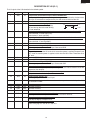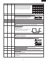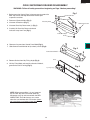
1
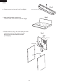
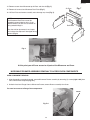
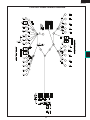
KB-3401LS
KB-3401LK
KB-3401LW
SUPPLEMENTAL SERVICE MANUAL
S76R266KB3401F
FREE STANDING RANGE
WITH MICROWAVE DRAWER
MODELS
KB-3401LW pictured
KB-3401LS
KB-3401LK
KB-3401LW
This is a supplemental Service Manual and is quite similar to the base models KB-3300JS/JK/JW; (S74R243KB330J). This
supplemental manual must be used in conjunction with the base model service manual for complete operation, service, safety
and replacement parts information.
WARNING TO SERVICE PERSONNEL:
This service manual is intended for use by persons having electrical and mechanical training and a level of
knowledge of these subjects generally considered acceptable in the appliance repair trade. Sharp Electronics
Corporation cannot be responsible, nor assume any liability, for injury or damage of any kind arising from the
use of this manual.
Microwave ovens contain circuitry capable of producing very high voltage and current. Contact with the
following parts may result in a severe, possibly fatal, electrical shock. (High Voltage Capacitor, High Voltage
Power Transformer, High Voltage Rectifier and Heat sink etc., and Magnetron, High Voltage Harness etc..)
TABLE OF CONTENTS
Page
PRECAUTIONS TO BE OBSERVED BEFORE AND DURING SERVICING TO
AVOID POSSIBLE EXPOSURE TO EXCESSIVE MICROWAVE ENERGY...................... INSIDE FRONT COVER
BEFORE SERVICING........................................................................................................ INSIDE FRONT COVER
WARNING TO SERVICE PERSONNEL.................................................................................................................. 3
MICROWAVE MEASUREMENT PROCEDURE...................................................................................................... 5
FOREWORD AND WARNING................................................................................................................................ 7
PRODUCT SPECIFICATIONS................................................................................................................................ 8
POWER CONNECTION........................................................................................................................................ 10
ANTI-TIP DEVICE................................................................................................................................................. 12
CONTROL LAYOUT.............................................................................................................................................. 13
SCHEMATICS....................................................................................................................................................... 14
TOUCH CONTROL PANEL ASSEMBLY............................................................................................................... 18
OVEN/MICROWAVE DRAWER DISASSEMBLY................................................................................................... 23
WIRING DIAGRAMS............................................................................................................................................. 33
PRINTED WIRING BOARDS................................................................................................................................ 39
PARTS LIST.......................................................................................................................................................... 44
PACKING AND ACCESSORIES........................................................................................................................... 56
SHARP ELECTRONICS CORPORATION
This document has been published to be used for after sales service only. The contents are subject to change without notice.
KB-3401LS
KB-3401LK
KB-3401LW
PRECAUTIONS TO BE OBSERVED BEFORE AND DURING SERVICING TO AVOID POSSIBLE EXPOSURE TO
EXCESSIVE MICROWAVE ENERGY
(a) Do not operate or allow the oven to be operated with the door open.
(b) Make the following safety checks on all ovens to be serviced before activating the magnetron or other microwave
source, and make repairs as necessary: (1) interlock operation, (2) proper door closing, (3) seal and sealing
surfaces (arcing, wear, and other damage), (4) damage to or loosening of hinges and latches, (5) evidence of
dropping or abuse.
(c) Before turning on microwave power for any service test or inspection within the microwave generating compartments, check the magnetron, wave guide or transmission line, and cavity for proper alignment, integrity, and
connections.
(d) Any defective or misadjusted components in the interlock, monitor, door seal, and microwave generation and
transmission systems shall be repaired, replaced, or adjusted by procedures described in this manual before
the oven is released to the owner.
(e) A microwave leakage check to verify compliance with the Federal Performance Standard should be performed
on each oven prior to release to the owner.
BEFORE SERVICING
Before servicing an operative unit, perform a microwave emission check as per the Microwave Measurement Procedure outlined in this service manual.
If microwave emissions level is in excess of the specified limit, contact SHARP ELECTRONICS CORPORATION immediately @1-800-237-4277.
If the unit operates with the door open, service person should 1) tell the user not to operate the oven
and 2) contact SHARP ELECTRONICS CORPORATION and Food and Drug Administration's Center for
Devices and Radiological Health immediately.
Service personnel should inform SHARP ELECTRONICS CORPORATION of any certified unit found with
emissions in excess of 4mW/cm2. The owner of the unit should be instructed not to use the unit until the
oven has been brought into compliance.
KB-3401LS
KB-3401LK
KB-3401LW
WARNING TO SERVICE PERSONNEL
Range units contain circuitry capable of producing very high voltage and current, contact
with following parts may result in a severe, possibly fatal, electrical shock.
(Example)
High Voltage Capacitor, High Voltage Power Transformer, Magnetron, High Voltage Rectifier
Assembly, High Voltage Harness, Heating Elements, etc..
Read the Service Manual carefully and follow all instructions.
Before Servicing
1. Disconnect the power supply cord remove cabinet.
2. Open the drawer and keep it open.
3. Discharge high voltage capacitor.
, and then
WARNING: RISK OF ELECTRIC SHOCK.
DISCHARGE THE HIGH-VOLTAGE CAPACITOR BEFORE SERVICING.
The high-voltage capacitor remains charged about 60
seconds after the oven has been switched off. Wait for
60 seconds and then short-circuit the connection of the
high-voltage capacitor (that is the connecting lead of the
high-voltage rectifier) against the chassis with the use of
an insulated screwdriver.
When the testing is completed,
1. Disconnect the power supply cord, and then remove
covers.
2. Open the drawer and keep it open.
3. Discharge high voltage capacitor.
4. Reconnect the leads to the primary of the power
transformer.
5. Reinstall the covers.
6. Reconnect the power supply cord.
7. Run the unit and check all functions.
After repairing
1. Reconnect all leads removed from components during
testing.
2. Reinstall the covers.
3. Reconnect the power supply cord.
4. Run the oven and check all functions.
Whenever troubleshooting is performed the power supply
must be disconnected. It may, in some cases, be necessary
to connect the power supply after the outer case has been
removed, in this event:
1. Disconnect the power supply cord, and then remove
neccessary covers.
2. Open the drawer and keep it open.
3. Discharge high voltage capacitor.
4. Disconnect the leads to the primary of the power
transformer.
5. Ensure that the leads remain isolated from other
components and oven chassis by using insulation tape.
6. After that procedure, reconnect the power supply cord.
Microwave ovens should not be operated empty. To test for
the presence of microwave energy within a cavity, place a
cup of cold water on the oven tray, close the drawer and set
the power to HIGH and set the microwave timer for two (2)
minutes. When the two minutes has elapsed (timer at zero)
carefully check that the water is now hot. If the water remains
cold carry out Before Servicing procedure and re-examine
the connections to the component being tested.
When all service work is completed and the oven is fully
assembled, the microwave power output should be checked
and a microwave leakage test should be carried out.
KB-3401LS
KB-3401LK
KB-3401LW
SAFE SERVICING PRACTICES
To avoid personal injury and/or property damage, it is important that Safe Servicing
Practices be observed. The following are some limited examples of safe practices:
1. DO NOT attempt a product repair if you have any doubts as to your ability to
complete it in a safe and satisfactory manner.
2. Before servicing or moving an appliance:
•
Remove the power cord from the electrical outlet, trip the circuit breaker to the
OFF position, or remove the fuse.
3. Never interfere with the proper operation of any safety device.
4. USE ONLY SHARP AUTHORIZED PARTS FOR THIS APPLIANCE.
SUBSTITUTIONS MAY DEFEAT COMPLIANCE WITH SAFETY
STANDARDS SET FOR HOME APPLIANCES.
5. GROUNDING : The standard color coding for safety ground wires is GREEN , or
GREEN with YELLOW STRIPES . Ground leads are not to be used as current
carrying conductors. It is EXTREMELY important that the service technician
reestablish all safety grounds prior to completion of service. Failure to do so will
create a hazard.
6. Prior to returning the product to service, ensure that:
•
•
•
•
•
All electrical connections are correct and secure
All electrical leads are properly dressed and secured away from sharp edges,
high-temperature components, and moving parts
All non-insulated electrical terminals, connectors, heaters, etc. are adequately
spaced away from all metal parts and panels
All safety grounds (both internal and external) are correctly and securely
connected
All panels are properly and securely reassembled
ATTENTION!!!
This service manual is intended for use by persons having electrical and mechanical training
and a level of knowledge of these subjects generally considered acceptable in the appliance
repair trade. Sharp Electronics Corporation cannot be responsible, nor assume any liability,
for injury or damage of any kind arising from the use of this manual.
KB-3401LS
KB-3401LK
KB-3401LW
MICROWAVE MEASUREMENT PROCEDURE
A. Requirements:
1) Microwave leakage limit (Power density limit): The power density of microwave radiation emitted by a microwave
oven should not exceed 1mW/cm2 at any point 5cm or more from the external surface of the oven, measured prior to
acquisition by a purchaser, and thereafter (through the useful life of the oven), 5 mW/cm2 at any point 5cm or more
from the external surface of the oven.
2) Safety interlock switches:
Primary interlock relay switch shall prevent microwave radiation emission in excess of the requirement as above
mentioned. Secondary interlock relay and door sensing switch shall prevent microwave radiation emission in excess
of
5 mW/cm2 at any point 5cm or more from the external surface of the oven.
B. Preparation for testing:
Before beginning the actual measurement of leakage, proceed as follows:
1) Make sure that the actual instrument is operating normally as specified in its instruction booklet.
Important:
Survey instruments that comply with the requirement for instrumentation as prescribed by the performance standard for
microwave ovens, 21 CFR 1030.10(c)(3)(i), must be used for testing.
2) Place the load of 275±15 ml (9.8 oz) of tap water initially at 20±5O C (68OF) in the center of the oven cavity.
The water container shall be a low form of 600 ml (20 oz) beaker with an inside diameter of approx. 8.5 cm (3-1/2 in.)
and made of an electrically nonconductive material such as glass or plastic.
The placing of this standard load in the oven is important not only to protect the oven, but also to insure that any leakage
is measured accurately.
3) Set the cooking control on Full Power Cooking Mode.
4) Close the drawer and select a cook cycle of several minutes. If the water begins to boil before the survey is completed,
replace it with 275 ml of cool water.
C. Leakage test:
Closed-drawer leakage test (microwave measurement):
1) Grasp the probe of the survey instrument and hold it perpendicular to the gap between the drawer and the body of the
oven.
2) Move the probe slowly, not faster than 1 in./sec. (2.5 cm/sec.) along the gap, watching for the maximum indication on
the meter.
3) Check for leakage at the drawer screen, sheet metal seams and other accessible positions where the continuity of the
metal has been breached (eg., around the switches, indicator, and vents).
While testing for leakage around the drawer, pull the drawer away from the front of the oven as far as is permitted by
the closed latch assembly.
4) Measure carefully at the point of highest leakage and make sure that the highest leakage is no greater than 4mW/cm2,
and that the primary interlock switch/secondary interlock relay does turn the oven OFF before any door movement.
KB-3401LS
KB-3401LK
KB-3401LW
NOTES
KB-3401LS
KB-3401LK
KB-3401LW
SERVICE MANUAL
FREE STANDING RANGE
PRODUCT DESCRIPTION
WITH MICROWAVE DRAWER
KB-3401LS
KB-3401LK / KB-3401LW
POWER CONNECTION
ANTI-TIP DEVICE
FOREWORD
This supplemental Manual has been prepared to provide Sharp Electronics Corp. Service Personnel with Operation and Service Information for the SHARP FREE STANDING RANGE WITH MICROWAVE
DRAWER, KB-3401LS/JK/JW.
SCHEMATICS
Models KB-3401LS, KB-3401LK, and KB-3401LW are quite similar
to models KB-3300JS/JK/JW (S74R243KB330J).
TOUCH CONTROL PANEL
It is recommended that service personnel carefully study the entire
text of this manual so that they will be qualified to render satisfactory
customer service.
COMPONENT REPLACEMENT
AND ADJUSTMENT PROCEDURE
Check the interlock switches and the door seal carefully. Special
attention should be given to avoid electrical shock and microwave
radiation hazard.
WIRING DIAGRAM
WARNING
Never operate the oven until the following points are ensured.
(A) The door is tightly closed.
(B) The door brackets and hinges are not defective.
(C) The door packing is not damaged.
(D) The door is not deformed or warped.
(E) There is not any other visible damage with the oven.
Servicing and repair work must be carried out only by trained service
personnel.
DANGER
Certain initial parts are intentionally not grounded and present
a risk of electrical shock only during servicing. Service
personnel - Do not contact the following parts while the appliance is energized;
High Voltage Capacitor, Power Transformer, Magnetron, High
Voltage Rectifier Assembly, High Voltage Harness;
If provided, Vent Hood, Fan assembly, Cooling Fan Motor.
All the parts marked “*” on parts list are used at voltages more
than 250V.
Removal of the outer wrap gives access to voltage above 250V.
All the parts marked “ ∆ ” on parts list may cause undue microwave
exposure, by themselves, or when they are damaged, loosened
or removed.
SHARP ELECTRONICS CORPORATION
SHARP PLAZA, MAHWAH,
NEW JERSEY 07430-2135
PARTS LIST
KB-3401LS
KB-3401LK
KB-3401LW
OVEN SPECIFICATION
ITEM
DESCRIPTION
Power Requirements 120 /208 - 120/240Volts / 46/50 Amperes
60 Hertz
Single phase, 3 wire grounded
Thermal Oven Heating Elemants Top - 3000W Bottom - 3000W Rear - 2500W
Case Dimensions Width 29-7/8"
Height 36"
Depth 27-5/16
Cooking Cavity Dimensions Width 22-5/8"
Height15-13/16"
3.6 Cubic Feet
Depth18"
Cook Top Heating Elements
Two 6" - 1200W
One 8" - 2000W
One 6"/9" - 1200/2400W One 6" - 100W
Control Complement Glass Touch Control System
Clock ( 1:00 - 12:59 )
Timer (0 - 99 min. 99 seconds)
Bake pad, Broil pad, Self Clean pad, Timed Cook pad, Number selection pads, Delay Start pad, Stop/Clear pad, Oven Light pad, Control Lock pad, Setup/Custom Help, Cooktop warm, Set/off, On, Control lock/on off, Convection, Timer/Hold to Clear and 3 min Plus.
Oven Cavity Light
Safety Standard
Weight
40W x 1
UL Listed
Approx. 260 lbs.
KB-3401LS
KB-3401LK
KB-3401LW
MICROWAVE DRAWER SPECIFICATION
ITEM
DESCRIPTION
Power Output 1000 watts (IEC TEST PROCEDURE)
Operating frequency of 2450MHz
Cooking Cavity Dimensions 1.0 Cubic Feet
Control Complement Width 17-11/32
Height 5-7/8"
Depth17-1/8"
Touch Control System
Clock ( 1:00 - 12:59 )
Timer (0 - 99 min. 99 seconds)
Microwave Power for Variable Cooking
Repetition Rate;
P-HI................................................... Full power throughout the cooking time
P-90...................................................................... approx. 90% of Full Power
P-80...................................................................... approx. 80% of Full Power
P-70...................................................................... approx. 70% of Full Power
P-60...................................................................... approx. 60% of Full Power
P-50...................................................................... approx. 50% of Full Power
P-40...................................................................... approx. 40% of Full Power
P-30 . ................................................................... approx. 30% of Full Power
P-20...................................................................... approx. 20% of Full Power
P-10...................................................................... approx.10% of Full Power
P-0...................................................... No power throughout the cooking time
START/MINUTE PLUS pad, Defrost pad, Number selection pad, Micro-warm/
Power Level pad, Timer/Clock pad,Stop/Clear pad, Sensor Reheat, Sensor
Popcorn, Sensor Cook, Setup/Custom Help.
Oven Cavity Light
Safety Standard
Yes
UL Listed
FCC Authorized
DHHS Rules, CFR, Title 21, Chapter 1, Subchapter J
KB-3401LS
KB-3401LK
KB-3401LW
POWER CONNECTION
208/240 VOLT CONNECTION INSTRUCTIONS
ACCESS TO TERMINAL BLOCK
The range can be set for 208V or 240V. The voltage setting for your
range is pre-set at 240V from the factory. Follow these steps to
change the voltage setting.
Loosen screw on rear access cover and pull down as illustrated in
Figure 6 to access terminal block wiring connection. To close, return
to original location and secure screw.
1 Locate the voltage switch on the lower back side of the
range.
strain-relief clamp
2 Remove the screw and rotate the switch plate 180 as indicated
in the Figure 3.
3 Reinsert the switch plate and replace screw as indicated
in Figure 4. The voltage setting is indicated by the visible
marking.
screw
208V
240V
screw
180
Figure 6
Figure 7
POWER CORD CONNECTIONS
4-WIRE CONNECTION INSTRUCTIONS-FIGURE 8
Figure 3
Before wiring the range, review the suggested power source location.
If connecting to a 4-wire electrical system for a new branchcircuit or mobile home use a 4-wire connection.
Figure 4
1 Follow the power supply kit manufacturer s Installation
Instructions supplied with the strain relief clamp and install.
See Figure 7.
3 & 4-WIRE ELECTRICAL WALL RECEPTACLE TYPES &
RECOMMENDED MOUNTING ORIENTATION ON WALL
Figure 5A illustrates 4-wire receptacle required for new and
remodeled installations.
2 Insert the end connectors for line 1, line 2 and neutral and
tighten securely to the terminal block.
Figure 5B illustrates 3-wire receptacle that is allowed for existing
installations.
IMPORTANT DO NOT LOOSEN the factory installed nut
connections which secure the range wiring to the terminal
block. Electrical failure or loss of electrical connection may
occur if these 3 nuts are loosened or removed.
3 You must disconnect the ground strap. Remove the factory
installed ground screw and plate to release the copper ground
strap from the frame of the range. Cut and discard the copper
ground strap and plate. KEEP the ground screw.
4-wire wall receptacle (14-50R)
3-wire wall receptacle (10-50R)
Figure 5A
Figure 5B
4 Connect the green ground wire lead with the eyelet to the frame
of the range with the ground screw using the same hole in the
frame where the ground screw was originally installed. See
Figure 8.
5 Make sure all screws are tightened securely and replace the
rear access cover. See Figure 6.
3-WIRE CONNECTION INSTRUCTIONS
For existing installations ONLY, refer to Figure 9.
1 Follow the power supply kit manufacturer s Installation
Instructions supplied with the strain relief clamp and install.
See Figure 7.
2 Insert the end connectors for line 1, line 2 and neutral and
tighten securely to the terminal block. See Figure 7.
IMPORTANT DO NOT LOOSEN the factory installed nut
connections which secure the range wiring to the terminal
block. Electrical failure or loss of electrical connection may
occur if these 3 nuts are loosened or removed.
10
KB-3401LS
KB-3401LK
KB-3401LW
3 Make sure all connections are tightened securely and replace
the rear access cover. See Figure 7.
connections. Tighten all 3 or 4-wire leads to the terminal block.
Follow wire locations shown in Figure 10.
IMPORTANT DO NOT LOOSEN the factory installed nut
connections which secure the range wiring to the terminal
block. Electrical failure or loss of electrical connection may
occur if these 3 nuts are loosened or removed.
GROUNDING INSTRUCTIONS- ONLY 3-WIRE CONNECTIONS:
A ground strap is installed on this range which connects the center
terminal of the neutral terminal block to the range chassis. The
ground strap is connected to the range by the center, lowest screw
See Figure 9. The ground strap must not be removed unless National
State or Local Codes do not permit use of a ground strap.
Note: For 3-wire permanent connection skip steps 3 and 4 and
continue with step 5.
3 Disconnect the ground strap. Remove the factory installed
ground screw and plate to release the factory installed copper
ground strap from frame of the range. Cut and discard the
copper strap from the terminal block. KEEP the ground screw,
ground plate and go to step 4.
Note: If the ground strap is removed for any reason, a separate
ground wire must be connected to the separate ground screw
attached to the range chassis and to an adequate ground source
3 & 4-WIRE PERMANENT WIRE CONNECTIONS
3–wire permanent connection – follow steps 1, 2 and 5 below.
4–wire permanent connection – follow all steps below.
Before wiring the range, review the suggested power source location
drawings in Figure 2. If connecting to a 4-wire electrical system:
4 Connect the green ground wire lead to the frame of the range
using the ground screw and plate as shown in Figure 11. Be sure
to install using the same hole in the frame where the ground
screw was originally installed.
1 Follow the manufacturer s Installation Instructions supplied
with the strain relief clamp and install.
5 Make sure all connections are tightened securely and replace
the rear access cover. See Figure 7.
2 Strip insulation away from the ends of the permanent wiring
for line 1, line 2 and neutral; also strip ground wire on 4-wire
Note: Non-terminated field wire compression connections must
be set at approximately 90 in./lbs.
4-WIRE CONNECTION
FOR 3 & 4-WIRE PERMANENT CONNECTIONS
terminal block
Connect
line 2
here.
terminal
block
neutral
A user supplied strainrelief clamp must be
installed at this location.
It requires 1 3/8-inches
(3.5 cm) diameter cord
kit hole.
c
k
gr e
en
Connect green insulated
copper ground wire with
ground screw here.
line 2
line 1
Connect neutral (white
or center) here.
red
bla
ite
wh
Connect line
1 here.
Cut ground strap.
Discard ground strap &
ground plate.
Note: Install strain-relief
clamp. Center or white
wire must always be
attached to the center
terminal on block.
ground strap
ground plate
ground
screw
Figure 10
Figure 8
3-WIRE CONNECTION
4-WIRE PERMANENT CONNECTION ONLY
ground
plate
proper ground for
4-wire permanent
connection
terminal block
Connect line
1 here.
Ground strap
Note: Install strain-relief
clamp. Center or white
wire must always be
attached to the center
terminal on block.
ground
screw
Connect
line 2
here.
ground
wire lead
Connect neutral (white
or center) here.
A user supplied strain-relief
clamp must be installed at
this location. It requires
1 3/8-inches (3.5 cm)
diameter cord kit hole.
Figure 11
Figure 9
11
KB-3401LS
KB-3401LK
KB-3401LW
2 DRILL PILOT HOLES AND FASTEN BRACKET
ANTI-TIP DEVICE
Drill a 1/8-inch pilot hole where screws are to be located. If bracket
is to be mounted to the wall, drill pilot hole at an approximate 20
degree downward angle. If bracket is to be mounted to masonry or
ceramic floors, drill a 5/32-inch pilot hole 1 3/4-inches deep. The
screws provided may be used in wood or concrete material. Use a
5/16 -inch nut-driver or flat head screwdriver to secure the bracket
in place.
NORMAL INSTALLATION STEPS
ANTI-TIP BRACKET INSTALLATION INSTRUCTIONS
IMPORTANT SAFETY WARNING
To reduce the risk of tipping of the range, the range must be secured
to the floor by properly installed Anti-Tip bracket and screws packed
with the range. Failure to install the Anti-Tip bracket will allow the
range to tip over if excessive weight is placed on an open door or if
a child climbs upon it. Serious injury might result from spilled hot
liquids or from the range itself.
FASTEN BRACKET
(WALL OR FLOOR MOUNTING)
Max 1 1/4"
Leveling Leg
Wall Mount
If range is ever moved to a different location, the Anti-Tip bracket
must also be moved and installed with the range. Instructions are
provided for installation in wood or cement fastened to either the floor
or wall. When installed to the wall, make sure that screws completely
penetrate dry wall and are secured in wood or metal. When fastening
to the floor or wall, be sure that screws do not penetrate electrical
wiring or plumbing.
Wall Plate
Floor Mount
Anti-Tip Bracket
Figure 16
FASTEN BRACKET
1 LOCATE THE BRACKET - USING THE TEMPLATE
(FLOOR MOUNTING ONLY)
More Than
1 1/4"
Leveling Leg
The bracket may be located on either the left or right side of the
range. Use the information below to locate the bracket if template
is not available.
Wall
Floor Mount
Anti-Tip Bracket
Figure 17
3 LEVEL AND POSITION RANGE
Level range by adjusting the (4) leveling legs with a wrench. Note:
A minimum clearance of 1/8-inch is required between the bottom
of the range and the leveling leg to allow room for the bracket. Use
a level to check your adjustments. Plug range into properly prepared
electrical receptacle or if hard wired, check that it was completed
properly. Check door condition for evenness and stability. Slide
range back into position.
Visually check that rear leveling leg is inserted into and fully secured
by the Anti-Tip bracket by looking underneath the range with a
flashlight and carefully attempt to tilt it forward.
Figure 15
Mark the floor or wall where left or right side of the range will be
located. If rear of range is against the wall or no further than 1 1/4 inches from wall when installed, you may use the wall or floor mount
method. If molding is installed and does not allow the bracket to fit
push against the wall, remove molding or mount bracket to the floor.
For wall mount, locate the bracket by placing the back edge of the
template against the rear wall and the side edge of template on the
mark made referencing the side of the range. Place bracket on top
of template and mark location of the screw holes in wall. If rear of
range is further than 1 1/4-inches from the wall when installed, attach
bracket to the floor. For floor mount, locate the bracket by placing
back edge of the template where the rear of the range will be located.
Mark the location of the screw holes, shown in template.
1 5/8" to edge
of bracket
Range Slide
Figure 18
12
KB-3401LS
KB-3401LK
KB-3401LW
GLASS CERAMIC COOKTOP
WARM ZONE
RADIANT
SURFACE UNIT
RADIANT
SURFACE UNIT
RADIANT
SURFACE UNIT
RADIANT
SURFACE UNIT
HOT SURFACE INDICATOR LIGHTS
CONTROL KNOBS
CONTROL KNOBS
CONTROL PANEL
OFF
LO
OFF
HI
LO
OFF
HI
LO
OFF
SMALL
HI
LARGE
HI
HI
MED
Cooktop
MED
MED
Cooktop
MED
OVEN
MED
KEY GLASS
KB-3401LS
3
MICROWAVE
LO
LO
Schematic-Off Condition
KB-3401LS
KB-3401LK
KB-3401LW
N
WHT
WHT
YLW
RED RED
YLW
1a
BRN
2a
2
INDICATOR LIGHT
PROTECTOR
RED
RED
RED
P1
RED
WHT
L2
RED
BLK
L2
L1
BLK
RED
WHT
CONTROL UNIT
OVEN
C3
D1
RED
OVEN
THERMAL
CUT-OUT
ORG
RED
C7
ORG
MG
THERMAL
CUT-OUT
C5
D3
D5
E6 E3
RY-C
ORG
E5
RY-B
RED
RED
COM.
L1
CONTROL
S1
S2
YLW
4
INSIDE
OUTSIDE
P1B /
4
N
RED
COM.
A4
A1 A2
LOW VOLTAGE
TRANSFORMER
A6
CAPACITOR
1.00uF
AC 2300V
4a
RIGHT FRONT
SURFACE
ELEMENT
L2 /
P1
RED
YLW
L
N.O.
BRN
WHT P1A /
4A
2a
RED
RED
RED
CONTROL UNIT
C1
WHT
RED
L2 /
P1 RED
RED
L2
RY9
BLK
YLW
BLK P2
P
2
PROTECTOR
1a
INDICATOR LIGHT
H2 /
2
WHT
L2 /
P1
WHT
RED
RED
RED
RED
ORG
YLW
L1 /
P2
WHT
YLW
3
WARMER
SURFACE
ELEMENT
2
H2 /
2
BRN
RF
RED
B1
B3
RED
H2 /
P1 /
4
2
YLW 2
1a
2a
RIGHT REAR
PROTECTOR
SURFACE
ELEMENT
WHT
YLW
P1 /
4
1a
2a
LEFT FRONT
SURFACE PROTECTOR
ELEMENT
LEFT REAR
SURFACE
ELEMENT
P1 /
4
2
1a
2a
PROTECTOR
HOT SURFACE LIGHT
RR
LR
RED
N.O.
YLW
M8
BRN
RY3
WHT
RY4
COM.
BLU
H1 /
4 WHT
P YLW
BLK
YLW
WHT
YLW
BRN
BLU
LF
14
RED
VOLTAGE SWITCH
BRN
OVEN THERMAL
CUT-OUT (THERMAL OVEN)
WHT
CONTROL
L1 /
P2
BLK
H1 /
4
P
CONTROL
L1 /
P2
H1 /
4
WHT
1b /
H
CONTROL
2b /
S
BRN
YLW
1b /
H BLU
BLK
YLW
BRN
BRN
POWER TRANSFORMER
WHT
BLK
TOP HEATER
BLK
BLK
ORG
BLK
ORG
BLK
BLK
BLK
BLU
2b /
S
1b /
H
YLW
BLK
YLW
YLW
2b /
S
1b /
H YLW
RY7
RED
BLK
YLW
M4
BLK
BLK
BLK N.O.
RED
ORG
OL
RY8
CONV. MOTOR
SECONDARY INTELOCK SWITCH
BLK
OVEN LAMP
YLW
2b /
S
L
BLU
WHT
MAGNETRON
RECTIFIER
BLK
RED
BLK
BLK
BOTTOM HEATER
MONITOR SWITCH
RED
BLU
RED
BRN
LM
WHT
BLK
BLK
CONV. HEATER
N.O.
OVEN LAMP
GRY
OL
WHT
WHT
PRIMARY INTERLOCK
RELAY
RED
ORG
WHT
RY2
STIRRER MOTOR
RY1
FAN MOTOR
WHT
WHT
BLK
BLK
BLK
L1
M3
BRN
COM.
F2
CM
RED
GRN
YLW
FM
WHT
WHT
M9
NOISE SUPRESSION COIL
M10
YLW
DOOR LOCK
MOTOR
SWITCH
RED
M5
RED
DOOR
SWITCH
LINE CROSS CAPACITOR 1.0uF 250V
M12 RY6
THERMISTOR
MICROWAVE DRAWER
WHT M1
WHT
F3
WHT
WHT
RY5
F1
RY10
BLK
FM
ORG
RED
ORG
ORG
SM
WHT
BLK
BLU
BLK
BLU
BLU
HOT SURFACE
LIGHT
SWITCHES
NOTES:
FUSE
20A
BLK
1. Circuits / wire colors are subject to change without notice.
2. Terminal that is located on the right side on lamp sockets back view
must be connected to neutral wire.
RESISTOR 470 kohm 1/2W
CLOSS FLOW
FAN MOTOR
DOOR
SENSING
SWITCH
YLW
YLW
M11
ORG
LINE BYPASS CAPACITOR
0.0033uF 250V
LINE BYPASS CAPACITOR
0.0033uF 250V
DOOR LOCK
MOTOR
HUMIDITY
SENSOR
YLW
YLW
YLW
YLW
YLW
BLK
BLK
BLK
COOK TOP
WHT
KB-3401LS
KB-3401LK
KB-3401LW
COOK TOP SCHEMATIC (DETAIL)
RED
RED
RED
RED
RED
BLK
BLK
BLK
BLK
YLW
CONTROL
S1
S2
INDICATOR LIGHT
YLW
RED
RED
YLW
YLW
RED RED
4
L1 /
P2
WHT P1A /
4A
P1
2
2a
RED
PROTECTOR
RED
WHT
RIGHT FRONT
SURFACE
ELEMENT
P
H1 /
4 WHT
WHT
YLW
YLW
CONTROL
YLW
ORG
YLW
YLW
INSIDE
OUTSIDE
YLW
4a
BRN
1a
P1B /
4
BLK P2
L2
RED
L2
L1
P1 /
4
2
YLW
1a
2a
RIGHT REAR
PROTECTOR
SURFACE
ELEMENT
H2 /
2
L2 /
P1
RED
WHT
N
3
2
WARMER
SURFACE
ELEMENT
BLK
L1 /
P2
P YLW
YLW
1a
2a
PROTECTOR
INDICATOR LIGHT
YLW
RED
ORG
BLK
BLK
YLW
L1 /
P2
YLW
YLW
BLK
CONTROL
P
H1 /
4
WHT
H2 /
2
2
1a
2a
LEFT FRONT
SURFACE PROTECTOR
ELEMENT
LEFT REAR
SURFACE
ELEMENT
P1 /
4
2
YLW
YLW
CONTROL
WHT
P1 /
4
RED
WHT
L2
H2 /
2
1a
2a
PROTECTOR
L2 /
P1
RED
BRN
HOT SURFACE LIGHT
BLK
BLU
BLK
BLU
BLK
BLU
BLU
2b /
S
1b /
H BRN
2b /
S
1b /
H BLU
2b /
S
1b /
H BLK
2b /
S
1b /
H YLW
RR
YLW
BRN
YLW
BLU
YLW
BLK
YLW
YLW
RF
LR
LF
HOT SURFACE
LIGHT
SWITCHES
N
L2 /
P1 RED
WHT
WHT
15
WHT
BLK
YLW
WHT
H1 /
4
KB-3401LS
KB-3401LK
KB-3401LW
MICROWAVE DRAWER SCHEMATIC (DETAIL)
L2
WHT
BLK
L1
BLK
RED
L
L
FUSE
20A
RESISTOR 470 kohm 1/2W
LINE CROSS CAPACITOR 1.0uF 250V
NOISE SUPRESSION COIL
LINE BYPASS CAPACITOR
0.0033uF 250V
LINE BYPASS CAPACITOR
0.0033uF 250V
RED
OVEN
THERMAL
CUT-OUT
DOOR
SENSING
SWITCH
WHT M1
ORG
M3
BRN
BRN
F2
ORG
F3
COM.
RED
BLK
RED
CONTROL UNIT
HUMIDITY
SENSOR
MG
THERMAL
CUT-OUT
BLK
F1
FM
FAN MOTOR
WHT
ORG
ORG
ORG
RED
ORG
RED
STIRRER MOTOR
WHT
RY1
RY2
PRIMARY INTERLOCK
RELAY
COM.
OL
WHT
N.O.
SM
WHT
RY5
BLK
C1
SECONDARY INTELOCK SWITCH
WHT
GRN
OVEN LAMP
N.O.
RED
RED
RED
BRN
RED
RED
POWER TRANSFORMER
BLK
A4
A1 A2
BLU
CAPACITOR
1.00uF
AC 2300V
WHT
16
B3
MAGNETRON
B1
RECTIFIER
BLK
WHT
YLW
LOW VOLTAGE
TRANSFORMER
A6
VOLTAGE SWITCH
BRN
MONITOR SWITCH
RANGE SCHEMATIC (DETAIL)
L2
RED
RED
N
BLK
RED
WHT
BLK
DOOR
SWITCH
RED
M5
RED
YLW
BRN
ORG
YLW
C3
FM
M11
M12 RY6
ORG
CLOSS FLOW
FAN MOTOR
M10
M8
THERMISTOR
WHT
WHT
M9
RY9
BLK
RED
D1
CM
RED
CONTROL UNIT
DOOR LOCK
MOTOR
SWITCH
M4
BLU
CONV. MOTOR
BRN
LM
RED
WHT
WHT
RY8
C7
DOOR LOCK
MOTOR
RY7
WHT
WHT
ORG
OL
C5
OVEN LAMP
RY10
D3
YLW
RY-C
E6 E3
WHT
GRY
ORG
BLK
CONV. HEATER
BLK
BLK
RY-B
E5
WHT
RED
D5
WHT
WHT
RY3
BLU
BOTTOM HEATER
COM.
BLK
BLK N.O.
BLK
BLK
BLK
TOP HEATER
RED
COM.
RY4
N.O.
BRN
RED
RED
17
L1
BLK
BLK
KB-3401LS
KB-3401LK
KB-3401LW
KB-3401LS
KB-3401LK
KB-3401LW
TOUCH CONTROL PANEL ASSEMBLY
OUTLINE OF TOUCH CONTROL PANEL
The touch control section consists of the following units.
(1)Keyboard unit
(2)Control Unit
(3)Power unit
The principal functions of these units and the signals communicated among them are explained below.
In addition, the synchronizing signal is available in order
to compose a basic standard time in the clock circuit.
Symbol Voltage VC +5V Application
LSI(IC1)
12) Relay Circuit
A circuit to drive the magnetron, fan motor, stirrer motor,
convection motor, door lock motor, bottom heater, top
heater, convection heater and light the oven lamp.
Keyboard unit
The keyboard unit is composed of a matrix, signals generated in the LSI are sent to the keyboard unit . When a key
pad is touched, a signal is completed through the keyboard
unit and passed back to the LSI to perform the function that
was requested.
13) Buzzer Circuit
The buzzer is responsive to signals from the LSI to
emit audible sounds (key touch sound and completion
sound).
Control Unit and Power Unit
Control unit consists of LSI, IC, reset circuit, indicator circuit,
power source circuit, relay circuit, buzzer circuit, synchronizing signal circuit, keyboard unit circuit, humidity sensor
circuit and back light circuit.
14) Synchronizing Signal Circuit
The power source synchronizing signal is available in
order to compose a basic standard time in the clock
circuit.
It accompanies a very small error because it works on
commercial frequency.
1) IC1 (LSI)
This is a microcomputer, responsible for controlling the
entire control unit.
15) Door Sensing Switch (Microwave drawer)
A switch to “tell” the LSI if the drawer is open or
closed.
2) IC2
This is the IC to drive the Liquid Crystal Display
(LCD1).
16) Door Switch (Oven)
A switch to “tell” the LSI if the oven door is open or
closed.
3) IC3
This is the IC to drive the Liquid Crystal Display
(LCD2).
17) Door Lock Monitor Switch (Oven)
A switch to “tell” the LSI if the oven door is locked or
not.
4) IC4
This is the IC to judge the selected key.
18) Door Position Switch Front / Rear
The switch to “tell” the position of the Microwave drawer
door.
5) IC5
This is the IC to amplify the signal from the humidity
sensor.
19) Back Light Circuit
A circuit to drive the back light (Light emitting diodes
LD1- LD6).
6) IC6
This is memory IC.
20) Cook Top Warmer Indicator Circuit
A circuit to drive the indicator (LD10) for Cook Top
Warmer.
7) IC7
This is the IC to drive the relays.
8) IC8
This is the IC to drive the relays.
21) Humidity Sensor Circuit
This circuit detects moisture of the cooking food to allow
its automatic cooking.
9) Reset Circuit
This circuit generates a signal which resets the LSI (IC1)
to the initial state when power is supplied.
22) Temperature Measurement Circuit : (OVEN
THERMISTOR)
The temperature in the oven cavity is sensed by the
thermistor. The variation of resistance according to
sensed temperature is detected by the temperature
measurement circuit and the result applied to LSI. The
LSI uses this information to control the relay and display
units.
10) Indicator Circuit
A circuit to drive the Liquid Crystal Displays (LCD1,
LCD2).
11) Power Source Circuit
This circuit generates voltages necessary in the control
unit from the AC line voltage.
18
KB-3401LS
KB-3401LK
KB-3401LW
DESCRIPTION OF LSI (IC-1)
The I/O signal of the LSIis detailed in the following table.
Pin No.
Signal
I/O
Description
Temperature measurement input: OVEN THERMISTOR.
By inputting DC voltage corresponding to the temperature detected by the thermistor,
this input is converted into temperature by the A/D converter built into the LSI.
2
AN4
IN
Turminal not used.
3
AN3
OUT Door lock motor driving signal.
ON
H: +5V
During
To turn on and off shut-off relay(RY8).
door lock
OFF
motor
driving
“H”level during door lock motor driving
L: GND
“L” level otherwise
Input signal which communicates the oven door locked information to LSI.
4
AN2
IN
Door unlocked; “H” level signal(+5V).
Door locked; “L” level signal(0V).
Input signal which communicates the oven door unlocked information to LSI.
5
AN1
IN
Door locked; “H” level signal(+5V).
Door unlocked; “L” level signal(0V).
6
AN0
IN
Turminal not used.
7
CNVSS
IN
Power source voltage: 0V (GND).
VC voltage of power source circuit input. Connected GND.
Auto clear terminal.
8
RESET
IN
Signal is input to reset the LSI to the initial state when power is applied. Temporarily set
to “L” level the moment power is applied, at this time the LSI is reset. Thereafter set at
“H” level.
9
P62
OUT Memory (EEPROM) clock out.
10
P61
IN/OUT Memory (EEPROM) data input/output.
11
VSS
IN
Power source voltage: 0V (GND).
VS voltage of power source circuit input. Connected GND.
12
XIN
IN
Internal clock oscillation frequency setting input.
The internal clock frequency is set by inserting the ceramic filter oscillation circuit with
respect to Xout terminal.
13
XOUT
OUT Internal clock oscillation frequency control output.
Output to control oscillation input of Xin.
14
VCC
IN
Power source voltage: +5V.
VC voltage of power source circuit input.
15
P60
IN
Plus signal coming from the Microwave drawer door open-close motor is input into P60
as revolution number.
16
P37
OUT Terminal not used.
17
P36
OUT Terminal not used.
18
P35
OUT Terminal not used.
19
P34 OUT Terminal not used.
20
RXD2
IN
Input terminal to check the data of display.
Data signal from IC-3 is input to RXD2 to check the flow of the data.
21
TXD2
IN
Output terminal to send IC-2 the data.
The data of display is output to IC-2.
22
SCLK2
OUT Clock timing signaI output terminal.
Clock timing signal is sent to IC-2 and IC-3.
1
AN5
IN
19
KB-3401LS
KB-3401LK
KB-3401LW
Pin No.
Signal
I/O
23
P30
OUT
24 - 27 COM3 - COM0 OUT
28
VL3
IN
29 - 34 P27- P22 OUT
35
P21
OUT
36
P120
OUT
37
P17
OUT
38
P16
OUT
39
P15
OUT
40
P14
OUT
41
P13
OUT
42
P12
OUT
43
P11
OUT
44
P10
OUT
45
P07
OUT
46
P06
OUT
47
P05
OUT
Description
Signal to reset LSI.
Signal is output to reset IC-2, IC-3 and IC-4.
Terminal not used.
Connected VC (+5V).
Terminal not used.
Terminal not used.
Convection heater relay driving signal.
ON
To turn on and off relay(RYC).
“H” level: During convection heater relay ON.
“L” level: During convection heater relay OFF.
Bottom heater relay driving signal.
ON
To turn on and off relay(RYB).
“H” level: During bottom heater relay ON.
“L” level: During bottom heater relay OFF.
Cook top warmer driving signal.
ON
To turn on and off relay(RY10).
“H” level: During cook top warmer ON.
“L” level: During cook top warmer OFF.
Oven convection motor driving signal.
ON
To turn on and off relay(RY9).
“H” level: During convection motor ON.
“L” level: During convection motor OFF.
Door lock motor driving signal.
ON
To turn on and off relay(RY8).
“H” level: During door lock motor ON.
“L” level: During door lock motor OFF.
Oven lamp (Oven) driving signal.
ON
To turn on and off relay(RY7).
“H” level: During oven lamp ON.
“L” level: During oven lamp OFF.
Fan motor (Oven) driving signal.
ON
To turn on and off relay(RY6).
“H” level: During fan motor ON.
“L” level: During fan motor OFF.
Fan motor (Drawer) driving signal.
ON
To turn on and off relay(RY5).
“H” level: During fan motor ON.
“L” level: During fan motor OFF.
Top heater driving signal.
ON
To turn on and off relay(RY4).
“H” level: During top heater ON.
“L” level: During top heater OFF.
Oven common relay driving signal.
ON
To turn on and off relay(RY3).
“H” level: During oven common relay ON.
“L” level: During oven common relay OFF.
Oven lamp and stirrer motor driving signal.
ON
To turn on and off relay(RY1).
“H” level: During oven lamp and stirrer motor ON.
“L” level: During oven lamp and stirrer motor OFF.
Magnetron high-voltage circuit driving signal.
To turn on and off the cook relay(RY2). In 100% power operation,
20
H: +5V
OFF
L: GND
H: +5V
OFF
L: GND
H: +5V
OFF
L: GND
H: +5V
OFF
L: GND
H: +5V
OFF
L: GND
H: +5V
OFF
L: GND
H: +5V
OFF
L: GND
H: +5V
OFF
L: GND
H: +5V
OFF
L: GND
H: +5V
OFF
L: GND
H: +5V
OFF
L: GND
KB-3401LS
KB-3401LK
KB-3401LW
Pin No.
Signal
I/O
48-52
P04-P00 OUT
53
P57
OUT
Description
the signals holds “H” level during microwave cooking and “L” level while not cooking. In other cooking
modes (90%, 80%, 70%, 60%, 50%, 40%, 30%,
20%, 10%, 0%) the signal turns to “H” level and “L”
level in repetition according to the power level.
Microwave cooking mode
VARI MODE
Other cooking mode
ON TIME OFF TIME ON TIME OFF TIME
100% power
32 sec.
0 sec.
60sec.
0ec.
90% power
30 sec.
2 sec. 54sec.
6sec.
80% power
26 sec.
6 sec.
48sec.12sec.
70% power
24 sec.
8 sec.
42sec.18sec.
60% power
22 sec.10 sec.
36sec.
24sec.
50% power18 sec.14 sec.
30sec.
30sec.
40% power16 sec.16 sec.
24sec.
36sec.
30% power12 sec.
20 sec.18sec.
42sec.
20% power
8 sec.
24 sec.12sec.
48sec.
10% power
6 sec.
26 sec.
4sec.
56sec.
0% power0 sec.
32 sec.
0sec.
60sec.
Used for initial balancing of the bridge circuit (absolute humidity sensor).
Common relays driving signal. (Square Waveform : 60Hz)
To turn on and off the shut-off relays (RY1 and
RY3). The square waveform voltage is delivered
to the relays (RY1 and RY3) driving circuit.
Signal coming from key unit.
Signal coming from key unit.
Signal coming from key unit.
To input signal which communicates the oven door open/close information to
LSI.
Door open "H" level signal (+5V). Door close "L" level signal (GND).
Signal to sound buzzer.
A: Key touch sound.
B: Completion sound.
H : +5V
C: When the oven stops so that the food can be
checked in Automatic cooking mode.
6.7 msec.
H: +5V
L: GND
During cooking
54
55
56
57
P56
TXD1
RXD1
P53 IN
IN
IN
IN
58
P52
OUT
L : GND
6.7 msec.
59
P51
IN
60
INT0
IN
Input signal which communicates the drawer door open/ close information to
LSI.
Door opened; “H” level signal(+5V).
Door closed; “L” level signal(0V).
Signal to synchronize LSI with commercial power source frequency.
0. sec
This is the basic timing for all real time processing of LSI.
A
2.0 sec
B
.0 sec
.0 sec
H: +5V
C
L: GND
61
AVSS
IN
62
VREF
IN
63
AN7
IN
64
AN6
IN
A/D converter power source voltage.
The power source voltage to drive the A/D converter in the LSI.
Reference voltage input terminal.
A reference voltage applied to the A/D converter in the LSI. Connected to +5V.
AH sensor input.
This input is an analog input terminal from the AH sensor circuit, and connected to the
A/D converter built into the LSI.
Used for initial balancing of the bridge circuit (absolute humidity sensor). This input is
an analog input terminal from the AH sensor circuit, and connected to the A/D converter
built into the LSI.
21
KB-3401LS
KB-3401LK
KB-3401LW
PRECAUTIONS FOR USING LEAD-FREE SOLDER
1. Employing lead-free solder
The "Main PWB" of this model employs lead-free solder. This is indicated by the "LF" symbol printed on the PWB and
in the service manual. The suffix letter indicates the alloy type of the solder.
Example:
Indicates lead-free solder of tin, silver and copper.
2. Using lead-free wire solder
When repairing a PWB with the "LF" symbol, only lead-free solder should be used. (Using normal tin/lead alloy solder
may result in cold soldered joints and damage to printed patterns.)
As the melting point of lead-free solder is approximately 40oC higher than tin/lead alloy solder, it is recommend that
a dedicated bit is used, and that the iron temperature is adjusted accordingly.
3. Soldering
As the melting point of lead-free solder (Sn-Ag-Cu) is higher and has poorer wettability, (flow), to prevent damage
to the land of the PWB, extreme care should be taken not to leave the bit in contact with the PWB for an extended
period of time. Remove the bit as soon as a good flow is achieved. The high content of tin in lead free solder will cause
premature corrosion of the bit. To reduce wear on the bit, reduce the temperature or turn off the iron when it is not
required.
Leaving different types of solder on the bit will cause contamination of the different alloys, which will alter their
characteristics, making good soldering more difficult. It will be necessary to clean and replace bits more often when
22
KB-3401LS
KB-3401LK
KB-3401LW
OVEN / MICROWAVE DRAWER DISASSEMBLY
WARNING: Follow all safety precautions beginning on Page 2 before proceeding!
Fig. 1
1. Before removing Control Panel, take measures to protect the Cook Top surface and keep Microwave Drawer open to prevent scratches.
2. Remove all Control Knobs (Fig 1).
3. Unscrew all Retainers (Fig 1).
Control Knobs
Retainers
Glass Key Deco
GND Deco Screw
4. Unscrew Glass Key Deco screw (1) (Fig 1).
5. Carefully lift Glass Key Deco and unhook
Indicator Lamp from Lens (Fig 1).
Lens
Indicator Lamps
6. Remove all screws from Control Panel Mold (Fig 2).
7. Slide Control Panel Mold to left (to unlock) and lift (Fig 2).
Fig. 2
Control Panel Mold
Gasket
8. Remove Gasket from Key Fixing Angle (Fig 3).
9. Lift Key Fixing Mold and carefully unhook all Molex’s, ground wire and C/P wiring (Fig 3).
Fig. 3
Key Fixing Angle
NOTE: When reassembling, it is very important
that all Cook Top wires are tucked under the
Microwave cavity lip and secured with the RED
WIRE STRAP. The 240v harness can create
noise that can interfere with C/P function (example: intermittent or no keyboard operation).
23
KB-3401LS
KB-3401LK
KB-3401LW
Fig. 4
10. Remove screws from Control Panel Frame (Fig 4).
Control Panel Frame
11. Slide Cook Top forward to unlock from
Fig. 5
shoulder screws, then remove or reposition (Fig. 5).
12. Remove electrical cover and screws holding the select switch from back plate. Then remove all screws on back plate and carefullyremove back/side panels (Fig. 6).
Fig. 6
Back Panel
Select Switch
Side Panels
24
KB-3401LS
KB-3401LK
KB-3401LW
14. Remove screws from Microwave top Air Duct and take off (Fig. 7).
15. Remove all screws from Microwave Back Plate (Fig. 7).
Air Duct
Fig. 7
16. Lift Back Plate and remove carefully not to damage any wires (Fig. 7).
NOTE:
The Microwave Back Plate cannot be
completely removed due to wiring. If you need to remove, you will have to unhook all
wiring routed through it.
Back Plate
Also, the cushion placement is very important and must be replaced if damaged during
removal (Fig. 8).
Fig. 8
At this point, you will have access to all parts of the Microwave and Oven. MICROWAVE DRAWER ASSEMBLY REMOVAL TO ACCESS OVEN COMPONENTS
OVEN COMPONENT REMOVAL
1. After dissaembly as previously stated, remove Microwave Drawer assembly by removing (2) screws (right & left) from
front of Microwave Baseplate (Fig. R-1).
2. Unhook wires from Range Oven to Microwave Drawer, remove Drawer assembly from Oven.
You now have access to Range Oven components.
screw
Fig. R-1
25
KB-3401LS
KB-3401LK
KB-3401LW
STOP SWITCH, SECONDARY INTERLOCK SWITCH AND MONITOR SWITCH REMOVAL
1. Disconnect the power supply cord.
2. Open the drawer and keep it open.
3. To discharge the high voltage capacitor, wait for 60
seconds.
4. Remove the Cook Top.
5. Remove the Cook Top Stay (right or left).
6. Remove the screw holding the latch hook to the oven
flange.
7. Remove the latch hook from the oven flange.
8. Disconnect the wire leads of each switch.
9. Remove each switch from the latch hook by pushing the
one (1) stopper tab holding each switch.
10.Now, each switch is free.
Re-install
1. Re-install each switch in its place.The secondary interlock
switch is in the lower position and the monitor switch is
in the top position, located on the left side of the unit.
The door sensing switch by itself on the right side of the
unit.
2. Re-connect wire leads to each switch. Refer to pictorial
diagram.
3. Secure the latch hooks with mounting screws to oven
flange.
4. Make sure that the monitor switch is operating properly
and check continuity of the monitor circuit. Refer to
chapter "Test Procedure" and "Adjustment procedure".
Latch Hook Right
Latch Hook Left
STOP SWITCH, SECONDARY INTERLOCK SWITCH AND MONITOR SWITCH ADJUSTMENT
1. Disconnect the power supply cord.
2. Open the drawer and keep it open.
3. To discharge the high voltage capacitor, wait for 60
seconds.
4. Remove the Cook Top.
5. Remove the Cook Top Stay (right or left). If the door
sensing switch, secondary interlock switch and monitor
switch do not operate properly due to a misadjustment,
the following adjustment should be made.
6. Loosen the screw holding latch hook to the oven cavity
flange.
7. With drawer closed, adjust latch hook by moving it back
and forth, and up and down. In and out play of the door
allowed by the upper and lower position of the latch hook
should be less than 0.5mm. The vertical position of the
latch hook should be adjusted so that the secondary
interlock switch is activated with the drawer closed. The
horizontal position of the latch hook should be adjusted
so that the monitor switch and drawer sensing switch
are activated with the drawer closed.
8. Secure the screws with washers firmly.
9. Check all of the switches operation. If any switch has
not activated fully, you will need to adjust the slide rail
attached to the Microwave cavity.
10.This is done by following the steps to remove the
"DRAWER/SLIDE RAIL REMOVAL" on page 27. After
you have removed the slide rails, loosen the "2" screws
holding the slide rail to the Microwave cavity and tilt the
front end up and the rear end down, then tighten the
screws (Fig. S-1).
26
11.Check and assure that the cap nuts on the Drawer
Support Angles are centered when passing through the
cavity face plate.
After adjustment, check the following.
1. In and out play of door remains less than 0.5mm when
in the latched position. First check upper position of latch
hook, pushing and pulling upper portion of drawer toward
the oven face. Then check lower portion of the latch hook,
pushing and pulling lower portion of the door toward the
oven face. Both results (play in the door) should be less
than 0.5mm.
2. The secondary interlock switch switch interrupt the circuit
before the door can be opened.
3. Monitor switch contacts close when door is opened.
4. Door sensing switch contacts open when door is
opened.
5. Reassemble the unit and check for microwave leakage
around door with an approved microwave survey meter.
(Refer to Microwave Measurement Procedure.
Fig. S-1
DRAWER/SLIDE RAIL REMOVAL
DRAWER ASSEMBLY AND CHOKE REMOVAL
1. Disconnect the power supply cord.
2. Open the drawer and keep it open.
3. To discharge the high voltage capacitor, wait for 60
seconds.
4. Remove the both right and left Cook Top Stays.
5. Remove (2) Drawer Support Covers from Choke Cover
as shown in (Fig. D-1).
6. Insert a putty knife (thickness of about 0.5mm) into the
gap between the choke cover and the door frame.
7. Carefully slide choke cover away from drawer as far as
possible.
8. Remove (6) screws from all (3) drawer Support Angles
as shown in (Fig. D-2).
9. Unhook Drawer Support Angles from drawer, then
remove.
10.Now, the door assembly is free and the Choke Cover
can now be removed.
Fig. D-1
KB-3401LS
KB-3401LK
KB-3401LW
NOTE:
To remove only the
Microwave Drawer, follow steps
1, 2, 5, 8, 9 & 10
as instructed under
"DRAWER ASSEMBLY AND
CHOKE REMOVAL".
Fig. D-2
DRAWER SUPPORT ANGLE REMOVAL
1. Remove Drawer Assembly and Choke Cover as stated
in "DRAWER ASSEMBLY AND CHOKE REMOVAL".
2. Remove (2) screws from right or left Latch Angle
Assembly, then remove Angle assembly (Fig. D-4).
3. Separate Slide Rails by moving inside lever of Slide
Rails. The Slide Rail will now separate by pulling straight
forward and out (Fig. D-3).
4. At this point, you can replace either Latch Angle Assy
or Latch Angles.
To reassemble, just reverse the above order.
After reassembly, do the following.
(A) Make sure that drawer sensing switch, secondary
interlock switch and monitor switch are operating
properly. (Refer to chapter "Test Procedures".)
(B) An approved microwave survey meter should be
used to assure compliance with proper microwave
radiation emission limitation standards.
Fig. D-3
After any servicing, make sure of the following :
1. Drawer latch heads smoothly catch latch hook through
latch holes and that latch head goes through center of
latch hole.
2. Deviation of door alignment from horizontal line of cavity
face plate is to be less than 1.0mm.
3. Drawer is positioned with its face pressed toward cavity
face plate.
4. Reassemble the unit and check for microwave leakage
around drawer with an approved microwave survey meter.
(Refer to Microwave Measurement Procedure.)
Fig. D-4
Note: The drawer on a microwave oven is designed to
act as an electronic seal preventing the leakage
of microwave energy from oven cavity during
cook cycle. This function does not require that
door be air-tight, moisture (condensation)-tight
or light-tight. Therefore, occasional appearance
of moisture, light or sensing of gentle warm air
movement around oven drawer is not abnormal
and do not of themselves indicate a leakage of
microwave energy from oven cavity.
27
KB-3401LS
KB-3401LK
KB-3401LW
OVEN DOOR REMOVAL
OVEN DOOR ASSEMBLY REMOVAL
1. Disconnect the power supply cord.
2. Open the door to the fully opened position (Fig. O-1).
3. Pull the lock located on both hinge supports up and engage in the hook
of the hinge levers. You may have to apply a little downward pressure
on the door to pull the locks fully over the hooks (Fig. O-2).
4. Grab the door by the sides, pull the bottom of the door up and toward
you to disengage the hinge supports. Keep pulling the bottom of the
door toward you while rotating the top of the door toward the range to
completely disengage the hinge levers (Fig. O-3).
5. Proceed in reverse to reinstall the door.
6. Make sure the hinge supports are fully engaged before unlocking the
hinge levers.
OVEN DOOR RECEPTACLE HINGE AND HINGECOVER
REPLACEMENT
1.
2.
3.
4.
5
Fig. O-1
Fig. O-2
Disconnect the power supply cord.
Refer to the disassembly instructions as previously stated.
Remove (2) screws from Hinge Cover (Fig. O-4)
Remove Hinge Receptacle.
Proceed in reverse to reinstall the Hinge Receptacle and Hinge
Cover.
Fig. O-3
Fig. O-4
Recepticle Hinge
Recepticle Hinge
Hinge Cover
28
KB-3401LS
KB-3401LK
KB-3401LW
OVEN BAKE ELEMENT REMOVAL
1.
2.
3.
4.
5.
6.
Disconnect the power supply cord.
Refer to the disassembly instructions as previously stated.
Disconnect the wires by removing (2) nuts from element (Fig. O-5)
Remove the (2) screws holding the element from inside the oven (Fig. O-6).
Pull the Element into the oven.
Proceed in reverse to reinstall the Bake Element.
Fig. O-5
Fig. O-6
OVEN BROIL ELEMENT REMOVAL
1.
2.
3.
4.
5.
6.
Disconnect the power supply cord.
Refer to the disassembly instructions as previously stated.
Disconnect the wires by removing (2) nuts from element (Fig. O-7)
Remove the (2) screws holding the element from inside the oven (Fig. O-8).
Pull the Element into the oven.
Proceed in reverse to reinstall the Broil Element.
Fig. O-8
Fig. O-7
THERMISTOR REMOVAL
1.
2.
3.
4.
5.
6.
7.
Disconnect the power supply cord.
Refer to the disassembly instructions as previously stated.
Unhook rear Molex wiring from Thermistor (Fig. O-9)
Remove tape from Thermistor rear hole.
Remove the (2) screws holding the Thermistor from inside the oven (Fig. O-10).
Pull the Thermistor into the oven.
Proceed in reverse to reinstall the Thermistor.
Fig. O-10
Fig. O-9
29
KB-3401LS
KB-3401LK
KB-3401LW
BLOWER MOTOR REMOVAL
1.
2.
3.
4.
5.
6.
7.
Disconnect the power supply cord.
Refer to the disassembly instructions as previously stated.
Unhook all wiring from Blower Motor (Fig. O-11)
Remove tape from Thermistor rear hole.
Remove the (2) screws holding the Blower Motor to the Rear Plate.
The Blower Motor is now free.
Proceed in reverse to reinstall the Blower Motor.
Fig. O-11
LOCK MOTOR REMOVAL
1.
2.
3.
4.
5.
6.
7.
Disconnect the power supply cord.
Refer to the disassembly instructions as previously stated.
Unhook all wiring from Lock Motor (Fig. O-12).
Remove the (2) screws holding the Lock Motor to the Rear Plate.
Pull Lock Motor from Lock Motor Shaft.
The Lock Motor is now free.
Proceed in reverse to reinstall the Lock motor.
Fig. O-12
30
KB-3401LS
KB-3401LK
KB-3401LW
CONVECTION MOTOR/IMPELLER BLADE REMOVAL
1. Disconnect the power supply cord.
2. Refer to the disassembly instructions as previously stated.
3. Unhook all wiring from convection Motor (Fig. C-16).
4. Remove the (8) screws holding the convection cover on from inside the oven (Fig. C-13).
5. Remove the (2) screws holding the convection heater in place (if necessary) (Fig. C-14).
6. Unscrew the convection fan nut by turning it clockwise (Fig. C-14).
7. Once the convection blade is removed, unscrew the (4) screws holding the convection motor in place (Fig. C-15).
8. The Lock Motor is now free.
9. Remove the "E" retaining clip and (2) washers holding the impeller blade on to the convection motor shaft (Fig. C16).
(Fig. C-13)
(Fig. C-14)
(Fig. C-16)
(Fig. C-15)
31
KB-3401LS
KB-3401LK
KB-3401LW
COOK TOP RADIANT HEATERS/HOT SURFACE INDICATOR REMOVAL
1. Disconnect the power supply cord.
2. Refer to the disassembly instructions as previously stated.
3. After Cook Top Assembly is free, turn upside down (glass side down) on a protective surface to prevent
scratching (Fig. O-13).
4. Remove the (10) screws from Bottom Plate and place to the side.
5. Remove Heater Protect Cover (Fig. O-14).
6. Remove necessary spring strap from Radiant Element.
7. Unhook Radiant Element or Hot Surface Indicator wiring.
8. The Radiant Elements are now free.
9. Proceed in reverse to reinstall the Radiant Elements and/or Hot Surface Indicator.
Fig. O-13
Fig. O-14
32
33
WHT
BLK
WHT
H1(RR)
H1(LF)
H1(LR)
WHT w/BRN STRIPE or BRN
H2(LF)
WHT
WHT
4a(RF)
WHT w/YLW STRIPE or YLW
RED
4 (RF)
H2(RR)
WHT
L2
WHT w/BRN STRIPE or BRN
BLK
L1
2 (RF)
H2(LR)
VLR-12V
1
2
3
4
5
6
7
8
9
10
11
12
(TO COOKTOP HARNESS)
L1
(RR)
ORG
L2
(RR)
RED
L1
(LR)
H1
(RR)
BLK
P
(RR)
RED
P
BLK
P2
(RF)
PILOT LIGHT LEFT
YLW
GRN
YLW
S2
(RF)
S1
(RF)
INFINITE SWITCHES (LEFT SIDE)
P
(LR)
H2
(LR)
YLW
RED
RED
H1
WHT
w/BRN
STRIPE
or
BRN
L2
(LR)
WHT
YLW
orWHT
w/YLW YLW
STRIPE
YLW
L2
(LR)
BLK
WHT
H2
(RR)
P
PILOT LIGHT RIGHT
INFINITE SWITCHES (RIGHT SIDE)
L2
RED
RED
P1
(RF)
YLW
(LF)
P
YLW
GRN
WHT
RED
P1
(RF)
L1
(LF)
ORG
BLK
RED
RED
1
2
3
4
5
6
JST VLR-06V
4
(RF)
L1
L1
L2
L2
L2
BLK
BLK
RED
RED
RED
L2
(LF)
BLK
L1
BLK
or
WHT
w/BRN
STRIPE
RED
POWER CORD
WHT
4a
(RF)
BRN
H1
(LF)
WHT
2
(RF)
H2
(LF)
KB-3401LS
KB-3401LK
KB-3401LW
CONTROL PANEL WIRING DIAGRAM
YLW
WHT
BRN
H2(RR)
H2(LF)
H2(LR)
34
WHT
YLW
(JST ELP-02V)
TO DRAWER HARNESS
WHT
WHT
BLK
WHT
BRN
BLK
WHT
RED
L1
L2
4 (RF)
4a(RF)
H1(RR)
H1(LF)
H1(LR)
H2(RF)
(JST VLP-12V)
TO INFINITE SW HARNESS
2
1
12
11
10
9
8
7
6
5
4
3
2
1
BLU
RF
WHT
L2
LF
YLW
SURFACE LAMPS
LR
BLK
RR
BRN
BLK
BLU
2b
BLK
BLU
2b
YLW
BLK
1b
P1
YLW
WHT
1 ZONE
WHT
P1A
LEFT REAR
(LR)
LARGE
WHT
2a
BLU
BLK
2b
1 ZONE
BLK
YLW
P1
YLW
RED
P1B
1 ZONE
WHT
YLW
P1
YLW
BRN
1b
RIGHT REAR
(RR)
SMALL
LEFT FRONT
(LF)
SMALL
1b
YLW
YLW
2b
YLW
BLU
1b
BLU
BRN
2a
2 ZONE
RIGHT FRONT
(RF)
LARGE
2a
BRN
2a
YLW
P1
2a
WHT
YLW
1 ZONE
CENTER REAR
(CR)
WARMER
KB-3401LS
KB-3401LK
KB-3401LW
COOK TOP WIRING DIAGRAM
WHT
STOP SW
(COM.)
GRN
(N.O.)
2
YLW
EX
1
WHT
TO COOKTOP
HARNESS
2
GRN
3
4
WHT
ORG
ORG
WHT
WHT
EX
RED
ORG
EX
(N.O.)
RED
BLK
RED
SWITCH
SECONDARY INTERLOCK
(COM.)
BRN
BRN
EX
EX
BRN
WHT
UL TAPE
1
2
TO PWB CNB
EX
RED
(N.O.)
RED
RED
3
RY-2
(COM.)
RED
EX
EX
RED
(COM.)
RY-4
RED
ORG
EX
BRN
(N.O.)
EX
(N.O.)
RY-1
FAN MOTOR
(COM.)
ORG
EX
BLK
BLK
RY-3
(COM.)
EX
EX
RED
(N.O.)
EX
BLK
EX
BLK
TO "WHT"
1
EX
RED
TO "RED"
NOISE FILTER
BLK
WHT
1
ORG
(N.C.)
3
4
TO PWB CNC
2
EX
BLK
TO "N"
YLW
5
EX
6
RED
TO "L"
7
EX
GRN
1
2
3
BLK
3
4
4
ORG
TO PWB CND
2
RED
EARTH
1
TO OVEN HARNESS
5
RED
5
6
RED
7
1
8
2
YLW
3
10
4
11
RED
TO PWB CNE
BLK
9
5
12
6
(L1)
7
1
(N)
(L2)
TO OVEN HARNESS
2
3
(COM)
ORG
4
RED
MONITOR SW
WHT
(COM.)
BRN
BLK
OVEN THERMAL
CUT-OUT
ORG
RED
BLK
BLK
WHT
WHT
STIRRER
MOTOR
YLW
BRN
RED
BLK
GRN
35
GRY
WHT
RED
OVEN LAMP
BLK
(N.O.)
RED
6
BRN
BRN
RY-B
(N.C.)
(FOR BOTTOM HEATER)
5
BLU
WHT
GRY
RY-C
(COM)
RED
(FOR CONVECTION HEATER)
WHT
WHT
(N.O.)
BLK
(N.C.)
ORG
CUT-OUT
MG THERMAL
ORG
EX
RED
RED
HVT
(CENTER)
(BACK)
HOUSING COLOR : BLUE
TO CPU HARNESS
ORG
EX
BLK
(FRONT)
MICROWAVE DRAWER WIRING DIAGRAM
KB-3401LS
KB-3401LK
KB-3401LW
BLU
3
GRY
2
GRY
1
8
GRY
7
GRY
6
GRY
GRY
TO PWB CNH
9
GRY
5
14 15
1
WHT
7
YLW
6
RED
5
BRN
4
RED
3
BLK
ORG
TO OVEN HARNESS
2
ORG
1
2
5
RED
GRN
6
7
TO CPU CNM
4
BLK
3
9
RED
8
BRN
10
YLW
GRY
GRY
GRY
GRY
GRY
GRY
GRY
WHT
6
11
12
ORG
BLK
ORG
13
14
100
3
2
1
4
TO CPU CNK
9
8
7
6
5
10
11
12
6
2
1
13
BLK
BLK
BLK
WHT
14 15
TO CPU CNL
5
WHT
5
GRY
4
4
GRY
GRY
4
3
GRY
3
2
GRY
3
1
GRY
2
THERMISTOR
THERMISTOR
LOCK MOTOR SW (COM)
TO DRAWER HARNESS
GRY
1
13
LOCK MOTOR SW (N.C.)
LOCK MOTOR SW (N.O.)
GRY
BLK
14
13
12
11
10
9
8
GRY
BLK
DOOR SW (N.O.)
DOOR SW (COM)
STOP SW (N.O.)
STOP SW (COM)
GRY
WHT
12
7
11
LOCK MOTOR SW (COM)
6
10
7
LOCK MOTOR SW (N.O.)
4
6
LOCK MOTOR SW (N.C.)
4
4
UL TAPE
3
5
DOOR SW (COM)
DOOR SW (N.O.)
3
5
3
TO PWB CNJ
2
4
1
2
WHT
TO CPU
THERMISTOR
THERMISTOR
1
GRN
TO OVEN HARNESS
STOP SW (COM)
STOP SW (N.O.)
2
GRY
1
GRY
TO DRAWER HARNESS
GRY
36
GRY
KB-3401LS
KB-3401LK
KB-3401LW
MICROWAVE DRAWER WIRING DIAGRAM
(RIGHT)
(L2)
(LEFT)
(L1)
TERMINAL
RED
NO.07
NO.08
SHRINK TUBE
(VERSAFIT V2)
BLK
BLK
BLK
BLK
RED
RED
RED
RED
1 2 3 4 5 6
(JST VLP-6V)
INFINITE SWITCH HARNESS
BLK
BLK
BLK
RED
RED
RED
37
BLK
UL TAPE
RANGE POWER SUPPLY WIRING DIAGRAM
KB-3401LS
KB-3401LK
KB-3401LW
BLK
BLK
(LEFT)
(L1)
38
TERMINAL
WHT
RED
WHT
RED
(CENTER) (RIGHT)
(N)
(L2)
ORG
EX
OVEN LAMP
WHT
WHT
EX
2
LOCK MOTOR
BRN
BRN (COM)
1
WHT
WHT
3
(N.O.)
RED
VOLTAGE
SWITCH
(N.C.)
BLK
YLW
(COM)
BLK
BLK
RED
(N.O.)
TOP HEATER
RED
BRN
(N.C.)
2
3
BLU
(JST ELP-03V)
CONVECTION
MOTOR
1
EX
EX
RED
RED
BLU
RED
CAPACITOR
BLK
EX
LOCK MOTOR
SWITCH
5
BLK
1
RED BLK
BLK
BLK
CONVECTION
HEATER
6
4
3
BLK
WHT
RED
2
RED
BLK
BRN
1
4
ORG
6
RED
5
RED
BRN
BOTTOM
HEATER
BLK
UL TAPE
3
RED
BLK
2
8
9
YLW
UL TAPE
10 11 12
RED RED
WHT
2
1
ORG
ORG
THERMISTOR
(MOLEX 5559-02P)
7
RED
TO DRAWER HARNESS
(JST VLR-12V)
BLK
BLK
TO DRAWER HARNESS
(JST VLR-06V)
(COM.)
DOOR SW
UL TAPE
RED
(N.O.)
BLK
CROSS FLOW
FAN MOTOR
EX
WHT
WHT
EX
YLW
UL TAPE
UL TAPE
EX
EX
RED
RED
YLW
7
OVEN THERMAL
CUT-OUT
BRN
RED
5
6
BLK
RED
ORG
2
3
4
ORG
1
TO CPU HARNESS
(JST XMR-07V)
4 VOLTAGE SW (N.O.)
5 VOLTAGE SW (N.C.)
6 VOLTAGE SW (COM)
THERMISTOR
THERMISTOR
DOOR SW (COM)
DOOR SW (N.O.)
LOCK MOTOR SW (N.C.)
LOCK MOTOR SW (N.O.)
LOCK MOTOR SW (COM)
1 L1 / OVEN TEMP.FUSE(L1)
2 OVEN TEMP.FUSE(L1)
3 TOP HEATER(L1)
4 OVEN LAMP(L1)
5 TOP HEATER(L2)
6 DOOR LOCK MOTOR(L1)
7 BOTTOM HEATER(L2)
8 CONVECTION MOTOR(L1)
9 CONVECTION HEATER(L2)
10 FAN MOTOR(L1)
11 L2 / CONVECTION MOTOR(L2)
12 DOOR LOCK MOTOR(N)
TO DRAWER HARNESS
(JST VLR-12V)
1
2
3
4
5
6
7
TO CPU HARNESS
(JST XMR-07V)
1 L1
2 N
3 L2
TO DRAWER HARNESS
(JST VLR-06V)
KB-3401LS
KB-3401LK
KB-3401LW
RANGE WIRING DIAGRAM
KB-3401LS
KB-3401LK
KB-3401LW
1
2
4
3
5
6
A
A
B
B
C
C
D
D
E
E
F
F
G
G
H
H
Figure S-2. Power Unit Circuit
1
2
4
3
39
5
6
KB-3401LS
KB-3401LK
KB-3401LW
1
2
4
3
5
6
A
B
B
C
C
Figure S-3. Control Unit Circuit
A
D
E
D
E
F
F
G
G
H
H
1
2
4
3
40
5
6
KB-3401LS
KB-3401LK
KB-3401LW
1
2
4
3
5
6
B
B
1
C
6
CNJ
CNE
ZZRD448AFBWPQ
7
1
D16
D17
D15
A
S047081
A
1
D14
RY10
C2
6
D18
5
1
D2
D1
D3
C1
VRS1
R1
D
CNH
D7
RY3
R3
DIP
FUSE 2.5A
15
RY9
ZD1
D13
D4
RY11
CNA
CND
FA844
D
C
2
E
CNB
3
1
D8
D10
1
R4
R2
C
E
CNC
D11
E
1
Q1 D12
7
B
RY7 RY8
D9
D5
RY6 RY5
RY4
F
RY1
F
3
RY2
D6
G
G
H
H
Figure S-4. Printed Wiring Board of Power Unit
1
2
4
3
41
5
6
R8
2
B C E
C3
CNK
15
C21
1
CNL
9
3
42
R100
6
CF3
LD10
1
CNF
3
4
CF1
1
8
9 CNX
2
1
CNM
14
5
9
1
CNN
CNY 8
2
LCD1
CF2
6
5
3
4
D
4
R40
Figure S-5. Printed Wiring Board of Control Unit
C90
SP
3
S047071
B
Q2
1
2 CNZ 8
E
R5
R6
1
C0
C6
2
C3
S0
Q4
H
Q3
G
I C O
C
I C O
A
C8
C5
LCD2
S24
C4
C5
1
2
Q7
E C B
WHA
1
1
6
F
FA843
KB-3401LS
KB-3401LK
KB-3401LW
5
5
6
A
B
C1
S23
C
D
E
F
G
H
6
S1
C4
1
2
3
43
Self
Clean
Oven
Light
4
8
0
(On)
7
Control
Lock
Cooktop
warm
(Set Off)
5
4
Timer
Clock
Setup
(MicroWarm)
MicroWarm
(Defrost)
Sensor
Popcorn
Minute
Plus
Power
Level
START
Stop
Clear
Custom
Help
9
6
Defrost
(Sensor Cook)
Sensor
Reheat
Reheat
Sensor
Cook
3
4
E
F
Figure S-5. Printed Wiring Board of Keyboard Unit
Delay
St a r t
3Minut Plus
Timer
CLEAR
STOP
3
C
Timed
Cook
START
2
1
B
Convection)
D
(Control Lock)
2
Speed Cook
S03C183
1
Broil
Bake
FA842
KB-3401LS
KB-3401LK
KB-3401LW
5
5
6
A
A
B
C
D
E
F
G
G
H
H
6
KB-3401LS
KB-3401LK
KB-3401LW
CONTROL PANEL PARTS LIST
Note:The parts marked “∆” may cause undue microwave exposure.
The parts marked “*” are used in voltage more than 250V.
REF. NO.
1- 1
1- 2
1- 3
1- 4
1- 5
1- 6
1- 7
1- 8
1- 9
1-10
1-11
1-12
1-13
1-13
1-14
1-15 1-15 1-16
1-16
1-16
1-17
1-17
1-18
1-18
1-19
1-19
PART NO.
HPNLCB200MRF0
DPWBFB144MRU0
LHLD-B032MRF0
XEPS730P08XS0
LANGQB064MRP0
QSWTEB002MRE0
QSWTEB006MRE0
PLNS-B003MRE0
FW-VZB259MRE0
XBTWW40P06000
XCTSD40P08000
RLMP-B005MRE0
XOTWW40P12000
XCTSF50P12000
PSEL-B001MRE0
FUNTKB463MRK0
FUNTKB464MRK0
HDECQB001MRR0
HDECQB056MRR0
HDECQB057MRR0
LRTNPB003MRF0
LRTNPB002MRF0
FKNBKB009MRK0
FKNBKB006MRK0
GWAKPB219MRF0
GWAKPB220MRF0
§
M
M
M
M
M
M
M
M
M
M
M
M
M
M
M
M
M
M
M
M
M
M
M
M
M
M "§" mark: Parts Delivery Section
DESCRIPTION
Control panel mold
Control unit
PWB holder
Screw : 3mm x 8mm
Key fixing angle
Double control
Infinite switch
Lens C/P harness
Screw : 8mm x 6mm Screw : 8mm x 8mm Indicator lamp
Screw
Optional oversized screw
Gasket, dark gray
Glass key unit [KB3401LS] [KB3401LK]
Glass key unit [KB3401LW]
Glass key deco [KB3401LS]
Glass key deco [KB3401LK]
Glass key deco [KB3401LW]
Retainer [KB3401LS] [KB3401LK]
Retainer [KB3401LW]
Control knob [KB3401LS] [KB3401LK]
Control knob [KB3401LW]
C/P frame [KB3401LS] [KB3401LK]
C/P frame [KB3401LW]
44
Q'TY CODE
1
1
1
6
1
1
3
2
1
8
6
2
8
6
1
1
1
1
1
1
4
4
4
4
1
1
AS
CB
AN
AA
AN
AW
AT
AA
BA
AA
AA
AF
AA
AA
AN
BM
BP
AK
AK
AK
AD
AD
AG
AD
BA
BB
KB-3401LS
KB-3401LK
KB-3401LW
1
2
4
3
6
5
CONTROL PANEL
A
A
1-18
1-17
1-13
1-8
1-18
1-16
1-12
B
B
1-17
1-1
1-8
1-10
1-13
C
C
1-15
1-12
1-11
1-12
1-5
D
D
1-12
1-7
1-11
1-7
1-14
1-3
E
E
1-13
1-7
1-2
1-6
F
F
1-19
1-4
1-13
1-9
G
G
Actual wire harness may be different from illustration.
CONTROL PANEL HARNESS
H
H
1
2
4
3
45
5
6
KB-3401LS
KB-3401LK
KB-3401LW
COOK TOP PARTS LIST
Note:The parts marked “∆” may cause undue microwave exposure.
The parts marked “*” are used in voltage more than 250V.
REF. NO.
2- 1
2- 2
2- 3
2- 4
2- 5
2- 6
2- 7
2- 8
2- 9
2-10
2-11
2-12
2-13
2-14
2-15
2-16
2-16
2-16
2-17
2-18
2-19
2-19
2-20
2-20
2-21
PART NO.
§
FW-VZB303MRE0
RLMP-B001MRE0
RHET-B001MRE0
RHET-B002MRE0
RHET-B003MRE0
FANG-B027MRY0
PFPF-B009MRE0
PCOVPB158MRP0
MLEVPB018MRE0
MLEVPB020MRE0
MLEVPB021MRE0
XOTS740P12000
LX-CZB027MRE0
RHET-B012MRE0
MLEVPB019MRE0
HDEC-B038MRY0
HDEC-B034MRT0
HDEC-B035MRT0
LANG-B040MRT0
PCUSGB075MRP0
HDECAB353MRT0
HDECAB355MRT0
HDECAB352MRT0
HDECAB354MRT0
LX-CZA084WREZ
M
M
M
M
M
M
M
M
M
M
M
M
M
M
M
M
M
M
M
M
M
M
M
M
M
"§" mark: Parts Delivery Section
DESCRIPTION
Cook top harness
Surface indicator
Radiant heater (2000 w)
Radiant heater (1200 w)
Radiant heater (Dual)
Cook top glass assy Heat protect
Heat protect cover
6" spring strap
8" spring strap 9" spring strap Screw
Shoulder screw
Radiant heater warm
7" spring strap Backsplash [KB3401LS] Backsplash [KB3401LK] Backsplash [KB3401LW] Backsplash support Glass cushion Cook top deco L [KB3401LS]
Cook top deco L [KB3401LW]
Cook top deco R [KB3401LS]
Cook top deco R [KB3401LW]
Screw 46
[KB3401LK] [KB3401LK]
Q'TY CODE
1
1
1
2
1
1
1
1
2
1
1
25
4
1
1
1
1
1
1
1
1
1
1
1
8
AY
AU
BA
AZ
BD
CA
AW
BD
AH
AH
AH
AA
AA
BB
AK
BV
BS
BS
AV
AG
AQ
AQ
AQ
AQ
AA
KB-3401LS
KB-3401LK
KB-3401LW
2
1
4
3
6
5
COOK TOP
2-16
2-19
A
A
2-21
2-12
2-2
Front view
2-17
B
2-6
B
2-12
Rear view
2-20
C
C
2-21
2-2
2-4
D
D
2-5
2-9
2-3
2-11
E
2-10
E
2-14
2-4
2-15
2-9
F
F
2-7
COMMON PARTS
2-18
2-13
G
G
2-1
2-12
2-8
2-13
H
Actual wire harness may be different from illustration.
2-12
1
2
COOK TOP HARNESS
4
3
47
5
6
H
KB-3401LS
KB-3401LK
KB-3401LW
MICROWAVE DRAWER PARTS LIST
Note:The parts marked “∆” may cause undue microwave exposure.
The parts marked “*” are used in voltage more than 250V.
REF. NO.
∆
*
3- 1
3- 2
3- 3
3- 4
3- 5
3- 6
3- 7
3- 8
3- 9
3-10
3-11
3-12
3-13
3-14
3-15 3-16
3-17
3-18
3-19
3-20
3-21
3-22
3-23
3-24
3-25
3-26
3-27
3-28
3-29
3-30
3-31
3-32
3-33
3-33
3-33
3-34
3-35
3-36
3-37
3-38 3-39
3-40
3-41
3-42
3-43
3-44
3-45
3-46
3-47
3-48
3-49
3-50
3-51
3-52
3-53
3-54
3-55
3-56
3-57
PART NO.
§
RTRN-B083MRE0 M
RV-MZA288WRE0 M
FDTCTA234WRKZ M
FFS-BA018/KIT M
RTRNPA006WRZZ M
TCAUAB050MRR0 M
LHLD-B028MRF0A M
DPWBFB145MRU0 M
LANGTB122MRP0 M
LX-CZ0052WRE0 M
GCABDB001MRP0 M
PDUC-B141MRP0 M
PDUC-B142MRP0 M
PDUC-B147MRP0 M
PDUC-B148MRP0 M
FCOVPB002MRY0 M
PCLICB003MRE0 M
MSLIFB001/KIT M
LANGTB074MRP0 M
LANGTB075MRP0 M
GCOVHB051MRF0 M
PSKR-B018MRP0 M
PFILWB005MRP0 M
LANGTB076MRP0 M
FC-QZB048MRK0 M
LBNDKB007MRP0 M
LX-BZA041WRE0 M
XOTS740P12000 M
LANGTB156MRP0 M
LANGQA581WRPZ M
XJTS740P16000 M
XOTS740P12RV0 M
DDORFB099MRK0 M
DDORFB094MRK0 M
DDORFB095MRK0 M
PSHEPB184MRE0 M
FFAN-B008MRK0 M
FANGTB010MRK0 M
FANGTB011MRK0 M
LANGTB088MRP0 M
LANGTB094MRP0 M
RRLYDA012DRZZ M
LX-NZB006MRE0 M
XHTS740P08RV0 M
TCAUKB001MRR0 M
FMOTEA494WRKZ M
LANGTB155MRP0 M
RTHM-A135WRZZ M
FW-VZB307MRE0 M
PHOK-A079WRF0 M
QSW-MA085WRE0 M
PHOK-A080WRF0 M
MLEVPA214WRF0 M
QSW-MA---WRE0 M
QSW-MA085WRE0 M
QSOCLB010MRE0 M
FW-VZB306MRE0 M
FPWBFA380WRKZ M
RLMPTA093WRZZ M
"§" mark: Parts Delivery Section
DESCRIPTION
Transformer
Magnetron
Sensor assy
Monitor switch (V-16G-2C25) with fuse (20A) assembly
Touch control transformer
Monitor caution label
Power supply unit holder
Power supply
Oven lamp angle
Screw/washer
Back plate Mag duct
Sensor duct
Exhaust duct A
Exhaust duct B
Stir cover assy
Canoe clip
Slide rail
Door support angle A
Door support angle B
Door support cover
Magnetron air guide
Lamp filter Partition angle
HVC assy
HVC band
Screw
Screw
Partition angle L
Noise unit angle
Screw
Power unit assy screw
Door assy [KB3401LS]
Door assy [KB3401LK]
Door assy [KB3401LW]
Sealer film Stirrer fan assy
Latch angle assy R
Latch angle assy L
Cooktop stay L
Cooktop stay R
Heater relay A
Cap nut
Screw
Stirrer cover cleaning label
Fan motor
Fan motor angle
Magnetron thermal cut-out Harness assy
Latch hook R
Switch
Latch hook L
Switch lever L
Monitor switch - must replace by assy. (3-4)
Switch
Lamp socket
CPU harness
Noise filter unit
Oven lamp
48
Q'TY CODE
1
1
1
1
1
2
1
2
1
6
1
1
1
1
1
1
3
3
2
1
2
1
1
1
1
1
6
68
1
1
4
4
1
1
1
1
1
1
1
1
1
2
6
4
1
1
1
1
1
1
1
1
1
1
4
1
1
1
1
BE
BK
AP
AF
AP
AD
AH
BA
AK
AA
BB
AE
AK
AK
AF
AM
AB
AU
AK
AK
AB
AC
AB
AK
AP
AB
AA
AA
AN
AD
AC
AA
BR
BD
BD
AQ
AK
AH
AH
AM
AY
AH
AA
AA
AA
AZ
AK
AD
AW
AH
AE
AF
AK
AE
AE
AG
AW
AM
AD
KB-3401LS
KB-3401LK
KB-3401LW
REF. NO.
3-58 3-58 3-58 3-59
3-60
3-61
3-62
3-63
3-64 3-65 3-66 PART NO.
§
JHNDPB052MRM0
JHNDPB054MRM0
JHNDPB055MRM0
FGLSPB002MRY0
GCOVHB053MRF0
LX-CZB027MRE0
RMOTDA262WRZZ
TCAUHB009MRR0
PCUSUB084MRP0
PCUSUB086MRP0
PCUSUB088MRP0
M
M
M
M
M
M
M
M
M
M
M
DESCRIPTION
Door handle [KB3401LS]
Door handle [KB3401LK]
Door handle [KB3401LW]
Oven tray assy
Choke cover
Shoulder screw
Stirrer motor
User caution label
Cushion
Cushion
Cushion
49
Q'TY CODE
1
1
1
1
1
6
4
1
1
1
1
AS
AS
AS
BK
AM
AA
AH
AA
AG
AA
AC
KB-3401LS
KB-3401LK
KB-3401LW
1
2
MICROWAVE DRAWER
4
3
6
5
MICROWAVE DRAWER HARNESSES
A
3-64
3-47
3-55
3-65
A
3-14
3-28
Actual wire harness may be different from illustration.
3-66
3-11
3-28
3-61
B
B
3-28
3-27
3-28
3-45
3-3
3-25
3-28
3-27
3-44
3-56
3-42
3-30
3-28
3-54
3-28
3-28
3-13
3-26
3-62
3-10
C
3-48
3-28
3-29
3-28
3-22
3-1
3-7
3-28
3-12
3-28
3-57
3-9
3-24
3-28
3-4
C
3-39
3-28
3-15
3-28
3-28
3-2
3-46
3-49
3-40
3-18
3-63
3-6
3-36
3-61
3-8
3-32
3-28
3-10
3-28
3-52
3-19
3-5
3-41
3-10
3-51
D
3-28
3-23
3-50
3-32
3-53
3-18
3-6
D
3-42
3-35
3-43
3-28
3-37
3-38
3-27
3-16
3-28
3-18
3-10
3-28
3-17
3-42
3-42
3-32
3-21
E
3-20
3-41
3-41
E
3-19
3-60
3-21
3-33
3-34
F
F
3-28
G
G
3-31
3-28
3-58
H
H
3-31
3-59
1
2
4
3
50
5
6
KB-3401LS
KB-3401LK
KB-3401LW
OVEN PARTS LIST
Note:The parts marked “∆” may cause undue microwave exposure.
The parts marked “*” are used in voltage more than 250V.
REF. NO.
4- 1
4- 2
4- 3
4- 4
4- 5
4- 6
4- 7
4- 8
4- 9
4-10
4-11
4-12
4-13
4-14
4-15 4-16
4-17
4-18
4-19
4-20
4-21
4-22
4-23
4-24
4-25
4-26
4-27
4-28
4-29
4-30
4-31
4-32
4-33
4-34
4-35
4-36
4-37
4-38 4-39
4-40
4-41
4-42
4-43
4-44
4-45
4-46
4-47
4-47
4-48
4-48
4-49
4-50
4-51
4-52
4-53
4-54
4-55
4-56
4-57
4-58
4-59
4-60
4-61
PART NO.
§
PCUSGB050MRP0 M
PCUSGB051MRP0 M
XWHSD80-16180 M
PCOVPB136MRP0 M
GLEGPB006MRE0 M
PFPF-B012MRE0 M
PFPF-B009MRE0 M
FHNG-B052MRE0 M
PCOVPB131MRE0 M
PPIPFB003MRE0 M
MROD-B008MRE0 M
LBSHZB001MRE0 M
MSPRTB024MRE0 M
LANGTB079MRP0 M
PCOVPB127MRE0 M
QSOCLB012MRE0 M
LANG-B018MRE0 M
LBNDKB011MRE0 M
FMOTEB051MRE0 M
QSW-PB002MRE0 M
FH-HZB001MRE0 M
RLMPTB001MRE0 M
LANGQB065MRP0 M
PCOVPB130MRP0 M
FSW-MB040MRK0 M
LANGKB030MRP0 M
XOTS740P12000 M
TCAUAB073MRR0 M
GCABDB009MRP0 M
QCNCYB001MRE0 M
FANG-B003MRE0 M
LANGQB066MRP0 M
LX-BZA041WRE0 M
TCAUAB057MRR0 M
LX-CZB029MRE0 M
LBNDKB012MRP0 M
RHET-B006MRE0 M
RHET-B009MRE0 M
XOTWW40P10000 M
FW-VZB273MRE0 M
LANGTB092MRP0 M
DW-VZB193MRK0 M
QFS-TA038WRE0 M
LX-NZB007MRE0 M
LX-CZB028MRE0 M
PCOVWB001MRE0 M
GCABUB135MRP0A M
GCABUB138MRP0A M
GCABUB136MRP0A M
GCABUB139MRP0A M
PREFHB008MRP0 M
PDUC-B143MRH0 M
FFAN-B017MRY0 M
RMOTEB036MRE0 M
RHET-B005MRE0 M
LX-NZB009MRE0 M
NFANPB007MRE0 M
LX-RZB001MRE0 M
PCOVPB145MRF0 M
PFPF-B014MRP0 M
PCUSUB087MRP0 M
PPIPFB003MRE0 M
PFIL-B012MRE0 M
"§" mark: Parts Delivery Section
DESCRIPTION
Thermal cushion
Cross flow motor cushion
Washers Heat cover
Leveling screw
Heat protect R
Heat protect Top
Receptacle hinge
Hinge cover
Vent tube
Latch rod Bushing
Bushing spring
Oven spring
Oven light cover
Oven light housing
Oven light receptacle
Light cover retainer
Blower motor
Light switch
Thermister
Oven lamp
Power cord angle Power cover
Select switch assy
Switch lever
Screw
DHHS caution label
Rear plate
Terminal block kit
Latch motor assy
Ground plate
Screw
Anti-tip label Terminal screws
Element support hanger
Top heater (3000 W)
Bottom heater (2600 W)
Screw
Power supply harness
Motor blower angle
Harness assy
Oven thermo
Terminal block nut
Door hinge screw
Insulation tube Side cabinet R [KB3401LS] [KB3401LK]
Side cabinet R [KB3401LW]
Side cabinet L [KB3401LS] [KB3401LK]
Side cabinet L [KB3401LW] Heat reflector Convection duct Convection fan assy Convection motor Convection heater Convection fan assy nut Impeller blade "E" retaining clip Front cover Insulation Cushion Vent tube adapter Catalyst 51
Q'TY CODE
1
1
2
1
4
1
1
2
2
1
1
1
1
2
1
1
1
1
1
1
1
1
1
1
1
1
37
1
1
1
1
1
4
1
2
2
1
1
22
1
1
1
1
6
4
1
1
1
1
1
2
1
1
1
1
1
1
1
1
1
1
1
1
AG
AG
AB
BD
AE
AW
AW
AK
AD
AR
AM
AG
AA
AE
AK
AE
AH
AB
BF
AF
AT
AE
AE
AG
AN
AG
AA
AE
BE
AK
AZ
AD
AA
AA
AA
AD
AX
AW
AA
BB
AH
BE
AK
AA
AA
AC
BC
BC
BC
BC
AL
AY
AX
BB
AX
AA
AC
AB
AM
AG
AE
AR
AW
KB-3401LS
KB-3401LK
KB-3401LW
2
1
4
3
6
5
OVEN UNIT
OVEN UNIT HARNESSES
A
A
4-42
4-40
Actual wire harness may be different from illustration.
B
B
4-34
4-28
4-26
4-27
C
C
4-27
4-59
4-27
4-47
4-49
4-27
4-24
4-25
4-2
4-27
4-10
4-39
4-31
4-1
4-17
D
4-19
4-27
D
4-33
4-23
4-32
4-35
4-41
4-4
4-30
4-44
4-39
4-43
4-58
4-11
4-13
4-27
4-12
4-14
4-55
4-56
4-39
4-27
4-27
4-21
4-39
E
4-39
4-46
4-3
E
4-20
4-52
4-48
4-61
4-29
4-6
4-39
4-60
4-16
4-8
4-49
4-22
4-9
4-15
4-7
4-45
F
4-18
4-27
4-8
F
4-39
4-9
4-45
4-53
4-37
4-57
4-51
4-54
4-39
4-39
4-27
4-36
4-38
G
G
4-39
x8
4-5
4-50
H
H
1
2
4
3
52
5
6
KB-3401LS
KB-3401LK
KB-3401LW
OVEN DOOR PARTS LIST
Note:The parts marked “∆” may cause undue microwave exposure.
The parts marked “*” are used in voltage more than 250V.
REF. NO.
55555555-
1
1
1
2
3
3
3
4
PART NO.
§
DDORFB092MRK0
DDORFB096MRK0
DDORFB097MRK0
PPACGB021MRE0
JHNDPB053MRF0
JHNDPB056MRF0
JHNDPB057MRF0
XOTWW40P12000
M
M
M
M
M
M
M
M
DESCRIPTION
Door assy [KB3401LS]
Door assy [KB3401LK]
Door assy [KB3401LW]
Oven door seal gasket
Door handle [KB3401LS]
Door handle [KB3401LK]
Door handle [KB3401LW]
Screw
53
"§" mark: Parts Delivery Section
Q'TY CODE
1
1
1
1
1
1
1
4
BY
BY
BY
AW
BB
BB
BB
AA
KB-3401LS
KB-3401LK
KB-3401LW
1
2
4
3
6
5
OVEN DOOR
A
A
5-2
B
B
C
C
5-1
D
D
E
E
5-4
F
F
5-4
5-3
G
G
5-4
H
H
1
2
4
3
54
5
6
KB-3401LS
KB-3401LK
KB-3401LW
PACKING PARTS LIST
Note:The parts marked “∆” may cause undue microwave exposure.
The parts marked “*” are used in voltage more than 250V.
REF. NO.
666666666-
1
2
3
4
5
6
7
8
9
PART NO.
§
UAMI-B018MRM0 M
PSLD-B001MRE0 M
PSRAHB001MRE0 M
TINSEB436MRK0 M
TINSEB438MRR0 M
FAMI-B007MRK0 M
FANGKB024MRK0A M
TINSEB392MRR0 M
UAMI-B017MRM0 M
DESCRIPTION
Rack
Broiler pan insert
Broiler pan
Operation manual
Installation sheet
Extended rack assy
Anti-tip kit
Anti-tip template
Broiler pan rack
55
"§" mark: Parts Delivery Section
Q'TY CODE
2
1
1
1
1
1
1
1
1
AS
AW
AW
AM
AD
BM
AV
AD
AR
KB-3401LS
KB-3401LK
KB-3401LW
PACKING
PACKING CASE
SUPPORT CORNERS
6-2 BOILER INSERT
6-3 BOILER PAN
6-8 ANTI-TIP TEMPLATE
6-4
OPERATION MANUAL
6-5 INSTALLION MANUAL
6-7 ANTI-TIP KIT
6-6
6-1
Non-replaceable items
6-9
EXTENDED RACK ASSY x 2
OVEN RACK
BOILER PAN RACK
56
KB-3401LS
KB-3401LK
KB-3401LW
NOTES
57
KB-3401LS
KB-3401LK
KB-3401LW
NOTES
58
KB-3401LS
KB-3401LK
KB-3401LW
NOTES
59
KB-3401LS
KB-3401LK
KB-3401LW
COPYRIGHT © 2006 BY SHARP CORPORATION
ALL RIGHTS RESERVED.
No part of this publication may be reproduced,
stored in retrieval systems, or transmitted
in any form or by any means, electronic,
mechanical, photocopying, recording, or
otherwise, without prior written permission
of the publisher.
2005 SHARP CORP. (6R2.00E) Printed in U.S.A
60