1
Acer
Aspire X3950/X5950
Service Guide
PRINTED IN TAIWAN
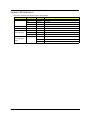
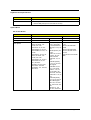
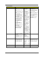
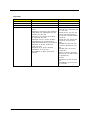
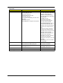
Revision History
Please refer to the table below for the updates made on this service guide.
Date
ii
Chapter
Updates
Copyright
Copyright © 2010 by Acer Incorporated. All rights reserved. No part of this publication may be reproduced,
transmitted, transcribed, stored in a retrieval system, or translated into any language or computer language, in
any form or by any means, electronic, mechanical, magnetic, optical, chemical, manual or otherwise, without
the prior written permission of Acer Incorporated.
iii
Disclaimer
The information in this guide is subject to change without notice.
Acer Incorporated makes no representations or warranties, either expressed or implied, with respect to the
contents hereof and specifically disclaims any warranties of merchantability or fitness for any particular
purpose. Any Acer Incorporated software described in this manual is sold or licensed "as is". Should the
programs prove defective following their purchase, the buyer (and not Acer Incorporated, its distributor, or its
dealer) assumes the entire cost of all necessary servicing, repair, and any incidental or consequential
damages resulting from any defect in the software.
Acer is a registered trademark of Acer Corporation.
Intel is a registered trademark of Intel Corporation.
Pentium Dual-Core, Celeron Dual-Core, Core 2 Duo, Core 2 Quad, Celeron, and combinations thereof, are
trademarks of Intel Corporation.
Other brand and product names are trademarks and/or registered trademarks of their respective holders.
iv
Conventions
The following conventions are used in this manual:
SCREEN
MESSAGES
Denotes actual messages that appear on screen.
NOTE
Gives additional information related to the current topic.
WARNING
Alerts you to any physical risk or system damage that might result from doing
or not doing specific actions.
CAUTION
Gives precautionary measures to avoid possible hardware or software
problems.
IMPORTANT
Reminds you to do specific actions relevant to the accomplishment of
procedures.
v
Service Guide Coverage
This Service Guide provides you with all technical information relating to the BASIC CONFIGURATION
decided for Acer's "global" product offering. To better fit local market requirements and enhance product
competitiveness, your regional office MAY have decided to extend the functionality of a machine (e.g. add-on
card, modem, or extra memory capability). These LOCALIZED FEATURES will NOT be covered in this generic
service guide. In such cases, please contact your regional offices or the responsible personnel/channel to
provide you with further technical details.
FRU Information
Please note WHEN ORDERING FRU PARTS, that you should check the most up-to-date information available
on your regional web or channel. If, for whatever reason, a part number change is made, it will not be noted in
the printed Service Guide. For ACER-AUTHORIZED SERVICE PROVIDERS, your Acer office may have a
DIFFERENT part number code to those given in the FRU list of this printed Service Guide. You MUST use the
list provided by your regional Acer office to order FRU parts for repair and service of customer machines.
vi
Table of Contents
System Tour
Features
System Components
Front Panel
Rear Panel
Internal Components
System LED Indicators
System Utilities
CMOS Setup Utility
Entering CMOS setup
Navigating Through the Setup Utility
Setup Utility Menus
System Disassembly
Disassembly Requirements
Pre-disassembly Procedure
Main Unit Disassembly
Removing the Side Panel
Removing the Front Bezel
Removing the Heatsink Fan Assembly
Removing the Processor
Removing the Optical Drive
Removing the Hard Disk Drive
Removing the Power Supply
Removing the Memory Modules
Removing an Expansion Card
Removing the Front I/O and Card Reader Boards
Removing the Mainboard
Removing the Top Bezel
System Troubleshooting
Hardware Diagnostic Procedure
System Check Procedures
Power System Check
System External Inspection
System Internal Inspection
Checkpoints
Viewing BIOS checkpoints
Bootblock Initialization Code Checkpoints
Bootblock Recovery Code Checkpoints
POST Code Checkpoints
DIM Code Checkpoints
ACPI Runtime Checkpoints
Error Messages
Memory
Boot
Storage Device
Virus Related
System Configuration
CMOS
Miscellaneous
1
1
3
3
5
6
7
9
9
10
10
11
25
25
26
27
29
30
32
34
36
39
40
42
43
46
49
51
53
53
54
54
54
54
55
55
55
56
57
59
59
60
60
60
61
62
63
64
64
vii
USB eModule Error Messages
SMBIOS eModule Error Messages
CPU eModule Error Messages
MPS Table (Multi-processor) eModule Error Messages
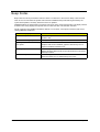
Beep Codes
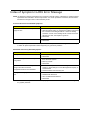
Index of Symptom-to-FRU Error Message
BIOS Recovery
Undetermined Problems
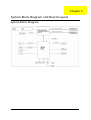
System Block Diagram and Board Layout
System Block Diagram
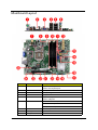
Mainboard Layout
65
65
65
65
66
67
72
74
75
75
76
FRU (Field Replaceable Unit) List
79
Exploded Diagram
X3950 FRU List
X5950 FRU List
80
82
90
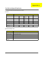
Technical Specifications
viii
93
Chapter 1
System Tour
Features
Below is a brief summary of the computer’s many features:
NOTE: The features listed in this section is for your reference only. The exact configuration of the system
depends on the model purchased.
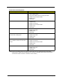
Processor
One LGA 1156 socket
Intel® Core™ i3-530/540 processor
Intel Core i5-650/660/661/670/750 processor
Intel Core i7-860/870 processor
Intel Pentium G6950 processor
Chipset
Intel P55 Express chipset
Memory subsystem
Four DDR3-800/1066/1333 MHz DIMM sockets
Supports single channel or dual-channel memory mode
Maximum of 8GB supported
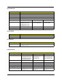
Media storage
Super-Multi DVD drive
BD Combo, BD-ROM, BD-RW drive
SATA hard disk drive
Serial ATA controller
Embedded SATA controllers
Two SATA ports
Audio
Realtek ALC888S-VC HD Audio Codec 7.1
Three audio jacks
Networking
Intel PCI-E Gbe LAN controller PHY
One Gigabit Ethernet LAN port (RJ-45)
PCI I/O
PCI Express x16 bus slot
PCI Express x1 bus slot
Chapter 1
1
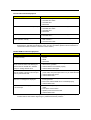
I/O ports
Front
Five USB 2.0 ports
Headphone/speaker-out/line-out jack
Microphone-in jack
9-in-1 media card reader — CompactFlash® (Type I and II), CF+™ Microdrive, MultiMediaCard
(MMC), Reduced-Size MultiMediaCard (RS-MMC), Secure Digital™ (SD) Card, xD-Picture
Card™, Memory Stick™, Memory Stick PRO™
Rear
PS/2 keyboard port
PS/2 mouse port
Three audio jacks
HDMI port
Six USB 2.0 ports
Gigabit LAN port
VGA/monitor port
Operating system and software
Operating system
Windows 7 Home Premium x64
Windows 7 Home Premium X86
Windows 7 Home Basic X86,
FreeDOS
Linux LL95
Applications
Acer eRecovery Management
Acrobat Reader
Acrobat Flash Player
Arcade Deluxe
Cyberlink Power Director
McAfee Internet Security
MyWinLocker
Microsoft Works
Nero 9 Essentials
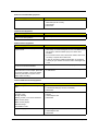
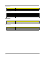
Power supply
220-watts (115/230V AC) PFC or non-PFC power supply
Dimension and weight
2
Dimension (DxWxH)
X3950: 367.8 x 100 x 281.5 mm (with bezel)
X5950: 367.8 x 100 x 281.5 mm (with bezel)
Weight (estimate)
X3950: 8 kg
X5950: 8 kg
Chapter 1
System Components
This section is a virtual tour of the system’s interior and exterior components.
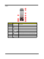
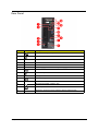
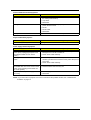
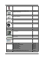
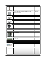
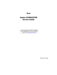
Front Panel
X3950
No.
1
2
Icon
Component
USB 2.0 ports
3
Front I/O cover
4
Microphone-in jack
5
Headphone/Speaker-out/line-out jack
6
CF I/II (CompactFlash Type I/II) slot
7
Media card reader
8
Drive bay door eject button
Press to open drive bay door and access the optical drive.
9
Optical drive bay door
10
HDD activity indicator
11
Power button/power indicator
Chapter 1
3
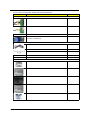
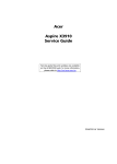
X5950
No.
1
2
4
Icon
Component
USB 2.0 ports
3
Front I/O cover
4
Microphone-in jack
5
Headphone/Speaker-out/line-out jack
6
CF I/II (CompactFlash Type I/II) slot
7
Media card reader
8
Drive bay door eject button
Press to open drive bay door and access the optical drive.
9
Optical drive bay door
10
HDD activity indicator
11
Power button/power indicator
Chapter 1
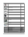
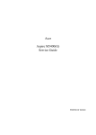
Rear Panel
No.
Icon
Component
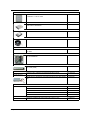
1
Audio in or side speaker jack
2
Gigabit LAN port (10/100/1000 Mbps)
3
Key hole
4
Lock slot
5
Power connector
6
Power supply (Photo shows PFC power supply)
7
PS2 keyboard port
8
PS2 mouse port
9
HDMI
HDMI port
10
VGA/monitor port
11
USB 2.0 ports
12
Microphone/speaker-out/line-in jack
13
Line-out jack
14
Expansion slot (Photo shows graphics card and network card)
Chapter 1
5
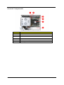
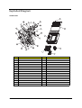
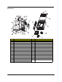
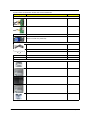
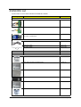
Internal Components
6
No.
Component
1
Optical drive
2
Memory
3
Expansion cards
4
Mainboard
5
Heatsink fan assembly
6
Power supply
Chapter 1
System LED Indicators
This section describes the different system LED indicators.
LED indicator
Color
LED status
Description
Power
Blue
On
S0/S1 state
Blue
Blinking
S3 state
—
Off
S4/S5 state
HDD activity
Blue
Blinking
S0/S1 state
LAN activity
Blue
Blinking
S0/S1 state
LAN port network
speed LED (left)
Amber
On
1000 Mbps link network access
Green
On
100 Mbps link network access
—
Off
10 Mbps link network access
Green
On
Active network link
Blinking
Ongoing network data activity
Off
Off-line network
LAN port network
connection LED
(right)
Chapter 1
7
8
Chapter 1
Chapter 2
System Utilities
CMOS Setup Utility
CMOS setup is a hardware configuration program built into the system ROM, called the complementary metaloxide semiconductor (CMOS) Setup Utility. Since most systems are already properly configured and
optimized, there is no need to run this utility. You will need to run this utility under the following conditions.
When changing the system configuration settings
When redefining the communication ports to prevent any conflicts
When modifying the power management configuration
When changing the password or making other changes to the security setup
When a configuration error is detected by the system and you are prompted ("Run Setup"
message) to make changes to the CMOS setup
NOTE: If you repeatedly receive Run Setup messages, the battery may be bad. In this case, the system
cannot retain configuration values in CMOS. Ask a qualified technician for assistance.
CMOS setup loads the configuration values in a battery-backed nonvolatile memory called CMOS RAM. This
memory area is not part of the system RAM which allows configuration data to be retained when power is
turned off.
Before you run the CMOS Setup Utility, make sure that you have saved all open files. The system reboots
immediately after you close the Setup.
NOTE: CMOS Setup Utility will be simply referred to as “BIOS”, "Setup", or "Setup utility" in this guide.
The screenshots used in this guide display default system values. These values may not be the same
those found in your system.
Chapter 2
9
Entering CMOS setup
1.
Turn on the computer and the monitor.
If the computer is already turned on, close all open applications, then restart the computer.
2.
During POST, press Delete.
If you fail to press Delete before POST is completed, you will need to restart the computer.
The Setup Main menu will be displayed showing the Setup’s menu bar. Use the left and right arrow keys
to move between selections on the menu bar.
Navigating Through the Setup Utility
Use the following keys to move around the Setup utility.
Left and Right arrow keys – Move between selections on the menu bar.
Up and Down arrow keys – Move the cursor to the field you want.
PgUp and PgDn keys – Move the cursor to the previous and next page of a multiple page menu.
Home – Move the cursor to the first page of a multiple page menu.
End – Move the cursor to the last page of a multiple page menu.
+ and - keys – Select a value for the currently selected field (only if it is user-configurable). Press
these keys repeatedly to display each possible entry, or the Enter key to choose from a pop-up
menu.
NOTE: Grayed-out fields are not user-configurable.
Enter key – Display a submenu screen.
NOTE: Availability of submenu screen is indicated by a (>).
10
Esc – If you press this key:
On one of the primary menu screens, the Exit menu displays.
On a submenu screen, the previous screen displays.
When you are making selections from a pop-up menu, closes the pop-up without making a
selection.
F1 – Display the General Help panel.
F9 – Press to load optimized default system values.
F10 – Save changes made the Setup and close the utility.
Chapter 2
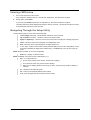
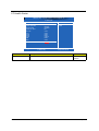
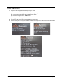
Setup Utility Menus
CMOS Setup Utility - Copyright (c) 1985-2010, American Megatrends, Inc.
► Product Information
► PC Health Status
► Standard CMOS Features
► Frequency/Voltage Control
► Advanced BIOS Features
► Advanced Chipset Features
► BIOS Security Features
Load Default Settings
► Integrated Peripherals
Save & Exit Setup
► Power Management Setup
Exit Without Saving
:Move
Enter:Select
F1:General Help
F10:Save
+/-/:Value
F9:Optimized Defaults
ESC:Exit
v02.66 (C)Copyright 1985-2010, American Megatrends, Inc.
The Setup Main menu includes the following main setup categories.
Product Information
Standard CMOS Features
Advanced BIOS Features
Advanced Chipset Features
Integrated Peripherals
Power Management Setup
PC Health Status
Frequency/Voltage Control
BIOS Security Features
Load Default Settings
Save & Exit Setup
Exit Without Saving
In the descriptive table following each of the menu screenshots, settings in boldface are the default and
suggested settings.
Chapter 2
11
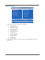
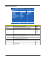
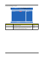
Product Information
The Product Information menu displays basic information about the system. These entries are for your
reference only and are not user-configurable.
CMOS Setup Utility - Copyright (c) 1985-2010, American Megatrends, Inc.
Product Information
Processor Type
Intel (R) Core(TM) i5 CPU
650 @ 3.20GHz
3.20GHz
Processor Speed
2048MB
System Memory
xxxxxxx
Product Name
xxxxxxxxxxxxxxxxxxxxxx
System Serial Number
xxx-xx
System BIOS Version
03/22/2010
BIOS Release Date
Asset Tag Number
:Move
Enter:Select
F1:General Help
+/-/:Value
F10:Save
F9:Optimized Defaults
Parameter
Description
Processor Type
Type of CPU installed on the system.
Processor Speed
Speed of the CPU installed on the system.
System Memory
Total size of system memory installed on the system.
Product Name
Product name of the system.
System Serial Number
Serial number of the system.
System BIOS Version
Version number of the BIOS setup utility.
BIOS Release Date
Date when the BIOS setup utility was released
Asset Tag Number
Asset tag number of this system.
12
Help Item
ESC:Exit
Chapter 2
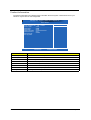
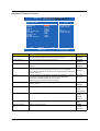
Standard CMOS Features
CMOS Setup Utility - Copyright © 1985-2010, American Megatrends, Inc.
Standard CMOS Features
Help Item
Standard CMOS Features
System Date
System Time
[Fri 01/01/2010]
[21:14:49]
► AHCI Port 1
► AHCI Port 2
[Hard Disk]
[Not Detected]
Halt On
[All, But Keyboard]
:Move
Enter:Select
F1:General Help
+/-/:Value
Use [ENTER] , [TAB]
or [SHIFT-TAB] to
select a field.
Use [+] or [-] to
configure system Date.
F10:Save
F9:Optimized Defaults
ESC:Exit
Parameter
Description
System Date
Set the date following the weekday-month-day-year format.
System Time
(hh:mm:ss)
Set the system time following the hour-minute-second format.
AHCI Port 1/2
Displays the status of auto detection of the AHCI device.
Halt On
Determines whether the system will stop for an error during the POST.
Option
All, But Keyboard
No Errors
All Errors
Chapter 2
13
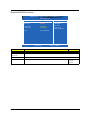
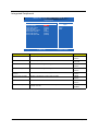
Advanced BIOS Features
CMOS Setup Utility - Copyright © 1985-2010, American Megatrends, Inc.
Advanced BIOS Features
Help Item
Advanced BIOS Features
Quick Boot
Quiet Boot
1st Boot Device
2nd Boot Device
3rd Boot Device
4th Boot Device
► Hard Disk Drive Priority
► Optical Disk Drive Priority
► Removable Device Priority
► Network Device Priority
Bootup Num-Lock
USB Beep Message
:Move
[Enabled]
[Enabled]
[HDD:P0-Hitachi HDT]
[CD/DVD]
[USB: PEN]
[LAN]
[Press Enter]
[Press Enter]
[Press Enter]
[Press Enter]
[On]
[Disabled]
Enter:Select
F1:General Help
+/-/:Value
Allows BIOS to skip
certain tests while
booting. This will
decrease the time
needed to boot the
system.
F10:Save
ESC:Exit
F9:Optimized Defaults
Parameter
Description
Option
Quick Boot
Allows you to decrease the time it takes to boot the computer by shortening
or skipping certain standard booting process.
Enabled
When enabled, the BIOS splash screen displays during startup.
Enabled
Quiet Boot
1st/2nd/3rd/4th Boot Device
Disabled
When disabled, the diagnostic screen displays during startup.
Disabled
Specifies the boot order from the available devices.
Hard Disk
CD/DVD
Removable
Device
LAN
Hard Disk Drive Priority
Press Enter to access the Hard Disk Drive Priority submenu and specify the boot device
priority sequence from available hard drives.
Optical Disk Drive Priority
Press Enter to access the Optical Disk Drive Priority submenu and specify the boot device
priority sequence from available CD/DVD drives.
Removable Device Priority
Press Enter to access the Removable Device Priority submenu and specify the boot device
priority sequence from available removable drives.
Network Device Priority
Press Enter to access the Network Device Priority submenu and specify the boot sequence
from available network devices.
Bootup Num-Lock
Selects power on state for Num Lock.
On
Off
USB Beep Message
14
Enables or disables BIOS to display error beeps or messages during USB
device enumeration.
Enabled
Disabled
Chapter 2
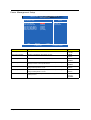
Advanced Chipset Features
CMOS Setup Utility - Copyright © 1985-2010, American Megatrends, Inc.
Advanced Chipset Features
Help Item
Advanced Chipset Features
Intel EIST
Intel Turbo Boost
Intel AES-NI
Intel XD Bit
Intel VT
Memory Hole Remapping
Primary Video
Video Memory Size
DVMT Mode
DVMT/Fixed Memory Size
:Move
[Enabled]
[Enabled]
[Disabled]
[Enabled]
[Enabled]
[Enabled]
[Auto]
[32MB]
[DVMT]
[256MB]
Enter:Select
F1:General Help
Disable:
Disable Enhanced Intel
SpeedStep Technology
Enable:
Enable Enhanced Intel
SpeedStep Technology
+/-/:Value
F10:Save
ESC:Exit
F9:Optimized Defaults
Parameter
Description
Option
Intel EIST
When enabled, this feature allows the OS to reduce power consumption.
Enabled
When disabled, the system operates at maximum CPU speed.
Disabled
Intel Turbo Boost
Enables or disables Intel Turbo Boost Technology.
Enabled
Intel AES-NI
Enables or disables Advanced Encryption Standard New Instructions
(AES-NI).
Enabled
When enabled, the processor disables code execution when a worm attempts
to insert a code in the buffer preventing damage and worm propagation.
Enabled
Disabled
Intel XD Bit
Disabled
Disabled
When disabled, the processor forces the Execute Disable (XD) Bit feature flag
to always return to 0.
Intel VT
Enables or disables the Virtualization Technology (VT) availability. If enabled, a
virtual machine manager (VMM) can utilize the additional hardware
virtualization capabilities provided by this technology.
Enabled
Disabled
Note: A full reset is required to change the setting.
Memory Hole Remapping
Enables or disables remapping of overlapped PCI memory above the total
physical memory.
Enabled
Primary Video
Select a graphic controller as a primary boot device.
Auto
Disabled
PCIE
Onboard VGA
Video Memory Size
Select the amout of system memory used by the Intel graphics device.
32MB
64 MB
128 MB
Disabled
DVMT Mode
Select a video memory mode.
DVMT
Fixed
DVMT/Fixed Memory
Size
Select a video memory size.
256MB
128 MB
Maximum
Chapter 2
15
Integrated Peripherals
CMOS Setup Utility - Copyright © 1985-2010, American Megatrends, Inc.
Integrated Peripherals
Help Item
Integrated Peripherals
Onboard SATA Controller
Onboard SATA Mode
Onboard USB Controller
Legacy USB Support
Onboard Graphics Controller
Onboard Audio Controller
Onboard LAN Controller
Onboard LAN Option ROM
:Move
[Enabled]
[AHCI]
[Enabled]
[Enabled]
[Auto]
[Enabled]
[Enabled]
[Disabled]
Enter:Select
F1:General Help
Options
Disabled
Enabled
+/-/:Value
F10:Save
ESC:Exit
F9:Optimized Defaults
Parameter
Description
Option
Onboard SATA Controller
Select an operating mode for the onboard SATA.
Enabled
Onboard SATA Mode
Select an operating mode for the onboard SATA.
Disabled
AHCI
Native IDE
Onboard USB Controller
Enables or disables support for legacy USB devices
Legacy USB Support
Enables or disables support for legacy USB devices.
Enabled
Disabled
Enabled
Disabled
Onboard Graphics
Controller
Enables or disables the onboard graphics controller.
Auto
Onboard Audio Controller
Enables or disables the onboard audio controller.
Enabled
Onboard
Disabled
Onboard LAN Controller
Enables or disables the onboard LAN controller.
Onboard LAN Option ROM
Enables or disables the load of embedded option ROM for onboard
network controller.
Enabled
Disabled
16
Enabled
Disabled
Chapter 2
Power Management Setup
CMOS Setup Utility - Copyright © 1985-2010, American Megatrends, Inc.
Power Management Setup
Help Item
Power Management Setup
ACPI Suspend Mode
Deep Power Off Mode
Power On by RTC Alarm
Power On by PCIE Devices
Wake Up by PS/2 KB/Mouse
Wake Up by USB KB/Mouse
Restore On AC Power Loss
:Move
[S3 (STR)]
[Enabled]
[Disabled]
[Disabled]
[Enabled]
[Enabled]
[Last State]
Enter:Select
F1:General Help
Select the ACPI
state used for
System Suspend.
+/-/:Value
F10:Save
ESC:Exit
F9:Optimized Defaults
Parameter
Description
Option
ACPI Suspend Mode
Select an ACPI state.
S3 (STR)
S1 (POS)
Deep Power Off Mode
Enables or disables the deep power off mode.
Enabled
Power On by RTC Alarm
Enables or disables real time clock (RTC) to generate a wake event.
Enabled
Disabled
Disabled
Power On by PCIE Devices
Enables or disables to wake up the system from a power saving mode
through an event on PCI Express device.
Enabled
Wake Up by PS/2 KB/Mouse
Enables or disables to wake up the system from a power saving mode
using a PS2 keyboard or mouse.
Enabled
Wake Up by USB KB/Mouse
Enables or disables to wake up the system from a power saving mode
using a USB keyboard or mouse.
Enabled
Restore On AC Power Loss
Enables or disables the system to reboot after a power failure or
interrupt occurs.
Power Off
Disabled
Disabled
Disabled
Power On
Last State
Chapter 2
17
PC Health Status
CMOS Setup Utility - Copyright © 1985-2010, American Megatrends, Inc.
PC Health Status
Help Item
PC Health Status
CPU Temperature (PECI Mode)
System Temperature
CPU Fan Speed
System Fan Speed
:23
o
o
:44 C/111 F
:1015 RPM
:N/A
CPU Core
+1.1V
+3.30V
+5.00V
+12.0V
5VSB
VBAT
:1.176 V
:1.116 V
:3.346 V
:5.040 V
:11.808 V
:5.040 V
:3.336 V
Smart Fan
[Enabled]
:Move
Enter:Select
F1:General Help
Disabled
Enabled
+/-/:Value
F10:Save
ESC:Exit
F9:Optimized Defaults
Parameter
Description
Option
Smart Fan
Enables or disables the smart system fan control function.
Enabled
Disabled
18
Chapter 2
Frequency/Voltage Control
CMOS Setup Utility - Copyright © 1985-2010, American Megatrends, Inc.
Frequency/Voltage Control
Help Item
Frequency/Voltage Control
Clock to All DIMM/PCI/PCIE
Spread Spectrum
:Move
[Enabled]
[Enabled]
Enter:Select
F1:General Help
Enable Clock to All
DIMM/PCI/PCIE.
+/-/:Value
F10:Save
ESC:Exit
F9:Optimized Defaults
Parameter
Description
Option
Clock to All DIMM/PCI/PCIE
Enables or disables the system to detect the DIMM/PCI/PCIE clock
automatically during bootup.
Enabled
Spread Spectrum
Enables or disables the reduction of the mainboard’s EMI.
Enabled
Note: Remember to disable the Spread Spectrum feature if you are
overclocking. A slight jitter can introduce a temporary boost in clock
speed causing the overclocked processor to lock up.
Disabled
Chapter 2
Disabled
19
BIOS Security Features
CMOS Setup Utility - Copyright © 1985-2010, American Megatrends, Inc.
BIOS Security Features
Help Item
BIOS Security Features
Install or Change the
password.
Supervisor Password :Not Installed
User Password
:Not Installed
Change Supervisor Password
:Move
[Press Enter]
Enter:Select
F1:General Help
+/-/:Value
F10:Save
F9:Optimized Defaults
ESC:Exit
Parameter
Description
Supervisor Password
Indicates the status of the supervisor password.
User Password
Indicates the status of the user password.
Change Supervisor
Password
Supervisor password prevents unauthorized access to the BIOS Setup Utility.
Press Enter to change the Supervisor password.
Setting a system password
1.
Use the up/down arrow keys to select a password parameter (Change Supervisor Password) menu then
press Enter.
A password box will appear.
2.
Type a password then press Enter.
The password may consist up to six alphanumeric characters (A-Z, a-z, 0-9)
3.
Retype the password to verify the first entry then press Enter again.
4.
Press F10.
5.
Select Yes to save the new password and close the Setup Utility.
Changing the system password
20
1.
Use the up/down arrow keys to select password parameter (Change Supervisor Password) menu then
press Enter.
2.
Type the original password then press Enter.
3.
Type a new password then press Enter.
4.
Retype the password to verify the first entry then press Enter again.
5.
Press F10.
6.
Select Yes to save the new password and close the Setup Utility.
Chapter 2
Removing a system password
1.
Use the up/down arrow keys to select password parameter (Change Supervisor Password) menu then
press Enter.
2.
Enter the current password then press Enter.
3.
Press Enter twice without entering anything in the password fields.
Chapter 2
21
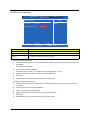
Load Default Settings
The Load Default Settings menu allows you to load the default settings for all BIOS setup parameters. Setup
defaults are quite demanding in terms of resources consumption. If you are using low-speed memory chips or
other kinds of low-performance components and you choose to load these settings, the system might not
function properly.
CMOS Setup Utility - Copyright © 1985-2010, American Megatrends, Inc.
► Product Information
► PC Health Status
► Standard CMOS Features
► Frequency/Voltage Control
► Advanced BIOS Features
► BIOS Security Features
► Advanced Chipset Features
► Integrated Peripherals
Load Default Settings
Load Optimal Defaults?
Save & Exit Setup
► Power Management Setup
[OK]
:Move
Enter:Select
F1:General Help
Exit Without Saving
[Cancel]
F10:Save
+/-/:Value
F9:Optimized Defaults
ESC:Exit
Load Optimal Default values for all the setup questions.
v02.66 (C)Copyright 1985-2010, American Megatrends, Inc.
22
Chapter 2
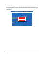
Save & Exit Setup
The Save & Exit Setup menu allows you to save changes made and close the Setup Utility.
CMOS Setup Utility - Copyright © 1985-2010, American Megatrends, Inc.
► Product Information
► PC Health Status
► Standard CMOS Features
► Frequency/Voltage Control
► Advanced BIOS Features
► Advanced Chipset Features
► BIOS Security Features
Load Default Settings
► Integrated Peripherals
Save configuration changes
and& exit
Save
Exitsetup?
Setup
► Power Management Setup
Exit Without Saving
[OK]
[Cancel]
:Move
Enter:Select
F1:General Help
+/-/:Value
F10:Save
F9:Optimized Defaults
ESC:Exit
Exit system setup with saving the changes.
v02.66 (C)Copyright 1985-2010, American Megatrends, Inc.
Chapter 2
23
Exit Without Saving
The Exit Without Saving menu allows you to discard changes made and close the Setup Utility.
CMOS Setup Utility - Copyright © 1985-2010, American Megatrends, Inc.
► Product Information
► PC Health Status
► Standard CMOS Features
► Frequency/Voltage Control
► Advanced BIOS Features
► Advanced Chipset Features
► BIOS Security Features
Load Default Settings
► Integrated Peripherals
Discard changes andSave
exit &setup?
Exit Setup
► Power Management Setup
Exit Without Saving
[OK]
[Cancel]
:Move
Enter:Select
F1:General Help
+/-/:Value
F10:Save
F9:Optimized Defaults
ESC:Exit
Exit system setup without saving the changes.
v02.66 (C)Copyright 1985-2010, American Megatrends, Inc.
24
Chapter 2
Chapter 3
System Disassembly
This chapter contains step-by-step procedures on how to disassemble the desktop computer for maintenance
and troubleshooting.
Disassembly Requirements
To disassemble the computer, you need the following tools:
Wrist grounding strap and conductive mat for preventing electrostatic discharge
Flat-blade screwdriver
Philips screwdriver
Hex screwdriver
Plastic flat-blade screwdriver
Plastic tweezers
NOTE: The screws for the different components vary in size. During the disassembly process, group the
screws with the corresponding components to avoid mismatch when putting back the components.
Chapter 3
25
Pre-disassembly Procedure
Before proceeding with the disassembly procedure, perform the steps listed below:
26
1.
Turn off the system and all the peripherals connected to it.
2.
Unplug the power cord from the power outlets.
3.
Unplug the power cord from the system.
4.
Unplug all peripheral cables from the system.
5.
Place the system unit on a flat, stable surface.
Chapter 3
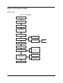
Main Unit Disassembly
X3950 model
MAIN UNIT DISASSEMBLY
MAIN UNIT
Ax2
SIDE PANEL
FRONT BEZEL
HEATSINK FAN
ASSEMBLY
PROCESSOR
Bx2
Cx2
HDD-ODD BRACKET
OPTICAL DISK
DRIVE
Dx4
HDD MODULE
HDD
Ax3, Bx1
POWER SUPPLY
MEMORY MODULES
PCI CARD
Ax1
TV TUNER CARD
or
NETWORK CARD
or
GRAPHICS CARD
Bx2
Bx1
FRONT I/O AND
CARD READER BOARD
BRACKET
FRONT I/O BOARD
Bx2
CARD READER
BOARD
Bx6
MAINBOARD
Chapter 3
27
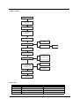
X5950 model
MAIN UNIT DISASSEMBLY
MAIN UNIT
Ax2
SIDE PANEL
FRONT BEZEL
HEATSINK FAN
ASSEMBLY
PROCESSOR
Bx2
Cx2
HDD-ODD BRACKET
OPTICAL DISK
DRIVE
Dx4
HDD
HDD MODULE
Ax3, Bx1
POWER SUPPLY
MEMORY MODULES
PCI CARD
Ax1
TV TUNER CARD
or
NETWORK CARD
or
GRAPHICS CARD
Bx2
Bx1
FRONT I/O AND
CARD READER BOARD
BRACKET
FRONT I/O BOARD
Bx2
CARD READER
BOARD
Bx6
MAINBOARD
TOP BEZEL
Screw List
28
Code
Screw
Part No.
A
#6-32 L5 BZN
86.00J07.B60
B
#6-32 L6 NI
86.00J44.C60
C
M3xL5 BZN
86.1A324.5R0
D
#6-32*3/16 NI
86.5A5B6.012
Chapter 3
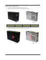
Removing the Side Panel
1.
Perform the pre-disassembly procedure described on page 26.
2.
Remove the two screws (A) located on the rear edge of the side panel.
X5950
X3950
Screw (Quantity)
Color
Torque
Part No.
#6-32 L5 BZN (2)
Black
5.5 to 6.5 kgf-cm
86.00J07.B60
3.
Slide the panel toward the back of the unit until the tabs on the cover disengage with the slots on the unit.
4.
Lift the panel away from the unit and put it aside for reinstallation later.
X3950
Chapter 3
X5950
29
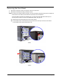
Removing the Front Bezel
1.
Remove the side panel. Refer to the previous section for instructions.
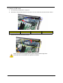
2. Remove the front bezel according to machine model.
NOTE: To remove the X3950 model’s front bezel, you must first release the tabs securing the front bezel and
disconnect the LED cable, located under the front bezel, from the mainboard.
If the LED cable is secured in the retaining clip, you must remove the HDD-ODD bracket prior to
removing the front bezel. To remove the HDD-ODD bracket, see page 36.
(1). Release the front bezel retention tabs from the unit interior.
(2). For the X3950 model, rotate the bezel, then proceed to the next step to remove the front bezel.
For the X5950 model, pull the bezel off the unit.
X3950
X5950
30
Chapter 3
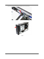
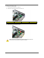
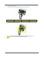
(3). Disconnect the LED cable from the mainboard, then remove the bezel.
X3950
Chapter 3
31
Removing the Heatsink Fan Assembly
WARNING: The heatsink becomes very hot when the system is on. NEVER touch the heatsink with any metal
or with your hands.
1.
See “Removing the Side Panel” on page 29.
2.
Use a long-nosed screwdriver to loosen the four screws on the heatsink fan assembly.
3.
Lift the heatsink fan assembly off the mainboard.
X3950
32
X5950
Chapter 3
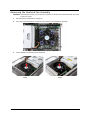
4.
Lay it down in an upright position—with the thermal patch facing upward, on top of the optical drive then
disconnect the heatsink fan cable from its mainboard connector. Do not let the thermal patch on the
heatsink fan assembly touch the work surface.
X3950
5.
X5950
Use an alcohol pad to wipe off the thermal grease from both the heatsink and the processor.
Chapter 3
33
Removing the Processor
IMPORTANT:Before removing a processor from the mainboard, make sure to create a backup file of all
important data.
WARNING:The processor becomes very hot when the system is on. Allow it to cool off first before handling.
34
1.
See “Removing the Side Panel” on page 29.
2.
See “Removing the Heatsink Fan Assembly” on page 32.
3.
Press the load lever, then move it to the right to release the load lever from the retention tab.
4.
Pull the load lever to the fully open, upright position.
Chapter 3
5.
Open the load plate, then pull out the processor from the socket.
IMPORTANT:If you are going to install a new processor, note the arrow on the corner, highlighted with a circle
in the photo above, to make sure the processor is properly oriented over the socket.
Chapter 3
35
Removing the Optical Drive
1.
See “Removing the Side Panel” on page 29.
2.
See “Removing the Front Bezel” on page 30.
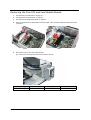
3.
Remove the HDD-ODD bracket.
(1). Disconnect the data and power cables from their optical drive connectors.
(2). Remove the two screws (B) that secure the HDD-ODD bracket.
X3950
36
X5950
Screw (Quantity)
Color
Torque
Part No.
6-32 xL6 (2)
Silver
5.7 to 6.3 kgf-cm
86.00J44.C60
Chapter 3
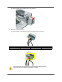
(3). Lift the HDD-ODD bracket, then disconnect the data and power cables from their HDD connector.
X3950
X5950
(4). If necessary, open the cable retention clips that secure the data cable, then disconnect the cables
from their mainboard connectors.
X3950
4.
X5950
Remove the two screws (C) that secure the optical drive.
Screw (Quantity)
Color
Torque
Part No.
M3xL5 BZN (2)
Black
5.5 to 6.5 kgf-cm
86.1A324.5R0
Chapter 3
37
5.
38
Slide the optical drive out of the bracket.
Chapter 3
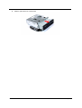
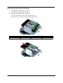
Removing the Hard Disk Drive
1.
See “Removing the Side Panel” on page 29.
2.
See “Removing the Front Bezel” on page 30.
3.
Remove the HDD-ODD bracket. See page 36.
(1). Place the bracket on a clean, static-free work surface.
(2). Remove the four screws (D) that secure the HDD module.
Screw (Quantity)
Color
Torque
Part No.
#6-32*3/16 NI (4)
Silver
5.7 to 6.3 kgf-cm
86.5A5B6.012
(3). Slide the HDD out of the bracket.
Chapter 3
39
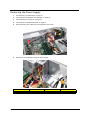
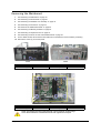
Removing the Power Supply
40
1.
See “Removing the Side Panel” on page 29.
2.
See “Removing the Heatsink Fan Assembly” on page 32.
3.
See “Removing the Processor” on page 34.
4.
See “Remove the HDD-ODD bracket” on page 36.
5.
Disconnect the power cables from their mainboard connectors.
6.
Remove the screw (B) that secures the power supply .
Screw (Quantity)
Color
Torque
Part No.
#6-32 L6 NI (1)
Silver
5.7 to 6.3 kgf-cm
86.00J44.C60
Chapter 3
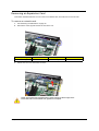
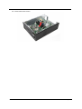
7.
Remove the three screws (A) that secure the power supply module.
X3950
8.
X5950
Screw (Quantity)
Color
Torque
Part No.
#6-32 L5 BZN (3)
Black
5.5 to 6.5 kgf-cm
86.00J07.B60
Lift the power supply module off the unit.
X3950
Chapter 3
X5950
41
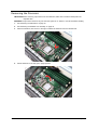
Removing the Memory Modules
IMPORTANT:Before removing any DIMM, make sure to create a backup file of all important data.
1.
See “Removing the Side Panel” on page 29.
2.
See “Removing the Front Bezel” on page 30.
3.
See “Remove the HDD-ODD bracket” on page 36.
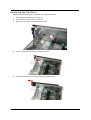
4.
Press the holding clips on both sides of the DIMM slot outward to release the DIMM.
5.
Gently pull the DIMM upward to remove it from its slot.
NOTE: The DIMM has been highlighted with a yellow rectangle as above image shows.
Please detach the DIMM and follow local regulations for disposal.
(4). Do the same to remove the other modules.
42
Chapter 3
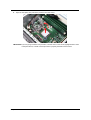
Removing an Expansion Card
This section includes instruction on how to remove a network card, VGA card, and a TV tuner card.
To remove a network card:
1.
See “Removing the Side Panel” on page 29.
2.
Remove the screw (A) that secures the card to the unit.
3.
Screw (Quantity)
Color
Torque
Part No.
#6-32 L5 BZN (1)
Black
5.7 to 6.3 kgf-cm
86.00J07.B60
Pull the card out of its mainboard connector.
NOTE: The card has been highlighted with a yellow rectangle as above image shows.
Please detach the card and follow local regulations for disposal.
Chapter 3
43
To remove a VGA card:
1.
See “Removing the Side Panel” on page 29.
2.
Remove the screw (A) that secures the card to the unit, then press down the securing tab on the slot.
3.
Screw (Quantity)
Color
Torque
Part No.
#6-32 L5 BZN (1)
Black
5.7 to 6.3 kgf-cm
86.00J07.B60
Pull the card out of its mainboard connector.
NOTE: The card has been highlighted with a yellow rectangle as above image shows.
Please detach the card and follow local regulations for disposal.
44
Chapter 3
To remove a TV tuner card:
1.
See “Removing the Side Panel” on page 29.
2.
Remove the screw (A) that secures the card to the unit.
3.
Screw (Quantity)
Color
Torque
Part No.
#6-32 L5 BZN (1)
Black
5.7 to 6.3 kgf-cm
86.00J07.B60
Pull the card out of its mainboard connector.
NOTE: The card has been highlighted with a yellow rectangle as above image shows.
Please detach the card and follow local regulations for disposal.
Chapter 3
45
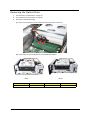
Removing the Front I/O and Card Reader Boards
1.
See “Removing the Side Panel” on page 29.
2.
See “Removing the Front Bezel” on page 30.
3.
See “Remove the HDD-ODD bracket” on page 36.
4.
Open the cable retention clips and disconnect the USB, 1394, and audio cables from their mainboard
connectors.
X3950
5.
X5950
Remove the front I/O and card reader bracket.
(1). Remove the screw (B) that secures the bracket to the unit.
46
Screw (Quantity)
Color
Torque
Part No.
#6-32 L6 NI (1)
Silver
4.75 to 5.2 kgf-cm
86.00J44.C60
Chapter 3
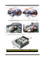
(2). Pull the bracket with the cables out of the unit, as shown.
6.
Remove the card reader board.
(1). Remove the two screws (B) that secure the card reader board to the bracket.
Screw (Quantity)
Color
Torque
Part No.
#6-32 L6 NI (2)
Silver
3.5 to 4.5 kgf-cm
86.00J44.C60
(2). Pull the board out of the bracket.
NOTE: The card has been highlighted with a yellow rectangle as above image shows.
Please detach the card and follow local regulations for disposal.
Chapter 3
47
7.
Remove the front I/O board.
(1). Remove the two screws (B) that secure the I/O board to the bracket.
Screw (Quantity)
Color
Torque
Part No.
#6-32 L6 NI (2)
Silver
3.8 to 4.2 kgf-cm
86.00J44.C60
(2). Pull the I/O board out of the bracket.
NOTE: The card has been highlighted with a yellow rectangle as above image shows.
Please detach the card and follow local regulations for disposal.
48
Chapter 3
Removing the Mainboard
1.
See “Removing the Side Panel” on page 29.
2.
See “Removing the Front Bezel” on page 30.
3.
See “Removing the Heatsink Fan Assembly” on page 32.
4.
See “Removing the Processor” on page 34.
5.
See “Remove the HDD-ODD bracket” on page 36.
6.
See “Removing the Memory Modules” on page 42.
7.
See “Removing an Expansion Card” on page 43.
8.
See “Removing the Front I/O and Card Reader Boards” on page 46.
9.
For the X5950 model, disconnect the LED cable from its mainboard connector before proceeding.
10. Remove the screw (C) on the rear panel.
X3950
X5950
Screw (Quantity)
Color
Torque
Part No.
M3xL5 BZN (1)
Black
5.5 to 6.5 kgf-cm
86.1A324.5R0
11. Remove the six screws (B) that secure the mainboard to the housing.
Screw (Quantity)
Color
Torque
Part No.
#6-32 L6 NI (6)
Silver
5.7 to 6.3 kgf-cm
86.00J44.C60
NOTE: The mainboard has been highlighted with a yellow rectangle as above image
shows. Please detach the mainboard and follow local regulations for disposal.
Chapter 3
49
12. Lift the board off the housing.
50
Chapter 3
Removing the Top Bezel
NOTE: The following instruction is applicable only to the X5950 model.
1.
See “Removing the Side Panel” on page 29.
2.
See “Removing the Front Bezel” on page 30.
3.
Detach the LED cable from its mainboard connector.
4.
Insert the cable into the hole on the housing, as shown.
5.
Slide the bezel toward the front, then lift the bezel off the housing.
Chapter 3
51
52
Chapter 3
Chapter 4
System Troubleshooting
This chapter provides instructions on how to troubleshoot system hardware problems.
Hardware Diagnostic Procedure
IMPORTANT:The diagnostic tests described in this chapter are only intended to test Acer products. Non-Acer
products, prototype cards, or modified options can give false errors and invalid system
responses.
1.
Obtain the failing symptoms in as much detail as possible.
2.
Verify the symptoms by attempting to recreate the failure by running the diagnostic tests or repeating the
same operation.
3.
Refer to the following sections to determine which corrective action to perform.
Chapter 4
System Check Procedures
Checkpoints
Error Messages
Undetermined Problems
53
System Check Procedures
Power System Check
If the system will power on, skip this section. Refer to System External Inspection.
If the system will not power on, do the following:
Check if the power cable is properly connected to the system and AC source.
Check if the voltage selector switch is set to the correct voltage setting.
System External Inspection
1.
Inspect the LED indicators on the front panel, which can indicate the malfunction. For the LED locations
and description of their behaviour, see “System LED Indicators” on page 7.
2.
Make sure that air flow is not blocked.
3.
Make sure nothing in the system is making contact that could short out power.
4.
If the problem is not evident, continue with System Internal Inspection.
System Internal Inspection
1.
Turn off the system and all the peripherals connected to it.
2.
Unplug the power cord from the power outlets.
3.
Unplug the power cord from the system.
4.
Unplug all peripheral cables from the system.
5.
Place the system unit on a flat, stable surface.
6.
Remove the system covers. For instructions on removing system covers, refer to “System Disassembly”
on page 25.
7.
Verify that components are properly seated.
8.
Verify that all cable connectors inside the system are firmly and correctly attached to their appropriate
connectors.
9.
Verify that all components are Acer-qualified and supported.
10. Replace the system covers.
11. Power on the system.
12. If the problem with the system is not evident, you can try viewing the POST messages and BIOS event
logs during the system startup.
54
Chapter 4
Checkpoints
A checkpoint is either a byte or word value output to I/O port 80h. The BIOS outputs checkpoints throughout
bootblock and Power-On Self Test (POST) to indicate the task the system is currently executing. Checkpoints
are very useful in aiding software developers or technicians in debugging problems that occur during the preboot process.
Viewing BIOS checkpoints
Viewing all checkpoints generated by the BIOS requires a checkpoint card, also referred to as a POST card or
POST diagnostic card. These are ISA or PCI add-in cards that show the value of I/O port 80h on a LED
display. Checkpoints may appear on the bottom right corner of the screen during POST. This display method is
limited, since it only displays checkpoints that occur after the video card has been activated.
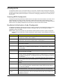
Bootblock Initialization Code Checkpoints
The Bootblock initialization code sets up the chipset, memory, and other components before system memory
is available. The following table describes the type of checkpoints that may occur during the bootblock
initialization portion of the BIOS.
NOTE: Please note that checkpoints may differ between different platforms based on system configuration.
Checkpoints may change due to vendor requirements, system chipset or option ROMs from add-in PCI
devices.
Checkpoint
Description
Before D1
Early chipset initialization is done. Early super I/O initialization is done including RTC
and keyboard controller. NMI is disabled.
D1
Perform keyboard controller BAT test. Check if waking up from power management
suspend state. Save power-on CPUID value in scratch CMOS.
D0
Go to flat mode with 4GB limit and GA20 enabled. Verify the bootblock checksum.
D2
Disable CACHE before memory detection. Execute full memory sizing module. Verify
that flat mode is enabled.
D3
If memory sizing module not executed, start memory refresh and do memory sizing in
Bootblock code. Do additional chipset initialization. Re-enable CACHE. Verify that flat
mode is enabled.
D4
Test base 512KB memory. Adjust policies and cache first 8MB. Set stack.
D5
Bootblock code is copied from ROM to lower system memory and control is given to it.
BIOS now executes out of RAM.
D6
Both key sequence and OEM specific method is checked to determine if “BIOS
Recovery” is forced. Main BIOS checksum is tested. If “BIOS Recovery” is necessary,
control flows to checkpoint E0. See Bootblock Recovery Code Checkpoints section for
more information.
D7
Restore CPUID value back into register. The Bootblock-Runtime interface module is
moved to system memory and control is given to it. Determine whether to execute
serial flash.
D8
The Runtime module is uncompressed into memory. CPUID information is stored in
memory.
D9
Store the Uncompressed pointer for future use in PMM. Copying Main BIOS into
memory. Leaves all RAM below 1MB Read-Write including E000 and F000 shadow
areas but closing SMRAM.
DA
Restore CPUID value back into register. Give control to BIOS POST
(ExecutePOSTKernel). See POST Code Checkpoints section for more information.
E1-E8
EC-EE
OEM memory detection/configuration error. This range is reserved for chipset vendors
and system manufacturers. The error associated with this value may be different from
one platform to the next.
Chapter 4
55
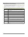
Bootblock Recovery Code Checkpoints
The Bootblock recovery code gets control when the BIOS determines that a “BIOS Recovery” needs to occur
because the user has forced the update or the BIOS checksum is corrupt. Refer to “BIOS Recovery” on page
72 for more information about performing a “BIOS Recovery” .
The following table describes the type of checkpoints that may occur during the Bootblock recovery portion of
the BIOS.
NOTE: Checkpoints may differ between different platforms based on system configuration. Checkpoints may
change due to vendor requirements, system chipset or option ROMs from add-in PCI devices.
Checkpoint
56
Description
E0
Initialize the floppy controller in the super I/O. Some interrupt vectors are
initialized. DMA controller is initialized. 8259 interrupt controller is initialized.
L1 cache is enabled.
E9
Set up floppy controller and data. Attempt to read from floppy.
EA
Enable ATAPI hardware. Attempt to read from ARMD and ATAPI CDROM.
EB
Disable ATAPI hardware. Jump back to checkpoint E9.
EF
Read error occurred on media. Jump back to checkpoint EB.
F0
Search for pre-defined recovery file name in root directory.
F1
Recovery file not found.
F2
Start reading FAT table and analyze FAT to find the clusters occupied by the recovery
file.
F3
Start reading the recovery file cluster by cluster.
F5
Disable L1 cache.
FA
Check the validity of the recovery file configuration to the current configuration of the
flash part.
FB
Make flash write enabled through chipset and OEM specific method. Detect proper
flash part. Verify that the found flash part size equals the recovery file size.
F4
The recovery file size does not equal the found flash part size.
FC
Erase the flash part.
FD
Program the flash part.
FF
The flash has been updated successfully. Make flash write disabled. Disable ATAPI
hardware. Restore CPUID value back into register. Give control to F000 ROM at
F000:FFF0h.
Chapter 4
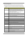
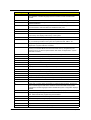
POST Code Checkpoints
The POST code checkpoints are the largest set of checkpoints during the BIOS preboot process. The
following table describes the type of checkpoints that may occur during the POST portion of the BIOS.
NOTE: Please note that checkpoints may differ between different platforms based on system configuration.
Checkpoints may change due to vendor requirements, system chipset or option ROMs from add-in PCI
devices.
Checkpoint
Description
03
Disable NMI, Parity, video for EGA, and DMA controllers. Initialize BIOS, POST,
Runtime data area. Also initialize BIOS modules on POST entry and GPNV area.
Initialized CMOS as mentioned in the Kernel Variable "wCMOSFlags."
04
Check CMOS diagnostic byte to determine if battery power is OK and CMOS
checksum is OK. Verify CMOS checksum manually by reading storage area.
If the CMOS checksum is bad, update CMOS with power-on default values and
clear passwords. Initialize status register A.
Initializes data variables that are based on CMOS setup questions.
Initializes both the 8259 compatible PICs in the system
05
Initializes the interrupt controlling hardware (generally PIC) and interrupt vector
table.
06
Do R/W test to CH-2 count reg. Initialize CH-0 as system timer.Install the
POSTINT1Ch handler. Enable IRQ-0 in PIC for system timer interrupt. Traps
INT1Ch vector to "POSTINT1ChHandlerBlock."
07
Fixes CPU POST interface calling pointer.
08
Initializes the CPU. The BAT test is being done on KBC. Program the keyboard
controller command byte is being done after Auto detection of KB/MS using AMI
KB-5.
C0
Early CPU Init Start -- Disable Cache – Init Local APIC
C1
Set up boot strap processor Information
C2
Set up boot strap processor for POST
C5
Enumerate and set up application processors
C6
Re-enable cache for boot strap processor
C7
Early CPU Init Exit
0A
Initializes the 8042 compatible Key Board Controller.
0B
Detects the presence of PS/2 mouse.
0C
Detects the presence of Keyboard in KBC port.
0E
Testing and initialization of different Input Devices. Also, update the Kernel
Variables.
Traps the INT09h vector, so that the POST INT09h handler gets control for IRQ1.
Uncompress all available language, BIOS logo, and Silent logo modules.
13
Early POST initialization of chipset registers.
24
Uncompress and initialize any platform specific BIOS modules. GPNV is initialized
at this checkpoint.
30
Initialize System Management Interrupt.
2A
Initializes different devices through DIM.
See DIM Code Checkpoints section for more information.
2C
Initializes different devices. Detects and initializes the video adapter installed in the
system that have optional ROMs.
2E
Initializes all the output devices.
Chapter 4
57
Checkpoint
31
58
Description
Allocate memory for ADM module and uncompress it. Give control to ADM module
for initialization. Initialize language and font modules for ADM. Activate ADM
module.
33
Initializes the silent boot module. Set the window for displaying text information.
37
Displaying sign-on message, CPU information, setup key message, and any OEM
specific information.
38
Initializes different devices through DIM. See DIM Code Checkpoints section for
more information. USB controllers are initialized at this point.
39
Initializes DMAC-1 & DMAC-2.
3A
Initialize RTC date/time.
3B
Test for total memory installed in the system. Also, Check for DEL or ESC keys to
limit memory test. Display total memory in the system.
3C
Mid POST initialization of chipset registers.
40
Detect different devices (Parallel ports, serial ports, and coprocessor in CPU, ...
etc.) successfully installed in the system and update the BDA, EBDA…etc.
50
Programming the memory hole or any kind of implementation that needs an
adjustment in system RAM size if needed.
52
Updates CMOS memory size from memory found in memory test. Allocates
memory for Extended BIOS Data Area from base memory. Programming the
memory hole or any kind of implementation that needs an adjustment in system
RAM size if needed.
60
Initializes NUM-LOCK status and programs the KBD typematic rate.
75
Initialize Int-13 and prepare for IPL detection.
78
Initializes IPL devices controlled by BIOS and option ROMs.
7A
Initializes remaining option ROMs.
7C
Generate and write contents of ESCD in NVRam.
84
Log errors encountered during POST.
85
Display errors to the user and gets the user response for error.
87
Execute BIOS setup if needed / requested. Check boot password if installed.
8C
Late POST initialization of chipset registers.
8D
Build ACPI tables (if ACPI is supported)
8E
Program the peripheral parameters. Enable/Disable NMI as selected.
90
Late POST initialization of system management interrupt.
A0
Check boot password if installed.
A1
Clean-up work needed before booting to OS.
A2
Takes care of runtime image preparation for different BIOS modules. Fill the free
area in F000h segment with 0FFh. Initializes the Microsoft IRQ Routing Table.
Prepares the runtime language module. Disables the system configuration display if
needed.
A4
Initialize runtime language module. Display boot option popup menu.
A7
Displays the system configuration screen if enabled. Initialize the CPU’s before
boot, which includes the programming of the MTRR’s.
A8
Prepare CPU for OS boot including final MTRR values.
A9
Wait for user input at config display if needed.
AA
Uninstall POST INT1Ch vector and INT09h vector. Deinitializes the ADM module.
AB
Prepare BBS for Int 19 boot.
AC
End of POST initialization of chipset registers.
Chapter 4
Checkpoint
Description
B1
Save system context for ACPI.
00
Passes control to OS Loader (typically INT19h).
61-70
OEM POST Error. This range is reserved for chipset vendors and system
manufacturers. The error associated with this value may be different from one
platform to the next.
DIM Code Checkpoints
The Device Initialization Manager (DIM) gets control at various times during BIOS POST to initialize different
system busses. The following table describes the main checkpoints where the DIM module is accessed.
NOTE: Checkpoints may differ between different platforms based on system configuration. Checkpoints may
change due to vendor requirements, system chipset or option ROMs from add-in PCI devices.
Checkpoint
Description
2A
Initialize different buses and perform the following functions: Reset, Detect, and
Disable (function 0); Static Device Initialization (function 1); Boot Output Device
Initialization (function 2). Function 0 disables all device nodes, PCI devices, and PnP
ISA cards. It also assigns PCI bus numbers. Function 1 initializes all static devices
that include manual configured onboard peripherals, memory and I/O decode windows
in PCI-PCI bridges, and noncompliant PCI devices. Static resources are also
reserved. Function 2 searches for and initializes any PnP, PCI, or AGP video devices.
38
Initialize different buses and perform the following functions: Boot Input Device
Initialization (function 3); IPL Device Initialization (function 4); General Device
Initialization (function 5). Function 3 searches for and configures PCI input devices
and detects if system has standard keyboard controller. Function 4 searches for and
configures all PnP and PCI boot devices. Function 5 configures all onboard
peripherals that are set to an automatic configuration and configures all remaining
PnP and PCI devices.
ACPI Runtime Checkpoints
Checkpoint
Description
AC
First ASL check point. Indicates the system is running in ACPI mode.
AA
System is running in APIC mode
01, 02, 03, 04, 05
Entering sleep state S1, S2, S3, S4, or S5.
10, 20, 30, 40, 50
Waking from sleep state S1, S2, S3, S4, or S5
Chapter 4
59
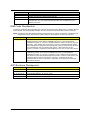
Error Messages
The following tables describes the error messages that may appear during POST. Each message is listed with
a detailed description of the error.
Memory
Message Displayed
Description
Gate20 Error
The BIOS is unable to properly control the mainboard’s Gate A20 function, which
controls access of memory over 1 MB. This may indicate a problem with the
mainboard.
Multi-Bit ECC Error
This message will only occur on systems using ECC enabled memory modules.
ECC memory has the ability to correct single-bit errors that may occur from faulty
memory modules.
A multiple bit corruption of memory has occurred, and the ECC memory algorithm
cannot correct it. This may indicate a defective memory module.
Parity Error
Fatal Memory Parity Error. System halts after displaying this message.
RAM R/W test failed
This message is displayed by the AMIBIOS8 when the RAM read/write test fails.
CMOS Memory Size
Wrong
The base memory (memory below 1MB) size that is reported in the CMOS (offset
15h) mismatches with the actual size detected. This condition may occur when the
hole is set at 512K base memory or when CMOS is corrupted.
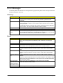
Boot
Message Displayed
60
Description
Boot Failure ...
This is a generic message indicating the BIOS could not boot from a particular
device. This message is usually followed by other information concerning the
device.
Invalid Boot Diskette
A diskette was found in the drive, but it is not configured as a bootable diskette.
Drive Not Ready
The BIOS was unable to access the drive because it indicated it was not ready for
data transfer. This is often reported by drives when no media is present.
A: Drive Error
The BIOS attempted to configure the A: drive during POST, but was unable to
properly configure the device. This may be due to a bad cable or faulty diskette
drive.
B: Drive Error
The BIOS attempted to configure the B: drive during POST, but was unable to
properly configure the device. This may be due to a bad cable or faulty diskette
drive.
Insert BOOT diskette
in A:
The BIOS attempted to boot from the A: drive, but could not find a proper boot
diskette.
Reboot and Select proper Boot device or Insert Boot Media in selected Boot device
BIOS could not find a bootable device in the system and/or removable media drive
does not contain media.
Reboot and Select
proper Boot device or
Insert Boot Media in
selected Boot device
BIOS could not find a bootable device in the system and/or removable
media drive does not contain media.
NO ROM BASIC
This message occurs on some systems when no bootable device can be detected.
Chapter 4
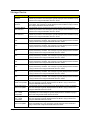
Storage Device
Message Displayed
Description
Primary Master Hard
Disk Error
The IDE/ATAPI device configured as Primary Master could not be properly
initialized by the BIOS. This message is typically displayed when the BIOS is trying
to detect and configure IDE/ATAPI devices in POST.
Primary Slave Hard
Disk Error
The IDE/ATAPI device configured as Primary Slave could not be properly initialized
by the BIOS. This message is typically displayed when the BIOS is trying to detect
and configure IDE/ATAPI devices in POST.
Secondary Master
Hard Disk Error
The IDE/ATAPI device configured as Secondary Master could not be properly
initialized by the BIOS. This message is typically displayed when the BIOS is trying
to detect and configure IDE/ATAPI devices in POST.
Secondary Slave
Hard Disk Error
The IDE/ATAPI device configured as Secondary Slave could not be properly
initialized by the BIOS. This message is typically displayed when the BIOS is trying
to detect and configure IDE/ATAPI devices in POST.
3rd Master Hard Disk
Error
The IDE/ATAPI device configured as Master in the 3rd IDE controller could not be
properly initialized by the BIOS. This message is typically displayed when the BIOS
is trying to detect and configure IDE/ATAPI devices in POST.
3rd Slave Hard Disk
Error
The IDE/ATAPI device configured as Slave in the 3rd IDE controller could not be
properly initialized by the BIOS. This message is typically displayed when the BIOS
is trying to detect and configure IDE/ATAPI devices in POST.
4th Master Hard Disk
Error
The IDE/ATAPI device configured as Master in the 4th IDE controller could not be
properly initialized by the BIOS. This message is typically displayed when the BIOS
is trying to detect and configure IDE/ATAPI devices in POST.
4th Slave Hard Disk
Error
The IDE/ATAPI device configured as Slave in the 4th IDE controller could not be
properly initialized by the BIOS. This message is typically displayed when the BIOS
is trying to detect and configure IDE/ATAPI devices in POST.
5th Master Hard Disk
Error
The IDE/ATAPI device configured as Master in the 5th IDE controller could not be
properly initialized by the BIOS. This message is typically displayed when the BIOS
is trying to detect and configure IDE/ATAPI devices in POST.
5th Slave Hard Disk
Error
The IDE/ATAPI device configured as Slave in the 5th IDE controller could not be
properly initialized by the BIOS. This message is typically displayed when the BIOS
is trying to detect and configure IDE/ATAPI devices in POST.
6th Master Hard Disk
Error
The IDE/ATAPI device configured as Master in the 6th IDE controller could not be
properly initialized by the BIOS. This message is typically displayed when the BIOS
is trying to detect and configure IDE/ATAPI devices in POST.
6th Slave Hard Disk
Error
The IDE/ATAPI device configured as Slave in the 6th IDE controller could not be
properly initialized by the BIOS. This message is typically displayed when the BIOS
is trying to detect and configure IDE/ATAPI devices in POST.
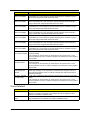
Primary Master Drive
- ATAPI Incompatible
The IDE/ATAPI device configured as Primary Master failed an ATAPI compatibility
test. This message is typically displayed when the BIOS is trying to detect and
configure IDE/ATAPI devices in POST.
Primary Slave Drive ATAPI Incompatible
The IDE/ATAPI device configured as Primary Slave failed an ATAPI compatibility
test. This message is typically displayed when the BIOS is trying to detect and
configure IDE/ATAPI devices in POST.
Secondary Master
Drive - ATAPI
Incompatible
The IDE/ATAPI device configured as Secondary Master failed an ATAPI
compatibility test. This message is typically displayed when the BIOS is trying to
detect and configure IDE/ATAPI devices in POST.
Secondary Slave
Drive - ATAPI
Incompatible
The IDE/ATAPI device configured as Secondary Slave failed an ATAPI compatibility
test. This message is typically displayed when the BIOS is trying to detect and
configure IDE/ATAPI devices in POST.
3rd Master Drive ATAPI Incompatible
The IDE/ATAPI device configured as Master in the 3rd IDE controller failed an
ATAPI compatibility test. This message is typically displayed when the BIOS is
trying to detect and configure IDE/ATAPI devices in POST.
Chapter 4
61
Message Displayed
Description
3rd Slave Drive ATAPI Incompatible
The IDE/ATAPI device configured as Slave in the 3rd IDE controller failed an ATAPI
compatibility test. This message is typically displayed when the BIOS is trying to
detect and configure IDE/ATAPI devices in POST.
4th Master Drive ATAPI Incompatible
The IDE/ATAPI device configured as Master in the 4th IDE controller failed an
ATAPI compatibility test. This message is typically displayed when the BIOS is
trying to detect and configure IDE/ATAPI devices in POST.
4th Slave Drive ATAPI Incompatible
The IDE/ATAPI device configured as Slave in the 4th IDE controller failed an ATAPI
compatibility test. This message is typically displayed when the BIOS is trying to
detect and configure IDE/ATAPI devices in POST.
5th Master Drive ATAPI Incompatible
The IDE/ATAPI device configured as Master in the 5th IDE controller failed an
ATAPI compatibility test. This message is typically displayed when the BIOS is
trying to detect and configure IDE/ATAPI devices in POST.
5th Slave Drive ATAPI Incompatible
The IDE/ATAPI device configured as Slave in the 5th IDE controller failed an ATAPI
compatibility test. This message is typically displayed when the BIOS is trying to
detect and configure IDE/ATAPI devices in POST.
6th Master Drive ATAPI Incompatible
The IDE/ATAPI device configured as Master in the 6th IDE controller failed an
ATAPI compatibility test. This message is typically displayed when the BIOS is
trying to detect and configure IDE/ATAPI devices in POST.
6th Slave Drive ATAPI Incompatible
The IDE/ATAPI device configured as Slave in the 6th IDE controller failed an ATAPI
compatibility test. This message is typically displayed when the BIOS is trying to
detect and configure IDE/ATAPI devices in POST.
S.M.A.R.T. Capable
but Command Failed
The BIOS tried to send a S.M.A.R.T. message to a hard disk, but the command
transaction failed.
This message can be reported by an ATAPI device using the S.M.A.R.T. error
reporting standard. S.M.A.R.T. failure messages may indicate the need to replace
the hard disk.
S.M.A.R.T.
Command Failed
The BIOS tried to send a S.M.A.R.T. message to a hard disk, but the command
transaction failed.
This message can be reported by an ATAPI device using the S.M.A.R.T. error
reporting standard. S.M.A.R.T. failure messages may indicate the need to replace
the hard disk.
S.M.A.R.T. Status
BAD, Backup and
Replace
A S.M.A.R.T. capable hard disk sends this message when it detects an imminent
failure.This message can be reported by an ATAPI device using the S.M.A.R.T.
error reporting standard. S.M.A.R.T. failure messages may indicate the need to
replace the hard disk.
S.M.A.R.T. Capable
and Status BAD
A S.M.A.R.T. capable hard disk sends this message when it detects an imminent
failure.
This message can be reported by an ATAPI device using the S.M.A.R.T. error
reporting standard. S.M.A.R.T. failure messages may indicate the need to replace
the hard disk.
Virus Related
Message Displayed
62
Description
BootSector Write !!
The BIOS has detected software attempting to write to a drive’s boot sector. This is
flagged as possible virus activity. This message will only be displayed if Virus
Detection is enabled in AMIBIOS setup.
VIRUS: Continue
(Y/N)?
If the BIOS detects possible virus activity, it will prompt the user. This message will
only be displayed if Virus Detection is enabled in AMIBIOS setup.
Chapter 4
System Configuration
Message Displayed
Description
DMA-1 Error
Error initializing primary DMA controller. This is a fatal error, often indication a
problem with system hardware.
DMA-2 Error
Error initializing secondary DMA controller. This is a fatal error, often indication a
problem with system hardware.
DMA Controller Error
POST error while trying to initialize the DMA controller. This is a fatal error, often
indication a problem with system hardware.
Checking
NVRAM..Update
Failed
BIOS could not write to the NVRAM block. This message appears when the FLASH
part is write-protected or if there is no FLASH part (System uses a PROM or
EPROM).
Microcode Error
BIOS could not find or load the CPU Microcode Update to the CPU. This message
only applies to INTEL CPUs. The message is most likely to appear when a brand
new CPU is installed in a mainboard with an outdated BIOS. In this case, the BIOS
must be updated to include the Microcode Update for the new CPU.
NVRAM Checksum
Bad, NVRAM
Cleared
There was an error in while validating the NVRAM data. This causes POST to clear
the NVRAM data.
Resource Conflict
More than one system device is trying to use the same non-shareable resources
(Memory or I/O).
NVRAM Ignored
The NVRAM data used to store Plug’n’Play (PnP) data was not used for system
configuration in POST.
NVRAM Bad
The NVRAM data used to store Plug’n’Play (PnP) data was not used for system
configuration in POST due to a data error.
Static Resource
Conflict
Two or more Static Devices are trying to use the same resource space (usually
Memory or I/O).
PCI I/O conflict
A PCI adapter generated an I/O resource conflict when configured by BIOS POST.
PCI ROM conflict
A PCI adapter generated an I/O resource conflict when configured by BIOS POST.
PCI IRQ conflict
A PCI adapter generated an I/O resource conflict when configured by BIOS POST.
PCI IRQ routing table
error
BIOS POST (DIM code) found a PCI device in the system but was unable to figure
out how to route an IRQ to the device. Usually this error is causing by an
incomplete description of the PCI Interrupt Routing of the system.
Timer Error
Indicates an error while programming the count register of channel 2 of the 8254
timer. This may indicate a problem with system hardware.
Refresh timer test
failed
BIOS POST found that the refresh timer hardware failed to pass the Refresh
Retrace Test.
Interrupt Controller-1
error
BIOS POST could not initialize the Master Interrupt Controller. This may indicate a
problem with system hardware.
Interrupt Controller-2
error
BIOS POST could not initialize the Slave Interrupt Controller. This may
indicate a problem with system hardware.
Chapter 4
63
CMOS
Message Displayed
Description
CMOS Date/Time Not
Set
The CMOS Date and/or Time are invalid. This error can be resolved by readjusting
the system time in AMIBIOS Setup.
CMOS Battery Low
CMOS Battery is low. This message usually indicates that the CMOS battery needs
to be replaced. It could also appear when the user intentionally discharges the
CMOS battery.
CMOS Settings
Wrong
CMOS settings are invalid. This error can be resolved by using AMIBIOS Setup.
CMOS Checksum
Bad
CMOS contents failed the Checksum check. Indicates that the CMOS data has
been changed by a program other than the BIOS or that the CMOS is not retaining
its data due to malfunction. This error can typically be resolved by using AMIBIOS
Setup.
Miscellaneous
Message Displayed
64
Description
KBC BAT Test failed
Keyboard controller BAT test failed. This may indicate a problem with keyboard
controller initialization.
Keyboard Error
Keyboard is not present or the hardware is not responding when the keyboard
controller is initialized.
PS2 Keyboard not
found
PS2 Keyboard support is enabled in the BIOS setup but the device is not detected.
PS2 Mouse not found
PS2 Mouse support is enabled in the BIOS setup but the device is not detected.
Keyboard/Interface
Error
Keyboard Controller failure. This may indicate a problem with system hardware.
Unlock Keyboard
PS2 keyboard is locked. User needs to unlock the keyboard to continue the BIOS
POST.
System Halted
The system has been halted. A reset or power cycle is required to reboot the
machine. This message appears after a fatal error has been detected.
<INS> Pressed
Indicates that <INS> key is pressed during the BIOS POST. The POST will load and
use default CMOS settings.
Password check
failed
The password entered does not match the password set in the setup. This condition
may occur for both Supervisor and User password verification.
Unknown BIOS error.
Error code = 004Ah
This message is displayed when ADM module is not present in the AMIBIOS8
ROM.
Unknown BIOS error.
Error code = 004Bh
This message is displayed when language module is not present in the AMIBIOS8
ROM.
Floppy Controller
Failure
Error in initializing legacy Floppy Controller.
Chapter 4
USB eModule Error Messages
Message Displayed
Description
Warning!
Unsupported USB
device found and
disabled!
This message is displayed when a non-bootable USB device is enumerated and
disabled by the BIOS.
Warning! Port 60h/
64h emulation is not
supported by this
USB Host Controller!
This message is displayed to indicate that port 60h/64h emulation mode cannot be
enabled for this USB host controller. This condition occurs if USB KBC emulation
option is set for non-SMI mode.
Warning! EHCI
controller disabled. It
requires 64bit data
support in the BIOS.
This message is displayed to indicate that EHCI controller is disabled because of
incorrect data structure. This condition occur if the USB host controller needs 64-bit
data structure while the USB is ported with 32-bit data structure.
SMBIOS eModule Error Messages
Message Displayed
Not enough space in
Runtime area!!.
SMBIOS data will not
be available.
Description
This message is displayed when the size of the SMBIOS data exceeds the
available SMBIOS runtime storage size.
CPU eModule Error Messages
Message Displayed
Description
Warning! This system
board does not
support the power
requirements of the
installed processor.
The processor will
be run at a reduced
frequency, which will
impact system
performance. area!!.
SMBIOS data will not
be available.
This message is displayed when the power requirements of the board do not match
the power requirement of the CPU.
MPS Table (Multi-processor) eModule Error Messages
Message Displayed
Description
Insufficient Runtime
space for MPS data!
System may operate
in PIC or Non-MPS
mode.
This message is displayed when there is not enough space in the 0F000h runtime
area for creating MPS table.
Chapter 4
65
Beep Codes
Beep codes are used by the BIOS to indicate a serious or fatal error to the end user. Beep codes are used
when an error occurs before the system video has been initialized. Beep codes will be generated by the
system board speaker, commonly referred to as the PC speaker.
AMIBIOS displays the checkpoints in the bottom right corner of the screen during POST. This display method
is limited, since it only displays checkpoints that occur after the video card has been activated.
Not all computers using AMIBIOS enable this feature. In most cases, a checkpoint card is the best tool for
viewing AMIBIOS checkpoints.
Beep Symptom
66
Cause and Description
One short beep
System is ready.
System is OK.
Continuous one long beep
Memory not installed or memory error.
One long beep and two short beeps
then repeat.
VGA not installed or VGA error.
Graphics card error/not installed, graphics card memory error or
graphics card BIOS checksum error.
One long beep then two short beep
BIOS damaged.
BIOS is damaged, BIOS POST jumps to Boot Block to execute the
default procedures.
Two short beeps
CMOS damaged.
CMOS checksum error or CMOS battery loss occurs.
Chapter 4
Index of Symptom-to-FRU Error Message
NOTE: To diagnose a problem, first find the error symptom in the left column. If directed to a check procedure,
replace the FRU indicated in the check procedure. If no check procedure is indicated, the first Action/
FRU listed in the right column is the most likely cause.
Processor/Processor Fan-Related Symptoms
Symptom / Error
Processor fan does not run but power
supply fan runs.
Action/FRU
Processor test failed.
Ensure the system is not in power saving mode.
With the system power on, measure the voltage of processor
fan connector. Its reading should be +12Vdc. Its reading
should be +12Vdc. If the reading shows normal, but the fan
still does not work, then replace a good fan.
Mainboard
Processor
Mainboard
NOTE: Normally, the processor fan should be operative, and the processor clock setting should be exactly set
to match its speed requirement before diagnosing any processor problems.
Mainboard and memory-Related Symptoms
Symptom / Error
Memory test failed.
Action/FRU
Incorrect memory size shown or repeated
during POST.
System works but fails to enter power
saving mode when the Power
Management Mode is set to Enabled.
Blinking cursor only; system does not
work.
Memory module
Mainboard
Insert the memory modules in the DIMM sockets properly,
then reboot the system.
Memory module
Mainboard
Enter BIOS Setup and load default settings.In Windows
Systems, check settings in Power Management Property of
Control Panel.
Reload software from Recovery CD.
Diskette/IDE drive connection/cables
Diskette/IDE disk drives
See “Undetermined Problems”.
Mainboard
NOTE: Ensure the memory modules are installed properly and the contact leads are clean before diagnosing
any system problems.
Chapter 4
67
Diskette Drive-Related Symptoms
Symptom / Error
Media and drive are mismatched.
Action/FRU
Diskette drive does not work.
Diskette drive read/write error.
Diskette drive LED comes on for more than
2 minutes when reading data.
Diskette drive LED fails to light, and the
drive is unable to access for more than 2
minutes.
Diskette drive test failed.
Ensure the diskette drive is configured correctly in the Disk
Drives of BIOS Setup.
Ensure the diskette drive is correctly formatted.
Diskette drive connection/cable
Diskette drive
Mainboard
Ensure the diskette drive is not set to None in the Disk Drives
of BIOS Setup.
Diskette drive power
Diskette drive connection/cable
Diskette drive
Mainboard
Diskette
Diskette drive cable
Diskette drive
Mainboard
Diskette
Diskette drive cable
Diskette drive
Mainboard
Diskette
Diskette drive power
Diskette drive connection/cable
Diskette drive
Mainboard
Diskette
Diskette drive cable
Diskette drive
Mainboard
NOTE: Ensure the diskette drive is auto-setting in BIOS Setup and its read/write head is clean before
diagnosing any diskette drive problems.(If only one drive is installed, please make sure the drive is
connected to master connector or the drive is set to master.)
68
Chapter 4
Hard Disk Drive-Related Symptoms
Symptom / Error
Hard disk drive test failed.
Action/FRU
Hard disk drive cannot format completely.
Hard disk drive has write error.
Hard disk drive LED fails to light, but
system operates normally.
Enter BIOS Setup and Load default settings
Hard disk drive cable
Hard disk drive
Mainboard
Enter BIOS Setup and Load default settings
Hard disk drive cable
Hard disk drive
Mainboard
Enter BIOS Setup and Load default settings
Hard disk drive
With the system power on, measure the voltage of hard disk
LED connector.
Hard drive LED cable
NOTE: Ensure hard disk drive is configured correctly in BIOS Setup, cable/jumper are set correctly before
diagnosing any hard disk drive problems. (If only one drive is installed, please make sure the drive is
connected to master connector or the drive is set to master.)
CD/DVD-ROM Drive-Related Symptoms
Symptom / Error
CD/DVD-ROM drive LED doesn't come on
but works normally.
Action/FRU
CD/DVD-ROM drive LED flashes for more
than 30 seconds before LED shutting off.
Software asks to reinstall disc. Software
displays a reading CD/DVD error.
CD/DVD-ROM drive cannot load or eject
when the system is turned on and its eject
button is pressed and held.
CD/DVD-ROM drive does not read and
there are no messages are displayed.
CD/DVD-ROM drive can play audio CD but
no sound output.
Run “Load Setup Defaults” in BIOS Setup Utility, then reboot
system.
DIMM
Mainboard
CD/DVD-ROM may have dirt or foreign material on it. Check
with a known good disc.
CD/DVD-ROM is not inserted properly.
CD/DVD-ROM is damaged.
Disconnect all cables from CD/DVD-ROM drive except
power cable, then press eject button to try to unload the disk.
CD/DVD-ROM drive power.
CD/DVD-ROM drive
CD may have dirt or foreign material on it. Check with a
known good disc.
Ensure the CD/DVD-ROM driver is installed properly.
CD/DVD-ROM drive.
Ensure the headphone jack of the CD/DVD-ROM has an
output.
Turn up the sound volume.
Speaker power/connection/cable.
CD/DVD-ROM drive.
NOTE: Ensure CD/DVD-ROM drive is configured correctly in BIOS Setup, cable/jumper are set correctly and
its laser beam is clean before diagnosing any CD/DVD-ROM drive problems.
Chapter 4
69
Real-Time Clock-Related Symptoms
Symptom / Error
Real-time clock is inaccurate.
Action/FRU
Ensure the information in the Standard CMOS Feature of
BIOS Setup is set correctly.
RTC battery
Mainboard
Speaker power/connection/cable.
Audio-Related Symptoms
Symptom / Error
Audio software program invokes but no
sound comes from speakers.
Action/FRU
Modem-Related Symptoms
Symptom / Error
Modem ring cannot wake up system from
suspend mode.
Action/FRU
For the External Modem, make sure Power on By Ring in
BIOS Setup or Power Management is set to Enabled. For the
PCI modem, make sure Wake up by PCI card is set to
Enabled.
If PCI modem card is used, reinsert the modem card to PCI
slot firmly or replace the modem card.
In Win 98, ensure the telephone application is configured
correctly for your modem and set to receive messages and/
or fax.
Data/fax modem software program invokes
but cannot receive/send data/fax
Ensure the modem card is installed properly.
Fax/voice modem software program
invokes but has no sound output. (Data files
are received normally; voice from modem
cannot be produced, but system sound
feature works normally.)
Ensure the modem voice-in cable from modem adapter card
to mainboard
Video and Monitor-Related Symptoms
Symptom / Error
Video memory test failed.Video adapter
failed.
Action/FRU
Display problem:
- Incorrect colors
- No high intensity
- Missing, broken, or incorrect characters
- Blank monitor (dark)
- Blank monitor (bright)
- Distorted image
- Unreadable monitor
Display changing colors.
70
Remove all non-factory-installed cards.
Load default settings (if screen is readable).
Mainboard
Monitor signal connection/cable.
Monitor
Video adapter card
Mainboard
Monitor signal connection/cable.
Video adapter card
Mainboard
Chapter 4
Video and Monitor-Related Symptoms
Symptom / Error
Serial or parallel port loop-back test failed.
Action/FRU
Printing failed.
Ensure the printer driver is properly installed. Refer to the
printer service manual.
Printer.
Printer cable.
Mainboard.
Refer to the service manual for the printer.
Keyboard
Printer problems.
Make sure that the LPT# or COM# you test is the same as
the setting in BIOS Setup.
Loop-back.
Mainboard
Keyboard-Related Symptoms
Symptom / Error
Some or all keys on keyboard do not work.
Check or do the following in sequence
Power Supply-Related Symptoms
Symptom / Error
Check or do the following in sequence
Pressing power switch does not turn off
system. (Only unplugging the power cord
from electrical outlet can turn off the
system.)
Pressing power switch does not turn on the
system
Executing software shutdown from
Windows98 Start menu does not turn off the
system. (Only pressing power switch can
turn off the system).
No system power, or power supply fan is
not running.
Ensure the Soft-off by PWR-BTTN. in BIOS Setup of Power
Management is not set to Instant-off.
Power switch cable assembly
Ensure the power override switch (situated at the back of the
machine, just above the connector for the power cable) is not
set to OFF.
Power switch cable assembly.
Load default settings.
Reload software from Recovery CD.
Power Supply
Mainboard
NOTE: If you cannot find a symptom or an error in this list and the problem remains, see “Undetermined
Problems” on page 74.
Chapter 4
71
BIOS Recovery
1.
Prepare a USB storage device and keep it ready in hand.
(1). Connect the USB storage device to a USB port on your computer.
(2). Copy the target BIOS ROM file to a USB storage device.
(3). Rename the target BIOS to “amiboot.rom”.
(4). Unplug the USB storage device.
72
2.
Connect the USB storage device on the USB port on the system.
3.
Power on the system. The system initializes the BIOS recovery process. Wait for about 3 minutes and the
system will reboot automatically after the flash update is completed.
Chapter 4
4.
Press Delete to run the Setup Utility.
5.
In the Setup Utility, select Load Default Settings, then press Enter.
6.
Select Ok, then press Enter.
7.
Select Save & Exit Setup, then press Enter.
8.
Select Ok, then press Enter.
Chapter 4
73
Undetermined Problems
The diagnostic problems does not identify which adapter or device failed, which installed devices are incorrect,
whether a short circuit is suspected, or whether the system is inoperative.
NOTE: Verify that all attached devices are supported by the computer.
NOTE: Verify that the power supply being used at the time of the failure is operating correctly. (See “Power
System Check” on page 54.)
Follow procedures below to isolate the failing FRU. Do not isolate non-defective FRU.
74
1.
Power off the computer.
2.
Visually check them for damage. If any problems are found, replace the FRU.
3.
Remove or disconnect all of the following devices:
Non-Acer devices
Printer, mouse, and other external devices
Hard disk drive
DIMM
CD/DVD-ROM drive
Adapter cards
4.
Power on the computer.
5.
Determine if the problem has been resolved.
6.
If the problem does not recur, reconnect the removed devices one at a time until you find the failed FRU.
7.
If the problem persists, replace the FRU one at a time. Do not replace a non-defective FRU.
Chapter 4
Chapter 5
System Block Diagram and Board Layout
System Block Diagram
Chapter 5
75
Mainboard Layout
No
Code
Description
1
KB/MS
Top: PS2 Mouse port
Bottom: PS2 Keyboard port
2
HDMI1
HDMI port
3
VGA1
VGA (D-sub) port
4
USBESATA1
USB ports
5
USBLAN1
Top: Network port
Bottom: USB ports
6
AUDJACK
Line-in/Side surround jack
Line-Out Line-out jack
Microphone/line-in jack
76
7
PWR2
Processor power connector
8
REAR_FAN
System fan connector
9
CPU_FAN
Processor fan connector
Chapter 5
No
Code
Description
10
DIMM 1-4
DIMM slots
11
F_USB1, 2 and 4
Card reader USB cable connectors
12
PWR1
Main power connector
13
F_USB3
Front panel USB connector
14
GPIO1-2
GPIO1~2 Reserve headers
15
SATA 1-2
SATA connectors
16
BIOS_FLASH
BIOS flash connector
17
FRONT_PANEL1
Front panel connector
18
TPM
Trusted platform module connector
19
CLR_CMOS
Clear CMOS jumper
20
PCH_ME_ENABLE
PCH_ME_ENABLE jumpers
21
PCI-E1_16X
PCI Express x16 slot
22
SPDIFI_OUT
S/PDIF port
23
SPEAKER1
Internal speaker connector
24
F_AUDIO
Front panel audio connector
25
PCI_E1_1x2
PCI Express x2 slot
Chapter 5
77
78
Chapter 5
Chapter 6
FRU (Field Replaceable Unit) List
This chapter offers the FRU (Field Replaceable Unit) list in global configuration of the X3950 or X5950 desktop
computer. Refer to this chapter whenever ordering the parts to repair or for RMA (Return Merchandise
Authorization).
NOTES:
Chapter 6
When ordering FRU parts, check the most up-to-date information available on your regional web
or channel. For whatever reasons a part number is changed, it will NOT be noted on the printed
Service Guide. For Acer authorized service providers, your Acer office may have a different part
number code from those given in the FRU list of this printed Service Guide. You MUST use the
local FRU list provided by your regional Acer office to order FRU parts for service.
To scrap or to return the defective parts, follow the local government ordinance or regulations on
how to dispose it properly, or follow the rules set by your regional Acer office on how to return it.
This document will be updated as more information about the FRU list becomes available.
79
Exploded Diagram
X3950 model
No.
80
Part Name
No.
16
Part Name
1
ASSY POWER BUTTON BOXER X350
PLT POWER LOGO BOXER X350
2
BEZEL FRONT BOXER X351
17
PROTECT FILM F-BEZEL BOXER X350
3
C.A. LED SWITCH BOXER X350
18
PROTECT FILM F-BEZEL-R-BOXER X350
4
CVR FRONT BOXER X350
19
PROTECT FILM F-IO BOXER X351
5
CVR LIGHT BOXER X350
20
PROTECT FILM IO-DOOR-BOXER X350
6
CVR P[OWER BOXER X350
21
SCRW TAP PAN M3*L8 2 LEAD
7
DOOR IO BOXER X350
22
SPG ODD LINK BOXER X310
8
DOOR ODD BOXER X350
23
SPG POWER BOXER X310
9
IO DOOR BKT
24
SPRING ODD DOOR HD206A
10
KNOB ODD BOXER X350
25
ASSY L CASE - ASM BOXER X550
11
KNOB ODD LINK A BOXER X350
26
SCRW #6-32 L5 PAN NI
12
KNOB ODD LINK B BOXER X350
27
CAS UP BOXER X550
13
MAGNET 10*6*3
28
FRONT IO BRACKET
14
MYLAR LIGHT COVER BOXER X350
29
ODD BRACKET
15
PLT ACER-LOGO-BOXER-X5
30
HDD BRACKET
Chapter 6
X5950 model
No.
Part Name
No.
17
Part Name
1
PLT ACER LOGO BOXER X5
PLT ASPIRE LOGO BOXER X550
2
BEZEL FRONT B BOXER X550
18
PLT ODD KNOB LOGO BOXER X550
3
CVR COSMETIC ART WORK BOXER X550
19
PROTECT FILM CVR FRONT BOXER X550
4
CVR COSMETIC BOXER X550
20
PROTECT FILM DOOR ODD BOXER X550
5
CVR FRONT BOXER X550
21
PROTECT FILM F-IO BOXER X550
6
DOOR FIO LINK A BOXER X550
22
PROTECT FILM KNOB ODD BOXER X550
7
DOOR FIO LINK B BOXER X550
23
SPG ODD LINK BOXER X310
8
DOOR IO BOXER X550
24
SPRING ODD DOOR HD206A
9
DOOR ODD BOXER X550
25
ASSY L CASE - ASM BOXER X550
10
GEAR PG-07A 7G
26
ASSY TOP-COVER BOXER X550
11
IO DOOR BKT
27
CAS UP BOXER X550
12
KNOB ODD BOXER X550
28
SCRW #6-32 L5 PAN NI
13
KNOB ODD LINK A BOXER X350
29
FRONT IO BRACKET
14
KNOB ODD LINK B BOXER X350
30
ODD BRACKET
15
LATCH DOOR BOXER X5
31
HDD BRACKET
16
MAGNET 10*6*3
Chapter 6
81
X3950 FRU List
System model: PV.SE602.004 AX3950 AAP AJC PV.SE602.004
Category
Part Name
Acer Part No.
BOARDS
FRONT IO BOARD CENTURY W/AUDIO CABLE*1&USB CABLE*2
55.SC101.001
CARD READER 9 IN 1 8.5L AU6476 W/USB2.0 & USB CABLE W/O 1394 CR.10400.107
CABLES
POWER CORD 125V 7A 3G JAPAN
27.01518.181
ODD SATA CABLE
50.SD101.001
HDD SATA CABLE
50.SD101.002
LED SWITCH CABLE
TBD
CASE/COVER/BRACKET ASSEMBLY
82
FRONT IO BRACKET
TBD
ASSEMBLY MAIN CHASSIS W/UCASE & LCASE FOR BOXER X350
TBD
UPPER CASE BOXER X350
TBD
ASSEMBLY LOWER CASE FOR BOXER X350
TBD
HDD&ODD COVER BRACKET
33.SC101.002
FRONT BEZEL W/LED SWITCH CABLE FOR X350
TBD
Chapter 6
CPU/PROCESSOR
CPU INTEL CORE I3-530 LGA 2.93G 4M 1333FSB 1156 73W
CLARKDALE C-2 DUAL CORE
KC.53001.CI3
ODD PLDS SUPER-MULTI DRIVE HH 16X DH-16AASH BLACK BEZEL
SATA FOR HF+WINDOWS7
KU.0160F.009
DVD-RW DRIVE
HDD/HARD DISK DRIVE
HDD 3.5" 500GB 7200RPM SATA SEAGATE PHARAOH ST3500418AS
KH.50007.012
CPU HEATSINK AIR COOLER LGA1156 95W WITH DUCT
HI.10800.071
KEYBOARD USB 109 KEY BLACK JAPANESE W/O EKEY
KB.USB0B.199
MAINBOARD AX1900 INTEL G41 ICH7 GMA X4500 W/RTC BATTERY
W/O CPU&MEMORY
MB.SE509.001
MEMORY SAMSUNG DDR3 1333MHZ 2G UNB-UFFERED DIMM W/O
ECC F DIE (46NM)
KN.2GB0H.009
LOGITECH 0810_USB OPTICAL MOUSE USB M-UAY-ACR2
MS.11200.018
POWER SUPPLY 220W NPFC 115V/230V LITEON PS-5221-06A1-ROHS
EUP
PY.2200F.006
HEATSINK
KEYBOARD
MAINBOARD
MEMORY
POINTING DEVICE
POWER SUPPLY
SCREWS
Chapter 6
SCREW I NO6-32 L5 BZN
86.00J07.B60
SCREW PAN #6-32 L6 NI BOXER WZS
86.00J44.C60
SCREW #6-32 L5 PAN NI
86.00J90.B60
SCREW NO4-40 L6.5 PAN NI
86.00N03.B40
SCRW PAN M3 L5 BZN
86.1A324.5R0
SCREW FLAT #6-32*3/16 NI
86.5A5B6.012
83
System model: PT.SE602.003 AX3950 AAP ACS PT.SE602.003
Category
Part Name
OEM Part No.
BOARDS
FRONT IO BOARD CENTURY W/AUDIO CABLE*1&USB CABLE*2
55.SC101.001
CARD READER 9 IN 1 8.5L AU6476 W/USB2.0 & USB CABLE W/O 1394 CR.10400.107
WIRELESS LAN BOARD 802.11BGN LITEON WN7600R
NI.10200.009
POWER CORD 250V 3PIN 1800MM UK
27.01518.181
ODD SATA CABLE
50.SD101.001
HDD SATA CABLE
50.SD101.002
LED SWITCH CABLE
TBD
CABLES
CASE/COVER/BRACKET ASSEMBLY
84
FRONT IO BRACKET
TBD
ASSEMBLY MAIN CHASSIS W/UCASE & LCASE FOR BOXER X350
TBD
UPPER CASE BOXER X350
TBD
ASSEMBLY LOWER CASE FOR BOXER X350
TBD
HDD&ODD COVER BRACKET
33.SC101.002
FRONT BEZEL W/LED SWITCH CABLE FOR X350
TBD
Chapter 6
CPU/PROCESSOR
CPU INTEL CORE I3-530 LGA 2.93G 4M 1333FSB 1156 73W
CLARKDALE C-2 DUAL CORE
KC.53001.CI3
ODD PLDS SUPER-MULTI DRIVE HH 16X DH-16AASH BLACK BEZEL
SATA FOR HF+WINDOWS7
KU.0160F.009
DVD-RW DRIVE
HDD/HARD DISK DRIVE
HDD 320GB 3.5" 7200RPM SATA II SEAGATE PHARAOH 8MB NCQ
KH.32007.011
CPU HEATSINK AIR COOLER LGA1156 95W WITH DUCT
HI.10800.071
KEYBOARD USB 104 KEY CHICONY KU-07603US25522V BLACK US
W/O EKEY
KB.USB0B.158
MAINBOARD AX1900 INTEL G41 ICH7 GMA X4500 W/RTC BATTERY
W/O CPU&MEMORY
MB.SE509.001
MEMORY SAMSUNG DDR3 1333MHZ 2G UNB-UFFERED DIMM W/O
ECC F DIE (46NM)
KN.2GB0H.009
LOGITECH 0810_USB OPTICAL MOUSE USB M-UAY-ACR2
MS.11200.018
POWER SUPPLY 220W NPFC 115V/230V LITEON PS-5221-06A1-ROHS
EUP
PY.2200F.006
SCREW I NO6-32 L5 BZN
86.00J07.B60
HEATSINK
KEYBOARD
MAINBOARD
MEMORY
POINTING DEVICE
POWER SUPPLY
SCREWS
SCREW PAN #6-32 L6 NI BOXER WZS
86.00J44.C60
SCREW #6-32 L5 PAN NI
86.00J90.B60
SCRW PAN M3 L5 BZN
86.1A324.5R0
SCREW FLAT #6-32*3/16 NI
86.5A5B6.012
SPEAKER CHIAMAW 9M-20A200-000 ACER LOGO LF 0810
SP.10600.011
SPEAKER
Chapter 6
85
System model: PT.SE602.004 AX3950 AAP ACS PT.SE602.004
Category
Part Name
Acer Part No.
BOARDS
FRONT IO BOARD CENTURY W/AUDIO CABLE*1&USB CABLE*2
55.SC101.001
CARD READER 9 IN 1 8.5L AU6476 W/USB2.0 & USB CABLE W/O 1394 CR.10400.107
WIRELESS LAN BOARD 802.11BGN LITEON WN7600R
NI.10200.009
VGA CARD PCPARTNER 288-1N141-A00AC NVIDIA GT315 512MB
SDDR3 DVI+HDMI ATX (SAMSUNG)
VG.PCPT3.154
POWER CORD 250V 3PIN 1800MM UK
27.01518.181
ODD SATA CABLE
50.SD101.001
HDD SATA CABLE
50.SD101.002
DVI TO VGA DONGLE CONNECTOR
D0.VGA26.P01
LED SWITCH CABLE
TBD
CABLES
CASE/COVER/BRACKET ASSEMBLY
86
FRONT IO BRACKET
TBD
ASSEMBLY MAIN CHASSIS W/UCASE & LCASE FOR BOXER X350
TBD
UPPER CASE BOXER X350
TBD
ASSEMBLY LOWER CASE FOR BOXER X350
TBD
HDD&ODD COVER BRACKET
33.SC101.002
Chapter 6
FRONT BEZEL W/LED SWITCH CABLE FOR X350
TBD
CPU INTEL CORE I3-530 LGA 2.93G 4M 1333FSB 1156 73W
CLARKDALE C-2 DUAL CORE
KC.53001.CI3
ODD PLDS SUPER-MULTI DRIVE HH 16X DH-16AASH BLACK BEZEL
SATA FOR HF+WINDOWS7
KU.0160F.009
CPU/PROCESSOR
DVD-RW DRIVE
HDD/HARD DISK DRIVE
HDD 3.5" 500GB 7200RPM SATA SEAGATE PHARAOH ST3500418AS
KH.50007.012
CPU HEATSINK AIR COOLER LGA1156 95W WITH DUCT
HI.10800.071
KEYBOARD RF2.4 104KEY CHYCONY KG-0766 104K BLACK US
KB.RF403.362
MAINBOARD AX1900 INTEL G41 ICH7 GMA X4500 W/RTC BATTERY
W/O CPU&MEMORY
MB.SE509.001
MEMORY SAMSUNG DDR3 1333MHZ 2G UNB-UFFERED DIMM W/O
ECC F DIE (46NM)
KN.2GB0H.009
POWER SUPPLY 220W NPFC 115V/230V LITEON PS-5221-06A1-ROHS
EUP
PY.2200F.006
SCREW I NO6-32 L5 BZN
86.00J07.B60
HEATSINK
KEYBOARD
MAINBOARD
MEMORY
POWER SUPPLY
SCREWS
SCREW PAN #6-32 L6 NI BOXER WZS
86.00J44.C60
SCREW #6-32 L5 PAN NI
86.00J90.B60
SCREW NO4-40 L6.5 PAN NI
86.00N03.B40
SCRW PAN M3 L5 BZN
86.1A324.5R0
SCREW FLAT #6-32*3/16 NI
86.5A5B6.012
SPEAKER CHIAMAW 9M-20A200-000 ACER LOGO LF 0810
SP.10600.011
SPEAKER
Chapter 6
87
System model: PT.SE602.005 AX3950 AAP ACS PT.SE602.005
Category
Part Name
OEM Part No.
BOARDS
FRONT IO BOARD CENTURY W/AUDIO CABLE*1&USB CABLE*2
55.SC101.001
CARD READER 9 IN 1 8.5L AU6476 W/USB2.0 & USB CABLE W/O 1394 CR.10400.107
WIRELESS LAN BOARD 802.11BGN LITEON WN7600R
NI.10200.009
VGA CARD PCPARTNER 288-5N118-A10AC NVIDIA GT320 1GB SDDR3
DVI+HDMI LP (SAMSUNG)
VG.PCPT3.212
POWER CORD 250V 3PIN 1800MM UK
27.01518.181
ODD SATA CABLE
50.SD101.001
HDD SATA CABLE
50.SD101.002
DVI TO VGA DONGLE CONNECTOR
D0.VGA26.P01
LED SWITCH CABLE
TBD
CABLES
CASE/COVER/BRACKET ASSEMBLY
88
FRONT IO BRACKET
TBD
ASSEMBLY MAIN CHASSIS W/UCASE & LCASE FOR BOXER X350
TBD
UPPER CASE BOXER X350
TBD
ASSEMBLY LOWER CASE FOR BOXER X350
TBD
HDD&ODD COVER BRACKET
33.SC101.002
Chapter 6
FRONT BEZEL W/LED SWITCH CABLE FOR X350
TBD
CPU INTEL CORE I5-650 LGA 3.2G 4M 1333FSB 1156 C-2 73W
CLARKDALE DUAL CORE
KC.65001.CI5
ODD PLDS SUPER-MULTI DRIVE HH 16X DH-16AASH BLACK BEZEL
SATA FOR HF+WINDOWS7
KU.0160F.009
CPU/PROCESSOR
DVD-RW DRIVE
HDD/HARD DISK DRIVE
HDD 1TB 3.5" 7200RPM SATA HGST SATURN HDT721010SLA360
KH.01K01.007
CPU HEATSINK AIR COOLER LGA1156 95W WITH DUCT
HI.10800.071
KEYBOARD RF2.4 104KEY CHYCONY KG-0766 104K BLACK US
KB.RF403.362
MAINBOARD AX1900 INTEL G41 ICH7 GMA X4500 W/RTC BATTERY
W/O CPU&MEMORY
MB.SE509.001
MEMORY SAMSUNG DDR3 1333MHZ 2G UNB-UFFERED DIMM W/O
ECC F DIE (46NM)
KN.2GB0H.009
POWER SUPPLY 220W NPFC 115V/230V LITEON PS-5221-06A1-ROHS
EUP
PY.2200F.006
SCREW I NO6-32 L5 BZN
86.00J07.B60
HEATSINK
KEYBOARD
MAINBOARD
MEMORY
POWER SUPPLY
SCREWS
SCREW PAN #6-32 L6 NI BOXER WZS
86.00J44.C60
SCREW #6-32 L5 PAN NI
86.00J90.B60
SCREW NO4-40 L6.5 PAN NI
86.00N03.B40
SCRW PAN M3 L5 BZN
86.1A324.5R0
SCREW FLAT #6-32*3/16 NI
86.5A5B6.012
SPEAKER CHIAMAW 9M-20A200-000 ACER LOGO LF 0810
SP.10600.011
SPEAKER
Chapter 6
89
X5950 FRU List
System model: 91.3CY01.002G AAGASSI PVT/MVB SKU AX5950
Category
Part Name
Acer Part No.
BOARDS
FRONT IO BOARD CENTURY W/AUDIO CABLE*1&USB CABLE*2
55.SC101.001
CARD READER 9 IN 1 8.5L AU6476 W/USB2.0 & USB CABLE W/O 1394 CR.10400.107
VGA CARD PCPARTNER 288-5N118-A10AC NVIDIA GT320 1GB SDDR3
DVI+HDMI LP (SAMSUNG)
VG.PCPT3.212
POWER CORD 250V 3PIN 1800MM UK
27.01518.181
ODD SATA CABLE
50.SD101.001
HDD SATA CABLE
50.SD101.002
DVI TO VGA DONGLE CONNECTOR
D0.VGA26.P01
LED SWITCH CABLE
50.SE301.002
CABLES
CASE/COVER/BRACKET ASSEMBLY
90
FRONT IO BRACKET
33.SE301.001
ASSY MAIN-CHASSIS H57 BOXER X550
60.SE501.001
UPPER CASE BOXER X550
60.SE301.002
ASSEMBLY TOP COVER W/LED SWITCH CABLE FOR BOXER X550
60.SE301.004
LOWER CASE
60.SE501.002
HDD&ODD COVER BRACKET
33.SC101.002
Chapter 6
FRONT BEZEL FOR X550
60.SE301.005
CPU INTEL CORE I5-650 LGA 3.2G 4M 1333FSB 1156 C-2 73W
CLARKDALE DUAL CORE
KC.65001.CI5
ODD PLDS SUPER-MULTI DRIVE HH 16X DH-16AASH BLACK BEZEL
SATA FOR HF+WINDOWS7
KU.0160F.009
CPU/PROCESSOR
DVD-RW DRIVE
HDD/HARD DISK DRIVE
HDD 640GB 3.5" 7200RPM SATA II WD WD6400AAKS-22A7B2 XL320-M KH.64007.001
HEATSINK
CPU HEATSINK AIR COOLER LGA1156 95W WITH DUCT
HI.10800.071
KEYBOARD USB 104KEY LITEON SK-9625S SILVER US NEW SILVER
COLOR AC-MT-
KB.USB0B.203
MAINBOARD AX1900 INTEL G41 ICH7 GMA X4500 W/RTC BATTERY
W/O CPU&MEMORY
MB.SE509.001
MEMORY SAMSUNG DDR3 1333MHZ 2G UNB-UFFERED DIMM W/O
ECC F DIE (46NM)
KN.2GB0H.009
MOUSE USB OPT SM-9625S LITEON NEW SILVER COLOR AC-MT-113
MS.11200.068
POWER SUPPLY 220W NPFC 115V/230V LITEON PS-5221-06A1-ROHS
EUP
PY.2200F.006
KEYBOARD
MAINBOARD
MEMORY
POINTING DEVICE
POWER SUPPLY
SCREWS
Chapter 6
SCREW I NO6-32 L5 BZN
86.00J07.B60
SCREW PAN #6-32 L6 NI BOXER WZS
86.00J44.C60
SCREW #6-32 L5 PAN NI
86.00J90.B60
SCREW NO4-40 L6.5 PAN NI
86.00N03.B40
SCRW PAN M3 L5 BZN
86.1A324.5R0
SCREW FLAT #6-32*3/16 NI
86.5A5B6.012
91
SPEAKER
SPEAKER USB NEOSONICA NEW SILVER COLOR AC-MT-113
92
SP.10600.035
Chapter 6
Appendix A
Technical Specifications
This section provides technical specifications for the system.
Processor
Item
Specification
Type
Intel Core processor family
Processor Number
i7-860/870
i5-750
i5-650/660/
661/670
i3-540
G6950
Number of Cores
Quad (45 nm)
Quad (45 nm)
Dual (32 nm)
Dual (32 nm)
Dual (32 nm)
Clock Speed (GHz)
2.8/2.933
2.66
3.2/3.33/3.33/
3.46
3.06
2.8
Intel Pentium
Bus Speed (GT/s DMI)
2.5
2.5
2.5
2.5
2.5
Cache Size (MB)
8
8
4
4
3
Voltage (V)
0.65 - 1.4 V
0.65 - 1.4 V
0.65 - 1.4 V
0.65 - 1.4 V
0.65 - 1.4 V
Socket
LGA 1156
Thermal Design
Power (W)
95
95
73/87
73
73
System Board Major Chips
Item
Specification
System Core Logic
Intel P55 Express chipset
Memory Controller
Intel P55 Express chipset
Storage Controller
Intel P55 Express chipset
PCIE Controller
Intel P55 Express chipset
LAN Controller
Intel PCI-E Gbe LAN controller PHY
Audio Controller
Realtek ALC888S-VC HD Audio Codec 7.1
Input Devices
Controller
Super I/O IT8721F
Appendix A
93
System Memory
Item
Specification
DIMM Sockets
Four
Memory Type
DDR3-800/1066/1333 unbuffered DIMM
Module Name
PC3-8500/10600
Organization
ECC
Maximum Memory
8 GB
Vendor
Samsung
Unifosa
Apacer
Model Name
- M378B2873EH1-CH9
- M378B2873FHS-CH9
- M378B5673EH1-CH9
- M378B5673FH0-CH9
- GU502203EP0201
- GU512303EP0202
- 75.073C1.G02
- 75.A73C1.G02
DIMM Size (GB)
1, 2
1, 2
1, 2
Pin
240
240
240
System BIOS
Item
Specification
BIOS Vendor
American Megatrends Inc.
BIOS Version
P01-A0
PCI Interface
Item
Specification
Number of Slots
PCI Express x 1 slot
PCI Express x16 slot
Hard Disk Drive
94
Item
Specification
Vendor
WD
Seagate
HGST
Model No.
WD1600AAJS-22L7A0
WD3200AAJS-22L7A0
WD6400AAKS-22A7B2
WD10EAVS-00D7B1
ST3160815AS
ST3320813AS
ST3640623AS
HDT721016SLA380
HDT721032SLA380
HDT721064SLA360
Interface
SATA II
SATA II
SATA II
Size
3.5-inch
3.5-inch
3.5-inch
Transfer Rate (Gb/s)
3
3
3
Spindle Speed (RPM)
7200
7200
7200
Capacity (GB)
160, 320, 640, 1000
160, 320, 640
160, 320, 640
Cache (MB)
160/320/1000 GB: 8
640 GB: 16
160/320 GB: 8
340 GB: 16
160/320 GB: 8
640 GB: 16
Appendix A
VGA Interface
Item
Specification
Connector
VGA/monitor port
Network Interface
Item
Specification
LAN Controller
Intel PCI-E Gbe LAN controller PHY
Supports LAN Protocol
10/100/1000 Mbps
LAN Connector Type
RJ45
SATA Interface
Item
Specification
SATA Controller
Embedded SATA controller
Connectors
Two onboard SATA ports
Audio Interface
Item
Specification
Audio Controller
Realtek ALC888S-VC HD Audio Codec 7.1
Connectors
Three audio jacks
Appendix A
95
Keyboard and Input Devices
Item
Specification
Controller
Super I/O IT8721F
Connectors
•
PS2 keyboard and mouse connector
•
Eleven USB ports (five on front and six on rear)
Optical Drive
BD Combo Module
96
Item
Specification
Vendor
HLDS
PLDS
Model name
CH20N
BH-30N/BH-20F
DH-403S/DH-6E2S
Drive type
BD-Combo
BD-Rewriter
BD-Combo
Write Speed
DVD-R2x, 4x CLV, 8x
ZCLV, 8x PCAV, 12x
PCAV, 16x CAV
DVD-R DL 2x, 4x CLV
DVD-RW2x, 4x, 6x CLV
DVD-RAM2x, 3x CLV, 5x
PCAV
DVD+R2.4x, 4x CLV, 8x
ZCLV, 8x PCAV, 12x
PCAV, 16x CAV
DVD+R DL2.4x, 4x CLV
DVD+RW2.4x, 4x, 6x
CLV, 8x ZCLV
CD-R8x, 16x CLV, 24x,
32x PCAV, 40x CAV
CD-RW4x, 10x, 16x CLV,
24x ZCLV
BD-R (SL/DL) 2x,
4x CLV, 6x PCAV /
2x,4xCLV,6xPCAV
BD-R (SL L to H) 2x
CLV
BD-RE (SL/DL) 2x/
2x CLV
DVD-R 2x, 4x CLV,
8x ZCLV, 8x, 12x
PCAV, 16x CAV
DVD-R DL 2x, 4x
CLV
DVD-RW (SL/DL)
1x, 2x, 4x, 6x CLV /
Not support
DVD-RAM 2x, 3x
CLV, 3-5x PCAV
DVD+R 2.4x, 4x
CLV, 8x ZCLV, 8x,
12x PCAV, 16x CAV
DVD+R DL 2.4x, 4x
CLV
DVD+RW (SL/DL)
2.4x, 4x, 6x CLV, 8x
ZCLV/Notsupport
CD-R 8x, 16x CLV,
24x, 32x PCAV, 40x
CAV
CD-RW 4x, 10x,
16x CLV, 24x ZCLV
12X Zone CLV at DVD-R
/ +R
6X CLV at DVD-RW /
+RW
5X CLV at DVD-RAM
4X CLV at DVD--R DL /
+R DL
24X Zone CLV at CD-R /
RW
Appendix A
BD Combo Module
97
Item
Specification
Read Speed
BD-ROM (SL/DL)6x / 4.8x
CAV
BD-R (SL/DL)6x / 4.8x
CAV
BD-RE (SL/DL)4.8x / 4.8x
CAV
BDMV (AACS Compliant
Disc) 4.8x CAV
DVD-ROM (SL/DL)16x /
8x CAV DVD-R (SL/DL)
16x / 8x CAV
DVD-RW (SL/DL)10x CAV
/ Not support DVD+R
(SL/DL)16x / 8x CAV
DVD+RW (SL/DL)10x
CAV / Not support
DVD-RAM 2x, 3x ZCLV,
5x PCAV
DVD-Video (CSS
Compliant Disc) (SL/DL)
8x CAV
CD-R/ROM40x CAV CDRW 40x CAV
CD-DA (DAE) 32x CAV
Video CD 10x CAV
80 mm CD 10x CAV
BD-ROM (SL/DL)6x
CAV / 6x CAV
BD-R (SL L to H) 4x
CAV
BD-R (SL/DL)6x
CAV / 6x CAV
BD-RE (SL/DL)4.8x
CAV / 4.8x CAV
BDMV (AACS
Compliant Disc)
4.8x CAV
DVD-ROM (SL/DL)
16x CAV / 8x CAV
DVD-R (SL/DL)16x
CAV / 8x CAV
DVD-RW (SL/DL)
10x CAV / Not
support
DVD+R (SL/DL)16x
CAV / 8x CAV
DVD+RW (SL/DL)
10x CAV / Not
support
DVD-RAM 2x, 3x
CLV, 3 - 5x PCAV
DVD-Video (CSS
Compliant Disc)8x
CAV (SL/DL)
CD-R/RW/ROM40x /
40x / 40x CAV
CD-DA (DAE) 40x
CAV
80 mm CD 16x CAV
12X CAV at DVD-ROM
and DVD-R / +R
8X CAV at DVD-ROM DL
and DVD -RW / +RW
/ -R DL / +R DL
5X CAV at BD-ROM / R /
RE
5X CLV at DVD-RAM
2X CLV at BD-ROM DL /
R DL / RE DL
32X CAV at CD-ROM
and CD-R
24X CAV at CD-RW
Data Transfer Rate
BD-ROM 215.79 Mbits/s
(6x) max.
DVD-ROM 22.16 Mbytes/
s (16x) max.
CD-ROM 6,000 kB/s (40x)
max.
BD-ROM 35.965
Mbits/s
DVD-ROM
1.85Mbytes/s
CD-ROM 150KB/s
—
Access Time
BD-ROM 180 ms typ
DVD-ROM 150 ms typ.
DVD-RAM 180 ms typ.
CD-ROM 150 ms typ.
BD-ROM
180 ms
typ
DVD-ROM
160
ms typ.
DVD-RAM
180
ms typ.
CD-ROM
150 ms
typ.
BD-ROM 250 ms typ
DVD-ROM 150 ms typ.
DVD-RAM 180 ms typ.
CD-ROM 150 ms typ.
Buffer Size
4 MB
4 MB
2 MB
Interface Type
Serial ATA
Serial ATA
Serial ATA
Appendix A
Super Multi
Item
Specification
Vendor
HLDS
PLDS
Model Name
GH-41N, GH-41F
DH-16AASH
Drive Type
Super Multi
Super Multi
Write Speed
CD-R: 4x, 8x, 16x CLV, 24x, 32x, 40x
PCAV
CD-RW: 4x, 10x,16x CLV, 24x, 32x ZCLV
(High Speed: 10x, Ultra Speed: 16x, 24x,
US Plus: 16x, 24x, 32x)
DVD+R:2.4x, 4x, 6x CLV, 8x,12x ZCLV,
8x, 12x PCAV, 16x CAV
DVD+R DL:2.4x, 4x , 6x CLV, 8x ZCLV
DVD+RW:2.4x, 4x, 6x CLV, 8x ZCLV
(High Speed DVD+RW: 6x CLV, 8x ZCLV)
DVD-R:2x, 4x, 6x CLV, 8x ZCLV, 8x
PCAV, 16x CAV
DVD-R DL:2x, 4x, 6x CLV, 8x ZCLV
DVD-RW:1x, 2x, 4x, 6x CLV
DVD-RAM:2x, 3x ZCLV, 3x-5x PCAV
(Ver.2.2)
CD-R: 16x CLV, 24x 17x ~ 24x
PCAV, 32x 17x ~ 32x PCAV, 40x
17x ~ 40x CAV
CD-RW: 4x CLV, 10x CLV, 16x
CLV, 24x 16x-24x Zone-CLV1,
16x CLV, 24x / 32x 16x-24x-32x
Zone CLV2
DVD+R: 24x / 32x 16x-24x-32x
Zone CLV2, 4x / 6x CLV, 8x
PCAV
DVD+R9: 12x / 16x CAV, 2.4x /
4x CLV, 6x / 8x Zone CLV, 12x
CAV
DVD+RW: 2.4x / 4x / 6x CLV
8x Zone CLV
DVD-R: 4x / 6x CLV, 8x PCAV
DVD-R9: 12x / 16x CAV, 4x CLV
6x / 8x Zone CLV
12x CAV
DVD-RW 2x / 4x CLV, 6x Zone
CLV
DVD-RAM 2x / 3x / 5x / 6x CLV,
8x / 12x PCAV
Appendix A
98
Super Multi
99
Item
Specification
Read Speed
CD-R/RW/ROM:40x/40x/40x max.
CD-DA (DAE):40x max.
80 mm CD:10x max
DVD+R/+RW:10x / 8x max.
DVD+R DL:8x max.
DVD-R/RW/ROM(SL/DL):10x / 8x / 16x /
12x max.
DVD-R DL:8x max.
DVD-RAM (Ver.1.0/2.2):2x/ 3x-5x PCAV
CD-ROM: 4x / 8x CLV, 4x~10x /
6.4x~16x / 9.6x~24x /12.8x~32x /
16x~40x / 19.2x~48x CAV
CD-RW: 4x / 8x CLV, 4x~10x /
6.4x~16x / 9.6x~24x /12.8x~32x /
16x~40x CAV
CD-R/RW: 8x CLV
DVD-ROM (single layer):
1.6x~4x / 2.4x~6x / 3.2x~8x /
4.8x~12x / 6.4x~16x CAV
DVD-ROM (dual layer): 1.6x~4x /
2.4x~6x / 3.2x~8x /4.8x~12x
DVD+R: 2.4x / 4x CLV, 2.4x~6x /
3.2x~8x / 4.8x~12x /6.4x~16x
CAV
DVD-R: 2x / 4x CLV, 2.4x~6x /
3.2x~8x / 4.8x~12x /6.4x~16x
DVD+RW: 2.4x / 4x CLV, 2.4x~6x
/ 3.2x~8x / 4.8x~12x CAV
DVD-RW: 2x / 4x CLV, 2.4x~6x /
3.2x~8x / 4.8x~12x CAV
DVD+R9: 4x / 8x CLV, 2.4x~6x /
3.2x~8x / 4.8x~12x CAV
DVD-R9: 2x / 4x CLV, 2x / 3x / 5x
/ 6x CAV
DVD-RAM: 2x / 3x / 5x / 6x CLV,
8x / 12x PCAV
Data Transfer Rate
CD-ROM:6,000 kB/s (40x) max.
DVD-ROM:22.16 MB/s (16x) max.
CD-ROM: 7150 KB/s
DVD-ROM: 20.85 MB/s
Access Time
CD-ROM: 125 ms
DVD-ROM: 145 ms
CD-ROM: 140 ms
DVD-ROM: 160/180 ms
Buffer Size
2 MB
2 MB
Interface Type
Serial ATA
Serial ATA
Appendix A
Appendix A
100