1
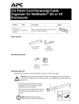
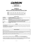
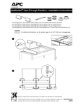
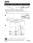
InfraStruXure™ for Wiring Closets and
Computer Rooms: Site Preparation,
Site Planning, and Installation
InfraStruXure for Wiring Closets and Computer rooms is an integrated power, rack, air, and
management architecture consisting of standard, plug-and-play components. This architecture allows
for fast and easy installation, and helps eliminate disorganization within an IT environment by
providing a foundation for your critical IT equipment that fosters organization, ease-of-use, and
control.
This guide summarizes how to install your InfraStruXure System. For detailed installation, operation,
and maintenance instructions, see the documentation included with each component in your system.
Contact your APC representative or visit the APC website (www.apc.com) for a complete list of
InfraStruXure System options and additional documentation.
Before installing or operating any InfraStruXure System components, read the safety instructions and
warnings included in each component’s manual.
This manual is available in English on the enclosed CD.
Dieses Handbuch ist in Deutsch auf der beiliegenden CD-ROM verfügbar.
Este manual está disponible en español en el CD-ROM adjunto.
Ce manuel est disponible en français sur le CD-ROM ci-inclus.
Questo manuale è disponibile in italiano nel CD-ROM allegato.
Deze handleiding staat in het Nederlands op de bijgevoegde cd.
Instrukcja Obslugi w języku polskim jest dostępna na CD.
O manual em Português está disponível no CD-ROM em anexo.
System Components
Rack
NetShelter VX®
Enclosure
NetShelter VX
Open Frame
NetShelter
4-Post Open Frame
NetShelter
2-Post Open Frame
Power
Smart-UPS®
1500 VA, 2200 VA
3000 VA, 5000 VA
Smart-UPS RT
2000 VA, 3000 VA
5000 VA, 7500 VA, 10,000 VA
Symmetra® RM
2–6 kVA
Symmetra LX
4–8 kVA, 8–16 kVA
Power Distribution
Basic
Rack PDUs
Metered
Rack PDUs
Switched
Rack PDUs
InfraStruXure for Wiring Closets and Computer Rooms
3
System Components
Management
InfraStruXure System
Manager
Environmental
Management System
Network
Management Card
Environmental
Monitoring Card
Environmental
Monitoring Unit
Building Management System
Integration Card
Air
NetworkAIR®
Air Distribution Unit
NetworkAIR
Air Removal Unit
Rack accessories
APC offers the following rack accessories for InfraStruXure Systems:
• Stabilization plates and brackets
• Keyboard drawers
• Shielding troughs and cable ladders
• Keyboards
• Blanking panels
• Rack-mounting hardware
• Grounding kits
• Rack fan systems
• Rack PDU mounting brackets
• Security devices
• Shelving
Services †
APC offers the following service packages for InfraStruXure Systems:
• Preventative Maintenance
• Installation and Start-Up Services
• Battery Refresh Programs
• Pre-Installation Consulting
• Network Integration for APC Software
• Extended Warranties
• Remote Monitoring Service
• On-Site Service
†
4
Some services are not available in all areas
InfraStruXure for Wiring Closets and Computer Rooms
Site Preparation
Verify the shipment
Ensure that all labeled pallets and boxes match your purchase order. Do not unpack the pallets and
boxes until you are ready to install the system.
Environmental requirements
Batteries can be permanently damaged if installed in a system that is not being
used. Store battery modules at an ambient temperature below 25° C.
Warning
Select a site that is temperature-controlled, clean, dry, and free of conductive contaminants, and that
meets the following specifications:
Temperature
0 to 40° C
Relative Humidity
0–95% non-condensing
Elevation above mean sea level
0–3000 m
Consider the heat dissipation ratings of equipment to determine cooling requirements. Additional
cooling equipment may be required. For heat dissipation ratings of common InfraStruXure System
UPS types, see the individual UPS product pages on the APC Web site (www.apc.com).
InfraStruXure for Wiring Closets and Computer Rooms
5
Site Preparation
Access and ventilation requirements
Consult your local and national building and fire codes for additional requirements.
457 mm
2527 mm
914 mm
914 mm
Weight considerations
Ensure that the floor and sub-floor can support the total weight of the system concentrated on the
leveling feet of the system’s enclosure. If you are placing equipment on a raised floor, consult the
flooring manufacturer for loading requirements before installing equipment.
Decide what equipment will be installed in your racks and enclosures. Do not exceed the maximum
capacity listed in the table.
6
Rack or Enclosure
Maximum Capacity
NetShelter VX Enclosure
(907 kg)
NetShelter VX Open Frame
(907 kg)
NetShelter 4-Post Open Frame
(454 kg)
NetShelter 2-Post Open Frame
(340 kg)
InfraStruXure for Wiring Closets and Computer Rooms
Site Preparation
Electrical requirements and safety
Consult your UPS and power distribution manuals for detailed electrical
requirements and installation instructions.
Electrical
Hazard
Consult your national and local codes for requirements other than those listed in
the manuals included with your products.
The UPS contains internal batteries and may present a shock hazard even when
disconnected from the branch circuit (mains). See the safety information in your
UPS manual.
Electrical input
Product
Connection
Method
Connection Type
Voltages
Supported
Symmetra RM 2–6 kVA
Hard-wired
40 A, 2-pole (external); #10AWG (6 mm2)
230
Symmetra LX 4–8 kVA
Hard-wired
50 A, 2-pole (external); #6AWG (16 mm²)
230
Symmetra LX 8 –16 kVA Hard-wired
100 A, 2-pole (external); #3AWG (25 mm²) 230
Smart-UPS 1500
Cord-connected
IEC 320 C14
230
Smart-UPS 2200
Cord-connected
IEC 320 C20, Schuko CEE 7/EU1-16P, or
British BS136A
230
Smart-UPS 3000
Cord-connected
IEC 320 C20, Schuko CEE 7/EU1-16P, or
British BS136A
230
Smart-UPS 5000
Hard-wired
3-wire, #10AWG (6 mm2)
230
Smart-UPS RT 2000
Cord-connected
IEC 320 C20, Schuko CEE 7/EU1-16P, or
British BS136A
230
Smart-UPS RT 3000
Cord-connected
IEC 320 C20, Schuko CEE 7/EU1-16P, or
British BS136A
230
Smart-UPS RT 5000
Hard-wired
3-wire, #10AWG (6 mm2)
230
Smart-UPS RT 7500
Hard-wired
50 A, 2-pole, #8AWG (10 mm2), or
50 A, 4-pole, #8AWG (10 mm2)
230
Smart-UPS RT 10000
Hard-wired
63 A, 2-pole, #6AWG (16 mm2), or
63 A, 4-pole, #6AWG (16 mm2)
230
Cord-Connected PDU
Cord-connected
IEC 320 C19
230
InfraStruXure for Wiring Closets and Computer Rooms
7
Site Preparation
Electrical output
8
Voltages
Supported
Product
Connection Type
Symmetra RM 2–6kVA
(8) IEC 320 C13
(2) IEC 320 C19
230
Symmetra LX 4–8kVA
(8) IEC 320 C13
(6) IEC 320 C19
(1) Hard-wired 3-wire (G+N+L1)
230
Symmetra LX 8–16kVA
(8) IEC 320 C13
(10) IEC 320 C19
(1) Hard-wired 3-wire (G+N+L1)
230
Smart-UPS 1500
(4) IEC 320 C13
230
Smart-UPS 2200
(8) IEC 320 C13
(1) IEC 320 C19
230
Smart-UPS 3000
(8) IEC 320 C13
(1) IEC 320 C19
230
Smart-UPS 5000
(8) IEC 320 C13
(2) IEC 320 C19
230
Smart-UPS RT 2000
(6) IEC 320 C13
230
Smart-UPS RT 3000
(8) IEC 320 C13
(2) IEC 320 C19
230
Smart-UPS RT 5000
(8) IEC 320 C13
(2) IEC 320 C19
230
Smart-UPS RT 7500
(4) IEC 320 C13
(4) IEC 320 C19
(1) Hard-wired 3-wire (H+N+G)
230
Smart UPS RT10000
(4) IEC 320 C13
(4) IEC 320 C19
(1) Hard-wired 3-wire (H+N+G)
230
InfraStruXure for Wiring Closets and Computer Rooms
Site Preparation
Emergency Power-Off (EPO)
Electrical
Hazard
A licensed electrician must connect the remote emergency power-off (EPO)
device.
If required by local or national codes, you must connect the EPO (to disable output power in an
emergency) either as internally powered for use with non-powered switch circuits, or externally
powered for use with +24 VDC-powered switch circuits. The EPO circuit must be a Class 2 (UL and
CSA standard) and SELV (IEC standard) circuit, isolated from all primary circuitry.
See the installation istructions included with your UPS for instructions on wiring.
The connection of the UPS to the EPO requires one of the following cable types:
Cable
Description
CL2
Class 2 cable for general use.
CL2P
Plenum cable for use in ducts, plenums, and other spaces used for
environmental air-flow.
CL2R
Riser cable for use in a vertical run in a shaft from floor to floor.
CLEX
Limited use cable for use in dwellings and in raceways.
InfraStruXure for Wiring Closets and Computer Rooms
9
Site Planning
The following are sample configurations you can use to plan the layout of
your computer room. Actual number of racks supported may be less than
shown depending upon the actual load per rack.The clearances shown are the
minimum requirements. Check your local and national codes for additional
requirements.
NetShelterVX
Dimensions
1067 mm
600 mm
Smart-UPS 1500 VA
Supports up to two NetShelter VX enclosures and one UPS.
914 mm
UPS
914 mm
Smart-UPS 2200 VA or 3000 VA
Supports up to three NetShelter VX enclosures and one UPS.
914 mm
UPS
914 mm
Smart-UPS 5000VA or Symmetra RM (2–6 kVA)
Supports up to four NetShelter VX enclosures and one UPS.
914 mm
UPS
914 mm
10
InfraStruXure for Wiring Closets and Computer Rooms
Site Planning
Symmetra LX (4–8 kVA)
Supports four NetShelter VX enclosures, one UPS, and one Rack PDU Extender.
Parallel rows. Set up two short, parallel rows. Run a APC Cable Ladder between the rows.
914 mm
UPS
914 mm
PDU†
914 mm
†Rack
PDU Extender
Adjacent short rows. Set up two short, adjacent rows. Run a APC Cable Ladder between the rows.
914 mm
PDU†
UPS
914 mm
1219 mm
†
Rack PDU Extender
One row. Set up one long row.
914 mm
UPS
914 mm
InfraStruXure for Wiring Closets and Computer Rooms
11
Site Planning
Symmetra LX (8–16 kVA)
Supports eight NetShelter VX enclosures, one UPS, and one Rack PDU Extender.
Parallel rows. Set up two short, parallel rows. Run a APC Cable Ladder between the rows.
914 mm
UPS
914 mm
PDU†
914 mm
† Rack
PDU Extender
Adjacent short rows. Set up two short, adjacent rows. Run a APC Cable Ladder between the rows.
914 mm
UPS
PDU†
1219 mm
†Rack
914 mm
PDU Extender
One row. Set up one long row.
914 mm
UPS
PDU†
914 mm
†
12
Rack PDU Extender
InfraStruXure for Wiring Closets and Computer Rooms
Basic Installation Procedures
Unpack racks and enclosures
Unpack each rack and enclosure included with your shipment according to the unpacking instructions
in the rack or enclosure manual.
Make sure all boxes and packaging are empty before discarding them.
Note
Assemble racks and enclosures
Orient the racks and enclosures in the planned location (see “Site Planning” on page 10), and make
any necessary adjustments to the enclosures that are needed for your location.
If you have enclosures as part of your system. Each row should include one enclosure with
side panels. The other enclosures should be expansion enclosures without side panels.
1. Place the enclosure with side panels
at the end of the row, and remove the
side panel that is adjacent to an
expansion enclosure. Place the side
panel that you removed on the
expansion enclosure at the end of the
row.
2. Join adjacent enclosures.
See also
See the manual included
with your enclosures for
instructions.
InfraStruXure for Wiring Closets and Computer Rooms
13
Basic Installation Procedures
3. Level the enclosures.
Leveling feet are attached under the enclosure at the corners. The leveling feet can help provide
a stable base if the selected floor space is uneven, but cannot compensate for a badly sloped
surface. To level the enclosure:
a. Fit the 14-millimeter end of the open-ended wrench
(provided) to the hex head just above the round pad
on the bottom of a leveling foot. Turn the wrench
clockwise to extend the leveling foot until it makes
firm contact with the floor.
b. Repeat step a for each of the remaining leveling
feet.
c. Use a level to determine which feet need further
adjustment to level the enclosure. Adjust as
necessary.
Install the UPS
Follow the installation procedures in the manual included with your UPS.
See also
Use two people to install the UPS.
Heavy
Install the UPS in the bottom of the selected rack or
enclosure. (See “Site Planning” on page 10 for sample
configurations.) If you have a Symmetra RM UPS or a
Symmetra LX UPS, install the power and battery
modules after you install the UPS in the rack.
Install the Rack PDU Extender
The Rack PDU Extender is used primarily with
the Symmetra LX UPS and the NetShelter VX
Enclosure. It snaps into the base of the
NetShelter VX rear channel, and occupies the
bottom 2U of space behind the rear vertical
mounting rails.
Follow the procedures in the
instruction sheet included with your
See also Rack PDU Extender.
14
InfraStruXure for Wiring Closets and Computer Rooms
Basic Installation Procedures
Install Rack PDUs
See the manual included with your Rack PDUs for detailed safety and installation
instructions.
See also
Install vertical APC Rack PDUs in the rear of a
NetShelter VX Enclosure, in the cable channel
directly behind the rear vertical mounting rails.
You can install the Rack PDU in one of two
ways: using toolless mounting pegs (provided)
or the mounting brackets (sold separately).
Note
You can mount two Rack PDUs on
one side of the enclosure by using
the toolless mounting method.
1. Slide the mounting pegs into the holes
located in the channel in the rear panel of
the enclosure.
2. Snap the Rack PDU into place by pushing
it downward until it locks into position.
Install optional equipment in the enclosures
See the manual included with your optional InfraStruXure equipment for detailed
safety and installation instructions.
See also
InfraStruXure for Wiring Closets and Computer Rooms
15
Basic Connection Procedures
Overview
This section illustrates typical configurations. Your configuration may vary. If you have questions,
consult the user manual of each component, visit the APC Web site (www.apc.com), or contact
Customer Support at a number on the back cover of this manual.
Caution
Do not use only these diagrams to connect your equipment. Read and follow the
safety and connection instructions in the manual included with your UPS and
power distribution equipment.
Smart-UPS 1500VA, 2200VA, 3000 VA
NetShelter VX
Rack PDU
(AP9568)
IEC320-C14 Plug
Smart-UPS 1500VA
User-Supplied Input Power Cord
16
InfraStruXure for Wiring Closets and Computer Rooms
Basic Connection Procedures
Symmetra RM 2–6 kVA UPS
NetShelter VX
Enclosure
Input from Utility (L-N-G)
Rack PDU
(AP7852)
Symmetra RM 2–6 kVA UPS
Symmetra LX 8–16kVA UPS
NetShelter VX
Enclosure
Input from Utility (L-N-G)
Rack PDUs
(AP7852)
Symmetra LX
4–16 kVA UPS
Rack PDU Extender
InfraStruXure for Wiring Closets and Computer Rooms
17
Basic Connection Procedures
Connect Rack PDUs to the UPS
Route the Rack PDU power cords to the UPS
through the bottom of the enclosures, using the
holes in the enclosures’ vertical posts. Plug each
power cord into an outlet on the UPS, or Rack
PDU Extender. The diagram shows vertical Rack
PDUs; however, you can use any APC Rack PDUs
with plugs that match your UPS outlets, or Rack
PDU Extender outlets. See “Electrical
requirements and safety” on page 7 for
information on the outlet type of each UPS.
Connect UPS Batteries
The Smart-UPS models are shipped with the batteries installed; however, you must make the
necessary connections to energize the batteries before the UPS will operate.
Ensure that the battery modules in the Symmetra RM or Symmetra LX UPS are seated properly.
See the manual included with your UPS for detailed safety and installation
instructions.
See also
Configure APC management devices
Your InfraStruXure System can be managed through the APC Network Management Card or through
the InfraStruXure System Manager.
If you have an InfraStruXure System Manager as part of your system, connect each Network
Management card to the InfraStruXure System Manager hub using CAT5 network cables, and
configure the InfraStruXure System Manager.
See also
See the manual included with your InfraStruXure System Manager for quick
configuration instructions, and see the on-line help on the InfraStruXure System
Manager’s interface for more information on managing the system.
If you do not have an InfraStruXure System Manager as part of your system, configure the network
settings of each Network Management card in your system.
See also
18
See the manual included with your Network Management Card for quick configuration
instructions and the supporting documentation on the CD for more detailed
information.
InfraStruXure for Wiring Closets and Computer Rooms
Warranty
InfraStruXure Standard Warranty
APC warrants that all components of the InfraStruXure system will be free from defect in material
and workmanship for a period of two years from the date of start up when start up has been
performed by APC authorized service personnel*. If assembly services are included in the original
purchase and are also performed by APC authorized service personnel, APC offers an additional year
of warranty at no additional charge. In the event that the system fails to meet the forgoing warranty,
APC shall repair or replace, at its sole discretion, any such defective parts. Under this warranty, APC
will ship all parts to your site at no cost to be available for you the next business day after APC is
notified of this requirement. If you choose to upgrade the system to include an on site contract, APC
offers modular service packages to match your needs.
Each point product incorporated into the system has a separate factory warranty that is applied when
sold as a standalone unit. When incorporated into an InfraStruXure solution, the unit will be covered
by the InfraStruXure warranty. In cases where one warranty favors the customer over the other, the
stronger of the two warranties will take precedence.
*All warranties are null and void unless installation and startup are performed by authorized APC
Global Services service centers.
APC shall not be liable under this warranty if its testing and examination disclose that the
alleged defect in the product does not exist or was caused by purchaser’s or any third person’s
misuse, negligence, improper installation or testing, unauthorized attempts to repair or modify,
or any other cause beyond the range of the intended use, or by accident, fire, lightening or other
hazard.
There are no waranties, express or implied, by operation of law or otherwise, of products sold,
serviced or furnished under this agreement or in connection herewith. APC disclams all
implied warranties of merchantability, satisfaction and fitness for a particular purpose. APC’s
express warranties will not be enlarged, diminished, or affected by and no obligation or liability
will arise out of, APC’s rendering of technical or other advice or service in connection with the
products. The foregoing waranties and remedies are exclusive and in lieu of all other
warranties and remedies. The warranties set fourth above constitute APC’s sole liability and
purchaser exclusive remedy for any breach of such warranties. APC’s warranties run only to
purchaser and are not extended to any third parties. In no event shall APC, its officers,
directors, affiliates or employees be liable for any form of indirect, special consequental or
punitive damages, arising out of the use, service or installation, of the products, whether such
damages arise in contract or tort, irrespective of fault, negligence or strict liability or whether
APC has been advised in advance of the possibility of such damages.
InfraStruXure for Wiring Closets and Computer Rooms
19
®
APC Worldwide Customer Support
Customer support for this or any other APC product is available at no charge in any of the following ways:
• Visit the APC Web site to access documents in the APC Knowledge Base and to submit customer support
requests.
– www.apc.com (Corporate Headquarters)
Connect to localized APC Web sites for specific countries, each of which provides customer support
information.
– www.apc.com/support/
Global support searching APC Knowledge Base and using e-support.
• Contact an APC Customer Support center by telephone or e-mail.
– Regional centers:
Direct InfraStruXure Customer Support Line
(1)(877)537-0607 (toll free)
APC headquarters U.S., Canada
(1)(800)800-4272 (toll free)
Latin America
(1)(401)789-5735 (USA)
Europe, Middle East, Africa
(353)(91)702000 (Ireland)
Japan
(0) 35434-2021
Australia, New Zealand, South Pacific area
(61) (2) 9955 9366 (Australia)
– Local, country-specific centers: go to www.apc.com/support/contact for contact information.
Contact the APC representative or other distributor from whom you purchased your APC product for information on
how to obtain local customer support.
Entire contents copyright © 2004 American Power Conversion. All rights reserved. Reproduction in
whole or in part without permission is prohibited. APC, the APC logo, InfraStruXure, NetShelter,
NetworkAIR, Smart-UPS, and Symmetra are trademarks of American Power Conversion Corporation
and may be registered in some jurisdictions. All other trademarks, product names, and corporate
names are the property of their respective owners and are used for informational purposes only.
990-1681-001
*990-1681-001*
09/2004