1
GTX Radios
Radio Service Software
User's Guide
© 1998 - 1999 by Motorola, Inc.,
Radio Products Group
8000 W. Sunrise Blvd., Ft. Lauderdale, FL 33322
Printed in U.S.A. 2/99. All Rights Reserved.
68P02948C70-B
COMPATIBILITY NOTICE
This version of the Radio Service Software (RSS) incorporates changes made to the GTX radio codeplug with
regard to additions to the GTX radio “Basic” model family.
These changes are not backward compatible with previous versions of the GTX RSS. This version of the RSS
will properly read all current codeplug archive files and radio codeplugs. However, codeplugs that are written
with this version will not be readable by prior RSS versions.
The changes are transparent to the radio’s firmware. Therefore, the changes are compatible with all current/
prior radio firmware versions.
Use caution if you are distributing this version among several service locations to ensure that all locations
begin use of this version at the same time.
COMPUTER SOFTWARE COPYRIGHTS
The Motorola® products described in this manual may include copyrighted Motorola computer programs
stored in semiconductor memories or other media. Laws in the United States and other countries preserve for
Motorola certain rights for copyrighted computer programs, including the exclusive right to copy or reproduce
in any form the copyrighted computer program. Accordingly, any copyrighted Motorola computer programs
contained in the Motorola products described in this manual may not be copied without the express written
permission of Motorola. Furthermore, the purchase of Motorola products shall not be deemed to grant either
directly or by implication, estoppel, or otherwise, any license under the copyrights, patents or patent applications of Motorola, except for the normal non-exclusive, royalty-free license to use that arises by operation
of law in the sale of a product.
Motorola, Privacy Plus, Private Conversation,
Call Alert, Private-Line, Digital Private-Line, and Private Conversation are trademarks of Motorola Inc.
IBM is a registered trademark of International Business Machines Inc.
LTR ® is a registered trademark of the E.F.Johnson Company.
© 1987 -1999 by Motorola, Inc., Radio Products Group
8000 West Sunrise Blvd., Ft. Lauderdale, FL 33322
Printed in U.S.A.01/99. All Rights Reserved.
C
GTX/LTR Radios
Radio Service Software
User’s Guide
Table of Contents
1.0 INTRODUCTION . . . . . . . . . . . . . . . . . . . . . . . . . . . . . . . . . . . . . . . . . . . . . . . . . . . . . . . . . . . . . . . . . . . . 1
1.1 Application. . . . . . . . . . . . . . . . . . . . . . . . . . . . . . . . . . . . . . . . . . . . . . . . . . . . . . . . . . . . . . . . . . . . . . 1
1.2 Programming Kit . . . . . . . . . . . . . . . . . . . . . . . . . . . . . . . . . . . . . . . . . . . . . . . . . . . . . . . . . . . . . . . . . 2
1.3 Required Hardware . . . . . . . . . . . . . . . . . . . . . . . . . . . . . . . . . . . . . . . . . . . . . . . . . . . . . . . . . . . . . . . 2
2.0 GETTING STARTED. . . . . . . . . . . . . . . . . . . . . . . . . . . . . . . . . . . . . . . . . . . . . . . . . . . . . . . . . . . . . . . . . 3
2.1 How This Manual Is Organized . . . . . . . . . . . . . . . . . . . . . . . . . . . . . . . . . . . . . . . . . . . . . . . . . . . . . . 3
2.2 Connecting the Radio to the Computer. . . . . . . . . . . . . . . . . . . . . . . . . . . . . . . . . . . . . . . . . . . . . . . . 3
2.3 How to Read the Screens . . . . . . . . . . . . . . . . . . . . . . . . . . . . . . . . . . . . . . . . . . . . . . . . . . . . . . . . . . 5
2.4 How to Use the Keyboard . . . . . . . . . . . . . . . . . . . . . . . . . . . . . . . . . . . . . . . . . . . . . . . . . . . . . . . . . . 6
2.5 How the Screens are Organized . . . . . . . . . . . . . . . . . . . . . . . . . . . . . . . . . . . . . . . . . . . . . . . . . . . . . 7
2.6 How To Install the Software . . . . . . . . . . . . . . . . . . . . . . . . . . . . . . . . . . . . . . . . . . . . . . . . . . . . . . . . 8
A. Hard Disk Installation . . . . . . . . . . . . . . . . . . . . . . . . . . . . . . . . . . . . . . . . . . . . . . . . . . . . . . . . . . . 8
2.7 How To Configure the Software for Your Computer . . . . . . . . . . . . . . . . . . . . . . . . . . . . . . . . . . . . . . 9
2.8 The MAIN MENU . . . . . . . . . . . . . . . . . . . . . . . . . . . . . . . . . . . . . . . . . . . . . . . . . . . . . . . . . . . . . . . 13
3.0 SERVICING THE RADIO . . . . . . . . . . . . . . . . . . . . . . . . . . . . . . . . . . . . . . . . . . . . . . . . . . . . . . . . . . . . 15
3.1 Alignment . . . . . . . . . . . . . . . . . . . . . . . . . . . . . . . . . . . . . . . . . . . . . . . . . . . . . . . . . . . . . . . . . . . . . 17
3.1.1 Transmitter Deviation . . . . . . . . . . . . . . . . . . . . . . . . . . . . . . . . . . . . . . . . . . . . . . . . . . . . . . . 18
3.1.2 Reference Oscillator Warp . . . . . . . . . . . . . . . . . . . . . . . . . . . . . . . . . . . . . . . . . . . . . . . . . . . 19
3.1.3 Transmitter Power. . . . . . . . . . . . . . . . . . . . . . . . . . . . . . . . . . . . . . . . . . . . . . . . . . . . . . . . . . 20
3.1.4 Squelch . . . . . . . . . . . . . . . . . . . . . . . . . . . . . . . . . . . . . . . . . . . . . . . . . . . . . . . . . . . . . . . . . 21
3.2 Board Replacement/Repair. . . . . . . . . . . . . . . . . . . . . . . . . . . . . . . . . . . . . . . . . . . . . . . . . . . . . . . . 22
3.2.1 Logic or RF Board Replacement . . . . . . . . . . . . . . . . . . . . . . . . . . . . . . . . . . . . . . . . . . . . . . 23
3.2.2 Transmitter Power Calibration Procedure . . . . . . . . . . . . . . . . . . . . . . . . . . . . . . . . . . . . . . . 24
3.2.3 TX Deviation Calibration . . . . . . . . . . . . . . . . . . . . . . . . . . . . . . . . . . . . . . . . . . . . . . . . . . . . 25
4.0 GET/SAVE CODEPLUG DATA. . . . . . . . . . . . . . . . . . . . . . . . . . . . . . . . . . . . . . . . . . . . . . . . . . . . . . . . 27
4.1 Read Codeplug . . . . . . . . . . . . . . . . . . . . . . . . . . . . . . . . . . . . . . . . . . . . . . . . . . . . . . . . . . . . . . . . . 28
4.2 Get File . . . . . . . . . . . . . . . . . . . . . . . . . . . . . . . . . . . . . . . . . . . . . . . . . . . . . . . . . . . . . . . . . . . . . . . 29
4.3 Get Standard File . . . . . . . . . . . . . . . . . . . . . . . . . . . . . . . . . . . . . . . . . . . . . . . . . . . . . . . . . . . . . . . 31
4.4 Clone Radio. . . . . . . . . . . . . . . . . . . . . . . . . . . . . . . . . . . . . . . . . . . . . . . . . . . . . . . . . . . . . . . . . . . . . . . 33
4.4.1 Limited Clone . . . . . . . . . . . . . . . . . . . . . . . . . . . . . . . . . . . . . . . . . . . . . . . . . . . . . . . . . . . . . 34
4.4.2 Clone Codeplug . . . . . . . . . . . . . . . . . . . . . . . . . . . . . . . . . . . . . . . . . . . . . . . . . . . . . . . . . . . 35
4.4.3 Radio Upgrade Configuration . . . . . . . . . . . . . . . . . . . . . . . . . . . . . . . . . . . . . . . . . . . . . . . . 38
4.5 .Save File . . . . . . . . . . . . . . . . . . . . . . . . . . . . . . . . . . . . . . . . . . . . . . . . . . . . . . . . . . . . . . . . . . . . . 37
4.5.1 Backup File. . . . . . . . . . . . . . . . . . . . . . . . . . . . . . . . . . . . . . . . . . . . . . . . . . . . . . . . . . . . . . . 38
4.6 Program Codeplug . . . . . . . . . . . . . . . . . . . . . . . . . . . . . . . . . . . . . . . . . . . . . . . . . . . . . . . . . . . . . . 39
5.0 CHANGE/VIEW . . . . . . . . . . . . . . . . . . . . . . . . . . . . . . . . . . . . . . . . . . . . . . . . . . . . . . . . . . . . . . . . . . 41
5.1 Change/view Radio-wide Configuration . . . . . . . . . . . . . . . . . . . . . . . . . . . . . . . . . . . . . . . . . . . . . 43
5.1.1 Scan And Roam Configuration . . . . . . . . . . . . . . . . . . . . . . . . . . . . . . . . . . . . . . . . . . . . . . . 45
5.1.1.1 Talkgroup Scan List . . . . . . . . . . . . . . . . . . . . . . . . . . . . . . . . . . . . . . . . . . . . . . . . . . . 47
5.1.2 Change/view Phone List . . . . . . . . . . . . . . . . . . . . . . . . . . . . . . . . . . . . . . . . . . . . . . . . . . . . 48
5.1.3 Change/view Dtmf Options . . . . . . . . . . . . . . . . . . . . . . . . . . . . . . . . . . . . . . . . . . . . . . . . . . 49
5.1.4 Scan And Roam Configuration (Ltr) . . . . . . . . . . . . . . . . . . . . . . . . . . . . . . . . . . . . . . . . . . . 50
5.1.5 Change/view Phone List (Ltr) . . . . . . . . . . . . . . . . . . . . . . . . . . . . . . . . . . . . . . . . . . . . . . . . 51
5.1.6 Change/view Dtmf Options (Ltr) . . . . . . . . . . . . . . . . . . . . . . . . . . . . . . . . . . . . . . . . . . . . . . 52
i
TABLE OF CONTENTS (cont.)
5.2 Change/view Mode Configuration . . . . . . . . . . . . . . . . . . . . . . . . . . . . . . . . . . . . . . . . . . . . . . . . . . 53
5.2.1 Change/view Trunked Mode . . . . . . . . . . . . . . . . . . . . . . . . . . . . . . . . . . . . . . . . . . . . . . . . . 53
5.2.2 Change/view Conventional Mode . . . . . . . . . . . . . . . . . . . . . . . . . . . . . . . . . . . . . . . . . . . . . 55
5.2.3 Ltr Trunking . . . . . . . . . . . . . . . . . . . . . . . . . . . . . . . . . . . . . . . . . . . . . . . . . . . . . . . . . . . . . . 58
5.2.3.1 Site Access Setup . . . . . . . . . . . . . . . . . . . . . . . . . . . . . . . . . . . . . . . . . . . . . . . . . . . . 59
5.2.3.2 Universal Id Features . . . . . . . . . . . . . . . . . . . . . . . . . . . . . . . . . . . . . . . . . . . . . . . . . 60
5.2.3.3 Group Number Features . . . . . . . . . . . . . . . . . . . . . . . . . . . . . . . . . . . . . . . . . . . . . . . 61
5.2.3.4 Radio Site Blocks . . . . . . . . . . . . . . . . . . . . . . . . . . . . . . . . . . . . . . . . . . . . . . . . . . . . 62
5.2.3.5 Site Utility Screen . . . . . . . . . . . . . . . . . . . . . . . . . . . . . . . . . . . . . . . . . . . . . . . . . . . . 63
5.3 Trunking Personality Configuration . . . . . . . . . . . . . . . . . . . . . . . . . . . . . . . . . . . . . . . . . . . . . . . . . 64
5.3.1 Trunking System Configuration . . . . . . . . . . . . . . . . . . . . . . . . . . . . . . . . . . . . . . . . . . . . . . . 67
5.3.2 Trunking Personality Options . . . . . . . . . . . . . . . . . . . . . . . . . . . . . . . . . . . . . . . . . . . . . . . . . 70
5.3.3 Trunking Lists . . . . . . . . . . . . . . . . . . . . . . . . . . . . . . . . . . . . . . . . . . . . . . . . . . . . . . . . . . . . 72
5.3.3.1 Announcement Talkgroup List (Type Ii Only) . . . . . . . . . . . . . . . . . . . . . . . . . . . . . . . . 73
5.3.3.2 Trunking Private Call List . . . . . . . . . . . . . . . . . . . . . . . . . . . . . . . . . . . . . . . . . . . . . . . 74
5.4 Utilities . . . . . . . . . . . . . . . . . . . . . . . . . . . . . . . . . . . . . . . . . . . . . . . . . . . . . . . . . . . . . . . . . . . . . . . 76
5.4.1 Add Mode . . . . . . . . . . . . . . . . . . . . . . . . . . . . . . . . . . . . . . . . . . . . . . . . . . . . . . . . . . . . . . . 78
5.4.2 Delete Mode . . . . . . . . . . . . . . . . . . . . . . . . . . . . . . . . . . . . . . . . . . . . . . . . . . . . . . . . . . . . . 80
5.4.3 Move Mode . . . . . . . . . . . . . . . . . . . . . . . . . . . . . . . . . . . . . . . . . . . . . . . . . . . . . . . . . . . . . . 81
5.4.4 Delete Personality . . . . . . . . . . . . . . . . . . . . . . . . . . . . . . . . . . . . . . . . . . . . . . . . . . . . . . . . . 83
5.4.5 Move Personality . . . . . . . . . . . . . . . . . . . . . . . . . . . . . . . . . . . . . . . . . . . . . . . . . . . . . . . . . . 84
6.0 PRINT . . . . . . . . . . . . . . . . . . . . . . . . . . . . . . . . . . . . . . . . . . . . . . . . . . . . . . . . . . . . . . . . . . . . . . . . . . 85
7.0 APPENDIX. . . . . . . . . . . . . . . . . . . . . . . . . . . . . . . . . . . . . . . . . . . . . . . . . . . . . . . . . . . . . . . . . . . . . . . 87
7.1 Error Messages . . . . . . . . . . . . . . . . . . . . . . . . . . . . . . . . . . . . . . . . . . . . . . . . . . . . . . . . . . . . . . . . 87
7.2 How To Restore Archive Files From Backup Disks. . . . . . . . . . . . . . . . . . . . . . . . . . . . . . . . . . . . . 90
7.3 Archive File Structure . . . . . . . . . . . . . . . . . . . . . . . . . . . . . . . . . . . . . . . . . . . . . . . . . . . . . . . . . . . 92
7.4 Program File Organization. . . . . . . . . . . . . . . . . . . . . . . . . . . . . . . . . . . . . . . . . . . . . . . . . . . . . . . . 93
7.5 How To Format A Disk . . . . . . . . . . . . . . . . . . . . . . . . . . . . . . . . . . . . . . . . . . . . . . . . . . . . . . . . . . 94
GLOSSARY . . . . . . . . . . . . . . . . . . . . . . . . . . . . . . . . . . . . . . . . . . . . . . . . . . . . . . . . . . . . . . . . . . . . . . . . . . 95
ACRONYMS AND ABBREVIATIONS . . . . . . . . . . . . . . . . . . . . . . . . . . . . . . . . . . . . . . . . . . . . . . . . . . . . . . 99
RSS USER'S GUIDE QUESTIONNAIRE . . . . . . . . . . . . . . . . . . . . . . . . . . . . . . . . . . . . . . . . . back of manual
LIST OF FIGURES
FIGURE
2-1
2-2
2-3
2-4
2-5
2-6
2-7
3-1
3-2
3-3
3-4
3-5
3-6
ii
TITLE
PAGE
Radio-RIB-Computer Configuration. . . . . . . . . . . . . . . . . . . . . . . . . . . . . . . . . . . . . . . . . . . . . . . 4
Sample Screen . . . . . . . . . . . . . . . . . . . . . . . . . . . . . . . . . . . . . . . . . . . . . . . . . . . . . . . . . . . . . . 5
Radio Service Software Organization . . . . . . . . . . . . . . . . . . . . . . . . . . . . . . . . . . . . . . . . . . . . . 7
Service Software Configuration Menu . . . . . . . . . . . . . . . . . . . . . . . . . . . . . . . . . . . . . . . . . . . . 9
Configure Computer Screen . . . . . . . . . . . . . . . . . . . . . . . . . . . . . . . . . . . . . . . . . . . . . . . . . . . 10
Configure Screen. . . . . . . . . . . . . . . . . . . . . . . . . . . . . . . . . . . . . . . . . . . . . . . . . . . . . . . . . . . . 12
The MAIN Menu . . . . . . . . . . . . . . . . . . . . . . . . . . . . . . . . . . . . . . . . . . . . . . . . . . . . . . . . . . . . 13
Service Menu . . . . . . . . . . . . . . . . . . . . . . . . . . . . . . . . . . . . . . . . . . . . . . . . . . . . . . . . . . . . . . 15
Service Screens Organization . . . . . . . . . . . . . . . . . . . . . . . . . . . . . . . . . . . . . . . . . . . . . . . . . . 16
Alignment Menu. . . . . . . . . . . . . . . . . . . . . . . . . . . . . . . . . . . . . . . . . . . . . . . . . . . . . . . . . . . . . 17
Transmitter Deviation Adjustment . . . . . . . . . . . . . . . . . . . . . . . . . . . . . . . . . . . . . . . . . . . . . . . 18
Reference Oscillator Warp Adjustment . . . . . . . . . . . . . . . . . . . . . . . . . . . . . . . . . . . . . . . . . . . 19
Transmitter Power Adjustment . . . . . . . . . . . . . . . . . . . . . . . . . . . . . . . . . . . . . . . . . . . . . . . . . . 20
LIST OF FIGURES (cont.
FIGURE
TITLE
3-7
3-8
3-9
3-10
3-11
3-12
4-1
4-2
4-3
4-4
4-5
4-6
4-7
4-8
4-9
4-10
4-11
5-1
5-2
5-3
5-4
5-5
5-6
5-7
5-8
5-9
5-10
5-11
5-12
5-13
5-14
5-15
5-16
5-17
5-18
5-19
5-20
5-21
5-22
5-23
5-24
5-25
5-26
5-27
5-28
5-29
Portable Squelch Attenuator . . . . . . . . . . . . . . . . . . . . . . . . . . . . . . . . . . . . . . . . . . . . . . . . . . .
Board Replacement Menu . . . . . . . . . . . . . . . . . . . . . . . . . . . . . . . . . . . . . . . . . . . . . . . . . . . .
Logic Board Replacement . . . . . . . . . . . . . . . . . . . . . . . . . . . . . . . . . . . . . . . . . . . . . . . . . . . . .
Transmitter Power Calibration . . . . . . . . . . . . . . . . . . . . . . . . . . . . . . . . . . . . . . . . . . . . . . . . . .
TX Deviation Calibration (1 of 2) . . . . . . . . . . . . . . . . . . . . . . . . . . . . . . . . . . . . . . . . . . . . . . . .
TX Deviation Calibration (2 of 2) . . . . . . . . . . . . . . . . . . . . . . . . . . . . . . . . . . . . . . . . . . . . . . . .
GET/SAVE Menu . . . . . . . . . . . . . . . . . . . . . . . . . . . . . . . . . . . . . . . . . . . . . . . . . . . . . . . . . . .
Read Codeplug . . . . . . . . . . . . . . . . . . . . . . . . . . . . . . . . . . . . . . . . . . . . . . . . . . . . . . . . . . . . .
Get Archive File . . . . . . . . . . . . . . . . . . . . . . . . . . . . . . . . . . . . . . . . . . . . . . . . . . . . . . . . . . . . .
Get Standard File . . . . . . . . . . . . . . . . . . . . . . . . . . . . . . . . . . . . . . . . . . . . . . . . . . . . . . . . . . .
Standard File Merge . . . . . . . . . . . . . . . . . . . . . . . . . . . . . . . . . . . . . . . . . . . . . . . . . . . . . . . . .
Clone Radio Menu . . . . . . . . . . . . . . . . . . . . . . . . . . . . . . . . . . . . . . . . . . . . . . . . . . . . . . . . . .
Limited Clone . . . . . . . . . . . . . . . . . . . . . . . . . . . . . . . . . . . . . . . . . . . . . . . . . . . . . . . . . . . . . .
Clone Codeplug. . . . . . . . . . . . . . . . . . . . . . . . . . . . . . . . . . . . . . . . . . . . . . . . . . . . . . . . . . . . .
Save File . . . . . . . . . . . . . . . . . . . . . . . . . . . . . . . . . . . . . . . . . . . . . . . . . . . . . . . . . . . . . . . . . .
File Backup . . . . . . . . . . . . . . . . . . . . . . . . . . . . . . . . . . . . . . . . . . . . . . . . . . . . . . . . . . . . . . . .
Program Codeplug . . . . . . . . . . . . . . . . . . . . . . . . . . . . . . . . . . . . . . . . . . . . . . . . . . . . . . . . . .
Change/View Menu . . . . . . . . . . . . . . . . . . . . . . . . . . . . . . . . . . . . . . . . . . . . . . . . . . . . . . . . .
Change/View Screens . . . . . . . . . . . . . . . . . . . . . . . . . . . . . . . . . . . . . . . . . . . . . . . . . . . . . . .
Radio Wide Configuration . . . . . . . . . . . . . . . . . . . . . . . . . . . . . . . . . . . . . . . . . . . . . . . . . . . . .
Scan and Roam Configuration . . . . . . . . . . . . . . . . . . . . . . . . . . . . . . . . . . . . . . . . . . . . . . . . .
Talkgroup Scan List . . . . . . . . . . . . . . . . . . . . . . . . . . . . . . . . . . . . . . . . . . . . . . . . . . . . . . . . .
Phone List . . . . . . . . . . . . . . . . . . . . . . . . . . . . . . . . . . . . . . . . . . . . . . . . . . . . . . . . . . . . . . . . .
Phone Options . . . . . . . . . . . . . . . . . . . . . . . . . . . . . . . . . . . . . . . . . . . . . . . . . . . . . . . . . . . . .
Scan and Roam Configuration . . . . . . . . . . . . . . . . . . . . . . . . . . . . . . . . . . . . . . . . . . . . . . . . .
Phone List . . . . . . . . . . . . . . . . . . . . . . . . . . . . . . . . . . . . . . . . . . . . . . . . . . . . . . . . . . . . . . . .
Phone Options . . . . . . . . . . . . . . . . . . . . . . . . . . . . . . . . . . . . . . . . . . . . . . . . . . . . . . . . . . . . .
Trunking Mode Configuration . . . . . . . . . . . . . . . . . . . . . . . . . . . . . . . . . . . . . . . . . . . . . . . . . .
Conventional Mode Configuration . . . . . . . . . . . . . . . . . . . . . . . . . . . . . . . . . . . . . . . . . . . . . .
LTR Trunking Mode Configuration . . . . . . . . . . . . . . . . . . . . . . . . . . . . . . . . . . . . . . . . . . . . . . .
Radio Site Access Blocks . . . . . . . . . . . . . . . . . . . . . . . . . . . . . . . . . . . . . . . . . . . . . . . . . . . . .
Radio Site Blocks . . . . . . . . . . . . . . . . . . . . . . . . . . . . . . . . . . . . . . . . . . . . . . . . . . . . . . . . . . .
Site Utility Screen . . . . . . . . . . . . . . . . . . . . . . . . . . . . . . . . . . . . . . . . . . . . . . . . . . . . . . . . . . .
Trunking Personality Configuration . . . . . . . . . . . . . . . . . . . . . . . . . . . . . . . . . . . . . . . . . . . . . .
Trunking System Configuration . . . . . . . . . . . . . . . . . . . . . . . . . . . . . . . . . . . . . . . . . . . . . . . .
Trunking Personality Options . . . . . . . . . . . . . . . . . . . . . . . . . . . . . . . . . . . . . . . . . . . . . . . . . .
Trunking Lists Menu . . . . . . . . . . . . . . . . . . . . . . . . . . . . . . . . . . . . . . . . . . . . . . . . . . . . . . . . .
Announcement Talkgroup List . . . . . . . . . . . . . . . . . . . . . . . . . . . . . . . . . . . . . . . . . . . . . . . . .
Trunking Call List . . . . . . . . . . . . . . . . . . . . . . . . . . . . . . . . . . . . . . . . . . . . . . . . . . . . . . . . . . .
Mode List. . . . . . . . . . . . . . . . . . . . . . . . . . . . . . . . . . . . . . . . . . . . . . . . . . . . . . . . . . . . . . . . . .
Add Conventional Mode . . . . . . . . . . . . . . . . . . . . . . . . . . . . . . . . . . . . . . . . . . . . . . . . . . . . . .
Add Trunking Mode . . . . . . . . . . . . . . . . . . . . . . . . . . . . . . . . . . . . . . . . . . . . . . . . . . . . . . . . . .
Delete Mode . . . . . . . . . . . . . . . . . . . . . . . . . . . . . . . . . . . . . . . . . . . . . . . . . . . . . . . . . . . . . . .
Move Mode . . . . . . . . . . . . . . . . . . . . . . . . . . . . . . . . . . . . . . . . . . . . . . . . . . . . . . . . . . . . . . . .
Delete Personality . . . . . . . . . . . . . . . . . . . . . . . . . . . . . . . . . . . . . . . . . . . . . . . . . . . . . . . . . .
Move Personality . . . . . . . . . . . . . . . . . . . . . . . . . . . . . . . . . . . . . . . . . . . . . . . . . . . . . . . . . . .
21
22
23
24
25
26
27
28
29
31
32
33
34
35
37
38
39
41
42
43
45
47
48
49
50
51
52
53
55
58
59
62
63
64
67
70
72
73
74
76
78
79
80
81
83
84
6-1
Print Menu . . . . . . . . . . . . . . . . . . . . . . . . . . . . . . . . . . . . . . . . . . . . . . . . . . . . . . . . . . . . . . . . . 89
iii
LIST OF TABLES
TABLE
A-1
A-2
A-3
iv
TITLE
PAGE
Radio/Computer Interface Errors. . . . . . . . . . . . . . . . . . . . . . . . . . . . . . . . . . . . . . . . . . . . . . . . 92
Computer System Errors . . . . . . . . . . . . . . . . . . . . . . . . . . . . . . . . . . . . . . . . . . . . . . . . . . . . . . 93
DBF File Structure . . . . . . . . . . . . . . . . . . . . . . . . . . . . . . . . . . . . . . . . . . . . . . . . . . . . . . . . . . . 96
1.0
INTRODUCTION
1.1
APPLICATION
The GTX Radios contain a new generation of advanced integrated circuits, with all RF and signalling parameters controlled by the radio’s microprocessor. This Radio Service Software package is required to perform all
alignment adjustments. The GTX radios do not contain any internal adjustable components (i.e. coils, pots,
etc.).
This software also permits programming of all conventional and some trunking features, viewing of all trunking
controlled parameters, and contains some helpful service aids for troubleshooting purposes.
The Motorola GTX Radio Service Software (RSS) Privacy Plus/LTR currently supports these models:
10-Trunk Systems x 8-Groups/System (80 trunked modes, 10 conventional channels):
‘Standard’ full-featured models. Portables have keypad and display
GTX/Privacy Plus Mobile
M11UGD6CB1_N
800 MHz, 15 Watt
GTX/Privacy Plus Mobile
M11WGD4CB1_N
900 MHz, 12 Watt
GTX/Privacy Plus Portable
H11UCD6CB1_N
800 MHz, 3 Watt
GTX/Privacy Plus Portable
H11WCD4CB1_N
900 MHz, 3 Watt
GTX/LTR Mobile
M11UGD6CU1_N
800 MHz, 15 Watt
GTX/LTR Mobile
M11WGD4CU1_N
900 MHz, 12 Watt
GTX/LTR Portable
H11UCD6CU1_N
800 MHz, 3 Watt
GTX/LTR Portable
H11WCD4CU1_N
900 MHz, 3 Watt
4-Trunk Systems x 3-Groups/System (12 trunked modes, 4 conventional channels):
‘Basic’ models. Portables have no keypad or display
GTX/Privacy Plus Portable
H11UCC6DB1_N
800 MHz, 3 Watt
GTX/Privacy Plus Portable
H11WCC4DB1_N
900 MHz, 3 Watt
GTX/LTR Portable
H11UCC6DU1_N
800 MHz, 3 Watt
GTX/LTR Portable
H11WCC4DU1_N
900 MHz, 3 Watt
IMPORTANT
It is the responsibility of the user not to violate any FCC regulations or authorizations covering
the operation of any Motorola product.
INTRODUCTION
1
1.2
PROGRAMMING KIT
The programming kit consists of the application software and this manual. The software is
available in 3 1/2-inch disk format:
RSS for GTX
1.3
KIT NUMBER
RVN-4150E
Disk Format
3 1/2-inch diskettes
REQUIRED HARDWARE
In addition to the application software, the following hardware is required to communicate with the radio:
2
1-
IBM PC, AT Personal Computer, or IBM Personal System 2, Model 25/30/50/60/70/80
equipped with 640K byte available RAM (minimum), an RS-232 Asynchronous Serial
Communications Adapter, and DOS 3.2 or higher. A computer with a hard disk is required
to run the program.
2-
Radio Interface Box (RIB)
3-
RIB Power Supply
4-
RIB to IBM PC/XT interface cable (25-pin)
RIB to IBM AT interface cable (9-pin)
01-80357A57 (110v)
01-80358A56 (220v)
60-82728J01 (9v)
30-80369B71
30-80369B72
5-
RIB to radio interface cable (mobile)
30-80070N01
6-
Mobile radio power cable (10/15 Watt)
(20/25/35 Watt)GKN6270
7-
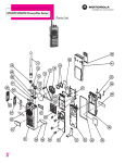
Portable radio programmer assembly
HKN9857
PART NUMBER
RLN-4008
INTRODUCTION
2.0
GETTING STARTED
2.1
HOW THIS MANUAL IS ORGANIZED
This section, GETTING STARTED, describes how to connect the radio to your computer and how to install the
software. It includes how to read the screens, how to use the keyboard, how the screens are organized, and
how to configure the software for your computer. It also includes description of the main menu and its functions available via the main menu. The following three sections provide information on SERVICING THE
RADIO, GETTING and SAVING radio codeplug data, CHANGING and VIEWING codeplug data, and PRINTING radio configurations. All Radio Service Software (RSS) screens are included in this manual with detailed
descriptions of each data field. An APPENDIX includes description of error codes, database structure format,
and summary of the program organization and the keyboard commands.
2.2
CONNECTING THE RADIO TO THE COMPUTER
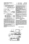
The radio and the Radio Interface Box (RIB) should be connected to the computer as described below and
shown in Figure 2-1.
1.
Connect the RIB-to-IBM interface cable end marked “TO IBM” to one of the computer’s serial
communications ports (either COM1 or COM2). Refer to your computer owner’s manual for the
location of the serial ports. Next, connect the other end marked “TO RIB” to the 15-pin connector
on the RIB.
2.
Connect the RIB-to-Radio interface cable end marked “TO RIB” to the 25-pin connector on
the RIB. Connect the telephone modular connector to the microphone jack of the radio.
Portable Models:
Connect radio to the HKN9857A programming cable. Connect 25-pin, D-type connector to the RIB.
Connect dual banana connector of HKN9857 to a 7.5 VDC power supply (red to +, black to -).
Mobile Models:
Connect the radio power cable leads (black to the negative (-) terminal and red to the positive (+)
terminal) to a power supply and connect the connector end of the power cable to the radio. The power
supply should be set at a nominal voltage of 13.6 Vdc for mobile models, and 7.5V for portable
models.
3.
Take the RIB power supply and connect it to the RIB. Plug the RIB power supply transformer
into an AC outlet. (NOTE: RIB power supply not required for RLN-4008).
4.
The radio will be ready to communicate with the computer once power is applied and the
application software is started.
GETTING STARTED
3
IBM PC
RIB Power Supply
01-80357A57 (110V)
01-80358A56 (220V)
60-82728J01 (9V)
Computer Interface Cable
30-80369B71 (25 pin) or
30-80369B72 (9 pin)
(3-1/2 inch)
15 pin
RVN-4150E
Radio Interface Box
RLN-4008
RIB
25 pin
Mobile Radio
Programming Cable
30-80070N01
Power Supply
Power Cable
HKN4137 (10/15W)
HKN9402 (20/25/35W)
+
_
25 pin
R1011A
+
_
handset
green wire
Control Cable
IBM PC
RIB Power Supply
01-80357A57 (110V)
01-80358A56 (220V)
60-82728J01 (9V)
Computer Interace Cable
30-80369B71 (25-pin) or
30-80369B72 (9-pin)
3-1/2 inch
RVN- 4150E
15-pin
RIB
Radio Interface Box
RLN-4008
25-pin
Power Supply
RKN4160A
R1011A
RED
BLACK
7.5V
Nominal
Portable
Radio
15-pin
RTL4228
Figure 2-1. Radio-RIB-Computer Configuration
4
GETTING STARTED
2.3
HOW TO READ THE SCREENS
Every action of the RSS is controlled through the use of formatted screen displays and the function keys on
your keyboard. The function keys are the ten keys located on the left side or along the top of your keyboard
marked F1 - F10.
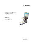
Figure 2-2 illustrates the screen format used by the RSS. Each screen is divided into four sections. The upper
left box (marked 1) always displays “MOTOROLA Radio Service Software” and the radio name. This box also
displays the branch of the program tree (see paragraph 2.5) and the page number for multiple-page displays.
For this example, the MAIN Menu is the top level of the program and no branch information is shown.
MOTOROLA Radio Service Software
GTX
Model:
Select Function F1 - F10.
(1)
MAIN
(2)
MAIN MENU
(3)
F1
F2
F3
F4
F5
F6
F7
F8
F9
F10
F1
HELP
F2
SERVICE
-
HELP
SERVICE Alignment Service Aids, Board Replacement
GET/SAVE/PROGRAM Codeplug Data
CHANGE/CREATE/VIEW Codeplug Data
PRINT Codeplug Data
SETUP Computer Configuration
Exit Radio Service Software, Return to DOS
F3
GET
SAVE
F4
CHANGE
VIEW
F5
PRINT
F6
F7
USER
LEVEL
F8
F9
SETUP
F10
EXIT
Figure 2-2. Sample Screen
The upper right box (marked 2) displays operating instructions. In this example, “Select Function Key F1 - 10.”,
tells the operator that he or she must press one of the Function Keys to select an operation. Error messages
and data entry errors are also displayed in this box.
The large center box (marked 3) will contain menu descriptions or data entry fields. In this example, the “MAIN
MENU” is displayed, with detailed descriptions of the function keys. Menu screens may direct you to other
menu screens or directly to data entry screens.
Data entry screens require you use the UP/DOWN arrow keys to make selections from a predetermined list or
to enter data directly from the keyboard. The instruction message (box 2) always indicates what type of
response is required. The current data entry field is always highlighted, since there are generally several data
entry fields on a single screen. Press the ENTER (or TAB) key to move to the next data entry field. If you make
a typing error, move the cursor under the error with the LEFT/RIGHT arrow keys and type over the error. All
keyboard commands are summarized in the next section. The bottom box (marked 4) labels the function
keys for each screen. For menu screens, such as this example, the capitalized text from box 3 corresponds
directly to the function key labels. The F1 and F10 function keys perform the same functions for all RSS
screens.
The F1 function key is used to access the HELP function. At any time, you may press F1 to get more information about the menu or data field being displayed. The F10 function key is used to EXIT the current screen and
to return to the previous screen. If you attempt to exit a Service screen before you program the new data, you
will be prompted “Are You Sure?” and can choose to Abort the Exit.
GETTING STARTED
5
2.4
HOW TO USE THE KEYBOARD
All RSS keyboard commands are summarized in this section. The F1 HELP function also provides keyboard
information. From any screen, you may view this list by pressing F1 (HELP) and then press F2 (KEYBOARD
HELP).
F1:
F1-F9:
F10:
ESC:
TAB (or ENTER):
Shift TAB:
UP/ DOWN Arrow keys:
LEFT / RIGHT Arrow:
INSERT:
BACKSPACE:
DELETE:
HOME:
PAGE UP / PAGE DN:
6
Help Information
Execute Labeled Function
Return to the PREVIOUS Menu
Return to the MAIN Menu
Advance Cursor to Next Data Field
Backup Cursor to Last Data Field
Increment / Decrement Value or Selection
Move Cursor Within Data Field
Insert Space at Current Cursor position
Erase Data Within Field and Move Cursor Left
Erase Current Character
Move Cursor To Upper Left Data Field
Change Displayed Page
GETTING STARTED
2.5
HOW THE SCREENS ARE ORGANIZED
The RSS screens are organized in a tree, as shown in Figure 2-3. You cannot randomly jump from one screen
to another, but must move up and down the branches by using the menu screens and function keys. Refer to
paragraph 2.8 for an explanation of the MAIN Menu functions.
MAIN MENU
F1
F2
HELP
F3
SERVICE
GET/SAVE
F4
CHANGE/
VIEW
F2 - READ CODEPLUG
F3 - GET FILE
F4 - GET STANDARD FILE
F5 - CLONE CODEPLUG
F1 - MORE HELP
F2 - KEYBOARD HELP
F9 - OTHER HELP
F7
F8
PRINT
F9
SETUP
RADIO WIDE
F6 - SCAN/ROAM OPTs
F10
EXIT TO
DOS
F6 - TG SCAN LISTS
F3 - COMM TEST
F2 - CONFIGURATION
F3 - SUMMARY
F4 - TRUNKING
F5 - MODES
F6 - ARCHIVES
F7 - COLORS
F7 - PHONE NUMBER
F7 - SAVE FILE
F8 - PROG CODEPLUG
F8 - DTMF OPTIONS
F4
ALIGNMENT
MODE CONFIG
F3 - DEVIATION
F5 - REF. OSCILLATOR
F7 - TX POWER
F8 - SQUELCH
F6
F6
F3 - PC CONFIG
F2
F5 - LIMITED CLONE
F8 - PROG CODEPLUG
F2
F5
F8 - SITE ACCESS
F9 - SITE BLOCK
BOARD
REPLACEMENT
F2 - LOGIC/RF BOARD
F4 - PA BOARD
F6
F5 - TX DEVIATION CALIBRATION
TRUNKED
CONFIG
F6 - LISTS
F4 - ATG LIST
F5 - CALL LIST
F8 - SYSTEM INFORMATION
F7- SMART DATA
F9 - PERSONALITY OPTIONS
F9
UTILITIES
F2 - ADD MODE
F3 - DELETE MODE
F4 - MOVE MODE
F6 - ADD TRUNK PERSONALITY
F7 - DELETE TRUNK PERSONALITY
F8 - MOVE TRUNK PERSONALITY
Figure 2-3. Radio Service Software Organization
Note:
This manual covers the Motorola and LTR (E.F.Johnson) Protocols. Therefore, depending on
the model, the user must choose whether to program the codeplug with the Motorola or LTR
Protocol.
GETTING STARTED
7
2.6
HOW TO INSTALL THE SOFTWARE
A. HARD DISK INSTALLATION
To install the software on your hard disk, an installation program is included on PROGRAM DISK #1. The
install program will ask which disk the RSS should be installed on, and will also ask for the directory in which
it should be installed. For GTX, a default location of C:\MRSS\GTX will be offered. If you desire to install the
RSS on a different disk or in a different directory than the default, enter the desired disk and directory when
prompted. Once the install location has been chosen, the following files will be installed at that location:
For GTX:
1. GTX.MDF
2. GTX.EXE
3. GTX.HLP
4. README.TXT
To use the install program, place the PROGRAM DISK #1 into drive A: and log on to drive A:. To start the
install program, type:
INSTALL:
[Press Enter]
NOTE
The install routine uses a decompress algorithm and the install time is dependent upon the
computer’s speed.
After installing, the program displays that the installation has been successfully completed. Remove the supplied copy of the RSS and store it in a safe place. This will ensure that you will always have an uncorrupted
copy available should anything happen to your hard disk.
The install routine automatically creates two sub-directories for storage of archive files: ARCHIVE and
BACKUP. These files are created in the directory where you installed the RSS.
To create the System Key File path name, type:
MKDIR C:\MRSS\GTX\SYS_KEYS
[Press Enter]
To complete the installation procedure for hard disk operation, you must start the program to configure it for
your application (monitor type, serial port). To start the program, type:
GTX.exe
8
[Press Enter]
GETTING STARTED
2.7
HOW TO CONFIGURE THE SOFTWARE FOR YOUR COMPUTER
The first time the RSS is installed, the program may initially respond with a SERVICE SOFTWARE CONFIGURATION Menu as shown in Figure 2-4. The SERVICE SOFTWARE CONFIGURATION Menu has two active
function keys, F3 and F7.
MOTOROLA Radio Service Software
GTX
Model:
Select Function F1 - F10.
(1)
SETUP
(2)
SERVICE SOFTWARE CONFIGURATION MENU
(3)
F1
F2
F3
F4
F5
F6
F7
F8
F9
F10
F1
HELP
F2
-
HELP
PC CONFIGURATION: Drives, Paths, Ports, Etc.
SCREEN COLOR Configuration
Exit/Return to MAIN Menu
F3
PC
CONFIG
F4
F5
F6
F7
SCREEN
COLOR
F8
F9
F10
EXIT
Figure 2-4. Service Software Configuration Menu
Press the F3 function key to access the CONFIGURE COMPUTER screen (Figure 2-5) to set default disk
drive paths for Archive, Backup, System Key files. This is also used to select the communications port (COM 1
or COM 2) for the RIB connection.
Refer your computer owner's manual for a complete description of path names and asynchronous communication ports.
GETTING STARTED
9
MOTOROLA Radio Service Software
GTX
Model:
Select Function Key F1 - F10
SETUP:COMPUTER
CONFIGURE COMPUTER
DEFAULT PATH NAMES
Archive
Backup
STD File
Sys Key
Archive
SERIAL PORTS
RIB .................COM 1
F1
HELP
F2
F3
COMM
TEST
F4
F5
READ
PRINT
SYS KEYS SCREEN
F6
F7
F8
SAVE
F9
F10
RESET EXIT
DEFAULT
Figure 2-5. Configure Computer Screen
Use the following steps to configure your computer:
1.
Enter the default disk drive where you plan to keep your archive files. If you have a hard disk system
and want to save archive files on the hard disk, enter the Archive File path name which was created
previously (see paragraph 2.6). Example:
ARCHIVE
For a floppy disk system, you should enter disk drive A:\ or B:\.
2.
Next, you must enter a default BACKUP disk drive for your archive files if you have chosen to store
your archive files on your hard disk. Enter either A:\ or B:\
After archiving a codeplug file to a hard disk sub-directory, the RSS automatically prompts you to
install a floppy disk in this drive to make a backup. If you have a dual floppy system, skip to step 3.
Diskette backups for dual-floppy systems should be handled via standard DOS file copy procedures.
3.
If you have been assigned System Keys, then it will be necessary to define the path name in which
the System Key files reside. If you have a hard-disk system, enter the System Key file path name
which you created previously.
Example: C:\MRSS\SYS_KEYS
Once the System Key path is defined, the user may load System Key files using the READ SYS
KEYS (F4) function. If the System Key path name is stored (step 6) then during program start-up, the
RSS will automatically load the System ID from every valid System Key found in the specified drive
and path.
10
GETTING STARTED
4.
Use the UP/DOWN arrow keys to select to which Asynchronous Communications Port (COM 1 or
COM 2) your RIB (Radio Interface Box) is connected.
If you are not sure how your computer is configured or if you have two Asynchronous
Communications Ports, the COMM TEST (F3) function may be used to verify that your computer
is able to READ and PROGRAM a radio codeplug properly.
The COMM TEST function will verify your system is functioning properly by sending commands to
the radio and checking for the proper response. No codeplug changes will result from these
commands. An OK response will be displayed in the Status Window if the system checks OK.
After the computer and RIB are connected as given in paragraph 2.2, turn the radio on, and execute
COMM TEST by pressing F3. If the communication test fails, select COM 2 and repeat COMM TEST.
If the test fails the second time, check your setup as given in Paragraph 2.2.
5.
To complete the computer configuration, press F8 to SAVE the configuration information to a file
on the program disk. Every time you use the RSS, the configuration that you SAVED last will be used.
At anytime the configuration may be changed and SAVED.
All selections may be reset to the original values by pressing the F9 (RESET DEFAULT) function key.
Note RESET DEFAULT does NOT save the configuration. If the default values are desired, you must
save them by pressing F8 (SAVE).
6.
Press F10 to return to the PROGRAMMER CONFIGURATION menu. If you have a color monitor,
continue with step 8. Otherwise, this completes the software installation procedure. Press F10 again
to move to the Banner screen and then press any key to continue to the MAIN Menu. The MAIN Menu
is described in Section 2-8.
7.
Press F7 function key to access the CONFIGURE SCREEN screen (Figure 2-6) to enable the color
display option and configure your screen colors.
A color monitor and color display interface card is required for proper color operation. Please refer to
your computer owner's manual and/or ask your computer dealer if you have questions regarding the
color capability of your computer.
GETTING STARTED
11
MOTOROLA Radio Service Software
GTX
Model:
Use UP/DOWN Arrows to Enable.
SETUP:SCREEN
CONFIGURE SCREEN
MONITOR TYPE.................. .Color
TEXT.........................Yellow
STATUS LINE...................White
MESSAGE LINE..................White
HIGHLIGHT.....................White
BACKGROUND.....................Blue
Screen Outline...............Lt Red
F1
HELP
F2
F3
F4
F5
PRINT
F6
F7
F8
SAVE
F9
RESET
F10
EXIT
Figure 2-6. Configure Screen
8.
Use the UP/DOWN arrow keys to select COLOR MONITOR TYPE. Once COLOR is enabled, you
may change the colors of various sections of the display. Press the TAB or ENTER key to change
fields and use the UP/DOWN arrow keys to change colors.
NOTE
For some portable or laptop computers with LCD displays, it may be necessary to configure
the MONITOR TYPE as MONO in order to see the cursor during typical operation. Adjusting
the color combinations while running in COLOR mode will also provide a method to improve
cursor visibility. To save your selections, press the F8 function key. Pressing F9 will return the
screen to the default settings.
This completes the software installation procedure. Press F10 twice to move to the Banner screen. Press any
key to return to the MAIN Menu.
12
GETTING STARTED
2.8
THE MAIN MENU
The MAIN Menu (Figure 2-7) is the top level of the program tree as shown in Figure 2-3. The RSS provides
four basic functions which are selected from the MAIN Menu:
1.
2
3.
4.
SERVICE
GETTING (or SAVING) Codeplug Data
CHANGING (or VIEWING) Codeplug Data
PRINTING Codeplug Data
MOTOROLA Radio Service Software
GTX
Model:
Select Function F1 - F10.
(1)
MAIN
(2)
MAIN MENU
(3)
F1
F2
F3
F4
F5
F6
F7
F8
F9
F10
F1
HELP
F2
SERVICE
-
HELP
SERVICE Alignment Service Aids, Board Replacement
GET/SAVE/PROGRAM Codeplug Data
CHANGE/CREATE/VIEW Codeplug Data
PRINT Codeplug Data
SETUP Computer Configuration
Exit Radio Service Software, Return to DOS
F3
GET
SAVE
F4
CHANGE
VIEW
F5
PRINT
F6
F7
USER
LEVEL
F8
F9
SETUP
F10
EXIT
Figure 2-7. The MAIN Menu
After making a selection via the function keys, you will be directed to similar menus and/or data entry screens.
From any point in the program, you may always return to the MAIN Menu by pressing the ESC (Escape) key.
Each programmer function is described in detail in the remainder of this section. F1 - The HELP function gives
specific information regarding the current menu or highlighted data field. From the Help function, general information is available by pressing F1 again (MORE HELP).
In addition, the HELP function provides access to:
KEYBOARD HELP
PRINT HELP
OTHER HELP
(F3) - A summary of the keyboard commands
(F5) - Hard copy of the Help information
(F9) - Radio serial number, software version numbers, cable numbers, etc.
F2 - The SERVICE function is a multi-level menu that permits access to radio ALIGNMENT, UPDATE, and
BOARD REPLACEMENT screens. The radio contains no internal alignment or tuning adjustments; all
alignment is performed via the SERVICE screens.
A radio must be connected to your computer via the RIB before you will be permitted to access the
SERVICE screens. All SERVICE screens access the codeplug directly; therefore, you do NOT have
to read the codeplug data (via the GET/SAVE functions) before using the SERVICE screens.
All SERVICE functions are explained in Section 3.
GETTING STARTED
13
F3 - The GET/SAVE function is used to READ codeplug data from a radio and/or GET an archived
codeplug image from a diskette or hard disk for editing purposes (via the CHANGE/VIEW function).
GET/SAVE is also used to PROGRAM modified codeplug data back into the radio, or SAVE an
archive file on a diskette (or hard disk). Radio/Codeplug CLONING is also available via the GET/
SAVE function.
All GET/SAVE functions are explained in Section 4.
F4 - The CHANGE/VIEW function is a multi-level menu that is used to change, view, or modify codeplug
features and option configurations. The radio codeplug parameters are classified as RADIO-WIDE,
MODE, and TRUNKED related. CHANGE/VIEW permits access to each of these categories.
Unlike the SERVICE function, a codeplug must be loaded into your computer's memory (via the
GET/SAVE functions) before you can access the CHANGE/VIEW screens. You may CHANGE/VIEW
an archive file without a radio connected.
All CHANGE/VIEW functions are explained in Section 5.
F5 - The PRINT function produces permanent records of codeplug configurations and/or RF alignment
settings. A printer is required and should be connected to your computer per your instruction manual.
All PRINT functions are explained in Section 6.
F9 - The SETUP function, previously discussed in Section 2-7, is used to configure your Radio Service
Software to your particular application. Default disk drives, communication ports, and even screen
colors may be customized to your specific needs.
F10- The EXIT function is used to quit the program and return to DOS. Be sure all desired codeplug
changes have been programmed back to the radio, and that an archive copy has been made.
Otherwise all changes will be lost since returning to DOS erases this data from the computer's
memory.
14
GETTING STARTED
3.0
SERVICING THE RADIO
All radio alignment and board replacement procedures are accessed from the service menu. A radio must be
connected to your computer via a Rib Interface Box (RIB) and cables and the radio turned on before you are
permitted to access the service screens. Figure 3-2 illustrates how the service screens are organized.
MOTOROLA Radio Service Software
GTX
Model:
Select Function F1 - F10.
Read Radio Completed Successfully.
SRVC
SERVICE MENU
-----------F1
F2
F3
F4
F5
F6
F7
F8
F9
F10
-
F1
F2
HELP ALIGNMENT
HELP
ALIGNMENT: Transmitter And Receiver
BOARD REPLACEMENT Procedure
EXIT, Return to MAIN Menu
F3
F4
F5
F6
BOARD
REPLACEMENT
F7
F8
BLANK
BOARD
F9
F10
EXIT
Figure 3-1. Service Menu
Function Key Descriptions:
F2 - Select ALIGNMENT to perform standard radio alignment procedures:
Transmitter VCO Deviation Adjustment Transmitter Power Set
Reference Oscillator Warp Adjustment Squelch Adjustment
F6- The BOARD REPLACEMENT function is used for servicing the radio when board repairs and/or
replacement are required. Special initialization procedures and step-by-step instructions are given
for all realignment procedures when replacing or servicing one or more of the following area:
Logic Board or RF Board
TX Deviation Calibration
Power Amplifier (PA) Board
All service screens read and program the radio codeplug directly; you do not have to use the GET/SAVE functions to use the service menus. You will be prompted at each service screen to save the new values before
exiting the screen.
IMPORTANT
Do not switch off your radio in the middle of any service procedure. Always use the EXIT key
to return to the MAIN menu screen before disconnecting the radio. Improper exits from the
service screens may leave the radio in an improperly configured state and result in seriously
degraded radio or system performance.
SERVICING THE RADIO
15
The service screens introduce the concept of a "softpot", an analog “Potentiometer” controlled by “Software”.
As stated earlier, the radio does not contain any internally adjustable components. All RF and tuning adjustments are controlled by software.
Each service screen provides the capability to increase or decrease the 'softpot' setting with the keyboard UP/
DOWN arrow keys respectively. A graphical scale is displayed indicating the minimum, maximum, and current
value of the softpot setting.
When softpot value is adjusted, information is sent to the radio to increase (or decrease) a DC voltage in the
corresponding circuit. For example, when on the Reference Oscillator Warp Adjustment screen, you press the
UP arrow key to increase the frequency, which in turn provides instructions to the radio microprocessor to
increase the voltage across a varactor in the reference oscillator.
In ALL cases, the softpot value is just a relative number, corresponding to a D/A (digital-to-analog) generated
voltage in the radio. All standard measurement procedures and test equipment are applicable and are NOT
affected in any way.
MAIN MENU
SERVICE
F1
F2
HELP
F3
F4
ALIGNMENT
F5
F6
F7
F8
F9
F10
RETURN TO
MAIN MENU
BOARD
REPLACEMENT
F2 LOGIC/RF BOARD
F3 DEVIATION
F3
F5 REF OSCILLATOR
F4 - PA BOARD
F7 TX POWER
F5 - TX DEVIATION CALIBRATION
F8 SQUELCH
F6
F8
Figure 3-2. Service Screens Organization
16
SERVICING THE RADIO
3.1
ALIGNMENT
Standard periodic alignment procedures are performed from the ALIGNMENT Menu. These include:
1.
2.
3.
4.
Transmitter VCO Deviation Adjustment
Reference Oscillator Warp Adjustment
Transmitter Power Set
Squelch Adjustment
MOTOROLA Radio Service Software
GTX
Model:H11UCD6B1_N
Select Function F1 - F10.
SRVC: ALGN
ALIGNMENT MENU
F1
F2
F3
F4
F5
F6
F7
F8
F9
F10
F1
HELP
F2
-
HELP
DEVIATION Adjustment
REFERENCE OSCILLATOR WARP Adjustment
TRANSMITTER POWER Adjustment
SQUELCH Adjustment
EXIT/Return to Service Menu
F3
DEVIATION
SET
F4
F5
REF OSC
WARP
F6
F7
TX
PWR SET
F8
SQUELCH
ADJUST
F9
F10
EXIT
Figure 3-3. Alignment Menu
SERVICING THE RADIO
17
3.1.1 TRANSMITTER DEVIATION
Refer to your service manual for the DEVIATION ALIGNMENT procedure. Deviation must be checked when
the radio is serviced, and must be readjusted after any Compensation adjustments are made. Motorola Radio
Service Software (RSS) uses UP/DOWN arrows to adjust value.
MOTOROLA Radio Service Software
GTX
Model: H11UCD6B1_N
Use UP/DOWN Arrows to Adjust Value.
SRVC:ALGN:TX DEV
BALANCE ATTENUATOR ADJUSTMENT
63
0
Relative Value = 26
MIN
MAX
DEVIATION ATTENUATOR ADJUSTMENT
0
255
MIN
MAX
Relative Value = 42
TRANSMITTER OFF
F1
HELP
F2
F3
TOGGLE
LINE
F4
F5
60/2.5 PRINT
KHZ
SCREEN
F6
TOGGLE
PTT
F7
F8
PROGRAM
VALUE
F9
F10
EXIT
Figure 3-4. Transmitter Deviation Adjustment
The Radio has two adjustments for Transmit Deviation. Use Balance ATTENUATOR ADJUST meter to balance the deviation between high and low frequency. Use deviation ATTENUATOR meter to adjust the deviation level. Use the F3 “Toggle Line” function key to switch between the two adjustments.
18
SERVICING THE RADIO
3.1.2
REFERENCE OSCILLATOR WARP
Refer to your service manual for the REFERENCE OSCILLATOR ALIGNMENT procedure.
NOTE
The radio internal circuitry must be at room temperature (25 +/- 3 degree C; 77 +/- 5 degree
F) to properly center the adjustment. Additionally, the radio should not be heated by transmitting or operating at a loud audio setting for a long period of time. Turn the radio off and let the
radio cool thoroughly to room temperature before setting the Reference Oscillator.
MOTOROLA Radio Service Software
GTX
Model: H11UCD6B1_N
Use UP/DOWN Arrows to Adjust Value.
SRVC:ALGN:REF OSC WARP
REFERENCE OSCILLATOR WARP ADJUSTMENT
0
127
MIN
MAX
Relative Value = 59
TRANSMITTER ON 804.1625 MHz
(Note: Test Frequency)
F1
HELP
F2
F3
F4
F5
PRINT
SCREEN
F6
TOGGLE
PTT
F7
F8
PROGRAM
VALUE
F9
F10
EXIT
Figure 3-5. Reference Oscillator Warp Adjustment
Before warping, connect the radio antenna output to some frequency measuring equipment like the R 2000.
The reference oscillator is warped by first keying the radio via F6, and then by pressing the UP/DOWN arrow
keys respectively. A relative warp value is displayed, but the actual transmitter frequency must be determined
from your frequency counter or service monitor. A three minute time-out-timer is enabled when the radio is
keyed via the F6 key.
Using the UP/DOWN arrow keys, adjust the Reference Oscillator Warp to the frequency displayed on the
screen. Press F6 again to de-key the radio, and then press F8 to program the value to the radio.
SERVICING THE RADIO
19
3.1.3 TRANSMITTER POWER
Refer to your service manual for the TRANSMITTER POWER ALIGNMENT procedure.
MOTOROLA Radio Service Software
GTX
Model: H11UCD6B1_N
Use UP/DOWN Arrows to Adjust Value.
SRVC:ALGN:TX PWR
TRANSMITTER POWER ADJUSTMENT
127
0
MIN
MAX
Relative Value = 59
TRANSMITTER ON 804.8625 MHz
F1
HELP
F2
F3
TOGGLE
LINE
F4
F5
60/2.5 PRINT
KHZ
SCREEN
F6
TOGGLE
PTT
F7
F8
PROGRAM
VALUE
F9
F10
EXIT
Figure 3-6. Transmitter Power Adjustment
Transmitter Power is adjusted by first keying the radio via F6, and then by pressing the UP/DOWN arrow keys
to increase or decrease power respectively. A relative Tx Power value (NOT WATTS!) is displayed, but the
actual transmitter power output must be determined from your service monitor.
The radio will transmit on the frequency displayed on the screen and should be terminated into a 50 ohm load
or service monitor. A three minute time-out-timer is enabled when the radio is keyed via the F6 key.
Using the UP/DOWN arrow keys, adjust the Transmitter Power per your service manual. Press F6 again to dekey the radio, and then press F8 to program the value to the radio.
20
SERVICING THE RADIO
3.1.4
SQUELCH
Refer to your service manual for the SQUELCH procedure.
MOTOROLA Radio Service Software
GTX
Model: H11UCD6B1_N
Use UP/DOWN Arrows to Adjust Value.
SRVC:ALGN:SQUELCH TONE
SQUELCH ATTENUATOR
63
0
MIN
MAX
Relative Value = 50
FREQUENCY 870.1625 MHz
F1
HELP
F2
VOLUME
-
F3
VOLUME
+
F4
F5
PRINT
SCREEN
F6
F7
F8
PROGRAM
VALUE
F9
F10
EXIT
Figure 3-7. Portable Squelch Attenuator
The squelch attenuator setting is increased or decreased by pressing the UP/DOWN arrow keys respectively.
A relative value between 0 and 63 is displayed on the screen. Adjust the squelch setting to the desired value.
This screen allows you to adjust the squelch level for Test Mode Frequency. Use the UP/DOWN arrows to
change the value of the squelch.
The volume level keys enable you to adjust the volume level of the squelch when it is opened.
SERVICING THE RADIO
21
3.2
BOARD REPLACEMENT/REPAIR
The BOARD REPLACEMENT function is used for servicing the radio when board repairs and/or replacement
are required. Special initialization procedures and step-by-step instructions are given for all realignment procedures when replacing or servicing one or more of the following areas:
Logic Board
Power Amplifier (PA)
TX Deviation Calibration
Refer to your service manual for BOARD REPLACEMENT procedures.
MOTOROLA Radio Service Software
GTX
Model:
Select Function F1 - F10.
SRVC:BD REPLC
BOARD REPLACEMENT MENU
F1
F2
F3
F4
F5
F6
F7
F8
F9
F10
-
F1
F2
HELP LOGIC OR
RF BD
HELP
LOGIC ON RF BOARD
POWER AMPLIFIER BOARD
TX Deviation Calibration
EXIT/Return to SERVICE Menu
F3
F4
PA BD
F5
DEV
F6
F7
F8
F9
F10
EXIT
Figure 3-8. Board Replacement Menu
Each procedure is structured for execution in a top-to-bottom order to ensure proper calibration.
22
SERVICING THE RADIO
3.2.1
LOGIC OR RF BOARD REPLACEMENT
Replacing the Command Board requires the microprocessor to be initialized and the radio to be completely
re-aligned. This procedure is used to perform both tasks. Verify that you have the proper alignment equipment
ready before attempting this procedure. Once the alignment sequence is started, all steps must be completed
in the listed sequence.
MOTOROLA Radio Service Software
GTX
Model:
Select Function F1 - F10.
SRVC:BD REPLC:LOGIC BD
LOGIC or RF BOARD REPLACEMENT PROCEDURES
Step
1
2
3
4
5
6
7
8
9
10
F1
HELP
-
Refer
Press
Press
Press
Press
Press
to
F2
F3
F4
F5
F6
Your Service Manual for Additional Information
to Enter ALIGNMENT REFERENCE DATA
to Set TX POWER
to WARP REFERENCE OSCILLATOR
to Set TX POWER CALIBRATION
to Set TX DEVIATION CALIBRATION
Press F9 to Set Squelch Adjustment
Press F10 to EXIT and Enter GET/SAVE to Archive Data
F2
F3
DEFAULT
TX
DATA
PWR SET
F4
WARP
FREQ
F5
F6
TX
TX
PWR CAL DEV CAl
F7
F8
F9
SQUELCH
ADJUST
F10
EXIT
Figure 3-9. Logic Board Replacement
Refer to your service manual for LOGIC or RF BOARD replacement procedures. Only the function key for the
step highlighted is active.
The replacement LOGIC OR RF Board should be installed per the service manual instructions. All replacement Command Boards are pre-programmed to enable the radio to function only at a test-mode level.
Perform steps from 2 through 9 to complete the required radio alignment. The RSS program does not allow
the skipping of steps.
SERVICING THE RADIO
23
3.2.2 TRANSMITTER POWER CALIBRATION PROCEDURE
Refer to your service manual for the TRANSMITTER POWER CALIBRATION procedure. Use the ENTER key
to move to the next step. Only the function key for the step indicated is active.
MOTOROLA Radio Service Software
GTX
Model:
Use UP/DOWN Arrows to Adjust Value.
SRVC:BD REREPLC:TX PWR CAL
TRANSMITTER POWER CALIBRATION PROCEDURE
255
0
Point
1
2
3
4
Value
158
158
159
160
Point
5
6
7
8
Value
161
162
162
163
Point
9
10
11
12
Value
137
138
139
140
Point
13
14
15
16
Value
141
141
142
143
F8
PROGRAM
VALUE
F9
TRANSMITTER OFF
F1
HELP
F2
F3
F4
F5
PRINT
SCREEN
F6
TOGGLE
PTT
F7
F10
EXIT
Figure 3-10. Transmitter Power Calibration
24
SERVICING THE RADIO
3.2.3 TX Deviation Calibration
MOTOROLA Radio Service Software
GTX
Model:
Use UP/DOWN Arrows to Adjust Value.
SRVC:BD REREPLC:TX DEV CAL
TRANSMITTER BALANCE CALIBRATION PROCEDURE
63
0
Point
1
2
3
4
Value
26
23
24
25
Point
5
6
7
8
Value
26
27
28
29
Point
9
10
11
12
Value
30
31
32
33
Point
13
14
15
16
Value
34
35
36
37
F8
PROGRAM
VALUE
F9
TRANSMITTER OFF
F1
HELP
F2
F3
F4
F5
PRINT
SCREEN
F6
TOGGLE
PTT
F7
F10
EXIT
Figure 3-11. TX Deviation Calibration (1 of 2)
The TX Deviation contains two adjustment screens: Balance Attenuator and Deviation Attenuator.
Balance Attenuation
Balance Attenuator Alignment is required after replacing or servicing the board. This alignment procedure balances the modulation contributions of the low and high frequency portions of a baseband signal. Proper alignment is critical to the operation of signalling schemes that have very low frequency components (i.e) DPL
which could result in distorted waveforms if not adjusted properly.
This procedure needs to be performed at multiple frequencies to allow proper alignment across the entire RF
band. The RF band is divided into frequency zones with calibration point (value) in each zone.
The following procedure should be carried out by qualified service personnel:
1.
2.
3.
4.
5.
6.
7.
8.
9.
Press F6 to key-up radio. The radio’s RF input must be terminated into a 50 Ohms load.
Set the Tx deviation as a reference.
Press F4 to switch to 2.5 KHz.
Modify the balance attenuator setting using the UP/DOWN arrow keys.
Measure the actual Tx deviation with a service monitor.
Repeat steps 4 and 5 until balance deviation specification is achieved.
Press F6 to de-key the radio.
Use the tab key to move between frequency points.
Press F8 to save the new values.
SERVICING THE RADIO
25
MOTOROLA Radio Service Software
GTX
Model:
Use UP/DOWN Arrows to Adjust Value.
SRVC:BD REREPLC:TX DEV CAL
TRANSMITTER DEVIATION CALIBRATION PROCEDURE
255
0
Point
1
2
3
4
Value
60
61
0
63
Point
5
6
7
8
Value
64
65
66
67
Point
9
10
11
12
Value
68
69
70
71
Point
13
14
15
16
Value
72
73
74
75
F8
PROGRAM
VALUE
F9
TRANSMITTER OFF
F1
HELP
F2
F3
F4
F5
PRINT
SCREEN
F6
TOGGLE
PTT
F7
F10
EXIT
Figure 3-12. TX Deviation Calibration (2 of 2)
Deviation Attenuation
Deviation Attenuator Alignment is required after replacing or servicing a board. This procedure needs to be
performed at multiple frequencies to allow proper alignment across the entire RF band. The RF band is
divided into frequency zones with calibration point (value) in each zone.
The following procedure should be carried out by qualified service personnel:
1.
2.
3.
4.
5.
6.
7.
8.
26
Press F6 to key-up radio. The radio’s RF input must be terminated into a 50 Ohms load.
Apply the appropriate signal as instructed in the service manual.
While transmitting, modify the deviation attenuator setting using the UP/DOWN arrow keys.
Measure the actual TX deviation with a service monitor.
Repeat steps 4 and 5 until TX deviation is achieved.
Press F6 to de-key the radio.
Use the tab key to move between frequency points.
Press F8 to save the new values.
SERVICING THE RADIO
4.0
GET/SAVE CODEPLUG DATA
The GET/SAVE functions are used to transfer codeplug data from your radio or an archive file into your computer, thus enabling you to change, view, or print. The GET/SAVE function also permits you to program modified data back into your radio or to save a copy of the codeplug data in an archive file. The GET/SAVE menu is
shown in Figure 4-1.
IMPORTANT
Do not turn off the radio or disconnect it from the computer while attempting to program the
codeplug. Interrupting the programming process will destroy the codeplug contents and
completely disable the radio. If an accident does occur, the radio may be restored from the
archive file. For this reason, the archive file should always be created before programming
the radio.
MOTOROLA Radio Service Software
GTX
Model:
Select Function F1 - F10.
GET/SAVE
GET/SAVE MENU
F1
F2
F3
F4
F5
F6
F7
F8
F9
F10
F1
HELP
-
F2
READ
CODEPLUG
HELP
READ Data from Codeplug
GET Codeplug Data from Archive Disk File
GET Codeplug Updated from Standard File
CLONE (COPY) Codeplug
SAVE Codeplug Data to Archive File Disk
PROGRAM Data into Radio Codeplug
EXIT and Return to MAIN MENU
F3
GET
FILE
F4
F5
F6
F7
F8
GET
CLONE UPGRADE SAVE
PROGRAM
STD FILE CODEPLUG RADIO CODEPLUG DATA
F9
F10
EXIT
Figure 4-1. GET/SAVE Menu
Function Key Descriptions:
F2 -The READ CODEPLUG function reads the information (data) stored in the radio codeplug
(EEPROM) and transfers it to the computer's memory. Ensure that the radio and RIB are properly
connected to the computer, and power turned on before using the READ function.
The time required to READ a codeplug will depend directly on your computer type and the size of
the codeplug you are reading. The status of the READ operation is displayed at the bottom of the
screen.
F3 -The GET Archive File function is used to retrieve an archive file from a diskette or from a hard disk.
Once retrieved, the file may be modified via the CHANGE/VIEW functions or programmed into a
radio just as codeplug information read from the radio via the F2 READ function.
F4 -The GET Standard File function is used to update information from the disk file.
F5 -The CLONE Codeplug function is used to quickly reprogram a large number of radios by allowing
the user to change Individual IDs and the serial number from within one screen while maintaining
all other programmed values.
GET/SAVE CODEPLUG DATA
27
F6 - The UPGRADE RADIO functions are used to transfer codeplug data from radio or an archive file
into the computer for upgrading, changing, viewing, or printing it. The data may also be programmed
back into the radio or saved in a file.
F7 - The SAVE FILE function is used to create (or update) an archive copy of the codeplug information
onto a diskette or hard disk. An archive copy of every radio installed or serviced is strongly
recommended to be able to quickly restore customer information in case of a codeplug failure.
F8 - The PROGRAM CODEPLUG function is used to transfer codeplug information from the computer to
the radio codeplug. After pressing the F8 function key, you will be prompted to press it a second time
to prevent accidental programming. Ensure that the radio and RIB are properly connected to the
computer, and power turned on before using the PROGRAM function.
4.1
READ CODEPLUG
The READ CODEPLUG function first reads the information (data) stored in the radio codeplug (EEPROM)
and then transfers it to the computer's memory.
A radio and RIB must be properly connected to the computer and power turned ON before you attempt the
READ function.
The time required to read a codeplug depends directly on the size of the codeplug being read. The status of
the READ operation is displayed at the bottom of the screen.
MOTOROLA Radio Service Software
GTX
Model:
Please Wait.
Accessing Serial Bus.
GET/SAVE:READ CODEPLUG
READ RADIO CODEPLUG
Reading Codeplug Block 07 of 35
0%
F1
F2
25%
F3
F4
50%
F5
75%
F6
F7
100%
F8
F9
F10
Figure 4-2. Read Codeplug
28
GET/SAVE CODEPLUG DATA
4.2
GET FILE
The GET FILE function is used to retrieve an archive file from a diskette or hard disk. Once retrieved, the file
may be modified via the CHANGE/VIEW functions or programmed into a radio just as codeplug information is
read from the radio via the F2 READ function.
Use the TAB (or ENTER) key to select the serial number of the radio to be retrieved. The corresponding model
number, customer identification information, and the date the file was created will be displayed across the
middle of the screen. The F8 function key is used to get the selected file as described below.
MOTOROLA Radio Service Software
GTX
Model:
Select Function Key F1 - F10.
GET/SAVE:GET FILE
Archive Path: A:\MRSS\ARCHIVE
RADIO SERIAL NUMBERS
Model #: H11UGD6CB1_N Customer: NY CITY SERVICE Date: 02-15-98
438HMN0001
438HMN0002
438HMN0003
438HMN0004
438HMN0005
438HMN0006
438HMN0007
438HMN0008
F1
HELP
438HMN0009
438HMN0010
438HMN0011
438HMN0012
438HMN0013
438HMN0014
438HMN0015
438HMN0016
438HMN0017
438HMN0018
438HMN0019
438HMN0020
438HMN0021
438HMN0022
438HMN0023
438HMN0024
F2
F3
F4
F5
CHANGE
ADD
DELETE
PRINT
ARCHIVE ARCHIVE ARCHIVE ARCHIVE
438HMN0025
438HMN0026
438HMN0027
438HMN0028
438HMN0029
438HMN0030
438HMN0031
438HMN0032
F6
ENTER
S/N
438HMN0033
438HMN0034
438HMN0035
438HMN0036
F7
F8
GET
GET
CURRENT SELECTED
F9
F10
EXIT
Figure 4-3. Get Archive File
Function Key Descriptions:
F2 - The CHANGE ARCHIVE function is used to specify the directory path where the archive file is to be
located. The default archive path will always be the specified default path from the SETUP Menu.
F3 - The ADD ARCHIVE function will allow adding an archive file to the archive directory file in the archive
directory path. If the directory file, DBF, is corrupted or erased and can not be recovered from a
backup, then the only way to read the archive files is to add the archive files to another DBF file using
the ADD ARCHIVE function. Refer to Section 7 of this manual for more information on the archive
file structure and the DBF file.
To add a new file, ensure that the archive file is in the Archive path specified (while in DOS). Press F3
(ADD ARCHIVE), enter the 10 character radio serial number and press ENTER. Then enter 1-15
characters for Customer Name or ID and press ENTER. The new file will now be added to the archive
directory file and will be visible on the screen. If the Radio Serial Number entered is less than 10
characters or already exists in the archive directory file, then the add operation will be aborted.
F4 -The DELETE ARCHIVE function erases a file from the archive directory file, DBF. The actual file itself
is not deleted with this command. If an archive file is no longer needed and you want to delete it
to save disk space, use this function to delete it from the directory, then use DOS commands outside
the program to delete the actual archive file. Refer to Section 7 of this manual for more information
on the archive file structure and the DBF file.
GET/SAVE CODEPLUG DATA
29
F6 - The ENTER S/N (serial number) function permits you to enter directly the serial number of the file you
wish to retrieve. After entering the serial number, press ENTER and the computer will search the
specified directory path to locate the file bearing that serial number.
F7 - The GET CURRENT function is used to GET the archive file for the radio currently connected to the
computer. The computer will first READ the radio serial number, and then search the specified
directory path for an archive file for that serial number. Only the specified path will be searched.
Once the file is located, the computer will position the cursor to the archive file bearing that serial
number. Press F8 to GET the file and return to the GET/SAVE menu.
The radio and RIB must be properly connected to the computer and turned ON thus enabling the
GET CURRENT function to operate. Otherwise you will encounter serial buserrors and be instructed
to check your setup.
F8 - The GET SELECTED function is used to GET the archive file highlighted on the screen. After the file
is retrieved, the computer will return to the GET/SAVE menu.
Field Descriptions:
ARCHIVE PATH
Enter the directory path where the archive file is to be located. The default archive path will always be the
specified default path from the SETUP Menu (see page 10). Refer to your computer owner's manual for a
complete description of directories and path names.
SERIAL NUMBER
Enter the serial number of the codeplug archive file that you wish to retrieve and press ENTER. The computer
will search the specified directory path to locate the file if it exists. Only the specified path will be searched.
Once the file is located, press F8 to get the selected file. A status message will inform you if the file does not
exist on the specified path.
Use the page up and down keys to scroll to the list of the archive files if they appear on the next screen(s).
30
GET/SAVE CODEPLUG DATA
4.3
GET STANDARD FILE
The GET STANDARD FILE function is used to upgrade the codeplug information in the computer from standard file. In case of a STANDARD FILE not being available, then an error message is displayed. A STANDARD FILE is not applicable to LTR Radios.
After selecting F4 for Standard file update, the screen shown below will appear.
MOTOROLA Radio Service Software
GTX
Model:
Please Wait.
Accessing Serial Bus.
GET/SAVE:READ CODEPLUG
GET CODEPLUG DATA FROM ARCHIVE FILE
Reading Codeplug Block 01 of 01
0%
F1
F2
25%
F3
50%
F4
F5
75%
F6
F7
100%
F8
F9
F10
Figure 4-4. Get Standard File
GET/SAVE CODEPLUG DATA
31
After the “Standard File” is read, the screen shown below will appear.
MOTOROLA Radio Service Software
GTX
Model:
Select Function Key F1 - F10
GET/SAVE:STANDARD FILE
CURRENT RADIO INFORMATION
Sys Id/ Sz-Flt Ind Id
Per Type Tx Freq PL/DPL
--- ---- ------- ------ ------
NEW RADIO INFORMATION TEMPLATE
Sys Id/ Sz-Flt Ind
Source Per Type Tx Freq PL/DPL
------- ------ -------- --- ----
1.
2.
3.
4.
<STANDARD
<STANDARD
<STANDARD
<STANDARD
<STANDARD
F1
HELP
I
I
i
CONV
F2
UPDATE
RADIO
001E
001E
001E
819.200
F3
D-500
D-500
D-400
4Z
F4
027
027
048
F5
PRINT
SCREEN
F6
FILE
FILE
FILE
FILE
FILE
F7
1
2
3
4
5
ID12
ID12
ID12
ID12
2012
1
I
I
I
I
F8
D-400
D-400
D-400
D-600
D-100
F9
01B
01B
01B
01B
01B
F10
EXIT
Figure 4-5. Standard File Merge
Function Key Descriptions:
F2 - The UPDATE DATA function is used to update the codeplug information in the computer's memory
from the update file download from the ID Assignment System. Upon entering the GET Standard
File screen, the program will attempt to locate the update file for the current serial number. If the file
exists in the Standard File path defined on the setup screen, press the F2 function key to update the
codeplug information.
STANDARD FILE PATH - EDITED ON THE SET UP CONFIGURATION SCREEN
Enter the directory path from where the Standard Update file is to be retrieved. The default path will
always be the specified default path from the SETUP Menu (see page 10).
32
GET/SAVE CODEPLUG DATA
4.4
CLONE RADIO
The CLONE RADIO function is used to copy codeplug information from one radio to another radio. Only
radios with the same model number may be cloned. A radio or radio archive must first be read into the program. One of the two cloning choices can then be made.
MOTOROLA Radio Service Software
GTX
Model:
Select Function F1 - F10.
GET/SAVE; CLONE MENU
CLONE RADIO
F1
F2
F3
F4
F5
F6
F7
F8
F9
F10
F1
HELP
F2
-
HELP
Limited Clone
Clone (Copy) Codeplug Data To Another Radio
EXIT/Return to Get/Save Menu
F3
F4
F5
LIMITED
CLONE
F6
F7
F8
CLONE
RADIO
F9
F10
EXIT
Figure 4-6. Clone Radio Menu
Function Key Descriptions:
F5 - The LIMITED CLONE function will copy codeplug data that has been loaded into the program from
a radio or archive into the radio connected to the computer. Only radios with the same model number
may be cloned. Trunking data base controlled parameters will not be cloned. Only phone list, call lists,
and scan lists will be cloned on trunking radios.
F8 - The CLONE function is used to transfer codeplug information from the computer to the radio
codeplug. Radio’s serial number will be preserved. When F8 is pressed a screen is displayed which
lets the user change the individual IDs and emergency fleet default Individual ID. This function will
not be allowed if a system key is not loaded into the program for all the trunking systems being
programmed into the radio.
GET/SAVE CODEPLUG DATA
33
4.4.1
LIMITED CLONE (Not for LTR Radios)
The LIMITED CLONE function is used to copy codeplug information from one radio to another one. Only
radios with the same model number may be cloned. Trunking data base controlled parameters will not be
cloned. Only phone list, call lists, and scan lists will be cloned on trunking radios. System keys are not
required to perform this operation.
MOTOROLA Radio Service Software
GTX
Press F8 To Program TARGET Radio
or F10 To Return To Menu.
Model:
GET/SAVE; CLONE:LIMITED CLONE
LIMITED CLONE
Note: Conventional personality information, trunking lists
(Call, Phone, Scan), Names (Sts/msg, Site, Mode) will be cloned.
A radio must be connected before continuing clone.
F1
HELP
F2
F3
F4
F5
F6
F7
F8
PROGRAM
CODEPLUG
F9
F10
EXIT
Figure 4-7. Limited Clone
The clone procedure is listed below:
34
1.
Use the GET/SAVE functions to Read the radio codeplug to be cloned, i.e. the "Source" codeplug. An
archive file may also be used as the "Source" codeplug.
2.
Connect the "Target" radio to the computer, and press the F8 function key to program the "Source"
codeplug into the "Target" radio.
GET/SAVE CODEPLUG DATA
4.4.2
CLONE CODEPLUG
The CLONE CODEPLUG function is used to provide rapid reprogramming of radios which are intended to be
common with exception to radio serial number and trunking system individual IDs. Codeplug cloning is
allowed only if the user is a self maintained user with system key files to match the system IDs of each trunking personality, or if the user has an FTR key.
If cloning is allowed, enter the serial number of the radio to be programmed and the Individual ID assigned to
the radio.
MOTOROLA Radio Service Software
GTX
Model:
Enter Radio Serial Number directly.
GET/SAVE; CLONE
TRUNKING TYPE I
EMERGENCY DEFAULT
TRUNKED PERSONALITIES
System Key
----------
Type
----
1...Enabled
2...Enabled
3...Disabled
4...Disabled
5...Enabled
6...Enabled
7...Enabled
8...Enabled
I
I
IIi
IIi
II
I
I
II
F1
HELP
F2
System
------
Sz-Flt/ATG
----------
Indv ID
-------
0137
0137
0199
0199
0321
0734
0734
0500
A-100
B-300
A-100
B-300
800001
C-400
B-201
800002
002
010
700001
700008
700001
020
001
700002
F3
F4
F5
F6
F7
SCROLL SCROLL
PRINT COPY PERS SAVE
UP
DOWN
SCREEN TO EMER FILE
Sz-FLT
------
C-400
B-201
F8
PROGRAM
RADIO
Individ
------
020
001
F9
F10
EXIT
Figure 4-8. Clone Codeplug
Function Key Descriptions:
F3 - The SCROLL UP function is used to page up to the previous group of eight (8) trunking personalities.
F4 - The SCROLL DOWN function is used to page down to the next group of trunking personalities.
F6 - The COPY PERS TO EMER function is used to set all the Type I personality Emergency Default
Individual IDs to the same value as the personality Individual IDs
F7 - The SAVE FILE function is used to create (or update) an archive copy of the codeplug information
onto a diskette or hard disk. If you are creating the file on a hard disk, you will automatically be
instructed to backup the data onto a diskette. Please refer to Section 4.5 for a more detailed
description of the SAVE FILE function.
F8 - The PROGRAM RADIO function programs the attached radio with the trunking personality
information as displayed on the clone screen. The following four conditions e cloning is allowed:
(1) All System Keys must be enabled,
(2) Radios to be cloned to/from must bear the same Model Number,
(3) Radios to be cloned to/from must be from same Product Line, and
(4) Radios to be cloned to/from must have same version of Radio Software.
GET/SAVE CODEPLUG DATA
35
The clone procedure is listed below:
36
1.
Use the GET/SAVE functions to Read the radio codeplug to be cloned, i.e. the “Source” codeplug. An
archive file may also be used as the “Source” codeplug.
2.
Enter the Personality Individual IDs and Emergency Default Individual IDs for the
“Target” radio.
3.
Connect the "Target" radio to the computer, and press the F8 function key to program the “Source”
codeplug into the "Target" radio.
GET/SAVE CODEPLUG DATA
4.5
SAVE FILE
The SAVE FILE function is used to create (or update) an archive copy of the codeplug information onto a diskette or hard disk. If you are creating the file on a hard disk, you will automatically be instructed to backup the
data onto a diskette. This backup procedure is described in the next section.
An optional 15-character name can be given to an archive file to facilitate tracking.
Make an archive copy of every radio you install or service. Thus, in case of codeplug failure you have the
archive copy ready to quickly restore customer information.
MOTOROLA Radio Service Software
GTX
Model:
Enter OPTIONAL Customer Name or ID.
Press F8 to Save File
GET/SAVE:SAVE FILE
Archive Path: A:\MRSS\ARCHIVE
SAVE CODEPLUG DATA TO ARCHIVE FILE
Model #:
H11UCD6B1_N
SERIAL #:
438HMN0001
CUSTOMER ID:
NY CITY SERVICE
Saving Data Block 07 of 35
0%
F1
HELP
F2
CHANGE
ARCHIVE
25%
F3
F4
50%
F5
75%
F6
F7
100%
F8
SAVE
FILE
F9
F10
EXIT
Figure 4-9. Save File
Function Key Descriptions:
F2 - The CHANGE ARCHIVE function is used to specify the directory path where the archive file is to be
located. The default archive path will always be the specified default path from the SETUP Menu
(see page 13).
The specified ARCHIVE path should be a path other than the root directory path. For example, the
root directory path for a hard-disk drive will usually be "C:\". You should save your ARCHIVE data to a
path name (or floppy disk) specifically set aside for the purpose of storing your ARCHIVE files.
F8 - The SAVE FILE function executes the save process. Do NOT press F8 until you have entered the
customer identification information.
Field Descriptions:
CUSTOMER ID
Enter an optional 15-character (max) name for the archive file to facilitate tracking purposes.
GET/SAVE CODEPLUG DATA
37
4.5.1
BACKUP FILE
The BACKUP FILE procedure is used to make a backup copy of any archive file SAVED on a hard disk. If you
are archiving to a diskette, you will NOT be prompted for a backup.
Diskette backups should be handled via standard DOS file copy procedures. Refer to your computer user's
manual for additional information.
MOTOROLA Radio Service Software
GTX
Model:
Select Function Key F1 - F10
GET/SAVE:SAVE FILE:BACKUP
Backup Path: A:\
FILE BACKUP PROCEDURE
STEP
1.
Install BACKUP Diskette In Disk Drive
2.
Press F8 To BACKUP File (or F10 To Abort BACKUP Procedure)
Saving Data Block 07 of 35
0%
F1
HELP
F2
CHANGE
BACKUP
25%
F3
F4
50%
F5
75%
F6
F7
100%
F8
MAKE
BACKUP
F9
F10
EXIT
Figure 4-10. File Backup
Function Key Descriptions:
F2 - The CHANGE BACKUP path function is used to specify the directory path where the backup file is
to be located. The default backup path will always be the specified default path from the SETUP
Menu (see page 13).
F8 - The MAKE BACKUP function executes the backup process. After verifying that the Backup Path is
correct and the backup diskette is installed, press F8 to make the backup copy. You will automatically
be returned to the GET/SAVE menu.
Field Descriptions:
BACKUP PATH
Enter the directory path where the backup file is to be located. The default backup path will always be the
specified default path from the SETUP Menu (see page 10).
Please refer to your computer user's manual for a complete description of directories and path names.
If a floppy disk is used to store archive files or backup files, it must be formatted before starting the program.
38
GET/SAVE CODEPLUG DATA
4.6
PROGRAM CODEPLUG
The PROGRAM CODEPLUG function is used to transfer codeplug information from the computer to the radio
codeplug. After pressing the F8 function key, you will be prompted to press it a second time to prevent accidental programming.
A radio and RIB must be properly connected to the computer and power turned ON before you attempt the
PROGRAM function.
The time required to PROGRAM a codeplug will depend directly on the size of the codeplug you are programming. The status of the PROGRAM operation is displayed at the bottom of the screen.
MOTOROLA Radio Service Software
GTX
Model:
Please Wait.
Accessing Serial Bus.
GET/SAVE:PROGRAM CODEPLUG
PROGRAM RADIO CODEPLUG
Programming Codeplug Block 07 of 35
0%
F1
F2
25%
F3
F4
50%
F5
75%
F6
F7
100%
F8
F9
F10
Figure 4-11. Program Codeplug
GET/SAVE CODEPLUG DATA
39
This Page Intensionally Left Blank
40
GET/SAVE CODEPLUG DATA
5.0
CHANGE/VIEW
CHANGE/VIEW is a multi-level menu that is used to change, view, or modify codeplug features and option
configurations. All codeplug parameters are classified as either RADIO-WIDE, MODE, TRUNKING, or DATA
related. CHANGE/VIEW permits access to each of these categories. The CHANGE/VIEW functions are organized as shown in Figure 5-1.
NOTE
The CHANGE/VIEW screens observed during actual radio programming may vary from that
shown in this section due to different radio models capable of being programmed with this
version of radio service software (RSS) and the different features offered by each of them.
MOTOROLA Radio Service Software
GTX
Model:
Select Function F1 - F10.
CHANGE/VIEW
CHANGE / VIEW CODEPLUG MENU
F1
F2
F3
F4
F5
F6
F7
F8
F9
F10
-
HELP
Edit Radio Wide Configuration: Scan, Conv Opt, Trunk Opt, Etc
Edit Mode Configuration: Frequencies, Squelch, Subfleet, Etc
Edit Trunking Config: System ID, Control Channels, Etc
Utility Routines: Mode List, Add/Delete Modes, Etc
Return to MAIN Menu
F1
F2
HELP RADIO-WIDE
CONFIG
F3
F4
MODE
CONFIG
F5
F6
TRUNK
COFIG
F7
F8
F9
UTILITY
F10
EXIT
Figure 5-1. Change/View Menu
The radio, with its numerous codeplug parameters and options, offers tremendous flexibility to customize the
radio configuration to almost any customer requirement. To insure that this level of flexibility does not complicate the task of field programming, the CHANGE/VIEW screens are organized with the major parameters at
the base of the “tree”, and the optional parameters at the lower “branches”.
All radios are shipped from the factory programmed with default trunking and conventional data. Customer
specific information must be programmed in the field via the CHANGE/VIEW screens.
CHANGE/VIEW
41
MAIN MENU
CHANGE/
VIEW
F1
F2
HELP
F3
RADIO WIDE
F4
MODE
CONFIG
F5
F6
F7
F8
F9
TRUNKED
CONFIG
F10
RETURN TO
MENU
UTILITIES
F2 - ADD MODE
F3 - DELETE MODE
F6 - LISTS MENU
F4 -MOVE MODE
F6 - ADD TRUNK
F7- DELETE TRUNK PERS
F4 - ATG LIST
F3
F6 - SCAN /ROAM OPTS
F6 - TG SCAN LIST
F7 - PHONE NUMBER
F8 - DTMF OPTIONS
F5 - CALL LIST
F8 - MOVE TRUNK
F7 - SMARTZONE CONFIGURATION
F6 - SMARTZONE CNTL CHANNEL LIST
F8 - SYSTEM INFORMATION
F9- PERSONALITY OPTIONS
Figure 5-2. Change/View Screens
Function Key Descriptions:
F2 - RADIO-WIDE Configuration is used to change/view radio parameters and options that affect overall
radio operation, including both conventional and trunking.
F4 - MODE Configuration is used to change/view mode specific information, such as conventional
frequencies, squelch type and squelch codes, TOT, etc. For Trunking models you can VIEW Mode
assignments of Personalities, Systems, talkgroup ID's, etc.
F6 - TRUNKING Configuration is a multi-level menu used to change/view trunking-only personalities,
systems, system scan lists, and the phone list. All lists (Call and Scan) may be changed.
F9 - The UTILITY screen is used for adding, deleting, or moving the location (order) of Conventional and
Trunked modes. Modes may also be copied (duplicated), including scan lists.
IMPORTANT
CHANGE/VIEW does not actually modify the radio codeplug data, but instead it modifies the
copy of the data retrieved from the codeplug (or archive file) via the GET/SAVE functions.
After all CHANGE/VIEW modifications are completed, you must return to the GET/SAVE
menu and program the changes back into the radio or save them to a new archive file. Otherwise the modifications will be lost when you turn off your computer or load in another codeplug.
Unlike the SERVICE function, a codeplug must be loaded into your computer's memory (via the GET/SAVE
functions) before you can access the CHANGE/VIEW screens. You may CHANGE/VIEW an archive file without connecting a radio.
NOTE
If your radio model does not contain a specific feature, you will not be permitted access to the
corresponding data field or the screen for that feature. Refer to your catalog sheets or service
manual for radio model descriptions and features.
42
CHANGE/VIEW
5.1
CHANGE/VIEW RADIO-WIDE CONFIGURATION
RADIO-WIDE Configuration is used to Change/View radio parameters that affect overall radio operation,
including both conventional and trunking.
NOTE
The following screen is a composite of all features/options available with all radio models. The
screen associated with the example radio model during actual radio programming may vary
from that shown below.
MOTOROLA Radio Service Software
GTX
Model:
Select Function F1 - F10.
CHANGE/VIEW:RADIO
RADIO-WIDE CONFIGURATION
MODEL INFORMATION
Model.......................GTX
Model Number.......M11UGD6CB1AN
Serial Number........GTX_BAS800
Range.............806 - 870 MHz
Conventional Modes (max)......4
Trunked Personalities (max)...4
Subfleets/Personality (max)..3
Total Modes (max)............16
Power Out (Watts)............15
# Modes Enabled...............6
(Determined by Other Menus)
F1
HELP
F2
F3
F4
F5
PRINT
SCREEN
OPTIONS
Headset.............DISABLED *
F.M. Battery........DISABLED **
Horn and Lights.....DISABLED ***
F6
SCAN/
ROAM
F7
PHONE
LIST
F8
DTMF
OPTIONS
F9
F10
EXIT
Figure 5-3. Radio Wide Configuration
Scan and wide area coverage (AMSS) options and timing parameters for both Conventional Scan and Trunking Scan may be accessed by pressing the F6 (SCAN/SEARCH) function key.
Pressing F7 will open the Phone List (see Figure 5-6) screen where a multiple phone number may be added
or modified. Pressing F8 opens the DTMF options screen (see Figure 5-7).
NOTE:
*
Only in Portable (800 MHz)
** Only in Mobile
*** Only in Portable
A brief description of your radio model and the number of modes enabled and available are shown. The mode
information cannot be changed from this menu, but will be updated as changes are made at the CHANGE/
VIEW:MODE menu (conventional modes) or via Standard File (trunking modes).
CHANGE/VIEW
43
Field Descriptions:
HEADSET - Available only in portable radios (800 MHz)
Use the UP/DOWN arrow keys to enable or disable the Headset option.
HORN & LIGHTS - Available only in Mobile Radios
Trunking models with interconnect or call alert features may be equipped with horn and/or lights relays (B116
option) to indicate when a call is being received. Dependent on the model, the horn & lights function may be
enabled either by a button on the radio control head / handset or by an external switch (no radio front panel
button or display is available). On models which use the external switch, the external alarm is enabled when
the switch is set to the appropriate "ON" position. Please refer to your GT X/LTR User’s Guide for additional
information on HORN & LIGHTS operation.
If HORN & LIGHTS is disabled, the radio control head / handset button and options connector output for triggering the relay (s) are disabled.
The external alarm timer is set for 6 seconds.
44
CHANGE/VIEW
5.1.1
SCAN AND ROAM CONFIGURATION
This screen contains radio-wide enable/disable, timing parameters, and options for Conventional/Trunking
Scan and Wide Area Coverage (Search) functions. All parameters on this screen are programmed to a default
value at the factory and do not require any additional programming for proper radio operation.
MOTOROLA Radio Service Software
GTX
Model:
Select Function F1 - F10.
CHANGE/VIEW:RADIO:SCAN
SCAN AND ROAM CONFIGURATION
Configure ROAM/SCAN........SCAN
SCAN TYPE.............Talkgroup
AMSS....................Enabled
SMARTZONE............Limited SZ
PL/DPL SCAN TIMER (ma).......23
CSQ SCAN TIMER (ms)..........46
CNTL. CHANNEL MONITOR (sec)...1
TALK BACK DELAY (0-15) sec....5
SCAN ACTIVITY SEARCH TIME.....1
OFF HOOK SUSP SCAN......ENABLED *
F1
HELP
F2
F3
F4
F5
PRINT
SCREEN
F6
SCAN
LIST
F7
F8
F9
F10
EXIT
Figure 5-4. Scan and Roam Configuration
* Mobile Only
Field Descriptions:
CONFIGURE ROAM/SCAN
If ROAM is selected, the RSS does not allow access to any scan functions, and the user may select the
ROAM mode to be AMSS, SMARTZONE, or NONE (AMSS and SMARTZONE disabled within the RSS).
If SCAN is selected, the RSS does not allow access to AMSS or SMARTZONE functions, and the user may
select SCAN to be TALKGROUP or NONE (SCAN disabled within the RSS).
SCAN TYPE
Use the UP/DOWN arrow keys to select the SCAN TYPE, or to Disable Scan.
Scan may be configured for talkgroup scan or disabled depending on the options available for
your radio model.
If TALKGROUP SCAN is selected it allows the creation of one scan list with a maximum of eight or ten entries
dependent on the radio model. Any combination of eight/ten systems, eight/ten subfleets and/or any of the
eight/ten conventional channels may be included. No fleetwide or systemwide modes are allowed in the list
AUTOMATIC MULTIPLE SITE SELECT (AMSS)
Use the UP/DOWN arrow keys to select AMSS Enabled or Disabled. In an AMSS system,
multiple sites are linked together to form a large trunked system. Radios programmed for AMSS
can use a Site provided they are within the allotted range. However, when they move between
sites, the radio can switch sites without dropping any communications that are in progress.
CHANGE/VIEW
45
NOTE
ONLY ONE WIDE AREA COVERAGE OPTION MAY BE ENABLED (i.e., AMSS can not be
enabled).
SMARTZONE (SmartZone Radios Only)
Use the UP/DOWN arrow keys to enable or disable limited SmartZone operation. When enabled, any type II
trunking personality may be set as a SmartZone trunking system in the Trunking System Configuration
Screen.
OFF HOOK SUSPEND SCAN
Use the UP/DOWN arrow keys to Enable or Disable SCAN when the microphone is taken off the hang-up box
(HUB).
If Off Hook Suspend Scan is enabled, the radio will stop scanning when the microphone is removed from the
HUB. Pressing the microphone PTT will transmit on the selected mode.
If Off Hook Suspend Scan is disabled, the radio will continue scanning when the microphone is removed from
the HUB. Pressing the microphone PTT will transmit on the selected mode unless Talkback Scan is enabled.
PL/DPL SCAN TIMER (Conventional Only)
Use the UP/DOWN arrow keys to select the PL/DPL Scan Timer value.
The Timer values may be set between 0 - 23 milliseconds (in increments of 23 ms) and determines the time
which the radio waits on a channel to detect PL or DPL during the scan operation.
CSQ SCAN TIMER (Conventional Only)
Use the UP/DOWN arrow keys to select the CSQ Scan Timer value.
The Timer values may be set between 0 - 46 milliseconds (in increments of 23 ms) and determines the time
which the radio waits on a channel to detect a Carrier during the scan operation.
CONTROL CHANNEL MONITOR (sec)
Use the UP/DOWN arrow keys to select the CNTL CHANNEL MONITOR time (selectable from 1 to 6 seconds
in 0.5 second steps or 10 seconds)
The Control Channel Monitor Time is the maximum time the radio will monitor the control channel (OSWs) for
a valid talkgroup match (or individual call) before proceeding to the control channel of the next system in the
scan list. The radio can also move to the next control channel in the list after it has received two consecutive
Scan Marker OSWs without a talkgroup match.
Scan Marker OSWs are supported on Type II SMARTNET systems and newer or upgraded Type I SMARTNET systems and are used to increase the speed with which a mobile can scan. The 10 second value should
be used when Scan Marker OSWs are supported.
46
CHANGE/VIEW
5.1.1.1 TALKGROUP SCAN LIST
TALKGROUP SCAN LIST allows the creation of one scan list with a maximum of eight or ten entries dependent on the radio model. Any fleet/subfleet combination eight/ten systems, eight/ten subfleet or any of the
eight/ten conventional channels may be included. No fleetwide or systemwide modes are allowed in the list.
NOTE
The following screen is a composite of all features/options available with all radio models. The
screen associated with the example radio model during actual radio programming may vary
from that shown below.
MOTOROLA Radio Service Software
GTX
Model:
Use UP/DOWN Arrows to Select.
CHANGE/VIEW:RADIO:SCAN:TG LIST
TALKGROUP SCAN LIST
Scan Member
Personality #
Trunk
Trunk
Conv
1
2
1
NONE
NONE
NONE
NONE
NONE
SCAN-1
SCAN-2
SCAN-3
SCAN-4
SCAN-5
SCAN-6
SCAN-7
SCAN-8
Subfleet/Talk Group
Pers Type
A
B
TALKBACK DELAY (0-13) secs.....5
F1
HELP
F2
F3
F4
F5
PRINT
SCREEN
F6
F7
F8
F9
F10
EXIT
Figure 5-5. Talkgroup Scan List
Field Descriptions:
PERSONALITY NUMBER
Use the UP/DOWN arrow keys to scroll personalities and return to select desired personality. Use the TAB key
to move to the next field.
If the selected personality is trunked the edit window will move to the subfleet/talkgroup position; use the UP/
DOWN arrow keys to scroll subfleets and return to select desired subfleet.
If the selected personality is conventional, the edit window will move to the next scan member to be edited.
PERSONALITY TYPE
The personality type field indicates whether the personality is trunked or conventional.
TALK BACK DELAY
Use the UP/DOWN arrow keys to set the talkback scan receive hang time.
The delay is the time the radio remains on a scanned active channel after activity has ceased. It can be set
from 1 - 15 seconds. If delay is set to 0, talkback scan is disabled. Note that the factory default for talk back
Delay is 3 seconds.
CHANGE/VIEW
47
5.1.2
CHANGE/VIEW PHONE LIST
This screen provides the capability to add, delete, or modify the phone list entries.
MOTOROLA Radio Service Software
GTX
Model:
Enter Phone Number (16 Digit Max.).
Use “P” Foor Pause. Ex:9P5551234
CHANGE/VIEW:RADIO:PHONE
PHONE LIST
#
1
2
3
4
5
6
7
8
9
NAME
PHONE
PHONE
PHONE
PHONE
PHONE
PHONE
PHONE
PHONE
PHONE
F1
HELP
1
2
3
4
5
6
7
8
9
F2
PHONE NUMBER
9P1237654
4446543
5559876
F3
F4
F5
PRINT
SCREEN
F6
F7
F8
F9
RESET
DEFAULT
F10
EXIT
Figure 5-6. Phone List
NOTE
Access to this screen is denied for “Basic” models, which are not allowed to initiate phone
calls, call alerts, or private calls.
Function Key Description
F9 - The reset default key is used to erase the complete list of phone numbers.
Field Description:
PHONE NUMBER
This is the field where the phone number is entered. Use the PAGEUP / PAGEDOWN keys to scroll to the
next/previous group of phone numbers. A valid phone number entry consists of combination of numbers (0 9), 'P', '*' or '#'.
48
CHANGE/VIEW
5.1.3
CHANGE/VIEW DTMF OPTIONS
This screen contains the DIGIT TIME and INTERDIGIT TIME DTMF options.
MOTOROLA Radio Service Software
GTX
Model:
Enter Value or.
Use UP/DOWN Arrows To Select
CHANGE/VIEW:RADIO:PHONE OPT
DTMF PARAMETERS
DIGIT TIME (mSec) ..............184
INTERDIGIT TIME (mSec)..........92
F1
HELP
F2
F3
F4
F5
PRINT
SCREEN
F6
F7
F8
F9
F10
EXIT
Figure 5-7. Phone Options
NOTE
Access to this screen is denied for “Basic” models, which are not allowed to initiate phone
calls, call alerts, or private calls.
Field Descriptions:
DIGIT TIMING (Default = 184 msec)
Use the UP/DOWN arrow keys to select the DIGIT TIME. The timer value is adjustable from 46 to 1012 msec,
in increments of 23 msec.
DIGIT TIME is the length of time each DTMF digit is transmitted. Refer to the fixed end-equipment specifications for your system requirements. All radios in a given system should use the same timing values.
INTERDIGIT TIMING (Default = 92 msec)
Use the UP/DOWN arrow keys to select the INTERDIGIT TIME. The timer value is adjustable from 46 to 1012
msec, in increments of 23 msec.
INTERDIGIT TIME is the duration of time between each DTMF digit when autodialing a phone number. Refer
to the fixed end-equipment specifications for your system requirements. All radios in a given system should
use the same timing values.
CHANGE/VIEW
49
5.1.4
SCAN AND ROAM CONFIGURATION (LTR)
This screen contains radio-wide enable/disable, timing parameters, and options for conventional/trunking scan
and wide area coverage (roam) functions. All parameters on this screen are programmed to a default value at
the factory and do not require any additional programming for proper radio operation.
MOTOROLA Radio Service Software
GTX
Model:
ENTER MODE #
CHANGE/VIEW:TRUNK MODE
SCAN AND ROAM CONFIGURATION
TALK BACK DELAY (0-15) secs...3
SCAN ACTIVITY SEARCH TIME....01
OFF HOOK SUSP SCAN........ENABLED*
F1
HELP
F2
F3
F4
F5
PRINT
SCREEN
F6
F7
F8
F9
F10
EXIT
Figure 5-8. Scan and Roam Configuration
Field Descriptions:
OFF HOOK SUSPEND SCAN
This feature is used only in mobile radios during system and user scan. If this feature is enabled, the radio will
stop scanning when the microphone is removed from the hub.
TALK BACK DELAY
This is the time that the radio remains on a scanned active channel after activity has ceased. It can be set
from (0 -15) seconds in one second steps.
SCAN ACTIVITY SEARCH TIME
This is the maximum time the radio will monitor the channel for a valid talkgroup match in system/user’s scan
in case of lack of activity.
50
CHANGE/VIEW
5.1.5
CHANGE/VIEW PHONE LIST (LTR)
This screen provides the capability to add, delete, or modify the phone list entries.
MOTOROLA Radio Service Software
GTX
Model:
Enter Phone Number (16 Digit Max.).
Use “P” Foor Pause. Ex:9P5551234
CHANGE/VIEW:RADIO:PHONE
PHONE LIST
#
1
2
3
4
5
6
7
8
9
F1
HELP
NAME
PHONE
PHONE
PHONE
PHONE
PHONE
PHONE
PHONE
PHONE
PHONE
1
2
3
4
5
6
7
8
9
F2
PHONE NUMBER
9P1237654
4446543
5559876
F3
F4
F5
PRINT
SCREEN
F6
F7
F8
F9
RESET
DEFAULT
F10
EXIT
Figure 5-9. Phone List
NOTE
Access to this screen is denied for “Basic” models, which are not allowed to initiate phone
calls, call alerts, or private calls.
Field Descriptions:
PHONE NUMBER
This is the field in which the phone number is to be entered. Use the PAGEUP / PAGEDOWN
keys to scroll to the next/previous group of phone numbers. A valid phone number entry consists
of combination of numbers (0 - 9), 'P', '*' or '#'.
INITIAL DELAY
The initial phone delay is the pre-time for DTMF signalling. This is the length of time between
receiving phone channel and transmitting DTMF tones.
CHANGE/VIEW
51
5.1.6
CHANGE/VIEW DTMF OPTIONS (LTR)
This screen contains DTMF options such as DIGIT TIME and INTERDIGIT TIME.
MOTOROLA Radio Service Software
GTX
Model:
Enter Value or.
Use UP/DOWN Arrows To Select
CHANGE/VIEW:RADIO:PHONE OPT
DTMF PARAMETERS
DIGIT TIME (mSec) ..............184
INTERDIGIT TIME (mSec)..........92
F1
HELP
F2
F3
F4
F5
PRINT
SCREEN
F6
F7
F8
F9
F10
EXIT
Figure 5-10. Phone Options
NOTE
Access to this screen is denied for “Basic” models, which are not allowed to initiate phone
calls, call alerts, or private calls.
Field Descriptions:
DIGIT TIMING (Default = 184 msec)
Use the UP/DOWN arrow keys to select the DIGIT timing. The timer value is adjustable from 46 to 1012 msec,
in increments of 23 msec.
DIGIT TIME is the length of time each DTMF digit is transmitted. Refer to the fixed end-equipment specifications for your system requirements. All radios in a given system should use the same timing values.
INTERDIGIT TIMING (Default = 92 msec)
Use the UP/DOWN arrow keys to select the INTERDIGIT timing. The timer value is adjustable from 46 to 1012
msec, in increments of 23 msec.
INTERDIGIT TIME is the duration of time between each DTMF digit when autodialing a phone number. Refer
to the fixed end-equipment specifications for your system requirements. All radios in a given system should
use the same timing values.
52
CHANGE/VIEW
5.2
CHANGE/VIEW MODE CONFIGURATION
CHANGE/VIEW MODE CONFIGURATION is used to change and view specific mode parameters. Most
trunked mode parameters are view only, but may be changed via standard file or with a system key. However,
all conventional information may be changed.
5.2.1
CHANGE/VIEW TRUNKED MODE
This configuration is used to view the personality and system parameters for each trunked radio mode. All
trunked mode parameters must be changed through standard file with a system key.
MOTOROLA Radio Service Software
GTX
Model:
ENTER MODE #
CHANGE/VIEW:TRUNK MODE
MODE CONFIGURATION
MODE 001
Type..................Trunked
Name.......................1A
F1
HELP
F2
F3
GO TO PREVIOUS
MODE
MODE
F4
NEXT
MODE
Personality Number...........01
System ID..................0012
* Type 1 Data
* Fleet ID
* Subfleet...................01
* Individual ID.............003
Talk Group.............000002
F5
PRINT
SCREEN
F6
F7
F8
F9
F10
EXIT
Figure 5-11. Trunking Mode Configuration
* Denotes Type 1 data only.
The F2 - F4 function keys are used to select specific modes.
Field Descriptions:
MODE NAME
A 2-character alphanumeric MODE Name in which the first character indicates personality affiliation and the
second character indicates subfleet.
PERSONALITY NUMBER
View-only parameter may be changed through standard file with a system key.
This field indicates the personality affiliation for this mode. The personality defines on which system this mode
operates, and which features and options are available for this mode.
SYSTEM ID
CHANGE/VIEW
53
View-only parameter may be changed with a system key.
This field contains the system ID, a four-digit hexadecimal number that uniquely identifies the trunked system.
Valid IDs are between 0001 and FFFF.
FLEET ID (Type I ONLY)
View-only parameter may be changed only through standard file with a system key.
The valid range for the Fleet ID depends on the size code chosen for this personality. Examples of fleet IDs
are 300, 402, 001, and 703.
SUBFLEET (Type 1 ONLY)
View-only parameter may be changed only through standard file with a system key.
This field contains the subfleet assignment for this mode.
INDIVIDUAL ID
View-only parameter may be changed only through standard file with a system key.
Enter the three digit INDIVIDUAL ID for a Type I personality, or a six digit ID (700000 - 765535) for a Type II
personality. The valid range for the INDIVIDUAL ID depends the size code selected for this personality.
Examples of Type I INDIVIDUAL IDs are: 001, 02A, 1FF, 200.
Examples of Type II INDIVIDUAL IDs are: 700001, 704032, etc.
TALKGROUP (Type II Only)
View-only parameter may be changed only through standard file with a system key.
Enter a six digit talk group number for a Type II personality. Example: 800001.
54
CHANGE/VIEW
5.2.2
CHANGE/VIEW CONVENTIONAL MODE
MODE Configuration is used to CHANGE/VIEW conventional channel specific parameters such as frequencies, squelch type, squelch codes, TOT; to enable/disable mode-slaved features such as scan list and SS&L
list.
NOTE
The following screen is a composite of all features/options available with all radio models. The
screen associated with the example radio model during actual radio programming may vary
from that shown below.
MOTOROLA Radio Service Software
GTX
Model:
Use UP / DOWN Arrows To Select
CHANGE/VIEW:CONV MODE
MODE CONFIGURATION
MODE 026
TYPE..............CONVENTIONAL
NAME.........................1
TIME OUT TIMER...........DISABLED
HEAR CLEAR................ENABLED **
TALK-AROUND...........Disabled
RX FREQUENCY..........860.7625
TX FERQUENCY..........815.7625
RX SQUELCH TYPE............DPL
RX SQUELCH CODE..........BLANK
TX SQUELCH TYPE............DPL
TX SQUELCH CODE.............23
PHONE....................DISABLED *
PERSONALITY ACTIVE........ENABLED
F1
HELP
F2
F3
GO TO PREVIOUS
MODE
MODE
F4
NEXT
MODE
SMART PTT.................ENABLED
WRONG CODED SQUELCH......DISABLED
F5
PRINT
SCREEN
F6
F7
F8
F9
F10
EXIT
Figure 5-12. Conventional Mode Configuration
*
**
Portable Only
For 900 MHz Radios only
The F2 - F4 function keys are used to select specific modes.
Field Descriptions:
TALKAROUND
Use the UP/DOWN arrow keys to enable or disable the TALKAROUND feature.
The Talkaround feature is used to talk directly to another unit (mobile-to-mobile) without going through the
repeater system. This is useful when you are close to other units with whom you wish to talk, or are outside
the range of your repeater system
TALKAROUND FREQUENCY (Default = Rx Frequency)
Enter the RX/TX frequency directly in MHz. Optionally, the UP/DOWN arrow keys may be used to scroll
through allowed valid frequencies. The default Talkaround transmit frequency will be the Rx frequency.
Refer to the MOTOROLA Catalog Sheets / Price Pages or your Service Manual for valid TRANSMIT frequencies for this model.
CHANGE/VIEW
55
RECEIVE FREQUENCY
Enter the receive frequency directly in MHz. Optionally, the UP/DOWN arrow keys may be used to scroll
through allowed valid frequencies. Blank receive frequencies are not allowed.
Refer to the Motorola catalog sheets / price pages or your service manual for valid receive frequencies for this
model.
TRANSMIT FREQUENCY
Enter the transmit frequency directly in MHz. Optionally, the UP/DOWN arrow keys may be used to scroll
through allowed valid frequencies.
For a “Receive-Only” channel, enter a B. The transmit frequency will be displayed as BLANK. Talkaround
should also be disabled, otherwise the radio will transmit on the talkaround frequency.
Refer to the Motorola catalog sheets / price pages or your service manual for valid transmit frequencies for
this model.
SQUELCH TYPE
Use the UP/DOWN arrow keys to select the SQUELCH type:
Carrier - Carrier Squelch
PL - Tone Private Line
DPL - Digital Private Line
INV. DPL - Inverted Digital Private Line
Data fields for transmit and receive codes will be displayed for PL, DPL, and INV.DPL.
PL SQUELCH CODE
Enter the PL frequency directly in Hz (Ex.192.8), or enter the alphanumeric code (Ex: 7A). Enter a B for Carrier Squelch operation. The UP/Down arrow keys may be used to scroll through the standard PL codes.
Standard private line frequencies / Motorola codes are as follows:
Standard Private Line Frequencies/Motorola Codes
Freq
67.0
69.3
71.9
74.4
77.0
79.7
82.5
85.4
88.5
Code
XZ
WZ
XA
WA
XB
WB
YZ
YA
YB
Freq
91.5
94.8
97.4
100.0
103.5
107.2
110.9
114.8
118.8
Code
ZZ
ZA
ZB
1Z
1A
1B
2Z
2A
2B
Freq
123.0
127.3
131.8
136.5
141.3
146.2
151.4
156.7
162.2
Code
3Z
3A
3B
4Z
4A
4B
5Z
5A
5B
Freq
67.9
173.8
179.9
186.2
192.8
203.5
206.5
210.7
218.1
Code
6Z
6A
6B
7Z
7A
M1
8Z
M2
M3
Freq
225.7
229.1
233.6
241.8
250.3
Code
M4
9Z
M5
M6
M7
DPL SQUELCH CODE
Enter the DPL code directly (Ex: 032); leading zeros are required. Enter a B for Carrier Squelch operation.
The UP/DOWN arrow keys may used to scroll through all valid codes.
56
CHANGE/VIEW
A valid list of MOTOROLA DPL codes are as follows:
Code
023
025
026
031
032
043
047
051
054
065
Code
071
072
073
074
114
115
116
125
131
132
Code
134
143
152
155
156
162
165
172
174
205
Valid DPL Codes
Code Code Code
223
306
411
226
311
412
243
315
413
244
331
423
245
343
431
251
346
432
261
351
445
263
364
464
265
365
465
271
371
466
Code
503
506
516
532
546
565
606
612
624
627
Code
631
632
654
662
664
703
712
723
731
732
Code
734
743
754
TIME-OUT TIMER (TOT) (Default = 60 seconds)
Use the UP/DOWN arrow keys to select the TIME-OUT TIMER value. TOT values from 1 to 255 seconds may
be selected, or you may disable it. To disable the TOT, enter 'D', 'B', or "0". Each conventional mode and trunking personality may have a unique TOT value.
The TOT will limit the maximum time allowed for any continuous transmission to prevent locking a repeater or
channel. You may not transmit longer than the timer value. If you attempt to do so, the radio automatically
stops your transmission. You will hear a low pitched continuous warning tone 4 seconds before the call times
out.
Receive operation is not affected by the TOT.
HEAR CLEAR (900 MHz Models Only)
Use the UP/DOWN arrow keys to enable or disable HEAR CLEAR for this mode.
The HEAR CLEAR feature provides improved audio response on the 900 MHz models.
PHONE
Use the UP/DOWN arrow keys to enable or disable hot keypad (DTMF while transmitting) operation for this
personality.
When this feature is enabled, the keypad is operable during all dispatch operations. Pressing any digits 0 -9, *,
or # cause that digit or symbol to be transmitted.
GTX “Basic” models have no keypad to enter an access code to answer telephone interconnect calls. Therefore, the PHONE field is not present on all basic models.
PERSONALITY ACTIVE
Use the UP/DOWN arrow keys to select the desired PERSONALITY ACTIVE type – Enabled or Disabled.
Enabled means this personality is enabled/active within the radio, and can be used in a scan list, and is displayed/accessed by models with display/keypad.
Disabled means this personality is stored within the radio’s codeplug, but is not active, accessible, or displayed, and is removed by the RSS from any scan list.
If you (re)enable this personality, check RSS SCAN LIST, if applicable.
CHANGE/VIEW
57
SMART PTT
Use the UP/DOWN arrow keys to enable the Smart PTT function. The radio can either inhibit transmission on
detection of a carrier, or inhibit transmission on detection of a non matching PL code.
This feature prevents the user from listening to conversations or transmitting over conversations.
WRONG CODED SQUELCH
Use the UP/DOWN arrow keys to select WRONG CODED SQUELCH Enabled or Disabled.
5.2.3
LTR TRUNKING
The figure given below shows the mode configuration screen for LTR Trunking radios
NOTE
The following screen is a composite of all features/options available with all radio models. The
screen associated with the example radio model during actual radio programming may vary
from that shown below.
MOTOROLA Radio Service Software
GTX
Model:
Use UP / DOWN Arrows To Select
CHANGE/VIEW:CONV MODE
MODE CONFIGURATION
MODE 001
TYPE.................TRUNK LTR
NAME.........................1
CUE TONE.....................Disabled
TIME OUT TIMER...........DISABLED
HEAR CLEAR................ENABLED
PERSONALITY ACTIVE........ENABLED
F1
HELP
F2
F3
GO TO PREVIOUS
MODE
MODE
F4
NEXT
MODE
F5
PRINT
SCREEN
F6
SCAN
LIST
F7
F8
SITE
ACCESS
F9
SITE
BLOCK
F10
EXIT
Figure 5-13. LTR Trunking Mode Configuration
TIME-OUT TIMER (TOT) Default = 60 seconds
The TOT will limit the maximum time allowed for any continuous transmission You may not transmit longer
than the timer value. If you attempt to do so, the radio automatically stops your transmission. You will hear a
low pitched continuous warning tone 4 seconds before the call times out. Receive operation is not affected by
the TOT.
PERSONALITY ACTIVE
Use the UP/DOWN arrow keys to select the desired PERSONALITY ACTIVE type – ENABLED or DISABLED.
Enabled means this personality is enabled/active within the radio, and can be used in a scan list, and is displayed/accessed by models with display/keypad.
Disabled means this personality is stored within the radio’s codeplug, but is not active, accessible, or displayed, and is removed by the RSS from any scan list.
If you (re)enable this personality, check RSS SCAN LIST, if applicable.
58
CHANGE/VIEW
SPECIFIC MODES
Function Keys F2 - F4 are used to select specific modes.
SITE ACCESS BLOCK
Press F8 key to select the SITE ACCESS block
SITE BLOCK SCREEN
Press F9 key to select the SITE BLOCK screen.
CUE TONE
Use the Up/Down arrow keys to enable or disable cue tone. This tone is sounded when the radio has received
a channel grant from the system and ready to transmit.
SCAN LIST
Press F6 to select the system scan list for the current personality (See Figure 5-5 Talkgroup Scan List which is
also applicable for LTR personality system scan list).
5.2.3.1 SITE ACCESS SETUP
The next step in programming a customer radio is adding the site access configuration information for the
radio (Figure 5-14). Each site access block can have up to 10 groups for different RX/TX ID combinations and
features. Each site access block can contain up to four universal IDs or as few as none. Each universal ID
receive function, is allotted a valid receive ID for any group selected on a particular trunked system mode.
HOME REPEATER
Figure 5-14 shows 01 as the allotted home repeater number. This number is allotted by the system owner
when he/she assigns your group IDs for the customer.
ALL GROUP SCAN
When this feature is enabled, the user will be able to scan all IDs that are enabled on the current mode’s
access block (i.e. all universal and group IDs have been defined on the currently displayed SITE ACCESS
INFORMATION screen).
MOTOROLA Radio Service Software
GTX
Model:
Use UP / DOWN Arrows To Select
CHANGE/VIEW:CONV MODE:SITE ACC BLK
RADIO - SITE ACCESS - BLOCKS
PERSONALITY..........01
Universal ID #.....00
Universal ID #.....000
Tel.Interconnect...N
Transpond..........N
Transmit Inhibit...n
Home Repeater........01
All Group Scan.......N
Group
Rx
Rx
Tx
Tx
Transpond............N
Group Scan...........N
Scan Reply...........N
Number.........01
Low ID.........000
High ID........000
Inhibit Low ID.000
ID.............000
Tel.Interconnect...N
F1
HELP
F2
F3
F4
F5
PRINT
SCREEN
F6
F7
F8
SITE
UTILITY
F9
F10
EXIT
Figure 5-14. Radio Site Access Blocks
CHANGE/VIEW
59
5.2.3.2 UNIVERSAL ID FEATURES
The Universal ID includes the following features:
Universal ID
This feature can be programmed for any ID between 0 and 255. The radio will respond to this ID provided the
features are enabled. The radio will unmute on the selected repeater when this ID is decoded.
Interconnect
If enabled, the ID is processed as an interconnect ID (for telephone).
Transpond
If enabled, the radio will automatically transpond with the current TX ID when the universal ID is decoded.
Transmit Inhibit
If enabled, the Universal ID is a transmit inhibit ID. The radio will not unmute on this ID unless it appears in
another Universal ID # without the Transmit Inhibit enabled or is a member of the current receive group range.
After the decoding, the radio will not be allowed to transmit for three seconds unless the operator changes
groups or modes. When the TRANSMIT INHIBIT is enabled, INTERCONNECT, and TRANSPOND features
are ignored for this ID and home repeater combination, unless it appears in another universal ID or Group
Slot.
60
CHANGE/VIEW
5.2.3.3 GROUP NUMBER FEATURES
The GROUP NUMBER contains the following features:
RX ID Range Decoding
The radio will unmute on the GO TO REPEATER for any ID number selected from RX Low ID number to RX
High ID number provided the radio has a valid home repeater number and currently the radio is not receiving
a priority Universal ID call.
TX Inhibit Range Decoding
The radio will transmit inhibit for three seconds after decoding any ID number from TX Inhibit Low ID number
to TX Inhibit High ID number.
TX ID
This is the ID that the radio uses for transmitting on this group.
Interconnect
If enabled, the radio will process as an interconnect ID any ID number from RX Low ID number to RX High ID
number.
Transpond
If enabled, the radio will automatically transpond with the current TX ID when any ID number from RX Low ID
number to RX high ID number is decoded.
Group Scan
Group scan determines whether this group collection will be included in the user/mode slaved/auto-group
scan sequence.
Scan Reply
This determines whether this group collection will be allowed to “talkback” during scan hang time.
CHANGE/VIEW
61
5.2.3.4 RADIO SITE BLOCKS
Each repeater is allotted to a frequency. The repeater number must match the home repeater number of the
“site access block” screen.
MOTOROLA Radio Service Software
GTX
Model:
Enter Value.
CHANGE/VIEW:TRUNK PERS
RADIO SITE BLOCKS
PERSONALITY 01
REP. #
FREQUENCY
CHAN
01
02
03
04
05
06
07
08
09
10
801.000
...BLANK
...BLANK
...BLANK
...BLANK
...BLANK
...BLANK
...BLANK
...BLANK
...BLANK
521
000
000
000
000
000
000
000
000
000
F1
HELP
F2
F3
F4
OFF
Y
-
REP. #
FREQUENCY
CHAN
11
12
13
14
15
16
17
18
19
20
...BLANK
...BLANK
...BLANK
...BLANK
...BLANK
...BLANK
...BLANK
...BLANK
...BLANK
...BLANK
000
000
000
000
000
000
000
000
000
000
F5
PRINT
SCREEN
F6
F7
F8
F9
OFF
F10
EXIT
Figure 5-15. Radio Site Blocks
Area ID
Values are 0 or 1. This field indicates the valid area ID of the trunking site.
Frequency
The repeater frequency is entered in MHz.
Channel Number
It is an FCC channel number.
Offset
This field has two values:
“N” indicates valid FCC channel
“Y” indicates non-approved FCC channel frequency.
62
CHANGE/VIEW
5.2.3.5 SITE UTILITY SCREEN
This is a site utility screen that enables to add or delete a universal ID and to add or delete groups in the site
access block.
MOTOROLA Radio Service Software
GTX
Model:
Use UP / Down Arrows to Enable
CHANGE/VIEW:CONVMODE:SITE ACC BLK:UTILITY
SITE UTILITY
PERSONALITY 01
UTILITY................ADD UNIVERSAL ID
New ID Number.........01
F1
HELP
F2
F3
F4
F5
PRINT
F6
F7
F8
EXECUTE
F9
F10
EXIT
Figure 5-16. Site Utility Screen
CHANGE/VIEW
63
5.3
TRUNKING PERSONALITY CONFIGURATION
The CHANGE/VIEW TRUNKING PERSONALITY CONFIGURATION screen is used to change/view trunking
personality parameters and features.
A trunking personality is the combination of a system assignment and a set of permitted features and options.
A trunking mode is then uniquely determined by the personality assignment and the talkgroup ID. To view the
system for this personality, press the F8 function key.
Most personality parameters are controlled with a system key, and are designated as view-only. Trunking features such as call alert, private conversation, and trunking scan may be enabled or disabled individually for
each personality.
NOTE
The following screen is a composite of all features/options available with all radio models. The
screen associated with the example radio model during actual radio programming may vary
from that shown below.
MOTOROLA Radio Service Software
GTX
Model:
Enter Value
CHANGE/VIEW:TRUNK PERS
TRUNKING PERSONALITY CONFIGURATION
PERSONALITY 01
System ID................0012
PRIVATE CALL.............Disabled
PERSONALITY TYPE......Type II
TYPE I DATA
Size Code.................B
Fleet ID................203
Individual ID...........
Interop Access..Standard Access
TYPE II DATA
Individual ID...........700001
Announcement Talkgroup..800001
CALL ALERT DECODE........Disabled
CALL ALERT ENCODE........Disabled
F1
HELP
F2
F3
GO TO PREVIOUS
PERS
PERS
F4
NEXT
PERS
PERSONALITY ACTIVE.......Disabled
F5
PRINT
SCREEN
F6
LISTS
MENU
F7
F8
SYSTEM
INFO
F9
PERS
OPTIONS
F10
EXIT
Figure 5-17. Trunking Personality Configuration
The Trunking List Menu may be accessed by pressing F6, the menu includes announcement talk group list,
call list, priority talkgroup scan list.
SYSTEM parameters may be accessed by pressing F8.
The fleet ID is a three digit hexadecimal number where the first digit is the prefix and second two digits are the
fleet. For any size code, the subfleets for fleetwide are always available.
FLEET ID (Type I ONLY)
View-only parameter may be changed only through a standard file or with a system key.
The valid range for the fleet ID depends on the size code chosen for this personality. Examples of fleet IDs are
300, 402, 001, and 703.
64
CHANGE/VIEW
INDIVIDUAL ID (Type I ONLY)
VIEW-ONLY Parameter. May be changed only through s standard file or with a system key.
The valid range for the INDIVIDUAL ID depends the size code selected for this personality. Examples of INDIVIDUAL IDs are: 001, 02A, 1FF, 200.
INDIVIDUAL ID (TYPE II ONLY)
View-only parameter may be changed only through standard file or through a system key.
This field contains the Individual ID, a six digit decimal number that uniquely identifies your radio on a particular system.
The decimal equivalent of the individual ID is used for your radio's Private Conversation Call ID (7 + ID #),
interconnect land-to-mobile unit calls (7 + ID #) and interconnect land-to-mobile talkgroup calls (7 + ID #).
For Type II trunking, your radio will have a single individual ID per system, independent of the number of talkgroups, user groups, or personalities it is affiliated with on that system.
ANNOUNCEMENT TALK GROUP (USER GROUP) ID (Type II Only)
View-only parameter may be changed only through a standard file or with a system key.
This field contains the User Group ID for fleetwide announcements for the current personality.
PRIVATE CALL
Use this field to DISABLE or ENABLE this feature.
There are two types of PRIVATE CALL operation available which depend on the model -Standard PRIVATE
CALL and Enhanced PRIVATE CALL.
Use the UP/DOWN arrow keys to select the Private call feature for this personality. All radio models are capable of responding to a Private Conversation call initiated by another radio. Some models are limited to
RESPONSE operation, i.e. you may only return the call of a unit who has previously called you.
Other models permit LIST-ONLY operation; you may make Private Conversation calls only to those units listed
in a preprogrammed list. Some models also permit UNLIMITED operation; you may make Private Conversation calls to any other unit as well as respond to incoming calls. Models with UNLIMITED or LIST-ONLY capability may store frequently called ID's in a preprogrammed list. Up to eight ID's may be stored. Each trunked
personality may have a unique call list.
GTX Privacy Plus “BASIC” Models are only capable of responding to a private conversation call initiated by
another radio. For example, you may only return the call of a unit who has previously called you.
Press the F6 function key to enter the call list unit ID's for this personality.
CALL ALERT
Use the UP/DOWN arrow keys to Enable or Disable CALL ALERT Encode/Decode.
Call Alert Decode allows the operator to receive pages.
Call Alert Encode allows the operator to transmit pages by selecting an ID out of the 8 member fixed call list.
Unlimited operation permits calls to any other unit.
CHANGE/VIEW
65
PERSONALITY ACTIVE
Use the UP/DOWN arrow keys to select the desired PERSONALITY ACTIVE type – Enabled Or Disabled.
Enabled means this personality is enabled/active within the radio, and can be used in a scan list, and is displayed/accessed by models with display/keypad.
Disabled means this personality is stored within the radio’s codeplug, but is not active, accessible, or displayed, and is removed by the RSS from any scan list.
If you (re)enable this personality, check RSS SCAN LIST, if applicable.
66
CHANGE/VIEW
5.3.1 TRUNKING SYSTEM CONFIGURATION
TRUNKING SYSTEM configuration is used to change/view trunking system parameters.
A trunking system refers to a specific repeater site, the system ID, the individual radio ID for that system, the
control channel frequencies, and the connect tone which are required to operate on that system. Each system
that your radio is programmed to operate on is'linked' to one or more trunking personalities. The personality
defines the features available for your radio while operating on that system. Your radio is uniquely identified on
each system by your individual ID.
The following screen shows the trunking system configuration screen for SMARTNET.
MOTOROLA Radio Service Software
GTX
Model:
Enter Value
CHANGE/VIEW:TRUNK PERS:SYS INFO
TRUNKING SYSTEM CONFIGURATION
PERSONALITY 01
SYSTEM ID................0012
SMARTZONE............Disabled
AMSS.................Disabled
Site.....................00
CONNECT TONES (Hz)..138.46 (7)
CHANNEL SPACING......Splinter
AUTO AFFILIATION......Enabled
FAILSOFT TYPE............PERS
Frequency (MHz).....854.5750
F1
HELP
F2
F3
GO TO PREVIOUS
PERS
PERS
F4
NEXT
PERS
F5
PRINT
SCREEN
CONTROL CHANNELS
# 1....854.5750
# 2....855.4500
# 3....859.9250
# 4....860.9250
F6
F7
SMART
DATA
F8
F9
F10
EXIT
Figure 5-18. Trunking System Configuration
Field Descriptions:
SYSTEM ID
VIEW-ONLY Parameter. May be changed only though Standard File. This field contains the System ID, a fourdigit hexadecimal number that uniquely identifies the trunked system. Valid IDs will be between 1 and FFFF.
SMART ZONE
Use the UP/DOWN arrow keys to enable or disable SmartZone operation. This field will only appear for SmartZone radios. For a more complete description of SmartZone systems, see Section 5, SmartZone CONFIGURATION.
AUTOMATIC MULTIPLE SITE SELECT (AMSS)
VIEW-ONLY Parameter. May be changed only through Standard File or with a system key. In an AMSS system, multiple sites are linked together to form a large trunked system. Radios programmed for Wide Area
AMSS can use the Site that they are in range of and when they move between sites the radio can switch sites
without dropping any communications that are in progress. When Wide Area is chosen an eight member Control Channel list and an eight member failsoft list must be selected.
Radios programmed for Local AMSS are only allowed to use one site. When Local AMSS is chosen a Site ID
and a four member Control Channel list must be selected. Wide Area AMSS will not be available if any Personality on the selected system has the failsoft by mode option selected at the CHANGE/VIEW:TRUNK:PERS
Screen.
CHANGE/VIEW
67
AMSS SITE ID
VIEW-ONLY Parameter. May be changed only through Standard File or with a system key. The Site ID limits
the operation of the radio to the site with this ID. The valid range of Site ID's is 0 to 63. Use the Site ID supplied
by the “Standard File”.
CONNECT TONE
VIEW-ONLY Parameter. May be changed only through Standard File or with a system key.
This field indicates the connect tone frequency. It is a sub audible tone required on the voice channel, to
access the trunked repeater. Valid connect tones are shown below:
Tone # Frequency (Hz) Tone # Frequency (Hz)
0 105.9 4 97.3
1 76.6 5 116.1
2 83.7 6 128.6
3 90.0 7 138.5
The function of the trunking connect tone is similar to the conventional PL repeater access tone.
CHANNEL SPACING
VIEW-ONLY Parameter. May be changed only through Standard File or with a system key. Splinter Channel
Spacing assigns frequencies in between (12.5 KHz offset) the Standard Channel frequencies.
AUTO AFFILIATION
VIEW-ONLY Parameter. May be changed only with a system key.
Option should be enabled for systems with automatic vehicle registration.
FAILSOFT TYPE
Use the UP/DOWN arrow keys to disable failsoft or select failsoft per personality AMSS or per mode.
When the Central Site Controller fails in a trunked system, the system goes into failsoft mode operation. When
the system is in failsoft mode, each trunked base station operates in a manner similar to conventional repeater
operation.
Personality failsoft allows a failsoft frequency to be specified for each Personality. If personality failsoft is chosen, a failsoft frequency field is displayed below the failsoft type field and a fre-quency may be entered for this
personality.
FAILSOFT FREQUENCIES (AMSS)
View-only parameter may be changed only through a standard file or with a system key.
Up to eight AMSS failsoft frequencies may be allocated if wide area AMSS is selected for this system. Unassigned failsoft frequencies will be displayed as blank.
68
CHANGE/VIEW
CONTROL CHANNELS
VIEW-ONLY Parameter. May be changed only through a standard file or with a system key.
This field contains the control channel receive frequency in MHz. The radio will transmit on the corresponding
transmit frequency, 45 MHz below the receive frequency.
Each system may have up to four control channels, as designated by the system manager. The control channel frequency may be any assigned repeater frequency in the band.
The radio communicates (digital data) with the trunked central controller on the control channel for channel
assignments and other trunked features.
CHANGE/VIEW
69
5.3.2 TRUNKING PERSONALITY OPTIONS
The GTX radios contain optional personality parameters, such as talk permit tones, phone options, and trunking emergency features to customize each personality for your specific applications.
NOTE
The following screen is a composite of all features/options available with all radio models. The
screen associated with the example radio model during actual radio programming may vary
from that shown below.
MOTOROLA Radio Service Software
GTX
Model:
Enter Value
CHANGE/VIEW:TRUNK PERS:OPTION
TRUNKED OPTIONS: PERSONALITY 01
TRUNKING.............Transmission
TIME OUT TIMER (sec)...........60
ISW RETRY......................00
TALK PERMIT TONE.........Disabled
SYBTHESIZED (Not 5 Channel....Yes
PHONE OPTIONS
Phone.....................Enabled
CONTROL CHANNELS
# 1....854.5750
# 2....855.4500
# 3....859.9250
# 4....860.9250
AMSS.................Disabled
SMARTZONE............Disabled
F1
HELP
F2
F3
GO TO PREVIOUS
PERS
PERS
F4
NEXT
PERS
F5
PRINT
SCREEN
F6
F7
F8
F9
F10
EXIT
Figure 5-19. Trunking Personality Options
* Type 1 only
These parameters are programmed to a default value at the factory and do not require any additional programming for proper radio operation.
Field Descriptions:
TRUNKING
VIEW-ONLY Parameter. May be changed only through Standard File or with a system key.
This field indicates either MESSAGE, TRANSMISSION, or PTT-ID trunking operation.
For Message trunking, after the initial voice channel assignment, subsequent transmissions will be on the
same voice channel as long as the repeater hang time has not expired.
For Transmission trunking, the radio is required to return to the control channel for a new voice channel
assignment for each transmission.
For PTT-ID Trunking, the radio is required to send the unit ID for a voice channel assignment on each transmission.
70
CHANGE/VIEW
TIME-OUT TIMER
Use the UP/DOWN arrow keys to select the TIME-OUT TIMER value. TOT values from DISABLED to 255 sec.
may be selected in increments of 1 sec. All conventional modes and trunking personalities may have a unique
TOT value.
The TOT will limit the maximum time allowed for any continuous transmission to prevent locking up a repeater
or channel. You may not transmit longer than the timer value. If you attempt to transmit, the radio will automatically stop your transmission. You will hear a low pitched continuous warning tone 4 seconds before the call
times out.
As shipped from the factory, the TOT is programmed to 60 seconds. Receive operation is not affected by the
TOT.
ISW RETRY TIMER
Use the UP/DOWN arrow keys to select the ISW (Inbound Signaling Word) RETRY TIMER value. Valid values
are 0 to 98.
If an ISW is not acknowledged properly, the radio will automatically randomly retransmit the ISW for up to four
seconds (typically 10 - 13 retransmissions) or until it receives a proper acknowledgment. The ISW Retry Timer
value adds 23.3 msec increments to the retry interval, i.e.
Retry Interval = { [ 11 + (0,1,2,...or 7) + Timer Value ] * 23.3 msec }
This value should not be changed from the default value unless unique system requirements exist as determined by your system manager or area field technical representative.
TALK PERMIT TONE (Default = Disabled)
Use the UP/DOWN arrow keys to Enable or Disable the TALK PERMIT TONE.
The Talk Permit Tone is a series of three quick tones that sound when the PTT switch has been pressed and
your radio has keyed up on the voice channel assigned by the trunked central controller. You may begin talking
immediately.
SYNTHESIZED (NOT 5 CHANNEL) (DEFAULT = Yes) For Type 1 only
Use the UP/DOWN arrow keys to select Synthesized (Not 5 Channel) Yes or No.
Synthesized should be set to Yes except for special applications.
For systems with more than five channels which contain radios that are not synthesized and can not use more
than five different channels, those radios tell the Central Controller not to assign channels to them that they
can not lock on to when the Synthesized (not 5 Channel) flag is No.
PHONE OPTIONS:
PHONE
Use the UP/DOWN arrow keys to Enable or Disable Telephone Interconnect.
Use this field to ENABLE/DISABLE GTX “BASIC” Receive-Only telephone.
This field also enables access to other phone option fields.
CHANGE/VIEW
71
5.3.3 TRUNKING LISTS
Each trunked personality may have its own unique announcement talk group list, call list.
MOTOROLA Radio Service Software
GTX
Model:
Select Function F1 - F10.
CHANGE/VIEW:TRUNK PERS:LISTS
CHANGE / VIEW CODEPLUG MENU
F1
F2
F3
F4
F5
F6
F7
F8
F9
F10
F1
HELP
-
HELP
Announcement Talk Group List
Call List
Return to Trunking Personality Configuration
F2
F3
F4
ATG
LIST
F5
CALL
LIST
F6
F7
F8
F9
F10
EXIT
Figure 5-20. Trunking Lists Menu
Announcement talk group list contains the talkgroups that this personality listens to when it is in a fleetwide
mode. This list should contain all of the talkgroups associated with this personality's user group.
Radio models with the private call and/or call alert features may store frequently called IDs in a preprogrammed list. Each trunked personality may have a unique list, and up to eight IDs per personality may be
stored.
72
CHANGE/VIEW
5.3.3.1 ANNOUNCEMENT TALKGROUP LIST (Type II only)
This list contains the talkgroups that this personality will listen to when it is in a fleetwide mode. This list should
contain all of the talkgroups associated with this personality's user group.
MOTOROLA Radio Service Software
GTX
Model:
Enter DECIMAL ID. EX: 040400.
CHANGE/VIEW:TRUNK PERS:LISTS:ATG
Personality 1 Announcement Talk Group Members
Talk Group
1....800001
2....800001
3....800001
4....800001
5....800001
6....800001
7....800001
8....,Blank
F1
HELP
Mode Name
001
002
003
004
005
006
007
1A
1b
1c
1d
1E
1F
1G
F2
F3
GO TO PREVIOUS
PERS
PERS
F4
NEXT
PERS
Talk Group
Mode Name
9.....Blank
10....Blank
11....Blank
12....Blank
13....Blank
14....Blank
15....Blank
F5
F6
PRINT TOGGLE
SCREEN EDIT MODE
F7
F8
F9
F10
EXIT
Figure 5-21. Announcement Talkgroup List
Enter the 6-digit (or 3-digit hex) talkgroup number for each ANNOUNCEMENT TALKGROUP LIST member.
Enter a "B" (for Blank) to remove a member from the list.
CHANGE/VIEW
73
5.3.3.2 TRUNKING PRIVATE CALL LIST
Radio models with the Private Call and/or Call Alert features may store frequently called ID's in a preprogrammed list. Each trunked personality may have a unique list, and up to eight ID's for each personality may
be stored.
MOTOROLA Radio Service Software
GTX
Model:
Enter Value.
CHANGE/VIEW:TRUNK PERS:LISTS:CALL
TRUNKING CALL LIST
PERSONALITY 01
THIS IS ID 0001
CALL
NUMBER
CALL
TYPE
CALL
ID
INDIV
ID
1
2
3
4
5
6
7
8
CA Only
PC & CA
PC II
PC & CA
Disabled
Disabled
Disabled
Disabled
700001
700003
70002
70004
0001
0003
0002
0004
F1
HELP
F2
F3
GO TO PREVIOUS
PERS
PERS
F4
NEXT
PERS
F5
F6
PRINT TOGGLE
SCREEN EDIT MODE
F7
F8
F9
F10
EXIT
Figure 5-22. Trunking Call List
Field Descriptions:
CALL ID TYPE
Use the UP/DOWN arrow keys to select CALL TYPE I or II.
Select Call Type I for a Private Call I ID.
Select Call Type II for a Private Call II ID or a Call Alert ID.
Select EPC for Enhanced Private Call or a Call Alert ID.
If you would rather enter the six digit ID than the Call ID information then press the F6 key to toggle edit
modes.
CALL ID
Enter the six digit CALL ID.
The Call ID is used in private call or call alert to uniquely identify the individual that is to be called or paged. If
the radio that is the target of the Private Call or Call Alert has a Universal ID, it is best to use this ID for the Call
ID.
If the six digit ID is not known for this Call ID then press the F6 key to toggle edit modes to enter Call ID information rather than six digit ID.
Type II trunking ID's MUST begin with a 7. Example: 712345.
74
CHANGE/VIEW
INDIVIDUAL ID
Enter the three digit INDIVIDUAL ID for this Call ID. The valid range for the INDIVIDUAL ID depends the size
code selected for this Call ID.
The Call ID is used in Private Call or Call Alert to uniquely identify the individual that is to be called or paged.
The Call ID Individual ID is the Individual ID of the radio for the Fleet specified in Call ID Fleet ID. If the radio
that is the target of the Private Call or Call Alert has a Universal ID, it is best to use this ID for the Call ID.
If you would rather enter the six digit ID than the Call ID information then press the F6 key to toggle edit
modes.
Type II's trunking IDs must begin with a 7. Enter a 7 in the 6 digit call ID field before entering a type II ID.
CHANGE/VIEW
75
5.4
UTILITIES
The MODE UTILITY screen is used for adding, deleting, or moving the location (order) of modes or personalities (stand alone versions only). Modes may also be copied (duplicated), including scan lists. All lists and locations will reflect changes made (mode #'s will be incremented or decremented accordingly) from Utility Mode.
MOTOROLA Radio Service Software
GTX
Model:
View Only. Field May NOT Be Changed.
CHANGE/VIEW:MODE LIST
Mode #
Mode Name
001
002
003
004
005
006
007
008
009
010
F1
HELP
Personality
1A
1B
1C
1D
1E
1F
1G
2A
2B
2C
F2
ADD
MODE
F3
DELETE
MODE
1
1
1
1
1
1
1
2
2
2
F4
MOVE
MODE
F5
PRINT
SCREEN
Position
Subfleet #
A
B
C
D
E
F
G
A
B
C
F6
ADD
TRUNK
F7
DELETE
TRUNK
TalkGroup
01
02
03
04
05
06
07
91
02
03
8000-1
8000-1
8000-1
8000-1
8000-1
8000-1
8000-1
8000-1
8000-1
8000-1
F8
MOVE
TRUNK
F9
F10
EXIT
Figure 5-23. Mode List
Use the Page UP/DOWN or RETURN/TAB keys to scroll through the Radio modes.
Function Key Descriptions:
F2 - ADD MODE is used to add modes to the Radio.
F3 - DELETE MODE is used to delete modes from the Radio.
F4 - MOVE MODE is used to move a mode to a different position.
F5 - PRINT SCREEN will print what is currently on the screen.
F6 - ADD TRUNK is used to add trunking personalities (Stand Alone versions Only).
F7 - DELETE TRUNK will delete trunking personalities (Stand Alone versions Only).
F8 - MOVE TRUNK is used to move a trunked personality and its modes to a different
position (Stand Alone versions Only).
IMPORTANT UTILITY NOTE
After executing any utilities, all list data will be adjusted to follow the original mode or personality. This will cause the lists to change in appearance but not in function.
76
CHANGE/VIEW
Field Descriptions:
MODE NAME
This is the value displayed on the Radio Control Head/Handset.
For all other models this field is a view only field. The value displayed is a combination of the personality number and subfleet position for trunking personalities. For conventional personalities it is simply the number of
the conventional mode.
SUBFLEET NUMBER
Use the UP/DOWN arrow keys to select the SUBFLEET NUMBER for this mode.
The choices displayed will be the ones allowed for the current personality configuration. Valid choices for subfleets will depend on the size code chosen for this mode's personality and whether or not Dynamic Regrouping is enabled for this personality (see the EDIT/PERSONALITY SCREEN).
Subfleet FW is defined as fleetwide.
SUBFLEET POSITION
Use the UP/DOWN arrow keys to select the SUBFLEET POSITION for this mode.
Normally subfleet number 01 is subfleet position A, subfleet number 02 is subfleet position B, etc.
CHANGE/VIEW
77
5.4.1
ADD MODE
The ADD MODE screen is used to add a new mode to the radio. Two variations of this screen exist: conventional and trunking.
The conventional screen is shown below:
MOTOROLA Radio Service Software
GTX
Model:
Use UP / DOWN Arrows Keys To Select.
CHANGE/VIEW:MODE LIST:ADD MODE
MODE UTILITY
UTILITY................Add Mode
Mode Type..........Conventional
Insert After Mode...........068
Name.........................5
New Mode Name.................6
Copy From Existing Mode
OR Create a New Mode ?....Copy
Copy From Mode..............070
Name.........................7
F1
HELP
F2
F3
F4
F5
PRINT
SCREEN
F6
F7
F8
EXECUTE
F9
F10
EXIT
Figure 5-24. Add Conventional Mode
The F8 (EXECUTE) function key is used to execute the changes once all information has been entered.
The GET/SAVE functions must be used to program the changes into the radio, which are required for all
CHANGE/VIEW modifications.
Field Descriptions:
MODE TYPE
If the Delete Mode Utility has been selected, then you may use the UP/DOWN arrow keys to select MODE
TYPE as conventional or trunked.
INSERT AFTER MODE
Enter the mode number that should be inserted after the mode.
After entering this number and pressing Enter, the mode name for that mode will be displayed. Use the name
to verify that the proper number was entered.
For Dual-Mode radios, all Trunking modes must precede all Conventional modes.
78
CHANGE/VIEW
COPY FROM EXISTING MODE OR CREATE NEW MODE
Use Up/Down arrows to select Copy or New.
If new is selected, the new mode will be added with default (BLANK) data. If copy is selected, enter the mode
to copy. Note: the mode to copy must be the same type as the new mode (example, new conventional mode
must copy an existing conventional mode).
MODE TO COPY FROM
Enter the Mode Number TO COPY FROM. Any valid conventional mode number may be entered.
After entering this number and pressing Enter, the mode name for that mode will be displayed. Use the name
to verify that the proper number was entered.
Frequencies (Rx, Tx, T/A), squelch type, squelch codes, scan list and all mode options will be
copied.
The trunking screen is shown below.
“Standard File” must be used for all Trunking mode additions. Trunked modes already existing in the radio can
be copied, deleted, and moved. NOTE: If a trunked mode has been deleted accidentally, a standard file download is necessary to restore it.
MOTOROLA Radio Service Software
GTX
Model:
Use UP / DOWN Arrows Keys To Select.
CHANGE/VIEW:MODE LIST:ADD MODE
MODE UTILITY
UTILITY................Add Mode
Mode Type..........Conventional
Insert After Mode...........068
Name.........................5
Add Mode in Personality.......1
New Mode Subfleet Position....G
New Mode Name.................6
Copy From Existing Mode
OR Create a New Mode ?.....Copy
Copy From Mode..............070
Name..........................7
F1
HELP
F2
F3
F4
F5
PRINT
SCREEN
F6
F7
F8
EXECUTE
F9
F10
EXIT
Figure 5-25. Add Trunking Mode
CHANGE/VIEW
79
Field Descriptions:
All field descriptions are the same as described in the conventional fields except for the following:
ADD MODE IN PERSONALITY
Use Up/Down arrows or enter value of the personality number.
Enter value of the trunking personality number in which the mode is to be added. To successfully accomplish
adding a mode, this personality must have at least one of its mode positions disabled.
NEW MODE SUBFLEET POSITION
Use Up/Down arrows to adjust value.
This subfleet position must not be already used by an existing mode. This is to prevent two modes from occupying the same space on the control head.
5.4.2
DELETE MODE
The DELETE MODE screen is used to delete a trunked or conventional mode from the radio.
NOTE
If a trunked mode has been deleted accidentally, a Standard File download will be necessary
to restore it.
MOTOROLA Radio Service Software
GTX
Model:
Enter Value or
Use UP / DOWN Arrows Keys To Select.
CHANGE/VIEW:MODE LIST:DELETE MODE
MODE UTILITY
UTILITY................DELETE MODE
Mode to Delete.................052
Name............................3
F1
HELP
F2
F3
F4
F5
PRINT
SCREEN
F6
F7
F8
EXECUTE
F9
F10
EXIT
Figure 5-26. Delete Mode
The F8 (EXECUTE) function key is used to execute the changes once all information has been entered.
The GET/SAVE functions must be used to program the changes into the radio, as is required for all CHANGE/
VIEW modifications.
80
CHANGE/VIEW
Field Descriptions:
MODE TO DELETE
Enter the Mode Number TO DELETE.
After entering this number and pressing Enter, the mode name for that mode will be displayed.
Use the name to verify that the proper number was entered. All scan lists (if applicable) will reflect
the deleted mode location, but otherwise will not be affected.
IMPORTANT
After the F8 (EXECUTE) function key has been pressed, the mode will be deleted and may
not be recovered. However, if you make a mistake AND the data has not been programmed or
saved (GET/SAVE function), you may re-read the codeplug or original archive file.
5.4.3
MOVE MODE
The MOVE MODE screen is used to Move Modes in the Radio.
MOTOROLA Radio Service Software
GTX
Model:
Use UP / DOWN Arrows To Enable.
CHANGE/VIEW:MODE LIST:MOVE MODE
MODE UTILITY
UTILITY................Move Mode
Mode Type...............Trunking
Mode to Move.................063
Name..........................1
Insert After mode............066
Name..........................7
New Mode Subfleet Position.....P
New Mode Name.................1P
F1
HELP
F2
F3
F4
F5
PRINT
SCREEN
F6
F7
F8
EXECUTE
F9
F10
EXIT
Figure 5-27. Move Mode
The F8 (EXECUTE) function key is used to execute the changes once all information has been
entered.
The GET/SAVE functions must be used to program the changes into the radio, as is required for
all CHANGE/VIEW modifications.
CHANGE/VIEW
81
Field Descriptions:
MODE TYPE (Default = Conventional)
Use the UP/DOWN arrow keys to select desired Mode Type, Trunking or Convention.
MODE TO MOVE
Enter the Mode Number TO MOVE. Any valid conventional and trunking mode number may be moved. After
entering this number and pressing Enter, the mode name for that mode will be displayed. Use the name to
verify that the proper number was entered.
The mode and all related parameters will be moved to the new position. All scan lists (if applicable) will reflect
the new mode location, but otherwise will not be affected.
INSERT AFTER MODE
Enter the mode number that the mode is to be INSERTED AFTER. The mode number entered must be a currently valid mode, or to insert at the beginning of the list a mode number of zero can
be entered.
After entering this number and pressing Enter, the mode name for that mode will be displayed. Use the name
to verify that the proper number was entered.
NEW MODE SUBFLEET POSITION
Enter the subfleet position where the new mode should be inserted. To add a mode in a subfleet position, that
position can not already be used by an existing mode.
Example: If mode 24 is personality 4, SUBFLEET POSITION B AND mode 25 is personality 4, SUBFLEET
POSITION E, a mode could be inserted after mode 24 in personality 4, SUBFLEET POSITIONS B, C OR D.
82
CHANGE/VIEW
5.4.4
DELETE PERSONALITY
The DELETE PERSONALITY screen is used to Delete a Trunking Personalities from the Radio.
MOTOROLA Radio Service Software
GTX
Model:
Enter Value Or
Use UP / DOWN Arrows To Enable.
CHANGE/VIEW:MODE LIST:DELETE PERS
PERSONALITY UTILITY
UTILITY.........DELETE TRNK PERS
Personality to Delete........002
F1
HELP
F2
F3
F4
F5
PRINT
SCREEN
F6
F7
F8
EXECUTE
F9
F10
EXIT
Figure 5-28. Delete Personality
The F8 (EXECUTE) function key is used to execute the changes once all information has been entered.
The GET/SAVE functions must be used to program the changes into the radio, as is required for all CHANGE/
VIEW modifications.
Field Descriptions:
PERSONALITY TO DELETE
Enter the Trunking Personality Number TO DELETE.
IMPORTANT
After the F8 (EXECUTE) function key has been pressed, the mode will be deleted and may not be recovered.
However, if you make a mistake and the data has not been programmed or saved (GET/SAVE function), you
may re-read the codeplug or original archive file.
CHANGE/VIEW
83
5.4.5
MOVE PERSONALITY
The MOVE PERSONALITY screen is used to move a personality in the radio.
MOTOROLA Radio Service Software
GTX
Model:
Enter Value Or
Use UP / DOWN Arrows To Select.
CHANGE/VIEW:MODE LIST:DELETE PERS
PERSONALITY UTILITY
UTILITY...........MOVE TRNK PERS
Personality to Move..........002
Insert After Personality.....006
F1
HELP
F2
F3
F4
F5
PRINT
SCREEN
F6
F7
F8
EXECUTE
F9
F10
EXIT
Figure 5-29. Move Personality
The F8 (EXECUTE) function key is used to execute the changes once all information has been entered.
The GET/SAVE functions must be used to program the changes into the radio, as is required for all CHANGE/
VIEW modifications.
Field Descriptions:
PERSONALITY TO MOVE
Enter the Personality Number TO MOVE. Any valid trunking personality may be moved. The personality and
all modes will be moved to the new position. All scan lists (if applicable) will reflect the new mode location, but
otherwise will not be affected.
INSERT AFTER PERSONALITY
Enter the PERSONALITY number that the personality is to be INSERTED AFTER.
84
CHANGE/VIEW
6.0
PRINT
The PRINT function is used to produce hardcopy printouts of codeplug configurations and/or RF alignment
settings. A printer is required and should be connected to your computer as described in your computer user's
manual. Graphics capability is not required. The PRINT MENU screen is shown below in Figure 6-1.
A print function is also available via the F5 function key on all data entry screens and help screens for printing
the current screen information. This function is similar to the “print screen” function provided in the DOS mode.
Each printout contains radio model and serial number information, software version numbers, radio service
software (RSS) version numbers, and the date and time of the printout.
MOTOROLA Radio Service Software
GTX
Model:
Select Function F1 - F10.
PRINT
PRINT MENU
F1
F2
F3
F4
F5
F6
F7
F8
F9
F10
F1
HELP
-
HELP
RADIO CONFIGURATION: All Parameters
RADIO SUMMARY
TRUNKING SYSTEMS and Personality Summary
MODE SUMMARY
ARCHIVE FILES For A Specified Disk
EXIT/Return to MAIN Menu
F2
F3
RADIO
RADIO
CONFIG SUMMARY
F4
F5
F6
TRUNK
MODE
ARCHIVE
SYSTEMS SUMMARY FILES
F7
F8
F9
F10
EXIT
Figure 6-1. Print Menu
NOTE
You must first use the GET/SAVE functions to read a codeplug or get a file before printing the
configuration data (F3, F4, and F5).
PRINT
85
Each Print function is described below.
Function Key Descriptions:
F2 -The RADIO CONFIGURATION function prints the RADIO SUMMARY, TRUNKED SYSTEMS, and
MODE SUMMARY reports.
F3 -The RADIO SUMMARY function prints a summary of the radio configuration, including number of
active modes, mode names, home mode, status of all major features, channel scan type, call lists,
number of active trunking personalities, and number of active trunking systems.
F4 -The TRUNK SYSTEMS and personality function prints a summary of all trunking system information,
including control channels, ID's, connect tones, and status of all major personality features.
F5 -The MODE SUMMARY function prints a summary of all radio mode information, including mode
names, frequencies, squelch type and codes, time-out-timer value, personality and system
assignments, mode-slaved scan lists, and the enable/disable status of all major features.
F6 -The ARCHIVE Files function prints a list of all codeplug files by serial number for a specified directory
path.
86
PRINT
7.0
APPENDIX
7.1
ERROR MESSAGES
Improper operation of the Radio Service Software (RSS) may result in four types of errors:
Menu/Data Entry Errors
Radio/Computer Interface Errors
Computer System Errors
Run-Time Errors
The software has been designed to give the user all possible information about what caused an error condition and what to do to resolve it. For these error functions to operate properly, DOS 3.0 or higher (Extended
Error Codes) must be used. Otherwise the software may appear to function properly with DOS 2.x, but noncritical errors may require you to terminate the application as opposed to defining the error and indicating the
proper corrective action.
The remainder of this section discusses each class of errors that may occur. The RSS may not be able to
diagnosis all error conditions that may occur. If you should encounter an error condition that does not provide
corrective action, check your set-up and attempt to duplicate error. If you cannot resolve the error condition,
consult your local area Motorola Field Technical Representative. Be prepared to give full details of the error,
including:
- Error Code
- Error Class and Locus Code (If Applicable)
- Menu Path or Data Entry Screen
- Function Attempted
- Software Version Numbers (Radio and Service Software)
A. Menu / Data Entry Screen Errors
These errors are displayed in box 2 at the upper right of the screen and are self-explanatory as
how to correct them. Some examples of menu/data entry errors are:
- Key Not Defined. See Menu Below.
- Replacement Procedures Must Be Performed In Sequence.
- Blank RECEIVE Frequencies Not Allowed.
- Not A Valid Entry.
- Path Does Not Exist.
The HELP function will also give additional information regarding feature and option compatibilities and valid
data ranges.
APPENDIX
87
B. Radio/Computer Interface Errors
Radio/Computer Interface errors generally indicate a hardware hook-up problem or a hardware failure. These
errors are displayed in a 'pop-up' window in box 3 in the middle of the screen and require user intervention in
order to continue the application. Radio/Computer Interface errors are shown in Table A-1.
TABLE A-1. Radio/Computer Interface Errors
Error Code
01 - 12
Error Code Meaning/Corrective Action
SERIAL BUS FAILURE. The radio and the computer are not communicating properly.
Verify radio is turned on and all RIB interface cables are properly connected. Use the
COMM TEST (Section 2.7, Step 4) to verify that your computer is configured for the
proper COM port.
If the COMM TEST fails, you have a hardware problem with either your computer, the
RIB, the interface cables, or the radio. Interface cable pinouts are listed in Appendix 7.8.
88
15
MODEL NUMBERS DO NOT MATCH. Either you are attempting to clone two radios
with different model numbers, which is not permitted; or you are attempting to replace a
memory module with the wrong kit number.
16
SOFTWARE VERSION NUMBERS DO NOT MATCH. You may not clone two radios with
different software release version numbers. Check the radio software version number
with the front panel service mode.
20
RADIO NOT SUPPORTED. Your radio is not supported by this software version. Check
with your Motorola C&E Parts representative for the current RSS version.
23
MODEL NOT SUPPORTED. Your radio model is not supported by this software version.
Check with your Motorola C&E Parts representative for the current RSS version.
30
SERIAL NUMBERS DO NOT MATCH. You may not get codeplug data from one radio
and program it into another radio. (Use the CLONE function.) Check the radio serial
number with the front panel service mode and check the data serial number with the
HELP:OTHER function. Re-connect the original radio and program it, or use the GET/
SAVE function to read your current radio.
76
TOO MUCH DATA TO FIT IN EEPROM. EEPROM image has exceeded the physical
size of the EEPROM. To fix this problem reduce the number of personalities, lists, or
conventional modes.
83
ILLEGAL SCAN MEMBER. A Type II scan member is an Announcement Talk Group
which is illegal on type II personalities. To fix, reassign the scan list members which are
announcement talk groups.
APPENDIX
C. Computer System Errors
System errors are displayed in a 'pop-up' window in box 3 in the middle of the screen. If the error is non-catastrophic, such as "Disk drive not ready", corrective action will be indicated. The user will be prompted to correct the error and to press the F2 function to continue.
TABLE A-2. Computer System Errors.
Error Code
Error Code Meaning/Corrective Action
19
WRITE-PROTECTED DISKETTE. Remove write-protect tab from diskette and press F2
to continue.
21
DISK DRIVE NOT READY. Verify diskette is placed in disk drive and door is properly
closed. Press F2 to continue.
25
SEEK ERROR.
Dual-floppy system: Diskette is bad or not properly formatted. Replace with a good, formatted diskette and press F2 to continue.
Hard disk system: Determine on which drive the error occurred. (If you are not sure,
press F2 and note which drive light comes on.) If the floppy drive is failing, see above.
Otherwise, your hard disk is failing and must be serviced by your computer service personnel. If you are attempting to archive a codeplug, you may save your current data by
doing the following:
- Press F10 to abort
- Press F2 and change the archive path to A:
- Press F7 again to save on drive A.
26
UNKNOWN MEDIA TYPE. The computer does not recognize the format of the disk.
Most likely cause is attempting to use a formatted 'high density' disk in a 'low' density
drive. Change the disk to one formatted for the density of your drive and press F2 to
continue.
27
SECTOR NOT FOUND. See error # 25 above.
28
PRINTER OUT OF PAPER. Replace paper in printer and press F2 to continue.
31
GENERAL FAILURE. Software was not able to determine exact nature of failure. Document failure and contact your computer service personnel or your local area Motorola
Field Technical Representative.
Some system errors may not be correctable. If you encounter such an error, document the error per Section 7
and consult your local area Motorola Field Technical Representative.
D. Run-Time Errors
Run-time errors are caused by specific unexpected input or output data or conditions that occurred while the
program was running. Run-time errors generally indicate a defect in the software and should never occur. If
you should encounter a run-time error, document the error per Section 7.1 and consult your Local Area Motorola Field Technical Representative.
APPENDIX
89
7.2
HOW TO RESTORE ARCHIVE FILES FROM BACKUP DISK
If you have a catastrophic hard disk failure, your codeplug archive files may be restored from your
backup diskette using the DOS Copy command. You may also restore a codeplug for a single
serial number.
A. To Restore Complete Archive:
Restore a complete archive as follows:
1.
Place the backup disk in drive A:
2.
Log on to the archive path. For example, if your archive path is
C:\MRSS\ ARCHIVE, type:
C:[Enter] and then type
CD C:\MRSS\ARCHIVE [Enter]
3.
Copy the archive file directory from the backup diskette by typing:
COPY A:*.DBF [Enter]
4.
Copy all codeplug files to the archive path by typing:
COPY A:A???????.* [Enter]
NOTE
If your backup disk contains radio codeplug files for other products in addition to this radio on
the same path, substitute the following commands for step 4.
COPY A:A??????.* [Enter] Trunking Files
5.
90
This completes the restore procedure.
APPENDIX
B. To Restore (or Replace) A Single File
Restore a single file as follows:
1.
Place the backup disk in drive A:
2.
Copy the codeplug file from the backup disk to the archive path.
For example, to copy the codeplug file for radio serial number 438HMN0001 to the archive path
C:\MRSS\ARCHIVE, you would type:
COPY A:A438HMN0.001 C:\MRSS\ARCHIVE [Enter]
NOTE
The file you are restoring must be present in the archive directory. Otherwise, even though
you copied it to the archive path, you will not see it in the GET FILE directory.
If the file is not in the archive directory, you may restore it from the backup disk by the following procedure:
1. Start the RSS program.
2. Go to the GET / SAVE menu and select the GET FILE function.
3. Change the archive path to A:.
4. Select the desired serial number and press F8.
5. Change the archive path back to the hard disk.
6. SAVE the file on to your hard disk.
APPENDIX
91
7.3
ARCHIVE FILE STRUCTURE
The RSS stores each codeplug archive file as an encoded ASCII file. The radio serial number is used to name
the DOS file as shown in the examples below:
Radio S/N Archive
438HMN0012
438HMN0010
438HMN0010
DOS File Name
A438HMN0.012
A438HMN0.010
B438HMN0.010 (Backup File)
The RSS contains a database program to keep track of these files. The first time a codeplug is archived to a
directory (or path), a database file, DBF, is created. As subsequent codeplugs are archived, this file is
updated. If the archive directory path is changed, a unique DBF file will be created on that path.
The DBF file utilizes the dBASE III (Ashton-Tate) format for the file header and data records. The DBF structure is shown in Table A-3.
TABLE A-3. DBF File Structure.
DBF
Structure:
Field
1
2
3
4
5
**Total**
Field Name
SERIAL
MODEL
FILENAME
DATEPGM
CUSTOMER
Type
Character
Character
Character
Date
Character
Width
10
16
12
8
15
62
Specific business application programs can be developed to utilize the archive file information. However, the
file structure for the first five fields must not be modified in any way.
To prevent accidental damage to the DBF file, it is suggested that all application programs use a second .dbf
file and use the dBASE update command as the basis for changes to data records in the application database
file.
Multiple DBF files may be merged in this fashion.
92
APPENDIX
7.4
PROGRAM FILE ORGANIZATION
The RSS is supplied on multiple 3-1/2 inch disk. The application consists of a number of program files which
are described below. The program files are compressed in order to conserve disk space. The installation program will uncompress the program files.
3-1/2 inch VERSION
DISK #
1
2
File Name
INSTALL.EXE
3501.CMP
Axxxxxxx.xxx
.DBF
Description
Hard Disk Installation File
Compressed Program File
Default Archive Files
Directory of Default Archive Files
Once the files have been uncompressed, the following files will reside in the \MRSS\directory:
.EXE
.CFG
.HLP
.MDF
Main Program
Default Configuration File
RSS Help File
Model Definition File
OTHER FILES CREATED DURING PROGRAM EXECUTION
File Name
.DBF
A438----.--B438----.--T438----.---
APPENDIX
Description
Directory of Archive Files, Created during GET/SAVE
Trunked Archive File
Trunked Backup Archive File
Update File (Standard File only)
93
7.5
HOW TO FORMAT A DISK
A disk must be prepared or initialized to a specific recording format before your computer's disk operating system (DOS) can read information from it or save information to it. This initialization process is called 'formatting'. You must format all new disks before using them with your computer.
You format a disk using your computer's DOS FORMAT utility. Refer to your computer owner's manual and
your DOS manual for additional information about the FORMAT procedure.
A. Dual-Floppy Disk Drive Systems
To format a disk with a dual-floppy disk system, place your DOS System disk in drive A: and place the disk to
be formatted in drive B:. Next type:
A:FORMAT B: /V [Press Enter]
After the disk is formatted, you will be prompted to give the disk a volume label to uniquely identify the disk.
The volume label may consist of from 1 to 11 characters.
B. Hard Disk Systems
To format a disk with a hard disk system, log on to the sub-directory that contains your DOS files (specifically
the FORMAT.COM file). For example, if your DOS files are installed on a subdirectory called SYSDOS, log on
to this sub-directory by typing:
CD C:\SYSDOS [Press Enter]
Place the disk to be formatted in drive A: and type:
C:FORMAT A: /V [Press Enter]
After the disk is formatted, you will be prompted to give the disk a volume label to uniquely identify the disk.
The volume label may consist of from 1 to 11 characters.
WARNING
The Format procedure will destroy any previously existing information on the disk. Always
double check to be sure that you have placed the correct disk in the drive BEFORE you begin
the Format procedure.
94
APPENDIX
GLOSSARY
ARCHIVE
To save a copy of the radio codeplug data, either by printing it or saving it on magnetic media.
ARROW KEYS
The cursor movement keys located on the numeric keypad (UP = #8, DOWN = #2,
LEFT = #4, and RIGHT = #6). For the Radio Service Software application, the
LEFT and RIGHT arrow keys are used to move the cursor within a data entry field.
The UP and DOWN arrow keys are used to increment and decrement values.
ASCII
An acronym for American Standard Code for Information Interchange. It is a sevenbit code that defines 128 standard characters, including control characters, letters,
numbers, and symbols.
ASYNCHRONOUS
A method of data communications in which information is transmitted COMMUNICATIONS one character at a time. A start bit precedes each character and a stop
bit follows it.
BACKUP
A duplicate copy of a computer file that you save on another floppy disk, in case the
original file is corrupted, damaged, or accidentally erased.
BOOT
To load the computer's operating system.
BUS SIGNALING
The protocol used in communication between elements of a system, either within a
unit or between units. This usually refers to a definable methodology which may or
may not be proprietary to Motorola. Serial bus signaling is typically used to interface a RIB to a radio for the purpose of altering a radio's codeplug or changing service parameters.
CODEPLUG
Data stored in solid state media, i.e. ROM, PROM, EPROM, and EEPROM. Codeplug data is normally accessed via executable code running from firmware.
CURSOR
The flashing marker used to indicate the current position on the display screen.
DATABASE
An organized file containing records on related data.
DATA ENTRY
Formatted display with highlighted fields for entering SCREEN codeplug parameters (data). A prompt for the type of required user action, either data selection from
a list or direct keyboard entry, is indicated in box 2.
DECREMENT
To decrease a value.
DEFAULTS
Standard data or parameter values.
DEFAULT DRIVE
The disk drive that the Radio Service Software will use to GET data from or to
SAVE data to. You can change the default drive from the SETUP:CONFIGURE
COMPUTER menu.
DIRECTORY
A catalog of files on a disk. To view the catalog of files on a disk in drive A:, enter
the DOS Directory command: DIR A: [Enter]
DISK DRIVE
The device that reads and programs information on a permanent storage medium;
i.e. floppy disks or hard disks.
DISKETTE
An alterable permanent magnetic storage medium for microcomputers. Also called
a disk, floppy disk, or mini diskette.
DOWNLOAD
The transfer of information to your computer from a remote computer.
GLOSSARY
95
DOS
An acronym for Disk Operating System. DOS is a group of programs that control
the way the computer interfaces with other programs, tells the computer how to
use, read, and return information to and from application programs, and how to
organize and use the information on disks.
DPL
An acronym for Digital Private Line.
DRIVE
See disk drive.
EEPROM
An acronym for Electrically Erasable Programmable Read Only Memory.
EEPROMs are used as a permanent storage medium for radio alignment data and
customer-specific parameters. The Radio Service Software permits changing and/
or viewing of EEPROM information.
ENTER
A synonym for the RETURN key.
EPROM
An acronym for Electrically Programmable Read Only Memory. An EPROM is used
as a permanent storage medium for the software program that controls the radio.
EPROM information cannot be changed once it is programmed into the device, i.e.
“Read Only”.
ERROR
Any condition that prevents the software from functioning properly or any input/
response that deviates from what the software was designed to accept.
EXIT
To leave the current displayed screen and return to the previous screen. The Radio
Service Software uses the F10 function key for all exit operations.
FIELD
Any data parameter on the computer display. The current selected field is always
highlighted via inverse video.
FILE
A collection of information typically stored by the computer on a magnetic medium.
FIRMWARE
Executable code stored in solid state media, i.e. ROM, PROM, EPROM, and
EEPROM.
FUNCTION KEYS
The 10 keys at the left or top of the keyboard labeled F1 - F10. The Radio Service
Software uses these keys for moving up & down the program tree.
HARD DISK
An alterable permanent data storage medium with a much larger storage capacity
than a diskette. Typically a microcomputer hard disk can store 20 - 50 million pieces
of data, compared to approximately 400 - 1000 thousand pieces for a floppy disk.
HARDWARE
Physical kits of PC boards, solid state devices, interconnect cabling that you can
touch and see.
HELP
An on-line reference manual accessed via the F1 function key. Press the F1 function key at any time for additional information about the current menu or highlighted
data field.
INCREMENT
To increase a value.
INVERSE VIDEO
Displaying text on the monitor by using dark letters on a light background.
MEMORY
Electronic storage device (RAM) used by the computer for temporarily storing information that can be extracted when needed. The information is lost when the computer is turned off. The Radio Service Software requires a minimum of 640 K bytes
of available RAM (memory).
96
GLOSSARY
MENU
A display screen with a list of choices, selected via the function keys. All keyboard
keys are disabled on menu screens.
MENU-DRIVEN
A type of computer application that allows the user to select a course of action
based upon one or more options. The Radio Service Software uses function keys
for menu selections.
MODE
A pre-programmed combination of either a conventional transmit and receive frequency pair, an associated squelch code pair, and time-out timer value or a trunking talkgroup and associated personality assignment.
MODEM
An acronym for MOdulator / DEModulator. A device that enables a computer.
MONITOR
The video screen of your computer. The monitor and the keyboard are used by the
operator to communicate with the computer.
OPERATING SYSTEM
The set of instructions that coordinates your computers SYSTEM activities, such as
memory allocation, file management, input and output operations, communications,
and interfacing to other application software packages, such as the Radio Service
Software.
PC
Personal Computer.
PARAMETER
Codeplug data.
PERSONALITY
A trunking term used to describe the combination of a system assignment and a set
of permitted features and options. A trunking mode is uniquely determined by the
personality assignment and the talk group ID.
PORT
An electrical connection on a computer used to communicate with other devices,
such as a radio, modem, or a printer.
PROGRAM
1) A set of computer instructions designed to have the computer perform a specific
sequence of actions.
2) The transfer of information from the computer's temporary memory (RAM) to the
radio codeplug.
PROGRAM TREE
A figurative term used to describe the organization of a multi-level menu-driven
software program.
RAM
An acronym for Random Access Memory. RAM's are electrical devices used for
temporary storage of computer or radio information.
READ
The transfer of information from the radio codeplug to the computer's temporary
memory (RAM) via the RIB communication link.
RIB
An acronym for Radio Interface Box. The RIB is used to connect a computer system
to a radio for the purpose of communicating between the radio and the computer. In
conjunction with the RIB, an appropriate RIB-to-radio cable and RIB-to-computer
cable must be used.
RS-232
An asynchronous, serial, data transmission standard that defines the required
sequence, timing, and hardware interface.
SAVE
The transfer of information from the computer's temporary memory (RAM) to a permanent storage medium (disk).
SOFTWARE
A set of instructions that tells the computer what to do.
GLOSSARY
97
STANDARD FILE
The Trunking Standard File is an encrypted file which contains data for the trunkingrelated RSS fields which cannot otherwise be edited without a System Key. If Standard Files are used in your trunking system, they will be available from the person
or agency who performs the fleet mapping and ID assignment functions. The RSS
is used to merge this trunking data with a radios’ existing codeplug data and then
program the radio. A System Key is an alternate means for programming this same
protected data into the radio
SYSTEM
A trunking term used to define a specific repeater site via an ID, an individual ID,
the control channel frequencies, the connect tones, failsoft information, and a set of
permitted features and options.
SUB-DIRECTORY
A subdivision of a directory that contains a group of related files. Subdirectories
are used to organize your disks, especially hard disks, and to facilitate good housekeeping.
TALK GROUP ID
A trunking ID number used to partition trunking users into typically smaller
groups. The talk group ID is determined by both the Fleet ID and the Subfleet ID.
UPLOAD
The transfer of information from your computer to a remote computer.
USER GROUP ID
A trunking talk group ID configured for fleetwide operation.
98
GLOSSARY
ACRONYMS AND ABBREVIATIONS
ACC
. . . . . . . . . . . . . . . . . . . . . . . . . . . . . . . . . . . . . . . . . . . . . . . . . . . . . . . . . . . . . . . . . . . . . . Accessory
ACK
. . . . . . . . . . . . . . . . . . . . . . . . . . . . . . . . . . . . . . . . . . . . . . . . . . . . . . . . . . . . . . . . . . . . Acknowledge
AMSS
. . . . . . . . . . . . . . . . . . . . . . . . . . . . . . . . . . . . . . . . . . . . . . . . . . . . . . .Automatic Multiple Site Select
ATG
. . . . . . . . . . . . . . . . . . . . . . . . . . . . . . . . . . . . . . . . . . . . . . . . . . . . . . . . . Announcement Talk Group
C/A
. . . . . . . . . . . . . . . . . . . . . . . . . . . . . . . . . . . . . . . . . . . . . . . . . . . . . . . . . . . . . . . . . . . . . . . Call Alert
CC
. . . . . . . . . . . . . . . . . . . . . . . . . . . . . . . . . . . . . . . . . . . . . . . . . . . . . . . . . . . . . . . . . Control Channel
COM
. . . . . . . . . . . . . . . . . . . . . . . . . . . . . . . . . . . . . . . . . . . . . . . . . . . . . . . . . . . . . Communications Port
CONFIG . . . . . . . . . . . . . . . . . . . . . . . . . . . . . . . . . . . . . . . . . . . . . . . . . . . . . . . . . . . . . . . . . . . . Configuration
CONV
. . . . . . . . . . . . . . . . . . . . . . . . . . . . . . . . . . . . . . . . . . . . . . . . . . . . . . . . Conventional; Conversation
CP
. . . . . . . . . . . . . . . . . . . . . . . . . . . . . . . . . . . . . . . . . . . . . . . . . . . . . . . . . . . . . . . . . . . . . . . Codeplug
CSQ
. . . . . . . . . . . . . . . . . . . . . . . . . . . . . . . . . . . . . . . . . . . . . . . . . . . . . . . . . . . . . . . . . . Carrier Squelch
DEC
. . . . . . . . . . . . . . . . . . . . . . . . . . . . . . . . . . . . . . . . . . . . . . . . . . . . . . . . . . . . . . . . . . . . . . . . Decode
DEF
. . . . . . . . . . . . . . . . . . . . . . . . . . . . . . . . . . . . . . . . . . . . . . . . . . . . . . . . . . . . . . . . . . . . . . . . . Default
DEV
. . . . . . . . . . . . . . . . . . . . . . . . . . . . . . . . . . . . . . . . . . . . . . . . . . . . . . . . . . . . . . . . . . . . . . . Deviation
DOS
. . . . . . . . . . . . . . . . . . . . . . . . . . . . . . . . . Disk Operating System or Data Operated Squelch (MDC)
DPL
. . . . . . . . . . . . . . . . . . . . . . . . . . . . . . . . . . . . . . . . . . . . . . . . . . . . . . . . . . . . . .Digital Private-Line™
DR
. . . . . . . . . . . . . . . . . . . . . . . . . . . . . . . . . . . . . . . . . . . . . . . . . . . . . . . . . . . . . .Dynamic Regrouping
DTMF
. . . . . . . . . . . . . . . . . . . . . . . . . . . . . . . . . . . . . . . . . . . . . . . . . . . . . . . . .Dual-Tone Multi-Frequency
EEPROM . . . . . . . . . . . . . . . . . . . . . . . . . . . . . . . . . . Electrically-Erasable Programmable Read-Only Memory
EMER
. . . . . . . . . . . . . . . . . . . . . . . . . . . . . . . . . . . . . . . . . . . . . . . . . . . . . . . . . . . . . . . . . . . . . Emergency
ESC
. . . . . . . . . . . . . . . . . . . . . . . . . . . . . . . . . . . . . . . . . . . . . . . . . . . . . . . . . . . . . . . . . . . . . . . . Escape
FE
. . . . . . . . . . . . . . . . . . . . . . . . . . . . . . . . . . . . . . . . . . . . . . . . . . . . . . . . . . . . . . . . . . . Field Engineer
FNC
. . . . . . . . . . . . . . . . . . . . . . . . . . . . . . . . . . . . . . . . . . . . . . . . . . . . . . . . . . . . . . . . . . . . . . . .Function
FREQ
. . . . . . . . . . . . . . . . . . . . . . . . . . . . . . . . . . . . . . . . . . . . . . . . . . . . . . . . . . . . . . . . . . . . . . Frequency
FW
. . . . . . . . . . . . . . . . . . . . . . . . . . . . . . . . . . . . . . . . . . . . . . . . . . . . . . . . . . . . . . . . . . . . . . Fleet Wide
GRP
. . . . . . . . . . . . . . . . . . . . . . . . . . . . . . . . . . . . . . . . . . . . . . . . . . . . . . . . . . . . . . . . . . . . . . . . . Group
kHz
. . . . . . . . . . . . . . . . . . . . . . . . . . . . . . . . . . . . . . . . . . . . . . . . . . . . . . . . . . . . . . . . . . . . . . . Kilohertz
HEX
. . . . . . . . . . . . . . . . . . . . . . . . . . . . . . . . . . . . . . . . . . . . . . . . . . . . . . . . . . . . . . . . . . . . Hexadecimal
HUB
. . . . . . . . . . . . . . . . . . . . . . . . . . . . . . . . . . . . . . . . . . . . . . . . . . . . . . . . . . . . . . . . . . . . Hang Up Box
ID
. . . . . . . . . . . . . . . . . . . . . . . . . . . . . . . . . . . . . . . . . . . . . . . . . . . . . . . . . . . . . . . . . . . . Identification
IF
. . . . . . . . . . . . . . . . . . . . . . . . . . . . . . . . . . . . . . . . . . . . . . . . . . . . . . . . . . . Intermediate Frequency
INDIV
. . . . . . . . . . . . . . . . . . . . . . . . . . . . . . . . . . . . . . . . . . . . . . . . . . . . . . . . . . . . . . . . . . . . . . . Individual
ISW
. . . . . . . . . . . . . . . . . . . . . . . . . . . . . . . . . . . . . . . . . . . . . . . . . . . . . . . . . . . Inbound Signalling Word
LED
. . . . . . . . . . . . . . . . . . . . . . . . . . . . . . . . . . . . . . . . . . . . . . . . . . . . . . . . . . . . . . Light Emitting Diode
LCD
. . . . . . . . . . . . . . . . . . . . . . . . . . . . . . . . . . . . . . . . . . . . . . . . . . . . . . . . . . . . . Liquid Crystal Display
NCCL
. . . . . . . . . . . . . . . . . . . . . . . . . . . . . . . . . . . . . . . . . . . . . . . . . . . . . . . Network Control Channel List
MHz
. . . . . . . . . . . . . . . . . . . . . . . . . . . . . . . . . . . . . . . . . . . . . . . . . . . . . . . . . . . . . . . . . . . . . . Megahertz
MIC
. . . . . . . . . . . . . . . . . . . . . . . . . . . . . . . . . . . . . . . . . . . . . . . . . . . . . . . . . . . . . . . . . . . . . Microphone
ms
. . . . . . . . . . . . . . . . . . . . . . . . . . . . . . . . . . . . . . . . . . . . . . . . . . . . . . . . . . . . . . . . . . . . . .Millisecond
MSG
. . . . . . . . . . . . . . . . . . . . . . . . . . . . . . . . . . . . . . . . . . . . . . . . . . . . . . . . . . . . . . . . . . . . . . . Message
OSC
. . . . . . . . . . . . . . . . . . . . . . . . . . . . . . . . . . . . . . . . . . . . . . . . . . . . . . . . . . . . . . . . . . . . . . . Oscillator
OSW
. . . . . . . . . . . . . . . . . . . . . . . . . . . . . . . . . . . . . . . . . . . . . . . . . . . . . . . . . . Outbound Signaling Word
PA
. . . . . . . . . . . . . . . . . . . . . . . . . . . . . . . . . . . . . . . . . . . . . . . . . . . . . . . . . . . . . . . . . . Power Amplifier
PB
. . . . . . . . . . . . . . . . . . . . . . . . . . . . . . . . . . . . . . . . . . . . . . . . . . . . . . . . . . . . . . . . . . . . .Push Button
PC
. . . . . . . . . . . . . . . . . . . . . . . . . . . . . . . . . . . . . . . . . . . . . . . . . . . Personal Computer or Private Call
PERS
. . . . . . . . . . . . . . . . . . . . . . . . . . . . . . . . . . . . . . . . . . . . . . . . . . . . . . . . . . . . . . . . . . . . . .Personality
Pg Dn
. . . . . . . . . . . . . . . . . . . . . . . . . . . . . . . . . . . . . . . . . . . . . . . . . . . . . . . . . . . . . . . . . . . . . Page Down
Pg Up
. . . . . . . . . . . . . . . . . . . . . . . . . . . . . . . . . . . . . . . . . . . . . . . . . . . . . . . . . . . . . . . . . . . . . . . Page Up
PL
. . . . . . . . . . . . . . . . . . . . . . . . . . . . . . . . . . . . . . . . . . . . . . . . . . . . . . . . . . . . . . . . . . . Private-Line ®
P/N
. . . . . . . . . . . . . . . . . . . . . . . . . . . . . . . . . . . . . . . . . . . . . . . . . . . . . . . . . . . . . . . . . . . . Part Number
ACRONYMS AND ABBREVIATIONS
99
ACRONYMS AND ABBREVIATIONS (cont.)
PP
PTT
RAM
REF
REQ
RIB
RSS
Rx
SEL
SIG
S/N
SQL
SRVC
STS
SYS
T/A
TG
TOT
TRNK
Tx
UHF
VCO
VHF
VSP
100
. . . . . . . . . . . . . . . . . . . . . . . . . . . . . . . . . . . . . . . . . . . . . . . . . . . . . . . . . . . . . . . . . . . . . Privacy Plus
. . . . . . . . . . . . . . . . . . . . . . . . . . . . . . . . . . . . . . . . . . . . . . . . . . . . . . . . . . . . . . . . . . . . . Push-to-Talk
. . . . . . . . . . . . . . . . . . . . . . . . . . . . . . . . . . . . . . . . . . . . . . . . . . . . . . . . . . . Random Access Memory
. . . . . . . . . . . . . . . . . . . . . . . . . . . . . . . . . . . . . . . . . . . . . . . . . . . . . . . . . . . . . . . . . . . . . . . Reference
. . . . . . . . . . . . . . . . . . . . . . . . . . . . . . . . . . . . . . . . . . . . . . . . . . . . . . . . . . . . . . . . . . . . . . . . .Request
. . . . . . . . . . . . . . . . . . . . . . . . . . . . . . . . . . . . . . . . . . . . . . . . . . . . . . . . . . . . . . . .Radio Interface Box
. . . . . . . . . . . . . . . . . . . . . . . . . . . . . . . . . . . . . . . . . . . . . . . . . . . . . . . . . . . . .Radio Service Software
. . . . . . . . . . . . . . . . . . . . . . . . . . . . . . . . . . . . . . . . . . . . . . . . . . . . . . . . . . . . . . . . . . . . . . . . . Receive
. . . . . . . . . . . . . . . . . . . . . . . . . . . . . . . . . . . . . . . . . . . . . . . . . . . . . . . . . . . . . . . . . . . . . . . . . . Select
. . . . . . . . . . . . . . . . . . . . . . . . . . . . . . . . . . . . . . . . . . . . . . . . . . . . . . . . . . . . . . . . . . . . . . . .Signalling
. . . . . . . . . . . . . . . . . . . . . . . . . . . . . . . . . . . . . . . . . . . . . . . . . . . . . . . . . . . . . . . . . . . . Serial Number
. . . . . . . . . . . . . . . . . . . . . . . . . . . . . . . . . . . . . . . . . . . . . . . . . . . . . . . . . . . . . . . . . . . . . . . . . Squelch
. . . . . . . . . . . . . . . . . . . . . . . . . . . . . . . . . . . . . . . . . . . . . . . . . . . . . . . . . . . . . . . . . . . . . . . . . Service
. . . . . . . . . . . . . . . . . . . . . . . . . . . . . . . . . . . . . . . . . . . . . . . . . . . . . . . . . . . . . . . . . . . . . . . . . . Status
. . . . . . . . . . . . . . . . . . . . . . . . . . . . . . . . . . . . . . . . . . . . . . . . . . . . . . . . . . . . . . . . . . . . . . . . . System
. . . . . . . . . . . . . . . . . . . . . . . . . . . . . . . . . . . . . . . . . . . . . . . . . . . . . . . . . . . . . . . . . . . . . .Talk Around
. . . . . . . . . . . . . . . . . . . . . . . . . . . . . . . . . . . . . . . . . . . . . . . . . . . . . . . . . . . . . . . . . . . . . . Talk Group
. . . . . . . . . . . . . . . . . . . . . . . . . . . . . . . . . . . . . . . . . . . . . . . . . . . . . . . . . . . . . . . . . . . Time Out Timer
. . . . . . . . . . . . . . . . . . . . . . . . . . . . . . . . . . . . . . . . . . . . . . . . . . . . . . . . . . . . . . . . . . . . . . . . Trunking
. . . . . . . . . . . . . . . . . . . . . . . . . . . . . . . . . . . . . . . . . . . . . . . . . . . . . . . . . . . . . . . . . . . . . . . . Transmit
. . . . . . . . . . . . . . . . . . . . . . . . . . . . . . . . . . . . . . . . . . . . . . . . . . . . . . . . . . . . . . Ultra High Frequency
. . . . . . . . . . . . . . . . . . . . . . . . . . . . . . . . . . . . . . . . . . . . . . . . . . . . . . . . Voltage-Controlled Oscillator
. . . . . . . . . . . . . . . . . . . . . . . . . . . . . . . . . . . . . . . . . . . . . . . . . . . . . . . . . . . . . . Very High Frequency
. . . . . . . . . . . . . . . . . . . . . . . . . . . . . . . . . . . . . . . . . . . . . . . . . . . . . . . . . . . . . . Voice Speaker Phone
ACRONYMS AND ABBREVIATIONS
Cut along dotted line
RADIO SERVICE SOFTWARE
USER’S GUIDE QUESTIONNAIRE
We believe that reports from users provide valuable information for producing quality manuals. By taking a few
moments to answer the following questions as they relate to this specific manual, you can take an active role in the
continuing effort to ensure that our manuals contain the most accurate and complete information of benefit to you.
Thank you for your cooperation.
In reference to Manual Number: 68P02948C70-B
GTX/LTR, Mobile and Portable Radio
Use the following scale to answer each question listed below. If you have a specific comment about any
section, please write it in the space below the appropriate question.
Strongly Agree
1
Agree
2
Disagree
3
Strongly Disagree
4
1. The list of required equipment and the setup procedure were clear and complete.
1
2
3
4
2. The procedure for backing up and installing the software was clear and complete.
1
2 3
4
3. The explanations of the keyboard commands and screen arrangement were clear.
1
2
3
4
4. The explanation of the Get/Save procedures is clear and complete.
1
2
3
4
5. The explanation of the Change/View procedures is clear and complete.
1
2
3
4
6. The explanation of the Programming procedures is clear and complete.
1
2
3
4
7. The explanation of the Service/Alignment procedures is clear and complete.
1
2
3
4
8. The explanation of how to Print the codeplug is clear and complete.
1
2
3
4
9. The Table of Contents and List of Figures & Tables are complete and accurate.
1
2
3
4
NO POSTAGE
NECESSARY
IF MAILED
IN THE
UNITED STATES
BUSINESS REPLY MAIL
FIRST CLASS MAIL PERMIT NO 9040 FT. LAUDERDALE, FL
POSTAGE WILL BE PAID BY ADDRESSEE
Attention: Media and Communication
8000 W. Sunrise Boulevard
Ft. Lauderdale, FL 33322
FOLD
FOLD
(Continued)
10. The illustrations and tables added to the understanding of the explanations.
1
2
3
4
11. The Glossary and List of Abbreviations were helpful.
1
2
3
4
12. The User's Guide was well organized and helpful.
1
2
3
4
Please identify any errors you may have found and provide any suggestions you may have for improving
the next version of this manual.
Name: ...................................................................................................................................................................
Company: .............................................................................................................................................................
Customer
COSC
MSS
FTR
Other
Address: ...............................................................................................................................................................
City/State/Zip: .......................................................................................................................................................
Phone Number (Please include Area Code): .......................................................................................................
PLEASE USE TAPE TO SEAL
POSTAL REGULATIONS PROHIBIT USE OF STAPLES
*6802948C70*
6802948C70-B