1
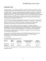
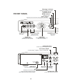
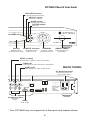
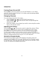
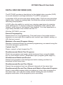
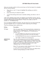
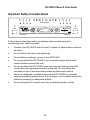
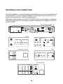
SEASIDE TV
DCT 6400 HD DVR
Wiring Instructions
Additional Information
Digital Cable Box
USER MANUAL
interactive digital communications
INFO
MENU
A/B
GUIDE
SMART CARD
POWER
USB
VIDEO IN
DVR/HDTV Capable
L AUDIO IN R
SELECT
CAUTION
RISK OF ELECTRIC SHOCK
DO NOT OPEN
CAUTION: TO REDUCE THE RISK OF ELECTRIC SHOCK,
DO NOT REMOVE COVER (OR BACK).
NO USER-SERVICEABLE PARTS INSIDE.
REFER SERVICING TO QUALIFIED SERVICE PERSONNEL.
Graphical Symbols and supplemental warning marking locations on bottom of terminal.
WARNING
TO REDUCE THE RISK OF FIRE OR SHOCK, DO NOT EXPOSE THIS
APPLIANCE TO RAIN OR MOISTURE.
CAUTION
TO PREVENT ELECTRICAL SHOCK, DO NOT USE THIS (POLARIZED) PLUG
WITH AN EXTENSION CORD, RECEPTACLE, OR OTHER OUTLET UNLESS
THE BLADES CAN BE FULLY INSERTED TO PREVENT BLADE EXPOSURE.
The lightning flash with arrowhead symbol, within an equilateral triangle, is
intended to alert the user to the presence of uninsulated “dangerous voltage”
within the product’s enclosure that may be of sufficient magnitude
to constitute a risk of electric shock to persons.
The exclamation point, within an equilateral triangle, is intended to alert the
user to the presence of important operating and maintenance (servicing)
instructions in the literature accompanying the appliance.
IMPORTANT SAFETY INSTRUCTIONS
1
Read instructions
All the safety and operating instructions should be read before the digital cable box is operated.
2
Retain instructions
The safety and operating instructions should be retained for future reference.
3
Heed warnings
All warnings on the digital cable box and in the operating instructions should be adhered to.
4
Follow instructions
All operating and use instructions should be followed.
5
Cleaning
Unplug this product from the wall outlet before cleaning. Do not use liquid cleaners or ae rosol
cleaners. Use a damp cloth for cleaning.
6
Attachments
Do not use attachments not recommended as they may cause hazard.
7
Water and moisture
Do not use this equipment near water; for example, near a bathtub, wash bowl, kitchen sink, or
laundry- tub, in a wet basement, or near a swimming pool, and the like.
8
Accessories
Do not place this product on an unstable cart, stand, tripod, bracket, or table. The product may fall
causing serious injury and serious damage to the appliance. Use only with a cart, stand, tripod,
bracket, or table recommended by the manufacturer, or sold with the equipment. Any mounting of
the appliance should follow the manufacturer’s instructions, and should use a mounting accessory
recommended by the manufacturer.
9
Ventilation
Slots and openings in the cabinet are provided for ventilation and to ensure reliable operation of
the equipment and to protect it from overheating. The openings should never be blocked by
placing the product on a bed, sofa, rug, or similar surface. Equipment should never be placed near
or over a radiator or heat register, or in a built- in installation such as a bookcase or rack unless
proper ventilation is provided.
10
Power sources
This product should be operated only from the type of power sources indicated on the mar king
label. If you are not sure of the type of power supplied to your home, consult your local power
company. For equipment intended to operate from battery power, or other sources, refer to the
operating instructions.
11
Ground or polarization
This equipment may be equipped with a polarized alternating - current line plug (a plug having one
blade wider than the other). This plug will fit into the power outlet only one way. This is a safety
feature. If you are unable to insert the plug fully into the outlet, try reversing the plug. If the plug
should still fail to fit, contact your electrician to replace your obsolete outlet. Do not defeat the
safety purpose of the polarized plug.
12
Alternate warnings
This equipment may be equipped with a 3 - wire grounding - type plug , a plug having a third
(grounding) pin. This pin will only fit into a grounding - type power outlet. This is a safety feature. If
you are unable to insert the plug into the outlet, contact your electrician to replace your obsolete
outlet. Do not defeat the safety purpose of the grounding - type plug.
13
Power cord protection
Power supply cords should be routed so that they are not likely to be walked on or pinched by
items placed upon or against them, paying particular attention to cords at plugs, convenience
receptacles, and the point where they exit from the appliance.
IMPORTANT SAFETY INSTRUCTIONS
14
Outdoor Cable Grounding
Ensure the cable system is grounded as to provide some protection against voltage surges and
built-up static charges.
15
Lightning
For added protection for this equipment during a lightning storm, or when it is left unattended and
unused for long periods of time, unplug it from the wall outlet and disconnect the cable system.
This will prevent damage to the video product due to lightning and power line surges.
16
Overloading
Do not overload wall outlets and extension cords as this can result in a risk of fire or electrical
shock.
17
Object and liquid entry
Never push objects of any kind into this equipment through openings, as they may touch
dangerous voltage points or short - out parts that could result in a fire or electrical shock. Never spill
liquid of any kind on the product.
18
Servicing
Do not attempt to service this equipment yourself, as opening or removing covers may expose you
to dangerous voltage or other hazards, return to Seaside Communications for replacement.
19
Safety check
Upon completion of any service to this digital cable box, ask the Seaside service technician to
perform safety checks to determine that the product is in proper operational condition.
20
Heat
This digital cable box should be situated away from heat sources such as radiators, heat registers,
stoves, or other products (including amplifiers) that produce heat.
CANADIAN COMPLIANCE
This Class B digital apparatus meets all requirements of the Canadian Interference - Causing
Equipment Regulations. Cet appareil numérique de la classe B respects toutes les exigences du
Règlement sur le matériel brouilleur du Canada.
www.ic.gc.ca/eic/site/ic1.nsf/eng/home
www.ic.gc.ca/eic/site/ic1.nsf/fra/accueil
Disclaimer
The information in this document is carefully examined, and is believed to be entirely reliable. However, no
responsibility is assumed for inaccuracies. Furthermore, Seaside Communications reserves the right to make
changes herein to improve readability, function, or design.
Motorola Computer Software Copyrights
The Motorola product described in this manual may include copyrighted Motorola computer programs stored
in semiconductor memories or other media. Laws in the United States and other countries preserve for
Motorola certain exclusive rights for copyrighted computer programs, including, but not limited to, the
exclusive right to copy or reproduce in any form the copyrighted computer program. Accordingly, any
copyrighted Motorola computer programs contained in the Motorola products described in this manual may
not be copied, reproduced, modified, reverse-engineered, or distributed in any manner without the express
written permission of Motorola. Furthermore, the purchase of Motorola products shall not be deemed to grant
either directly or by implication, estoppel, or otherwise, any license under the copyrights, patents or patent
applications of Motorola, except for the normal non-exclusive license to use that arises by operation of law in
the sale of a product.
Motorola, Inc.
www.motorola.com
MOTOROLA and the Stylized M Logo are registered in the U.S. Patent and Trademark Office.
All other product or service names are the property of their respective owners. © Motorola, Inc. 2010
DCT6400 Phase III User Guide
CONTENTS
Introduction .............................................................................................3
Operation .................................................................................................6
Turning Power On and Off............................................................... 6
Changing Channels ..........................................................................6
Adjusting the Volume.......................................................................6
Interactive Program Guide............................................................... 6
Digital Video Recorder (DVR)................................................................. 7
Optimizing Your DCT6400 For High Definition TV............................... 8
On-Screen Graphics .............................................................................12
Connecting Your DCT6400...................................................................13
Video Connection Options ............................................................14
Important Safety Considerations ..................................................15
Connecting Your DCT6400 to aN HDTV – Video Only....................... 16
Connecting HDTV – Video Only ....................................................17
Connecting Your DCT6400 to a HDTV – Audio Only ......................... 18
Connecting HDTV – Audio Only....................................................19
Connecting Your DCT6400 to an A/V Receiver – Audio Only........... 20
Connecting an A/V Receiver – Audio Only .................................. 21
Connecting Your DCT6400 to a Stereo TV ........................................22
Connecting a Stereo TV .................................................................23
Connecting Your DCT6400 to a Stereo TV and Stereo VCR ............ 24
Connecting a Stereo TV and Stereo VCR.....................................25
Connecting Your DCT6400 to an A/V Receiver, TV, and VCR ......... 26
Connecting an A/V Receiver, TV, and VCR.................................. 27
1
Recording Your Connections ..............................................................28
Data Devices ..........................................................................................29
Troubleshooting....................................................................................30
2
DCT6400 Phase III User Guide
INTRODUCTION
Congratulations on receiving a Motorola DCT6400 Series Phase III High
Definition Advanced DVR Cable Box. Motorola has merged the features
of digital cable – the seemingly endless programming options, interactive
program guide, Seaside video on demand (VOD), and commercial free,
diital quality music – with the flexibility of a dual tuner digital video recorder
(DVR) and the incredible picture quality and sound of high definition TV.
HDTV provides up to twice the color resolution and up to six times the
sharpness of standard definition TV.
The DCT6400 enables a high quality connection to consumer audio and
video devices through the HDMI and Component interfaces. It contains a
hard drive for hours of DVR functionality, including recording high
definition (HD) programs and watch and record functionality.
This User Guide introduces the basic features, outlines important
safeguards, and provides options for integrating your DCT6400 into your
entertainment system. Please take a few moments to read through this
User Guide. The configuration diagrams, on-screen menu description,
and troubleshooting section will help you make the most of your home
entertainment experience.
In this guide, “DCT6400” refers to all DCT6400 Series Phase III cable
terminals, including the DCT6412 and DCT6416. They function
identically, but have different size hard drives.
For example:
Estimated Recording Hours For
Model
Drive
Size
DCT6412
DCT6416
Analog
Channels
Standard Digital
Channels
HDTV
Channels
120 GB
24 to 32
38 to 73
10 to 15
160 GB
35 to 43
55 to 100
14 to 21
All times are approximate. The actual hours you can record depends on
multiple factors.
3
Message Indicator
Lights when message is waiting
POWER switch
Turns unit on or off
FRONT PANEL
MENU switch
Displays menu
INFO switch
Displays current channel and program information
C URSO R
INFO
M SG S.
M ENU
ON
PO WER
USB 2 0
VDEO IN
L AUD O IN R
Du a l u n e r DVR / HDTV C a p a b le
USB 2.0
Connector
AUDIO IN (L/R)*
POWER indicator
Lights when
unit is on
Audio input from
CD player or tuner
VIDEO IN*
CURSOR
Video input from VCR,
camcorder, or other device
Moves cursor around guide
and menu screens
AUDIO IN (R/L)*
Audio input from CD player or tuner
OPTICAL SPDIF
Provides Dolby Digital 5.1 audio or PCM audio
®
OPTICAL
SPD F
R
AUDIO
N
L
RF OUT
CABLE
N
CABLE IN
Input from cable provider
IR
Enables you to control VCR
while recording selected program
(Not supported by all program guides)
4
R
RF OUT
Output to TV
S-V DEO
R AUDIO
OUT
L
S-VIDEO
Output to
TV or VCR
AUDIO OUT (R/L)
Audio output to stereo receiver
DCT6400 Phase III User Guide
RECORD Indicator
Lights when DVR is recording
SELECT switch
Selects menu options
GUIDE switch
Displays program guide
OPTION switch
Reserved
CH AN N EL
O PTIO N
RECO RD
G UIDE
SM ART CARD
REM OTE
SELECT
DCT6400 III
Display
REMOTE indicator
Displays channel
number and time of day
Lights when remote
control is in use
CHANNEL
Scrolls up or down
through the channels
SMART CARD*
Supports Smart Card
functionality
SPDIF (coaxial)
®
Provides Dolby Digital 5.1 audio or PCM audio
VIDEO IN*
Video input from VCR, camcorder, or other device
BACK PANEL
VIDEO OUT
Video output to TV, VCR, or other device
AC Switched Outlet
Provides AC power to TV,
VCR, or other device
SPDIF
V DEO
IN
OUT
SWITCHED
105-125V
60Hz
4A MAX
500W MAX
HDMI
Y
Pb
Pr
Component Video
HDTV video
output
HDMI
HDTV output
* Your DCT6400 may not support all of the inputs and outputs shown.
5
OPERATION
Turning Power On and Off
Press POWER on the front panel to turn the DCT6400 on or off. When
using the remote control, be sure it is in cable mode by pressing CABLE
before pressing POWER.
Changing Channels
You can change channels in two ways:
•
Press CHANNEL
or
on the DCT6400 front panel, or
press CHANNEL or on the remote control to step through the
channel selection.
•
Enter the number of the channel you wish to view using the number
keys on the remote control.
Adjusting the Volume
Press VOLUME or on the remote control to adjust the volume. When
you adjust the volume, the volume scale is displayed on the screen.
Press MUTE on the remote control to turn the sound off and on again.
For best audio quality, use the remote control to set the DCT6400 to
approximately ¾ of the maximum volume level and then adjust the audio
levels on external devices such as your TV or A/V Receiver.
Interactive Program Guide
The interactive program guide (IPG) displays information about TV
programs and enables you to access features such as Parental Control
or Pay-Per-View. IPGs can vary with each cable service provider. Refer
to your IPG manual for detailed instructions.
6
DCT6400 Phase III User Guide
DIGITAL VIDEO RECORDER (DVR)
The DCT6400 contains a hard drive for the digital video recorder (DVR)
to record standard- and high-definition TV (HDTV) programs.
A standard VCR records and plays analog video. DVR records and plays
digital video. Unlike an analog tape, the hard drive allows simultaneous
recording and playback.
A DVR offers the ability to control your viewing experience by pausing
(time shifting) live TV and providing trick playback modes (pause, fast
forward, slow forward, fast rewind, slow rewind). You may experience a
slight delay between time shifted and live TV.
With the DCT6400, you can:
Record Programming
Record hours of TV programming. The total hours of recorded content
depends on your hard drive capacity and content type (digital, analog, or
HD) that you record.
Maintain a Personal Program Library
Maintain a personal library of recorded programming, accessed using the
interactive program guide (IPG).
Control Live TV
Pause, rewind, or fast-forward live TV.
Simultaneously Watch Two Programs
Watch two programs and easily switch between them using the SWAP
key on your remote control. (Dependent upon program guide support.)
Simultaneous Watch and Record
Record one program in the background while viewing another live
broadcast at the same time.
Simultaneously Record Two Shows
Record two programs from two different channels at the same time.
Simultaneously Record Two Shows and Watch a Recorded Program
Watch a recorded program while recording up to two other programs at
the same time. You can also easily switch viewing the pre-recorded
program and either of the programs you’re recording.
7
OPTIMIZING YOUR DCT6400 FOR HIGH DEFINITION TV
The DCT6400 outputs HD video through its Y Pb Pr (component), HDMI
connectors. This section describes how to optimize standard and HD
video based on your HDTV and personal preferences.
For a TV with an HDMI connection, be sure the TV is on and connected
to the DCT6400 HDMI OUT connector before adjusting the settings.
Motorola recommends using HDMI cables less than 20 meters long.
You can configure the TV type, HDMI and/or Y Pb Pr video output, and
closed captioning.
To optimize the output settings:
1
Be sure your DCT6400 is plugged into a power outlet and
connected to your TV.
2
Power off the DCT6400 and then immediately press the MENU key
on the front panel. If your TV is on, the on-screen menu lists the
settings you can configure:
USER SETTINGS
>
TV TYPE
HDMI/YpbPr OUTPUT
4:3 OVERRIDE
16:9
1080I
480I
CLOSED CAPTION
SERVICE SELECTION
ANALOG
DIGITAL
FONT SIZE
FONT COLOR
FONT OPACITY
FONT EDGE TYPE
FONT EDGE COLOR
BACKGROUND COLOR
BACKGROUND OPACITY
SETTINGS
RESTORE ALL DEFAULTS
DISABLED
CC1
PRIMARY LANGUAGE
AUTO
AUTO
AUTO
AUTO
AUTO
AUTO
AUTO
AUTO
8
DCT6400 Phase III User Guide
Use your remote control or the cursor keys on the front panel to navigate
the on-screen display:
•
Press the ▲ and ▼ keys to highlight the setting you wish to
change.
•
Press the ► key to select an option.
•
To exit the setting and move to another setting, use the ▲ and ▼
keys.
If the User Settings menu does not display on the HDTV screen, the TV
may not support the default video output setting. Use the front panel LED
to adjust the settings as described in “There is no video on the TV
screen” in “Troubleshooting.”
For a TV with an HDMI connection, be sure the TV is on and connected
to the DCT6400 HDMI OUT connector before adjusting the settings.
The User Settings menu options are:
Setting
Description
TV Type
Sets the aspect ratio. The front panel display indicates the
type you select. Defaults to 16:9. Options are 16:9 for wide
screen TVs or 4:3 LETTERBOX or 4:3 PAN/SCAN for
standard TVs:
HDMI/YPbPr
Output
•
4:3 LETTERBOX fits widescreen programming on the
screen by placing black bars at the top and bottom.
•
4:3 PAN/SCAN fills the screen by cropping the left and
right edges of widescreen programming.
Sets the video display format for the HDMI or component
video outputs. The front panel display indicates the format
you select. Defaults to 1080i. Options are 1080i, 720p, 480p,
or 480i. For HDMI only, additional options you can use to
display video on a computer monitor are PC1-VGA
(640x480) and PC2-XVGA (800x600).
Some TVs only support certain display formats. Check your
TV user manual for more information.
If you are not using the HDMI connection, the HDMI/YPbPr
OUTPUT setting displays as YPbPr OUTPUT.
9
Setting
Description
4:3 Override
Sets the display format for 4:3 standard-definition
programming. If the YPbPr Output is set to 1080i, 720p, or
480p, this setting defaults to 480i. If the YPbPr Output is set
to 480i, this setting defaults to OFF and cannot be changed.
Options are:
•
OFF displays non-high-definition programs having a 4:3
aspect ratio in wide screen format. On an HDTV, black
bars display on the left and right of the picture. Selecting
OFF for a 4:3 TV may result in a small picture with black
bars around it.
•
480i displays non-high-definition programs in their
original 480i format. Some TVs cannot display 480i
format on their component video inputs (YPbPr). Check
the TV user manual for more information.
•
480p converts non-high-definition TV programs to a
higher-quality 480p format. Some TVs cannot display
480p format on their component video inputs (YPbPr).
Check the TV user manual for more information.
•
Stretch automatically stretches all standard definition
programming to fill your widescreen display. Stretch can
only be selected if you have TV Type set to 16:9.
Closed Caption
Turns closed captions off or on. The front panel display
indicates the status of the closed captions. Defaults to
DISABLED. Options are ENABLED or DISABLED.
Closed Caption
Turns closed captions off or on. The LED panel displays the
status of the closed captions. Defaults to DISABLED.
Options are ENABLED or DISABLED.
Service
Selection
Sets the service used for closed captions:
•
Analog: CC1, CC2, CC3, CC4, T1, T2, T3, or T4. The
default is CC1.
•
Digital: PRIMARY LANGUAGE, SECONDARY
LANGUAGE, 3, 4, 5, or 6. The default is PRIMARY
LANGUAGE.
Font Size
Sets the font size for closed captions. Defaults to AUTO.
Options are AUTO, STANDARD, LARGE, or SMALL.
Font Style
Sets the font style. Defaults to AUTO. Options are AUTO,
MONO SERIF, PROPORTION SERIF, MONO NO SERIF,
PROPORTION NO SERIF, CASUAL, CURSIVE, or SMALL.
10
DCT6400 Phase III User Guide
Setting
Description
Font Color
Sets the font color. Defaults to AUTO. Options are AUTO,
WHITE, BLACK, RED, GREEN, BLUE, YELLOW,
MAGENTA, or CYAN.
Font Opacity
Sets the opacity. Defaults to AUTO. Options are AUTO,
TRANSPARENT, TRANSLUCENT, SOLID, or FLASHING.
Font Edge Type
Sets the edge appearance — AUTO, NONE, RAISED,
DEPRESSED, UNIFORM, LEFT SHADOWED, or RIGHT
SHADOWED. The default is AUTO.
Font Edge Color
Sets the edge color — AUTO, WHITE, BLACK, RED,
GREEN, BLUE, YELLOW, MAGENTA, or CYAN. The default
is AUTO.
Background
Color
Sets the background color for closed captions. Defaults to
AUTO. Options are AUTO, WHITE, BLACK, RED, GREEN,
BLUE, YELLOW, MAGENTA, or CYAN.
Background
Opacity
Sets the background opacity for closed captions. Defaults to
AUTO. Options are AUTO, TRANSPARENT,
TRANSLUCENT, SOLID, or FLASHING.
Settings
Sets the default settings for closed captions (AUTO) or the
settings you have configured (USER). Defaults to AUTO.
Options are AUTO or USER.
Restore All
Defaults
To reset all User Settings to their defaults, select this option
and press the ► key.
For HDMI only, when you first connect a TV to the DCT6400
using the HDMI connection, the TV and the DCT6400
exchange information to automatically determine the best
possible TV TYPE and HDMI/YPbPr OUTPUT settings. You
can change these settings at any time:
•
To cause the HDMI TV and DCT6400 to re-exchange
information to restore the automatic settings, select
Restore All Defaults with the HDMI connection in place
and the TV powered on.
•
If you connect another HDMI TV to the DCT6400, select
Restore All Defaults. This causes the TV and DCT6400
to exchange information, enabling settings suited to your
new TV.
To exit the menu and save your settings, press the POWER or MENU key.
11
ON-SCREEN GRAPHICS
The DCT6400 can generate on-screen graphics that overlay the video
programming or fill the entire television screen. Common examples
include on-screen menus (such as the User Setting menu), closed
captions, and interactive program guides. The DCT6400 overlays these
graphics whenever you display a menu, enable closed captions, or scroll
through a program grid.
On-screen graphics are available for all DCT6400 video outputs.
12
DCT6400 Phase III User Guide
CONNECTING YOUR DCT6400
This section describes connecting the DCT6400 to your home
entertainment system.
Instructions and diagrams are included for connections to:
•
High definition television (HDTV)
•
A/V Receiver – Audio
•
Stereo TV
•
Stereo TV and Stereo VCR
•
A/V Receiver, TV, and VCR
Before you move or change components on your entertainment system,
review the following:
•
For basic cable connections, use 75-ohm coaxial cables equipped
with F-type connectors.
•
Disconnect power from the cable terminal before connecting or
changing cable connections.
For information on connecting for HDTV, see “Video Options” on the next
page.
CAUTION!
Do not place anything on top of the cable terminal, especially other home
entertainment components. Be sure to provide adequate ventilation to
prevent overheating.
13
Video Connection Options
The DCT6400 offers the following video outputs:
HDTV
Component Video, HDMI
Standard
Composite Video, S-Video, or RF coaxial.
To determine the available inputs on your TV, check the manual supplied
with the TV or the TV itself.
Use the following guidelines to determine the best video connection for
your home entertainment system:
Component video (Y Pb Pr) – HDTV and standard
The Y Pb Pr connectors on your DCT6400 provide component
video, which is the most widely supported HDTV connection.
HDMI – HDTV and standard
HDMI offers higher video quality than component video. If your TV
has an HDMI input, use the HDMI connection on your DCT6400.
Motorola recommends using HDMI cables less than 20 meters long.
HDMI is compatible with DVI. If your TV has a DVI input, you can
use an HDMI-to-DVI converter cable to connect to the DCT6400
HDMI connector. Seperate audio cable(s) are required when using
HDMI to DVI.
S-Video – standard only
If your TV has an S-Video input, use S-Video. S-Video is the
highest quality standard-definition video output on the DCT6400.
Composite video – standard only
If your TV does not have an S-Video input, use the composite
video (VIDEO) output.
RF coaxial – standard only
If your TV only has a coaxial RF input, connect it to the DCT6400
RF OUT connector.
14
DCT6400 Phase III User Guide
Important Safety Considerations
V E N T I L A T E
2 inch space
2
2
inch
inch
SS
S
S
SB
0
V
DCT6 16 II
Dual ue D R HD VCa pa be
Follow these important safety guidelines when positioning and
connecting your cable terminal:
•
Position the DCT6400 with at least 2 inches of space above and on
all sides
•
Do not block the slots and openings
•
Do not place anything on top of the DCT6400
•
Do not position the DCT6400 in an enclosed space that would
restrict airflow around the unit
•
Do not position the DCT6400 near any external heat source that
could raise the temperature around the unit. Do not place the
terminal on top of another heat-producing electronic device.
•
Allow for adequate ventilation around the DCT6400 to maintain
normal operating temperature. Do not place it in a sealed enclosure
without providing for adequate airflow.
•
Do not plug the AC power cord into a switched power outlet.
15
CONNECTING YOUR DCT6400 TO AN HDTV – VIDEO ONLY
HDMI
connection
Component video
connection
DCT6400 Phase III
OPTICAL
SPDIF
R
AUDIO
IN
L
SPDIF
RF OUT
VIDEO
N
OUT
HDMI
CABLE
IN
R
IR S V DEO
AUDIO L
OUT
Y
Pb
Pr
SWITCHED
105-125V
60Hz
A MAX
500W MAX
Cable in
Either / or
HDTV
Co m p o n en t
Vid eo In p u t
HDM I
CABL E/
AN ENNA IN
Y
Pb
IEEE 1394
Pr
16
DCT6400 Phase III User Guide
Connecting HDTV – Video Only
1
Connect an RF coaxial cable to the cable wall outlet and the
CABLE IN connector on the DCT6400.
2
Connect the HDTV using component video, HDMI.
Component video (Y Pb Pr)
Connect the component video cables to the Y, Pb, and Pr connectors on
your DCT6400 and the HDTV.
This connection carries video only. To connect the audio connections for
your HDTV, refer to the following page. To connect your audio
connections for a home theater receiver, refer to “Connecting Your
DCT6400 to an A/V Receiver – Audio Only.”
HDMI
If your HDTV has a HDMI input, connect an HDMI cable less than 20
meters long to the HDMI OUT connector on your HDTV and the DCT6400.
If you use the TV as the primary audio source or your home theater
receiver has an HDMI input and output, the HDMI connection carries
video and audio.
If your TV has a DVI input, you can use an HDMI-to-DVI converter cable
to connect to the DCT6400 HDMI connector.
For information on configuring your DCT6400 settings, see “Optimizing
Your DCT6400 for High Definition TV.”
17
CONNECTING YOUR DCT6400 TO A HDTV – AUDIO ONLY
Audio
connection
Optical SPDIF
connection
SPDIF audio
connection
DCT6400 Phase III
OPTICAL
SPDIF
R
AUD O
N
L SPD F
RF OUT
VIDEO
IN
OUT
HDMI
CABLE
IN
R
R S-VIDEO
AUD O L
OUT
Y
Pb
Pr
SWITCHED
105-125V
60Hz
A MAX
500W MAX
Cable in
Either / or
HDTV
INPU
DIGI AL NPU
COAX
CABL E/
AN ENNA IN
OP CAL
SPDIF
AUD O L EF
AUD O R GH
18
DCT6400 Phase III User Guide
Connecting HDTV – Audio Only
Connect the stereo audio cable to the AUDIO R and L connectors on the
DCT6400 and the corresponding connectors on the HDTV.
If your equipment supports it, use the OPTICAL SPDIF or coaxial digital
SPDIF outputs instead of the AUDIO R and L outputs. In most cases,
S/PDIF offers better audio quality, including support for Dolby 5.1
Surround Sound.
HDMI carries video and audio. If you connect the DCT6400 to your
HDTV using HDMI, no additional audio connections to the TV are
necessary.
For information on configuring your DCT6400 settings, see “Optimizing
Your DCT6400 for High Definition TV.”
19
CONNECTING YOUR DCT6400 TO AN A/V RECEIVER – AUDIO ONLY
Audio
connection
SPDIF audio Optical SPDIF
connection
connection
DCT6400 Phase III
OPTICAL
SPDIF
R
AUD O
N
L SPD F
RF OUT
VIDEO
IN
OUT
HDMI
CABLE
IN
R
R S-VIDEO
AUD O L
OUT
Y
Pb
Pr
SWITCHED
105-125V
60Hz
A MAX
500W MAX
Either / or
R
AUD O
L
VIDEO
VIDEO
S VIDEO
DIGI AL NPU
COAX
DVD
CABL E/ V
OP ICAL
V DEO 2
V/M ONI OR
OU PU
SPEAKER
CONNEC ORS
IN
VIDEO S VIDEO
VCR
OU
A/V receiver
20
DCT6400 Phase III User Guide
Connecting an A/V Receiver – Audio Only
The audio connections options to your A/V receiver or home theater
receiver are:
•
Optical SPDIF: Connect the optical SPDIF cable to the OPTICAL
SPDIF connector on the DCT6400 and the corresponding connector
on the A/V receiver.
•
Coaxial SPDIF: Connect the digital audio cable to the SPDIF
connector on the DCT6400 and the corresponding connector on
the A/V receiver.
•
Stereo audio R and L: Connect the stereo audio cable to the
AUDIO R and L connectors on the DCT6400 and the corresponding
connectors on the A/V receiver.
If you’re A/V receiver supports it, use the OPTICAL SPDIF or coaxial SPDIF
outputs on the DCT6400 instead of its stereo AUDIO R and L outputs. In
most cases, S/PDIF offers better audio quality, including support for
Dolby 5.1 Surround Sound.
For information on configuring your DCT6400 settings, see “Optimizing
Your DCT6400 for High Definition TV.”
21
CONNECTING YOUR DCT6400 TO A STEREO TV
RF (75 ohm)
connection
S-Video
connection
Video
connection
Audio
connection
DCT6400 Phase III
OPT CAL
SPD F
R
AUDIO
IN
L SPDIF
RF OUT
VIDEO
N
OUT
SWITCHED
105-125V
60Hz
A MAX
500W MAX
HDMI
CABLE
IN
R
IR S-VIDEO
AUDIO L
OUT
Y
Pb
Pr
Cable in
Stereo TV
Either / or
INPU
S VIDEO
VIDEO
CABL E/
AN ENNA N
AUDIO L EF
AUDIO RIGH
Depending on the TV’s inputs:
1
If possible, use the S-VIDEO and AUDIO connectors on the DCT6400.
2
If the TV has no S-Video input, use the composite VIDEO and AUDIO
connectors on the DCT6400.
3
If the TV has an RF input only, use the RF OUT connector on the
DCT6400. The RF connection carries video and audio.
22
DCT6400 Phase III User Guide
Connecting a Stereo TV
1
Connect an RF coaxial cable to the cable wall outlet and the
CABLE IN connector on the DCT6400.
2
Connect the stereo audio cable to the AUDIO R and L connectors on
the DCT6400 and the corresponding connectors on the stereo TV.
3
Connect an S-video cable to the S-VIDEO connectors on the
DCT6400 and the TV.
or
Connect a video cable to the VIDEO OUT connector on the DCT6400
and the VIDEO IN connector on the TV.
OR
1
Connect an RF coaxial cable to the cable wall outlet and the
CABLE IN connector on the DCT6400.
2
Connect an RF coaxial cable to the RF OUT connector on the
DCT6400 and the RF connector on the TV.
This video connection method does not support HD video. For more
information, see “Connecting Your DCT6400 to an HDTV – Video Only.”
23
CONNECTING YOUR DCT6400 TO A STEREO TV AND STEREO VCR
RF (75 ohm)
connection
Video
connection
Audio
connection
DCT6400 Phase III
OPTICAL
SPDIF
R
AUDIO
IN
L
SPDIF
RF OUT
VIDEO
IN
OUT
HDMI
R
IR S-VIDEO
CABLE
IN
AUDIO L
OUT
Y
Pb
Pr
SWITCHED
105-125V
60Hz
A MAX
500W MAX
Cable in
Stereo VCR
Stereo TV
INPU
INPU
CABL E/
AN ENNA IN
o
AUDIO
S V DEO
OU PU
VIDEO
AUDIO
VIDEO
V DEO
CABL E/
AN ENNA IN
V
R
L
R
L
AUDIO L EF
AUDIO RIGH
24
DCT6400 Phase III User Guide
Connecting a Stereo TV and Stereo VCR
1
Connect an RF coaxial cable to the cable wall outlet and the
CABLE IN connector on the DCT6400.
2
Connect a stereo audio cable to the AUDIO OUT R and L connectors
on the DCT6400 and the INPUT AUDIO R and L connectors on the
stereo VCR.
3
Connect a video cable to the VIDEO OUT connector on the DCT6400
and the INPUT VIDEO connector on the stereo VCR.
4
Connect a stereo audio cable to the OUTPUT AUDIO R and L
connectors on the stereo VCR and the INPUT AUDIO RIGHT and LEFT
connectors on the stereo TV.
5
Connect a video cable to the OUTPUT VIDEO connector on the stereo
VCR and the INPUT VIDEO connector on the stereo TV.
This video connection method does not support HD video. For more
information, see “Connecting Your DCT6400 to an HDTV – Video Only.”
25
CONNECTING YOUR DCT6400 TO AN A/V RECEIVER, TV, AND VCR
RF (75 ohm)
connection
Video
connection
Audio
connection
Optical SPDIF
connection
DCT6400 Phase III
OPTICAL
SPD F
R
AUDIO
N
L SPDIF
RF OUT
V DEO
N
OUT
SWITCHED
105 125V
60Hz
A MAX
500W MAX
HDMI
R
IR S-VIDEO
CABLE
IN
AUDIO L
OUT
Y
Pb
Pr
Cable in
Stereo VCR
Stereo TV
NPU
INPU
CABL E/
AN ENNA N
o
AUD O
S VIDEO
OU PU
VIDEO
AUDIO
VIDEO
V DEO
R
L
R
AUD O L EF
CABL E/
AN ENNA N
V
L
AUD O RIGH
A/V receiver
R
AUD
L
V DEO
VIDEO
S VIDEO
DIGI AL INPU
COAX
DVD
OP
CABL E/ V
CAL
VIDEO 2
V/M ONI OR
OU PU
IN
VCR
VIDEO S V DEO
OU
26
SPEAKER
CONNEC ORS
DCT6400 Phase III User Guide
Connecting an A/V Receiver, TV, and VCR
1
Connect an RF coaxial cable to the cable wall outlet and the
CABLE IN connector on the DCT6400.
2
Connect a stereo audio cable to the AUDIO OUT R and L connectors
on the DCT6400 and the INPUT R and L connectors on the
A/V receiver.
3
Connect a video cable to the VIDEO OUT connector on the DCT6400
and the CABLE/TV VIDEO connector on the A/V receiver.
4
Connect a stereo audio cable to the VCR AUDIO OUT R and L
connectors on the A/V receiver and the INPUT AUDIO R and L
connectors on the stereo VCR.
5
Connect a stereo audio cable to the OUTPUT AUDIO OUT R and L
connectors on the stereo VCR and the VCR AUDIO IN R and L
connectors on the A/V receiver.
6
Connect a video cable to the INPUT VIDEO connector on the stereo
VCR and the VIDEO VCR OUT connector on the A/V receiver.
7
Connect a video cable to the OUTPUT VIDEO connector on the stereo
VCR and the VIDEO VCR IN connector on the A/V receiver.
8
Connect a video cable to the INPUT VIDEO connector on the stereo
TV and the TV/MONITOR OUTPUT video connector on the A/V
receiver.
If you can:
•
Use the OPTICAL SPDIF or coaxial SPDIF outputs instead of the stereo
AUDIO R and L outputs. In most cases, S/PDIF offers better audio
quality, including support for Dolby 5.1 Surround Sound.
•
Use the S-video connections instead of the standard RCA video
connections. In most cases, S-video offers better video quality.
This video connection method does not support HD video. For more
information, see “Connecting Your DCT6400 to an HDTV – Video Only.”
27
RECORDING YOUR CONNECTIONS
Use this diagram to record connections between your home entertainment
components. You can use this diagram to reconnect your system if you
move the equipment or add new equipment.
Disconnect the power from the DCT6400 before connecting or changing
cable connections. Do not place another component or object on top of
the DCT6400.
DCT6400 Phase III
OPT CAL
SPD F
R
AUDIO
IN
L
SPDIF
RF OUT
VIDEO
IN
OUT
SWITCHED
105-125V
60Hz
A MAX
500W MAX
HDMI
CABLE
N
IR S-VIDEO
R
AUDIO L
OUT
Y
Pb
Pr
TV
VCR
CABL E/
AN ENNA IN
INPU
CABL E/
AN ENNA IN
AUDIO
L /M ONO
OU PU
V DEO
AUDIO
OP ICAL
SPDIF
SPDIF
DVI HD V
R
VIDEO
R
L
Y
o
V
R
L
R
AUD O IN
V DEO N
S VIDEO IN
AUDIO OU
VIDEO OU
S VIDEO OU
HDM I
Pb
L
Pr
Stereo receiver
R
DVD
L
CD N
AUDIO OU
SPEAKER
CONNEC ORS
AUX IN
COAX
N
OP ICAL
D GI AL
APE 1
V DEO OU
R
L
ANAL OG
OU
A/V receiver
R
AUDIO
L
V DEO
VIDEO
S VIDEO
DIGI AL INPU
COAX
DVD
OP ICAL
CABL E/ V
V DEO 2
V/M ONI OR
OU PU
IN
VCR
VIDEO S VIDEO
OU
28
SPEAKER
CONNEC ORS
V DEO
S VIDEO
DCT6400 Phase III User Guide
DATA DEVICES
DCT6400 Phase III
OPTICAL
SPDIF R
AUD O
IN
L SPDIF
RF OUT
VIDEO
IN
ETHERNET
OUT
HDMI USB
CABLE
N
R
IR S-VIDEO
AUD O L
OUT
Y
Pb
SATA
EEE
139
Pr
SWITCHED
105-125V
60Hz
A MAX
500W MAX
V PASS CARD
Ethernet, SATA, USB and IEEE1394 are currently not supported by
Seaside Communications.
29
TROUBLESHOOTING
Before calling Seaside Commnications, review this troubleshooting guide.
This information is to help you quickly solve a problem. If your problem
still exists, call 539-6250
Problem
Possible Solution
The DCT6400 will
not power on
The DCT6400 may have received a software update and
may not power on while the new software is being
installed. Try again in a few minutes.
Verify that the AC power cord is connected to the DCT6400
and an AC outlet. Unplug the DCT6400 from the AC
outlet, plug it back in, and then press the POWER button.
If the DCT6400 is connected to a switched outlet on
another unit, verify that that unit is powered on.
Press the POWER button on the DCT6400 front panel
instead of the remote control. The batteries in the remote
control may be depleted.
The remote control
does not work
Verify that the remote control is in “Cable” mode.
Verify that there are no obstructions between the remote
control and the DCT6400. Aim the remote control directly
at the DCT6400 front panel, not the TV or VCR.
The angle between the remote control and the DCT6400
may be too large. Stand in front of the DCT6400 and not
too far to either side.
Press and release operation keys one at a time, firmly
and deliberately.
Try changing channels using the buttons on the
DCT6400 front panel.
Check the batteries in the remote control. Install new
batteries if needed.
30
DCT6400 Phase III User Guide
Problem
Possible Solution
There is no audio
when viewing cable
channels
Verify that the MUTE button on the DCT6400 or the
remote control was not pressed. Press MUTE on the
remote control to restore sound.
If the DCT6400 audio output is connected to the TV,
verify that the MUTE button on the TV was not pressed.
If the DCT6400 audio output is connected to a home
theater receiver, verify that the receiver is set to the
appropriate input source and the mute button on the
receiver was not pressed.
Verify that you used the correct audio cables for the ports.
Verify that the audio cables are firmly connected
between the DCT6400 and the audio playback device
(TV, receiver, DVD player, etc.).
There is no audio
from the center
and/or surround
speakers of a home
theater receiver
connected to the
DCT6400
Not all Dolby Digital programs feature full 5.1 surround
sound. In some cases, the programs may only contain
left and right stereo audio.
Verify that the coaxial or optical SPDIF cable is firmly
connected to the DCT6400 and the home theater receiver.
Verify that the home theater receiver is set to a surround
sound audio mode (Dolby Digital, Dolby Pro Logic® II, or
Dolby Pro Logic).
Verify that the receiver is properly configured to work
with all connected speakers.
31
Problem
Possible Solution
There is no video
on the TV screen
Verify that the TV is powered on and set to the
appropriate input source for the DCT6400.
Verify that the DCT6400 is powered on and tuned to an
authorized cable channel.
Verify that all video cables between the DCT6400 and
the TV are firmly connected.
Verify that the coaxial cable feed is firmly connected to
the DCT6400 and the wall jack.
If the DCT6400 is connected to a home theater unit,
verify that the home theater unit is powered on and set to
the appropriate input source.
If the DCT6400 is connected to a TV through its HDMI
connection, power off the TV and then power off the
DCT6400. Wait one second and then power on the
devices.
Not all HDTVs can display every output format (1080i,
720p, 480p, or 480i) available on the DCT6400. To
select a different format:
1
Ensure that your DCT6400 is plugged into a power
outlet and is turned off.
2
Press the MENU key on the front panel. Your
settings are displayed on the DCT6400 front panel
display.
3
Press the ▲ and ▼ keys to display the
HDMI/YPbPr OUTPUT setting.
4
Press the ► key to cycle through the available
output formats until a picture displays on the TV.
No closed captions
display
Verify on the User Settings menu that closed captions
are enabled on the DCT6400.
Verify that closed captions are enabled on the TV.
32
DCT6400 Phase III User Guide
Problem
Possible Solution
There are black
bars to the right
and left of the
picture
Wide screen TVs display 4:3 programs in this format
unless set to Stretch. Turn on the 4:3 OVERRIDE feature
in the User Settings menu. This enables most wide
screen TVs to stretch the video to fill the screen (see
your TV manual for information about stretching 4:3
video).
If the DCT6400 is connected to a wide screen TV, verify
that the TV TYPE is set to 16:9 in the User Settings
menu.
Many HD programs are broadcast in pillar-box format
with black bars to the left and right of the picture. These
programs are broadcast in 16:9 HD formats even though
the video is not 16:9.
There are black
bars above and
below the picture
All 4:3 HDTVs display HD programs in letterbox format
(black bars above and below the picture) because of the
shape of the display screen.
Turn on the 4:3 OVERRIDE feature in the User Settings
menu. This enables most standard screen TVs to display
a full screen picture when the DCT6400 is tuned to a 4:3
program.
Set the TV TYPE to 4:3 Pan-Scan. This enables the
DCT6400 to remove the black bars above and below the
picture when possible.
Some SD programs are broadcast in the letterbox format
with black bars above and below the picture. Some wide
screens TVs offer a zoom feature that may be able to
remove the black bars (see your TV manual for
information about zooming 4:3 video).
33
Problem
Possible Solution
There are black
bars on all four
sides of the picture
This may occur on a 4:3 TV if the 4:3 OVERRIDE setting
is OFF. To set 4:3 SD programming to fill the screen,
depending on the capabilities of the TV, set
4:3 OVERRIDE to 480i or 480p.
This may occur on a 16:9 TV if the active video for an SD
broadcast is in letterbox format. To confirm, wait for a
commercial or look for a graphic, such as a network logo.
If the commercial fills the screen from top to bottom, or
the graphic appears below the active video, the program
is being letterboxed by the broadcaster. You can
minimize this by activating the zoom feature on the TV.
A broadcaster may include black bars on either side of a
wide screen broadcast. This is called a “hybrid” aspect
ratio and results in a black border surrounding the video
on a 4:3 TV. Because this is part of the broadcast, the
DCT6400 cannot correct the video. You may be able to
minimize the border using the zoom feature on the TV.
The DCT6400 is
making a humming
noise.
The DCT6400 includes an integrated hard drive and a
fan for cooling. During normal operation, the DCT6400
emits a low humming noise, similar to a personal
computer. The noise varies in volume occasionally when
the speed of the internal fan adjusts to changes in the
temperature around the DCT6400. Please note the hard
drive will stay on even when the DCT6400 is turned off.
34
www.seaside.ns.ca
539-6250
Office and Studio: 1318 Grand Lake Road
P.O. Box 4558, Reserve Mines, N.S. B1E 1L2