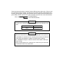
1
R
Version 2.0
Produced in May 2001
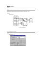
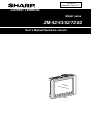
Control Terminal
Model name
ZM-42/43/52/72/82
User's Manual/Hardware version
(ZM-82)
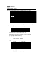
Thank you for purchasing the Control Terminal ZM-42/43/52/72/82 series. Please read
the instruction manual carefully, and operate the product with full understanding of its
functions and operation methods. For the details of each Control Terminal functions or the
panel editing methods, please refer to the instruction manual for the screen edit software.
- ZM-71SE
Instruction Manual
User's Manualt(Tutorial)
Caution
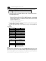
• In this user’s manual, ZM-42/43/52/72/82 series are referred as follows.
Expression in this manual
Series name
ZM-**
ZM-42/43/52/72/82
Note
• We have created this instruction manual carefully, but in case you have
some doubts or comments on this manual, please contact the affiliated
store where you bought this product or directly to our company.
• It is forbidden to copy the content materials of this book, neither partially nor fully.
• Please understand that the content of this manual may be altered for
amelioration without any notifications.
Safety precautions
Read this manual and attached documents carefully before installation, operation, maintenance and
checking in order to use the machine correctly. Understand all of the machine knowledge, safety
information, and cautions before starting to use. In this instruction manual, safety precautions are ranked
into "danger" and "caution" as follows.
Danger
: Wrong handling may possibly lead to death or heavy injury.
Caution
: Wrong handling may possibly lead to medium or light injury.
Even in the case of
Caution , a serious result may be experienced depending on
the circumstances. Anyway, important points are mentioned. Be sure to observe them
strictly.
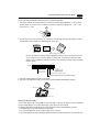
The picture signs of Prohibit and Compel are explained below.
: It means don’ts. For example, prohibition of disassembly is indicated as (
: It means a must. For example, obligation of grounding is indicated as (
).
).
1) Installation
Caution
• Use in the environments specified in the catalog, instruction manual, and user's manual.
Electric shock, fire or malfunction may be caused when used in the environments of high
temperature, high humidity, dusty or corrosive atmosphere, vibration or impact.
• Install according to the manual.
Wrong installation may cause drop, trouble or malfunction.
• Never admit wire chips or foreign matter
Or fire, trouble or malfunction may be caused.
2) Wiring
Compel
• Be sure to ground.
Unless grounded, electric shock or malfunction may be caused.
Caution
• Connect the rated power source.
Connection of a wrong power source may cause a fire.
• Wiring should be done by qualified electrician.
Wrong wiring may lead to fire, trouble or electric shock.
3)
Use
Danger
• Don’t touch the terminal while the power is being supplied or you may have on electric shock.
• Assemble the emergency stop circuit and interlock circuit outside of the ZM-42/43/52/72/82.
Otherwise breakdown or accident damage of the machine may be caused by the trouble of
the ZM-42/43/52/72/82.
4)
Maintenance
Prohibit
• Don’t disassemble or modify the modules.
Or fire, breakdown or malfunction may be caused.
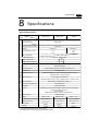
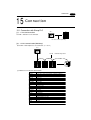
Contents
1. Hardware Specifications
1.
2.
3.
4.
5.
6.
7.
8.
9.
10.
11.
12.
13.
14.
15.
16.
17.
18.
19.
20.
21.
22.
23.
24.
25.
26.
Special Features ........................................................................................................................... 1-1
Notes on Usage ............................................................................................................................. 1-2
System Composition .................................................................................................................... 1-4
Names of Components ................................................................................................................ 1-9
Dimensions and Panel Cut-out ............................................................................................... 1-11
Mounting Procedure ...................................................................................................................... 1-16
Wiring ............................................................................................................................................. 1-17
Specifications ................................................................................................................................. 1-19
Serial Connector (CN1) ................................................................................................................. 1-26
Setting of Dip Switches .................................................................................................................. 1-28
Modular Jack 1 & 2 ........................................................................................................................ 1-29
Bar Code Reader Interface ............................................................................................................ 1-30
Printer Interface (CN2) ................................................................................................................... 1-31
Video Interface ............................................................................................................................... 1-32
Connection ..................................................................................................................................... 1-33
Operation of ZM-** Main Menu ..................................................................................................... 1-40
Function Switches .......................................................................................................................... 1-51
Terminal Converter (ZM-1TC) ........................................................................................................ 1-52
Expansion I/O module (ZM-322M) ................................................................................................. 1-54
Card Recorder (ZM-1REC) ............................................................................................................ 1-56
Cable for transporting the panel (ZM-80C) .................................................................................... 1-57
Printer Cable (ZM-80PC) ............................................................................................................... 1-58
2Port Adapter (ZM-1MD2) ............................................................................................................. 1-59
Expansion Memory (ZM-4EM) ....................................................................................................... 1-63
Expansion Memory (ZM-43EM) ..................................................................................................... 1-64
Expansion Memory (ZM-43SM/80SM) .......................................................................................... 1-66
2. Connection to Link Units
1.
2.
3.
4.
5.
6.
7.
8.
9.
10.
11.
12.
13.
14.
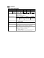
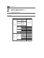
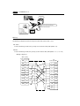
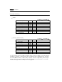
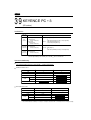
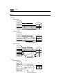
Sharp PC ....................................................................................................................................... 2-1
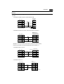
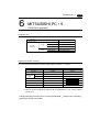
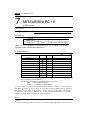
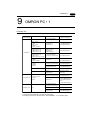
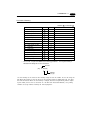
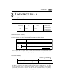
MITSUBISHI PC • 1 ..................................................................................................................... 2-8
MITSUBISHI PC • 2 ................................................................................................................... 2-14
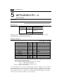
MITSUBISHI PC • 3 ................................................................................................................... 2-18
MITSUBISHI PC • 4 ....................................................................................................................... 2-20
MITSUBISHI PC • 5 ....................................................................................................................... 2-23
MITSUBISHI PC • 6 ....................................................................................................................... 2-26
MITSUBISHI PC • 7 ....................................................................................................................... 2-27
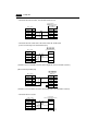
OMRON PC • 1 .............................................................................................................................. 2-29
OMRON PC • 2 .............................................................................................................................. 2-34
HITACHI PC • 1 ............................................................................................................................. 2-35
HITACHI PC • 2 ............................................................................................................................. 2-38
Matsushita PC ............................................................................................................................... 2-41
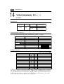
YOKOGAWA PC • 1 ....................................................................................................................... 2-44
15.
16.
17.
18.
19.
20.
21.
22.
23.
24.
25.
26.
27.
28.
29.
30.
31.
32.
33.
34.
35.
36.
37.
38.
39.
40.
41.
42.
43.
44.
45.
46
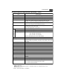
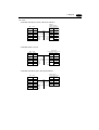
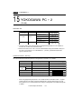
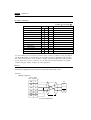
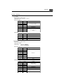
YOKOGAWA PC • 2 ....................................................................................................................... 2-46
YASKAWA PC • 1 .......................................................................................................................... 2-49
YASKAWA PC • 2 .......................................................................................................................... 2-52
TOYOPUC PC ............................................................................................................................... 2-54
FUJI PC • 1 .................................................................................................................................... 2-57
FUJI PC • 2 .................................................................................................................................... 2-60
FUJI PC • 3 .................................................................................................................................... 2-63
FUJI PC • 4 .................................................................................................................................... 2-65
Koyo PC ......................................................................................................................................... 2-67
Allen-Bradley PC • 1 ...................................................................................................................... 2-72
Allen-Bradley PC • 2 ...................................................................................................................... 2-77
GE Fanuc PC • 1 ........................................................................................................................... 2-81
GE Fanuc PC • 2 ........................................................................................................................... 2-83
TOSHIBA PC ................................................................................................................................. 2-85
TOSHIBA MACHINE PC ................................................................................................................ 2-87
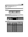
SIEMENS PC • 1 ........................................................................................................................... 2-89
SIEMENS PC • 2 ........................................................................................................................... 2-91
SIEMENS PC • 3 ........................................................................................................................... 2-93
SIEMENS PC • 4 ........................................................................................................................... 2-95
SIEMENS PC • 5 ........................................................................................................................... 2-97
Shinko PC ...................................................................................................................................... 2-99
SAMSUNG PC ............................................................................................................................. 2-101
KEYENCE PC • 1 ........................................................................................................................ 2-103
KEYENCE PC • 2 ........................................................................................................................ 2-105
KEYENCE PC • 3 ........................................................................................................................ 2-108
LG PC .......................................................................................................................................... 2-110
FANUC PC ................................................................................................................................... 2-113
FATEK AUTMATION PC .............................................................................................................. 2-115
IDEC PC ...................................................................................................................................... 2-117
MODICON PC ............................................................................................................................. 2-119
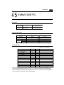
YAMATAKE PC ............................................................................................................................ 2-121
TAIAN PC .................................................................................................................................... 2-123
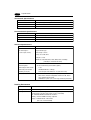
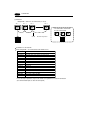
Hardware
Specifications
1. Special Features
2. Notes on Usage
3. System Composition
4. Names of Components
5. Dimensions and Panel Cut-out
6. Mounting Procedure
7. Wiring
8. Specifications
9. Serial Connector (CN1)
10. Setting of Dip Switches
11. Modular Jack 1 & 2
12. Bar Code Reader Interface
13. Printer Interface (CN2)
14. Video Interface
15. Connection
16. Operation of ZM-** Main Menu
17. Function Switches
18. Terminal Converter (ZM-1TC)
19. Expansion I/O module (ZM-322M)
20. Card Recorder (ZM-1REC)
21. Cable for transporting the panel (ZM-80C)
22. Printer Cable (ZM-80PC)
23. 2Port Adapter (ZM-1MD2)
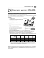
24. Expansion Memory (ZM-4EM)
25. Expansion Memory (ZM-43EM)
26. Expansion Memory (ZM-43SM/80SM)
1 Special Features
1
1-1
Special Features
The Control Terminal ZM-42/43/52/72/82 series are programmable indication equipment and support tool that
use LCD display and touch panel functions.
They communicate by the programmable controller (thereafter PC) and programless, and you can display a
variety of functions as well as inputting data by the touch panel to already programmed panel data.
You can select the size of panel such as 5.7 inch display, 7.7 inch display, 10.4 inch display and 12.1 inch
display, according to your needs.
Some special features include: free position of the switch, 128-color display, new functions for better quality in
representation and manipulation including a new debug function realized by the exclusive simulation software.
They also are subject to adapt to a variety of needs, and such special features are realized by putting support
tool such as expansion I/O or the memory card reader.
1) 128-color Display
128-color display which makes colorful expression possible is realized. Not only drawings but also bitmap
files are clearly displayed. (ZM-52/72/82)
2) Data Sheet Printing Function
It is possible to make the original data sheet screen by the panel editor (= the editing software).
Daily reports or monthly reports that the operator must fill out can be printed in an instant.
3) Sampling Function
It is possible to carry out battery back up of the history data by the expansion memory(ZM-43SM/80SM).
4) Macro Function
With this function, ZM-42/43/52/72/82 series can make programs which previously had to be produced by
PC.
5) Multi Window Function
Up to three windows can be displayed simultaneously on a screen.
It is easy to move or delete the displayed windows.
6) Video Function
ZM-** series can be connected to a video or a CCD camera, and the image which is taken by a video or a
camera can be displayed directly in a screen of ZM-** series
7) Correspondense to Ethernet, FL-net
It is connectable with Ethernet and FL-net if an Ethernt module ZM-80NU is mounted.(ZM-43/52/72/82)
- Ethernet
The high-speed response is realized by the N:N programless connection betwen ZM-43/52/72/82 and
PC(*). The communication with a server and between ZM-43/52/72/82s is also possible without a
server.Moreover, screen data transmission is also possible at easy and high speed through a server.
(*Connection is restricted to Ethernet correspondence PC.)
- FL-net
It connects with FL-net to which introduction is progressing as an open field network, and high-speed
communication is possible in each controller and a masterless token system.
8) Expansion memory
Extension of screen data has ZM-4EM(for ZM-52/72/82) and ZM-43EM(for ZM-43), ZM-80SM(for ZM-52/
72/82) and ZM-43EM(for ZM-43) for backup of an internal memory.
9) Ladder monitor ability is carried
A ladder figure display of one network is possible. It is utilizable for shortening of troubleshooting and a
down time. (Refer to ZM-42/52/72/82 User’s Manual Ladder Monitor version.)
10) Character expression and a Gothic font
The Gothic font of 16 sizes can be chosen to 8 to 72 points. Moreover, since it can be used for numerical
data, an unusual display, etc., power of expression can be improved.
- The combined use with a present 16/32 dot font is impossible. An expansion memory may be needed.
- The screen edit software ZM-71SE correspondence to the version V1.2.0.0.
- For the names of ZM-42/43/52/72/82 series, please refer to “3. System Composition” chapter.
1-2
2
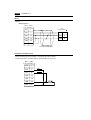
1 Notes on Usage
Notes on Usage
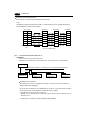
Environmental Limits
1. Use Control Terminal at an ambient temperature
of 0 to 50ºC, and a relative humidity of 35 to 85
%RH. (But, a ZM-72D/T STN multi-color display
can be used at 0 to 40ºC.)
5. Never install Control Terminal in a place where
impacts or vibrations may be transmitted.
0∼50℃
50
40
30
20
10
0
2. Install a forced fan or an air conditioner to
maintain the ambient temperature when it is
higher than the above mentioned range.
6. Avoid any place in which there is the possibility
that water, corrosive gas, flammable gas,
solvents or coolants, grinding oil can come in
contact with the unit. Never install the unit in a
place where dust, salt and metallic particles are
present.
Fan
YOUZAI
Vent
Locations
3. Avoid places where moisture may easily
condense due to sudden temperature changes.
1. Secure sufficient space around Control Terminal
for ventilation.
4. Avoid direct sunlight.
2. Never attach Control Terminal to the top of any
apparatus generating high levels of heat (heater,
transformer, large-capacity resistor, etc.).
1 Notes on Usage
3. Never install Control Terminal in the same
compartment as high-voltage equipment. The
unit should be at least 200 mm away from highvoltage lines or power cables.
1-3
4. Securely fasten and lock every connector for
each cable. Double-check this before turning the
power on.
k!
Loc
5. In a dry environment, Control Terminal may
generate a large amount of static electricity.
Therefore, before touching the unit, touch a
grounded metallic section to discharge the static
electricity.
Usage
1. An emergency stop circuit must be composed of
an external relay circuit with a start signal for
Control Terminal built in. Do not create switches
on Control Terminal to be used in case of
emergency.
Alcohol
BENZINE
Switch to be used
in emergency
Emergency
Stop
2. Control Terminal has a glass screen. Never drop
or subject the unit to strong impacts.
3. Tighten mounting screws with the following
torques.
Screw
Screw Size
Torque (N • m)
ZM-42/43/52
M3
0.29~0.49
ZM-72/82
M4
0.49~0.69
Type
Note :Never fasten these screws too tightly,
otherwise the cover of Control Terminal may be
deformed.
6. Application of thinner may discolor Control
Terminal. Use alcohol or benzine available
commercially for cleaning.
7. Never remove any printed circuit board from
Control Terminal. (This will harm the unit.)
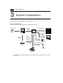
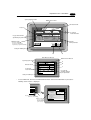
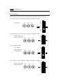
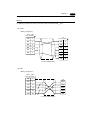
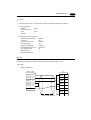
1 System Composition
1-4
3
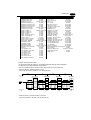
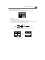
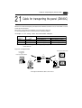
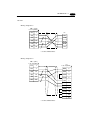
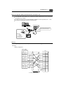
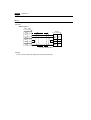
System Composition
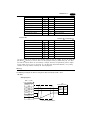
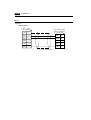
System Composition / Model Indication / Peripheral Equipment
System Composition
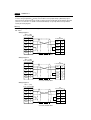
The following illustration shows possible system configurations using ZM-**.
Screen edit software
for ZM series
During operation
(Link communication)
Transferring
screen data
Creating screens
RS-232C/RS-422
ZM-80C
ZM-71SE
Personal Computer
Transferring
screen data
ZM-80C
ZM-**
Transferring
screen data
or
Memory manager
/Data logging
During operation
(General serial
communication)
Link module
RS-232C/RS-422
Exclusive cable
General-purpose
computer
ZM-1REC Cable
Video / CCD camera *
Card Recorder
Printer Cable
ZM-80PC
Bar code reader
connecting cable ZM-80BC
ZM-1REC
Bar code reader
Printer
* The models that possess the video input interface function are ZM-72TV/TVC/TSV/TSVC and ZM82TV/TVC.
1 System Composition
1-5
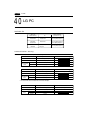
Control Terminal
Classification
ZM-42 series
ZM-43 series
ZM-52 series
ZM-72 series
ZM-82 series
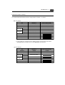
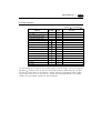
Model Name
Specifications
ZM-42D
5.7 inches STN color, 320 × 240 dots
ZM-42L
5.7 inches STN monochrome, 320 × 240 dots
ZM-43T
5.7 inches TFT monochrome, 320 × 240 dots
ZM-43D
5.7 inches STN color, 320 × 240 dots
ZM-43L
5.7 inches STN monochrome, 320 × 240 dots
ZM-52D
7.7 inches STN color, 640 × 480 dots
ZM-72T
10.4 inches TFT color, 640 × 480 dots
ZM-72TC
10.4 inches TFT color, 640 × 480 dots, memory card I/F included
ZM-72TV
10.4 inches TFT color, 640 × 480 dots, video Input included
ZM-72TVC
10.4 inches TFT color, 640 × 480 dots, video Input + memory card I/F included
ZM-72TS
10.4 inches TFT color, 800 × 600 dots
ZM-72TSC
10.4 inches TFT color, 800 × 600 dots, memory card I/F included
ZM-72TSV
10.4 inches TFT color, 800 × 600 dots, video input included
ZM-72TSVC
10.4 inches TFT color, 800 × 600 dots, video input + memory card I/F included
ZM-72D
10.4 inches STN color, 640 × 480 dots
ZM-72DC
10.4 inches STN color, 640 × 480 dots, memory card I/F included
ZM-82T
12.1 inches TFT color, 800 × 600 dots
ZM-82TC
12.1 inches TFT color, 800 × 600 dots, memory card I/F included
ZM-82TV
12.1 inches TFT color, 800 × 600 dots, video input included
ZM-82TVC
12.1 inches TFT color, 800 × 600 dots, video input + memory card I/F included
ZM-82DC
12.1 inches STN color, 800 × 600 dots, memory card I/F included
1-6
1 System Composition
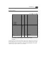
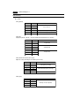
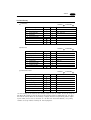
Support tools
The following options are available for useing ZM-** series more effectively
Item
Model
Specifications
Applicable models
ZM-82 ZM-72 ZM-52 ZM-43 ZM-42
Network
module
UDP / IP protocol is supported in the
module for connecting ZM-** to Ethernet.
Moreover, as FL-net, it correspondences
ZW-80NU to FA link protocol and cyclic transmission
and message transmission (Word read/
write) are supported.
ZM-4EM
Expansion
memory
Extension print circuit board to extend
the memory for display data back-up.
The capacity is 4 bytes for FPROM.
Memory capacity is 4 M bytes of flash
ZM-43EM memory, and is used for extension of a
screen data storage capacity.
Memory capacity is 512 K bytes of SRAM
memory, and is used for sampling data
and backup of an internal memory, and
ZM-80SM a calendar setup.
ZM-43SM
Terminal
converter
ZM-1TC
Used for connection between a ZM-**
and a PC at the RS-422/485 terminal
block.
Expansion
I/O module
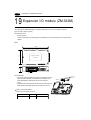
ZM-322M
Used as an external I/O module for PC.
It has 16 inputs and 16 outputs.
Card
recorder
ZM-1REC
Reads display data created by personal
computer, on works as am external
memory storage system for the
memory manager and data logging
functions.
Dual port
interface
ZM-1MD2
Add-on connector with two ports,
specifically designed for the connector
on the MITSUBISHI’s A/Q CPU
programmer.
Data transfer
cable
ZM-80C
Connects ZM-** to a personal
computer, on a personal computer to
ZM-1REC to a printer.
Printer cable
ZM-80PC
Connect ZM-** to a printer.
Barcode reader
connection
ZM-80BC
cable
Connect ZM-** to a barcode reader.
In case it connects multi-link 2, it is used
Cable for
Multi-link2
ZM-80MC for connecting between ZM-** master
master station
station and ZM-** slave station.
Protect sheet
Screen edit
software
ZM-42GS
ZM-52GS
ZM-72GS
ZM-82GS
It is the sheet which protects an
operation panel side.
ZM-71S
Japanese
ZM-71SE
English
Application software for
editing display data.
1 System Composition
1-7
ZM-71S, ZM-71SE
Application software for editing display data.
• ZM-71S : For Windows95/98/NT4.0 (Japanese)
• ZM-71SE : For Windows95/98/NT4.0 (English)
ZM-80C (Data Transfer Cable)
Connects ZM-** to a personal computer, or a personal computer to ZM1REC.
ZM-80PC (Printer Cable)
Connects ZM-** to a printer.
O
M
0
ZM-4EM, ZM-43EM (Expansion Memory)
1
P
V
9
J
7
-M
E
M
C
P
F
0
R
2
O
0
0
M
4
1
C
N
1
F
R
· ZM-4EM : For ZM-52/72/82
· ZM-43EM : For ZM-43
Extension print circuit board to extend the memory for display data back-up.
There is 4Mbyte type (ZM-4EM,ZM-43EM) for FPROM.
M n O 2-
JAP
AN
SANYO
Li
CR2430
TS
N
C
P
0
2
1
V 7
6 2-M 2
C
B
1
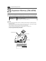
ZM-43SM, ZM-80SM (Expansion Memory)
CELL
3 VO
L
· ZM-43SM : For ZM-43
· ZM-80SM : For ZM-52/72/82
Extension print circuit board to back-up the memory for sampling data, ZM-**
Internal Memory and Memo Pad. There is SRAM 512K byte type. It is also
possible to set the calendar for displaying in ZM-** at this cassette.
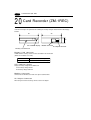
ZM-1REC (Card Recorder)
Reads display data created by personal computer, or works as an external
memory storage system for the memory manager and data logging functions.
CN
1
SW
TB
1
ZM-1TC (Terminal Converter)
1
Used for connection between a ZM-** and a PC at the RS-422/485 terminal
block.
1 System Composition
1-8
G
P
P
ZM-1MD2 (ACPU/QCPU Dual Port Interface)
Add-on connector with two ports, specifically designed for the connector on
the MITSUBISHI's ACPU/QCPU programmer. This can improve operability of
the ACPU/QCPU programmer that is directly connected.
GD
ZM-80NU (Network Module)
It is a module for making it correspondence to the network of Ethernet and FLnet. It is possible to connect more than one sets of ZM-**s to one set of PC. In
the same network, other equipments can be connected and it contributes to a
price down of the whole system greatly.
ZM-322M (Expansion I/O module)
Used as an external I/O module for PC. It has 16 inputs and 16 outputs.
REC-MCARD (Memory Card)
H
C
U
O
IT
N
O
M
発
紘
電
機
株
式
会
F
56
C2
RE 社
Used as a recording medium for display data back-up and for the memory
manager or data logging function.
SRAM / FLASH ROM
Card Type : JEIDA Ver.4.0 or later
ZM-80BC (Cable for Bar Code Reader) 2m
Connects ZM-** to a bar code reader.
ZM-80MC (Cable for Multi-Link 2 master station) 3m
A cable which is used for connecting the ZM-** master station and the ZM-**
slave station in the Multi-Link 2 connection.
ZM-42GS/52GS/72GS/82G (Protection Sheet)
· ZM-42GS : For ZM-42/43
· ZM-52GS : For ZM-52
· ZM-72GS : For ZM-72
· ZM-82GS : For ZM-82
Protects the operation panel surface. Five sheets are included in one
package.
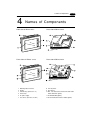
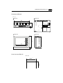
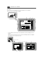
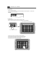
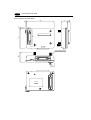
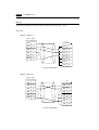
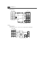
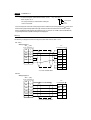
1 Names of Components
4
1-9
Names of Components
Front side of ZM-42 series
Rear side of ZM-42 series
CN2
Front side of ZM-43 series
MJ2
CN1
(+)
DC24V
(−)
MJ1
Rear side of ZM-43 series
24VDC
MJ2
CN2
1.
2.
3.
4.
5.
7.
Mounting holes for fixtures
Display
Function keys (Refer to P1-51.)
Power lamp
DC power supply
CN1: for PC (RS-232C, RS-422)
MJ1
CN1
8. CN2: for printer
9. Dip switches
10. MJ1, 2: for data transfer and for bar-code reader
and for ZM-1REC (option)
11. for ZM-2EM/4EM (option)
13. for Communication interface module (option)
1 - 10
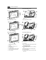
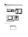
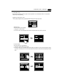
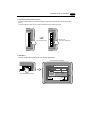
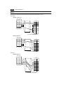
1 Names of Components
Front side of ZM-52 series
Rear side of ZM-52 series
(+)
DC24V
(−)
MJ1
CN1
MJ2
CN2
Front side of ZM-72 series
Rear side of ZM-72 series
L
100240VAC
N
CN1
NC
MJ2
MJ1
CN2
Front side of ZM-82 series
Rear side of ZM-82 series
L
100240VAC
N
CN1
NC
MJ2
MJ1
CN2
1.
2.
3.
4.
5.
6.
7.
8.
Mounting holes for fixtures
Display
Function keys (Refer to P1-51.)
Power lamp
DC power supply
AC power supply / DC power supply
CN1: for PC (RS-232C, RS-422)
CN2: for printer
9. Dip switches
10. MJ1, 2: for data transfer and for bar-code reader
and for ZM-1REC (option)
11. for ZM-2EM/4EM (option)
12. for video (ZM-72TV/TVC/TSV/TSVC, ZM-82TV/
TVC)
13. for Communication Interface module (option)
14. for ZM-322M (option)
15. Card interface (ZM-72TC/TVC/TSC/TSVC, ZM82TC/TVC)
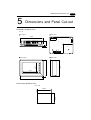
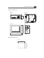
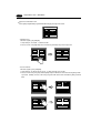
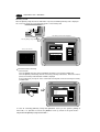
1 Dimensions and Panel Cut-out
5
1 - 11
Dimensions and Panel Cut-out
Dimensions of ZM-42 series
Unit : mm
Rear View
Top View
5
45
173.6
CN1
CN2
MJ2
Front View
MJ1
Side View
SYS
117.2
F2
F3
130.8
138.8
88.4
F1
F4
F5
182.5
Panel cut-out of ZM-42 series
Unit : mm
+0.5
-0
131 +0.5
-0
174
1 - 12
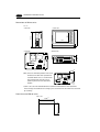
1 Dimensions and Panel Cut-out
Dimensions of ZM-43 series
Unit:mm
○Front view
○Side view
SYS
F2
F3
POWER
138.8
130.8
86.4
F1
F4
115.2
F5
182.5
○Bottom view
6
○Rear view
+
24VDC
4
47.3
−
ご使用時以外は剥がさないでください
Do not remove this seal.
unless the optional unit is mounted.
MJ2
MJ1
CN1
CN2
60mm※
(Note) Since the connection positions of the serial
connector CN1 differ when replaced and
used from ZM-42 series, it is inconvenient
with an attachment space. Be sure to
perform a prior check of an attachment
position.
+
24VDC
−
ご使用時以外は剥がさないでください
Do not remove this seal.
unless the optional unit is mounted.
MJ2
CN2
MJ1
CN1
*60mm is not a size with consideration to the attachment and detachment after attachment.
Since it changes in the difference in a wiring system, the electric wire size which wires that check
by real wiring
Panel Cut-out of ZM-43 series
Unit : mm
+0.5
−0
+0.5
−0
131
174
1 Dimensions and Panel Cut-out
1 - 13
Dimensions of ZM-52D
Unit : mm
Top View
Rear View
220
TB1
(+)
DC 24V
60.1
( )
CN1
6
MJ2
CN2
Front View
Side View
SYS
F1
F4
165
F3
175
121
F2
F5
160
F6
F7
230
Panel Cut-out of ZM-52D
Unit : mm
+0.5
-0
+0.5
-0
165.5
220.5
MJ1
1 - 14
1 Dimensions and Panel Cut-out
Dimensions of ZM-72 series
Unit : mm
Rear View
Top View
288
L
100240VAC
N
CN1
16
76.3
NC
MJ2
CN2
Front View
Side View
SYS
F1
F3
F4
215.2
240
158
F2
F5
211
F6
F7
310
Panel Cut-out of ZM-72 series
Unit : mm
+0.5
-0
+0.5
-0
216.2
289
MJ1
1 Dimensions and Panel Cut-out
Dimensions of ZM-82 series
Unit : mm
Top View
Rear View
312
L
100240VAC
NC
CN1
16
79.8
N
MJ2
CN2
Side View
245.2
270
185
Front View
247
SYS
F1
F2
F3
F4
F5
F6
F7
334
Panel Cut-out of ZM-82 series
Unit : mm
+0.5
-0
+0.5
-0
246.2
313
MJ1
1 - 15
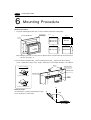
1 Mounting Procedure
1 - 16
6
Mounting Procedure
Mounting Procedure
1. Cut out the mounting panel (Max. thick: 3.2 mm) to match the dimensions shown below.
Mounting panel
(In case of ZM-52D)
Unit : mm
174
220.5
+0.5
-0
+0.5
-0
Cut-out
289
F1
165.5
+0.5
-0
ZM-52D
131
ZM-42 Series
ZM-43 Series
SYS
+0.5
-0
+0.5
-0
220.5
+0.5
-0
313
+0.5
-0
165.5 -+0.5
0
F2
F3
ZM-72 Series
F7
ZM-82 Series
246.2
F6
216.2
F5
+0.5
-0
+0.5
-0
F4
(Note) Although a panel cut size is the same, the positions of the serial connector CN1 on the back face is
not same. See page 1-12.
2. Insert the fixtures attached to ZM-** into the mounting holes on ZM-**. Tighten them with the locking
screws. - Number of the fixtures: 4 pcs. -Torque : ZM-42/43/52 0.29~0.49N·m, ZM-72/82 0.49~0.686N·m
Fixture
Mounting panel
Dimensions of Fixtures
(Unit : mm)
Mounting hole
10.5
20
.0
Mounting hole
17.8
for ZM-42/43 Series/ZM-52D
ZM-**
TB1
(+)
DC 24V
(-)
MJ2
MJ1
10.5
30
.0
17.8
for ZM-72 Series/ZM-82 Series
90˚
Mounting Angle
135˚
is
pl
ay
135˚
D
The module (ZM-**) shall be installed within the angle
of 0 to 135 degrees as shown below.
Display
0˚
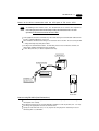
1 Wiring
7
1 - 17
Wiring
Electrical Wiring
Connects the cable for power supply to TB1 on the rear side of ZM-**.
DC24V
MJ2
TB1
(+)
(-)
MJ1
Power supply
DC24V±10%
CN1
(+)
DC 24V
(-)
CN2
Earth
ZM-42/43 Series, ZM-52D
Type : AC100-200V
L
100240VAC
N
NC
TB1
L
CN1
Power supply
100-200VAC
N
MJ2
NC
MJ1
CN2
Earth
ZM-72 Series/ZM-82 Series
Type
Screw Screw Size Torque (N • m)
Clamp Terminal (Unit : mm)
ZM-42/43 Series, ZM-52D
M3.5
0.49
7.0MAX
7.0MAX
ZM-72 Series/ZM-82 Series
M3.5
0.49
8.0MAX
8.0MAX
When TB1 is used for wiring, refer to the value as described above table.
The power source used must be within the allowable voltage fluctuation.
Use a power source with low noise between the cables or ground and the cable.
Use as thick a power cable as possible to minimize any drop in voltage.
Keep cables of 100V AC and 24V DC sufficiently away from high-voltage, large-current cables.
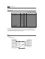
Notes on Usage of ZM-72 series/ZM-82 series (100 to 240 VAC specifications)
Generally, an isolating transformer improves noise resistance. However, if the display unit is far away
from the secondary port of the transformer and noise gets mixed in, an isolating transformer becomes
unnecessary.
If any power voltage fluctuation caused by noise is expected, it is recommended that a voltage stabilizer
be used.
Power Supply
Insulation transformer
or
Stabilized transformer
to ZM-72 Series/
ZM-82 Series
1.25mm2 twisted
1 - 18
1 Wiring
Grounding
This equipment must be earthed.
ZM-**
An independent earth pole shall be used for Control Terminal.
(Earth construction is the class-3 grounding. The level of
grounding resistance should be less than 100 Ω.)
Use a cable which has a nominal cross section of more than
2mm2 for grounding.
Grounding point shall be near the Control Terminal to shorten
the distance of grounding wires.
When the unit is grounded along with other machines, or is
grounded to a part of a building, it can be adversely affected.
If any input-output errors occur due to the grounding, detach the
FG terminal from the ground.
Other
equipment
Class-3 grounding
Wiring for communication
Never place the communication cable
with electric circuits.
Never bundle these cables together with
other wires in ducts or electric boxes
using cord locks. Although it is tempting
to bundle all the cables neatly together,
this does not necessarily lead to a noiseresistant configuration.
It is recommended that the communication cable be independently wired.
Wiring duct
Communication cable
Communication cable
Power cable and control cable
Power cable and control cable
Cord lock
1 Specifications
8
1 - 19
Specifications
General Specifications
Type
Item
ZM-43 series
ZM-42 series
24V DC
Rated Voltage
24VDC 10%
Permissible Range
Power Supply
ZM-52D
of Voltage
10ms or less
Permissible Momentary Power Failure
Demand
10W or less
20W or less
17A
1ms
5A
1.5ms
Rushed Electric Current
With-stand voltage
500V DC, 10M
Physical Environment
Insulation Resistance
Ambient Temperature
Storage Ambient Temperature
Mechanical
Working
Conditions
Electrical
Working
Conditions
~+50
~+60
No conductive dust
Dust
No cutting oil or no organic solvent to cling to the unit
Solvent Resistance
No corrosive gas
Corrosive Gas
Vibration frequency: 10~150Hz, Acceleration: 9.8m/s 2 (1.0G)
3 directions of X, Y and Z: one hour
Pulse shape: Sine half wave,
Shock Resistance
Peak acceleration: 147m/s2 (15G), 3 directions of X, Y and Z: six times
Noise voltage: 1500Vp-p, noise width: 1 s
Noise Resistance
Front panel: 6kV
Static Electricity Discharge Resistance
Class-3 grounding
Grounding
Mounting Conditions
0
-10
85% RH or less (without dew condensation)
Ambient Humidity
Vibration Resistance
or more
Structure
Protection structure: front panel complies with IP65 (when using gasket)
rear panel complies with IP20
Form: in a body
Mounting procedure: inserted in a mounting panel
Cooling naturally
Cooling System
Weight
Dimensions W X H X D (mm)
Panel Cut-out (mm)
Case Color
Material
Approx. 0.8kg
182.5 X 138.8 X 50
174
+0.5
-0
+0.5
X 131 -0
Approx. 0.8kg
Approx. 1.1kg
*2
182.5 X138.8 X 57.3
+0.5
174 +0.5
-0 X 131 -0
230 X 175 X 66.1
+0.5
GREY
BLACK*3
GREY
PC/ABS
PC/PS
PC/ABS
*1 For only the specifications of AC power supply
*2 including 4mm, the size of boss for communication module
+0.5
220.5-0 X 165.5 -0
1 Specifications
1 - 20
Type
Power Supply
Item
Rated Voltage
100 to 240V AC
100 to 240V AC
Permissible Range
85 to 265 VAC
85 to 265 VAC
(47 to 440 Hz)
(47 to 440 Hz)
Permissible Momentary Power Failure
20ms or less
20ms or less
Demand
45 VA or less
50 VA or less
Rushed Electric Current
20A: 100 VAC
30A: 200 VAC
20A: 100 VAC
30A: 200 VAC
of Voltage
With-stand voltage
Between AC external terminals and FG: 1500V AC per min.
500V DC, 10M or more
Physical Environment
Insulation Resistance
Mechanical
Working
Conditions
ZM-82 series
ZM-72 series
0
Ambient Temperature
~+50
-10
Storage Ambient Temperature
)
~+60
No conductive dust
Dust
No cutting oil or no organic solvent to cling to the unit
No corrosive gas
Corrosive Gas
Vibration Resistance
~+40
85% RH or less (without dew condensation)
Ambient Humidity
Solvent Resistance
(ZM-72D/DC: 0
Vibration frequency: 10~150Hz, Acceleration: 9.8m/s 2 (1.0G)
3 directions of X, Y and Z: one hour
Pulse shape: Sine half wave,
Shock Resistance
Electrical
Working
Conditions
Peak acceleration: 147m/s2 (15G), 3 directions of X, Y and Z: six times
Noise voltage: 1500Vp-p, noise width: 1 s
Noise Resistance
Front panel: 6kV
Static Electricity Discharge Resistance
Class-3 grounding
Mounting Conditions
Grounding
Structure
Protection structure: front panel complies with IP65 (when using gasket)
rear panel complies with IP20
Form: in a body
Mounting procedure: inserted in a mounting panel
Cooling naturally
Cooling System
Weight
Approx. 2.5kg
Approx. 3.0kg
Dimensions W X H X D (mm)
310 X 240 X 92.3
334 X 270 X 95.8
Panel Cut-out (mm)
289 -0 X 216.2 -0
Case Color
Material
+0.5
+0.5
+0.5
313 +0.5
-0 X 246.2 -0
GREY
PC/ABS
1 Specifications
1 - 21
Display Specifications
Item
Type
ZM-42L
ZM-42D
ZM-43D
ZM-43L
ZM-43T
ZM-52D
STN moSTN moDisplay Device
nochrome STN color nochrome STN color TFT color STN color
LCD
LCD
LCD
LCD
LCD
LCD
320 × 240
640 × 480
Resolution W × H (dots)
Dot Pitch W × H (mm)
0.36 × 0.36 0.12 × 0.36 0.36 × 0.36 0.12 × 0.36 0.36 × 0.36 0.082 × 0.246
W × H (mm)
Color
(5.7 inches)
(7.7 inches)
Monochrome
Monochrome
16 colors
8 gradation
8 gradation
+ blinking
+ blinking
+ blinking
128 colors
+ blinking
16 colors
16 colors
+ blinking
Cold cathode rectifier
Back-light
Contrast Adjustment
Back-light Average Life *
Power Lamp
Item
157.4 × 118.1
115.2 × 86.4
Effective Display Area
By function switches (only in case of STN color type)
Approx.
Approx. 25,000H
Approx. 50,000H
25,000H
The lamp is lit when the power is supplied.
Type ZM-72D series ZM-72T series ZM-72TS series
Display Device
Resolution W × H (dots)
Dot Pitch W × H (mm)
STN color
LCD
TFT color
LCD
640 × 480
0.11 × 0.33
ZM-82T series
TFT color
LCD
800 × 600
0.33 × 0.33
0.264 × 0.264
0.3075 × 0.3075
Effective Display Area
211.2 × 158.4
246.0 × 184.5
W × H (mm)
(10.4 inches)
(12.1 inches)
Color
128 colors
+ blinking 16 colors
Cold cathode rectifier
Back-light
Contrast Adjustment
By function switches (only in case of STN color type)
Back-light Average Life * Approx. 10,000H
Power Lamp
Approx. 25,000H
The lamp is lit when the power is supplied.
* When the normal temperature is 25˚C, and the surface illuminance of the display is 50% of the default.
1 - 22
1 Specifications
Display Function Specifications
Item
Display Language
Characters
Specifications
Japanese
Eng./W. Europe
1/4-size, 1-byte
ANK code
2-byte (16-dot) JIS 1st and 2nd
2-byte (32-dot)
JIS 1st
Size of Characters
Number of Characters
ASCII code
ASCII code
ASCII code
Chinese
Chinese (simplified)
Korean
ASCII code
ASCII code
ASCII code
Chinese Chinese (simplified) Hangul (without Kanji)
1/4-size : 8 ¥ 8 dots
1-byte : 8 ¥ 16 dots
2-byte : 16 ¥ 16 dots or 32 ¥ 32 dots
Enlarge : W, 1 to 8 H, 1 to 8
Resolution
1/4-size
1-byte
2-byte
320 ¥ 240
640 ¥ 480
800 ¥ 600
40 columns ¥ 30 lines
40 columns ¥ 15 lines
20 columns ¥ 15 lines
80 columns ¥ 60 lines
80 columns ¥ 30 lines
40 columns ¥ 30 lines
100 columns ¥ 75 lines
100 columns ¥ 37 lines
50 columns ¥ 37 lines
Property of Characters
Display property : normal, reverse, blinking, bold, shadow
Color : 128 colors + blinking 16 colors /16 colors+ blinking /monochrome 8
graduation+blinking
Foreign characters
registration
Only the Japanese characters are possible to set
Full size 16 ¥ 16 dot, 63
when the use of 32 dot font is possible: Full size 32 ¥ 32 dot, 63
Kind of Drawing
Lines : line, continuous lines, box, parallelogram, polygon
Circles : circle, arc, sector, ellipse, elliptical arc, elliptical sector
Others : tile patterns
Property of Drawing
Type of lines : 6 types (fine, thick, dot, chain, broken, two-dot chain)
Tile patterns : 16 types (incl. user-definable 8 types)
Display property : normal, reverse, blinking
Color : 128 colors + blinking 16 colors /16 colors+ blinking /monochrome 8
graduation+blinking
Color specification : foreground, background, boundaries (line)
1 Specifications
1 - 23
Function Performance Specifications (All the ZM-** series)
Specifications
Item
Screens
Max. 1024
Screen Memory
FP-ROM (flash ROM), Appox. 2,816K bytes*1(different from the language)
Switches
768 per screen (192 per screen for ZM-42/43 Series)
Switch operation mode
Set, reset, momentary, alternate, to light
(possible to press a function switch and a display switch at the same time)
[Matrix type : 2 switches on the display can be pressed at the same time]
Lamps
Reverse, blinking, exchange of graphics
768 per screen (192 per screen for ZM-42/43 Series)
Data Setting
Graphs
Pie, bar, panel meter and closed area graph can be displayed without limit.
Total capacity per screen: within 128KB
Statics and trend graphs: Max. 256 per layer*2
Numerical Data Display
No limits, total capacity per screen: within 128 KB
Character Display
No limits, total capacity per screen: within 128 KB
Message Display
Resolution : 320 × 240, Max. 40 characters
640 × 480, Max. 80 characters
800 × 600, Max. 100 characters
No limits, total capacity per screen: within 128 KB
Messages
6144 lines
Sampling
Sampling display of buffer data
(constant sample, bit synchronize, bit sample, relay sample, alarm function)
Multi-Overlaps
Max. 1024
Data Blocks
Max. 1024
Graphic Libraries
Max. 2560
Patterns
Max. 256
Macro Blocks
Max. 1024
Page Blocks
Max. 1024
Direct Blocks
Max. 1024
Screen Blocks
Max. 1024
Temperature Control Network Table Max. 32
Calendar
Provided
Hard-Copy
Provided
Buzzer
Provided, 2 types (intermittent short and long sounds)
Self-diagnostic Function
Self-test function of switches
Check function of communication parameter setting
Check function of communication
*1 If the hardware version is the following version, or ZM42/43 is used, the screen memory is
approx. 760K bytes.
ZM82T Series : A~E, ZM-72TS Series : A~E, ZM-72T Series : A~F, ZM-72D Series : A~E,
ZM-52D Series : A~C
*2 Layer : 4 per screen (base + 3 overlaps)
1 - 24
1 Specifications
Touch Panel Specifications
Item
Specifications
Switch Resolution
Analog, 1024(W) ¥ 1024(H)
Form
Resistance film form
Life of Touch Panel
Use of one million times or more
Function Switch Specifications
Item
Specifications
Number of Switches
8 (6 for ZM-42/43)
Type of Switch
Pressure sensitive switches
Life of Switch
Use of one million times or more
Interface Specifications
Item
Specifications
Serial Interface
RS-232C, RS-422/485
for connecting PC
Asynchronous type
(D-sub 25 pins, female)
Data length: 7, 8 bits
Parity: even, odd, none
Stop bit: 1, 2 bits
Baud rate: 2400, 4800, 9600, 19200, 38400, 57600, 115200bps
(115200bps is invalid for ZM-42/43)
Serial Interface 1 and 2 for
RS-232C, RS-422/485
transferring data
* In case of connecting card recorder (option) :
/connecting bar-code reader
1 slot
/connecting card recorder *
SRAM/FROM: Max. 16M byte
(modular jack, 8 pins)
Printer Interface
which complies with JEIDA Ver. 4.0 (with some limits)
Complies with centronics, half pitch 36 pins (for PC98)
NEC: PR201, EPSON: compatibles with ESC/P-J84, ESC/P
super function, ESC/P24-J84
CBM292/293 printer (The screen copy cannot be printed out.)
Drawing Environment
Item
Specifications
Drawing Method
Exclusive drawing software
Drawing Tool
Name of exclusive drawing software : ZM-71S (Japanese), ZM-71SE (English)
Personal computer : with i486 or more (Pentium or more is recommended)
OS : Microsoft Windows 95/98 or NT version 4.0
Memory : minimum 40MB of memory to operate
Display : resolution of 640 · 480 or more
(800 · 600 is recommended)
1 Specifications
1 - 25
Compatible PC for connection
Maker
Sharp
PC Model
J-board, JW10, JW20/20H, JW30H
W70H/100H, JW50/70/100, JW50H/70H/100H
MITSUBISHI
A Series/Q Series link module/CPU port,
FX1/2 Series
OMRON
C Series, COM Series, CV Series
HITACHI
HIDEC H300/700/2000, S10
Matsushita
FP Series
YOKOGAWA
FA500, FA-M3
YASUKAWA
GL40/60/70
TOYOPUC
PC2/2J, L2
FUJI
F70/80H/120H, NS/NJ, FLEX-PC CPU/COM
Koyo
SU-5/6, SG-8
Allen-Bradley
PLC-5, SLC500
GE Fanuc
Series 90-30
TOSHIBA
EX100/2000, T Series
SIEMENS
S5, T1500/505
Shinko
SELMART Series
SAMSUNG
SPC Series
KEYENCE
KZ Series
LG
K10/60/200, K500/K1000
FANUC
Power Mate-Model H/D
*1 They match to the protocol of the PC described above, but it does not necessary mean the guarantee
of the operation of each PC such as the noise level.
1 Serial Connector (CN1)
1 - 26
9
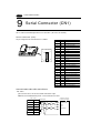
Serial Connector (CN1)
CN1 is used for communicating between a PC and a ZM-** (RS-232C, RS-422/485).
Serial Connector (CN1)
The pin arrangement of serial connector is as follows:
L
100240VAC
N
NC
CN1
CN1(Dsub 25pin 凹)
MJ2
1
MJ1
CN2
Signal
1
FG
Frame ground
2
SD
RS-232C send data
3
RD
RS-232C receive data
4
RTS
RS-232C RTS request to send
5
CTS
RS-232C CTS clear to send
Not used
6
14
SG
7
8
13
Contents
Pin No.
25
Signal ground
Not used
9
+5V
Not used
10
0V
Not used
11
Not used
12
+SD
13
-SD
14
+RTS
15
RS-422 send data (+)
RS-422 send data (-)
RS-422 RTS send data (+)
Not used
16
Not used
-RTS
RS-422 RTS send data (-)
18
-CTS
RS-422 CTS receive data (-)
19
+CTS
RS-422 CTS receive data (+)
17
20
Not used
21
Not used
22
Not used
23
Not used
24
+RD
RS-422 receive data (+)
25
-RD
RS-422 receive data (-)
Communication cable of RS-232C/RS-422
RS-232C
In case of RS-232C, SD and SG, and RD and SG form a pair.
Connect the shielded cable to pin No. 1 or the connector case cover.
ZM-** (CN1)
Signal
Pin No.
Shielded cable
To the RS-232C port
of the PC link module
FG
1
Receive data
SD
2
SG
RD
3
SG
RS
4
Send data
CS
5
SG
7
1 Serial Connector (CN1)
1 - 27
RS-422
In case of RS-422, +SD and -SD, and +RD and -RD form a pair.
Use SG if possible.
Connect the shielded cable to pin No. 1 or the connector case cover.
Use Terminal converter ZM-1TC which is the optional equipment in case of using terminal blocks in RS422/485 connection.
Specify terminal resistance by the dip switches on ZM-**. (Refer to the next page.)
ZM-** (CN1)
To the RS-422 port
of the PC link module
Shielded cable
Signal
Pin No.
FG
1
+RD
24
Send data (-)
-RD
25
Send data (+)
+SD
12
Receive data (-)
-SD
13
Receive data (+)
SG
7
SG
Terminal Blocks of RS-422/485
L
100240VAC
N
NC
CN1
When connecting at the terminal block, mount the
terminal converter ZM-1TC (sold separately) to
the serial connector (CN1).
The RS-422 signal wiring of ZM-1TC is connected
to the serial connector (CN1).
MJ2
MJ1
CN2
CN
1
SW
1
TB
1
ZM-1TC
CN1
SW1 (set to top:
4-wire connection)
RD+
Signal
Pin No.
FG
1
SG
7
+SD
12
RDSD+
SDSG
-SD
13
+RD
24
-RD
25
FG
Specify 4-wire connection or 2-wire connection by the dip switch on ZM-1TC (SW1).
(set to top: 4-wire connection)
ZM-1TC (Terminal Converter)
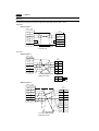
1 - 28
1 Setting of Dip Switches
10
Setting of Dip Switches
Setting of Dip Switches (DIPSW)
ON
1
Memory Extension 2
(invalid for ZM-42)
2
3
4
5
6
7
8
SD terminal resistance of pin No. 12 and 13 in CN1
Not used
RD terminal resistance of pin No. 24 and 25
Terminal resistance of MJ1(modular jack 1)
Setting of Terminal Resistance
• Set DIPSW 7 and 8 ON in case of connecting ZM-** to PC by 4-wire connection of RS-422/485.
• Set DIPSW 7 ON in case of connecting ZM-** to PC by 2-wire connection of RS-422/485.
• Set DIPSW 6 ON in case of connecting a card recorder (option) to Modular jack 1.
• The terminal resistance of Modular jack 2 is always ON.
Setting of Memory Extension 2 (This dip switch is invalid for ZM-42. Keep DIPSW 1 OFF.)
• Set DIPSW 1 ON in case of selecting “Memory Extension 2.”
(Refer to page 1-61, 1-62)
Keep DIPSW 2, 3, 4 and 5 (not used) OFF.
1 Modular Jack 1 & 2
11
1 - 29
Modular Jack 1 & 2
Modular Jack 1 & 2 (MJ1/2)
The right diagram is the pin arrangement
and the signal name of modular jack 1 &
2.
MJ1/2
12345678
Pin No.
1
2
3
4
5
6
7
8
Signal
+SD/RD
-SD/RD
+5V
+5V
0V
0V
RXD
TXD
External power supply
+5V
Max. 150mA
Setting of Modular Jack 1 & 2 (MJ1/MJ2)
Specify the use of MJ1/MJ2 by the screen edit software ZM-71SE.
Select [System Setting] from [Item], and click [Others]. The [Others] dialog is displayed. The setting
items of [Modular Jack 1] and [Modular Jack 2] in the [P2] menu are as follows.
Modular Jack 1
Modular Jack 2
[Editor port]
[Not used]
[Memory Card]
[Memory Card]
[Barcode]
[Barcode]
[V-I/O]
[V-I/O]
[Multi-Link]*1 *2
[Multi-Link]*1 *2
[Temp. CTRL Net]*2
[Temp. CTRL Net]*2
[ZM-Link]*2
[ZM-Link]*2
[Touch Switch]*3
[Touch Switch]*3
It is impossible to select both [Multi-Link] and [Temp. CTRL Net] in each setting of modular jack.
*1 It is possible to select this item when [Multi-Link 2] is selected for [Connection] and [Local Port] is set
to [1] in the [Comm. Parameter] dialog.
*2 [Multi Link 2 (master)] and [Temperature Control Network] and [ZM-Link] are available in the
following hardware version or later of ZM-**. As for ZM-42/43 series, any version can be used.
· Analog type : ZM-82T: D ZM-72TS : D ZM-72T : D ZM-72D : C ZM-52D : F
· Matrix type : All version
*3 As for [Touch Switch], refer to the “Analog RGB Input” manual.
Screen edit software transferring
Use modular jack 1 (MJ1) in case of editor transferring.
When [Editor port] is selected for [Modular Jack 1] in the [P2] menu, it is also possible to transfer the
data while running, because the auto change of the local mode and the run mode is valid.
When [Editor port] is selected, on-line editing and the simulation mode are also available.
When the item other than [Editor port] is selected for [Modular Jack 1] in the [P2] menu, be sure to
transfer the data by the software in the local mode. On-line editing and the simulation mode are not
available.
When the data is transferred by software, use the cable for data transferring which is the optional
equipment made by Sharp Corporation. (ZM-80C: option) to connect ZM-** to a personal computer.
1 - 30
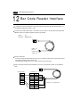
1 Bar Code Reader Interface
12
Bar Code Reader Interface
It is possible to receive the signal from a bar code reader by connecting a bar code reader to ZM-** via
the modular jack (MJ1/MJ2) of ZM-** series.
To connect a bar code reader to ZM-** via MJ1/MJ2, use the cable use the Bar Code Connecting Cable
ZM-80BC which is the optional equipment made only by demand.
: 2m
: Modular Plug
12345678
Length
Accessory
Brown : +5V
Red : 0V
Orange : RXD
Yellow : TXD
Notes on Connection
• In case of using the bar code reader which uses the CTS and RTS control, the bar code reader may not
work normally without jumping RTS and CTS.
• The output power supply (+5V) is max. 150mA. (Refer to the preview page.)
12345678
When the bar code reader connected to ZM-41/70 Series is used, connect it to ZM-** by the following
cable.
Barcode Reader
Signal
RTS
TXD
RXD
CTS
SG
+5V
D-sub 9pin(凹)
Pin No. Signal
1
CTS
2
RXD
3
TXD
4
RTS
5
6
7
SG
8
9
+5V
*
Orange : RXD
Yellow : TXD
* Jump pins, 1(CTS) and 4(RTS).
Red : 0V
Brown : +5V
1 Printer Interface (CN2)
13
1 - 31
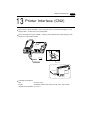
Printer Interface (CN2)
When a printer is connected to ZM-** via the connector (CN2), it is possible to hard-copy the screen
display of ZM-**, the data sheet, or the sampling data.
For the connection of the printer and ZM-**, apply the printer cable ZM-80PC (sold separately) which
matches the 36-pin parallel interface.
L
100240VAC
N
CN1
NC
MJ2
MJ1
CN2
to Printer
Half pitch 36 pins
Centronics
TB1
(+)
DC 24V
(−)
to Printer
CN2
ZM-42 Series
Compatible Printer Models
NEC
PC-PR201 series
EPSON
Compatibles with ESC/P24-J84, ESC/P-J84, ESC/P super function
HP(HEWLETT PACKARD) PCL Level 3
1 - 32
1 Video Interface
14
Video Interface
When a video or a CCD camera is connected to the optional ZM-** which has a video interface, the
image which is taken by a video or a camera is displayed directly in a screen of ZM-** series (only in case
of ZM-72TV/TVC, ZM-72TSV/TSVC, ZM-82TV/TVC).
Video Interface of ZM-** : BNC
L
N
100240VAC
NC
CN1
BNC
MJ2
MJ1
CN2
Video Display Specifications
Display Color
: 262,143 colors
Input Channel
: 4 Channels
Signal Form
: NTSC type, PAL type
Display Size
: 640 × 480, 320 × 240, 160 × 120 dots (possible to change the size)
Color Adjustment : contrast (256 steps), brightness (256 steps), color gain (256 steps)
* If you set the display size in 640 × 480 by ZM-72TV/TVC, you may not be able to use other switches
such as the one on the panel. (please apply 320 × 240 or 160 × 120 dot)
1 Connection
15
1 - 33
Connection
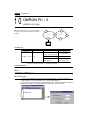
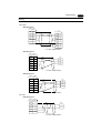
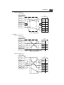
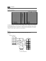
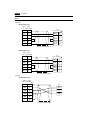
15-1 Connection with Sharp PLC
ZM-**
[1] 1 : 1 Link Communication
PLC
One ZM-** and one PLC are connected.
RS-232C or RS-422(RS-485)
[2] 1 : n Link Communication (Multi-drop)
One ZM-*2 and multiple PLCs are connected. (n = 1 to 32)
ZM-**
RS-485
Maximum length 500m
run
stop
PLC1
PLC2
PLC3
Available PLC for multi-link communication
Manufacturer
SHARP
MITSUBISHI
OMRON
HITACHI
MATSUSHITA
YOKOGAWA
YASKAWA
TOYOPUC
FUJI
Koyo
Allen-Bradley
GE Fanuc
TOSHIBA
SEIMENS
Kamigo
SAMSUNG
KEYENCE
LG
FATEK
IDEC
TAIAN
Models
JW series, JW70/100 COM port, JW20/30 COM port
An/A/N/U series, QnA series, Net10, FX series (A protocol)
SYSMAC C series, CV series, CQM1 series, CS1
HIDIC-H
MEWNET
FA500, FA-M3
Memobus
TOYOPUC
MICREX-F, FLEX-PC, NJ computer link
SU/SG, SR-T
PLC-5, SLC500, Micro Logix 1000
90 series
T series
S7-200 PPI
SELMART
SPC series, N plus, SECNET
KZ series, KV series
MASTER-K500 / K1000
FACON FB series
MICRO 3
TP02
General purpose serial
¥¥¥
¥¥¥
¥¥¥
¥¥¥
¥¥¥
¥¥¥
¥¥¥
¥¥¥
¥¥¥
¥¥¥
¥¥¥
¥¥¥
PLCn
¥¥¥
¥¥¥
¥¥¥
¥¥¥
1 - 34
1 Connection
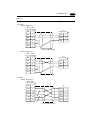
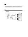
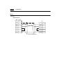
Multi-drop Communication (RS-485)
Refer to the PLC manual of each manufacturer for connection.
<E.g.>
The following example describes how one ZM-** is connected to three PLCs made by MITSUBISHI.
See MITSUBISHI’s manual for further details.
ZM-** (CN1)
Link module
Link module
Link module
Signal
Pin No.
Signal
Signal
Signal
FG
1
FG
FG
FG
+SD
12
RDA
RDA
RDA
-SD
13
RDB
RDB
RDB
+RD
24
SDA
SDA
SDA
-RD
25
SDB
SDB
SDB
SG
7
SG
SG
SG
SD/RD terminal resistance
(ON)
* Use twist shielded cable.
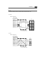
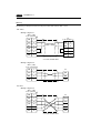
[3] n : 1 Link Communication (Multi-link 2)
(1) Multi-link 2
Up to 4 units can be connected to one PLC.
* Between a PLC and the ZM-** master station is the same as those for 1:1 communication.
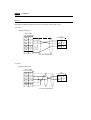
PLC
Communication between the ZM-** : RS-485 (2-wire system) Maximum length: 500 m
(b)
CN1
MJ2
ZM-** master
(Local Port 1)
terminal
(a)
(c)
(d)
CN1
ZM-** slave
(Local Port 2)
(e)
CN1
ZM-** slave
(Local Port 3)
CN1
ZM-** slave
(Local Port 4)
Available PLCs for multi-link 2.
As of January 2001, the PLCs supported are as follows. All the PLCs which are usable for 1:1
communication will be supported.
For the I/F driver, the Multi-Link 2 is supported by the version of 1.100 or later and as for a ZM-**
master station, make sure the hardware version of the unit is as follows.
As for ZM-42/43 series, any version can be used.
· ZM-82T series: D, ZM-82D series: C, ZM-72TS series:D, ZM-72T series: D, ZM-72D series: C,
ZM-52D series: F
* The Multi-Link 2 cannot be used with a Network module ZM-80NU.
1 Connection
<Type>
MITSUBISHI : AnA/N/U series
MITSUBISHI : QnA series
MITSUBISHI : ACPU Port
MITSUBISHI : FX series
MITSUBISHI : QnACPU Port
MITSUBISHI : QnHCPU Port (A)
MITSUBISHI : QnHCPU Port (Q)
MITSUBISHI : FX series(A prt)
MITSUBISHI : FX2N series
MITSUBISHI : FX1S series
OMRON : SYSMAC C
OMRON : SYSMAC CV
OMRON : SYSMAC CS1
SHARP : JW series
SHARP : JW100/70H COM Port
SHARP : JW20 COM Port
HITACHI : HIDIC-H
HITACHI : HIDIC-S10/2 alpha
HITACHI : HIDIC-S10/ABS
MATSUSHITA : MEWNET
YOKOGAWA : FA500
YOKOGAWA : FA-M3
YOKOGAWA : FA-M3R
YASKAWA : Memobus
YASKAWA : CP9200SH/MP900
TOYOPUC
FUJI : MICREX-F series
FUJI : MICREX-F series ZM70
FUJI : FLEX-PC series
FUJI : FLEX-PC CPU
FUJI : FLEX-PC COM
FUJI : FLEX-PC(T)
FUJI : FLEX-PC CPU(T)
FUJI : MICREX-F T link ZM70
1 - 35
<Type>
<Calendar>
KOYO : SU/SG
Depends on the model
KOYO : SR-T
Provided
KOYO : SR-T(K prt)
Not provided
A.B : PLC-5
Not provided
A.B : SLC500
Provided
A.B : Micro Logix 1000
Not provided
GE Fanuc : 90 series
Not provided
GE Fanuc : 90 series(SNP-X)
Not provided
TOSHIBA : T series
Provided
SIEMENS : S5/S7
Not provided
SIEMENS : S5/S7 ZM70
Not provided
SIEMENS : TI500/505
Provided
SIEMENS : S5 PG port
Not provided
SAMSUNG : SPC series
Not provided
SAMSUNG : SECNET
Depends on the model
KEYENCE : KZ series
Not provided
KEYENCE : KZ-A500 CPU Port
Provided
KEYENCE : KV series
Not provided
KEYENCE : KZ24/300 series CPU
Not provided
KEYENCE : KV10/24 series CPU
Not provided
LG : MASTER-K10/60/200
Not provided
LG : MASTER-K500/1000
Not provided
LG : LGMKX00S
Not provided
FANUC : Power Mate
Not provided
FATEK AUTOMATION: FACON FB series Provided
IDEC : MICRO3
Provided
MODICON : Modbus RTU
Depends on the model
YAMATAKE : MX series
Provided
TAIAN : TP02
Provided
<Calendar>
Provided
Provided
Provided
Depends on the model
Provided
Provided
Provided
Provided
Depends on the model
Provided
Depends on the model
Provided
Provided
Provided
Provided
Provided
Provided
Not provided
Not provided
Depends on the model
Provided
Provided
Provided
Depends on the model
Not provided
Provided
Provided
Provided
Provided
Provided
Provided
Provided
Provided
Provided
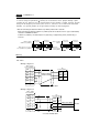
Example for wiring between ZM-**
Use the terminal converter (ZM-1TC), the optional equipment made by Sharp Corporation.
See Multi-link 2 instruction manual for further details.
* Wire the shielded FG only at the one of both sides so that they are not connected.
• When the ZM-1TC terminal converter is used.
Set the dip switch (SW1) of ZM-1TC as 2-wire connection.
(b)
ZM-** master
MJ1/2
(c)
Terminal block
prepared by user
Signal
+
-
SG
Terminal resistor
(ON)
+
-
SG
(d)
ZM-** slave
CN1+TC485
(e)
ZM-** slave
CN1+TC485
ZM-** slave
CN1+TC485
Signal
Signal
FG
FG
Signal
FG
+RD
+RD
+RD
-RD
-RD
-RD
+SD
+SD
+SD
-SD
-SD
-SD
SG
SG
SG
Terminal resistor
(OFF)
Terminal resistor
(OFF)
Terminal resistor
(ON)
• When the ZM-1TC terminal converter is not used.
Short-circuit between +RD and +SD, and -RD and -SD.
1 - 36
1 Connection
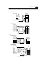
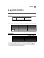
(2) Multi-link 2
Multiple ZM-** and a PLC are connected. (n=1 to 32)
ZM-** 1
ZM-** 2
ZM-** 3
ZM-** n
* The connections shown below
are not recommended.
RS-485
Maximum length 500m
PLC
Available PLCs for multi-link
When multiple ZM-** are connected to a link module of PLC
Manufacturer
SHARP
MITSUBISHI
MITSUBISHI
OMRON
HITACHI
Models
JW series(JW-10CM, JW-21CM, Z-331J/332J, ZW-10CM)
AnN, AnA, AnU series, Net10, FX series (A prt)
QnA CPU port (with ZM-1MD2)
SYSMAC C series, CV series
HIDIC-H
MATSUSHITA
YOKOGAWA
MEWNET
FA-M3
YASKAWA
TOYOPUC
FUJI
TOSHIBA
SIEMENS
SHINKO
SAMSUNG
LG
Memobus
TOYOPUC
MICREX-F, NJ computer link
T series
S7-200 PPI
SELMART
SPC series, N pius, SECNET
MASTER-K500 / K1000
In case of Sharp Corporation, only the link module correspondences to multi-link connection.
(The communication port etc. does not correspond.)
1 Connection
1 - 37
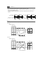
Use the terminal converter (ZM-1TC), the optional equipment made by Sharp Corporation for RS-485
connection.
• When the ZM-1TC terminal converter is used.
Set the dip switch (SW1) of ZM-1TC as 2-wire connection.
ZM-**+ZM-1TC
ZM-**+ZM-1TC
ZM-**+ZM-1TC
Link module
Signal
Signal
Signal
Signal
FG
FG
FG
FG
+SD
+SD
+SD
+RxD
-SD
-SD
-SD
-RxD
+RD
+RD
+RD
+TxD
-RD
-RD
-RD
-TxD
SG
SG
SG
SG
RD/SD terminal resistance
(ON)
RD/SD terminal resistance
(ON)
RD terminal resistance
(ON)
* Use twist shielded cable.
• When the ZM-1TC terminal converter is not used.
Short-circuit between +RD and +SD, and -RD and -SD.
When multiple ZM-** are connected directly to MITSUBISHI’s QCPU port
The optional equipment, ZM-1MD2 is required. Also, the use of the optional cable, MB-CPUQT which is
to connect ZM-1TC on ZM-** side to ZM-1MD2 on QCPU port side, is recommended.
• When the ZM-1TC terminal converter is used.
Set the dip switch (SW1) of ZM-1TC as 2-wire connection.
ZM-**+ZM-1TC
ZM-**+ZM-1TC
ZM-**+ZM-1TC
ZM-1MD2
ZM-Port
Signal
Signal
Signal
Pin No. Signal
FG
FG
FG
1
+SD
+SD
+SD
2
-SD
-SD
-SD
3
+TxD
+RD
+RD
+RD
4
+DSR
-RD
-RD
-RD
5
+DTR
SG
SG
SG
7
SG
15
-RxD
RD terminal resistance
(ON)
RD/SD terminal resistance
(ON)
RD/SD terminal resistance
(ON)
* Use twist shielded cable.
16
-TxD
17
-DSR
18
-DTR
20
21
MB-CPUQT
• When the ZM-1TC terminal converter is not used.
Short-circuit between +RD and +SD, and -RD and -SD.
+RxD
1 - 38
1 Connection
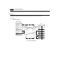
15-2 Connection to Ethernet/FL-net
When a network module ZM-80NU is mounted in ZM-43/52/72/82 series, it is connectable with
Ethernet/FL-net ( ZM-42 series is not connectable.)
In addition, in the program version 1.2.0.0 or later of ZM-43/52/72/82 series, the version 1.2.0.0 or
later of ZM-71SE corresponds to Ethernet/FL-net.
[1] In case of the Ethernet
(Personal computer)
ZM-71SE
Ethernet
ZM-**
PC applicable to Ethernet
ZM-**
PC applicable to Ethernet
RS-232C/RS-485
PC
PC corresponds to Ethernet
- Sharp : JW20H/30H [Ethernet module JW-255CM (10BASE5)]
JW50H/70H/100H [Ethernet module JW-51CM (10BASE5/10BASE-T)]
- Mitsubishi : QnA series/Q series
- Yokogawa : FA-M3
[2] In case of the FL-net
FL-net
PC applicable to FL-net
ZM-**
ZM-**
CNC
RC
PC corresponds to Ethernet
- Sharp : JW20H/30H [FL-net module JW-20FL5 (10BASE5)/JW-20FLT (10BASE-T)]
JW50H/70H/100H [FL-net module JW-50FL (10BASE5/10BASE-T)]
J-board [FL-net board Z-336J (10BASE5/10BASE-T)
- FL-net correspondence model in each company
1 Connection
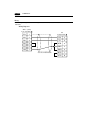
1 - 39
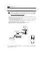
15-3 Connection by general purpose serial communication
The ZM-** can connected with a general purpose computer using the user program (exclusive
command use). Refer to ZM (general purpose serial) user’s manual in detail.
[1] When a computer and ZM-** are 1 : 1
- RS-232C can use it by less than 15m, and RS-422 (485) can use transmision distance by less than
500m.
- Interruption processing can be used. (Switch ON/OFF, the write-in key of a ten-key, screen change)
General purpose computer
ZM-**
1: 1 connection
RS-232C
RS-422
[2] When a computer and ZM-** are 1 : n (Up to ZM-** 32 sets are connectable.)
- The command point needs to be station number specified.
- Interruption processing cannot be used.(Switch ON/OFF, the write-in key of a ten-key, screen
change)
General purpose computer
1 : 1 connection
RS-422
ZM-**
ZM-**
ZM-**
1 Operation of ZM-** Main Menu
1 - 40
16
Operation of ZM-** Main Menu
When the power of ZM-** is turned ON for the first time, the screen on the below left is displayed. After
transferring the screen data to ZM-**, the following "Main Menu" is displayed.
When power is turned ON for the first time:
"Main Menu" after trasferring data
ZM-72T
Main Menu
System Information
SYSTEM PROG. VER.1.000
Screen Data
Information
Size :
786432
1998- 9- 1
FONT
VER.1.000/1.000/1.000
JAPANESE 32
07 : 23 : 30
I/F DRV VER. 1.000
Error: Stop
Time-Out: 0.50 sec
Retry: 3
PLC Type:
Comment:
Connection: 1 : 1
Signal Level: RS232C
PLC Stat.No.: 0
Editor : MJ1
Baud Rate: 19200
Data Length: 7
Stop Bit: 1
Parity: Even
Send Delay: 0msec
Memory-Card
I/O Test
If the screen data has been already transferred to ZM-**, press the [SYSTEM] switch, then press the [F1]
switch. The [Main Menu] is displayed.
the [SYSTEM] switch
The "Main Menu" is displayed.
the [F1] switch
S
Y
S
T
E
M
S
Y
S
T
E
M
M
O
D
E
M
O
D
E
ZM-72T
Main Menu
System Information
SYSTEM PROG. VER.1.000
Screen Data
Information
Size :
786432
FONT
VER.1.000/1.000/1.000
JAPANESE 32
07 : 23 : 30
I/F DRV VER. 1.000
Error: Stop
Time-Out: 0.50 sec
Retry: 3
PLC Type:
Comment:
Connection: 1 : 1
Signal Level: RS232C
PLC Stat.No.: 0
Editor : MJ1
1998- 9- 1
Baud Rate: 19200
Data Length: 7
Stop Bit: 1
Parity: Even
Send Delay: 0msec
Memory-Card
I/O Test
Main Menu
The "Main Menu" is the system menu for transferring the data between a personal computer and ZM-**.
When the screen data is transferred from a personal computer to ZM-**, the "Main Menu" must be displayed.
(If [Editor port] is selected for [Modular Jack 1] in the [P2] menu of the editing software or the on-line editing is
executed, it is not necessary to display the "Main Menu".
1 Operation of ZM-** Main Menu
System program version
1 - 41
Model name of ZM-**
Font data version
Data size
ZM-72T
Main Menu
System Information
SYSTEM PROG. VER.1.000
Screen Data
Information
Size :
PC type and comment
specified by the panel editor
786432
1998- 9- 1
FONT
VER.1.000/1.000/1.000
JAPANESE 32
Own Stat.No.: 1
V6 Total: 2
Retry: 10
PC I/F driver
version and name
Error: Stop
Time-Out: 0.50 sec
Retry: 3
PLC Type:
Comment:
Multi-Link
Multi-Link Network
Network
7 : 23 : 30
I/F DRV VER. 1.000
Connection: 1 : 1
Signal Level: RS232C
PLC Stat.No.: 0
Baud Rate: 19200
Data Length: 7
Stop Bit: 1
Parity: Even
Send Delay: 0msec
Setting of
comm. parameter
Multi-link setting
* This menu is displayed
only in case of selecting [1:1]
in [Connection] of [Comm. Parameter].
Editor : MJ1
Memory-Card
I/O Test
Setting of modular jack
b
a
"Main Menu" of ZM-42/43
Model name of ZM-42/43
System program version
a
Main Menu
ZM-42D
1998- 7 -23
12:24:30
b
SYS PROG. VER. 0.591
I/O Test
Font data version
FONT VER.1.000/1.010/1.000
JAPANESE 32
I/F DRV VER.1.000
Memory
-Card
c
Communication
Parameter
PC I/F driver
version and name
PLC Type :
Comment:
PLC type and
comment specified
by the panel editor
Editor:MJ1
Setting of modular jack
*
In case of ZM-42/43, when the “Communication Parameter” switch on the “Main Menu” is pressed, the
following “Comm. Param.” is displayed.
12:24:30
Main Menu
Comm. Param.
I/O Test
Screen Data Size :
Memory
-Card
Multi-Link Network
Communication
Own Stat.No. : 1
V6 Total : 2
Retry : 10
Parameter
Connection :
Signal Level :
PLC Stat. No.:
Baud Rate :
Data Length :
Stop Bit :
Parity :
Send Delay :
Press the "Communication
Parameter" switch.
Multi-link setting
* This menu is displayed
only in case of selecting
[1 : 1] in [Connection] of
[Comm. Parameter].
Editor:MJ1
786432
Error : Stop
Time-out : 0.50 sec
Retry : 3
Multi-Link N
RS232C
00
19200
7
1
Even
20 msec
1 Operation of ZM-** Main Menu
1 - 42
I/O Test
When the switch 'A' on the "Main Menu" is pressed, the following "I/O Test" is displayed.
This is the test menu to check only ZM-** hardware.
Memory-Card
I/O Test
B
E
C
Press the [I/O Test] switch.
D
I/O Test
Main Menu
SYS
F-1
Printer Check
Switch Check
F-2
A
F-3
Self-Loop Test
Please refer to the manual, "Hardware Specifications".
F-4
Communication Port
CTS
RTS
NG
OK
Self-Loop Test
*
F-5
CN1
RS-232C
MJ1
RS-485
F-6
MJ2
F-7
In case of ZM-42/43, when the switch “A” on the “Main Menu” is pressed, the following “I/O Test” is
displayed.
Then, the “Serial Test” switch on the “I/O Test” is pressed. The following “Serial Test” is displayed.
The self-loop test can be executed on this screen.
12:24:30
I/O Test
Memory
-Card
Press the "I/O Test" switch.
Communication
Parameter
E
I/O Test
Main Menu
D
A
Press the "Serial Test" switch.
Serial Test
SYS
I/O Test
Self-Loop Test
Please refer to the manual,
"Hardware Specifications".
F-1
Communication Port
Printer Check
F-2
CTS
RTS
F-3
NG
OK
F-4
Serial Test
Self-Loop
Test
Switch Check
F-5
C
B
CN1
RS232C
MJ1
RS485
MJ2
1 Operation of ZM-** Main Menu
1 - 43
A. Self-loop Test
This is the test menu to check the signals necessary for ZM-** to communicate with PC or a personal
computer by using only ZM-**.
Signal Test of RS-232C in CN1
Select [CN1] and [RS-232C] in [Communication Port] by pressing each switch.
Communication Port
CN1
RS-232C
MJ1
RS-485
MJ2
• Loop-back Test
Check the signals, [SD] and [RD].
1. Jump pins, 2 and 3 of CN1.
2. The test is OK, if the [OK] lamp turns ON when the [Self-Loop Test] switch is pressed.
CTS
RTS
CTS
RTS
NG
OK
NG
OK
Self-Loop Test
Self-Loop Test
• Test of CTS/RTS
Check the signals, [CTS] and [RTS].
1. Jump pins, 4(RTS) and 5(CTS) of CN1.
2. The test is OK if the [CTS] lamp and the [RTS] lamp turn ON at the same time that the [RTS] switch
is pressed. Similarly, the test is OK if the [CTS] turns OFF at the same time that the [RTS] is turned
OFF.
CTS
RTS
CTS
RTS
NG
OK
NG
OK
Self-Loop Test
Self-Loop Test
CTS
RTS
CTS
RTS
NG
OK
NG
OK
Self-Loop Test
Self-Loop Test
1 - 44
1 Operation of ZM-** Main Menu
Signal Test of RS-485 in CN1
Select [CN1] and [RS-485] in [Communication Port] by pressing each switch.
Communication Port
CN1
RS-232C
MJ1
RS-485
MJ2
• Loop-back Test
Check the signals, [SD] and [RD].
1. Jump each pin, 12 and 24, 13 and 25 of CN1.
2. The test is OK, if the [OK] lamp turns on when the [Self-Loop Test] switch is pressed.
CTS
RTS
CTS
RTS
NG
OK
NG
OK
Self-Loop Test
Self-Loop Test
• Test of CTS/RTS
Check the signals, [CTS] and [RTS].
1. Jump each pin, 14(+RTS) and 19(+CTS), 17(-RTS) and 18(-CTS) of CN1.
2. The test is OK if the [CTS] lamp and the [RTS] lamp turn ON at the same time that the [RTS] switch
is pressed. Similarly, the test is OK if the [CTS] turns OFF at the same time that the [RTS] is turned
OFF.
CTS
RTS
CTS
RTS
NG
OK
NG
OK
Self-Loop Test
Self-Loop Test
CTS
RTS
CTS
RTS
NG
OK
NG
OK
Self-Loop Test
Self-Loop Test
1 Operation of ZM-** Main Menu
1 - 45
Signal Test of RS-232C in MJ1 and MJ2
Select [MJ1] (or [MJ2]) and [RS-232C] in [Communication Port] by pressing each switch.
Communication Port
CN1
RS-232C
MJ1
RS-485
MJ2
• Loop-back Test
Check the signals, [SD] and [RD].
Execute the test by connecting the data transfer cable (ZM-80C) to CN1.
1. Set the adaptor, ADP25-9, which is attached to ZM-80C, to ZM-80C. And connect the modular jack
side of ZM-80C to MJ1 (or MJ2), ADP25-9 side of ZM-80C to CN1.
ZM-80C
CN1
MJ1/2
2. The test is OK, if the [OK] lamp turns on when the [Self-Loop Test] switch is pressed.
CTS
RTS
CTS
RTS
NG
OK
NG
OK
Self-Loop Test
Self-Loop Test
1 Operation of ZM-** Main Menu
1 - 46
B. Printer Check
Check the signal for a printer.
The test is OK if the test printout is executed satisfactorily when connecting ZM-** to a printer and
pressing this [Printer Check] switch.
[Example]
C. Switch Check
Check the reaction of the touch switches on the ZM-** panel.
When the [Switch Check] switch is pressed, the following screen is displayed.
The switch check screen is displayed.
Main Menu
SYS
X:
Y:
F-1
Check
Switch Check
F-2
Retu
Eras
Press the [Switch Check] switch.
Confirm that the color of the pressed area changes into white.
The white color means that the switch reacts to the touch normally.
Pressing the [F4] switch leads to the previous [I/O Test] screen.
Pressing the [F5] switch deletes all the white dots.
X:
Y:
Retu
Eras
1 Operation of ZM-** Main Menu
1 - 47
D. Test of SYSTEM & Function Switches
Check the eight switches (six switches for ZM-42/43) placed vertically on the right side of the ZM-**
panel.
The test is OK if the lamps on the screen turn ON when each switch is pressed.
SYS
SYS
F-1
F-1
F-2
F-2
F-3
F-3
The test is OK
when the [F-4] lamp is lit.
F-4
F-4
Press the [F4] switch.
F-5
F-5
F-6
F-6
F-7
F-7
E. Main Menu
Pressing this [Main Menu] switch leads to the previous [Main Menu].
The "Main Menu" is displayed.
Main Menu
SYS
ZM-72T
Main Menu
System Information
F-1
Check
Switch Check
F-2
SYSTEM PROG. VER.1.000
Screen Data
Information
Size :
786432
Own Stat.No.: 1
V6 Total: 2
Retry: 10
Editor : MJ1
1998- 9- 1
7 : 23 : 30
I/F DRV VER. 1.000
Error: Stop
Time-Out: 0.50 sec
Retry: 3
PLC Type:
Comment:
Multi-Link
Multi-Link Network
Network
Press the [Main Menu] switch.
FONT
VER.1.000/1.000/1.000
JAPANESE 32
Connection: 1 : 1
Signal Level: RS232C
PLC Stat.No.: 0
Baud Rate: 19200
Data Length: 7
Stop Bit: 1
Parity: Even
Send Delay: 0msec
Memory-Card
I/O Test
1 - 48
1 Operation of ZM-** Main Menu
Memory-Card
When the [Memory-Card] switch on the "Main Menu" is pressed, the following "Memory-Card" is displayed.
This screen is to transfer the screen data between ZM-** and a memory-card.
Memory-Card
I/O Test
The "Memory-Card" screen is displayed.
Press the [Memory-Card] switch.
Memory-Card
Main Menu
Port Selection
Modular Jack
MJ1
Memory-Card
Socket
Transfer
Display <--- Card
"Memory-Card" of ZM-42/43
Display ---> Card
Port Selection
Transfer
Modular Jack
MJ1
Display <-- Card
Data Selection
Screen Data
I/F Driver
Font Data
V6 Program
Display <--> Card
Data Selection
Main Menu
Memory-Card
Display --> Card
Screen Data
Font Data
Start
I/F Driver
V6 Program
Cancel
Display <-> Card
Start
Cancel
Procedure of Data Transferring
1) Port Selection
Select the [Modular Jack MJ1] switch (or [Modular Jack MJ2]) in case of using a modular jack.
Select the [Memory-Card Socket] switch in case of using a memory-card interface. When each switch is
pressed, the “Memory-Card Information” window is displayed.
In case of ZM-42/43, pressing the “Close” switch leads to the original screen after checking the memory
card information.
Memory-Card
Memory-Card
Port Selection
Modular Jack
MJ1
Memory-Card
Socket
Main Menu
Memory-Card Information
Close
Port Selection
V6 Program
:
Modular Jack
Memory-Card
Version:-.--MJ1
Socket
Font Data
:
Version:-.---/-.---/-.--I/F Driver
:
Version:-.--Screen PLC Type:
Screen Comment:
Data Selection
Transfer
Display <--- Card
Display ---> Card
Display <--> Card
Screen Data
Font Data
Start
I/F Driver
V6 Program
Cancel
In case of selecting [Memory Card] from [Modular Jack 2] in the [Others] dialog of
ZM-71SE, it is possible to select the [Modular Jack 2] switch in the [Port Selection] menu of the [Memory-Card] screen on ZM-**.
1 Operation of ZM-** Main Menu
1 - 49
2) Data Selection, Transfer
Pressing each switch leads to selection of the target for data transferring. (Possible to select multiple
items.)
Data Selection
Transfer
Memory-Card
Memory-Card
Main Menu
Close
Memory-Card Information
Main Menu
Close
Memory-Card Information
Port Selection
Port Selection
V6 Program
:
Modular Jack
Memory-Card
Version:-.--MJ1
Socket
Font Data
:
Version:-.---/-.---/-.--I/F Driver
:
Version:-.--Screen PLC Type:
Screen Comment:
V6 Program
:
Modular Jack
Memory-Card
Version:-.--MJ1
Socket
Font Data
:
Version:-.---/-.---/-.--I/F Driver
:
Version:-.--Screen PLC Type:
Screen Comment:
Transfer
Display <--- Card
Display ---> Card
Display <--> Card
Data Selection
Transfer
Display <--- Card
Display ---> Card
Display <--> Card
Data Selection
Screen Data
Font Data
Start
Screen Data
Font Data
Start
I/F Driver
V6 Program
Cancel
I/F Driver
V6 Program
Cancel
3) Start
When the [Start] switch is pressed, the data transferring starts. During data transfer, the character,
‘Start’, on the switch changes into the character, ‘Busy’, and the switch starts blinking.
After transferring data, the following message is displayed. Press the [OK] switch.
In the case of ZM-42/43, the “start” switch will be blinking as the data transfer starts.
During transferring
Start transferring
Memory-Card
Memory-Card
Main Menu
Memory-Card Information
Close
Data Selection
Screen Data
I/F Driver
Font Data
V6 Program
Close
Port Selection
Port Selection
V6 Program
:
Modular Jack
Memory-Card
Version:-.--MJ1
Socket
Font Data
:
Version:-.---/-.---/-.--I/F Driver
:
Version:-.--Screen PLC Type:
Screen Comment:
Main Menu
Memory-Card Information
V6 Program
:
Modular Jack
Memory-Card
Version:-.--MJ1
Socket
Font Data
:
Version:-.---/-.---/-.--I/F Driver
:
Version:-.--Screen PLC Type:
Screen Comment:
Transfer
Display <--- Card
Display ---> Card
Display <--> Card
Data Selection
Screen Data
Start
I/F Driver
Cancel
Transfer
Display <--- Card
Display ---> Card
Display <--> Card
Font Data
Busy
V6 Program
Cancel
Finish transferring
Memory-Card
Main Menu
Memory-Card Information
Close
Port Selection
V6 Program
:
Modular Jack
Memory-Card
Version:-.--MJ1
Socket
Font Data
:
Version:-.---/-.---/-.--I/F Driver
:
Version:-.--Screen PLC Type:
Screen Comment:
Data Selection
Transfer
Display <--- Card
Display ---> Card
Display <--> Card
WorkScreen
nomally
finished.
Data
Font Data
Start
I/F Driver
OK
V6 Program
Cancel
* When transfer the data from ZM-** to memorycard via the card interface(= [Memory-Card Socket]) of
ZM-**, use SRAM type memory card. FROM type memory card is not used.
1 - 50
1 Operation of ZM-** Main Menu
Message Display in Data Transferring
If an error occurs during transferring data, the message
display window shown on the right is displayed. The kinds
and the contents of the messages are as shown below.
Message
Work nomally finished.
OK
Contents
Work normally finished.
The specified operation has been concluded normally.
ZM-1REC not connecting
ZM-1REC is not connecting when selecting a modular jack.
ZM-1REC Communication Error
A communication error occurred between ZM-** and
ZM-1REC when selecting a modular jack.
Memory-Card not setting
A memory card is not inserted.
(Or in case of trying to write data into a memory card
when inserting FROM type memory card)
Memory-Card Capacity over
Cannot write the data into a memory card because
the data size in ZM-** is larger than the capacity of
a memory card.
Write Protect : ON
Cannot write data into a memory card because
the write protect switch in a memory card is ON.
Writing Error occurred.
The error occurred while writing data into a memory
card.
Selected data does not exist.
The data in the reading target does not exist.
ZM-** type is different.
The specified type of the data in ZM-** is different from
the type of the memory card data.
Selected data can not be read.
The data in a memory card cannot be read.
Reading Error occurred.
The error occurred during writing data into a flash
ROM of ZM-**.
Data discrepant
There is some discrepancy in data, when comparing data
between a memory card and ZM-**.
Screen data on ZM-** will be broken.
This message appears to inform the user that the data in
ZM-** will be broken by transferring the font data (the
size which is larger than the present data) from a memory
card to ZM-**. (The [OK] switch continues the transferring.
The [Cancel] switch stops transferring.)
Undefined Error occurred.
The error occurred due to some cause other than
the above mentioned.
1 Function Switches
17
1 - 51
Function Switches
Type
[SYS], [F1], [F2], [F3], [F4], [F5], [F6], [F7]
(ZM-42/43 : [SYS], [F1] to [F5])
S
Y
S
R
E
M
The [SYS] switch
By pressing this switch, the functions of the switches [F1] to [F7] are defined.
The type of the [SYS] switch is alternate. When this switch is pressed once, the switch
menu is displayed by the side of the function switches [F1] to [F5], and each function
switch corresponds to an item on the displayed switch menu.
When the [SYS] switch is pressed again, the switch menu which is displayed on the
screen will disappear, and the functions of switches [F1] to [F7] are defined for the
purpose of the user. The data of these function switches is allocated to the memory area
of PC.
M
O
D
E
B
A
C
K
L
T
Function of [F1] to [F5] when the switch menu is displayed
[F1] : Mode
This switch changes the operation mode.
Main Menu Mode --> RUN Mode
Run Mode --> Main Menu Mode (possible to specify the changing time)
[F2] : Contrast Adjustment (dark) ------- invalid in case of the TFT color type
This switch adjusts the contrast of LCD. When the [F2] switch is pressed once, the LCD color becomes
dark. If this switch is held down for 1 second, the LCD color changes rapidly into darkness.
[F3] : Contrast Adjustment (intermediate) ------- invalid in case of the TFT color type
This switch also adjusts the contrast of LCD. When the [F3] switch is pressed once, the LCD color
becomes intermediate.
[F4] : Contrast Adjustment (light) ------- invalid in case of the TFT color type
This switch adjusts the contrast of LCD. When the [F4] switch is pressed once, the LCD color becomes
light. If this switch is held down for 1 second, the LCD color changes rapidly into lightness.
[F5] : Backlight
This switch turns the backlight of ZM-** ON or OFF.
If you want to use this function, you have to set [Backlight] of the [Others] dialog in [System Setting].
The following list shows the backlight function specified in the editing software.
Backlight
ON
Auto 1
Auto 2
Manual
Function Switch (F5)
Ignored.
The following actions are added to the regular functions of these items :
Even if the time does not reach the setting time, the backlight will turn off if the
[F5] switch is pressed (provided that bit 11(Backlight) of Read Area n+1 is OFF
level). (Refer Instruction Manual)
If you select [Manual], the backlight will turn ON or OFF only when this switch is
pressed. Also, you can specify the item, [Backlight Power ON Time Control].
When you turn the power supply of ZM-** on ...
[ON] : the backlight is lit.
[OFF] : the backlight is off.
1 - 52
1 Terminal Converter (ZM-1TC)
18
Terminal Converter (ZM-1TC)
Use the terminal converter ZM-1TC when connecting the ZM-42/43/52/72/82 series and PC by the RS-422/
485 terminal block.
Size
25
65
34.7
Installation
(+)
DC24V
(−)
1. Make sure that the power of ZM-42/
43/52/72/82 series is OFF.
2. Install the ZM-1TC to the serial
connector (CN1) of the ZM-42/43/52/
72/82 series.
3. Settle the ZM-1TC by the module
mounting screw.
MJ1
CN1
MJ2
CN2
CN
1
Unit Mounting Screw
SW
1
TB
1
Unit Mounting Screw
ZM-1TC (Terminal Converter)
Tighten terminal screw, module mounting screw
Tighten mounting screws with the following torque.
Position of screws
Screw
size
Tighten torque
(N • m)
I/O, I/F terminal screw
M3
0.49
Module mounting screw
M2.6
0.1∼0.2
Pressure connection terminal
(Unit : mm)
5.9MAX
5.9MAX
• Never fasten these screws too tightly, otherwise the cover of Control Terminal may be deformed.
1 Terminal Converter (ZM-1TC)
1 - 53
Connection
Connecting the RS-422 communicating cable
• Choose 4-line or 2-line system by the ZM-1TC DIP switch (SW1)
• Connect the cable if SG exists.
• Connect the shield line to FG.
• End resistance is set by the dip switch located on the back side of ZM-** body.
• Be sure to put the attached cover to ZM-1TC when the connection is terminated.
ZM-1TC
SW1
(up…four-wire)
TB1
+RD
-RD
+SD
-SD
SG
FG
SW1 (Above: 4-line system
Below: 2-line system)
In the case of communicating one to the other
4-line system
2-line system
ZM-1TC
Signal name
ZM-1TC
To the RS4222 port of the
link module of the PC
Shield
Signal name
FG
Shield
To the RS4222 port of the
link module of the PC
FG
+RD
Communication data (+)
+RD
Sending/ receiving data (+)
-RD
Communication data (-)
-RD
Sending/ receiving data (-)
+SD
Communication data (+)
+SD
-SD
Communication data (-)
-SD
SG
SG
In case of multi-link
2-line system (in the case it has to jump on PC side)
ZM-1TC
Signal name
ZM-1TC
Shield
Signal name
ZM-1TC
Shield
Signal name
Shield
To the RS4222 port of the
link module of the PC
FG
FG
FG
+RD
+RD
+RD
Communication data (+)
-RD
-RD
-RD
Communication data (-)
+SD
+SD
+SD
Communication data (+)
-SD
-SD
-SD
Communication data (-)
SG
SG
SG
Ter mination resistance (on)
Ter mination resistance (off)
Ter mination resistance (off)
2-line system (in the case it doesn’t have to jump on PC side)
ZM-1TC
Signal name
ZM-1TC
Shield
Signal name
ZM-1TC
Shield
Signal name
Shield
To the RS4222 port of the
link module of the PC
FG
FG
FG
+RD
+RD
+RD
Sending/ receiving data (+)
-RD
-RD
-RD
Sending/ receiving data (-)
+SD
+SD
+SD
-SD
-SD
-SD
SG
SG
SG
Ter mination resistance (on)
Ter mination resistance (off)
Ter mination resistance (off)
1 Expansion I/O module (ZM-322M)
1 - 54
19
Expansion I/O module (ZM-322M)
The expansion I/O module ZM-322M is used on the ZM-72/82 series as the external I/O of the PC.
(Input 16 points, output 16 points)
Attached unit
• DI/DO connector
Used by connecting to the connector pin, and mounting it to the connection part of the expansion I/O
module.
Size
74
125.5
Expansion I/O module
25
E-I/O UNIT
Installation
Three parts of
screwing
ZM-322M
L
100240VAC
N
NC
CN1
• Take off the sticker to avoid the dust which is pasted on the back
side of the ZM-72/82 body, as described in the drawing. Then,
install ZM-322M by mounting three parts of the unit by the
screws.
• Install the DI/DO (attached unit) connector on the connection part
of ZM-322M, by mounting two parts of the unit by the screws.
Tighten screw of the module
Refer to the chart below for the use.
Screw position
Module mounting screw
MJ2
Screw size Tightening torque (N • m)
M3
MJ1
CN2
0.29∼0.49
Main body of ZM-72/82 series
1 Expansion I/O module (ZM-322M)
1 - 55
How to use
To use the ZM-322M, refer to the {[P2] menu} in [Chapter 2 System Setting] of the ZM-71SE instruction
manual.
Position of the DI/DO connector pin
DC24V
The positioning of the DI/DO connector pin is as follows.
Connect it by referring the drawing.
COM
IN
IN
IN
IN
IN
1
12
IN
13
22
IN
IN
IN
23
34
IN
DI/DO connector (attached connector)
Input
In No.
Pin No.
0
1
2
3
4
5
6
7
8
9 10 11 12 13 14 15
IN
IN
23 13 2 24 14 3 25 15 4 26 16 5 27 17 6 28
IN
IN
Output
OUT NO.
Pin No.
IN
0
1
2
3
4
5
6
7
8
IN
9 10 11 12 13 14 15
18 29 7 19 30 8 20 31 9 21 32 10 22 33 11 34
Input/output circuit
1
2
3
4
5
6
7
8
9
10
11
12
13
14
15
16
17
18
19
20
21
22
23
24
25
26
27
28
29
30
31
32
33
34
OUT
OUT
OUT
OUT
OUT
負荷
負荷
負荷
負荷
負荷
COM
DC24V
OUT
負荷
OUT
負荷
OUT
負荷
OUT
負荷
OUT
OUT
OUT
OUT
OUT
OUT
OUT
負荷
負荷
負荷
負荷
負荷
負荷
負荷
The circuit drawing of the input/output is as follows.
Input circuit
Output Circuit
Input voltage
Voltageless connection NPN type
12 to 24 VDC
Maximum Drive
50mA (12 to 24 VDC)
Input Impedance
Input electric current
3.3K
3 to 7mA
Remaining voltage
1.7V
12 to 24 VDC
OUT0
COM
Load
+
1.5k
IN0
Internal
circuit
22
Internal
circuit
OUT15
IN15
Load
+
-
3.3k
COM
12 to 24 VDC
1 - 56
1 Card Recorder (ZM-1REC)
20
Card Recorder (ZM-1REC)
Used for the backup of the panel data or recording the memory manager function and the data longing
function.
94
92
25
LED condition display
Modular connector
Memory card connector
AC adapter connector
Memory Card connector
SRAM and flash memory card are used as described in the chart below.
(JEIDA Ver4.0 Maker: ITT Canon)
SRAM card
256K, 512K, 1M, 2M, 4M Bytes
Flash memory card
256K, 512K, 1M, 2M, 4M, 16M Bytes
LED condition display
Display the battery voltage of the SRAM card.
Green: battery voltage normal
Red: battery voltage abnormal
Modular Connector
Connect with the ZM-42/43/52/72/82 series by the attached cable.
AC Adapter Connector
When using the external electricity, connect it to the AC adapter.
1 Cable for transporting the panel (ZM-80C)
21
1 - 57
Cable for transporting the panel (ZM-80C)
ZM-80C is the cable that transports panel data between ZM-42/43/52/72/82 series as well as ZM-41/70 series
and the personal computers.
When using, you need to have a Windows screen edit software ZM-71SE.
The convertible adapter ADP25-9 and ADP25-M are attached to ZM-80C.
Examples of the using cable and convertible adapter.
Types of
Computer
Serial Connector
Type
Control Terminal
ZM-42/43/52/72/82 Series
ZM-41/70
DOS/V
D-sub 9pin
Use the drawing (1)
Use the drawing (1) and (3)
PC98
D-sub 9pin
Use the drawing (1)
Use the drawing (1) and (3)
PC98
D-sub 25pin
Use the drawing (1) and (2) Use the drawing (1), (2) and (3)
(Reference) When constructing by using drawing (1) , (2) and (3), the functions are the same as our
product ZM-60C.
System Composition
ZM-42/43/52/72/82 Series
PC 98 Series
(D-sub 9 pin)
or
DOS/V personal computer
(1)
ZM-80C
(3)
ADP25-M
(2)
ADP25-9
ZM-41/70 Series
SYSTEM
F 1
F 2
D-sub 9pin
PC 98 Series
(D-sub 25 pin)
F 3
Modular
8pin
F 4
F 5
F 6
F 7
POWER
D-sub 25pin
D-sub 25pin
• The length of the ZM-80C cable is three meters.
RUN
1 - 58
1 Printer Cable (ZM-80PC)
22
Printer Cable (ZM-80PC)
ZM-80PC is the cable that connects ZM-42/43/52/72/82 series to the printer.
You can hard copy the panel of ZM-42/43/52/72/82 as well as registered list/ sampling data.
Printer
ZM-42/43/52/72/82 Series
Half pitch 36pin
Centronics 36pin
• The length of the ZM-80PC cable is 2.5 meters.
1 2 Port Adapter (ZM-1MD2)
23
1 - 59
2 Port Adapter (ZM-1MD2)
By mounting to the GPP port of Mitsubishi PC, ZM-1MD2 acts as an module that connects and communicates
between GPP (programming tool) and ZM-42/43/52/72/82 series.
Since it is possible to connect without the link module of the Mitsubishi PC calculator, the cost saving of the
hardware machines became possible.
Connection
Enlarged
drawing
Connector for GPP
G
P
P
(however, you can connect the Control Terminal)
GD
Connector for
CPU port
Connector for
ZM Series
Slide switch
Use when select the connection model.
1: A series (ACPU port)
2: CnA series (QnA CPU port)
3: FX series
(Note) Change the slide switch before
power supply.
MITSUBISHI A Series PC
Q Series
CPU
Connect the
connector which is
found on the back
side directly to the
CPU port.
GD
-M
DD
G
P
P
A6GPP, A7PHP,
personal computers, etc.
GD
SYSTEM
F 1
F 2
F 3
F 4
F 5
F 6
F 7
POWER
RUN
ZM Series
1 - 60
1 2 Port Adapter (ZM-1MD2)
When connecting 2 units together
MITSUBISHI A Series PC
Q Series
CPU
Connecting cable
(Mitsubishi made : optional)
SYSTEM
F 1
F 2
F 3
F 4
F 5
F 6
GD
G
P
P
F 7
POWER
This ZM
becomes a
bit faster
-M
RUN
ZM Series
DD
Connect the
connector which is
found on the back
side directly to the
CPU port.
GD
123
Slide switch
Use when select the connection model.
1: A series (ACPU port)
2: CnA series (QnA CPU port)
3: FX series
(Note) Change the slide switch
before power supply.
SYSTEM
F 1
F 2
F 3
F 4
F 5
F 6
F 7
POWER
RUN
ZM Series
Caution
1 Since the power supply of ZM-1MD2 is supplied from CPU, pay attention to capacity of 5V power supply
of CPU.
2 For wiring, it is fully careful to a noise.
3 There is the following restriction when ZM-1MD2 is used for QnA series CPU port.
1. When using it in ZM40/61 series, re-try time is 3 seconds.
The communication time out is 20 seconds between GPP and CPU.When any communication error
occurs between GPP and CPU, ZM-1MD2 maintains 20 seconds as communication time between
GPP and CPU.
After passing 20 seconds, although a communication port is changed to ZM between CPUs, since it is
3 seconds, the re-try time of ZM-40/60 series serves as a time-out, and a communication error occurs.
Perform re-execution 20 seconds after.
2. When you use it in ZM-41/70/80 series, choose from the two following methods.
- With the [Detail Setting] menu of the [Communication Parameter] of a [System Setup], [Communication
error processing] is set as "Continuation."
- [Time-out time]x [re-try time] may become more than 20 seconds.
3. Write in running
When the write-in operation in running is performed from GPP side and the time required is larger than
20 seconds, ZM-1MD2 cannot be used. In this case, written in STOP state for PC.
In addition, although the number of steps of the program which can perform writing among RUN in
less than 20 seconds has a difference according to the contents of a program, it is computable in the
following formula as a standard.
Time = (Number of steps ÷ 60) × scan time (msec)
A standard is asked in this formula. In addition, in the case of constant scan, this formula cannot apply.
4. When a power supply is switched on where a console is connected to the ZM-1MD2, a console will
become a communication time-out before completing initialization of the ZM-1MD2.
When it connects again or reset operation of a console is performed once it, removes the cable of a
console, it will return to a normal state. (Normal operation of this machine is carried out after 15 seconds
progress from the time of a power supply injection.)
4 When you use ZM-1MD2 for A series/FX series CPU, set time-out time as 1.5 seconds or more by commu
-nication parameter setup of ZM41/70/80.
1 2 Port Adapter (ZM-1MD2)
1 - 61
Attached metal fittings of ZM-1MD2
When connecting ZM-1MD2 to the small type (A1S, A2US, etc,) of A series PC made by Mitsubishi, use the
unit by mounting the attached metal fittings.
MELSEC Axsxxx
MELSEC AxS CPU
STOP
POWER
RUN
ERROR
L.CLR
RUN
RESET
RESET
MITSUBISHI
MITSUBISHI
GPP
Insert the metal fitting
as shown in the drawing.
Size of metal fitting
7
Tighten correctly
16
49
ON
Unused
(Used for A series large type,
or used when connecting to
Q series)
MELSEC Axsxxx
MELSEC AxS CPU
STOP
POWER
RUN
ERROR
MITSUBISHI
GPP
After inserting,
tighten it correctly
ON
L.CLR
RESET
RUN
RESET
MITSUBISHI
1 - 62
1 2Port Adapter (ZM-1MD2)
Size drawing of ZM-1MD2
4.1
24.1
4.1
100
GPP
74
1
ON
1
12.7
1
38.1
Devise mounting screw
Lot Seal
8.08
1 Expansion Memory (ZM-4EM)
24
1 - 63
Expansion Memory (ZM-4EM)
1
M
O
M
R
E
J
P
1
-M
7
9
V
F
C
N
C
1
Installation
P
0
2
0
0
4
F
R
O
M
0
About 900K bytes (1.2 M byte if 32 dot font is not in use) inside the flash memory that has been installed in
the main body of ZM-52/72/82 series are used as the panel data memory.
If you install ZM-2EM/4EM to the main body of ZM-52/72/82 series, an additional 2M/4M bytes are installed to
the panel data memory.(ZM-2EM is discontinued production.)
1. Turn OFF the power.
(1) Take off the cover
2. Take off the cover as described in the drawing, and
install the additional memory.
3. Turn ON the power.
* When installing the memory, press hard on both ends
of the cassette case.
(2) Install the
expansion memory.
L
100240VAC
N
CN1
NC
MJ2
How to use
MJ1
CN2
ZM-52/72/82
There are two ways of installing the additional
memory.
1) In the case of additional memory #1
In the case of expansion memory #2
The memory volume increases consequently as
ON
DIP SW
Turn on the DIP SW NO.1
the volume of the memory cassette increases, as
by lifting it up.
1 2 3 4 5 6 7 8
in the chart described below.
2) In the case of additional memory #2
Turn on the DIP SW NO.1 which locates on the back side of ZM-52/72/82 series.
Read the data (font, interface driver, panel data) other than the program already installed, to the
additional memory itself. The volumes of panel data are in the chart described below. (*2)
* When turning on the DIPSW NO.1, make sure that you also recharge the power of ZM-52/72/82 series.
ZM-52/72/82
Standard
Font
Japanese
Japanese 32 *3
English (Western)
Chinese (Mandarin)
Chinese (Simplified)
Korean
1,179,648
786,432
1,441,792
1,310,720
1,179,648
1,310,720
*1
*1
Additional
Additional
memory 1 + 2M memory 1 + 4M
3,260,416
5,357,568
2,867,200
4,964,352
3,522,560
5,619,712
3,391,488
5,488,640
3,260,416
5,357,568
3,391,488
5,488,640
*2
Additional
memory 2 2M
1,703,936
1,179,648
1,835,008
1,703,936
1,703,936
1,835,008
*2
Additional
memory 2 4M
3,801,088
3,276,800
3,932,160
3,801,088
3,801,088
3,932,160
*1 This is the volume of the panel data when adding the memory while turning off the DIP SW NO.1.
*2 This is the volume of the panel data when adding the memory while turning on the DIP SW NO.1.
*3 Japanese 32 matches to the 32 dot font. In the case of multiplying the size of the character, the
character becomes softened as the base is the 32 dot font.
Setting
On the screen edit software ZM-71SE, set [additional memory] to [2M(additional memory 1)] , [4M(additional
memory 1)] or [2M(additional memory 2)] , [4M(additional memory 2)] by using [other setting (O)/P1] of the
[system setting (A)].
1 - 64
1 Expansion Memory (ZM-43EM)
25
Expansion Memory (ZM-43EM)
An expansion memory ZM-43EM is the extension board used for which increases the screen data memory of
ZM-43T/43D/43L. When ZM-43T/43D/43L is mounted, 4 M bytes of screen data memory can be extended.
Correspondense models
ZM-43 series
(ZM-43T/43D/43L)
Software version
- Use the version 1.2.0.0 or later for program version (SYSTEM PROG.
VER.) of the ZM-43T/43D/43L.
- Use the verison 1.2.0.0 or later for ZM-71SE.
Installation
F
0
R
2
O
0
0
M
4
1
J
P
1
V
9
7
-M
E
M
C
N
C
1
P
F
R
O
M
0
Please install the ZM-43EM in ZM-43T/43D/43L (the following is ZM main body) in the following procedure.
1. Turn OFF the power.
2. Take off the cover of the cassette part for connect with expansion memory , and install the ZM-43EM.
When installing the memory, press hard on both ends of the ZM-43EM.
3. The DIP switch of the ZM main body side is set up according to the purpose of use.
Refer to the next page “Kinds of memory expansion”.
4. The power supply of ZM main body is turned ON.
(1) Take off the cover
(2) Install the expansion memory.
24VDC
MJ2
MJ1
CN1
CN2
ZM main body
In the case of expansion memory #2
ON
Turn on the DIP SW
NO.1 by lifting it up.
DIPSW
1 2 3 4 5 6 7 8
1 Expansion Memory (ZM-43EM)
1 - 65
Kinds of memory expansion
In the ZM-43EM, there are two kinds of extension methods (additional memory 1 and 2) according to setup
the DIP switch of ZM-main body.
1. Additional memory 1
Set OFF the DIPSW “1” of ZM main body.
- As shown in the following table (*1), the amount of memories increases by the capacity of ZM-43EM.
2. Additional memory 2
Set ON the DIPSW “1” of ZM main body.
- Data (font, I/F driver, screen data) other than the program of ZM main body is written in ZM-43EM.
- The capacity of screen data is as shown in the following table (*2).
Standard
Font
Japanese
Japanese 32 *3
English (Western)
Chinese (Mandarin)
Chinese (Simplified)
Korean
1216
768
1408
1280
1216
1344
*1
Additional
memory 1
5248
4800
5440
5312
5248
5376
*2
Additional
memory 2
3712
3264
3904
3776
3712
3840
(Unit : K bytes)
*1 This is the volume of the panel data when adding the memory while turning off the DIP SW "1".
*2 This is the volume of the panel data when adding the memory while turning on the DIP SW "1".
*3 Japanese 32 matches to the 32 dot font. In the case of multiplying the size of the character, the
character becomes softened as the base is the 32 dot font.
(Note ) When turning ON or OFF the DIPSW “1”, make sure that you also recharge the power of ZM
main body.
Setting of ZM main body
On the screen edit software ZM-71SE, set [additional memory] to [4M(additional memory 1)] or [4M(additional
memory 2)] by using [other setting (O)/P1] of the [system setting (A)].
1 - 66
1 Expansion Memory (ZM-43SM, ZM-80SM)
26
Expansion Memory (ZM-43SM, ZM-80SM)
An expansion memory ZM-43SM/80SM is a memory for extension in which the calendar and SRAM backup
memory of ZM-43/52/72/82 were carried.
Model name
Correspondense model
ZM-43SM
ZM-43 series
ZM-80SM
ZM-52/72/82 series
- This expansion memory cannot be used for
ZM-42 series.
The component of ZM-43SM/80SM is as follows.
ZM-43SM ZM-80SM
Accessories
・Coin type lithium primary battery (type : CR2430): 1
・Caution seal: 1
Safety precautions
Since the lithium battery used by ZM-43SM/80SM contains inflammable substances, such as lithium and organic solvent, if handling is mistaken, by generation-of-heat / burst ignition etc., it is injured or it has a possibility
of resulting in a fire.
Caution
- Perform exchange of a battery after discharging static electricity collected on the human body.
- Use the battery of appointed "form" and a "model name" at the time of exchange of a battery.
If other batteries are used, it will become the cause of a fire or explosion.
- If it works hard with the battery single article currently used for this equipment, it will become the cause
of causing a fire and chemical combustion.
- Do not put in a battery into fire, or do not heat and decompose.
- For a terminal, please twist a tape, insulate and dispose of a used battery correctly.
- Keep a battery to the place which does not reach an infantile hand. (If you should understand, please
consult with a doctor immediately.)
- Do not make a battery short-circuit.
- Do not charge a battery by any means.
- Do not carry out direct soldering to a battery.
- Make + and - of a battery reverse and do not use them.
- Since there is a possibility of igniting in escaped electrolysis liquid when a battery leak or there is a nasty
smell, please keep away from fire immediately.
Handling precautions
Be sure to attach a battery when you are used ZM-43SM/80SM. Since the data of ZM-43SM/80SM is not held
unless a power supply is supplied to ZM-43SM/80SM.
Use as for the version 1.1.0.2 or later for ZM-71SE, version1.200 or later, as for the program version of ZM-43/
52/72/82, version1.100/1.090/1.000 or later, as for font data version.
1 Expansion Memory (ZM-43SM, ZM-80SM)
1 - 67
Installation
Please attach ZM-43SM/80SM in ZM-43/52/72/82 in the following procedure.
i
J A PA N
SANYO
+
CR2430
CE
TS
M n O 2- L
1. The battery (CR2430) of an attached article is turned to the socket of ZM-43SM/80SM, "+" side is turned
upwards, and it sets. In case it sets, as a battery is pushed in a plug and the direction of "+" side, "-" side
also inserts it in "+" side.
LL
3VO
L
Type :ZM43SM/RS
Lot No :XXXXXXX
+ side
SANYO
M n O 2- L
JA P A N
+
+
CR2430
i
CE
+
TS
-
LL
3 VO
L
2. The date of five years after is entered in the "next battery exchange day" column of the cautions seal of an
attached article, and as shown in the following figure, it sticks on it.
Ty
p
Lo e :Z
tN
M
Se
o :X -43
ins e op
XX SM/R
e
XX
ba tructi rati
XX S
n
tt
電 ery on fo g or
池
の to b r ty main
を
e u pe
種
参
類
Ba 照
of tena
に se
し
nc
次 ttery て下 つい d.
e
回
電 repla さい ては
池
取
交 cem 。
扱
換
説
日 ent.
明
YY
書
YY
, M
M
,D
D
Type :ZM-43SM/RS
Lot No :XXXXXXX
+
+
CR2430
iC
ELL
J A PA N
SANYO
See operating or maintenance
instruction for type of
battery to be used.
電池の種類については取扱説明書
を参照して下さい。
Battery replacement.
次回電池交換日
,
,
+
+
TS
M n O 2- L
-
3VO
L
[Caution seal]
Write the date of five years after.
- The term of validity of the battery of ZM-43SM/80SM is about five years at 25 degrees. Even if it
was less than five years, when the voltage of a battery falls, the 4th bit of the internal memory
(address #s167) of ZM-43/52/72/82 turns ON, and it warns of battery exchange. Please exchange
batteries quickly.
MSB
$s167
LSB
15 14 13 12 11 10 09 08 07 06 05 04 03 02 01 00
0
0
0
0
0
0
0
0
0
0
0
0
Reserve memory cassette
information (Setting : 0)
0
0 : Not installed
1 : Expansion memory (2M)
2 : Expansion memory (4M)
3 : SRAM+ clock cassette
Reserve memory cassette information (Setting : 0)
1 : Battery failure (Necessory to exchange the battery.)
3. The power supply of ZM-43/52/72/82 is turned OFF.
4. The cover of an expansion memory cassette part is removed and ZM-43SM/80SM is attached.
Typ
Lo e :V
tN
6E
See
o :X M
inst op
XX /RS
er
XX
ba ruct atin
XX
tte ion
g
電
fo or
池 ry
を の to be r type mai
参 種
nt
Bat 照 類に used of en
an
し
ce
次 tery て下 つい .
回
電 repl さい ては
池
ac
。 取
交
扱
換 emen
説
日
明
YY t.
書
YY
, M
M
,D
D
1. Take off the cover.
2. Install the SRAM casette.
L
100240VAC
N
CN1
NC
MJ2
MJ1
CN2
ZM main body (The above diagram is ZM-72/82)
Setting of ZM main body
In screen edit software ZM-71SE, [SRAM cassette setup (W)] of a [System setup(A)] is chosen, and [SRAM
cassette setting] dialog is set up. When you change a setup, please be sure to format.
The following procedure performs adjustment and a format of the date of ZM-43SM/80SM, and time.
1. The [local main] screen of ZM-43 main part is displayed.
2. The "cassette adjustment" switch of a [local main] screen is pushed.
3. A [cassette adjustment] screen is displayed. Adjustment and a format of a date and time are performed here.
1 - 68
1 Expansion Memory (ZM-43SM, ZM-80SM)
The exchange method of a battery
You should prepare the following battery for exchange, and it exchanges for it in the following procedure.
Model type
CR2430
Specifications
・Coin type lithium primary battery (recommend : made by SANYO)
1 In case battery exchange is carried out, ZM-71SE are used (cable : ZM-80C) and backup of the data
stored in ZM-43SM/80SM is taken.
1. ZM-71SE is started.
2. [Transmission] icon is clicked. [Transmission] dialog is displayed.
3. A [transmission device:main part] and [transmission data:SRAM data] are chosen. When taking
backup by from ZM-71SE to Ethernet on a server, IP address] of transmission / SRAM wearing ZM
main body is chosen by [Ethernet. The item [which uses a simulator] and [which takes in a comment
at the time of reception] is left as it is.
4. [PC] button of the [transmission method] is clicked.
5. The read data is saved at [*.RAM] file.
2 If the power supply of ZM main body is turned OFF and the cautions seal of ZM-43SM/80SM is removed,
the battery mounted in the socket will appear. A battery is removed from a socket and exchanged for a
new battery. (Refer to previous page “Installation”.)
3 The power supply of ZM main body is turned ON and RAM file saved by 1 is transmitted to ZM-43SM/
80SM.
Specifications
● General specifications
Item
Power
Model
Operation temperature
ZM-43SM
ZM-80SM
3.3 VDC (Power supply from ZM-43/52/72/82)
0℃ to +50℃
Circumference temperature
-10℃ to +60℃
Relative humidity
85% RH max. (non condensation)
Dust
Not dust
Corrosive gas
Without corrosive gas
Outside dimensions W×H(mm)
50 × 57.5
Case color
Black
Material
PC/ABS resin
Gray
● Memory specifications
Specifications
Item
Kinds of memory
SRAM
Memory capacity
512 Kbytes
● Backup specifications
Item
Battery speicifications
Specifications
Coin type lithium primary battery
Battery type : CR2430 (recommend: Sanyo)
Backup term
About five years
(Circumference temperature : 25℃)
Exchange propriety
Available (install in socket for battery)
Battery voltage sag
detection function
Provided (Internal memory allocation)
Calender accuracy
Monthly difference ±60 seconds
(Circumference temperature : 25℃)
(Note)
When ZM-43/52/72/82 series and a printer are always connected and ZM-43SM/80SM is being used at the time
of use, in case you turn off the power supply of ZM main body, please be sure to turn off the power supply of a
printer.If the power supply of a printer is changed into ON state, in response to a surroundings lump and its
influence, the consumption current of the backup battery of ZM-43SM/80SM will increase the voltage from the
signal line of a printer, and a backup battery will be exhausted in 2 to 3 months.
Connection to
Link Module
1. Sharp PC
2. MITSUBISHI PC • 1
3. MITSUBISHI PC • 2
4. MITSUBISHI PC • 3
5. MITSUBISHI PC • 4
6. MITSUBISHI PC • 5
7. MITSUBISHI PC • 6
8. MITSUBISHI PC • 7
9. OMRON PC• 1
10. OMRON PC• 2
11. HITACHI PC • 1
12. HITACHI PC • 2
13. Matsushita PC
14. YOKOGAWA PC • 1
15. YOKOGAWA PC • 2
16. YASKAWA PC • 1
17. YASKAWA PC • 2
18. TOYOPUC PC
19. FUJI PC • 1
20. FUJI PC • 2
21. FUJI PC • 3
22. FUJI PC • 4
23. Koyo PC
24. Allen-Bradley PC • 1
25. Allen-Bradley PC • 2
26. GE Fanuc PC • 1
27. GE Fanuc PC • 2
28. TOSHIBA PC
29. TOSHIBA MACHINE PC
30. SIEMENS PC • 1
31. SIEMENS PC • 2
32. SIEMENS PC • 3
33. SIEMENS PC • 4
34. SIEMENS PC • 5
35. Shinko PC
36. SAMSUNG PC
37. KEYENCE PC• 1
38. KEYENCE PC• 2
39. KEYENCE PC• 3
40. LG PC
41 . FANUC PC
42. FATEK AUTMATION PC
43. IDEC PC
44. MODICON PC
45. YAMATAKE PC
46. TAIAN PC
2 Sharp PC
1
Sharp PC
Link module
The following are the link module and communication port that are possibly connected.
PC
Link module
W70H, W100H
JW50, JW70, JW100
JW50H, JW70H, JW100H
ZW-10CM
JW-10CM
JW20, JW20H
JW30H
JW-21CM
JW10
JW-1324K/1342K
JW-1424K/1442K
JW-1624K/1642K
MMI Port
Communication Port
J-board
Z-331J/332J
JW70(JW-70CU)
JW100(JW-100CU)
JW70H(JW-70CUH)
JW100H(JW-100CUH)
Communication Port
ZM-71SE Model Setting
JW Series
JW70H COM
JW20(JW-22CU)
JW20H(JW-22CU)
JW30H
JW-32CUH/H1
JW-33CUH/H1/H2/H3
PG/COMM1 Port
PG/COMM2 Port
JW20 COM
J-board
(Z-311J
Z-312J)
Upper Communication Port CN3
Upper Communication Port TC1
(Z-511J)
Upper Communication Port CN8
Upper Communication Port TC12
(Z-512J)
PG/COMM1 Port
PG/COMM2 Port
The setting items are described in the chart below.
Item
Baud Rate
Content of settings
Same as the main unit (normal 19200bps)
Data Length
7 bit
Parity
Even
Stop Bit
2 bit
Error Check
Sumcheck
RS-422
4-wire system
Transmission Control
Command mode
Port
[01] fix
2-1
2-2
2 Sharp PC
Switch Setting of Link module
(1) Switch setting of ZW-10CM, JW-10CM and JW-21CM
Contents
Switch
Setting
SW0
4
Comand mode
SW1
1
Station address (lower half)
SW2
0
Station address (upper half)
OFF
Not used
SW3-2
ON
4-wire system
SW3-3
OFF
Not used
SW3-4
ON
Even parity
SW3-1
SW4
0
SW7
ON
Baud rate:19200 bps
Temination resistance provided
(2) Switch setting of Z-331J/332J
Switch
Setting
SW0
4
Computer link
SW1
1
Station address (lower half)
SW2
0
Station address (upper half)
Contents
SW3-1
OFF
Not used
SW3-2
OFF
Used only for 2-line system
SW3-3
OFF
Not used
SW3-4
ON
Even parity
SW4
0
SW7
ON
Baud rate:19200 bps
Temination resistance provided
PC System Memory Setting [in case of a communication port]
(1) System memory setting of JW-70CU/100CU, JW-70CUH/100CUH and Z-311/312J
System memory
Setting
Contents
Stop bit : 2 bit,
#236
30 (H)
Parity : Even
Baud rate:19200 bps
#237
01 (H)
Station address
2 Sharp PC
(2) System memory setting of JW-32CUH/H1/M1, JW-33CUH/H1/H2/H3, Z-51J/512J
• Communication port 1 (PG/COMM 1 port)
System memory
Setting
#234
30 (H)
Contents
Stop bit : 2 bit,
Parity : Even
Baud rate:19200 bps
#235
01 (H)
Station address
• Communication port 2 (PG/COMM 2 port)
System memory
Setting
Contents
Stop bit : 2 bit,
#236
30 (H)
#237
01 (H)
Parity : Even
Baud rate:19200 bps
Station address
(3) System memory setting of JW-1324K/1342K, JW-1424K/1442K and JW-1624K/1642K
• Communication port
System memory
Setting
#234
00 (H)
Contents
Computer link
Stop bit : 2 bit,
Parity : Even
#236
30 (H)
Baud rate:19200 bps
Data Length : 7 bit
#237
01 (H)
System memory
Setting
Station address
• MMI port
Contents
Stop bit : 2 bit,
Parity : Even
#226
30 (H)
#227
01
Baud rate:19200 bps
Data Length : 7 bit
(H)
Station address
2-3
2-4
2 Sharp PC
Available Memory
Memory
Bit Write
X9XXX (Register)
XXXXX (Relay)
EXXXX (Register [Self-diagnosis])
bXXXX (Timer/Counter [current value)
F1 (File Register)
F2 (File Register)
F3 (File Register)
Available:
Unavailable:
TYPE
Remarks
0
1
2
3
4
5
6
as word device
[Caution]
Pay attention to the following cautions when applying the indirect address-assign of the macro command
by the register x9xxx(memory type :0)
(Refer to P14-23 of the ZM-71SE instruction manual)
1) When applying the ZM-70/41
At least before V1.10 or after V1.15 of the system ROM version (You can not use V1.11~ V1.14
versions) The memory-assign method between the register 09000 to 19000 is done by the 512-word
unit.
2) When applying the ZM-82/72/52/43/42, ZM-71T
The memory-assign method between the register 09000 to 19000 is done by the 256-word unit
regardless of versions.
The relation between the register address and the memory No.(in the case
of indirect address- assign)
(the memory no. is shown by the word unit.)
Model
ROM Version
Register address
09000~09776
19000~19776
29000~29776
39000~39776
49000~49776
59000~59776
69000~69776
79000~79776
89000~89776
99000~99776
ZM-70/41
before V1.10 and
after V1.15
Memory No (DEC)
0~255
512~767
1024~1279
1536~1791
2048~2303
2560~2815
3072~3327
3584~3839
4096~4351
4608~4863
ZM-82/72/52/43/42
ZM-71T
all versions
Memory No (DEC)
0~255
256~511
512~767
768~1023
1024~1279
1280~1535
1536~1791
1792~2047
2048~2303
2304~2559
2 Sharp PLC
Wiring
Indicate the connection of ZM-** and each module. CN1 is used alternately with RS-422.
RS-422
• Connection with ZW-10CM, JW-10CM and JW-21CM
ZW-10CM
JW-10CM
JW-21CM
ZM-** (CN1)
Signal name
No.
Signal name
+SD
12
L3
-SD
13
L4
+RD
24
L1
-RD
25
L2
FG
1
SHIELD
* Use twist shielded cables
GND
Earth
• Connection with JW-70CU/100CU, JW-70CUH/100CUH, JW-22CU
ZM-** (CN1)
JW-22CU
JW-70CU/100CU
JW-70CUH/100CUH
(Communication Port)
Signal name
No.
Signal name
No.
+SD
12
RXD
12
-SD
13
RXD
13
+RD
24
TXD
10
-RD
25
TXD
11
FG
1
FG
1
* Use twist shielded cables
(Attention : In the case of JW-70CUH/100CUH, connect the end resistance.)
(Connect the pin No.6 of the communication port with the pin No.13.)
• Connection with Z-311J/312J
ZM-** (CN1)
Z-311J/312J
(Host communication port TC1)
Signal name
No.
Signal name
No.
+SD
12
RD
3
-SD
13
RD
4
+RD
24
TD
1
-RD
25
TD
2
FG
1
FG
5
* Use twist shielded cables
• Connection with Z-511J
ZM-** (CN1)
Z-511J
(CN8 or CN12)
Signal name
No.
Signal name
+SD
12
RD(+)
9(4)
-SD
13
RD(-)
10(5)
No.
+RD
24
SD(+)
3(2)
-RD
25
SD(-)
11(3)
FG
1
FG
1(1)
* Use twist shielded cables
CN12 number in parentheses of No.
2-5
2-6
2 Sharp PLC
• Connection with JW-32CUH/H1, JW-33CUH/H1/H2/H3, Z-512J
ZM-** (CN1)
JW-32CUH/H1
JW-33CUH/H1/H2/H3
Z-512J
PG/COMM1 Port
PG/COMM2 Port
Signal name
No.
Signal name
+SD
12
RD (+)
No.
9
-SD
13
RD (-)
10
+RD
24
SD (+)
3
-RD
25
SD (-)
11
FG
1
FG
1
* Use twist shielded cables
• Connection with JW-1324K/1342K, JW-1424K/1442K, JW-1624K/1642K
[In case of connecting to the communication port]
ZM-** (CN1)
Signal name
No.
+RD
24
+SD
12
-RD
25
-SD
13
FG
1
JW-1324K/1342K
JW-1424K/1442K
JW-1624K/1642K
(Communication Port)
Terminal name
L1
L2
SHLD
* Use twist shielded cables
(Attention : set the termination resistance switch naught (off) at the termination resistance)
[When connecting to MM1 port]
ZM-** (CN1)
JW-1324K/1342K
JW-1424K/1442K
JW-1624K/1642K
(MMI Port)
Signal name
No.
+SD
12
RX
2
-SD
13
RX
7
+RD
24
TX
3
-RD
25
TX
8
FG
1
* Use twist shielded cables
Signal name
No.
PG COM
4
GND
5
(Attention: set the termination resistance switch naught (off) at the termination resistance)
• Connection with Z-331J/332J
ZM-** (CN1)
Signal name
No.
+RD
24
+SD
12
-RD
25
-SD
13
FG
1
* Use twist shielded cables
Z-331J/332J
(Host communication port T1)
Terminal name
L1
L2
S
FG
2 Sharp PLC
RS-232C
• Connection with JW-70CU/100CU, JW-70CUH, JW-22CU
ZM-** (CN1)
JW-22CU
JW-70CU/100CU
JW-70CUH/100CUH
(Communication Port)
Signal name
Pin No.
Signal name
Pin No.
FG
1
FG
1
SD
2
RXD
3
RD
3
TXD
2
RS
4
SG
CS
5
SG
7
Short Terminal
7
12
14
* Used shielded cables
• Connection with Z-311J/312J
ZM-** (CN1)
Z-311J/312J
(Host communication port T1)
Signal name
Pin No.
Signal name
Pin No.
FG
1
FG
1
SD
2
RDC
3
RD
3
TDC
2
RS
4
GND
7
CS
5
SG
7
Short Terminal
6
8
* Used shielded cables
• Connection with JW-32CUH/H1, JW-33CUH/H1/H2/H3
ZM-** (CN1)
Signal name Pin No.
JW-32CUH/H1
JW-33CUH/H1/H2/H3
(PG/COMM2 port)
Signal name
Pin No.
FG
1
FG
1
SD
2
RD
4
RD
3
SD
2
RS
4
SG
7
CS
5
SG
7
* Use twist shielded cables
2-7
2-8
2
2 MITSUBISHI PC • 1
MITSUBISHI PC • 1
(A/Q series link unit)
Available PC
ZM-71SE
Model Setting
PC
A2A, A3A
Link Unit
AJ71C24-S6
AJ71C24-S8
AJ71UC24
A2U, A3U, A4U
AJ71UC24
A1, A2, A3
A1N, A2N, A3N
A3H, A3M, A73
AJ71C24
AJ71C24-S3
AJ71C24-S6
AJ71C24-S8
AJ71UC24
AnA/N/U
series
A0J2, A0J2H
RS-232C [Wiring Diagram 2]
RS-422 [Wiring Diagram 3]
A0J2C214-S1
A1SJ71UC24-R2
RS-232C [Wiring Diagram 1]
A1SJ71UC24-R4
RS-422 [Wiring Diagram 3]
A1SJ71UC24-PRF
RS-232C [Wiring Diagram 1]
A1SJ71C24-R2
RS-232C [Wiring Diagram 1]
A1SJ71C24-R4
RS-422 [Wiring Diagram 3]
A1SJ71C24-PRF
RS-232C [Wiring Diagram 1]
A2CCPUC24
CPU built-in port
RS-232C [Wiring Diagram 1]
QnH(A mode)
A1SJ71UC24-R2
A1SJ71UC24-R4
RS-232C [Wiring Diagram 1]
RS-422 [Wiring Diagram 3]
A2US
A1S, A1SJ, A2S
AJ71QC24N
QnA
series
Wiring Diagram
(refer to P2-12, 13)
Q2A, Q3A, Q4A
Q2ASx
AJ71QC24
A1SJ71QC24
QnH(Q mode)
RS-232C [Wiring Diagram 2]
RS-422 [Wiring Diagram 3]
RS-232C [Wiring Diagram 2]
RS-422 [Wiring Diagram 3]
RS-232C [Wiring Diagram 1]
RS-422 [Wiring Diagram 3]
AJ71QC24-R4(CH1)
RS-422 [Wiring Diagram 4]
AJ71QC24-R4(CH2)
RS-422 [Wiring Diagram 3]
QJ71C24
RS-232C [Wiring Diagram 1]
RS-422 [Wiring Diagram 3]
2 MITSUBISHI PC • 1
2-9
Communication Setting
The recommended communication parameter setting of both PC and ZM-** is as follows:
A series link unit
Setting of PC
Comm. Parameter of ZM-**
Baud Rate
19200bps
19200bps
Port
0 for both STATION × 10 and ×1
0
Item
Parity
*1
Even
Even
MODE1
Trans. Mode 1
Transmission
Control Mode
RS-232C
RS-422
MODE5
Trans. Mode 1
Transmission
Code
Data Length
7 (ASCII)
7
Stop Bit
1
1
Sumcheck
Provided
Write while running
Available
Terminal Resistor at Sender
Provided
Terminal Resistor at Receiver
Provided
*1 If [Trans. Mode 4] is selected from [Trans. Mode] in [Comm. Parameter] of the panel editor,
specify [MODE4] in case of RS-232C, or select [MODE8] in case of RS-422.
Q series link unit
Item
Setting of PC
Comm. Parameter of ZM-**
Baud Rate
19200bps
19200bps
Port
0 for both STATION × 10 and ×1
0
Even
Even
Parity
Transmission
Control Mode
RS-232C
Transmission
Code
Data Length
8
Stop Bit
1
MODE5 (Binary Mode)
RS-422
Sumcheck
Provided
Write while running
Available
1
2 - 10
2 MITSUBISHI PC • 1
Switch Setting
The following is an example to show the settings for both rotary dip switches and dip switches on PC.
<E.g.> Signal Level: RS-232C, Baud Rate: 19200bps, Trans. Mode: Trans. Mode 1
ON
SW11
SW12
AJ71UC24
SW13
STATION No
×10
STATION No
×1
MODE
B C D E
B C D E
B C D E
A
9
8
7
6
5 4 3
A
9
F
0
1
2
8
7
6
5 4 3
SW14
A
9
F
0
1
2
8
7
6
5 4 3
SW15
F
0
1
2
SW16
ON
OFF
SW17
SW18
SW21
SW22
SW23
SW24
<E.g. 2> Signal Level: RS-232C, Baud Rate: 19200bps, Trans. Mode: Trans. Mode 1
ON
SW03
A1SJ71C24-R2
A1SJ71UC24-R2
SW04
SW05
SW06
STATION No
×10
STATION No
×1
MODE
B C D E
B C D E
B C D E
A
9
8
7
6
5 4 3
F
0
1
2
A
9
8
7
6
5 4 3
F
0
1
2
A
9
8
7
6
5 4 3
SW07
F
0
1
2
SW08
ON
OFF
SW09
SW10
SW11
SW12
<E.g. 3> Baud Rate: 19200bps
ON
SW01
AJ71QC24
A1SJ71QC24
AJ71QC24N
SW02
SW03
STATION No
×10
B C D E
A
9
8
7
6
5 4 3
F
0
1
2
STATION No
×1
B C D E
A
9
8
7
6
5 4 3
F
0
1
2
SW04
MODE
SW05
B C D E
A
9
8
7
6
5 4 3
F
0
1
2
SW06
OFF
ON
SW07
SW08
SW09
SW10
SW11
SW12
ON
<E.g. 4> Signal Level: RS-422, Baud Rate: 19200bps, Trans. Mode: Trans. Mode 1
SW01
A1SJ71UC24-R4
A1SJ71C24-R4
SW02
STATION No
×10
A
9
B C D E
8
7
6
5 4 3
F
0
1
2
STATION No
×1
A
9
B C D E
8
7
6
5 4 3
F
0
1
2
SW03
MODE
SW04
A
9
B C D E
8
7
6
5 4 3
F
0
1
2
SW05
ON
SW06
SW07
SW08
SW09
SW10
SW11
SW12
OFF
2 MITSUBISHI PC • 1
2 - 11
Available Memory
Available:
Memory
Bit Write
TYPE
D
(data register)
W
(link register)
1
R
(file register)
2
TN
(timer/current value)
Remarks
0
3
CN (counter/current value)
4
SPU (special unit)
5
M
(internal relay)
6
L
(latch relay)
7
B
(link relay)
8
X
(input relay)
Y
(output relay)
10
TS
(timer/contact)
11
TC
(timer/coil)
12
CS
(counter/contact)
13
Slot No.
*1
9
CC (counter/coil)
14
H
(link buffer)
15
SD
(special register)
16
Only in QnA
SM (special relay)
17
Only in QnA
SB
18
Only in QnA
(special link relay)
Unavailable:
SW (special link register)
19
Only in QnA
ZR
20
Only in QnA
(file register [continuous access])
*1 The slot number is required in addition to the memory type and the address.
Convert a byte address into a word address to enter the data if the memory device of link unit is
byte address.
Set the memory to the extent of the memory range of each PC model. In case of using the
memory as the bit device of the [Output Action] is [Momentary W], the other
[Bit Write]
bits will be cleared when the bit memory is output, because the [Bit Write] will be output
by one word (refer to P5-10, reference 14-7 of ZM-71SE Instruction Manual). Use [TYPE]
number to assign indirect memory for macro programs.
2 - 12
2 MITSUBISHI PC • 1
Wiring
The following is a diagram to show the wiring of the cable which connects ZM-** to PC.
RS-232C
Wiring Diagram 1
ZM-** (CN1)
D-sub 25pin(Male:
)
PC
FG
1
SD
2
CD
1
RD
3
RD
2
RS
4
SD
3
CS
5
SG
5
SG
7
DR
6
RS
7
CS
8
D-sub 9pin(Male:
)
* Use twist shielded cables.
Wiring Diagram 2
ZM-** (CN1)
D-sub 25pin(Male:
)
PC
FG
1
SD
2
SD
2
RD
3
RD
3
RS
4
RS
4
CS
5
CS
5
SG
7
DR
6
SG
7
CD
8
D-sub 25pin(Male:
* Use twist shielded cables.
)
2 - 13
2 MITSUBISHI PC • 1
RS-422
Wiring Diagram 3
ZM-** (CN1)
D-sub 25pin(Male:
)
FG
1
PC
SG
7
SDA
+SD
12
SDB
-SD
13
RDA
+RD
24
RDB
-RD
25
SG
* Use twist shielded cables.
Wiring Diagram 4
ZM-** (CN1)
D-sub 25pin(Male:
)
PC
FG
1
SG
7
RDA
2
+SD
12
SDA
3
-SD
13
DSRA
4
+RD
24
DTRA
5
-RD
25
SG
7
RDB
15
SDB
16
DSRB
17
DTRB
18
D-sub 25pin(Male:
20
21
* Use twist shielded cables.
)
2 - 14
3
2 MITSUBISHI PC • 2
MITSUBISHI PC • 2
(A/QnA series CPU port)
Connection
Connect to the A/QnA series CPU port. The communication parameter setting of ZM-** is done automatically.
Available PC
ZM-71SE
Model Setting
A CPU port
Q CPU port
PC
A2A, A3A
A2U, A3U, A4U
A2US(H)
A1N, A2N, A3N
A3V, A73
A3H, A3M
A0J2H
A1S, A1SJ(H), A2S(H)
A2CCPUC24
A1FX
Wiring Diagram
(refer to P2-17)
RS-422
[Wiring Diagram 1]
Q2A, Q3A, Q4A
Q2AS(H)
When the CPU is updated, or the specifications are changed, there is some
possibility that ZM-** cannot be connected to the PC.
2 MITSUBISHI PC • 2
2 - 15
Available Memory
Available:
Memory
Bit Write
TYPE
D
(data register)
W
(link register)
1
R
(file register)
2
TN
(timer/current value)
3
Remarks
0
CN (counter/current value)
4
SPU (special unit)
5
M
(internal relay)
6
L
(latch relay)
7
B
(link relay)
8
X
(input relay)
Y
(output relay)
10
TS
(timer/contact)
11
TC
(timer/coil)
12
CS
(counter/contact)
13
Slot No.
14
SD
16
Only in QnA
17
Only in QnA
(special register)
SB
(special link relay)
*1
9
CC (counter/coil)
SM (special relay)
Unavailable:
18
Only in QnA
SW (special link register)
19
Only in QnA
ZR
20
Only in QnA
(file register [continuous access])
*1 The slot No. is required in addition to the memory type and the address.
Convert a byte address into a word address to enter the data if the memory device of link unit is
byte address.
Set the memory to the extent of the memory range of each PC model. In case of using the
[Bit Write]
memory as the bit device of the [Output Action] is [Momentary W], the other
bits will be cleared when the bit memory is output, because the [Bit Write] will be output
by one word (refer to P5-10, reference 14-7 of ZM-71SE Instruction Manual). Use [TYPE]
number to assign indirect memory for macro programs.
2 - 16
2 MITSUBISHI PC • 2
Notes on direct connection with the CPU port of A/Q series CPU
Note
According to our noise tests, the attachment of a ferrite core improves noise voltage
by 650 to 900V and aids in preventing communication errors. For safer operation,
be sure to attach the ferrite core to the cable.
Take appropriate measures to eliminate any noise from entering the communication cable between
the ZM-** and MITSUBISHI A/QnA series CPU.
Noise should be considered when wiring in an electric box or in a machine. Be sure to keep the ZM** wiring sufficiently away from power cables.
The longer the communication cable is, the more likely noise is to be an influence; therefore, the
cable length should be minimized as much as possible.
File register(R) cannot be used in case of ROM operation of A series CPU.
A noise filter(ferrite core) is sold as an optional accessory.
A series CPU
QnA series CPU
run
stop
・・・
・・・
・・・
・・・
・・・
・・・
・・・
・・・
・・・
・・・
・・・
・・・
・・・
・・・
・・・
・・・
Connect to a CPU port.
OD 20mm
<Ferrite Core (noise filter)>
Attach this noise filter
as close to the connector
as possible.
ID 8mm
<Cord Band>
To secure the noise
filter, attach the cord
band close to its bottom.
Ferrite core
In consideration of such noise problems, it is recommended that the standard
type link module be used.
2 - 17
2 MITSUBISHI PC • 2
Notes on using ZM-1MD2 (Dual Port Interface) (See page 1-60)
As the ZM-1MD2 is powered by a CPU, check that the electric capacity of the CPU is at 5V (power
consumption: max. 350mA).
The distance between the CPU and the ZM-1MD2 should be as short as possible (max. 1~1.5m).
For wiring, take appropriate measures to eliminate noise.
MITSUBISHI A/QnA Series
A6GPP, A7PHP, personal computer, etc.
CPU
G
P
P
In case of direct connection with the CPU port
of A/QnA series,plug the rear connector in the
CPU port, or use the exclusive cable(*).
123
GD
* Exclusiue cable
(order product)
Slide switch
1 ----- A series
2 ----- QnA series
3 ----- FX series
* Set this switch before
power supply ON.
ZM-**
Wiring
The following is a diagram to show the wiring of the cable which connects ZM-** to PC.
RS-422
Wiring Diagram 1
ZM-** (CN1)
D-sub 25pin(Male:
)
PC
FG
1
SG
7
2
+RxD
+SD
12
3
+TxD
-SD
13
4
+DSR
+RTS
14
5
+DTR
-RTS
17
7
SG
-CTS
18
15
-RxD
+CTS
19
16
-TxD
+RD
24
17
-DSR
-RD
25
18
-DTR
D-sub 25pin(Male:
20
21
* Use twist shielded cables.
)
2 - 18
2 MITSUBISHI PC • 3
4
MITSUBISHI PC • 3
(QnH series CPU port)
Connection
Connect to the QnH series CPU port.
The communication parameter setting of ZM-** is done automatically.
Available PC
ZM-71SE
Model Setting
CPU
QnHCPU port(A)
Q06H-A
QnHCPU port(Q)
Q02
Q02H
Q06H
Wiring Diagram
(refer to P2-19)
RS-232C exclusive cable
(order product)
When the CPU is updated, or the specifications are changed, there is some possibility that ZM** cannot be connected to the PLC.
2 MITSUBISHI PC • 3
2 - 19
Available Memory
Available:
Memory
Bit Write
TYPE
D
(data register)
W
(link register)
1
R
(file register)
2
TN
(timer/current value)
3
CN (counter/current value)
4
5
M
(internal relay)
6
L
(latch relay)
7
B
(link relay)
8
X
(input relay)
Y
(output relay)
10
TS
(timer/contact)
11
TC
(timer/coil)
12
CS
(counter/contact)
13
SD
(special register)
Remarks
0
SPU (special unit)
CC (counter/coil)
Unit No.
*1
9
14
16
only in Q mode
SM (special relay)
17
only in Q mode
SB
18
only in Q mode
(special link relay)
Unavailable:
SW (special link register)
19
only in Q mode
ZR
20
only in Q mode
(file register [continuous access])
*1 The unit number is required in addition to the memory type and the address.
Convert a byte address into a word address to enter the data if the memory device of link unit is
byte address.
Set the memory to the extent of the memory range of each PC model. In case of using the [Bit Write]
memory as the bit device of the [Output Action] is [Momentary W], the other bits will be cleared when the bit
memory is output, because the [Bit Write] will be output by one word (refer to P5-10, reference 14-7 of ZM71SE Instruction Manual). Use [TYPE] number to assign indirect memory for macro programs.
Wiring
RS-232C
Use the cable, [QCPU2](2, 3, 5, 10, 15m), made by Sharp Corporation.
2 - 20
2 MITSUBISHI PC • 4
5
MITSUBISHI PC • 4
(FX1/2 series)
Connection
Connect to the FX series CPU port. The communication parameter setting of ZM-** is done automatically.
Available PC
ZM-71SE
Model Setting
CPU
Wiring Diagram (refer to P2-22)
FX1/2 series
RS-232C exclusive cable (order product)
RS-422 exclusive cable (order product)
or [Wiring Diagram 1]
FX0N(tool port)
RS-422 exclusive cable (order product)
FX series
When the CPU is updated, or the specifications are changed, there is some
possibility that ZM-** cannot be connected to the PC.
Available Memory
Available:
Memory
Bit Write
TYPE
D
(data register)
0
TN
(timer/current value)
1
CN (counter/current value)
2
32CN (counter 32bits)
3
M
(internal relay)
4
S
(state)
5
X
(input relay)
6
Y
(output relay)
7
TS
(timer/contact)
8
CS
(counter/contact)
9
DX (data register)
10
Unavailable:
Remarks
*1
Read only
*2
*1 In case of the items which can display double word data (e.g. data display, graph, sampling), the
data is managed as double word data.
Both bit data and word data are managed as lower-half 16 bits data.
Input : 16 upper-half bits are ignored.
Output : “0” is written in the 16 upper-half bits.
*2 When use D1000 ~ 2999, select DX.
Set the memory to the extent of the memory range of each PC model. In case of using the
[Bit Write]
memory as the bit device of the [Output Action] is [Momentary W], the other
bits will be cleared when the bit memory is output, because the [Bit Write] will be output
by one word (refer to P5-10, reference 14-7 of ZM-71SE Instruction Manual). Use [TYPE]
number to assign indirect memory for macro programs.
2 MITSUBISHI PC • 4
2 - 21
Notes on the direct connection with the CPU port of FX series CPU
Note
According to our noise tests, the attachment of a ferrite core improves
noise voltage by 650 to 900V and aids in preventing communication errors. For safer
operation, be sure to attach the ferrite core to the cable.
Take appropriate measures to eliminate any noise from entering the communication cable between
the ZM-** and MITSUBISHI FX series CPU.
Noise should be considered when wiring in an electric box or in a machine. Be sure to keep the ZM** wiring sufficiently away from power cables.
The longer the communication cable is, the more likely noise is to be an influence; therefore, the
cable length should be minimized as much as possible.
A noise filter(ferrite core) is sold as an optional accessory.
FX series CPU
Connect to a CPU port.
MELSEC
FX2-24MT TRANSISTOR UNIT
POWER
RUN
BATT.V
<Ferrite Core (noise filter)>
Attach this noise filter
as close to the connector
as possible.
<Cord Band>
To secure the noise
filter, attach the cord
band close to its bottom.
OD 20mm
ID 8mm
Ferrite core
Notes on using ZM-1MD2 (Dual Port Interface)
As the ZM-1MD2 is powered by a CPU, check that the electric capacity of the CPU is at 5V (power
consumption: max. 350mA).
The distance between the CPU and the ZM-1MD2 should be as short as possible (max. 1 to 1.5m).
For wiring, take appropriate measures to eliminate noise.
Specify the value more than 150 (=1.5 sec) in [Time-out Time] of [Comm. Parameter] in case of
connecting ZM-** to a ZM-1MD2.
2 - 22
2 MITSUBISHI PC • 4
FX series CPU
A6GPP, A7PHP, personal computer, etc.
MELSEC
FX2-24MT TRANSISTOR UNIT
POWER
RUN
BATT.V
V-M
DD
G
P
P
123
GD
In case of direct connection with the CPU port of FX1/2
series, use the exclusive cable(order product).
Exclusive cable (order product)
Slide switch
1 ----- A series
2 ----- Q series
3 ----- FX series
* Set this switch before
plugging in the ZM-1MD2.
ZM-**
Wiring
The following is a diagram to show the wiring of the cable which connects ZM-** to PC.
RS-232C
In case of connecting, with RS-232C, you may use our exclusive cable (order product : 3m).
RS-422
In case of connecting, with RS-422, you may use our exclusive cable (order product : 2, 3, 5, 10, 15 m).
Wiring Diagram 1
ZM-** (CN1)
D-sub 25pin(Male:
)
PC
FG
1
SG
7
2
+RxD
+SD
12
3
+TxD
-SD
13
4
+DSR
+RTS
14
5
+DTR
7
SG
D-sub 25pin(Male:
* Use twist shielded cables.
-RTS
17
-CTS
18
15
-RxD
+CTS
19
16
-TxD
+RD
24
17
-DSR
-RD
25
18
-DTR
20
21
)
2 MITSUBISHI PC • 5
6
2 - 23
MITSUBISHI PC • 5
(FX2N/0N A protocol)
Available PC
ZM-71SE
Model Setting
PC
FX2N
FX series
(A protocol)
FX0N
Link Unit
Wiring Diagram(refer to P2-25)
FX2N-232-BD
RS-232C [Wiring Diagram 1]
FX2N-485-BD
RS-485 [Wiring Diagram 3]
FX2N-422-BD
RS-422 exclusive cable (order product)
FX0N-232ADP
RS-232C [Wiring Diagram 2]
FX0N-485ADP
RS-485 [Wiring Diagram 3]
Communication Setting
The recommended communication parameter setting of both PC and ZM-** is as follows:
Item
Setting of PC
Comm. Parameter of ZM-**
Baud Rate
19200bps
19200bps
Parity
Even
Even
7
7
1
1
Transmission
Code
Data Length
Stop Bit
Function
H/W Type
Exclusive Protocol Communication
*1
Normally RS-232C
Sumcheck
Provided
Transmission Control Mode
MODE 1
Transmission system 1
*1 When the link unit, FX2N-485-BD, FX2N-422-BD, or FX2N-485-ADP is used, select [RS-485] in
[Signal Level].
At the [Detail Setting] menu of the [Comm. Parameter] dialog of ZM-**, setting the value more than [1]
in [Send Delay Time] is recommended.
2 - 24
2 MITSUBISHI PC • 5
Available Memory
Available:
Memory
Bit Write
TYPE
D
(data register)
0
TN
(timer/current value)
1
Unavailable:
Remarks
CN (counter/current value)
2
32CN (counter 32bits)
3
*1
M
(internal relay)
4
*2
S
(state)
5
X
(input relay)
6
Y
(output relay)
7
TS
(timer/contact)
8
CS
(counter/contact)
9
Read only
*1 The meaning of CN200~CN255 is the same as the meaning of 32CN(counter 32bits).
*2 In case of the items which can display double word data (e.g. data display, graph, sampling), the
data is managed as double word data.
Both bit data and a word data are managed as lower-half 16 bits data.
Input : 16 upper-half bits are ignored.
Output : “0” is written in the 16 upper-half bits.
Set the memory to the extent of the memory range of each PC model. In case of using the
[Bit Write]
memory as the bit device of the [Output Action] is [Momentary W], the other
bits will be cleared when the bit memory is output, because the [Bit Write] will be output
by one word (refer to P5-10, reference 14-7 of ZM-71SE Instruction Manual). Use [TYPE]
number to assign indirect memory for macro programs.
2 - 25
2 MITSUBISHI PC • 5
Wiring
The following is a diagram to show the wiring of the cable which connects ZM-** to PC.
RS-232C
Wiring Diagram 1
ZM-** (CN1)
D-sub 25pin(Male:
)
PC
FG
1
SD
2
RD
2
RD
3
SD
3
RS
4
SG
5
CS
5
SG
7
D-sub 9pin(Female:
)
* Use twist shielded cables.
Wiring Diagram 2
ZM-** (CN1)
D-sub 25pin(Male:
)
PC
FG
1
SD
2
SD
2
RD
3
RD
3
RS
4
SG
7
CS
5
SG
7
D-sub 25pin(Male:
* Use twist shielded cables.
RS-485
Wiring Diagram 3
ZM-** (CN1)
D-sub 25pin(Male:
)
FG
1
SG
7
RDA
2
+SD
12
SDA
3
-SD
13
SG
7
+RD
24
RDB
15
-RD
25
SDB
16
PC
* Use twist shielded cables.
)
2 - 26
2 MITSUBISHI PC • 6
7
MITSUBISHI PC • 6
(FX2N series)
Connection
Connect to the FX series CPU port. The communication parameter setting of ZM-** is done automatically.
Available PC
ZM-71SE
Model Setting
CPC
FX2N series
FX2N
Wiring Diagram
RS-422 exclusive cable (order product)
When the CPU is updated, or the specifications are changed, there is some
possibility that ZM-** cannot be connected to the PC.
Available Memory
Available:
Memory
D
(data register)
TN
(timer/current value)
Bit Write
TYPE
Unavailable:
Remarks
0
1
CN (counter/current value)
2
32CN (counter 32bits)
3
M
(internal relay)
4
S
(state)
5
X
(input relay)
6
Y
(output relay)
7
TS
(timer/contact)
8
CS
(counter/contact)
9
*1
Read only
*1 In case of the items which can display double word data (e.g. data display, graph, sampling), the
data is managed as double word data.
Both bit data and word data are managed as lower-half 16 bits data.
Input : 16 upper-half bits are ignored.
Output : “0” is written in the 16 upper-half bits.
Set the memory to the extent of the memory range of each PC model. In case of using the
[Bit Write]
memory as the bit device of the [Output Action] is [Momentary W], the other
bits will be cleared when the bit memory is output, because the [Bit Write] will be output
by one word (refer to P5-10, reference 14-7 of ZM-71SE Instruction Manual). Use [TYPE]
number to assign indirect memory for macro programs.
Wiring
RS-422
In case of connecting, with RS-422, you may use our exclusive cable (order product : 2, 3, 5, 10, 15 m).
2 MITSUBISHI PC • 7
8
2 - 27
MITSUBISHI PC • 7
(Net 10)
ZM-** can access other CPUs on the NET II(/B) or NET/10 when ZM-** is connected to one of the link
units that the data link system or network system consists of.
Select “Net10” as PC setting when configuring the screen data on the panel editor.
To access other CPU on the NET II (/B) or NET/10 from ZM-**.
• In case of NET II(/B), only the network which has the CPU with the link unit connected to the ZM-** (e.g.
No. 1) can be accessed.
(Available CPU No.: 0~30)
• In case of NET/10, other networks (No. 2, No. 3) can be accessed in addition to the network No. 1.
(Available CPU No.: 1~30)
To read/write the memories of the CPU(e.g. 1-1 of CPU) which has the link unit to be connected to the
ZM-**:
Link Unit
ZM-**
Set the CPU No. to “31” on the panel
editor. Response time will be equivalent to the case of 1 : 1 communication.
Please note that response will be
delayed due to the transient transmission when the CPU No. is set to other
than “31”.
CPU
(1-1)
CPU
(2-1)
CPU
(1-5)
CPU
(2-5)
Network No. 1
CPU
(1-2)
(2-2)
Network No. 2
CPU
(1-4)
CPU
(2-4)
(3-2)
Network No. 3
In this case, use [OUT_ENQ] command of the [SYS] to
program the macro. A CPU from a different network
cannot be accessed on the same screen.
When accessing PCs of other network numbers on NET/
10, specify the network number to be connected with the
screens Open Macro in Panel Editor.
CPU
(2-4)
CPU
(2-3)
(3-1)
CPU
(1-3)
CPU
(3-3)
CPU
(3-4)
CPU
(3-5)
2 - 28
2 MITSUBISHI PC • 7
Macro type to specify network • • • • • • • • • • • • • • • • • • • • • • • • • • • • [OUT_ENQ] command of [SYS]
F1 Memory
n+0
0 (fixed)
n+1
Specify network: 2 (fixed)
n+2
System code
n+3
Network No.
The addresses n+0 and n+1 are fixed for 0 and 2.
Specify n+2 [System code] to 1: NET/10 2: NET II(/B)
Enter "0" to n+3 [Network No.] when n+2 [System code] indicates "2", and "the number to be
accessed" to n+3 [Network No.] when n+2 [System code] indicates "1".
No macros can include this command except Open Macro. Communication error will occur due to the
execution of the netware change when this command is used in other kinds of macros.
Refer to the "ZM-71SE Instruction Manual" for further information on Macro.
Also refer to MITSUBISHI's manual for network registration.
See MITSUBISHI’s manual for details on the NET II(/B) data link system and the NET/10 network system.
Available Memory
See P2-9, "A/Q series link units" and P2-15, "A/QnA series CPU port" for available memory of the PC to be
accessed.
Note that CPU No. should be set on the screen edit software ZM-71SE.
Wiring
See the wiring diagrams on P2-12, 2-13, “2 MITSUBISHI PC • 1.”
2 OMRON PC• 1
9
2 - 29
OMRON PC • 1
Available PC
ZM-71SE
Model Setting
PC
C20H, C28H, C40H
C120, C120F
C200H
C500, C500F
C1000H
C2000, C2000H
C200H
C200HS-CPU01,03
C200HS-CPU21,23
C200HS-CPU31,33
Link Unit
Wiring Diagram
(refer to P2-28, 29)
CPU unit with a built-in
RS-232C port (host link port)
RS-232C [Wiring Diagram 1]
C120-LK201-V1
RS-232C [Wiring Diagram 3]
C120-LK202-V1
RS-422 [Wiring Diagram 4]
C200H-LK201
C200H-LK201-V1
C200H-LK202
C200H-LK202-V1
RS-232C [Wiring Diagram 3]
RS-422 [Wiring Diagram 4]
SYSMAC C
C200HS-CPU21,23
C200HS-CPU31,33
CPU unit with a built-in
CQM1-CPU21
RS-232C port (host link port)
CQM1-CPU41, 42, 43, 44
C500, C500F
C1000H
C2000, C2000H
SYSMAC CS1
RS-232C [Wiring Diagram 3]
RS-422 [Wiring Diagram 4]
CPU unit with a built-in
RS-232C port (host link port)
RS-232C [Wiring Diagram 2]
Communication board
(C200HW-COM02~06)
RS-232C [Wiring Diagram 2]
RS-422 [Wiring Diagram 5] * 1
SRM1-C02
RS-232C interface
RS-232C [Wiring Diagram 2]
CPM1A
CPU unit
(peripheral port)
Cable made by OMRON
[CQM1-CIF01]* 2
CPU unit with a built-in
RS-232C port (host link port)
RS-232C [Wiring Diagram 2]
RS-422 [Wiring Diagram 6]
CV500-LK201
RS-232C
PORT1 [Wiring Diagram 3]
PORT2 [Wiring Diagram 2]
RS-422
PORT2 [Wiring Diagram 5]
CPU unit with a built-in
RS-232C port (host link port)
RS-232C [Wiring Diagram 2]
CS1W-SCU21
RS-232C [Wiring Diagram 2]
Communication board
(CS1W-SCU41)
RS-232C [Wiring Diagram 2]
RS-422 [Wiring Diagram 7]* 1
C200HX
C200HG
C200HE
SYSMAC CV
C500-LK203
RS-232C [Wiring Diagram 2]
CV500, CV1000
CV2000
CVM1
CS1
*1 Cannot be connected to ZM-** by multi-link connection.
*2 Exchange the shell, the side of D-sub25. (recommendation : 17J-25 made by DDK)
2 - 30
2 OMRON PC• 1
Communication Setting
The recommended communication parameter setting of both PC and ZM-** is as follows:
Item
Setting of PC
Comm. Parameter of ZM-**
Baud Rate
19200bps
19200bps
Port
0
0
Parity
Even
Even
Data Length
7 (ASCII)
7
Stop Bit
2
2
Transmission
Code
Command Level
3
1 :1/1 : n Protocol
1:n
Synchronizing Switch
Internal Synchronization
CTS Switch
0V (normally ON)
5V Supply Switch
OFF
Terminal Resistor
ON for RS-422
· If [SYSMAC C] is selected at the [Select PLC Type] dialog, set the [Trans. Mode] for [Detail] in the
[Comm. Parameter] in ZM-71SE.
*1 When using EMn (extensional data memory), specify the bank number 0 to 7.
The assigned memory is indicated while editing the screen as illustrated:
Trans. Mode
Contents
Trans. Mode 1
w/o sign BCD
Trans. Mode 2
w/+/- sign BCD *1
*1 w/+/- sign BCD
It is possible to display the data for PLC data with signs + and -.
When higher 4 bits of the memory are [F or A], treat the data as the minus data.
[F] : regards higher 4 bits of the memory as [-0]
[A] : regards higher 4 bits of the memory as [-1]
· range
1 word : -1999 ~ +9999
2 words : -19999999 ~ +99999999
<Ex.>
PLC memory
Display of ZM-**
0000 ~ 9999
0 ~ 9999
F001 ~ F999
-1 ~ -999
A000 ~ A999
-1000 ~ -1999
00000000 ~ 99999999
0 ~ 99999999
F0000001 ~ F9999999
-1 ~ -9999999
A0000000 ~ A9999999
-10000000 ~ -19999999
· How to set : Num. Display
[Input Type]
BCD
[Display Type] DEC(w/ -sign, w/ +sign)
2 OMRON PC• 1
2 - 31
Available Memory
Available:
C
Memory
Bit Write
TYPE
DM (data memory)
0
CH (input/output relay)
1
HR (holding relay)
2
LR
(latch relay)
3
AR
(alarm relay)
4
T
(timer/current value)
5
C
(counter/current value)
6
Remarks
TU
(timer [contact])
9
Read only
CU
(counter [contact])
10
Read only
CV
Available:
Memory
Bit Write
TYPE
DM (data memory)
0
CH (input/output relay)
1
AR
(alarm relay)
4
T
(timer/current value)
5
C
(counter/current value)
6
Unavailable:
Remarks
EMn (extensional data memory)
7
*1
TU
(timer [contact])
9
Read only
(counter [contact])
10
Read only
CU
Unavailable:
CS1
Available:
Memory
Bit Write
TYPE
DM (data memory)
0
CH (input/output relay)
1
AR
(alarm relay)
4
T
(timer/current value)
5
C
(counter/current value)
6
Remarks
EMn (extensional data memory)
7
W
(internal relay)
8
TU
(timer/contact)
9
Read only
10
Read only
CU (counter/contact)
Unavailable:
*1
*1 When using EMn (extensional data memory), specify the bank
number (CV:0 ~ 7, CS1:0 ~ C).
The assigned memory is indicated while editing the screen as
illustrated:
<E.g.> EM0:30000
Address No.
Bank No.
2 - 32
2 OMRON PC• 1
Set the memory to the extent of the memory range of each PC model.
In case of using the [Bit Write] memory as the bit device of the [Output Action] is [Momentary W], the
other bits will be cleared when the bit memory is output, because the [Bit Write] will be output by one word
(refer to P5-10, reference 14-7 of ZM-71SE Instruction Manual). Use [TYPE] number to assign indirect
memory for macro programs.
Wiring
The following is a diagram to show the wiring of the cable which connects ZM-** to PC.
RS-232C
Wiring Diagram 1
ZM-** (CN1)
D-sub 25pin(Male:
)
PC
FG
1
SD
2
SD
2
RD
3
RD
3
RS
4
RS
4
CS
5
CS
5
SG
7
SG
9
D-sub 9pin(Male:
)
* Use twist shielded cables.
Wiring Diagram 2
ZM-** (CN1)
D-sub 25pin(Male:
)
PC
FG
1
SD
2
SD
2
RD
3
RD
3
RS
4
RS
4
CS
5
CS
5
SG
7
SG
7
D-sub 25pin(Male:
)
* Use twist shielded cables.
Wiring Diagram 3
ZM-** (CN1)
D-sub 25pin(Male:
)
PC
FG
1
SD
2
SD
2
RD
3
RD
3
RS
4
RS
4
CS
5
CS
5
SG
7
SG
7
D-sub 25pin(Male:
* Use twist shielded cables.
)
2 OMRON PC• 1
RS-422
Wiring Diagram 4
ZM-** (CN1)
D-sub 25pin(Male:
)
PC
FG
1
SG
7
RDB
1
+SD
12
SG
3
-SD
13
SDB
5
+RD
24
RDA
6
-RD
25
SDA
9
D-sub 9pin(Male:
)
* Use twist shielded cables.
Wiring Diagram 5
ZM-** (CN1)
D-sub 25pin(Male:
)
PC
FG
1
SG
7
SG
9
+SD
12
RDB
8
D-sub 9pin(Male:
-SD
13
RDA
6
+RD
24
SDB
2
-RD
25
SDA
1
)
* Use twist shielded cables.
Wiring Diagram 6
ZM-*2 (CN1)
D-sub 25pin(Male:
)
PC
FG
1
D-sub 9pin(Male:
SG
7
SG
9
+SD
12
RDB
8
-SD
13
RDA
6
+RD
24
SDB
2
-RD
25
SDA
1
RS
4
CS
5
)
* Use twist shielded cables.
Wiring Diagram 7
ZM-** (CN1)
D-sub 25pin(Male:
)
PC
FG
1
+SD
12
RDB
8
-SD
13
RDA
6
+RD
24
SDB
2
-RD
25
SDA
1
D-sub 9pin(Male:
* Use twist shielded cables.
)
2 - 33
2 - 34
2 OMRON PC• 2
10
OMRON PC • 2
(OMRON-CS1 DNA)
When connect the ZM-** to CS1 on a network,
the ZM-** can also access the other CS1 on a
network.
CS1
(2-2)
CS1
(1-2)
Network No.1
CS1
(1-3)
(2-1)
CS1
(1-1)
Network No.2
CS1
(2-3)
CS1
(2-4)
V6
Available PC
ZM-71SE
Model Setting
SYSMAC CS1 DNA
Link Unit
PC
CS1
Wiring Diagram
(refer to P2-32,33)
CPU unit with a built-in
RS-232C port (host link port)
RS-232C [Wiring Diagram 2]
CS1W-SCU21
RS-232C [Wiring Diagram 2]
Communication board
(CS1W-SCB41)
RS-232C [Wiring Diagram 2]
RS-422 [Wiring Diagram 7] * 1
*1 Cannot be connected to ZM-** by multi-link connection.
Available Memory
See [Available Memory] of CS1 in [7 OMRON PLC • 1].
Wiring
See [Wiring] in [7 OMRON PLC • 1].
ZM-71SE Setting
Select [System Setting] from [Item], and click [Comm. Parameter]. The [Comm. Parameter]
dialog is displayed. Set [Connection] to [1:n] in the [Detail] tab window.
Select [System Setting] from [Item], and click [Network Table]. [Edit Network Table] is displayed.
Double click the [No.]. The dialog is displayed. Register the CS1 on the network.
Double click
2 HITACHI PC • 1
11
2 - 35
HITACHI PC • 1
(HIDIC H series)
Available PC
ZM-71SE
Model Setting
PC
HIDIC H series CPU
HIDIC-H
*
Link Unit
Wiring Diagram(refer to P2-37)
COMM-2H
RS-232C [Wiring Diagram 1]
RS-422 [Wiring Diagram 2]
PERIPHERAL port
on a CPU module
RS-232C [Wiring Diagram 1]
EH150
* [EH-RS05] cable made by HITACHI
+ RS-232C [Wiring Diagram 1]
H-252C on a CPU module
PERIPHERAL 1
RS-232C [Wiring Diagram 1]
PERIPHERAL 2
* [CNCOM-05] cable made by HITACHI
+ RS-232C [Wiring Diagram 1]
When using [EH-RS05] cable made by HITACHI, connect the cable of [Wiring Diagram 1] to the
D-sub 15 pins side of [EH-RS05] to communicate with ZM-**.
When using [CNCOM-05] cable made by HITACHI, connect the cable of [Wiring Diagram 1] to
the D-sub 15 pins side of [CNCOM-05] to communicate with ZM-**.
Communication Setting
The recommended communication parameter setting of both PC and ZM-** is as follows:
COMM-2H
Item
Setting of PC
Comm. Parameter of ZM-**
Baud Rate
19200bps
19200bps
Port
0 for both STATION × 10 and × 1
0
Parity
Even
Even
*1
Transmission
Control Mode
RS-232C
MODE7
Protocol 2 w/ Port
RS-422
MODE9
Protocol 2 w/ Port
Transmission
Code
Data Length
7 (ASCII)
7
1
1
Stop Bit
Sumcheck
Provided
If "Transmission control mode" is any other type except the above, specify "Transmission control
code" as below.
Transmission
Control Mode
Setting of PC
Comm. Parameter of ZM-**
RS-232C
MODE1
MODE2
MODE9
Protocol 1 w/o Port
Protocol 1 w/ Port
Protocol 2 w/o Port
RS-422
MODE2
Protocol 1 w/ Port
*1 Cannot be connected to ZM-** by multi-link connection.
CPU module
Peripheral port is only available with "pattern 1."
*1
2 - 36
2 HITACHI PC • 1
Switch Setting
Baud rate
MODE switch
: 19200bps
: To connect to both RS-232C and RS-422, set MODE switch to 9.
RS-232C(pattern 2, w/o)
RS-422(pattern 2, with port)
ST No. switch : Choose "0" for both X10 and X1.
Dip Switch
Switch
Setting
Contents
1
OFF
Bit length
2
OFF
3
ON
4
ON
5
ON
Parity provided
6
ON
Even
7
OFF
Stop bit 1
8
ON
Sumcheck provided
Same as ZM-**
(normally 19200bps)
Available Memory
Available:
Memory
Bit Write
TYPE
WR (internal word output)
0
X
1
(external bit input)
Unavailable:
Remarks
WX as word device
Y
(external bit output)
2
WY as word device
L
(bit CPU link area)
3
WL as word device
M
(bit data area)
4
WM as word device
TC
(timer counter/elapsed time)
5
R
(relay)
6
TD
(timer/counter [contact])
7
WN
(network input/output)
8
Set the memory to the extent of the memory range of each PC model. In case of using the
[Bit Write]
memory as the bit device of the [Output Action] is [Momentary W], the other
bits will be cleared when the bit memory is output, because the [Bit Write] will be output
by one word (refer to P5-10, reference 14-7 of ZM-71SE Instruction Manual). Use [TYPE]
number to assign indirect memory for macro programs.
2 HITACHI PC • 1
Wiring
The following is a diagram to show the wiring of the cable which connects ZM-** to PC.
RS-232C
Wiring Diagram 1
ZM-** (CN1)
D-sub 25pin(Male:
)
PC
FG
1
SD
2
SD
2
RD
3
RD
3
CS
5
RS
4
SG
7
CS
5
DR
7
PHL
8
SG
9
PV12
14
D-sub 15pin(Male:
* Use twist shielded cables.
RS-422
Wiring Diagram 2
ZM-** (CN1)
D-sub 25pin(Male:
)
FG
1
PC
+SD
12
TxDP
-SD
13
TxDN
+RD
24
RxDP
-RD
25
RxDN
* Use twist shielded cables.
)
2 - 37
2 - 38
2 HITACHI PC • 2
12
HITACHI PC • 2
(HIDIC-S10α)
Available PC
Host Link H-7338
ZM-71SE
Model Setting
Wiring Diagram
(refer to P2-39,40)
PC
Link Unit
S10 2alpha
Port on a CPU unit
RS-422 [Wiring Diagram 3]
RS-232C [Wiring Diagram 1]
HIDIC-S10/2alpha
S10 min
RS-232C [Wiring Diagram 2]
HIDIC-S10/ABS
ABS* 1
RS-422 [Wiring Diagram 3]
*1 Specify the memory by absolute addresses. For further information, refer to the relevant PC
manual.
Communication Setting
The recommended communication parameter setting of both PC and ZM-** is as follows:
Item
Setting of PC
Comm. Parameter of ZM-**
Baud Rate
7
19200bps
Available Memory
HIDIC-S10 2α
Available:
Memory
FW (work register)
Bit Write
TYPE
Remarks
0
X
(input relay)
1
XW as word device
Y
(output relay)
2
YW as word device
3
RW as word device
R (internal relay)
G (global link)
4
GW as word device
K
(keep relay)
5
KW as word device
T
(on-delay timer contact)
6
TW as word device
U (one shot timer contact)
7
UW as word device
C (up/down counter contact)
8
CW as word device
TS (on-delay timer set value)
9
TC (on-delay timer elapsed value)
10
US (one shot timer set value)
11
UC (one shot timer elapsed value)
12
Unavailable:
2 HITACHI PC • 2
Memory
Bit Write
CS (up/down counter set value)
TYPE
2 - 39
Remarks
13
CC (up/down counter elapsed value)
14
DW (data register)
15
E (internal relay)
16
EW as word device
S
(global link)
17
SW as word device
J
(keep relay)
18
JW as word device
Q (on-delay timer contact)
19
QW as word device
M (one shot timer contact)
20
MW as word device
HIDIC ABS
Available:
Memory
Bit Write
TYPE
0E
0
06
1
18
2
19
3
1A
4
1B
5
1C
6
1D
7
Unavailable:
Remarks
Set the memory to the extent of the memory range of each PC model. In case of using the
[Bit Write]
memory as the bit device of the [Output Action] is [Momentary W], the other
bits will be cleared when the bit memory is output, because the [Bit Write] will be output
by one word (refer to P5-10, reference 14-7 of ZM-71SE Instruction Manual). Use [TYPE]
number to assign indirect memory for macro programs.
Wiring
The following is a diagram to show the wiring of the cable which connects ZM-** to PC.
RS-232C
Wiring Diagram 1
ZM-** (CN1)
D-sub 25pin(Male:
)
PC
FG
1
SD
2
RD
2
RD
3
SD
3
RS
4
SG
5
CS
5
SG
7
D-sub 9pin(Female:
* Use twist shielded cables.
)
2 - 40
2 HITACHI PC • 2
Wiring Diagram 2
PC
ZM-** (CN1)
D-sub 25pin(Male:
D-sub 9pin(Female:
)
FG
1
CD
1
SD
2
RD
2
RD
3
SD
3
RS
4
ER
4
CS
5
SG
5
SG
7
DR
6
RS
7
CS
8
)
* Use twist shielded cables.
RS-422
Wiring Diagram 3
For connection to the S10 ×α series, use a 50 Ω(1/2W) resistance as shown below.
ZM-** (CN1)
D-sub 25pin(Male:
)
FG
1
PC
+SD
12
UTX H
-SD
13
UTX L
+RD
24
50 URX H
-RD
25
50 URX L
* Use twist shielded cables.
2 Matsushita PC
13
2 - 41
Matsushita PC
Available PC
ZM-71SE
Mode Setting
MEWNET
PC
Link Unit
Wiring Diagram
(refer to P2-43)
FP1
RS-232C port
on a CPU unit
RS-232C [Wiring Diagram 1]
FP3
AFP3462
RS-232C [Wiring Diagram 1]
AFP3463
RS-422 [Wiring Diagram 4]
FP5
AFP5462
RS-232C [Wiring Diagram 1]
RS-232C [Wiring Diagram 1]
FP10
RS-232C port
on a CPU unit
AFP5462
RS-232C [Wiring Diagram 1]
RS-232C port
on a CPU unit
RS-232C [Wiring Diagram 1]
AFP3462
AFP3463
RS-232C [Wiring Diagram 1]
RS-422 [Wiring Diagram 4]
RS-232C tool port
on a CPU unit
RS-232C cable made by Matsushita
AFC8513
RS-232C port
on a CPU unit
RS-232C [Wiring Diagram 3]
RS-232C tool port
on a CPU unit
RS-232C cable made by Matsushita
AFC8513
RS-232C port
on a CPU unit
RS-232C [Wiring Diagram 2]
FP10S
FP0
FP2
Communication Setting
The recommended communication parameter setting of both PC and ZM-** is as follows:
Setting of PC
Comm. Parameter of ZM-**
Baud Rate
19200bps
19200bps
Port
0 for both STATION x10 and x1
0
Item
Parity
Transmission
Code
*
Even
Even
Data Bit
7 (ASCII)
7
Stop Bit
1
1
Transmission Control
Computer link system
Control Signal
Invalid
If a tool port (the ladder port for RS-232C) of FP0 is used, the range of PC parameter setting is
limited as below. Adjust PC parameter setting to comm. parameter setting of ZM-**.
Baud rate
: 9600, 19200bps
Parity
: Odd (fixed)
Data bit
: 8 (7 can be selected. Normally 8.)
Stop bit
: 1 (fixed)
2 - 42
2 Matsushita PC
Switch Setting of Link Unit
No
Setting
1
ON
2
OFF
3
OFF
4
OFF
Data length 7
5
ON
Parity provided
6
ON
Even
7
OFF
Stop bit 1
8
OFF
CS, CD invalid
Contents
Same as ZM-**
(normally 19200bps)
Available Memory
Available:
Memory
Bit Write
TYPE
Unavailable:
Remarks
DT
(data register)
0
X
(external input relay)
1
WX as word device, read only
Y
(external output relay)
2
WY as word device
R
(internal relay)
3
WR as word device, special relay included
L
(link relay)
4
WL as word device
LD
(link register)
5
FL
(file register)
6
SV
(timer/counter set value)
7
EV
(timer/counter elapsed value)
8
T
(counter/contact)
9
Read only
C
(counter/contact)
10
Read only
Set the memory to the extent of the memory range of each PC model. In case of using the
[Bit Write]
memory as the bit device of the [Output Action] is [Momentary W], the other
bits will be cleared when the bit memory is output, because the [Bit Write] will be output
by one word (refer to P5-10, reference 14-7 of ZM-71SE Instruction Manual). Use [TYPE]
number to assign indirect memory for macro programs.
2 Matsushita PC
Wiring
The following is a diagram to show the wiring of the cable which connects ZM-** to PC.
RS-232C
Wiring Diagram 1
ZM-** (CN1)
D-sub 25pin(Male:
)
PC
FG
1
SD
2
SD
RD
3
RD
3
RS
4
RS
4
CS
5
CS
5
SG
7
SG
7
D-sub 9pin(Male:
)
2
CD
8
ER
9
* Use twist shielded cables.
Wiring Diagram 2
ZM-** (CN1)
D-sub 25pin(Male:
)
FG
1
PC
SD
2
SD
RD
3
RD
RS
4
SG
CS
5
SG
7
* Use twist shielded cables.
Wiring Diagram 3
ZM-** (CN1)
D-sub 25pin(Male:
)
FG
1
PC
SD
2
SD
RD
3
RD
RS
4
SG
CS
5
SG
7
* Use twist shielded cables.
RS-422
Wiring Diagram 4
ZM-** (CN1)
D-sub 25pin(Male:
)
FG
1
PC
+SD
12
+
-SD
13
-
+RD
24
-RD
25
* Use twist shielded cables.
2 - 43
2 - 44
14
2 YOKOGAWA PC • 1
YOKOGAWA PC • 1
(FA-500)
Available PC
Panel Editing software
models for setting
Wiring Diagram
(refer to P2-39)
Link Unit
PC
RS-232C [Wiring Diagram 1]
LC01-0N
FA500
FA500
RS-232C [Wiring Diagram 1]
LC02-0N
RS-422 [Wiring Diagram 2]
Communication Setting
The recommended communication parameter setting of both PC and ZM-** is as follows:
Item
Setting of PC
Comm. Parameter of ZM-**
Baud Rate
19200bps
19200bps
Port
1
1
Parity
Even
Even
Transmission Data Length
Code
Stop Bit
7
7
1
1
Sumcheck
Provided
Terminal Character
None (fixed)
Protection Function
None(fixed)
Available Memory
Available:
Memory
D
Bit Write
TYPE
(data register)
0
B
(common register)
1
TP
(timer/current value)
2
TS
(timer/set value)
3
CP
(counter/current value)
4
CS
(counter/set value)
5
X
(input relay)
6
Y
(output relay)
7
I
(internal relay)
8
E
(external relay)
9
Unavailable:
Remarks
Set the memory to the extent of the memory range of each PC model. In case of using the
[Bit Write]
memory as the bit device of the [Output Action] is [Momentary W], the other
bits will be cleared when the bit memory is output, because the [Bit Write] will be output
by one word (refer to P5-10, reference 14-7 of ZM-71SE Instruction Manual). Use [TYPE]
number to assign indirect memory for macro programs.
2 YOKOGAWA PC • 1
Wiring
The following is a diagram to show the wiring of the cable which connects ZM-** to PC.
RS-232C
Wiring Diagram 1
ZM-** (CN1)
D-sub 25pin(Male:
)
PC
FG
1
SD
2
SD
2
RD
3
RD
3
RS
4
RS
4
CS
5
CS
5
SG
7
DR
6
SG
7
ER
20
D-sub 25pin(Male:
* Use twist shielded cables.
RS-422
Wiring Diagram 2
ZM-** (CN1)
D-sub 25pin(Male:
)
FG
1
PC
SG
7
RDB
+SD
12
RDA
-SD
13
SDB
+RD
24
SDA
-RD
25
SG
* Use twist shielded cables.
)
2 - 45
2 - 46
2 YOKOGAWA PC • 2
15
YOKOGAWA PC • 2
(FA-M3)
Available PC
ZM-71SE
Model Setting
FA-M3
FA-M3R
PC
FA-M3
FA-M3 R
Link Unit
Wiring Diagram
(refer to P2-48)
Programming tool port *1
on a CPU module
Cable made by YOKOGAWA
[KM11-2N]
F3LC01-1N*2
RS-232C [Wiring Diagram 1]
F3LC11-1N
RS-232C [Wiring Diagram 1]
F3LC11-2N
RS-422 [Wiring Diagram 2]
Programming tool port
on a CPU module
Cable made by YOKOGAWA
[KM11-2N]
*1 CPU types which can be connected directly to programming tool port on a CPU module are
"F3SP21-0N," "F3SP25-2N" and "F3SP35-5N."
*2 When the link unit, F3LC01-1N, is used, the communication setting and available memory are
the same as the contents of "14 YOKOGAWA PC • 1(FA-500)," provided that B(common
register) cannot be used.
Communication Setting
The recommended communication parameter setting of both PC and ZM-** is as follows:
*
Item
Setting of PC
Comm. Parameter of ZM-**
Baud Rate
19200bps
19200bps
Parity
Even
Even
Transmission Data Length
Code
Stop Bit
7
7
1
1
Sumcheck
Provided
Terminal Character
None (Fixed)
Protection Function
None (Fixed)
When using programming tool port on a CPU module for direct connection to ZM-**, set [Data
Length] as [8-bit] in the [comm. Parameter] dialog of ZM-** because data length “8” is fixed.
Also, specify the "CPU Communication Port" setting of "Configuration" in the ladder making tool
as follows.
Personal computer link function
: Use
2 YOKOGAWA PC • 2
2 - 47
Available Memory
Available:
Memory
*
Bit Write
TYPE
D
(data register)
0
R
(common register)
1
V
(index register)
2
W
(link register)
3
Z
(special register)
4
TP
(down timer current value)
5
TS
(timer set value)
6
CP
(down counter current value)
7
CS
(down counter set value)
8
X
(input relay)
Y
(output relay)
10
I
(internal relay)
11
E
(common relay)
12
L
(link relay)
13
M
(special relay)
14
B
(file register)
15
Unavailable:
Remarks
Read only
9
The CPU No. is required in addition to the memory type/address. The assigned memory is
indicated while editing the screen as illustrated:
CPU No.
(E.g. 1 : D00001)
Address
Memory Type
Set the memory to the extent of the memory range of each PC model. In case of using the
[Bit Write]
memory as the bit device of the [Output Action] is [Momentary W], the other
bits will be cleared when the bit memory is output, because the [Bit Write] will be output
by one word (refer to P5-10, reference 14-7 of ZM-71SE Instruction Manual). Use [TYPE]
number to assign indirect memory for macro programs.
2 - 48
2 YOKOGAWA PC • 2
Wiring
The following is a diagram to show the wiring of the cable which connects ZM-** to PC.
RS-232C
Wiring Diagram 1
ZM-** (CN1)
D-sub 25pin(Male:
)
PC
FG
1
SD
2
RD
2
RD
3
SD
3
RS
4
ER
4
CS
5
SG
5
SG
7
DR
6
RS
7
CS
8
D-sub 9pin(Male:
* Use twist shielded cables.
RS-422
Wiring Diagram 2
ZM-** (CN1)
D-sub 25pin(Male:
)
FG
1
PC
SG
7
RDB
+SD
12
RDA
-SD
13
SDB
+RD
24
SDA
-RD
25
SG
* Use twist shielded cables.
)
2 YASKAWA PC • 1
16
2 - 49
YASKAWA PC• 1
Available PC
ZM-71SE
Model Setting
PC
Wiring Diagram
(refer to P2-50, 51)
Link Unit
GL60 series
JAMSC-IF60
JAMSC-IF61
JAMSC-IF611
RS-232C [Wiring Diagram 1]
JAMSC-IF612
JAMSC-IF613
RS-422 [Wiring Diagram 3]
Memobus port
on a CPU module
RS-232C [Wiring Diagram 1]
JAMSC
-120NOM27100
RS-422 [Wiring Diagram 4]
PORT2 on a CPU unit
RS-232C [Wiring Diagram 2]
Memobus
GL120,
GL130 series
PROGIC-8
*
Other kinds of MEMOBUS unit can be connected.
Communication Setting
The recommended communication parameter setting of both PC and ZM-** is as follows:
Item
Setting of PC
Comm. Parameter of ZM-**
Baud Rate
19200bps
19200bps
Port
1
1
Parity
Even
Even
Transmission Data Length
Code
Stop Bit
8 bit RTU
Error Check
CRC (fixed)
Port Delay Timer
0 (fixed)
1
1
Select [TYPE 1] or [TYPE 2] from [Trans. Mode] in [Comm. Parameter] of the ZM-71SE.
PC Type
GL60 series, PROGIC-8
GL120/130 series
Setting of ZM-**
Type 1
Type 2
Contents
Same as before
Standard binary mode
2 - 50
2 YASKAWA PC • 1
Available Memory
Available:
Memory
Bit Write
TYPE
4
(word device)
0
3
(input register)
1
R
(link register)
2
A
(extension register)
3
0
(coil)
4
D
(link coil)
5
1
(input register)
6
7
(constant register)
7
Unavailable:
Remarks
Constant register included
Set the memory to the extent of the memory range of each PC model. In case of using the
[Bit Write]
memory as the bit device of the [Output Action] is [Momentary W], the other
bits will be cleared when the bit memory is output, because the [Bit Write] will be output
by one word (refer to P5-10, reference 14-7 of ZM-71SE Instruction Manual). Use [TYPE]
number to assign indirect memory for macro programs.
Wiring
The following is a diagram to show the wiring of the cable which connects ZM-** to PC.
RS-232C
Wiring Diagram 1
ZM-** (CN1)
D-sub 25pin(Male:
)
PC
FG
1
SD
2
TXD
2
RD
3
RXD
3
RS
4
RTS
4
CS
5
CTS
5
SG
7
DSR
6
SGND
7
DTR
9
D-sub 9pin(Male:
* Use twist shielded cables.
)
2 - 51
2 YASKAWA PC
Wiring Diagram 2
ZM-** (CN1)
D-sub 25pin(Male:
)
PC
FG
1
SD
2
TXD
2
RD
3
RXD
3
RS
4
RTS
4
CS
5
CTS
5
SG
7
DSR
6
GND
7
DTR
9
D-sub 15pin(Male:
)
* Use twist shielded cables.
RS-422
Wiring Diagram 3
ZM-** (CN1)
D-sub 25pin(Male:
)
PC
FG
1
SG
7
TXD+
2
+SD
12
RXD+
3
-SD
13
RXD-
6
+RD
24
SG
7
-RD
25
TXD-
9
D-sub 9pin(Male:
)
* Use twist shielded cables.
Wiring Diagram 4
ZM-** (CN1)
D-sub 25pin(Male:
)
PC
FG
1
SG
7
TXD+
2
+SD
12
RXD+
3
-SD
13
RXDRT
4
+RD
24
RXD-
6
-RD
25
SG
7
TXRD
8
TXD-
9
D-sub 9pin(Male:
* Use twist shielded cables.
)
2 - 52
2 YASKAWA PC • 2
17
YASKAWA PC• 2
Available PLC
ZM-71SE
Model Setting
PLC
CP9200SH
Wiring Diagram
(refer to P2-53)
Link Unit
RS-232C [Wiring Diagram 1]
[Wiring Diagram 2]
CP217IF
RS-422
CP9200SH
/MP900
MP920
MP930
[Wiring Diagram 3]
Memobus port
on a CPU module
RS-232C [Wiring Diagram 1]
217IF
RS-232C [Wiring Diagram 1]
RS-422 [Wiring Diagram 4]
CommunicationSetting
The recommended communication parameter setting of both PLC and ZM-** is as follows:
Item
Setting of PLC
Comm. Parameter of ZM-**
Baud Rate
19200bps
19200bps
Port
1
1
Parity
Even
Even
Transmission Data Length
Code
Stop Bit
8
8
1
1
Error Check
CRC (fixed)
Port Delay Timer
0 (fixed)
Available Memory
Available:
Memory
Bit Write
TYPE
MW (holding register)
0
IW
1
(input register)
MB (coil)
4
IB
6
(input relay)
Unavailable:
Remarks
When setting the MB/IB memories, set the bit No. by HEX.
MBxxxxx
DEC
Bit No. : HEX
Set the memory to the extent of the memory range of each PC model. In case of using the [Bit Write] memory as the
bit device of the [Output Action] is [Momentary W], the other bits will be cleared when the bit memory is output,
because the [Bit Write] will be output by one word (refer to P5-10, reference 14-7 of ZM-71SE Instruction Manual).
Use [TYPE] number to assign indirect memory for macro programs.
2 YASKAWA PC • 2
Wiring
The following is a diagram to show the wiring of the cable which connects ZM-** to PC.
RS-232C
Wiring Diagram 1
ZM-** (CN1)
D-sub 25pin(Male:
CP217IF(CN1)
217IF(CN1/2)
)
FG
1
SD
2
TXD
2
RD
3
RXD
3
RS
4
RTS
4
CS
5
CTS
5
SG
7
D-sub 9pin(Male:
DSR
6
SGND
7
DTR
9
)
* Use twist shielded cables.
Wiring Diagram 2
ZM-** (CN1)
D-sub 25pin(Male:
)
CP217IF(CN2)
FG
1
SD
2
SD
2
RD
3
RD
3
RS
4
RS
4
CS
5
CS
5
SG
7
D-sub 25pin(Male:
DSR
6
GND
7
CD
8
)
* Use twist shielded cables.
RS-422
Wiring Diagram 3
ZM-** (CN1)
D-sub 25pin(Male:
)
CP217IF(CN3)
FG
1
+SD
12
RX-
1
-SD
13
RX+
2
+RD
24
TX-
6
-RD
25
TX+
7
MR-8 (Male:
)
* Use twist shielded cables.
Wiring Diagram 4
ZM-** (CN1)
D-sub 25pin(Male:
FG
1
SG
7
+SD
)
PC
D-sub 9pin(Male:
TXD+
2
12
RXD+
3
-SD
13
RXDRT
4
+RD
24
RXD-
6
-RD
25
SG
7
TXRD
8
TXD-
9
* Use twist shielded cables.
)
2 - 53
2 - 54
2 TOYOPUC PC
18
TOYOPUC PC
Available PC
ZM-71SE
Model Setting
PC
Link Unit
TOYOPUC-L2/PC2 etc.
TOYOPUC
CMP-LINK
Wiring Diagram (refer to P2-56)
RS-422 [Wiring Diagram 1]
Communication Setting
The recommended communication parameter setting of both PC and ZM-** is as follows:
Item
Setting of PC
Comm. Parameter of ZM-**
Baud Rate
19200bps
19200bps
Port
0
0
Parity
Even
Even
Transmission Data Length
Code
Stop Bit
7 (ASC II)
7
2
2
Set the [Trans. Mode] for [Detail] in the [Comm. Parameter]of the ZM-71SE.
· PC3J
: Select [Single Data Area] or [Split Data Area].
· L2/PC2 series
: Select [Single Data Area].
Trans. Mode
Contents
Single Data Area
Data area is common.
Split Data Area
Divide each PLC device into a program file.
Switch Setting
Baud rate: 19200bps
Switch
Setting
SW1
0
Station address (lower half)
SW2
0
Station address (upper half)
SW3
1
Baud rate
1 : 19200 2 : 9600 3 : 4800
4 : 2400 5 : 1200 6 : 600
Contents
Switch
Short bar
Contents
SET2
Provided
Data bit 7
SET3
Provided
Stop bit 2
2 TOYOPUC PC
2 - 55
Available Memory
Available:
Memory
Bit Write
TYPE
Remarks
D
(data register)
R
(link register)
1
B
(file register)
2
N
(current value register)
3
X
(input relay)
4
WX as word device
Y
(output relay)
5
WY as word device
M
(internal relay)
6
WM as word device
K
(keep relay)
7
WK as word device
L
(link relay)
8
WL as word device
T
(counter/contact)
9
WT as word device
C
(counter/contact)
10
WC as word device
0
11
U
(expansion data register)
H
(expansion set value register)
12
EN
(expansion current value)
13
EX
(expansion input)
14
WEX as word device
EY
(expansion output)
15
WEY as word device
EM
(expanion internal relay)
16
WEM as word device
EK
(expansion latched relay)
17
WEK as word device
EL
(expansion link relay)
18
WEC as word device
ET
(expansion timer [contact])
19
WET as word device
EC
(expansion counter [contact])
20
WEC as word device
19
WV as word device
V
(special register)
Unavailable:
Set the memory to the extent of the memory range of each PC model. In case of using the
[Bit Write]
memory as the bit device of the [Output Action] is [Momentary W], the other
bits will be cleared when the bit memory is output, because the [Bit Write] will be output
by one word (refer to P5-10, reference 14-7 of ZM-71SE Instruction Manual). Use [TYPE]
number to assign indirect memory for macro programs.
2 - 56
2 TOYOPUC PC
Wiring
The following is a diagram to show the wiring of the cable which connects ZM-** to PC.
RS-422
Wiring Diagram 1
ZM-** (CN1)
D-sub 25pin(Male:
)
FG
1
PC
SG
7
+
+SD
12
-
-SD
13
0V
+RD
24
-RD
25
* Use twist shielded cables.
Screen Editing (Memory Input)
If [Split Data Area] is selected at the [Trans. Mode], the [PRG No] setting is available at the [Memory Input]
dialog.
· [PRG No] range : 1~3
2 FUJI PC • 1
19
2 - 57
FUJI PC • 1
(MICREX-F series)
Available PC
ZM-71SE
Model Setting
PC
Link Unit
F55
F70, F70S
MICREX-F
Series
(MICREX-F series
ZM70)
F80H, F120H, F120S
F140S, F15□S
Wiring Diagram
(refer to P2-59)
NV1L-RS2
RS-232C [Wiring Diagram 1]
NC1L-RS2
RS-232C [Wiring Diagram 1]
NC1L-RS4
RS-485 [Wiring Diagram 2]
FFU120B
FFK120A
RS-232C [Wiring Diagram 1]
RS-485 [Wiring Diagram 2]
Communication Setting
The recommended communication parameter setting of both PC and ZM-** is as follows:
Item
Setting of PC
Comm. Parameter of ZM-**
Baud Rate
19200bps
19200bps
Port
0
0
Even
Even
Parity
Transmission
Control Mode
RS-232C
1 (Asynchronous non-protocol by command)(fixed)
RS-422
3 (Asynchronous non-protocol by command)(fixed)
Transmission
Code
Data Length
7 (ASCII)
7
Stop Bit
1
1
Termination resistance at Receiver
Provided
Switch Setting
MODE Switch: RS-232C: 1
RS-485: 3
RS-485 Port Setting SW: "0" for both x10, x1
RS-485 Termination resistance: ON
Character Switches
No
Setting
Contents
8
ON
Switch setting
7
ON
Parity provided
6
ON
Even
5
ON
7 bit
4
ON
1 bit
3
ON
2
ON
1
OFF
Same as ZM-**
(normally 19200bps)
2 - 58
2 FUJI PC • 1
Available Memory
Available:
Memory
Bit Write
TYPE
Unavailable:
Remarks
M
(auxiliary relay)
0
K
(keep relay)
1
WK as word device
B
(input/output relay)
2
WB as word device
L
(link relay)
9
WL as word device
WF (special relay)
10
TS
(timer/set value)
11
TR
(timer/current value)
WM as word device
*1
12
*1
W9 (timer/current value 0.1)
13
*1
CS
14
*1
(counter/set value)
CR (counter/current value)
15
*1
BD
16
*1
(data memory)
WS (step control relay)
17
*2
Wn (file memory)
18
*3
*1 In case of the items which can display double word data (e.g. data display, graph, sampling), the
data is managed as double word data.
Both bit data and word data are managed as lower-half 16 bits data.
Input: 16 upper-half bits are ignored.
Output: "0" is written in the 16 upper-half bits.
*2 Byte device such as step relay is managed as follows;
Input: Write "0" in the 8 upper-half bits. Output: Write the data in the 8 lower-half bits.
*3 To set up Wn (file memory), input [File No.] + [: (colon)] + [address] on the ZM-71SE.
<E.g.> W30 : 00002
Address
Colon
File No.
Set the memory to the extent of the memory range of each PC model. In case of using the
[Bit Write]
memory as the bit device of the [Output Action] is [Momentary W], the other
bits will be cleared when the bit memory is output, because the [Bit Write] will be output
by one word (refer to P5-10, reference 14-7 of ZM-71SE Instruction Manual). Use [TYPE]
number to assign indirect memory for macro programs.
* Notes on converting the data file of ZM-70 (or ZM-30) into the ZM-** data file
When converting the data file of ZM-70 (or ZM-30) into the ZM-** data file, the PLC type is automatically selected as "MICREX-F series ZM-70."
The order of bit significance in memory is reversed. Check carefully when specifying switch or lamp
data.
ZM-**
15
14
13
12
11
10
09
08
07
06
05
04
03
02
01
00
FUJI
0
1
2
3
4
5
6
7
8
9
A
B
C
D
E
F
2 FUJI PC • 1
Wiring
The following is a diagram to show the wiring of the cable which connects ZM-** to PC.
RS-232C
Wiring Diagram 1
ZM-** (CN1)
D-sub 25pin(Male:
)
PC
FG
1
SD
2
SD
2
RD
3
RD
3
RS
4
RS
4
CS
5
CS
5
SG
7
DR
6
SG
7
CD
8
D-sub 25pin(Male:
* Use twist shielded cables.
RS-485
Wiring Diagram 2
ZM-** (CN1)
D-sub 25pin(Male:
)
FG
1
PC
SG
7
SDA
+SD
12
SDB
-SD
13
RDA
+RD
24
RDB
-RD
25
SG
* Use twist shielded cables.
)
2 - 59
2 - 60
2 FUJI PC • 2
20
FUJI PC • 2
(FLEX-PC series)
Available PC
ZM-71SE
Panel Setting
*1
FLEX-PC
Series
PC
Wiring Diagram
(refer to P2-62)
Link Unit
NS-T
NJ-T
NJRS-1
RS-232C [Wiring Diagram 1]
NJRS-2
RS-232C [Wiring Diagram 1]
NJRS-4
RS-485 [Wiring Diagram 2]
*1 When FLEX-PC TOYOTA version is used, select "FLEX-PC(T)" in [PC Type].
Communication Setting
The recommended communication parameter setting of both PC and ZM-** is as follows:
Item
Setting of PC
Comm. Parameter of ZM-**
Baud Rate
19200bps
19200bps
Port
0
0
Even
Even
Parity
Transmission
Control Mode
RS-232C
1 (Asynchronous non-protocol by command)(fixed)
RS-422
3 (Asynchronous non-protocol by command)(fixed)
Transmission
Code
Data Length
7 (ASCII)
7
Stop Bit
1
1
Termination resistance at Receiver
Provided
2 FUJI PC • 2
2 - 61
Switch Setting
MODE Switch: RS-232C: 1
RS-485: 3
RS-485 Port Setting SW: "0" for both × 10, × 1
RS-485 Termination resistance: ON
Character Switches
No
Setting
Contents
8
ON
Switch setting
7
ON
Parity provided
6
ON
Even
5
ON
7 bit
4
ON
1 bit
3
ON
2
ON
1
OFF
Same as ZM-**
(normally 19200bps)
Available Memory
Available:
Standard Memory
TOYOTA Ver. Bit Write
TYPE
Unavailable:
Remarks
D
(data register)
D
0
W
(link register)
R
1
M
(internal relay)
M
2
WM as word device
L
(latch relay)
K
3
WL(WK) as word device
X
(input relay)
X
4
WX as word device
Y
(output relay)
Y
5
WY as word device
R
(file register)
W
6
TN
(timer/current value)
CN (counter/current value)
TN
7
CN
8
T
(timer/contact)
T
9
C
(counter/contact)
C
10
-
11
WS (step relay)
Set the memory to the extent of the memory range of each PC model. In case of using the
[Bit Write]
memory as the bit device of the [Output Action] is [Momentary W], the other
bits will be cleared when the bit memory is output, because the [Bit Write] will be output
by one word (refer to P5-10, reference 14-7 of ZM-71SE Instruction Manual). Use [TYPE]
number to assign indirect memory for macro programs.
2 - 62
2 FUJI PC • 2
Wiring
The following is a diagram to show the wiring of the cable which connects ZM-** to PC.
RS-232C
Wiring Diagram 1
ZM-** (CN1)
D-sub 25pin(Male:
)
PC
FG
1
SD
2
SD
2
RD
3
RD
3
RS
4
RS
4
CS
5
CS
5
SG
7
DR
6
SG
7
CD
8
D-sub 25pin(Male:
* Use twist shielded cables.
RS-485
Wiring Diagram 2
ZM-** (CN1)
D-sub 25pin(Male:
)
FG
1
PC
SG
7
SDA
+SD
12
SDB
-SD
13
RDA
+RD
24
RDB
-RD
25
SG
* Use twist shielded cables.
)
2 FUJI PC • 3
21
2 - 63
FUJI PC • 3
(FLEX-PC CPU port)
Available PC
ZM-71SE
Panel Setting
*1
FLEX-PC
CPU
PC
Wiring Diagram (refer to P2-64)
FLEX-PC CPU
RS-485 [FU-CPUNS] made by Sharp
NJ-B16 CPU
RS-232C [Wiring Diagram 1]
*1 When FLEX-PC CPU TOYOTA version is used, select "FLEX-PC CPU(T)" in [PC Type].
Communication Setting
Connect to the CPU port. The communication parameter setting of ZM-** is done automatically.
Available Memory
Available:
Standard Memory
TOYOTA Ver. Bit Write
TYPE
Unavailable:
Remarks
D
(data register)
D
0
W
(link register)
R
1
M
(internal relay)
M
2
WM as word device
L
(latch relay)
K
3
WL(WK) as word device
X
(input relay)
X
4
WX as word device
Y
(output relay)
Y
5
WY as word device
R
(file register)
W
6
TN
(timer/current value)
TN
7
CN
8
CN (counter/current value)
T
(timer/contact)
T
9
C
(counter/contact)
C
10
-
11
WS (step relay)
Set the memory to the extent of the memory range of each PC model. In case of using the
[Bit Write]
memory as the bit device of the [Output Action] is [Momentary W], the other
bits will be cleared when the bit memory is output, because the [Bit Write] will be output
by one word (refer to P5-10, reference 14-7 of ZM-71SE Instruction Manual). Use [TYPE]
number to assign indirect memory for macro programs.
2 - 64
2 FUJI PC • 3
Wiring
The following is a diagram to show the wiring of the cable which connects ZM-** to PC.
RS-232C
Wiring Diagram 1
ZM-** (CN1)
D-sub 25pin(Male:
)
NJ-B16
FG
1
SD
2
RD
2
RD
3
SD
3
RS
4
CTS
4
CS
5
RTS
5
SG
7
SG
7
D-sub 15pin(Male:
* Use twist shielded cables.
RS-485
Use the exclusive cable (order product) for RS-485 communications.
)
2 FUJI PC • 4
22
2 - 65
FUJI PC • 4
(TOYOTA version NJ Computer Link)
Available PC
ZM-71SE
Model Setting
FLEX-PC
COM
Wiring Diagram
(refer to P2-66)
PC
Computer link
of FLEX-PC NJ-JM
RS-422 [Wiring Diagram 1]
Connect to the terminal block of the FLEX-PC NJ-JM computer link.
For further information, refer to the FUJI's PC manual.
Communication Setting
The recommended communication parameter setting of both PC and ZM-** is as follows:
Item
Setting of PC
Comm. Parameter of ZM-**
Baud Rate
19200bps
19200bps
Port
0
0
Parity
Even
Even
Transmission Data Length
Code
Stop Bit
7
7
2
2
2 - 66
2 FUJI PC • 4
Available Memory
Available:
Memory
Bit Write
TYPE
Unavailable:
Remarks
D
(data register)
0
R
(link register)
1
M
(internal relay)
2
K
(latch relay)
3
WK as word device
X
(input relay)
4
WX as word device
Y
(output relay)
5
WY as word device
WM as word device
W
(file register)
6
TN
(timer/current value)
7
Read only
8
Read only
CN (counter/current value)
T
(timer/contact)
C
(counter/contact)
10
9
ZV
(special register)
12
V
(special relay)
13
WV as word device
Set the memory to the extent of the memory range of each PC model. In case of using the
[Bit Write]
memory as the bit device of the [Output Action] is [Momentary W], the other
bits will be cleared when the bit memory is output, because the [Bit Write] will be output
by one word (refer to P5-10, reference 14-7 of ZM-71SE Instruction Manual). Use [TYPE]
number to assign indirect memory for macro programs.
Wiring
The following is a diagram to show the wiring of the cable which connects ZM-** to PC.
RS-422
Wiring Diagram 1
ZM-** (CN1)
D-sub 25pin(Male:
)
FG
1
PC
SG
7
+
+SD
12
-
-SD
13
SG
+RD
24
-RD
25
* Use twist shielded cables.
2 Koyo PC
23
2 - 67
Koyo PC
Available PC
ZM-71SE
Mode Setting
PC
Wiring Diagram
(refer to P2-70, 71)
Link Unit
SU-5
U01-DM
RS-232C [Wiring Diagram 1]
SU-6B
Port on a CPU unit
RS-232C [Wiring Diagram 1]
RS-422 [Wiring Diagram 3]
G01-DM
RS-232C [Wiring Diagram 1]
RS-422 [Wiring Diagram 4]
Port on a CPU unit
RS-232C [Wiring Diagram 1]
RS-422 [Wiring Diagram 4]
SG-8
SU/SG
SR-T
SR-T
(K prt)
RS-232C program transfer cable
made by Koyo [S-15JP]
+
Convert connector cable
made by Koyo [S-15CNJ]
SZ-4
SZ-4M
Port 2 on a CPU unit
PZ3
General purpose
RS-232C [Wiring Diagram 2]
communication on a CPU unit RS-422 [Wiring Diagram 6]
U01-DM
RS-232C [Wiring Diagram 1]
RS-422 [Wiring Diagram 3]
G01-DM
RS-232C [Wiring Diagram 1]
RS-422 [Wiring Diagram 4]
Terminal blocks
on a CPU unit
RS-422 [Wiring Diagram 5]
SR-6T (TOYOTA version)
SR-1T (TOYOTA version)
Communication Setting
The recommended communication parameter setting of both PC and ZM-** is as follows:
Item
Setting of PC
Comm. Parameter of ZM-**
Baud Rate
19200bps
19200bps
Port
"0" for × 10, "1" for × 1
0
Parity
Odd
Odd
Transmission Data Length
Code
Stop Bit
8
8
1
1
Function
Host link system (fixed)
Response Delay Time
0 (fixed)
Time-out
None (fixed)
ASCII/HEX
HEX (fixed)
2 - 68
2 Koyo PC
Available Memory
SU/SG
Available:
Memory
Bit Write
TYPE
R
(data register)
I
(input relay)
1
Q
(output relay)
2
M
(internal relay)
3
S
(stage)
4
GI
(global inputs)
5
Unavailable:
Remarks
0
GQ (global outputs)
6
T
(timer/contact)
7
C
(counter/contact)
8
SR-1T/6T (TOYOTA version)
Available:
Memory
Bit Write
TYPE
Unavailable:
Remarks
D
(data register)
0
X
(input relay)
1
X/Y common use
Y
(output relay)
2
X/Y common use
M
(internal relay)
3
S
(stage)
4
K
(keep relay)
5
L
(link relay)
6
T
(timer/contact)
7
C
(counter/contact)
8
Set the memory to the extent of the memory range of each PC model. In case of using the
[Bit Write]
memory as the bit device of the [Output Action] is [Momentary W], the other
bits will be cleared when the bit memory is output, because the [Bit Write] will be output
by one word (refer to P5-10, reference 14-7 of ZM-71SE Instruction Manual). Use [TYPE]
number to assign indirect memory for macro programs.
2 Koyo PC
Switch Setting
U-01DM
On-line/off-line switch: on-line
UNIT ADR switch: “0” for x10, “1” for x1
SW4 Dip Switch:
No
Setting
1
ON
2
ON
3
ON
Contents
Same as ZM-**
(normally 19200bps)
4
ON
Parity provided
5
OFF
Self-diagnosis
6
OFF
7
OFF
8
OFF
Response delay time
0msec
SW5 Dip Switch:
No
Setting
Contents
1
OFF
Master/slave control
2
OFF
Slave
3
OFF
Communication time-out
4
OFF
HEX mode
G-01DM
On-line/off-line switch: on-line
Short plug 1: open
Short plug 2
RS-232C: ENABLE
RS-422: DISENABLE
SW1 Dip Switch:
No
Setting
1
ON
2
OFF
3
OFF
4
OFF
5
OFF
6
OFF
Contents
Unit No. 01
7
OFF
8
OFF
1:N
9
OFF
Slave
No
Setting
Contents
1
ON
2
ON
3
ON
SW2 Dip Switch:
Same as ZM-**
(normally 19200bps)
4
ON
5
OFF
Self-diagnosis
6
OFF
Turn-around delay
7
OFF
8
OFF
9
OFF
Parity provided
Response delay time 0msec
HEX mode
2 - 69
2 - 70
2 Koyo PC
Wiring
The following is a diagram to show the wiring of the cable which connects ZM-*2 to PC.
RS-232C
Wiring Diagram 1
ZM-** (CN1)
D-sub 25pin(Male:
)
PC
FG
1
SD
2
SD
2
RD
3
RD
3
RS
4
RS
4
CS
5
CS
5
SG
7
SG
7
D-sub 25pin(Male:
)
* Use twist shielded cables.
Wiring Diagram 2
ZM-** (CN1)
D-sub 25pin(Male:
)
PC
FG
1
SD
2
TXD
2
RD
3
RXD
3
RS
4
RTS
4
CS
5
CTS
5
SG
7
0V
7
D-sub 15pin(Male:
)
* Use twist shielded cables.
*1 High density D-sub 15 pin
RS-422
Wiring Diagram 3
ZM-** (CN1)
D-sub 25pin(Male:
)
PC
FG
1
SG
7
0V
7
+SD
12
+RTS
10
-SD
13
-RTS
11
+RD
24
+CTS
12
-RD
25
-CTS
13
+OUT
14
-OUT
15
-IN
16
+IN
17
-IN
24
+IN
25
D-sub 25pin(Male:
* Use twist shielded cables.
150 )
2 Koyo PC
Wiring Diagram 4
ZM-** (CN1)
D-sub 25pin(Male:
)
PC
FG
1
SG
7
0V
7
+SD
12
+OUT
14
-SD
13
-OUT
15
+RD
24
-IN
16
-RD
25
+IN
17
D-sub 25pin(Male:
* Use twist shielded cables.
Wiring Diagram 5
ZM-** (CN1)
D-sub 25pin(Male:
)
FG
1
PC
SG
7
FG
+SD
12
T1
-SD
13
T2
+RD
24
T3
-RD
25
* Use twist shielded cables.
Wiring Diagram 6
ZM-** (CN1)
D-sub 25pin(Male:
)
PC
FG
1
SG
7
RXD-
6
+SD
12
0V
7
-SD
13
TXD+
9
+RD
24
TXD-
10
-RD
25
RTS+
11
RTS-
12
RXD+
13
CTS+
14
CTS-
15
D-sub 15pin(Male:
* Use twist shielded cables.
*1 High density D-sub 15 pin
)
)
2 - 71
2 - 72
24
2 Allen-Bradley PC • 1
Allen-Bradley PC • 1
(PLC-5 series)
Available PC
ZM-71SE
Model Setting
PLC-5
PC
Link Unit
Wiring Diagram
(refer to P2-76)
1785-KE
RS-232C [Wiring Diagram 1]
1770-KF2
RS-232C [Wiring Diagram 2]
RS-422 [Wiring Diagram 3]
PLC-5
Communication Setting
The recommended communication parameter setting of both PC and ZM-** is as follows:
Item
Setting of PC
Comm. Parameter of ZM-**
Baud Rate
19200bps
19200bps
Port
0
0
Parity
Even
Even
Transmission
Control Mode
RS-232C
RS-422
Not available with 1785-KE
Transmission
Code
Data Length
8
8
1
1
Stop Bit
Protocol
Full duplex (fixed)
Error Check
BCC (fixed)
Response
NO (fixed)
2 Allen-Bradley PC • 1
2 - 73
Available Memory
Available:
Memory
N
(integer)
B
(bit)
Bit Write
TYPE
Remarks
0
1
T.ACC (timer [current value])
2
T.PRE (timer [setting value])
3
C.ACC (counter [current value])
4
C.PRE (counter [setting value])
5
I (input)
6
O (output)
7
S (status)
8
T (timer [contol])
Unavailable:
9
C (counter [control])
10
R (control [control])
11
R.LEN (control [data length])
12
R.POS (control [data position])
13
D (BCD)
14
A (ASCII)
15
Set the memory to the extent of the memory range of each PC model. In case of using the
[Bit Write]
memory as the bit device of the [Output Action] is [Momentary W], the other
bits will be cleared when the bit memory is output, because the [Bit Write] will be output
by one word (refer to P5-10, reference 14-7 of ZM-71SE Instruction Manual). Use [TYPE]
number to assign indirect memory for macro programs.
2 - 74
2 Allen-Bradley PC • 1
SwitchSetting
U-01DM
SW1 (protocol)
No
Setting
1
ON
Contents
2
OFF
3
OFF
4
ON
Duplicate message unacceptable
5
OFF
Handshaking signal ignored
6
ON
Diagnosis execution
BCC, Even, no
SW2 (port)
Specify the port for 1785-KE. (This port should not be duplicated in the network.)
No
Setting
1
ON
2
ON
3
ON/OFF
4
ON/OFF
5
ON/OFF
6
ON/OFF
7
ON/OFF
8
ON/OFF
Contents
1st digit (octal)
2nd digit (octal)
3rd digit (octal)
SW3 (network link transmission speed)
Adjust the setting according to the network you are using.
No
Setting
Contents
1
ON
2
ON
3
ON
4
ON
5
ON
6
ON
Local/remote selection
No
Setting
Contents
1
OFF
2
OFF
3
OFF
4
OFF
Data highway (57.6k bps)
Link transmission speed (19.2k bps)
SW4 (spare)
Normally OFF (for expansion)
2 Allen-Bradley PC • 1
1770-KF2
SW1 (protocol)
No
Setting
Contents
1
ON
Protocol
2
OFF
Protocol
3
ON
Duplicated message unacceptable
4
OFF
Handshaking signal ignored
5
OFF
Protocol
SW2, SW3, SW4 (port)
Specify the port for 1770-KF2. (This port should not be duplicated in the network.)
SW3 (network link transmission speed)
Adjust the setting according to the network you are using.
SW6 (asynchronous link transmission speed)
Set the same speed as ZM-**.
No
Setting
1
OFF
2
ON
3
ON
4
ON
Contents
9600bps
Diagnosis execution
SW7 (network link selection)
Switch Setting
Contents
1
2
ON
OFF
Peer transmission link
SW8 (RS-232C/RS-422 selection)
Switch Setting
Contents
1
2
OFF
ON
RS232C
ON
OFF
RS422
Switch Setting
Contents
1
2
ON
ON
57.6k bps
2 - 75
2 - 76
2 Allen-Bradley PC • 1
Wiring
The following is a diagram to show the wiring of the cable which connects ZM-** to PC.
RS-232C
Wiring Diagram 1
ZM-** (CN1)
D-sub 25pin(Male:
FG
1
)
PC
D-sub 15pin(Male:
SD
2
TXD
2
RD
3
RXD
3
RS
4
RTS
4
CS
5
CTS
5
SG
7
DSR
6
SG
7
DCD
8
DTR
11
SG
13
)
* Use twist shielded cables.
Wiring Diagram 2
ZM-** (CN1)
D-sub 25pin(Male:
FG
1
)
PC
D-sub 25pin(Male:
SD
2
TXD
2
RD
3
RXD
3
RS
4
RTS
4
CS
5
CTS
5
SG
7
DSR
6
SG
7
DCD
8
DTR
20
)
* Use twist shielded cables.
RS-422
Wiring Diagram 3
ZM-** (CN1)
D-sub 25pin(Male:
FG
1
+SD
12
)
PC
D-sub 25pin(Male:
RTS
4
-SD
13
CTS
5
+RD
24
DSR
6
-RD
25
DCD
8
TDA
14
RDA
16
RDB
18
DTR
20
TDB
25
* Use twist shielded cables.
)
2 Allen-Bradley PC • 2
25
2 - 77
Allen-Bradley PC • 2
(SLC500 series/ Micro Logix 1000)
Available PC
ZM-71SE
Model Setting
PC
SLC500
SLC 5/03 or later models
Micro Logix 1000
Micro Logix 1000
Link Unit
Wiring Diagram
(refer to P2-79,80)
CPU (Processor module)
RS-232C channel
RS-232C [Wiring Diagram 1]
1747-KE
RS-232C [Wiring Diagram 2]
RS-422 [Wiring Diagram 4]
Port on a CPU unit
*RS-232C program transfer
cable made by A-B
+RS-232C [Wiring Diagram 3]
* When using RS-232C program transfer cable made by Allen-Bradley, connect the cable of [Wiring
Diagram 3] to the D-sub 9 pins side of the program transfer cable to communicate with ZM-**.
Communication Setting
The recommended communication parameter setting of both PC and ZM-** is as follows:
SLC500 series
Item
Setting of PC
Comm. Parameter of ZM-**
Baud Rate
19200bps
19200bps
Port
0
0
Parity
Even
Even
Transmission
Control Mode
RS-232C
RS-422
not supported on Channel 0
Transmission
Code
Data Length
8
8
1
1
Stop Bit
Protocol
Full duplex (fixed)
Error Check
BCC (fiexed)
Response
NO (fixed)
Micro Logix 1000
Item
Setting of PC
Comm. Parameter of ZM-**
Baud Rate
9600bps
9600bps
Port
0
0
Parity
none (fixed)
none
8 (fixed)
8
1 (fixed)
1
Transmission
Code
Data Length
Stop Bit
Error Check
CRC (fixed)
2 - 78
2 Allen-Bradley PC • 2
Available Memory
Available:
Memory
Bit Write
TYPE
N
(integer)
0
B
(bit)
1
T.ACC (timer [current value])
Remarks
2
T.PRE (timer [setting value])
3
C.ACC (counter [current value])
4
C.PRE (counter [setting value])
5
I
(input)
6
O
(output)
7
S
(status)
8
T
(timer [control])
9
C
(counter [control])
10
R
(control [control])
11
R.LEN (control [data length])
Unavailable:
12
R.POS (control [data position])
13
D
(BCD)
14
A
(ASCII)
15
Set the memory to the extent of the memory range of each PC model. In case of using the [Bit Write] memory as the
bit device of the [Output Action] is [Momentary W], the other bits will be cleared when the bit memory is output,
because the [Bit Write] will be output by one word (refer to P5-10, reference 14-7 of ZM-71SE Instruction Manual).
Use [TYPE] number to assign indirect memory for macro programs.
Transmission Parameter Setting
CPU Port Channel 0
Set up the parameters for CPU port channel 0, using the software specifically designed for this purpose.
Baud Rate
Duplicate Detect
ACK Timeout(× 20 ms)
Control Line
Parity
Error Detect
NAK Retries
ENQ Retries
Embedded Responses
: 19200
: ON
: 20
: NO HANDSHAKING
: EVEN
: BCC
:3
:3
: AUTO-DETECT
2 Allen-Bradley PC • 2
1747-KE
Set up the parameters for 1747-KE, using the software specifically designed for this purpose.
DF1 Port Setup Menu
Baudrate
Bits Per Character
Parity
Stop Bits
: 19200
:8
: Even
:1
DF1 Full-Duplex Setup Parameters
Duplicate Packet Detection
Checksum
Constant Carrier Detect
Message Timeout
Hardware Handshaking
Embedded Response Detect
ACK Timeout(× 5ms)
ENQuiry Retries
NAK Received Retries
: Enabled
: BCC
: Disabled
: 400
: Disabled
: Auto Detect
: 90
:3
:3
Wiring
The following is a diagram to show the wiring of the cable which connects ZM-** to PC.
RS-232C
Wiring Diagram 1
PC
ZM-** (CN1)
D-sub 25pin(Male:
D-sub 9pin(Male:
)
FG
1
DCD
1
SD
2
RXD
2
RD
3
TXD
3
RS
4
DTR
4
CS
5
COM
5
SG
7
DSR
6
RTS
7
CTS
8
* Use twist shielded cables.
)
2 - 79
2 - 80
2 Allen-Bradley PC • 2
Wiring Diagram 2
ZM-** (CN1)
D-sub 25pin(Male:
)
PC
FG
1
SD
2
RXD
2
RD
3
TXD
3
RS
4
DTR
4
CS
5
COM
5
SG
7
DSR
6
RTS
7
CTS
8
D-sub 9pin(Female:
)
* Use twist shielded cables.
Wiring Diagram 3
PC
ZM-** (CN1)
D-sub 25pin(Male:
D-sub 9pin(Male:
)
FG
1
CD
1
SD
2
RD
2
RD
3
SD
3
RS
4
RS
4
CS
5
GND
5
SG
7
DR
6
RS
7
CS
8
.
* Use twist shielded cables.
)
RS-422
Wiring Diagram 4
ZM-** (CN1)
D-sub 25pin(Male:
)
PC
FG
1
SG
7
TXD-
1
+SD
12
RXD-
2
-SD
13
COM
5
+RD
24
RXD+
6
-RD
25
TXD+
9
D-sub 9pin(Male:
* Use twist shielded cables.
)
2 GE Fanuc PC • 1
26
2 - 81
GE Fanuc PC • 1
(90 series)
Available PC
ZM-71SE
Model Setting
90 Series
PC
Wiring Diagram
(refer to P2-82)
Link Unit
Programmable co-processor
(PCM)
Series 90-30
RS-485 [Wiring Diagram 1]
Communication Setting
The recommended communication parameter setting of both PC and ZM-** is as follows:
Setting of PC
Comm. Parameter of ZM-**
Baud Rate
19200bps
19200bps
Port
01 ("0" for × 10, "1" for × 1)
1
Parity
Odd
Odd
Data Length
8
8
Stop Bit
1
1
Item
Transmission
Code
Function
Host link system (fixed)
Response Delay Time
0 (fixed)
Time-out
None (fixed)
ASCII/HEX
HEX (fixed)
Available Memory
Available:
Memory
Bit Write
TYPE
R
(data register)
0
I
(input)
1
Q
(output)
2
Unavailable:
Remarks
Set the memory to the extent of the memory range of each PC model. In case of using the
[Bit Write]
memory as the bit device of the [Output Action] is [Momentary W], the other
bits will be cleared when the bit memory is output, because the [Bit Write] will be output
by one word (refer to P5-10, reference 14-7 of ZM-71SE Instruction Manual). Use [TYPE]
number to assign indirect memory for macro programs.
2 - 82
2 GE Fanuc PC • 1
Wiring
The following is a diagram to show the wiring of the cable which connects ZM-** to PC.
RS-232C
Wiring Diagram 1
ZM-** (CN1)
D-sub 25pin(Male:
)
PC
FG
1
SD
2
SD
2
RD
3
RD
3
RS
4
RS
4
CS
5
CS
5
SG
7
GND
7
D-sub 25pin(Male:
)
* Use twist shielded cables.
RS-422
Wiring Diagram 2
ZM-** (CN1)
D-sub 25pin(Male:
)
PC
FG
1
SG
7
0V
7
+SD
12
SD(A)
9
-SD
13
RTS(A) 10
+RD
24
CTS(A) 11
-RD
25
RD(A)
13
SD(B)
21
D-sub 25pin(Male:
RTS(B) 22
120
* Use twist shielded cables.
CTS(B)
23
RT
24
RD(B)
25
)
2 GE Fanuc PC • 2
27
2 - 83
GE Fanuc PC • 2
(90 series SNP-X)
Available PC
ZM-71SE
Model Setting
90 Series
(SNP-X)
Wiring Diagram
(refer to P2-84)
PC
Series 90 micro
(CPU port)
Series 90-30
(CPU port)
RS-485 [Wiring Diagram 1]
Communication Setting
The recommended communication parameter setting of both PC and ZM-** is as follows:
Item
Setting of PC
Comm. Parameter of ZM-**
Baud Rate
19200bps
19200bps
Parity
Odd
Odd
Transmission Data Length
Code
Stop Bit
8
8
1
1
Function
SNP-X (fixed)
Available Memory
Available:
Memory
Bit Write
TYPE
R
(data register)
0
I
(input)
1
Q
(output)
2
M
(internal relay)
3
G
(global relay)
4
AI
(analog input)
5
AQ
(analog output)
6
T
(temporary memory relay)
7
S
(system status)
8
SA
(system status)
9
SB
(system status)
10
SC
(system status)
11
Unavailable:
Remarks
Read only
2 - 84
2 GE Fanuc PC • 2
Set the memory to the extent of the memory range of each PC model. In case of using the [Bit Write] memory as the
bit device of the [Output Action] is [Momentary W], the other bits will be cleared when the bit memory is output,
because the [Bit Write] will be output by one word (refer to P5-10, reference 14-7 of ZM-71SE Instruction Manual).
Use [TYPE] number to assign indirect memory for macro programs.
Wiring
The following is a diagram to show the wiring of the cable which connects ZM-** to PC.
RS-485
Wiring Diagram 1
ZM-** (CN1)
D-sub 25pin(Male:
)
PC
FG
1
SG
7
RTS(A)
6
+SD
12
0V
7
-SD
13
CTS(B')
8
+RD
24
RT
9
-RD
25
D-sub 15pin(Female:
RD(A') 10
RD(B') 11
* Use twist shielded cables.
SD(A)
12
SD(B)
13
RTS(B)
14
CTS(A')
15
)
2 TOSHIBA PC
28
2 - 85
TOSHIBA PC
(T series)
Available PC
ZM-71SE
Model Setting
T Series
PC
Wiring Diagram
(refer to P2-86)
RS-422 [Wiring Diagram 1]
T series
Communication Setting
The recommended communication parameter setting of both PC and ZM-** is as follows.
For further information, refer to the TOSHIBA’s PC manual.
Item
Setting of PC
Comm. Parameter of ZM-**
Baud Rate
19200bps
19200bps
Port
01
1
Parity
Odd
Odd
Data Length
8
8
Stop Bit
1
1
Trasmission
Code
PC Transmission Parameter Setting
For specifying parameters in the T series PC, use a T-series programmer and enter the following data in the
system information "7. COMPUTER LINK".
Station No.
Baud rate
Parity
Data bit
Stop bit
1
19200 BPS
Odd
8 bit
1 bit
2 - 86
2 TOSHIBA PC
Available Memory
Available:
Memory
Bit Write
TYPE
D
(data register)
0
X
(input register)
1
Unavailable:
Remarks
XW as word device
Y
(output register)
2
YW as word device
R
(auxiliary relay)
5
RW as word device
L
(link relay)
6
LW as word device
W
(link register)
7
F
(file register)
8
TN
(timer/current value)
9
Read only
CN (counter/current value)
10
Read only
TS
(timer/contact)
11
Read only
CS
(counter/contact)
12
Read only
Set the memory to the extent of the memory range of each PC model. In case of using the
[Bit Write]
memory as the bit device of the [Output Action] is [Momentary W], the other
bits will be cleared when the bit memory is output, because the [Bit Write] will be output
by one word (refer to P5-10, reference 14-7 of ZM-71SE Instruction Manual). Use [TYPE]
number to assign indirect memory for macro programs.
Wiring
The following is a diagram to show the wiring of the cable which connects ZM-** to PC.
RS-422
Wiring Diagram 1
ZM-** (CN1)
D-sub 25pin(Male:
)
PC
FG
1
SG
7
2
RXA
+SD
12
3
TXA
-SD
13
4
CTSA
5
RTSA
7
SG
10
RXB
11
TXB
12
CTSB
13
RTSB
+RD
24
-RD
25
D-sub 15pin(Male:
R
*R:120Ω 1/2W
* Use twist shielded cables.
)
2 TOSHIBA MACHINE PC
29
2 - 87
TOSHIBA MACHINE PC
(TC200)
Available PC
ZM-71SE
Model Setting
PC
Wiring Diagram
(refer to P2-88)
Link Unit
Port on a CPU unit
TC200
TC200
RS-232C [Wiring Diagram 1]
TCCMW
TCCMO
Communication Setting
The recommended communication parameter setting of both PC and ZM-** is as follows.
Item
Setting of PC
Comm. Parameter of ZM-**
Baud Rate
9600bps
9600bps
Port
1
1
Available Memory
Available:
Memory
Bit Write TYPE
Unavailable:
Remarks
D
(register 1)
0
B
(register 2)
1
X
(input relay)
2
XW
as word device
Y
(output relay)
5
YW
as word device
R
(temporary storage)
6
RW as word device
G
(extension temporary storage 1)
7
GW as word device
H
(extension temporary storage 2)
8
HW as word device
L
(latch)
9
LW
as word device
S
(shift register)
10
SW
as word device
E
(edge relay)
11
EW
as word device
P
(timer counter current value)
12
V
(timer counter set value)
13
T
(timer)
14
TW
as word device
C
(counter)
15
CW as word device
A
(special auxiliary relay)
16
AW
as word device
Set the memory to the extent of the memory range of each PC model. In case of using the
[Bit Write]
memory as the bit device of the [Output Action] is [Momentary W], the other
bits will be cleared when the bit memory is output, because the [Bit Write] will be output
by one word (refer to P5-10, reference 14-7 of ZM-71SE Instruction Manual). Use [TYPE]
number to assign indirect memory for macro programs.
2 - 88
2 TOSHIBA MACHINE PC
Wiring
The following is a diagram to show the wiring of the cable which connects ZM-** to PC.
RS-232C
Wiring Diagram 1
ZM-** (CN1)
D-sub 25pin(Male:
)
PC
FG
1
SD
2
TXD
2
RD
3
RXD
3
RS
4
DTR
4
CS
5
GND
5
SG
7
DSR
6
CTS
7
RTS
8
D-sub 9pin(Female:
* Use twist shielded cables.
)
2 SIEMENS PC • 1
30
2 - 89
SIEMENS PC • 1
(S5-90, S5-95U, S5-100U)
Available PC
A similar program as RK512 is required.
ZM-71SE
Model Setting
S5/S7
Link Unit
Wiring Diagram
(refer to P2-90)
S5-90U
S5-95U
S5-100U
CP-512SI
(3964R Transmission Protocol)
RS-232C [Wiring Diagram 1]
S5-95U
Second serial interface
(3964R Transmission Protocol)
RS-232C [Wiring Diagram 2]
PC
*1
*1 With the S5-95U second interface, the SIEMENS’s converter 6ES5 734-1BD20 must be used.
Another cable connecting ZM-** and the SIEMENS’s converter is required, because this
converter to ZM-** cannot be directly connected.
Communication Setting
The recommended communication parameter setting of both PC and ZM-** is as follows:
Item
Setting of PC
Comm. Parameter of ZM-**
Baud Rate
9600bps
9600bps
Parity
Even parity
Even
Transmission Data Length
Code
Stop Bit
8
8
1
1
Busy Signal
NO
Hand Shake
OFF (fixed)
Available Memory
Available:
Memory
Bit Write
TYPE
Remarks
DB
(data register)
I
(input relay)
1
IW as word device
Read only
Q
(output relay)
2
QW as word device
Read only
F
(internal relay)
3
FW
Read only
T
(timer/current value)
4
Read only
C
(counter/current value)
5
Read only
AS
(absolute address)
6
Can not be used in S7 series.
The assigned memory is indicated while editing
the screen as illustrated:
0
Unavailable:
Use memories more than DB3.
as word device
<E.g.> DB003000
Address No.
Block No.
Declare more than 1 word of DB3 (data register) in PLC side previously. If not so, ZM-** cannot communicate with this PLC. Also, it is necessary to declare DB to be used in the software previously.
2 - 90
2 SIEMENS PC • 1
Set the memory to the extent of the memory range of each PC model.
In case of using the [Bit Write]
memory as the bit device of the [Output Action] is [Momentary W], the other bits will be cleared when the bit memory is output, because the [Bit
Write] will be output by one word (refer to P5-10, reference 14-7 of ZM-71SE Instruction
Manual). Use [TYPE] number to assign indirect memory for macro programs.
Notes on converting the data file of ZM-41/70 (or ZM-30) into the ZM-** data file
When converting the data file of ZM-41/70 (or ZM-30) into the V6 data file, the PLC type is automatically
selected as "SIEMENS S5 ZM70."
In ZM-41/70 (or ZM-30), the order of bytes in I (input relay), Q (output relay) and F (internal relay) is
reversed.
F0000217
Memory setting
of ZM-41/70 (or ZM-30)
F0000210
F0000207
F0000200
F0000217
Memory setting
of ZM-*2
15 14 13 12 11 10 9 8 7 6 5 4 3 2 1 0
F0000210
F0000207
F0000200
15 14 13 12 11 10 9 8 7 6 5 4 3 2 1 0
Memories
to be accessed
to PC by ZM-*2
Memories to be accessed
to PC by ZM-41/70 (or ZM-30)
Wiring
The following is a diagram to show the wiring of the cable which connects ZM-** to PC.
RS-232C
Wiring Diagram 1
ZM-** (CN1)
D-sub 25pin(Male:
)
PC
FG
1
SD
2
TXD
2
RD
3
RXD
3
RS
4
GND
7
CS
5
SG
7
D-sub 25pin(Male:
)
* Use twist shielded cables.
Wiring Diagram 2
ZM-** (CN1)
D-sub 25pin(Male:
)
PC
FG
1
SD
2
TXD
2
RD
3
RXD
3
RS
4
4
CS
5
5
SG
7
D-sub 25pin(Male:
GND
7
* Use twist shielded cables.
)
6ES5 734-1BD20
S5-95U
2 SIEMENS PC • 2
31
2 - 91
SIEMENS PC • 2
(S5-115U, S5-135U, S5-155U)
Available PC
ZM-71SE
Model Setting
S5/S7
PC
Wiring Diagram
(refer to P2-92)
Link Unit
S5-115U
S5-135U
S5-155U
CP-524(3964R/RK512)
S7-300
CP-341(3964R/RK512)
S7-400
CP-441(3964R/RK512)
CP-544(3964R/RK512)
RS-232C [Wiring Diagram 1]
RS-422 [Wiring Diagram 2]
Communication Setting
The recommended communication parameter setting of both PC and ZM-** is as follows:
Item
Setting of PC
Baud Rate
9600bps
Comm. Parameter of ZM-**
9600bps
Parity
Transmission
Code
Even (fixed)
Data Length
8 (fixed)
Stop Bit
1(fixed)
Available Memory
Available:
Memory
Bit Write
TYPE
Remarks
DB
(data register)
I
(input relay)
1
IW as word device
Read only
Q
(output relay)
2
QW as word device
Read only
F
(internal relay)
3
FW as word device
Read only
T
(timer/current value)
4
Read only
C
(counter/current value)
5
Read only
AS
(absolute address)
6
Can not be used in S7 series.
The assigned memory is indicated while editing
the screen as illustrated:
0
Unavailable:
Use memories more than DB3.
<E.g.> DB003000
Address No.
Block No.
Declare more than 1 word of DB3 (data register) in PLC side previously. If not so, ZM-** cannot communicate with this PLC. Also, it is necessary to declare DB to be used in the software previously.
Set the memory to the extent of the memory range of each PC model. In case of using the
[Bit Write]
memory as the bit device of the [Output Action] is [Momentary W], the other
bits will be cleared when the bit memory is output, because the [Bit Write] will be output
by one word (refer to P5-10, reference 14-7 of ZM-71SE Instruction Manual). Use [TYPE]
number to assign indirect memory for macro programs.
2 - 92
2 SIEMENS PC • 2
* Notes on converting the data file of ZM-41/70 (or ZM-30) into the ZM-** data file.
When converting the data file of ZM-41/70 (or ZM-30) into the ZM-** data file, the PLC type is automatically selected as "SIEMENS S5 ZM-70."
In ZM-41/70 (or ZM-30), the order of bytes in I (input relay), Q (output relay) and F (internal relay) is
reversed.
F0000217
Memory setting
of ZM-41/70 (or ZM-30)
F0000210
F0000207
F0000200
F0000217
Memory setting
of ZM-*2
15 14 13 12 11 10 9 8 7 6 5 4 3 2 1 0
F0000207
F0000210
F0000200
15 14 13 12 11 10 9 8 7 6 5 4 3 2 1 0
Memories
to be accessed
to PC by ZM-*2
Memories to be accessed
to PC by ZM-41/70 (or ZM-30)
Wiring
The following is a diagram to show the wiring of the cable which connects ZM-** to PC.
RS-232C
Wiring Diagram 1
ZM-** (CN1)
D-sub 25pin(Male:
)
PC
FG
1
SD
2
TXD
2
RD
3
RXD
3
RS
4
GND
7
CS
5
SG
7
D-sub 25pin(Male:
)
* Use twist shielded cables.
RS-422
Wiring Diagram 2
ZM-** (CN1)
D-sub 25pin(Male:
)
PC
FG
1
SG
7
T(A)
2
+SD
12
R(A)
4
-SD
13
SG
8
+RD
24
T(B)
9
-RD
25
R(B)
11
D-sub 15pin(Male:
* Use twist shielded cables.
)
2 SIEMENS PC • 3
32
2 - 93
SIEMENS PC • 3
(S5 PG port)
Connection
Connect to the S5 series PG port.
The communication parameter setting of ZM-** is done automatically.
Available PC
ZM-71SE
Model Setting
PC
S5 PG port
S5 series
Wiring Diagram
(refer to P2-94)
Link Unit
Programing port
*[6ES5 734-1BD20] cable made by SIEMENS
on a CPU unit
+ RS-232C [Wiring Diagram 1]
* When using [6ES5 734-1BD20] cable made by SIEMENS, connect the cable of [Wiring
Diagram 1] to the D-sub 25 pins side of [6ES5 734-1BD20] to communicate with V6.
Available Memory
Available:
Memory
Bit Write
TYPE
Unavailable:
Remarks
DB
(data register)
0
Use memories more than DB3.
I
(input relay)
1
IW as word device
Q
(output relay)
2
QW as word device
F
(internal relay)
3
FW as word device
T
(timer/current value)
4
C
(counter/current value)
5
AS
(absolute address)
6
The assigned memory is indicated while editing the
screen as illustrated:
<E.g.> DB003000
Address No.
Block No.
Declare more than 1 word of DB3 (data register) in PLC side previously. If not so, ZM-** cannot communicate with this PLC. Also, it is necessary to declare DB to be used
in the software previously.
Set the memory to the extent of the memory range of each PC model. In case of using the [Bit Write] memory as the
bit device of the [Output Action] is [Momentary W], the other bits will be cleared when the bit memory is output,
because the [Bit Write] will be output by one word (refer to P5-10, reference 14-7 of ZM-71SE Instruction Manual).
Use [TYPE] number to assign indirect memory for macro programs.
2 - 94
2 SIEMENS PC • 3
Wiring
The following is a diagram to show the wiring of the cable which connects ZM-** to PC.
RS-232C
Wiring Diagram 1
ZM-** (CN1)
D-sub 25pin(Male:
PC-Converter cable
(6ES5 734-1BD20)
)
FG
1
SD
2
TXD
2
RD
3
RXD
3
RS
4
DTR
4
CS
5
GND
5
SG
7
CTS
7
D-sub 25pin(Male:
* Use twist shielded cables.
)
2 SIEMENS PC • 4
33
2 - 95
SIEMENS PC • 4
(S7-200 PPI)
Available PLC
ZM-71SE
Model Setting
S7-200 PPI
Wiring Diagram
(refer to P2-96)
PC
RS-422 [Wiring Diagram 1]
S7-200 series
CommunicationSetting
The recommended communication parameter setting of both PLC and ZM-** is as follows:
Item
Setting of PC
Comm. Parameter of ZM-**
Baud Rate
9600bps
9600bps
Port
2
2
Parity
Even (fixed)
Available Memory
Available:
Memory
Bit Write
TYPE
Unavailable:
Remarks
V
(data memory)
0
VW as word device
I
(input)
1
IW as word device
Possible to write only to the area which is not used
Q
(output)
2
M
(bit memory)
3
T
(timer/current value)
4
C
(counter/current value)
5
TB
(timer/contact)
6
Read only
CD (counter/contact)
7
Read only
HC (high speed counter/contact)
8
Possible to use double words
AIW (analog input)
9
AQW(analog output)
10
SM (special memory/special relay)
11
SMW as word device
S
12
SW as word device
(stage)
Set the memory to the extent of the memory range of each PC model. In case of using the [Bit Write] memory as the
bit device of the [Output Action] is [Momentary W], the other bits will be cleared when the bit memory is output,
because the [Bit Write] will be output by one word (refer to P5-10, reference 14-7 of ZM-71SE Instruction Manual).
Use [TYPE] number to assign indirect memory for macro programs.
2 - 96
2 SIEMENS PC • 4
Wiring
The following is a diagram to show the wiring of the cable which connects ZM-** to PC.
RS-422
Wiring Diagram 1
ZM-** (CN1)
D-sub 25pin(Male:
)
PC
FG
1
SG
7
SG
5
+SD
12
TxD/RxD
3
-SD
13
TxD/RxD
8
+RD
24
-RD
25
D-sub 9pin(Male:
* Use twist shielded cables.
SettingofTerminalResistance
Set the dip switch S1 of ZM-** series to OFF.
Connect terminal registance to the ZM-** serial connector (CN1) as follows.
If terminal registance is not connected, the communication error may occur.
ZM-** (CN1)
D-sub 25pin(Male:
)
FG
1
SG
7
390
5V
9
390
+SD
12
-SD
13
+RD
24
-RD
25
220
)
2 SIEMENS PC • 5
34
2 - 97
SIEMENS PC • 5
(TI545, 555)
Available PC
ZM-71SE
Model Setting
TI500/505
Wiring Diagram
(refer to P2-98)
PC
TI545/555 CPU port
(built-in)
RS-232C [Wiring Diagram 1]
Communication Setting
Connect the cable to the CPU port (RS-232C built-in port) for TI545/555.
The recommended communication parameter setting of both PC and ZM-** is as follows:
Item
Setting of PC
Comm. Parameter of ZM-**
Baud Rate
19200bps
19200bps
None
Parity
Transmission
Code
Data Length
8
Stop Bit
1
Available Memory
Available:
Memory
V
(variable memory)
Bit Write
TYPE
Remarks
0
WX (word input)
1
WY (word output)
2
X
(discrete input)
3
Y
(discrete output)
4
CR (control relay)
5
TCP (timer counter/set value)
6
TCC (timer counter/current value)
7
DCP (drum count/set value)
8
*1
DCC (drum count/current value)
9
Read only
DSP (drum step/set value)
10
DSC (drum step/current value)
11
K
12
(fixed memory)
STW (system state)
13
Unavailable:
2 - 98
2 SIEMENS PC • 3
*1 In case of using DCP (drum count/set value), set the
drum step No.1 to 16.
The assigned memory is indicated while editing the
screen as illustrated:
<E.g.> DCP30000 : 1
Drum step No.
Colon
Address No.
Set the memory to the extent of the memory range of each PC model. In case of using the [Bit Write] memory as the
bit device of the [Output Action] is [Momentary W], the other bits will be cleared when the bit memory is output,
because the [Bit Write] will be output by one word (refer to P5-10, reference 14-7 of ZM-71SE Instruction Manual).
Use [TYPE] number to assign indirect memory for macro programs.
Wiring
The following is a diagram to show the wiring of the cable which connects ZM-** to PC.
RS-232C
Wiring Diagram 1
PC
ZM-** (CN1)
D-sub 25pin(Male:
D-sub 9pin(Female:
)
FG
1
DCD
1
SD
2
RXD
2
RD
3
TXD
3
RS
4
DTR
4
CS
5
SG
5
SG
7
DSR
6
RTS
7
CTS
8
)
* Use twist shielded cables.
RS-422
Wiring Diagram 2
ZM-** (CN1)
D-sub 25pin(Male:
)
PC
FG
1
SG
7
GND
6
+SD
12
DI+
5
-SD
13
DI-
8
+RD
24
DO+
1
-RD
25
DO-
7
D-sub 9pin(Male:
* Use twist shielded cables.
)
2 Shinko PC
35
2 - 99
Shinko PC
Available PC
ZM-71SE
Model Setting
PC
SELMART
SELMART-100 or later series
Wiring Diagram
(refer to P2-100)
Link Unit
Version O1M2-UCI-6X RS-232C [Wiring Diagram 1]
Communication Setting
The recommended communication parameter setting of both PC and ZM-** is as follows:
Item
Setting of PC
Comm. Parameter of ZM-**
Baud Rate
19200bps
19200bps
Parity
Even
Even
Data Length
7 (ASCII)
7
Stop Bit
1
1
Transmission
Code
Sum Check
Provided
Available Memory
Available:
Memory
D
Bit Write
TYPE
(data register)
Unavailable:
Remarks
0
Only D register is available for this PC model.
No other devices can be used although they are available to be set in the panel
editor.
Set the memory to the extent of the memory range of each PC model. In case of using the
[Bit Write]
memory as the bit device of the [Output Action] is [Momentary W], the other
bits will be cleared when the bit memory is output, because the [Bit Write] will be output
by one word (refer to P5-10, reference 14-7 of ZM-71SE Instruction Manual). Use [TYPE]
number to assign indirect memory for macro programs.
2 - 100
2 Shinko PC
Wiring
The following is a diagram to show the wiring of the cable which connects ZM-** to PC.
RS-232C
Wiring Diagram 1
ZM-** (CN1)
D-sub 25pin(Male:
)
PC
FG
1
SD
2
SD
2
RD
3
RD
3
RS
4
RS
4
CS
5
CS
5
SG
7
SG
7
D-sub 25pin(Male:
* Use twist shielded cables.
)
2 SAMSUNG PC
36
2 - 101
SAMSUNG PC
(SPC series)
Available PC
ZM-71SE
Model Setting
SPC
Series
Wiring Diagram
(refer to P2-102)
PC
RS-232C [Wiring Diagram 1]
SPC series
RS-422/485 [Wiring Diagram 2]
Communication Setting
The recommended communication parameter setting of both PC and ZM-** is as follows:
Item
Setting of PC
Comm. Parameter of ZM-**
Baud Rate
9600bps
9600bps
Parity
None
None
Stop Bit
1
1
Terminal Resistor
ON for RS-485
Available Memory
Available:
Memory
Bit Write
TYPE
R
(input/output)
L
(link relay)
1
M
(internal relay)
2
K
(keep relay)
3
F
(special relay)
4
W
(data register)
5
Unavailable:
Remarks
0
Set the memory to the extent of the memory range of each PC model. In case of using the
[Bit Write]
memory as the bit device of the [Output Action] is [Momentary W], the other
bits will be cleared when the bit memory is output, because the [Bit Write] will be output
by one word (refer to P5-10, reference 14-7 of ZM-71SE Instruction Manual). Use [TYPE]
number to assign indirect memory for macro programs.
2 - 102
2 SAMSUNG PC
Wiring
The following is a diagram to show the wiring of the cable which connects ZM-** to PC.
RS-232C
Wiring Diagram 1
ZM-** (CN1)
D-sub 25pin(Male:
)
PC
FG
1
SD
2
TXD
2
RD
3
RXD
3
RS
4
GND
5
CS
5
SG
7
D-sub 9pin(Male:
)
* Use twist shielded cables.
RS-422
Wiring Diagram 2
ZM-** (CN1)
D-sub 25pin(Male:
)
PC
FG
1
+SD
12
TR-
6
-SD
13
TR+
7
+RD
24
-RD
25
D-sub 9pin(Male:
* Use twist shielded cables.
)
2 KEYENCE PC• 1
37
2 - 103
KEYENCE PC • 1
(KZ series)
Available PC
ZM-71SE
Model Setting
KZ
Series
PC
Wiring Diagram
(refer to P2-104)
Link Unit
KZ300
KZ-L2
Port 1
RS-232C [Wiring Diagram 1]
Port 2
RS-232C [Wiring Diagram 2]
RS-422 [Wiring Diagram 3]
Communication Setting
The recommended communication parameter setting of both PC and ZM-** is as follows:
For further information, refer to the communication specifications of KEYENCE link unit.
Item
Setting of PC
Comm. Parameter of ZM-**
Port
0
0
Baud Rate
19200bps
19200bps
Parity
Even
Even
Transmission Data Length
Code
Stop Bit
7 (ASCII)
7
2
2
Terminal Resistor
ON for RS-422
Set the port with the port setting switch, the termination resistance with terminator, and the baud rate/data bit/parity/stop bit with SET B dip switches.
Available Memory
Available:
Memory
Bit Write
TYPE
DM (data memory)
0
CH (input/output relay)
1
Unavailable:
Remarks
Set the memory to the extent of the memory range of each PC model. In case of using the
[Bit Write]
memory as the bit device of the [Output Action] is [Momentary W], the other
bits will be cleared when the bit memory is output, because the [Bit Write] will be output
by one word (refer to P5-10, reference 14-7 of ZM-71SE Instruction Manual). Use [TYPE]
number to assign indirect memory for macro programs.
2 - 104
2 KEYENCE PC• 1
Wiring
The following is a diagram to show the wiring of the cable which connects ZM-** to PC.
RS-232C
Wiring Diagram 1
ZM-** (CN1)
D-sub 25pin(Male:
)
PC
FG
1
SD
2
SD
2
RD
3
RD
3
RS
4
RS
4
CS
5
CS
5
SG
7
SG
7
D-sub 25pin(Male:
* Use twist shielded cables.
Wiring Diagram 2
ZM-** (CN1)
D-sub 25pin(Male:
)
FG
1
PC
SD
2
SD
RD
3
RD
SG
7
SG
* Use twist shielded cables.
RS-422
Wiring Diagram 3
ZM-** (CN1)
D-sub 25pin(Male:
)
FG
1
PC
SG
7
SDB
+SD
12
SDA
-SD
13
RDB
+RD
24
RDA
-RD
25
SG
* Use twist shielded cables.
)
2 KEYENCE PC• 2
38
2 - 105
KEYENCE PC • 2
(KZ-A500)
Available PLC
ZM-71SE
Model Setting
PLC
KZ-A500
CPU Port
Link Unit
CPU Modular Port
RS-232C [Wiring Diagram 1]
RS-422 Cable made by KEYENCE [KZ-C20]
+ Cable made by Hakko [MB-CPUQ]
KZ-L10
Port 1
RS-232C [Wiring Diagram 2]
Port 2
RS-232C [Wiring Diagram 3]
RS-422 [Wiring Diagram 4]
KZ-A500
MITSUBISHI
AnA/N/U
series
Wiring Diagram
(refer to P2-106,107)
CommunicationSetting
The recommended communication parameter setting of both PC and ZM-** is as follows:
CPU modular port of KZ-A500
Item
Setting of PLC
Comm. Parameter of ZM-**
Port
0
0
Baud Rate
9600bps
Parity
Odd
Odd
Transmission Data Length
Code
Stop Bit
8
8
1
1
Terminal Resistor
ON for RS-422
9600bps * 1
*1 In case of RS-422, the baud rate is fixed at 9600bps.
Link Unit KZ-L10
Item
Setting of PLC
Comm. Parameter of ZM-**
Port
0
0
Baud Rate
19200bps
19200bps
Parity
Even
Even
Transmission Data Length
Code
Stop Bit
7
7
1
1
Terminal Resistor
ON for RS-422
Set the port with the port setting switch, the terminating resistance with terminator, and the baud
rate/data bit/parity/stop bit with SET B dip switches.
For further information, refer to the communication specifications of KZ-L10.
2 - 106
2 KEYENCE PC• 2
Available Memory
Available:
Memory
Bit Write
TYPE
D
(data register)
0
W
(link register)
1
R
(file register)
2
TN
(timer/current value)
Remarks
3
CN (counter/current value)
4
M
(internal relay)
6
L
(latch relay)
7
B
(link relay)
8
X
(input relay)
9
Y
(output relay)
10
TS
(timer/contact)
11
TC
(timer/coil)
12
CS
(counter/contact)
13
CC (counter/coil)
Unavailable:
14
Set the memory to the extent of the memory range of each PC model. In case of using the [Bit Write] memory as the
bit device of the [Output Action] is [Momentary W], the other bits will be cleared when the bit memory is output,
because the [Bit Write] will be output by one word (refer to P5-10, reference 14-7 of ZM-71SE Instruction Manual).
Use [TYPE] number to assign indirect memory for macro programs.
Wiring
The following is a diagram to show the wiring of the cable which connects ZM-** to PC.
RS-232C
Wiring Diagram 1
ZM-** (CN1)
D-sub 25pin(Male:
PC
)
Modular Connector 6pin
FG
1
CS
1
SD
2
SD
3
RD
3
SG
4
RS
4
RD
5
CS
5
RS
6
SG
7
* Use twist shielded cables.
2 - 107
Wiring Diagram 2
ZM-** (CN1)
D-sub 25pin(Male:
)
PC
FG
1
SD
2
SD
2
RD
3
RD
3
RS
4
RS
4
CS
5
CS
5
SG
7
DR
6
SG
7
CD
8
D-sub 25pin(Male:
* Use twist shielded cables.
Wiring Diagram 3
ZM-** (CN1)
D-sub 25pin(Male:
)
FG
1
PC
SD
2
SD
RD
3
RD
RS
4
SG
CS
5
SG
7
* Use twist shielded cables.
RS-422
Wiring Diagram 4
ZM-** (CN1)
D-sub 25pin(Male:
)
FG
1
PC
SG
7
SDB
+SD
12
SDA
-SD
13
RDB
+RD
24
RDA
-RD
25
SG
* Use twist shielded cables.
)
2 - 108
39
KEYENCE PC • 3
(KV series)
Available PLC
ZM-71SE
Model Setting
Wiring Diagram (refer to P2-109)
PC
KZ-10,16,24,40,80,300,350
(Program port
direct connection)
KV series
(Program port
direct connection)
KV
Series
KZ 24/300
Series CPU
KZ-24,300
(Program port
direct connection)
KV 10/24
Series CPU
KZ-V10,24
(Program port
direct connection)
RS-232C [Wiring diagram 1]
or
Cable made by KEYENCE [OP-26487] + connecter [OP26485]
RS-422 Cable made by KEYENCE [KZ-C20]
+ Cable made by Hakko [MB-CPUQ]
RS-232C [Wiring diagram 1]
or
Cable made by KEYENCE [OP-26487] + connecter [OP26485]
* When using RS-232C cable made by KEYENCE [OP-26487], attach the D-sub 25 pins
connecter [OP-26485] to the modular jack on the ZM-** side to communicate.
CommunicationSetting
KV series
The communication parameter setting of ZM-** is done automatically.
KZ24/300 Series CPU
Item
Setting of PC
Comm. Parameter of ZM-**
Port
0
0
Baud Rate
57600bps
Parity
Even
Transmission Data Length
Code
Stop Bit
8
57600bps* 1
1
Terminal Resistor
*1 The maximum baud rate is 57600bps. If 115000bps is selected, the ZM-** communicates with a PC forcibly at 9600bps.
KV10/24 Series CPU
Item
Setting of PLC
Port
0
Baud Rate
38400bps
Parity
Even
Transmission Data Length
Code
Stop Bit
8
Comm. Parameter of ZM-**
0
38400bps* 1
1
Terminal Resistor
*1 The maximum baud rate is 38400bps. If 57600bps or 115000bps is selected, the ZM-** communicates with a PC forcibly at 9600bps.
2 - 109
Available Memory
Available:
Memory
Bit Write
TYPE
DM (data memory)
0
CH (input/output relay)
1
T
(timer/current value)
2
C
(counter/current value)
3
TS
(timer/set value)
4
CS
(counter/set value)
5
TU
(timer/contact)
Unavailable:
Remarks
6
Read only
CU (counter/contact)
7
Read only
TM (temporary data memory)
8
Set the memory to the extent of the memory range of each PC model. In case of using the [Bit Write] memory as the
bit device of the [Output Action] is [Momentary W], the other bits will be cleared when the bit memory is output,
because the [Bit Write] will be output by one word (refer to P5-10, reference 14-7 of ZM-71SE Instruction Manual).
Use [TYPE] number to assign indirect memory for macro programs.
Wiring
The following is a diagram to show the wiring of the cable which connects ZM-** to PC.
RS-232C
Wiring Diagram 1
ZM-** (CN1)
D-sub 25pin(Male:
)
PC
FG
1
SD
2
SD
3
RD
3
SG
4
RS
4
RD
5
CS
5
SG
7
Modular Connector 6pin
* Use twist shielded cables.
2 - 110
2 LG PC
40
LG PC
Available PC
ZM-71SE
Model Setting
MASTERK10/60/200
K10/60/200
MASTERK500/1000
K500/1000
LG
MKX00S
Wiring Diagram
(refer to P2-112)
PC
K200S/K300S/K1000S
CPU port
RS-232C [Wiring Diagram 1]
RS-232C [Wiring Diagram 2]
RS-422 [Wiring Diagram 4]
RS-232C [Wiring Diagram 3]
Communication Setting
The recommended communication parameter setting of both PC and ZM-** is as follows:
Item
Setting of K10/60/200
Baud Rate
9600bps (fixed)
Parity
None (fixed)
Transmission Data Length
Code
Stop Bit
1 (fixed)
Item
Setting of K500/1000
Baud Rate
Comm. Parameter of ZM-**
8 (fixed)
19200bps * 1
Parity
None (fixed)
Transmission Data Length
Code
Stop Bit
8 (fixed)
Comm. Parameter of ZM-**
19200bps
1 (fixed)
*1 In case of RS-422, the baud rate is fixed at 9600bps.
Item
Setting of K200S/K300S/K1000S
Comm. Parameter of ZM-**
Baud Rate
38400bps
38400bps
Parity
None (fixed)
Transmission Data Length
Code
Stop Bit
1 (fixed)
8 (fixed)
2 LG PC
2 - 111
Available Memory
K10/60/200
Available:
Memory
Bit Write
TYPE
D
(data register)
M
(auxiliary relay)
1
P
(input/output relay)
2
K
(keep relay)
3
TC
(timer/current value)
Unavailable:
Remarks
0
Input : Read only
4
CC (counter/current value)
5
TS
(timer/set value)
6
CS
(counter/set value)
7
K500/1000
Available:
Memory
Bit Write
TYPE
P
(input/output)
0
M
(relay)
1
L
(link relay)
2
K
(keep relay)
3
F
(special relay)
4
T
(timer/current value)
5
C
(counter/set value)
6
D
(data register)
7
Unavailable:
Remarks
Input : read only
Read only
K200S/300S/1000S
Available:
Memory
Bit Write
TYPE
P
(input/output)
0
M
(relay)
1
L
(link relay)
2
K
(keep relay)
3
F
(special relay)
4
T
(timer/current value)
5
C
(counter/set value)
6
D
(data register)
7
Unavailable:
Remarks
Input : read only
Read only
Set the memory to the extent of the memory range of each PC model. In case of using the
[Bit Write]
memory as the bit device of the [Output Action] is [Momentary W], the other
bits will be cleared when the bit memory is output, because the [Bit Write] will be output
by one word (refer to P5-10, reference 14-7 of ZM-71SE Instruction Manual). Use [TYPE]
number to assign indirect memory for macro programs.
2 - 112
2 LG PC
Wiring
The recommended communication parameter setting of both PC and ZM-** is as follows:
RS-232C
Wiring Diagram 1
ZM-** (CN1)
D-sub 25pin(Male:
)
PC
FG
1
SD
2
RXD
2
RD
3
TXD
3
SG
7
GND
5
D-sub 9pin(Male:
)
* Use twist shielded cables.
Wiring Diagram 2
ZM-** (CN1)
D-sub 25pin(Male:
)
PC
FG
1
SD
2
TXD
2
RD
3
RXD
3
SG
7
GND
7
D-sub 25pin(Male:
)
* Use twist shielded cables.
Wiring Diagram 3
ZM-** (CN1)
D-sub 25pin(Male:
)
PC
FG
1
SD
2
TXD
2
RD
3
RXD
3
RS
4
GND
5
CS
5
RTS
7
SG
7
CTS
8
D-sub 25pin(Male:
)
* Use twist shielded cables.
RS-422
Wiring Diagram 4
ZM-** (CN1)
D-sub 25pin(Male:
)
PC
FG
1
+SD
12
SD+
10
-SD
13
SD-
11
+RD
24
-RD
25
D-sub 25pin(Male:
* Use twist shielded cables.
)
2 FANUC PC
41
2 - 113
FANUC PC
Available PC
ZM-71SE
Mode Setting
Power Mate
Wiring Diagram
(refer to P2-114)
PC
Port of CPU unit (JD14)
of Power Mate-Model H/D
RS-422 [Wiring Diagram 1]
Communication Setting
The following is a diagram to show the wiring of the cable which connects ZM-** to PC.
Item
Setting of PC
Baud Rate
19200bps (fixed)
Signal
RS-422 (fixed)
Port
0 (fixed)
Parity
Even (fixed)
Transmission
Code
Data Length
8 (fixed)
Stop Bit
1 (fixed)
Comm. Parameter of ZM-**
Available Memory
Available:
Memory
Bit Write
TYPE
Remarks
D
(data register)
0
X
(input relay)
1
WX as word data
Y
(output relay)
2
WY as word data
R
(internal relay)
3
WR as word data
WK as word data
K
(keep relay)
4
T
(timer)
5
C
(counter)
6
Unavailable:
Set the memory to the extent of the memory range of each PC model. In case of using the
[Bit Write]
memory as the bit device of the [Output Action] is [Momentary W], the other
bits will be cleared when the bit memory is output, because the [Bit Write] will be output
by one word (refer to P5-10, reference 14-7 of ZM-71SE Instruction Manual). Use [TYPE]
number to assign indirect memory for macro programs.
2 - 114
2 FANUC PC
Wiring
The following is a diagram to show the wiring of the cable which connects ZM-** to PC.
RS-232C
Wiring Diagram 1
ZM-** (CN1)
D-sub 25pin(Male:
)
PC
*1
FG
1
SD
2
SD
2
RD
3
RD
3
RS
4
RS
4
CS
5
CS
5
7
SG
7
SG
D-sub 25pin(Male:
)
* Use twist shielded cables.
*1 Channel 2 of
RS-422
Wiring Diagram 2
ZM-** (CN1)
D-sub 25pin(Male:
FG
)
PC
JD14*2
1
SG
7
RDB
1
+SD
12
RDA
2
-SD
13
SDB
3
+RD
24
SDA
4
-RD
25
0V
11
* Use twist shielded cables.
*2 Half pitch 20 pins.
JD15
RDB
1
RDA
2
R
*R:120Ω 1/2W
Wiring Diagram 3
ZM-** (CN1)
D-sub 25pin(Male:
)
PC
FG
1
SG
7
RXD
1
+SD
12
*RXD
2
-SD
13
TXD
3
+RD
24
*TXD
4
-RD
25
RTS
5
*RTS
6
CTS
7
*CTS
8
0V
12
JD40 *3
* Use twist shielded cables.
*3 Half pitch 20 pins.
2 FATEC PC
42
2 - 115
FATEK AUTMATION PC
Available PC
ZM-71SE
Model Setting
Wiring Diagram
(refer to P2-116)
Link Unit
PC
RS-232C [Wiring Diagram 1]
FACON FB series
FACON FB series
FB-DTBR
[Wiring Diagram 2]
RS-422
[Wiring Diagram 3]
CommunicationSetting
The recommended communication parameter setting of both PC and ZM-** is as follows:
Item
Setting of PC
Comm. Parameter of ZM-**
Baud Rate
9600bps
9600bps
Signal
RS232C
RS232C
Parity
Even (fixed)
Transmission Data Length
code
Stop Bit
7 (fixed)
1 (fixed)
Available Memory
Available:
Memory
Bit Write
TYPE
HR (data register)
X
0
DR (data register)
X
1
X
(input relay)
O
2
Y
(output relay)
O
3
M
(internal relay)
O
4
Remarks
S
(step relay)
O
5
T
(timer contact)
O
6
Read only
C
(counter contact)
O
7
Read only
RT
(timer/current value)
X
8
RC (counter/current value)
X
9
DRC (32-bit counter/current value)
X
10
Unavailable:
Set the memory to the extent of the memory range of each PC model. In case of using the
[Bit Write]
memory as the bit device of the [Output Action] is [Momentary W], the other
bits will be cleared when the bit memory is output, because the [Bit Write] will be output
by one word (refer to P5-10, reference 14-7 of ZM-71SE Instruction Manual). Use [TYPE]
number to assign indirect memory for macro programs.
2 - 116
2 FATEC PC
Wiring
The following is a diagram to show the wiring of the cable which connects ZM-** to PC.
RS-232C
Wiring Diagram 1
ZM-** (CN1)
D-sub 25pin(Male:
)
PC
FG
1
SD
2
RXD1
1
RD
3
TXD1
2
RS
4
RTS1
3
CS
5
CTS1
4
SG
7
GND
6
D-sub 15pin(Male:
)
* Use twist shielded cables.
Wiring Diagram 2
ZM-** (CN1)
D-sub 25pin(Male:
)
PC
FG
1
SD
2
RXD1
2
RD
3
TXD1
3
RS
4
RTS1
4
CS
5
CTS1
5
SG
7
GND
7
D-sub 9pin(Male:
* Use twist shielded cables.
RS-422
Wiring Diagram 3
ZM-** (CN1)
D-sub 25pin(Male:
)
FG
1
PC
SG
7
D+
+SD
12
D-
-SD
13
SG
+RD
24
-RD
25
* Use twist shielded cables.
)
2 IDEC PC
43
2 - 117
IDEC PC
Available PC
ZM-71SE
Model Setting
RS-232C Cable made by IDEC [FC2A-KC1]
or
* Cable made by IDEC [FC2A-KC2]
+RS-232C [Wiring Diagram 1]
MICRO3
MICRO3
*
Wiring Diagram (refer to P2-118)
PC
When using RS-232C cable made by IDEC [FC2A-KC2], connect the cable of [Wiring Diagram 1]
to the D-sub 9 pins side of [FC2A-KC2] to communicate with ZM-**.
CommunicationSetting
The recommended communication parameter setting of both PC and ZM-** is as follows:
Item
Setting of PC
Baud Rate
9600bps
Comm. Parameter of ZM-**
9600bps
Port
1
1
Parity
Even
Even
Data Length
7
7
Stop Bit
1
1
Transmission
code
Available Memory
Available: O Unavailable:X
Memory
Bit Write
TYPE
D
(data register)
X
0
I
(input)
O
1
Q
(output)
O
2
M
(internal relay)
O
3
R
(shift register)
O
4
TS
(timer/set value)
X
5
TN
(timer/contact)
X
6
T
(timer/contact)
X
7
CS
(counter/set value)
X
8
CN (counter/current value)
X
9
C
X
10
(counter/contact)
Remarks
Read only
Read only
2 - 118
2 IDEC PC
Set the memory to the extent of the memory range of each PC model. In case of using the [Bit Write] memory as the
bit device of the [Output Action] is [Momentary W], the other bits will be cleared when the bit memory is output,
because the [Bit Write] will be output by one word (refer to P5-10, reference 14-7 of ZM-71SE Instruction Manual).
Use [TYPE] number to assign indirect memory for macro programs.
Wiring
The following is a diagram to show the wiring of the cable which connects ZM-** to PC.
RS-232C
Wiring Diagram 1
PC
ZM-** (CN1)
D-sub 25pin(Male:
D-sub 9pin(Male:
)
FG
1
CD
1
SD
2
SD
2
RD
3
RD
3
RS
4
ER
4
CS
5
GND
5
SG
7
DR
6
RS
7
CS
8
* Use twist shielded cables.
)
2 MODICON PC
44
2 - 119
MODICON PC
Available PC
ZM-71SE
Model Setting
Modbus RTU
Wiring Diagram
(refer to P2-120)
PC
Modbus RTU
RS-232C [Wiring Diagram 1]
CommunicationSetting
The recommended communication parameter setting of both PC and ZM-** is as follows:
Item
Setting of PC
Baud Rate
9600bps
Comm. Parameter of ZM-**
9600bps
Port
1
1
Parity
Even
Even
Data Length
8
8
Stop Bit
1
1
Transmission
code
Available Memory
Available:
Memory
Bit Write
TYPE
4
(holding register)
0
3
(input register)
1
0
(output coil)
4
1
(input relay)
6
Unavailable:
Remarks
Read only
Set the memory to the extent of the memory range of each PC model. In case of using the [Bit Write] memory as the
bit device of the [Output Action] is [Momentary W], the other bits will be cleared when the bit memory is output,
because the [Bit Write] will be output by one word (refer to P5-10, reference 14-7 of ZM-71SE Instruction Manual).
Use [TYPE] number to assign indirect memory for macro programs.
2 - 120
2 MODICON PC
Wiring
The following is a diagram to show the wiring of the cable which connects ZM-** to PC.
RS-232C
Wiring Diagram 1
ZM-** (CN1)
D-sub 25pin(Male:
)
PC
FG
1
SD
2
RX
2
RD
3
TX
3
RS
4
DTR
4
CS
5
GND
5
SG
7
DSR
6
RTS
7
CTS
8
D-sub 9pin(Male:
* Use twist shielded cables.
)
2 YAMATAKE PC
45
2 - 121
YAMATAKE PC
Available PC
ZM-71SE
Model Setting
Wiring Diagram
(refer to P2-122)
PC
MX series
RS-232C [Wiring Diagram 1]
MX200/MX50
CommunicationSetting
The recommended communication parameter setting of both PC and ZM-** is as follows:
Item
Setting of PC
Baud Rate
9600bps
Port
1
1
Parity
Even
Even
Transmission
code
Comm. Parameter of ZM-**
9600bps
Data Length
8
8
Stop Bit
1
1
Available Memory
Available: O Unavailable:X
Bit Write
TYPE
R
(data register)
Memory
X
0
M
(auxiliary relay)
X
1
L
(latch relay)
X
2
X
(input relay)
X
3
Y
(output relay)
X
4
TP
(timer-current value)
X
5
TS
(timer/set value)
X
6
CP
(counter-current value)
X
7
CS
(counter/set value)
X
8
T
(timer/contact)
X
9
C
(counter/contact)
X
10
P
(link register)
X
11
Remarks
Set the memory to the extent of the memory range of each PC model. In case of using the [Bit Write] memory as the
bit device of the [Output Action] is [Momentary W], the other bits will be cleared when the bit memory is output,
because the [Bit Write] will be output by one word (refer to P5-10, reference 14-7 of ZM-71SE Instruction Manual).
Use [TYPE] number to assign indirect memory for macro programs.
2 - 122
2 YAMATAKE PC
Wiring
The following is a diagram to show the wiring of the cable which connects ZM-** to PC.
RS-232C
Wiring Diagram 1
ZM-** (CN1)
D-sub 25pin(Male:
)
PC
FG
1
SD
2
SD
2
RD
3
RD
3
RS
4
RS
4
CS
5
CS
5
SG
7
SG
7
D-sub 25pin(Male:
* Use twist shielded cables.
)
2 TAIAN PC
46
2 - 123
TAIAN PC
Available PC
ZM-71SE
Model Setting
PC
TP02
TP02
Wiring Diagram
(refer to P2-124)
Port
Communication Port (T/R+, T/R-)
MMI Port (9pin) (4-5 Short Computer Link Mode)
RS-232C [Wiring Diagram 1]
RS-422 [Wiring Diagram 2]
CommunicationSetting
The recommended communication parameter setting of both PC and ZM-** is as follows:
Item
Setting of PC
Comm. Parameter of ZM-**
Baud Rate
19200bps
19200bps
Port
1
1
Parity
None
None
Data Length
7
7
Stop Bit
1
1
Transmission
code
Available Memory
Available: O Unavailable:X
Memory
D
V
(data register
timer
counter/contact)
(timer
counter/contact)
Bit Write
TYPE
X
0
X
1
WS (system register)
X
2
WC (constant register)
X
3
X
(input relay)
Y
(output relay)
5
C
(internal relay)
6
SC
(special register)
7
Remarks
4
Set the memory to the extent of the memory range of each PC model. In case of using the [Bit Write] memory as the
bit device of the [Output Action] is [Momentary W], the other bits will be cleared when the bit memory is output,
because the [Bit Write] will be output by one word (refer to P5-10, reference 14-7 of ZM-71SE Instruction Manual).
Use [TYPE] number to assign indirect memory for macro programs.
2 - 124
2 TAIAN PC
Wiring
The following is a diagram to show the wiring of the cable which connects ZM-** to PC.
RS-422
Wiring Diagram 1
ZM-** (CN1)
D-sub 25pin(Male:
)
FG
1
SG
7
PC
+SD
12
T/R+
-SD
13
T/R-
+RD
24
SHLD
-RD
25
* Use twist shielded cables.
Wiring Diagram 2
ZM-** (CN1)
D-sub 25pin(Male:
)
PC
FG
1
SG
7
RX+
2
+SD
12
TX+
3
-SD
13
PG/COM
4
+RD
24
GND
5
-RD
25
RX-
7
TX-
8
D-sub 9pin(Male:
* Use twist shielded cables.
)
SHARP MANUFACTURING SYSTEMS CORPORATION
♦Information about Sharp programmable controller is available at our internet
homepage
http://sharp-world.com/sms-e/
2.0v 5.2001
Printed in Japan (0.1.Y.S)