1
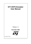
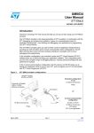
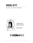
ST7SB Socket Board
User Guide
Release 1.1.1
November 2004
Ref: DOC-MDT0005
INSTRUCTIONS FOR USE—WARNING
This product is conform to the 89/336/EEC Directive. It complies with the ITE EN55022 standard for
EMC emissions and generic 50082-1 (1992 edition) immunity standards.
This product is an FCC Class-A apparatus. In a residential environment, it may cause
radioelectrical disturbances.
In addition, this programming board is not contained in an outer casing; consequently, it cannot be
immune against electrostatic discharges (ESD). It should therefore be handled only in static safe
working areas. Please refer to Appendix A Safety Requirements on page 9 for relevant safety
information
USE IN LIFE SUPPORT DEVICES OR SYSTEMS MUST BE EXPRESSLY AUTHORIZED.
STMicroelectronics PRODUCTS ARE NOT AUTHORIZED FOR USE AS CRITICAL COMPONENTS IN
LIFE SUPPORT DEVICES OR SYSTEMS WITHOUT THE EXPRESS WRITTEN APPROVAL OF
STMicroelectronics. As used herein:
1. Life support devices or systems are those
which (a) are intended for surgical implant into
the body, or (b) support or sustain life, and whose
failure to perform, when properly used in
accordance with instructions for use provided
with the product, can be reasonably expected to
result in significant injury to the user.
2. A critical component is any component of a life
support device or system whose failure to
perform can reasonably be expected to cause the
failure of the life support device or system, or to
affect its safety or effectiveness.
Table of Contents
Chapter 1:
1.1
Introduction . . . . . . . . . . . . . . . . . . . . . . . . . . . . . . . . . . . . . . . . . . 2
About the user manuals... ............................................................................. 3
Chapter 2:
Delivery Check List . . . . . . . . . . . . . . . . . . . . . . . . . . . . . . . . . . . . 4
Chapter 3:
Configuring and Connecting to Your Socket Board . . . . . . . . . . 5
3.1
3.2
Configure the power supply for your ST7 ..................................................... 5
Connect to the socket board ......................................................................... 7
Appendix A: Safety Requirements . . . . . . . . . . . . . . . . . . . . . . . . . . . . . . . . . . . 9
Product Support . . . . . . . . . . . . . . . . . . . . . . . . . . . . . . . . . . . . . . . . . . . . . . . . . 10
Software updates ...................................................................................................... 10
Hardware spare parts ............................................................................................... 10
Contact List ............................................................................................................... 11
1/12
1 - Introduction
1
ST7SB Socket Board User Guide
INTRODUCTION
The ST7SB socket board complements any ST7 programming tool that is
equipped for in-circuit programming (ICP) via a 10-pin ICC cable. For these
programming tools and emulators, the socket board provides the sockets required
to program ST7 FLASH microcontrollers without having to install them on an
application board.
Status LEDs
ICC connector
(HE10 type)
Power supply
connector
Figure 1: Typical ST7SBxx socket board
Your socket board uses your programming tool ’s ICC connection and connects via
the ICC cable (See Section 3.2.1). The programming tool, then serves as the
hardware interface with your host PC running ST7 Visual Programmer (STVP7).
When using the ST7-STICK, users have the additional possibility of connecting
their socket board directly to the ST7-STICK using the female HE10-connector on
the bottom of the socket board (See Section 3.2.2).
ST7SBxx socket boards are each designed to support the programming of a family
of ST7 microcontrollers (a typical example is shown in Figure 1). For this reason,
the layout of each type of socket board varies depending on the types of
programming sockets required to support a microcontroller family. However, the
general configuration and connection procedures explained here, remain the same
for all socket boards.
2/12
ST7SB Socket Board User Guide
1 - Introduction
Note:
The ST7SBxx socket board is meant to program small numbers of microcontrollers (i.e.
prototypes in the development stage). For mass production programming, we recommend
using the appropriate gang, or automated programmer.
1.1
About the user manuals...
This manual will help you set up your socket board. Here you will find information
about:
•
Configuring your socket board
•
Connecting to your programming tool
•
Socket board programming features
For information about the software and additional hardware intended for use with
your socket board, refer to the following documents:
ST7 Visual Programmer on-line help – program your application to your ST7
ST7-STICK User Manual – set up instructions for your ST7-STICK
ST7-EMU3 User Manual – set up instructions for your ST7-EMU3 emulator
ST7-DVP3 User Manual – set up instructions for your ST7-DVP3 emulator
ST7xxxx Datasheet – programming information that is specific to your ST7
microcontroller
ST7-Programming Tool Descriptions – listing of ST7 programming tools and
supported devices
1.1.1
Revision history
Date
Revision
Aug 2004
1.1
Jun 2001
1.1.1
Description
• Update product ordering code to ST7SBxx socket board
• Added Table 1 – Revision history table
Table 1: STICK User Manual Revision History
3/12
2 - Delivery Check List
2
ST7SB Socket Board User Guide
DELIVERY CHECK LIST
Your ST7SBxx socket board (see Figure 1) is delivered with one power supply.
The number and types of programming sockets will vary from one version to
another depending on the available packages for the ST7 family of devices that
your socket board supports. The version of your socket board is determined by the
ordering code that you have specified.
All the connection cables you will need to connect to your PC are provided with the
programming tool that you are using to connect to your PC.
4/12
ST7SB Socket Board User Guide
3
3 - Configuring and Connecting to Your Socket Board
CONFIGURING AND CONNECTING TO YOUR SOCKET BOARD
This chapter tells you how to set up and connect to your socket board for
programming. It includes how to:
3.1
•
Configure the power supply for your ST7
•
Connect to the socket board
Configure the power supply for your ST7
Your socket board allows you to configure the power supply (VDD) for your ST7.
As standard options, you can choose between 3.3V and 5V by changing the
position of the VDD jumper. In addition, you can configure other VDD supported by
your ST7 by installing the appropriate resistors in series in the area labeled
OTHER on your socket board.
Caution:
When choosing the VDD, you must ensure that the selected voltage is supported by both your
ST7 and by the programming tool that you are using to connect the socket board to your host
PC. Refer to your ST7xxx Datasheet and the user manual for your programing board for more
information.
Configure for 3.3V or 5V
To select 3.3V or 5V, simply set the VDD jumper to the appropriate position, as
shown in Figure 2.
Figure 2: Setting the VDD jumper
5/12
3 - Configuring and Connecting to Your Socket Board
ST7SB Socket Board User Guide
Configure for other VDD
To configure your socket board to use a VDD other than 3.3V or 5V, you will have
to calculate the required serial resistance and install the necessary resistors in the
area labelled OTHER that is provided on your socket board. To do this:
1
Calculate the serial resistance for the voltage you want, using the formula:
RVDD.OTHER = (50 / VVDD.OTHER) -10
RVDD.OTHER : is the serial resistance in KΩ to be installed in the OTHER area on
the socket board.
VVDD.OTHER : is the desired VDD voltage.
Example to obtain a VVDD.OTHER of 4V:
RVDD.OTHER = (50 / 4) - 10 = 2.5 KΩ
2
Install the necessary resistors in the OTHER area on the socket board. Figure 3
shows one possible solution for the example in Step 1.
3
Set the VDD jumper to the OTHER position (see Figure 2).
Figure 3: Installing serial resistors
6/12
ST7SB Socket Board User Guide
3.2
3 - Configuring and Connecting to Your Socket Board
Connect to the socket board
All ST7 programming tools that use a 10-pin ICC cable (including the ST7-STICK)
can be connected to the HE-10 type ICC connector on top of your socket board.
However, when using the ST7-STICK you can also connect via the Female HE10
connector on the bottom of your Socket board.
The following sections tell you how to setup your socket board when:
3.2.1
•
Connecting via the ICC cable (all programmers and emulators)
•
Connecting via the female HE10 connector (ST7-STICK only)
Connecting via the ICC cable
To connect to your socket board via ICC cable:
1
Plug the ICC cable into the HE-10 connectors on your programming tool and
your socket board. The ICC cable is provided with your programming tool .
2
Set both POWER jumpers to the 2 position, as shown in Figure 4, inset B .
A
B
Figure 4: Power supply jumper positions
3
Connect the power supply for both the socket board and the programming tool.
Once connected, the green Power LED should light up and remain lit.
You are ready to program your ST7 from the STVP7 interface on your host PC.
7/12
3 - Configuring and Connecting to Your Socket Board
3.2.2
ST7SB Socket Board User Guide
Connecting via the female HE10 connector
When using this connection, power for the socket board can be provided by its
power supply, or by your ST7-STICK. However, you must configure the POWER
jumpers appropriately.
Note:
No matter which option you choose for powering your socket board, your ST7-STICK’s power
supply must be connected, as it cannot be powered by the socket board.
To connect to the female HE10 connector on your socket board:
1
Plug the male HE10 connector on the ST7-STICK, into the female HE10
connector on the bottom of your socket board.
The male HE10 connector on the
top side of your ST7-STICK...
...connects to the female
connector on the bottom of
your ST7SB socket board.
Figure 5: Male and female HE10 connector
2
3
Choose a power supply configuration (i.e. both tools powered by the ST7STICK, or each tool powered by its own power supply) and set the POWER
jumpers on your socket board to the appropriate position:
-
Set POWER to 1 if the socket board is supplied by the ST7-STICK, as
shown in Figure 4, inset A.
-
Set POWER to 2 if the socket board is supplied by its own power supply as
shown in Figure 4, inset B.
Plug in the appropriate power supply, or power supplies. Once connected, the
green Power LED should light up and remain lit.
You are ready to program your ST7 from the STVP7 interface on your host PC.
8/12
ST7SB Socket Board User Guide
Appendix A Safety Requirements
APPENDIX A SAFETY REQUIREMENTS
•
Any tester, equipment, or tool used at any production step, or for any
manipulation of semiconductor devices, have its shield connected to ground.
•
The product must be placed on a conductive table top, made of steel or clean
aluminum, or covered by an antistatic surface (superficial resistivity equal to or
higher than 0.5 MΩ/cm2), grounded through a ground cable (conductive cable
from protected equipment to ground isolated with a 1 MΩ resistor placed in
series). All manipulation of finished goods must be done at such a grounded
worktable.
•
The worktable free of all non-antistatic plastic objects.
•
An antistatic floor covering grounded through a conductive ground cable (with
serial resistor between 0.9 and 1.5 MΩ) should be used.
•
It is recommended that you wear an antistatic wrist or ankle strap, connected to
the antistatic floor covering or to the grounded equipment.
•
If no antistatic wrist or ankle strap is worn, before each manipulation of the
powered-on tool, you touch the surface of the grounded worktable.
•
It is recommended that antistatic gloves or finger coats be worn.
•
It is recommended that nylon clothing be avoided while performing any
manipulation of parts.
9/12
Product Support
ST7SB Socket Board User Guide
PRODUCT SUPPORT
If you experience any problems with this product, contact the distributor or the
STMicroelectronics sales office where you purchased the product. Phone numbers
for major sales regions are provided in the Contact List, below.
In addition, at our Internet site www.st.com/mcu, you will find a complete listing of
ST sales offices and distributors, as well as documentation, software downloads
and user discussion groups to help you answer questions and stay up to date with
our latest product developments.
Software updates
All our latest software and related documentation are available for download from
the ST Internet site, www.st.com/mcu.
Hardware spare parts
Your development tool comes with the hardware you need to set it up, connect it to
your PC and connect to your application. However, some components can be
bought separately if you need additional ones. You can order extra components,
such as sockets and adapters, from STMicroelectronics, from the component
manufacturer or from a distributor.
To help you find what you need, a listing of accessories for ST development tools
is available on the ST internet site, www.st.com/mcu.
10/12
ST7SB Socket Board User Guide
Product Support
Contact List
North America
Canada and East Coast
Mid West
STMicroelectronics
Lexington Corporate Center
10 Maguire Road, Building 1, 3rd floor
Lexington, MA 02421
Phone: (781) 402-2650
STMicroelectronics
1300 East Woodfield Road, Suite 410
Schaumburg, IL 60173
Phone: (847) 585-3000
West coast
STMicroelectronics, Inc.
1060 E. Brokaw Road
San Jose, CA 95131
Phone: (408) 452-8585
Note:
For American and Canadian customers seeking technical support the US/
Canada is split in 3 territories. According to your area, contact the appropriate
sales office from the list above and ask to be transferred to an 8-bit
microcontroller Field Applications Engineer.
Europe
France +33 (0)1 47 40 75 75
Germany +49 89 46 00 60
U.K. +44 162 889 0800
Asia/Pacific Region
Japan +81 3 3280 4120
Hong-Kong +85 2 2861 5700
Sydney +61 2 9580 3811
Taipei +88 6 2 2378 8088
11/12
Information furnished is believed to be accurate and reliable. However, STMicroelectronics assumes no responsibility for the
consequences of use of such information nor for any infringement of patents or other rights of third parties which may result from its use.
No license is granted by implication or otherwise under any patent or patent rights of STMicroelectronics. Specifications mentioned in this
publication are subject to change without notice. This publication supersedes and replaces all information previously supplied.
1
STMicroelectronics
products are not authorized for use as critical components in life support devices or systems without the express written
approval of STMicroelectronics.
2
The ST logo is a registered trademark of STMicroelectronics
©2004 STMicroelectronics - All Rights Reserved.
Purchase of I2C Components by STMicroelectronics conveys a license under the Philips I2C Patent. Rights to use these components in an
I2C system is granted provided that the system conforms to the I2C Standard Specification as defined by Philips.
STMicroelectronics Group of Companies
Australia - Belgium - Brazil - Canada - China - Czech Republic - Finland - France - Germany - Hong Kong - India - Israel - Italy - Japan Malaysia - Malta - Morocco - Singapore - Spain - Sweden - Switzerland - United Kingdom - United States of America
www.st.com
12