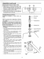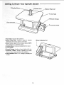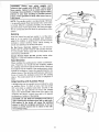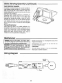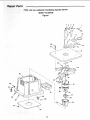
1
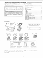
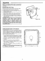
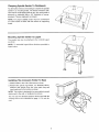
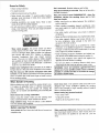
For Future Reference
MODEL NO.
113.225705
Serial
Number
Model
and
serial
numbers
may be found on the back side
of the base.
You should record both model
and serial number in a safe
place for future use.
®
OSCILLATI
DLE S,
, assembly
• operating
• repair parts
FOR YOUR
SAFETY
READ ALL
iNSTRUCTIONS
CAREFULLY
....
J
Sears, Roebuck and Co., Hoffman
Part No. SP6031
Estates,
IL. 60179
U.S.A.
FULL ONE YEAR WARRANW
e Sander:fails
ON CRAFTSMAN
dueto
a defect in material
BENCHTOP
TOOLS
or workmanship
within one year
fi_omthe date of purchase, RETURN IT TOTHE NEAREST SEARS SERVICE CENTER IN THE UNITED
!STATES_ Iand Sears will repair it, free of charge::
-_ if this Oscillating Spindle Sander is used for commercial or rental purposes, this warranty will apply
for ninety days from the date of purchase.
This warranty applies only while this product is in the United States.
This warranty gives you specific legal rights, and you may also have other rights which vary from
state to state.
=
Sears, Roebuck and Co., I)/817 WA Hoffman Estates, IL 60179
Safety Instructions
For Oscillating Spindle Sander
.....
Safety is a combination of common sense, staying alert and knowing how your oscillating spindle sander works. Read
this manual to understand this sander,
Safety Signal
Words
WARNING: means if the safety information is not followed someone could be seriously injured or killed,
DANGER:means
if the safety information is not followed
someone will be seriously injured or killed.
CAUTION: means if the safety information is not followed
someone may be injured.
..............
J
-
Before Using The Sander
i
....
!
/
WARNING: To avoid mistakes that could cause !
serious, permanent injury, do not plug the sander
in until the following steps are completed.
1
• Assembly. (See pages 8-1 1)
° Learn the use and function
(See page 13)
of the ON-OFF switch,
[J
1; Read manual before using sander.
:
Wear_afety
=
:
,:::
i : :
=
::: ::
JI
[
o Review and understanding of all safety instructions
and operating procedures in this manual.
-Review of the maintenance methods for this sander.
(See page 18)
Read the following WARNING label found on the front of
the sander:
L
lI=lt_
5. Use the proper spacer ring insert for each sleeve to minimize pinch
points between sleeve and spacer ring insert.
6. Always support workpiece against the table.
7. Avoid fire, clean out all sawdust and disconnect
i::: ,
....... :
: ::3! Weara dust masl(_ :i::
: : ::
::
:4. Keep fingers away from abrasive s[beve:when machine is on.
from any vacuum before sanding metals.
i:
,, ,,,
li .....
;, ,,,,;..........
.
, ,,,uu
I
I II
i iii1,1
,1_
i
i
.. .......................
When Installing
Or Moving
,,,,,,,,
,,,,,,,..,,
nil
.........
_,,,i
,, ,, ,,,,, ,,,,,,,,,,
The Sander
Avoid dangerous environment. Use the sander in a
dry, indoor place protected from rain. Keep work area
well Fighted.
To avoid burns or other fire damage, never use the
sander near flammable liquids, vapors or gasses.
To avoid injury or death from electrical shock:
° Ground the sander. This sander has an approved 3conductor cord and a 3-prong grounding type plug.
Use only 3_wire, grounded outlets rated 120 volts, 15
amperes (amps), The green conductor in the cord is
........ the grounding wire, To avoid electrocution, Never con.... nect the green wire to .a live terminal.
::: i :"Make sure your fingers do not touch the plug's metal
:::: : ::
plugging or unplugging the sander.
!
,,,,1.111
I
o Never use this or any power sander for wet sanding.
Doing so could cause electrocution, serious injury or
worse.
To avoid injury from unexpected sander movement:
- Always unplug the sander before, moving it.
o Put the sander on a firm level surface where there is
plenty of room for handling and properly supporting the
workpiece.
Attach rubber feet.
::
o Support the sander so it does not rock: ......
- Bolt the sander to its work surface. Use the fasteners
and method shown in "Assembly." (See page 9.)
o Never stand on too!. Serious injury could occur #the
tool tips. Do not store anything above or near the too]
where anyone might stand on the tool to reach it.
Before Each Use
* alignment of moving parts,
Maintain tools with care: Keep the sander clean for
maximum and safest performance.
o binding ol moving parts,
Remove wrenches
o broken or damaged parts,
To avoid injury from jams, slips or thrown
Lnspect your sander. Check for:
o loose spindle washer and nut,
° stable mounting, and
that may affect the way the
o Use the correct spacer ring insert. The opening
between the sanding sleeve and insert must be 1/8th
of an inch or less. (See page 11)
If any part is missing, bent, or broken in any way, or any
_=lectrical parts don't work properly, turn the sander off
and unplug the sander. Replace damaged, missing, or
Failed parts before using the sander again.
• All sanding drums, washers and nuts are tight. No
parts should have excessive play prior to operating
unit.
Disconnect the sander to avoid injury from accidental
starting. Turn switch off, unplug sander and remove the
switch key before changing the setup or sanding drum.
i
jill
IllllllllHIIll
I
I
I
IIIJIIql
I
iiiii!
o Keep work area clean. Cluttered work surfaces invite
accidents. Floor must be clean and dry for stabte footing.
[
iiiiiiii!1
Plan Ahead To Protect Your Eyes, Hands,
Ill
I
II
II
U
. Do not layout, assemble, or setup work on the sander
while any parts are moving.
• Avoid accidental starting. Make sure switch is "OFF"
before plugging sander into a power outlet.
Use the right tool. Don't force tool or attachment to do a
job it was not designed to do.
u,i, ,hi,,
IBJl
To avoid injury from accidental contact with moving
parts:
Plan your work. Think through how you will hold and
maneuver the workpiece against the sanding drum.
,i
I
Face and Ears
Know your sander. Read and understand the owner's
manual and labels affixed to the tool. Learn its application
and limitations as well as the specific potential hazards.
ill
pieces:
• Use only recommended
accessories.
Consult this
owner's manual for recommended accessories. The
use of improper accessories may cause injury. (See
page 19).
o worn or damaged electric cords,
o any other conditions
sander works.
from tool before turning on.
................
I_p_ I ,I
Dress for Safety
inspect your workpiece. Make sure there are no nails
or foreign objects in the part of the workpiece to be
sanded.
• Wear nonstip footwear.
° Tie back long hair.
• Roll long sleeves above the elbow.
° Noise levels vary widely. To avoid possible hearing
damage, wear ear plugs or muffs when using sander
for hours at a time.
Plan the way you will hold the workpiece from start
to finish. Avoid awkward operations and hand positions
where a sudden slip could cause finger or hand to move
into a sanding surface.
• Sanding operations are usually dusty. Wear a dust
mask along with the safety goggles.
Don't overreach.
° Do not wear loose clothing, gloves, neckties or jewelry
(rings, wrist watches), They can get caught and draw
you into moving parts.
WEAR
Maintain balance and footing.
Keep face and body to one side. Stay out of line with a
possible throwback.
Plan your work to avoid THROWBACKS - when the
workpiece catches the sanding drum and is torn
from your hands:
o Make sure there's no debris between the workpiece
and its supports.
YOUR
-When sanding irregularly shaped workpieces, plan
your work support so it will not slip and be pulled from
your hands,
° Use extra caution with large, very small or awkward
workpieces.
o Never use this tool to finish pieces too small to hold by hand.
° Wear safety goggles. Any power sander can throw
foreign objects into the eyes. This can cause permanent eye damage. Wear safety goggles (not glasses)
that comply with ANSI Z87.1 (shown on package).
Everyday eyeglasses have only impact resistant
lenses. They are not safety glasses. Safety goggles
are available at Sears retail catalog stores. Glasses or
goggles not in compliance with ANS! Z87.1 could serf
ously hurt you when they break.
• Use extra supports (tables, saw horses_ blocks, etc.l
for any workpieces large enough to tip when not
secured to the work surface,
3
When Sanderis
Running
Befo[e starting your :work, watch the sander while it runs.
If it:i makes;: an! dnfamiiiar: noise o:r vibrates excessively,
: stop i
the sander
off. Unp!_g the
: sander. Do not restart until identifying
and co rrecting the
Don't
force
tool.
It will
perform
better
and safer
designed
rate. Press
workpiece
against
the
sleeve hard enough to begin
sanding without
at its
sanding
bogging
down or binding spindle.
Before freeing
any jammed
material:
•Tum switch "OFF".
....Before Using thesander; make sure the sanding drum
turns Counterclockwise, when viewed from above.
• Unplug the sander.
• Wait for all moving parts to stop.
Keepcttiidrenaway.
Keep' all visitors a safe distance
from the sander and workpiece.
;,i,i_i,,,
,',,,,_ _
.......................
Before
Illll
Leaving The Sander
Turn switch off. Don't leave tool until the unit comes to a
complete stop:
:
i.
i:i
IL II
I,
I
II
Illllllll
Illl
I IIlll
,l!l ,I,I
II
Make workshop child-proof. Remove the yellow switch
key. Disconnect master switches. Store it away from children and others not qualified to use the tool. Lock the
shop.
....
Precautions
To Take
When sanding metals, sparks
cause a fire. To avoid this:
1. Disconnect any dust collecting
Precautions
or
When Sanding
hot
hose
fragments
could
lead poisoning.
It is also difficult to identify whether or not a paint contains lead. Therefore, we recommend
the following precautions when sanding all paints:
4. Protect
1. Protect your lungs. Wear a dust mask or respirator at
al! times. Wear only dust masks that are suitable for
working in lead paint sanding environments.
Ordinary
painting masks do not offer this protection.
5. Thoroughly
ii
i
i,u
the
environment
when
sanding
paint.
Use a
dust collection
system
if possible. Seal the work area
with plastic if necessary.
Do not track paint dust outside the work area.
clean the work area upon completion
of
paint sanding project.
It project lasts for an extended
period of time, clean work area often. Items such as
sanding dust, vacuum filter bags, plastic drop cloths, etc.
should be placed in a sealed container and disposed of
properly. Clean al! items exposed to sanding dust.
2. Do not allow children or pregnant women to enter the work
area until paint sanding job is complete
and work area is
paint particles: Do
area'where paint Is
i
--
being sanded. After sanding
paint, wash and clean up
before eating, drinking
or smoking. Do not leave food,
drinl_s, or tobacco products
in the work area where
dust can settle on them.
Sanding of lead based paint is not recommended. It is
difficult to control the contaminated dust that could cause
•
dust from inside the unit
3. Remove all traces of metal dust from inside the unit
before sanding wood again.
When Sanding Paint
clean.
:,
To prevent ingesting contaminated
i:::_::_ii
not eat;_i:i:
drink; 1:0t:_smoke in a:work:
......
2. Remove all traces of wood
before sanding metals.
from the sander.
ToTake
Metals
4
Motor
General
Specifications
Electrical
and Electrical
Requirements
..............
Connections
DANGER: To avoid electrocution:
WARNING
1. Use only identical replacement parts when ser-
minals of plug when
installing
plug to or from the outlet.
vicing. Servicing should be performed
qualified service technician.
by a
This too] is intended for indoor residential
only.
I!,ln
and Motor
.
fingers
If power cord is worn or cut,
have it replaced immediately-
2. Do not use in rain or where floor is wet.
Power Supply
Do not permit
"1
Ul
to touch
or
the ter-
removing
or damaged
the
in any way,
use
I,,
I I
Specifications
WARNING: To avoid electrical hazards, fire hazards or damage to the tool, use proper circuit protection. Your tool is wired at the factory for
operation using the voltage shown. Connect tool
to a power line with the appropriate voltage and a
15-amp branch circuit. To avoid shock or fire, if
power cord is worn or cut, or damaged in any way,
have it replaced immediately.
The A-C motor
used on this tool is a relay start, having the
following specifications:
',It is wired at the factory for operation on 11Oq20V AC. 60 Hz. operation.
1/3
JJ_Z
110-120
_e
(Cycles) 6
Counterclockwise
110-120
V01t, 60 Hz. Tool information
NOTE: The plug supplied on your tool may not fit into the
outlet you are planning to use, Your local electrical code
may require
slightly different
power cord plug connections. If these differences
exist refer to and make the
proper adjustments
per your local code
is plugged in and turned on.
before
your tool
In the event of a malfunction
or breakdown,
grounding
provides a path of least resistance for electric current to
reduce the risk of electric shock. This tool is equipped
with an electric cord having an equipment grounding conductor and a grounding
plug, as shown, The plug must
be plugged
into a matching
outlet that is properly
installed and grounded in accordance w_th all local codes
and ordinances.
Do not modify the plug provided. If it will not fit the outlet,
have the proper outlet installed by a qualified electrician.
A temporary adapter may be used to connect this plug to
a 2-pole outlet, as shown, if a properly grounded outlet is
not available.
This temporary
adapter should be used
only until a properly grounded outlet can be installed by a
qualified electrician,
The green colored rigid ear, lug and
the like, extension from the adapter must be connected to
a permanent
box.
ground
such as a properly
grounded
outlet
If the grounding instructions
are not completely understood, or if you are in doubt as to whether the Iool is properly grounded check with a qualified electrician or service
personnel.
WARNING: if no_ properly grounded, this tool can
cause an electrical shock, particularly when used
in damp locations, in proximity to plumbing, or out
of doors. If an electrical shock occurs there is the
potential of a secondary
hazard, such as your
hands contacting the sanding drum.
3-Prong Plug
Properly
Grounded
Outlet
_,
Grounding
Prong
Green
Grounding
3-Prong
P,ug
I
Lug
_:_1
!(_-_
Make sure this
is Connected
to a Known
Ground
Improper connection
of the equipment
grounding
conductor could result in a risk of electric shock. The conductor with insulation having an outer surface that is green
with or without yellow stripes is the equipment grounding
conductor.
If repair or replacement
of the electric cord or
plug is necessary,
do not connect
ing conductor to a live terminal
the equipment_g
Adapter
roundNOTE: The adapter illustrated
is for use only if you have a
properly grounded 2-pro,qg outlet,
Motor Specifications and E/ectrical Requirements
4. Fuses may "blow" or circuit breakers may trip frequently if:
a: Motor Is Overloaded-Overloading
can occur if you
sand too rapidly or make too many staWstops in a
short time.
Motor Safety Protecti on
IMPORTANT: Tb avoidmotor
(continued)
damage; this motor should
be _blown' Out: Or vacuumed: frequently to keep sawdust
from interfering with normal motor ventilation.
1.Connect this tool to a power source with the appropriate voltage for your model and a 15-amp branch circuit
with a 15-amp time delay fuse or circuit breaker. Using
the wrong size fuse can damage the motor.
b. Line voltages should not be more than 10% above
or below the nameplate voltage. For heavy loads,
however, the voltage at motor terminals must equal
the voltage specified for your model.
5. Most motor troubles may be traced to loose or incorrect
connections, overload, low voltage (such as small size
wire in the supply circuit) or to overly long supply circuit
wire. Always check the connections, the load and supply circuit whenever motor doesn't work well. Check
wire sizes and extension cord length with the Wire Size
Chart.
2, If the motor won't start, turn off the power switch immed ately:and unplug the toot. Check the spindle to make
sure it turns freely. If the spindle is free, try to start the
motor again, If the motor stiU does not start, refer to the
"Motor Troubleshooting Chart.'
3. tf the motor suddenly stalls while sanding, turn off the
power switch, unplug the tool, and free the spindle
from the workpiece. The motor may now be restarted.
Wire Sizes
NOTE: Make sure the proper extension cord is used and
is in good condition.
The use of any extension cord will cause loss of power. To
keep this to a minimum and to prevent overheating and
motor bum-out, use the table shown to determine the minimum wire size (A.W.G.) extension cord.
Extension
Cord Length
t10-120V
0-25 Ft.
26-50 Ft.
Use only 3-wire extension cords with 3-prong grounding
type plugs and 3-pole receptacles.
Contents
i
Warranty ........................................................................
2
Safety Instructions For Oscillating Spindle Sander ....... 2
Safety Signal Words. ................................................... 2
Before Using The Sander ........................................... 2
When Installing Or Moving The Sander ..................... 2
Before Each Use ........................................................
3
Plan Ahead To Protect Your Eyes, Hands, Face and Ears 3
Dress for Safety. .........................................................
3
When Sander is Running ........................................... 4
Before Leaving The Sander ....................................... 4
Precautions To Take When Sanding Metals ................. 4
Precautions To Take When Sanding Paint .................... 4
Motor Specifications and Electrical Requirements ........ 5
General Electrical Connections .................................. 5
Power Supply and Motor Specifications ..................... 5
110-120 Volt, 60 Hz. Tool Information ........................ 5
Motor Safety Protection ..............................................
6
Wire Sizes ..................................................................
6
Contents ........................................................................
6
Unpacking and Checking Contents ............................... 7
List of Loose Parts .......................................................
7
Loose Parts ................................................................
7
:i: i Assembly ..: ....................................................
8
i: i iBoiting Spindle Sander To Workbench ...................... 8
C;amping Spindle Sander To Workbench .................. 9
Mounting Spindle Sander to Legset ........................... 9
installing The ACcessory: Holder To Base .................. 9
Attaching the ACcesso_ Holder to Wa I .........
10
....
: Changing Sleeves and [)rums .................................. 10
?: :
!,
:ii
:i<i
•
•
.......
Wire Sizes Required
for (A.W.G.)
i
uu
iii iiii
16
14
i
i
i
ul
Selection OI Spacer Ring Inserts And Upper Spindle
Washers ..................................................................
Getting to Know Your Spindle Sander .........................
On-Off Switch ...........................................................
Safety Instructions for Oscillating Spindle Sander ......
Before Using The Sander .........................................
When Installing Or Moving The Sander ...................
Before Each Use ......................................................
Ptan Ahead To Protect Your Eyes, Hands, Face and Ears
Dress for Safety .......................................................
When Sander is Running .........................................
Before Leaving The Sander .....................................
Precautions To Take When Sanding Metals ...............
Precautions To Take When Sanding Paint .................
Basic Sanding Operation .............................................
Sanding Sleeve Selection ........................................
Sanding ....................................................................
Feed Direction ..........................................................
Edge Sanding with Auxiliary Fence ..........................
Dust Collection Capability ........................................
Transporting Sander ................................................
Maintenance ................................................................
Lubrication ................................................................
Wiring Diagram ............................................................
Sears Recommends The Following Accessories ........
Troubleshooting ...........................................................
Notes ...........................................................................
Repair Parts ................................................................
11
12
13
14
14
14
!4
14
15
15
15
16
16
16
16
17
17
17
18
18
!8
18
18
19
20
21
22
Unpacking and Checking Contents
1, Remove tooi from carton by lifting unit,
List of Loose Parts
2. Place the tool on a secure, stationary work surface and
took the tool over carefully.
A
B
C
D
E
F
WARNING: For your own safety, never connect
plug to power source outlet, or insert switch key
until all assembly steps are complete and until you
have read and understood the entire owners manual.
WARNING: To avoid injury, if any parts are missing, do not attempt to assemble the spindle sander,
plug in the power cord, or turn the switch on until
the missing parts are obtained and installed correctly.
G
Oscillating Spindle Sander .......................................
Owners Manual ........................................................
Holder Accessory .....................................................
Drum Sandpaper 1/2" reed .......................................
Wrench .....................................................................
Spacer Ring inserts
1"1.D.........................................................................
1-3/8" LD.................................................................
1-7/8" I.D..................................................................
2-3/8" I.D. (Installed .................................................
3-3/8" I.D..................................................................
Bag of Loose Parts
Containing the fo]towlng parts:
Rubber feet ...............................................................
Washer, Flat 21/64 x 7/8 x 3/64 ...............................
Washer, Flat 21/64 x 5/8 x 1/32 ...............................
Switch Key ................................................................
Loose Parts
F
A
/_//
1" Inside
Diameter
1-318" Inside
D iameter
1-7/8" Inside
Diameter
3-3/8" Inside
Diameter
Spacer Ring
Insert (1)
Spacer Ring
Insert (1)
Spacer Ring
Insert (1)
Spacer Ring
Insert (1)
©
21164×718x3164
Washer (1)
NOTE: The spindle
ter drum, sanding
insert installed.
sander
sleeve
4#
©
21164xSISx1132
Washer (1)
is shipped with a 2" 1.D. diameand a 2-3/8" I.D. spacer ring
Switch Key (1)
NOTE:
Rubber Feet (4)
Parts are not shown to actuai
size.
1
1
1
1
!
1
1
t
1
!
4
1
1
1
CAUTION: To avoid injury from tool movement,
supporting surface
where spindle sander is
mounted
should be examined carefully
after
mounting to insure no movement during use can
result_ If any tipping or walking is noticed, secure
to workbench or supporting surface before operating spindle sander.
Bolting Spindle
Rubber Feet
Sander To.Workbench
If Spindle sander isto be used in a permanent location, it
should be fastened securely to a firm supporting surface
such as a workbench. If mounting to a workbench, holes
should be drilled through supporting surface of the workbench using dimensions as shown.
1. The unit should be bolted securely using 1/4" screws,
washers and hex nuts (not included). Screw length
should be 1-1/2" plus the thickness of thebench top.
, Locate
and mark the holes where sander is to be
mounted.
3. Drill (4) 3/8" diameter holes through workbench,
11-t/2"
O
Front
1
4. Place sander on workbench, aligning holes on base
with holes drilled in workbench.
5. Insert (4) 1/4" diameter
attach nuts securely.
screws
and washers
lf4" diameter
and nuts.
I CAUTION:
To screws
avoid injury
from tool movement,
•
and
1__
use
1
8
-IT
fl
l!
17-1t8"
•
Clamping
Spindle Sander
To Workbench
An alternative method of mounting is to fasten the spindle
sander to a mounting board. The board should be sufficient size to avoid tipping while in use. Any good grade of
plywood or chipboard with a 3/4" thickness is recommended. (Thinner chipboard can break.)
NOTE: For proper stability, holes must be countersunk
so screw heads are flush with the surface of supporting
board.
Mounting
Spindle
Sander
to Legset
The sander may also be attached to the 9-22243 tegset
as shown.
NOTE: To assemble legset follow directions provided in
legset carton.
Installing
The Accessory
Holder
To Base
1. Attach holder to the side of the base as shown.
2. Remove the spacer ring inserts, 1/2" diameter sleeve,
washers and wrench from the loose parts bag and
insert each part in the holder as shown.
NOTE: This holder is designed to be removable to permit
attachment to the wall, or workbench as shown.
The 7/8" and 5/8" diameter washers wilt be used with the
sanding sleeve sizes identified on page 11. Do not discard.
ASsembly(continued)
usingthe dimensions in the figure. Screw them in until
there is al/i6
gap between the Screws and the wall.
.....
If secUring to drywall or plaster, toggle bolts will be
:
: :required to adequately support the holder.
:2, Slide the slots in the back of the accessory holder over
the. sCrew heads. If the holder is not snug against the
wall, adjust the screws as necessary.
._. 1_314,,-,.-
ii i
(;hanging
Removal
drums.
Sleeves
and
and Drums
installation
of
sander
sleeves
and
(_--,_-_-
NOTE: The spindle sander is shipped with a 2" diameter
drum, sanding sleeve, and a 2-3/8" diameter spacer ring
insert installed.
5t16-24
Sanding
: : Washer
__
WARNING:
To avoid injury from accidental
starting, always turn switch "OFF"
and remove switch
key before removing
or replacing
the spacer ring
inserts, sleeves and drums.
Changing
and installing
1/2" diameter.
sanding
sleeves
larger
Sanding
(_-----_
as shown.
2. plied
Remove
the hex nut, upper
__%
sleeve,
spacer
ring insert,
Sleeve
Drum
than
t. Hand support sleeve and rubber drum on spindle while
loosening the 5/16-24" hex nut using the wrench .supspindle washer,
Nut
sanding
Spacer
_
Lower
Ring Insert
Spindle
and rubber sleeve.
3. Remove the lower spindle
from around the spindle,
washer
and clean
sawdust
NOTE: This cleaning
is highly recommended
whenever a wet!dry vac is not connected
to the dust collection port and used with sander. A dust buildup may
cause the oscillating
motion to stop when the sawdust
port is blocked.
4. Slide the lower spindle
washer
(grooved
side down).
The lower
used with all drums and sleeves.
5, Position spacer ring insert
recommended
spacer ring
table on page 1 1).
onto the spindle
spindle washer
is
in the table recess. (See
insert selection
area from
SANOING
SLEEVE
6. Place desired
sanding
sleeve on correct drum and
slide them on the spindle. NOTE: It the drum is difficult
to slide over the spindle, apply talcum powder to the
spindle.
7. Install the correct
upper
spindle
washer
nut and tighten the hex nut with wrench
the sleeve. Do not overtighten.
8.
Remove the wrench
on the holder.
and return
9. Plug line cord in the power
source
SPAC ER
R| NG
OPENING
and 5/1 6-24"
while
grasping
it to the storage
area
and install the key.
SPACER:
RING
10
TO
LOOSEN
WARNING:
To avoid injury from accidental start-
ing, always turn switch "OFF", unplug the sander
and remove switch key before removing or replacing the spacer ring inserts, sleeves and drums.
Changing and installing sanding sleeves for the 1t2"
diameter sanding drum:
1. Hand support sleeve and rubber drum on the spindle
and loosen 5/16-24" hex nut using the wrench supplied
as shown.
2, Remove the hex nut, upper spindle washer,
sleeve, spacer ring insert, and rubber sleeve,
3. Remove
the lower spindle
from around
the sawdust
washer
sanding
_
_it
and clean sawdust
4, Slide the lower spindle washer
side down), The lower spindle
drums and sleeves.
5. Position 1" opening
table recess.
diameter
6. Locate
sleeve
1/2" sanding
--.,-_
_.._.
onto the shaft (grooved
washer is used with all
spacer
ring insert in the
in the power
Selection
Of Spacer
Spindle Washers
it to the storage
Sleeve
I,D, Spacer
Ring
ower
Spindle
/
and slide it on the spindle.
and return
Sanding
_Washer
7. Install the upper spindle washer and 5/16-24" hex nut
and tighten the hex nut with wrench while holding the
sleeve. Do not overtighten.
9, Plug the line cord
key.
O.D. Washer
1/2"
_1"
is used.)
8. Remove the wrench
on the holder,
"'--_----518"
Nut
port,
NOTE: This cleaning
is highly
recommended
whenever a wet/dry vac is not connected
to the dust coftection port and used with sander.
A dust buildup may
cause the oscillating motion to stop when the sawdust
port is blocked,
(No drum
5/16-24
area
source and install the
Ring Inserts
And Upper
WARNING:
Using the wrong spacer ring insert may
permit
small
pieces
of wood
or finger
tips to
become
wedged between
the abrasive surface and
the metal ring.
Sanding Sleeve
Outside Diameter
Spacer Ring insert
Opening Inside Diameter
Upper Spindle Washer Size
t/2 Inch
1 Inch
5/8 Inch Outside
Diameter
3/4 Inch
1 Inch
5/8 Inch Outside
Diameter
1 Inch
1-3/8 Inch
7/8 Inch Outside
Diameter
1-1/2 Inch
1-7/8 Inch
7/8 Inch Outside
Diameter
2 Inch
2-3/8 inch
1-3/4 Inch Outside
Diameter
3 Inch
3-3/8 Inch
1-3/4 Inch Outside
Diameter
1t
Getting!to
i
Know
Your Spindle
:
Sander
4 Sanding
3 Rubber Drum
ii
L LI L
_
2 Spacer Ring Insert
1 Work Table
6 Wrench Storage
5On,
7 Accessory Holder
1. Work Table. Supports the workpiece.
8 Dust Collection Port
2. Spacer Ring Insert. Permits a variety of abrasive
diameters to be used on various curve sizes.
3. Drum, Rubber support for the abrasive sleeve. NOTE:
Not required for 1/2" diameter sleeve.
4, Sanding Sleeve. Removes material from the wood.
5, On-Off switch_
.........
: :
6. Wrench Storage, Location of wrench when not in use.
8. Dust Collection
hookup.
Port. 2:-112''_openingfor::we_dryivaC
::
:,: : i i::i:;: :::: :i:
,i
12
[
On-Off
Switch
The On-Off switch has a locking feature. This Feature Is
Intended To Help Prevent Unauthorized And Possible
Hazardous Use By Children And Others.
1. To turn sander "ON" insert key into switch.
NOTE: Key is made of yellow plastic, located in loose
parts bag.
2. Insert finger under switch lever and Pull end of switch
out.
3. To turn sander "OFF". Push lever in.
WARNING: Never leave the sander unattended until !
it has come to a complete stop.
I
4. To lock switch in "OFF" position, hold switch "IN" with
one hand. Remove key with other hand.
WARNING: For your own safety, always lock the
switch "OFF" when sander is not in use. Remove
key and keep it in a safe place. Also, in the event of
a power failure (all of your lights go out) turn
switch off, remove the key and store it remote from
spindle sander.
, ,,,,,,,,,,,_
_,,,_,,,_
CAUTION: Before turning switch on, make sure the
drum and sleeve is properly installed.
13
tylnstructionsfor:Oscillating
i
SpindleandSander
function of
use
the
i
i
iLearn fhe
Before Usinq The Sander
-Assembly.
(See page 13)
Review:and understanding of all safety instructions
and operating procedures in this manual.
- Review of the maintenance methods for this sander.
(See page t8)
(See pages 8-11)
When Installing
or Moving
'
ON-OFF switch.
The Sander
Avoid dangerous environment. Use the sander in a
dry, indoor place protected from rain. Keep work area
well lighted.
Do=ng so could
worse.
To avoid
injury
cause
from
electrocution
unexpected
To avoid burns or other fire damage, never use the
sander near flammable liquids, vapors or gasses.
° Always
To avoid injury or death from electrical shock:
plenty of room for handling
workpiece,
* Attach rubber feet,
unplug the sander
° Put the sander
• Ground the sander_ This sander has an approved 3conductor cord and a 3-prong grounding type plug.
Use only 3-wire, grounded outlets rated 120 volts, 15
amperes (amps). The green conductor in the cord is
the grounding wire To avoid electrocution, Never connect the green wire to a live terminal.
serious
sander
before
and properly
or
movement:
moving
on a firm level surface
injury
it.
where
there
supporting
is
the
° Support the sander so it does not rock.
° Bolt the sander to its work surface. Use the fasteners
and method
shown
in "Assembly,"
(page
9)
o Never stand on tool. Serious injury could occur if the
tool tips. Do not store anything above or near the toot
where anyone might stand on the tool to reach them.
- Make sure your fingers do not touch the plug's metal
prongs when plugging or unplugging the sander.
• Never use this or any power sander for wet sanding.
Before Each Use
Remove wrenches from tool before turning on.
Inspect your sander, Check for:
To avoid injury from jams, slips or thrown
° alignment of moving pads,
° binding of moving parts,
° broken or damaged parts,
• Use only recommended
accessories.
Consult
owner's manual for recommended
accessories.
use of improper
page 19).
° loose spindle washer and nut,
• worn or damaged electric Cords,
accessories
may cause
injury.
this
The
(See
• Use the correct spacer
ring insert. The opening
between the sanding sleeve and insert must be 1/8 of
° stable mounting, and
° any other conditions
sander works:
pieces:
that may affect the way the
an inch or less. (See page 11)
• All sanding drums, washers
parts should have excessive
unit.
If any part is missing, bent, or broken in any way, or any
electrical parts don't work properly, turn the sander off
and unplug the sander. Replace damaged, missing, or
failed parts before using the sander again.
and nuts are tight. No
play prior to operating
• Keep work area clean. Cluttered work surfaces invite
accidents. Floor must be clean and dry for stable foot-
Disconnect the sander to avoid injury from accidental
starting. Turn switch off, unplug sander and remove the
switch key before changing the setup or sanding drum.
ing.
Maintain tools with care. Keep the sander clean for
maximum and safest performance.
ill
i i
Plan Ahead To Protect Your Eyes, Hands, Face and Ears
To avoid injury from accidental contact with moving
parts:
Know your sander, Read and understand the owner's
: manual and labels affixed to the tool. Learn its application
,
i and limitations as well as the specific potential hazards.
i::
Plan your work, Think through how you witl hold and
: maneuver the w0rkpiece against the sanding drum.
• Do not layout, assemble, or setup work on the sander
while any parts are moving.
° Avoid accidental starting. Make sure switch is "OFF"
before plugging sander into a power outlet.
Use the right tool. Don't force tool or attachment to do a
job itwas not designed to do.
14
Dress for Safety
* Wear nonslip footwear.
Don't overreach. Maintain balance and footing.
. Tie back long hair.
* Roll long s_eeves above the elbow.
Keep face and body to one side. Stay out of line with a
possible throwback.
o Noise levels vary widely. To avoid possible hearing
damage, wear ear plugs or muffs when using sander
for hours at a time.
Plan your work to avoid THROWBACKS - when the
workpiece catches the sanding drum and is torn
from your hands:
* Sanding operations are usually dusty. Wear a dust
mask along with the safety goggles.
• Make sure there's no debris between the workpiece
_nd its supports.
° Do not wear loose clothing, gloves, neckties or jewelry
(rings, wrist watches). They can get caught and draw
you into moving parts.
• When sanding irregularly shaped workpieces, plan
your work support so it will not slip and be pulled from
your hands.
WEAR
• Use extra caution with large, very small or awkward
workpieces.
YOUR
° Never use this tool to finish pieces too smaUto hold by hand.
• Use extra supports (tables, saw horses, blocks, etc.)
for any workpieces large enough to tip when not
secured to the work surface.
° Never use another person as a substitute for a table
extension, or as additional support for a workpiece that
is longer or wider that the basic sander table, or to help
feed, support or pull the workpiece.
• Clear everything except the workpiece and related support devices off the table before turning the sander on.
• Wear safety goggles. Any power sander can throw
foreign objects into the eyes. This can cause permanent eye damage. Wear safety goggles (not glasses)
that comply with ANSI Z87,1 (shown on package).
Everyday eyeglasses have only impact resistant
lenses. They are not safety glasses. Safety goggles
are available at Sears retail catalog stores. Glasses or
goggtes not in compliance with ANSI Z87.1 could seriously hurt you when they break,
• Always feed workpJece from right to left against the
direction the drum sleeve is rotating.
• Do not use drums or sanding sleeves which show
visual signs of wear such as grooves, tears or rips,
Inspect your workpiece make sure there are no nails or
foreign objects in the part of the workpiece to be sanded.
WARNING: Don't let familiarity
(gained from frequent use of your spindle sander) cause a careless
mistake. A careless fraction of a second is enough
to cause a severe injury.
Plan the way you will hold the workpiece from start
to finish. Avoid awkward operations and hand positions
where a sudden slip could cause finger or hand to move
into a sanding surface.
When Sander
is Running
Before starting your work, watch the sander while it runs.
If it makes an unfamiliar noise or vibrates excessively,
Stop Immediately. Turn the sander off. Unplug the
sander. Do not restart until identifying and correcting the
problem.
Never leave tool running
Don't force tool. It will perform better and safer at its
designed
rate, Press workpiece
against
the sanding
sleeve hard enough to begin sanding without bogging
down or binding spindle.
Before freeing any jammed material:
• Turn switch "OFF".
unattended.
Before using the sander, make sure the sanding drum
turns counterclockwise, when viewed from above.
• Unplug the sander.
• Wait for air moving parts to stop.
Keep children away. Keep all visitors a safe distance
from the sander and workpiece.
Before
Leaving
The Sander
Turn switch off. Don't leave toot until the unit comes to a
complete stop.
Make workshop child-proof. Remove the yellow switch
key. Disconnect master switches. Store it away from chiL
dren and others not qualified to use the tool. Lock the
shop.
15
Sanding Metals
When sandlng me_als,_ sparks or hot fragments
cause:a fire::!To av0id this:
:
:_:
:::li_Disconnect any_:duStColtectinghosefromthe
could
........
2. Remove all traces of wood dust from inside the unit
:
sandeil
before sanding metals.
&Remove all traces of metal dust from inside the unit
before sanding wood again.
Precautions To Take When Sanding Paint ....
Sanding of lead based paint is not recommended. It is
difficult to control the contaminated dust that Could cause
lead poisoning.
It is also difficult to identify whether or not a paint contains tead_Therefore, we recommend the following precautions when sanding all paints:
• ........
being sanded. After sanding paint, wash and clean up
before eating, drinking or smoking. Do not leave food,
drinks, or tobacco products in the work area where
dust car settle on them.
Protect the environment when sanding paint. Use a
dust collection system if possible. Seal the work area
with plastic if necessary. Do not track paint dust outside the work area.
4,
1. Protect your lungs, Wear a dust mask or respirator at
all times. Wear 0niy dust masks that are Suitable for
w0rking:in lead paint sanding environments. Ordinary
painting masks do not offer this protection.
,
2. Do not allow children or pregnantwomen to enter the work
area until paint sanding jobis complete and work area is
clean.
3. To prevent ingesting contaminated paint particles: Do
not eaL drink, or smoke in a work area where paint is
Thoroughly clean the work area upon completion of
paint sanding project. If project lasts for an extended
period of time, clean work area often. Items such as
sanding dust, vacuum filter bags, plastic drop cloths, etc.
should be placed in a sealed container and disposed of
properly. Clean all items exposed to sanding dust.
Basic Sanding Operation
Sanding
Sleeve
NOTE: Do Not use sander without a sanding
Doing so will damage the rubber drum.
Selection
Selecting the correct size diameter, correct size grit, and
correct type sanding sleeve is an extremely important
step in achieving a high quality sand_ed finish. Aluminum
oxide, silicon carbide, and other synth etic abrasives are
best for power sanding. Natural abrasives, such as flint
and garnet, are too soft for economical use in power
sanding.
Select and install the desired sanding sleeve for your particular application. See optional sleeves and drums.
Sanding sleeves from 1/2" to 3" can be used with this
sander. Choose one that is close in size to the workpiece
you are sanding. Also install the appropriate spacer ring
insert (page 11 ).
In general, coarse grit will:remove the most material and
finer grit will produce the best finish in all sanding operat
lions. The condition of the surface to be sanded will
determine which grit will do the job. If the surface is
rough, start with a coarse grit and sand until the surfaCe
is uniform. Medium grit may then be used to remove
scratches left by the coarser grit and finer grit used for
finishing of the surface, Always continue sanding with
each grit until surface is uniform.
ring insert with its matching sanding sleeve could
result in fingers being pinched or the workpiece
being pulledFailure
down to
between
thecorrect
spacer size
ringspacer
insert
WARNING:
use the
and sanding sleeve.
o
1"
sleeve.
1-1/2"
16
2"
3"
WARNING:
Always wear safety goggles (not
glasses) that comply with ANSI Z87.1 when using
your sander. Failure to do so could result in dust,
shavings, loose particles, or foreign ob)ects being
thrown in your eyes resulting in possible serious
injury. If the operation is dusty, also wear a face or
dust mask.
NOTE: This spindle sander is a unique design. Although
it is generally quieter than most power tools, some noise
is normal. When it is operating normally, you will hear a
gear-drive noise. As the gears wear, they may get louder.
This is normal and does not affect the performance of the
sander.
Sanding
Insert the switch key and turn sander on. Let the motor
build to its full speed, then gradually feed workpiece
against the rotation of sanding sleeve. DO NOT let the
workpiece contact sanding sleeve before turning on
sander and allowing it to develop full speed.
Do Not Force. Exercise Caution! You will become
familiar with the sander's features with practice and use.
If at all possible, always sand with a scrap piece of the
same wood, beforehand.
Atways Remain Alert! Do Not operate sander when
fatigued, or under the influence of alcohol or drugs.
Feed Direction
When sanding, the sanding sleeve rotates counterclockwise. Therefore, you should feed the workpiece against
the sanding sleeve from right to left as shown. When led
from right to left, the rotation of the sanding sleeve sands
against the workpiece. If fed in the opposite direction, the
rotation forces of the spinning sanding sleeve will tend to
throw or bounce the workpiece away from the sanding
sleeve. This could cause loss of control of workpiece or
injury.
Edge Sanding
with Auxiliary
Fence
A straight edge can be sanded more accurately by using
an auxiliary fence. To attach a fence, turn the sander
OFF and clamp a suitable wood piece securely to the
table. Adjust the gap between the fence and sanding
drum to the desired width. Stand clear of the path of the
workpiece and feed it in slowly from right '_o teft (against
the direction of rotation of the spindle.
CAUTION: Do not feed the workpiece from left to
right. Feeding the workpiece from left to right (with
the rotation of the drum) will cause the sanding
sleeve to grab the workpiece and throw it. Do not
stand, or permit anyone else to stand in line with
the auxiliary fence.
/
17
BasicSanding
Operation (continued)
-_
D,, tCOt e tion:Capab.ity
A star_dard 2_-l/2"dust:exhaust port has been provided to
possible. :ff:is:::located under the
table:_topon!:theleftliside
of your sander as shown. The
pickup adapter eridof a vacuum hose fits inside the dust
exhaust poffwith a Wedgefit:
EVen:with a dust collection system, it is necessary to
periodically clean sanding dust from the spacer ring
insert area and the top surface of the table: After
extended use, sanding dust builds up under the spacer
ring insert and forces its way into the spacer ring insert
nest. Sanding dust build up in this area may cause the
spacer nng insert surface to rise and be above the table
Surface.
Transporting
Sander
When using your sander in a portable application, it is
acceptable to lift and carry sander by the table top. Be
careful when transporting to avoid dislodging accessory
holder, spacer ring inserts, wrench, and upper spindle
washers from their respective storage areas. Also be
Careful not to lose any parts when transporting.
Maintenance
WARNING:
For your own safety, turn switch "OFF"
and remove plug from power source outlet before
adjusting or maintaining
your spindle sander.
If power cord is worn or cut, or damaged in anyway, have
it replaced immediately.
Frequently blow out or vacuum out any dust that may
accumulate inside the motor.
WARNING: To avoid electrocution or fire, any
repairs to electrical systems should be done only
by qualified service technicians. Unit must be reassembled
exactly
to factory specifications.
L , ,
L
........
Lubrication
The motor sleeve bearings in tool are serf-lubricating.
They require no further lubrication.
Wiring Diagram
Ground
Screw
Green
Black
White
t o_I_o_
Switch
e
M__L
,_
Black
Red
' "_--
18
Relay
Sears Recommends
The Following
Description
Accessories
Catalog No,
Legset ...........................................................
9-22243
Rubber Spindles
Sears may recommend other accessories or combinations of accessories not listed in the manual. See your
nearest Sears store or consult a Sears Power & Hand
Stock No.
Tool Catalog for other accessories.
WARNING: Do not use any accessory unless you]
have received and read complete instructions
for
its use.
1
Sanding Sleeves
Stock No.
.....Grit
Size
28050
1/2" x 4-1/2"
Coarse
28051
12" x 4-1/2"
Medium
28052
1/2 x 4-t/2"
Fine
,,
I ...............
28053
3/4 x 4-1/2"
Coarse
28054
3/4 x 4-1/2"
Medium
28055
3/4" x 4-1/2"
Fine
28056
1" × 4-1/2"
Coarse
28O57
1"× 44/2"
Medium
28058
1" × 4-1/2"
Fine
28059
1-1/2" x 4-1/2"
Coarse
28110
1-t/2" x 4-1/2"
Medium
28111
1-1/2" x 4-1/2"
Fine
28112
2"x
4-1/2"
Coarse
28113
2"x
4-1/2"
Medium
28114
2" x 4-1/2"
Fine
28115
3"x
Coarse
28116
3" x 4-1/2"
Medium
28117
3" x 4-1/2"
Fine
4-1/2"
19
Size
28118
3/4" x 4-1/2"
28119
1" x 4-1/2
28120
1-1/2" x 4-1/2"
28121
2" x 4-1/2"
28122
3" x 4-t/2"
i bleshooting
WARNING_ For
youryourow'n
spindle: safety,
sander_ turn switch "OFF", and remove plug from power source outlet before trou-
1
i
CAUSE
....
REMEDY
Excessive noise:' _ :_: 1! Motor for gearbox.
NOTE: The sandel_wiii
makesome noise when: _: .......
itis operating normaily i
_
:
1. Consult Sears Service, any attempt to repair this
motoror gearbox may create a hazard unless repair
is done by a qualified Sears service technician.
Motor fails to develop::"
full power, starts slowly;i
or fails to come up to full
speed,
NOTE: Low voltage
1. Circuit overloaded with lights,
appliances and other motor.
2: General overloading of power
company facilities.
3. Motor relay not operating.
1. Do not Use sander on heaviiyloaded
Motor overheats
1. Motor Overloaded.
I. Reduce' Pressure on workpiece,
Motor stalls (resulting in i. Motor relay not operating.
blown fuses or circuit
breakers)
2. Voltage too low. Circuit overloaded or ger_eral overloading of
power company facilities.
3, Incorrect fuses or circuit breakers
in power line.
1. Motor Overloaded.
1..........
2, incorrect fuses or circuit breaker
Frequent opening of
fuse or circuits breaker
in power line.
3. Relay not operating.
• •
•
•••_
:••••-•
•
Motor will not run
1.
2:
3.
4.
....
Damaged On-Off Swffch/Cord,
Burned out motor.
No power to motor,
Low voltage.
Wood burns while sanding
i Sandpaper doesn't
i remove material
Spindle doesn't go
through full 3/4" travel
i
Have relay replaced.Consult Sears Service, Any
attempt to repair this relay may create a hazard
unless repair isdone by a qualified Sears service
technician,
,
I, Have relay replaced.Consult Sears 'i3ervice, Any
attempt to repair this relay may create a hazard
unless repair is done by a qualified Sears service
technician.
2, Request voltage check by qualified electrician
3. Install correct fuse or circuit breaker,
1. Feed work slower in'to drum
2. Install correct fuse or circuit breakers,
_f.Replace damaged parts before using sander,' .......
2. Consult Sears Service, Any attempt to repair this
motor may create a hazard unless repair is done
by a qualified Sears service technician.
,,L
1. Applying too much pressure to
workpiece.
2. Lower drum washer not in place.
3, Incorrect or missing upper drum
washer.
4, Spindle nut too loose.
........
2, Request a voltage check by qualified electrician
3. Have relay replaced, Consult Sears Service, Any
attempt to repair this relay may create a hazard
unless repair is done by a qualified Sears service
technician,
i•
.............
Sanding drum slips or
slows down easily
circuits
1. Ease up on workpiece.
2, Install lower drum washer.
3, Install correct upper drum washer.
,
Tighten spindle nut,
......................................
1, Sanding drum is glazed with sap,
1. Replace sanding drum,
1. Sanding dru'rn"is compacted with
sawdust.
1. Replace sanding drum.
1. sawdust is compacted under
lower drum washer.
i'. Vacuum sawdust from area lower drum wash'er.
Ensure that lower drum washer is installed with
grooved side down,
2, Consult Sears Service, Any attempt to repair this
gearbox may create a hazard unless repair is
done by a qualified Sears service technician.
2. Damaged
gearbox.
_i • _ _
•20
;
i:_ i_:
_
Notes
.....................................................
21
Parts List For Craftsman
Oscillating
Spindle Sander
Model 113.225705
Figure 1
36
\
27
33
\
22
i _ _ ii_
_iii _i_iii_i_iiii_i,_,ii_i_i_il
i__i
•
Repair
Parts
.................
Parts List For Craftsman
Model
AJways
order
Oscillating
Part No.
1
2
3
4
5
6
7
8
9
10
11
12
13
t4
15
t6
17
18
19
2O
STD54 ! t 31
STD551062
805553-24
805553-2
82229744
822297-10
822384
822304-3
822305=2
822305-4
822305-3
822305
822305-1
822286
822388
822287
760047
STD582050
825829
ST D315485
by Part Number--Not
Standard
Hardware
5/16-24
5/8 x 1-3/4 x 1/8
11/32 x 7/8 x 3/64
21/64 x 5/8 x 1/32
Drum Sandpaper
Drum Sandpaper
Wrench
Drum, Sanding 2"
Plate, Spacer 1.875
Plate, Spacer 3.375
Plate, Spacer 2.375
Plate, Spacer 1.000
Plate, Spacer 1 375
Table
Washer Drum Lower
o
22
23
24
2" Med
I/2" Med
26
27
28
29
3O
31
32
33
34
35
36
37
38
t.D,
t.D,
t.D.
I.D.
t,D.
Support, Drive Assembly
Screw Drywall #6 x 1-1/4
Ring Retaining
Drive Asm.
Bearing
by Key Number
1
Key
No,
Description
Nut, Hex
Washer
Washer
Washer
Sander
113.225705
Figure
Key
No.
Spindle
Pa_
Description
No.
824463
Follower
STD58t031
824464
822356
STD600805
825766
822303
, 822308
Ring
Retaining
Housing
Nut Hex Flange
19-22255
824003
;STD611005
8t6345-I
819012
824004
60361
509298
STD551025
141594-47
SP6031
Cam
Lock 8-32
* Scr Hx Hd Wash Ty "m' 8-32xl/2
I Relay
w/Bracket
1 t4older,
Accessory
I Switch
Locking
11 Key Switch
Enclosure
* Scr Pan Hd TY "BN'" t0 x 1/2
* Nut Hex Flange 1/4-20
Foot
Cord
w/Plug
Strain
Relief
Base
Washer
17/64 x 7/16 x 1/32
Screw
Owners
Soc Cap 1/4=20 x 2
Manual
Ball 8ram
Item - May be purchased
t Stock
Item - May be secure
department of most Sears retail
locally
• Any attempt to repair this motor may create a hazard unless repair is done by a qualified
service is available at your nearest Sears Service Center.
23
through
stere&
service
the hardware
technician.
Repair
OSCILLATING SP
SANDER
MODEL NO.
113.225705
LE
For the repair or replacement parts you need
Call 7 am - 7 prn, 7 days a week
t -800-366-PART
(1-800-386-7278)
For in-home major brand repair service
Call 24 hours a day, 7 days a week
1-800-4-REPAIIR
(1-800-473-7247)
The model number of your
Spindte Sander may be found
on the back side of the base
For the location of a
Sears Repair Service Center in your area
Call 24 hours a day, 7 days a week
t -800-488-1222
When requesting
service or
ordering parts, always provide
the following information:
• Product Type
• Model Number
For information on purchasinga Sears
Maintenance Agreement or to inquire
about an existing Agreement
Call 9 am - 5 pro, M0nday_Saturday
1-800-827
=6655
• Part Number
• Part Description
SEAR,S
4meric3'S
Sears, Roebuck
Part No. SP6031
and Co,, Hoffman
Repair
Spec_a;_Sts
Estates, IL. 60179 U,S,A.
Form No. SP603!
Printed
in U,S.A. 3!97