1
5
663
OZZ7E5
OZZ7CF
Central communication
unit
OZW775
V3.0
with integrated web server function
The central communication unit OZW775 in plants is used together with SyncoTM
700 devices, RXB/RXL room controllers and the SyncoTM living central apartment
unit. Key features:
• Remotely operate and monitor up to 250 Synco devices in a KNX network via
ACS and/or via web browser (CD with ACS700 software included in delivery).
• Link to an operator station (PC/laptop with ACS) via direct connection (USB)
or telephony (RS-232 modem).
• Link to a web browser via Ethernet (Ethernet card OZZ7E5 required) and/or
via direct connection or telephony.
• Operation and monitoring via customized plant diagrams.
• Customizable user profiles for web operation.
• Customizable user texts for inputs, outputs, function blocks.
• Send fault status messages to operator stations, SMS recipients,
pagers, fax machines, e-mail recipients (message receivers).
• Periodically send system reports to message receivers.
• Storage of the last 500 faults and messages (history).
• 4 message receivers with configurable receiver types and transmission times.
• 8 digital inputs for fault and operational status contacts.
• 8 universal inputs, configurable for analog, digital and pulse signals.
• 5 runtime totalizer meters, automatically send service alarms.
• 8 meters for pulse signals from heat, water, gas or electricity meters.
• 4 seven-day time switches to switch consumers via relays.
• 6 relays for use with 7-day time switches or as fault relays.
• 5 offline trends with 50,000 recorded values.
CE1N5663en
29.06.2009
Building Technologies
HVAC Products
Use
Buildings
• Office and administrative buildings, residential housing.
• Schools, gymnasiums, leisure facilities, hotels.
• Municipal buildings, industrial buildings.
Building operators
• Building maintenance companies, facility management.
• Real estate agencies.
• District heating companies, installers, end customers.
Functions
Basic functions
Basic functions of the central communication unit OZW775:
• Monitor KNX network member devices and acquire fault statuses in HVAC plants via
digital and universal inputs.
• Signal faults via direct connection to local operator station and/or via modem to
operator stations, SMS recipients, pagers, fax machines, email recipients.
• Central communication unit from V2.0 with web server: Send faults to web browser
via Ethernet and/or direct connection or modem.
• Operate HVAC plants and equipment with operator stations and/or web browser, and
display process values on operator stations and/or web browser.
• Central communication unit from V3.0 allow operation and monitoring via customized
plant diagrams.
• Function "Clock time master" for default system time (date and time) to KNX network
member devices.
• Function "System clock" with adjustable time zone and daylight saving/standard time
changeover.
Faults
Fault sources
• "System" fault source
The central communication unit detects device failures and faults on the KNX
network listed in the unit’s device list.
• "Local" fault source
The central communication unit identifies internal faults and fault states at the digital
and universal inputs configured as fault inputs (fault source "Local"). Typical faults at
digital and universal inputs:
− Overload signals from thermal cutouts.
− Error states signaled by switches or monitors.
− Limit value violations.
− Fault states of aggregates and plants.
− Common messages from external plants.
Fault indication
Depending on the fault's source, the central communication unit indicates faults either
via "Local" or "System" LED. The "Local" LED also indicates state "Hours run for
service reached".
Fault relays
You can configure two relay outputs as fault relays. As a result, faults can be indicated
by optical or acoustic alarm equipment in addition to LEDs.
Fault status message
Faults can also be sent as text messages via PC or modem interface. For messages
via modem, both the number of repetitions and the modem message interval can be
parameterized.
2/18
Building Technologies
HVAC Products
Central communication unit OZW775 V3.0
CE1N5663en
29.06.2009
Fault acknowledgement
The "Local" LED blinks to indicate that a fault is unacknowledged. The LED continues
to be lit until the fault is no longer pending even after the fault is acknowledged with the
"Ack" button. "Ack" resets the fault relay if a fault relay is configured.
The same applies to unacknowledged "System" faults in the event of a configured fault
relay. Without fault relay, a "System" fault is acknowledged automatically, i.e. the
"System" LED is lit immediately (no blinking until acknowledged).
External fault acknowledgement is possible via digital input, provided the input is
connected to input "Ack" on function block "Faults".
System report
The central communication unit can generate system reports and periodically send the
system operating state to different types of message receivers.
History
The history includes the last 500 events on faults, fault messages, and system reports.
The events are entered in the circular message buffer of the central communication
unit. The history data can be read via web browser and the ACS software.
Offline trend
"Offline trend" allows logging values for selected data points of the central
communication unit and for Synco devices listed in the device list. The ACS7 software
is necessary to define trends and trend displays on an operator station as well as to
specify data exports (e.g. to Excel).
5 offline trends can be defined and run at the same time. One trend may contain 10,000
values (number of data points x number of samplings).
Examples
Central communication unit memory to log for each trend:
• 1 data point at 30 second intervals for 83 hours.
• 6 data points at 30 second intervals for 27 hours.
• 10 data points at 5 minute intervals for 7 days.
The number of values that can be logged is reduced if text information (e.g. input
names, aggregate names for runtime totalization) is also recorded.
Ordering and delivery
When ordering, provide both name and product number (ASN):
• Central communication unit
OZW775
The central communication unit is delivered in a box. The following are inserted in the
package:
• Installation instructions G5663 (multilingual).
• CD with ACS700 software.
Commissioning instructions C5663 saved as a PDF file on the CD.
Accessories
Order the following accessories separately:
• Ethernet card
• CF card (Compact flash card)
Note
OZZ7E5
OZZ7CF
The CF card contains the latest firmware version and web server data. See document
G5663 on firmware updates and preparing web server data.
3/18
Building Technologies
HVAC Products
Central communication unit OZW775 V3.0
CE1N5663en
29.06.2009
Product documentation
Central communication
unit OZW775
Document type
Data sheet
Installation instructions (package insert)
Commissioning instructions
Document no.
N5663
G5663
C5663
Ethernet card OZZ7E5
Mounting instructions (package insert)
Information on OZZ7E5: See this document and Æ
M5673
G5663
CF card OZZ7CF
Operating instructions (package insert)
Information on OZZ7CF: See this document and Æ
B5674
G5663
KNX bus
Data sheet
Basic documentation
N3127
P3127
ACS7… software
Data sheet
N5640
Service tool OCI700.1
Data sheet
N5655
Synco products
Synco 700 devices
The following Synco products can be integrated in a KNX network:
Product
Universal controller
Heating controller
Boiler sequence controller
Central control unit
Switching & monitoring device
Bus operator unit
Room unit
Central communication unit
RMU7x0, RMU7x0B
RMH760, RMH760B
RMK770
RMB795
RMS705
RMZ792
QAW740
OZW771
Data sheet no.
N3144, N3150
N3131, N3133
N3132
N3121
N3123
N3113
N1633
N3117
Synco RXB/RXL
Room controller
Room controller
Room controller
Room controller
RXB21.1, RXB22.1
RXL21.1, RXL22.1
RXB24.1
RXL24.1
N3873
N3877
N3874
N3878
Synco 900, Synco living
Central apartment unit
QAX910
N2707
4/18
Building Technologies
HVAC Products
Central communication unit OZW775 V3.0
CE1N5663en
29.06.2009
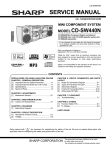
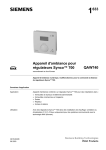
Mechanical design
The central communication unit consists of the housing lower section with printed circuit
boards and connection terminals. The upper housing section contains the printed circuit
boards. The LEDs, operating buttons, interfaces, and slots for the CF cards (compact
flash memory cards) are integrated in the upper housing section. These elements and
the connection terminals are labeled on the front of the housing. The shape and dimensions of the housing sections conform to DIN 43880 (size 2).
Basic design
1
2
3
4
5
6
7
8 9
XX:XX:XX:XX:XX:XX
OZW775
Q11 Q12 Q21 Q22 Q Q
Q Q
OZW775
XXXXXXXXXXXX HEX
OZW775
18 19 20 21
10 11 12 13
14 15 16 17 18
Position Labeling
1
2
3
4
5
6
7
8
9
10
11
12
13
14
15
16
17
18
19
20
21
22
23
24
25
26
27
19
20 21
22
23
5663Z01
040601A001001
24
25 26
27
Element
PC
D1...D8 M
X1...X8 M
USB interface
Connection terminal digital inputs
(M = ground)
Connection terminals universal inputs (M = ground)
Upper housing section
Modem
RS-232 interface
KNX
LED (green/red) Bus voltage, data exchange via KNX (green) / unit in addressing mode (red)
CE- CE+
KNX (Konnex) connection terminals
Ethernet
Ethernet plug RJ45 on Ethernet card OZZ7E5 (order card separately)
XX:XX:XX:XX:XX:XX MAC address (Media Access Control address, 48 bits)
Run
LED (green) Operating voltage applied (lit), communicating with ACS (flashing)
Local
LED (red)
Central unit faults or faults at fault inputs, or "Hours run for service reached"
System
LED (red)
Device faults in the KNX network
CF cards
LED (green) CF card integrated (lit), CF card being integrated or removed (flashing)
G G0
Connection terminals for AC 24 V operating voltage
Config
Button
Integrate or remove CF card
Ack
Button
Acknowledgement of "Local" fault, fault relay "System"
CF card memory
Slot for CF card (web server data)
CF Card Config/Report Slot for CF card (firmware update)
Q11,Q12 Q21,Q22
Connection terminals for 4 relays with NC contacts
Q31,Q32 Q41,Q42
Report
Button
For function, see “Button combinations“
Modem
Button
initializes modem, checks connection to the modem (short) / sends system report (long)
Q73,Q74 Q83,Q84
Connection terminals for 2 relays with NO contact
Lug for cable tie (cable strain relief)
Fastening spring to mount the central communication unit to a standard rail TH 35-7.5
Snap cover
Cover (can be opened without tools if Ethernet card OZZ7E5 needs to be inserted)
Lower housing section
5/18
Building Technologies
HVAC Products
Central communication unit OZW775 V3.0
CE1N5663en
29.06.2009
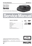
Technical design
The central communication unit contains various function blocks (FB). The functionality
of the unit can be extended by connecting (binding) the digital inputs N.D1…N.D8 and
the universal inputs N.X1…N.X8 to the FB inputs "d", "x", and "i" (see figure and
function block description).
Inputs and outputs
Digital inputs
The digital inputs N.D1…N.D8 help connect potential-free status contacts. They act as
fault inputs when connecting digital inputs to FB "Faults". When connected to FB
"Operating hours", the number of operating hours of aggregates (burners, pumps, fans,
etc.), can be counted.
The universal inputs N.X1…N.X8 can be configured for potential-free status and
counting impulse contacts and analog signals from sensors and transmitters.
Universal inputs
Universal inputs configured for status contacts (digital) or limit values (analog) and
connected to FB "Faults" act as fault inputs.
When universal inputs are configured for operating status contacts of aggregates and
connected to FB "Operating hours", the operating hours can be acquired.
When universal inputs are configured for counting pulses and connected to FB
"Meters", consumption values (heat, gas, electricity, etc.) can be acquired.
The outputs of relays N.Q1…N.Q4 have NC contacts, those of relays N.Q7, N.Q8 have
NO contacts. To signal faults (e.g. with signal lamps, horns), relay 1 and/or relay 2 of
FB "Faults" are connected to one of the relays N.Q_.
Relay outputs
If one of the relays N.Q_ is connected to an FB "7-day time switch with control switch",
relay N.Q_ in "Auto" position operates as per the time switch program, else per the
control switch position "Off" or "On".
N.D1
N.D2
d
N.D3
N.D4
d
d
x x
d
N.D5
x
d
d
x x x
x
N.D6
x x x
N.D7
d
x x
x x
N.D8
d
x x
d
R e la y 1
20
19
18
17
16
14
15
12
13
11
9
10
7
8
6
5
3
4
2
1
N.X2
x
Intern
N.X3
x
x x x x
Ack
Faults
N.X1
System
N.X4
x
N.X5
x
N.X6
x
N.X7
N.X8
x
x
x
d
d
d
d
d
i
i
i
i
i
i
i
i
1
2
3
4
5
1
2
3
4
5
6
7
8
Operating hours
Meters
R e la y 2
Q
Q
Ein/Aus
d
2 On/Off
1 On/Off
3 On/Off
4 On/Off
Message receivers
Receiver 1
1
Q
Q
Q
On/Off
2
Calendar
Q
Receiver 3
Receiver 2
On/Off
Calendar
c
c
3
On/Off
Calendar
c
Receiver 4
4
On/Off
Calendar
c
N.Q1
N.Q2
Q
Q
Q
Q
N.Q3
N.Q4
N.Q7
N.Q8
c
PC USB
c
Modem
c
Ethernet
5663B01en
Q
Input identifier
Sy ste m rep o rt
Q
Inputs, outputs and function blocks of the OZW775 central communication unit.
6/18
Building Technologies
HVAC Products
Central communication unit OZW775 V3.0
CE1N5663en
29.06.2009
Function blocks
FB "Faults"
FB "Faults" is designed for 20 fault inputs. Inputs N.D1…N.D8 (digital) and N.X1…N.X8
(digital/analog) are connected to FB inputs "x". "Relay 1" and/or "Relay 2" is activated
depending on fault priority and source.
FB "Faults" handles faults and failures of the Synco devices (“System“ faults) listed in
the device list as well as faults at the fault inputs and faults of the central
communication unit ("Local" faults)..
To facilitate external fault acknowledgement, a digital input must be connected to input
"Ack". External fault acknowledgement acts like pressing the "Ack" button.
FB "Operating hours"
FB "Operating hours" can handle up to 5 runtime totalizers. The operational status
contacts of the aggregates are connected to FB inputs "d" via the digital inputs
N.D1...N.D8 or N.X1...N.X8 (configured as digital inputs).
If a service interval is defined, the “Local“ LED indicates when the number of operating
hours is reached and, if configured, a service alarm is issued.
FB "Meters"
FB "Meters" can handle up to 8 counting values. The universal inputs N.X1…N.X8
(configured as counting pulses) are connected to the FB inputs "i". The acquired
counting pulses from heat, water, gas, electricity meters are converted to consumption
values, e.g. energy in Wh, kWh or volume in m3. The 15 monthly values along with
readout dates are stored.
FB "7-day time switch
with operation selector"
The 4 FB "7-day time switch with control switch" allow for switching various consumers
in dependence of time via the relays N.Q_. Each 7-day time switch allows for programming up to 6 switching points (3 "On", 3 "Off". Additionally, a configurable operation
selector with positions "Auto" / "Off" / "On" is integrated.
If a time switch output "Q" is connected to a relay input, position "Auto" ensures that the
relay is energized and deenergized as per the time program, or the relay is constantly
deenergized or energized.
FB "System report"
In FB "System report", the time the message is sent (hh:mm) and the message cycle
interval (1...255 days) for sending system reports can be programmed. A system report
is sent to one or several message receivers depending on fault priority (urgent/not
urgent).
FB "Message receivers"
FB "Message receivers" is subdivided into 4 receivers. Message suppression via input
"d" acts on all receivers. You can set both receiver type and fault priority individually for
each receiver. Each receiver has a "Time switch with calendar" to program three
sending times per day and holidays/special days.
Example: All fault messages from Monday through Friday 08:00 - 18:00 are sent to
receiver "Service business receiver", e.g. to a fax machine. Outside these hours, the
fault status messages are sent to receiver "24-hour service", e.g. SMS to mobile phone.
The outputs "c" of FB "Message receivers" are connected to inputs "c" of the PC USB,
modem, or Ethernet interfaces. The PC USB interface is designed for local commissioning, operation and monitoring (alarming).
Remote operation and monitoring are possible via modem (dial-up) and, at the same
time, via Ethernet (Internet/intranet) to one (or several) web browsers.
7/18
Building Technologies
HVAC Products
Central communication unit OZW775 V3.0
CE1N5663en
29.06.2009
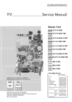
Plant diagrams
Plant diagrams in the OZW775 V3.0 allow users to display the entire HVAC installation
along with all data points. Users can view plant and room states from a user viewpoint,
thus gaining a better overview. In the event of faults, access to faulty equipment is
much faster. Clicking the diagram opens a dialog box for read/write parameters,
allowing users to change values as illustrated below for a change of "Comfort cooling
setpoint".
Plant diagrams also allow for integrating additional data such as links to plant, function,
and maintenance descriptions or data sheets. Integrating external links allowing users
to navigate to several plants is possible also. In addition, plant diagrams even allow
users to integrate current webcam pictures.
Interfaces
The central communication unit has three interfaces to communicate between unit and
user, and the interface or connection for the KNX bus.
PC
The "PC" interface is intended to directly connect a central communication unit to a
local operator station. A USB cable, type A-B, is required to this end.
Modem
The "Modem" interface is intended to connect a modem via RS-232. When communicating via modem, the following message recipients are supported: Operator stations
(PC/laptop with ACS software), SMS recipients, pagers, fax machines.
Ethernet
The interface labeled "Ethernet" corresponds to a RJ45 plug on the Ethernet card
OZZ7E5. Order the card separately and insert in the central communication unit. A
network cable Cat-5 is required to connect to the Ethernet (Ethernet category 5 cable).
KNX
The"KNX" labeled connection terminals CE+ and CE- are intended for the KNX bus.
For more information on the KNX bus, see data sheet N3127.
Parallel operation
We speak of parallel operation if one central communication unit is operated with two or
multiple operator stations. Also, e.g. with one operator station via USB, and/or via
modem, and/or via Ethernet.
8/18
Building Technologies
HVAC Products
Central communication unit OZW775 V3.0
CE1N5663en
29.06.2009
Operation,
monitoring, alarming
Communication connections for local monitoring and alarming (USB), and for remote
operation via modem and Ethernet.
Parameter settings for
message receivers
The following table lists all parameters for the communication connections that can be
set in each message receiver.
Receiver type
Interface
--- (Default)
Modem type
-
Email
Ethernet
ACS alarm
USB
Modem
Transmission protocol
-
-
xx
SMTP
xx
ACS protocol
Analog/ISDN
GSM
Ethernet
Mobile phone
Modem
xx
Analog/ISDN
TAP
GSM
SMS GSM
Analog
Fax protocol
GSM
Fax protocol
SMS GSM service
UCP
Fax machine
Pager
Modem
Modem
Analog/ISDN
TAP
GSM
TAP
SMS GSM service
No other selection
xx
Bold/Italics
Value cannot be set or not value entry required
No modem required
Default value
Example: Receiver type
Interface
Transmission protocol
= Email
= Ethernet
= SMTP
(Default if receiver type = Email)
(Default if receiver type = Email)
9/18
Building Technologies
HVAC Products
Central communication unit OZW775 V3.0
CE1N5663en
29.06.2009
Mounting notes
You must mount the central communication unit in a cabinet or control panel. Make
sure service can easily access the unit.
•
•
•
•
Standard mounting
Screwed-on mounting
Mounting position
Mounting and dimensions
On standard rail TH 35-7.5
Screwed to rear wall
Horizontal only
See "Dimensions"
Installation notes
Important notes
Observe the following important notes for mounting and installation:
• The central communication unit must be mounted in a cabinet or control panel,
as when mounted on a freely accessible wall, the relay output terminals
carrying mains voltage (bottom of the unit, terminals not covered) are not
protected against electric shock hazard.
• Run fuses, switches, wiring and earthing as per local regulations for electrical
installations.
• The relay contacts of the central communication unit can switch either mains
voltage or low-voltage. Applying both mains and low voltage is not permitted.
• You must connect circuits with relay contacts Q11, Q12 through Q41, 42 to the
same mains phase.
• You must connect circuits with relay contacts Q73, Q74 and Q83, Q84 to the
same mains phase.
• Connect only potential-free contacts to digital inputs D1…D8 and universal
inputs X1…X8 (configured for digital inputs signals).
• We do not recommend plant monitoring via PC interface in environments with
strong electromagnetic interference (e.g. in industrial environments with
electrical welding equipment).
Operating voltage
The central communication unit operates on AC 24 V and must meet requirements for
SELV / PELV (safety extra low-voltage / protective extra low-voltage).
Use only safety isolating transformers suited for 100 % duty (as per EN 61558-2-6).
Wiring
Plan sufficient space around the unit for easy wiring. The unit’s terminals are arranged
to eliminate cross-wiring of input and output lines to prevent faulty wiring to the greatest
extent possible.
The terminals for digital inputs, universal inputs, and the KNX bus are located at the top
of the unit (low-voltage side). The terminals for AC 24 V operating voltage and relay
outputs carrying mains voltage are located at the bottom (mains voltage side).
Connecting terminals
The terminals are designed for wire diameters of min. 0.8 mm or cross-sections of
0.5...2.5 mm2. See "Technical data".
10/18
Building Technologies
HVAC Products
Central communication unit OZW775 V3.0
CE1N5663en
29.06.2009
Commissioning notes
Authorized staff
Only authorized staff may commission and parameterize the central communication
unit as well as start the web server.
Select telephone service
provider and modem
You must select the telephone service provider and modem depending on the message
receiver type prior to commissioning. If you use a GSM modem, make sure that the
SIM card allows for data communication and that it is not protected by a PIN code.
IP address
Before activating the web server via the web browser on Ethernet, the network system
administrator must assign the IP address for the central communication unit.
Commissioning
Commission the central communication unit locally via PC interface using a PC/laptop.
The service tool ACS must be installed on the PC/laptop.
You need a USB cable, type A-B, to locally connect the PC interface of the
communication unit to the PC/laptop.
The installation instructions G5663xx (enclosed with unit), topic “Commissioning“ also
point out important commissioning issues.
Parameterization
Parameterize the central communication unit locally via PC interface using a PC/laptop
and service tool ACS.
Read the commissioning instructions C5663 for the associated procedure. The commissioning instructions PDF file is saved to the CD supplied with the unit. You can also
download the PDF file from www.siemens.com/synco
Web server
Local activation
Locally activate the web server following commissioning and parameterization of the
central communication unit.
You need a USB cable, type A-B, to locally connect the PC interface of the communication unit to the PC/laptop.
The installation instructions G5663xx (enclosed with unit) stress the following issues:
•
•
•
•
Activate via
Ethernet connection
Insert Ethernet card.
Update firmware.
Prepare web server data.
Start web browser with IP address 192.168.250.1 and login.
See the commissioning instructions C5663 for information on how to activate the web
server via Ethernet connection (Ethernet card OZZ7E5). The PDF file of the commissioning instructions are saved on the CD supplied with the unit. You can also download
the PDF file from www.siemens.com/synco
11/18
Building Technologies
HVAC Products
Central communication unit OZW775 V3.0
CE1N5663en
29.06.2009
LED displays
Run (green)
Local (red)
Dark
No operating voltage AC 24 V or unit is starting.
Lit
Unit ready to operate.
Flashing Communicating with ACS.
Dark
Lit
No fault (normal operating state).
Central communication unit faults and/or signal at fault inputs "Hours run for
service reached".
Flashing Fault unacknowledged.
System (red)
Dark
Lit
Without configured fault relay "System" in the OZW775:
No fault (normal operating state).
Device fault in KNX network.
With configured fault relay "System" in the OZW775:
Dark
No fault (normal operating state).
Lit
Device fault in KNX network, fault relay acknowledged.
Flashing Device fault in KNX network, fault relay unacknowledged.
CF cards (green)
Dark
No CF card integrated.
Lit
CF card integrated.
Flashing CF card is being integrated or removed
(after pressing button "long" on "Config").
KNX (green/red)
Dark
Steady green
Flashing green
Steady red
Operating buttons
Pressing the button briefly ("short") means <2 seconds, "long" >4 seconds.
Config
Short
Long
No function.
Integrate or remove CF card (or both CF cards).
Ack
Short
Long
Acknowledge "Local" fault, fault relay "System".
See “Button combinations“.
Report
Short
Long
No function.
See “Button combinations“.
Modem
Short
Long
Initializes modem, checks modem connection.
Initializes modem, sends system report to configured receivers.
Button combinations
For button combinations, always press "long" (>4 seconds).
Addressing mode
Simultaneously press "Modem" and "Report" (programming mode).
Restart central unit
Simultaneously press "Modem" and "Ack".
Default state
Simultaneously press "Modem", "Ack", and "Config".
Note: All configuration data and settings are reset. The device list and all unsent
messages are deleted. History data is not deleted.
No bus power supply.
Bus power supply available.
Data exchange via KNX.
Unit in addressing mode.
12/18
Building Technologies
HVAC Products
Central communication unit OZW775 V3.0
CE1N5663en
29.06.2009
General notes
Maintenance
The OZW775 central communication unit requires no maintenance (no battery
changes, no fuses). Clean the housing only with a dry cloth.
Repair
The central communication unit OZW775 cannot be repaired in the field. If faulty, return
to the Repair Center of the relevant Siemens Regional Company.
Disposal
The central communication unit is subject to directive 2002/96/EEC (WEEE, Waste of
Electrical and Electronic Equipment).
"Dispose of the device as electronic waste in compliance with European directive
2002/96/EEC (WEEE) and not as municipal waste. Observe all relevant national
regulations and dispose of the unit correctly. Comply with all local and currently valid
legislation".
Technical data
Power supply G, G0
Functional data
Digital inputs D1...D8
Universal inputs X1...X8
Operating voltage
Rated voltage as per EN 60950-1
Safety extra low-voltage (SELV) / protective extra low-voltage
(PELV) as per
Requirements for external safety isolating transformer
(100 % duty, max. 320 VA)
AC 24 V ± 20 %
AC 24 V
HD 384
EN 61558-2-6
Frequency
50 / 60 Hz
Power consumption OZW775
20 VA
Supply line fusing
Max. 10 A, transformer on primary
side
Clock reserve
46 h typical, min. 12 h
OZW775 device list
Up to 250 Synco devices
Number
8 (terminals D1...D8 and 1 ground
connection for 2 terminals each)
Contact sensing
Voltage
Current
DC 16.5 V
Typically 8 mA
Requirements for status / fault contacts
Signal coupling
Type of contact
Insulating strength against mains potential
Potential-free
Maintained contact
AC 3750 V as per EN 60950-1
Permissible resistance
Contact closed
Contact open
Max. 200 Ω
Min. 50 kΩ
Number
8 (terminals X1...X8 and 1 ground
connection for 2 terminals each)
Sensors
Passive
Active
LG-Ni1000, T1, Pt1000
DC 0...10 V
Transmitter
Active
DC 0...10 V
Contact sensing status / impulse contacts
Voltage
Current
DC 16.5 V
Typically 1 mA, max. 6 mA
Requirements for status contacts
Signal coupling
Type of contact
Insulating strength against mains potential
Potential-free
Maintained contact
AC 3750 V as per EN 60950-1
13/18
Building Technologies
HVAC Products
Central communication unit OZW775 V3.0
CE1N5663en
29.06.2009
Universal inputs
continued
Requirements for pulse inputs
Signal cables
Signal coupling
Type of contact
Mechanical signal source (Reed contact)
Max. pulse frequency
Min. pulse duration
Electronic signal source
Max. pulse frequency
Min. pulse duration
Insulating strength against mains potential
Line length for:
Passive sensor signals LG-Ni 1000, T1, Pt 1000
Active signals DC 0…10 V
Status and impulse contacts
Relay outputs
Q1_,Q2_,Q3_,Q4_,Q7_,Q8_
Number
Relay with NC contact
Relay with NO contact
AC 230 V
4 (terminals Q11,Q12 Q21,Q22,
Q31,Q32 Q41,Q42)
2 (terminals Q73,Q74 Q83,Q84)
Max. 300 m
Relay contact data
Switching voltage
AC current (NC)
AC current (NO)
At 250 V
At 19 V
Switch-on current
Max. AC 250 V, min. AC 19 V
Max. 2 A ohm., 2 A ind. (cos φ = 0.6)
Max. 4 A ohm., 3 A ind. (cos φ = 0.6)
Min. 5 mA
Min. 20 mA
Max. 10 A (1 s)
Guide values:
7
2 x 10 switchings (NC and NO)
6
2 x 10 switchings (NC)
6
4 x 10 switchings (NO)
5
3 x 10 switchings (NC)
5
6 x 10 switchings (NO)
5
3 x 10 switchings (NO only)
0.85 (NC and NO)
Insulating strength between:
Relay contacts and system electronics (reinforced insulation)
Neighboring relay contacts (operational insulation)
AC 3750 V, as per EN 60950-1
AC 1250 V, as per EN 60950-1
Screw terminals for:
Solid / stranded wire (twisted or with ferrule)
1 solid / stranded wire per terminal
2 solid / stranded wires per terminal (max. 2)
Min. Ø 0.8 mm
2
0.5...2.5 mm
2
0.5...1.5 mm
Interface
Standard
Device class
Baud rate
Modem interface
Max. 300 m
See data for signal-sending device
300 m
Line length
At 4 A ohm.
Red. fact. at ind. (cos φ = 0.6)
PC interface
100 Hz
5 ms
AC 3750 V as per EN 60950-1
Max. 3.15 A
Max. 5 A
Max. 13 A
B, C, D as per EN 60898
At 2 A ohm.
Inputs and outputs
25 Hz
20 ms (incl. max. 10 ms bounce time)
External supply line fusing
NC contact, non-renewable fuse (slow)
NO contact, non-renewable fuse (slow)
Automatic line cutout
Release characteristic
Contact life at AC 250 V
At 0.1 A ohm.
At 0.5 A ohm.
Connecting terminals
Recommendation: Shielded cables
Potential-free
Impulse contact
USB V1.1 (universal serial bus)
RNDIS (remote network device
Interface specification)
Max. 12 Mbps (full speed)
Connecting cable for operator station
Cable length
Cable type for connection to PC/laptop
Cable type for connection to OZW775
Max. 5 m
USB type A
USB type B
Interface
Standard
Baud rate
RS-232, V.24 / EIA 232D
Max. 115 kbaud
Connecting cable for modem
Cable length
Cable type for connection to OZW775
Max. 15 m
D-sub 9-pin, plugs
14/18
Building Technologies
HVAC Products
Central communication unit OZW775 V3.0
CE1N5663en
29.06.2009
Protocols to send
messages
Protocol support for connection via
Leased line telephone service provider
GSM telephone service provider, additional
KNX bus
Ethernet
Ethernet card OZZ7E5
Ambient conditions
Degree of protection
Standards
Interface type
2-wire bus
Bus load number OZW775
Decentralized bus power supply, can be switched off
TP1 (twisted pair, 1 cable pair)
CE+, CE- (non exchangeable)
E 0.3
DC 30 V / 25 mA
Permissible line length and cable types
See data sheet N3127
Interface type
Bit rate
Protocol
100BaseTX, IEEE 802.3 compatible
10 Mbps
TCP/IP
Connection
Cable type
Cable length
RJ45 plug (screened)
Standard Cat-5, UTP or STP
Max. 100 m
Ethernet cable for:
Point-to-point connection
Multi-connection (e.g. to switchbox)
Crossed cable
Straight cable
Operation to
Climatic conditions
Temperature (housing and electronics)
Humidity
Mechanical conditions
IEC 60 721-3-3
Class 3K5
0 ...50 °C
5...95 % r. h. (non-condensing)
Class 3M2
Transport
Climatic conditions
Temperature
Humidity
Mechanical conditions
IEC 60 721-3-2
Class 2K3
− 25...+ 70 °C
< 95 % r. h.
Class 2M2
Degree of protection when mounting:
Rear wall in cabinet or control panel
Front panel cutout for display and operation
IP 20 as per EN 60529
IP 30 as per EN 60529
Safety class
II as per EN 60950-1
Product safety
For information technology equipment
EN 60950-1
Electromagnetic compatibility
Immunity OZW775
Immunity PC interface
Emissions
Home and Building Electronic System (HBES)
EN 61000-6-2
EN 61000-6-1
EN 61000-6-3
EN 50090-2-2
conformity
EMC directive
Low voltage directive
Materials and colors
Dimensions
UCP (universal computer protocol)
TAP (telocator alphanum. protocol)
FAX protocol (fax class 2 or 2.0)
AT+ (extended AT command set)
2004/108/EC
2006/ 95/ EC
-conformity
Australian EMC Framework
Radio Interference Emission Standard
Environmental compatibility
The environmental product declaration CE1E5663en
contains data on environmentally compatible product design
and assessments (RoHS compliance, materials composition,
packaging, environmental benefit, disposal)
ISO 14001 (Environment)
ISO 9001 (Quality)
SN 36350 (Environmentally
compatible products)
2002/95/EC (RoHS)
Housing lower and upper section
Polycarbonate, RAL 7035 (light-gray)
Length x width x height (max. dimensions)
298 mm x 128 mm x 77 mm
Size
2 as per DIN 43880
Radio communication act 1992
AS/ NZS 3548
15/18
Building Technologies
HVAC Products
Central communication unit OZW775 V3.0
CE1N5663en
29.06.2009
Weight OZW775
Weight OZZ7E5
Weight OZZ7CF
Terms and abbreviations
Central communication unit OZW775
With packaging, installation instructions and CD
0.825 kg
1.185 kg
Packaging
Cardboard box
Ethernet card OZZ7E5
With packaging, mounting instructions
0.018 kg
0.044 Kg
Packaging
Cardboard box
CF card OZZ7CF
With packaging, operating instructions
0.010 kg
0.022 Kg
Packaging
Plastic bag
Extended command language for modems: Attention+
AT+
Global system for mobile communication
GSM
Integrated services digital networks
ISDN
Internet protocol
IP
Shielded twisted pair
STP
Simple mail transfer protocol
SMTP
Short message service
SMS
Telocator alphanumeric protocol
TAP
Transmission control protocol
TCP
Universal computer protocol
UCP
Universal serial bus
USB
Unshielded twisted pair
UTP
16/18
Building Technologies
HVAC Products
Central communication unit OZW775 V3.0
CE1N5663en
29.06.2009
Connection diagrams
Connection diagram
D1 M D2 D3 M D4 D5 M D6 D7 M D8 X1 M X2 X3 M X4 X5 M X6 X7 M X8 Modem CE- CE+ RJ45
D1…D8
X1…X8
M
CECE+
G, G0
Q…
Connection diagram
Q73 Q74 Q83 Q84
Q11 Q12 Q21 Q22 Q31 Q32 Q41 Q42
G G0
5662G02
Ethernet
Digital inputs
Universal inputs
Ground for digital inputs, measuring ground for universal inputs
KNX bus connection (negative)
KNX bus connection (positive)
Operating voltage AC 24 V
Relay outputs
G
F2
F1
B1
B2
N3
N2
G D1
M
D2 D3.......D8
X1
M
X2 X3.......X8
Modem
KNX
Ethernet
CE- CE+
RJ45
Q84
Q83
Q74
Q73
Q42
Q32
Q41
Q31
Q22
Q12
G0
Q21
Q11
Ethernet
N1
5663A02
AC 24 V
RS-232
0...10 V
K1
L
N
G0
N1
N2, N3
F1, F2
B1
B2
K1, K2
K3
Pin assignment
Ethernet card OZZ7E5
L
N
Central communication unit OZW775
Synco device in KNX network
Device with potential-free contact output
Sensor with passive signal
Transmitter with active signal
Contactor (control by relay with NC contact)
Contactor (control by relay with NO contact)
RJ45 plug (screened), standard assignment as per AT&T256.
5663Z21
3206Z01
12 34 5678
1
Tx +
5
Not used
2
3
Tx –
6
Rx –
Rx +
7
4
Not used
Not used
8
Not used
Modem connection (D-pins, 9-pin), interface definition as per RS-232.
9
5
8 7
4
3
6
2 1
5663Z22
Modem connection,
central communication
unit
K3
K2
1
DCD
Data carrier detect
6
DSR
Data set ready
2
RXD
Received data
7
RTS
Request to send
3
TXD
Transmit data
8
CTS
Clear to send
4
DTR
Data terminal ready
9
NC
Not connected
5
GND
Signal ground
17/18
Building Technologies
HVAC Products
Central communication unit OZW775 V3.0
CE1N5663en
29.06.2009
Dimensions
44
5663M01
5.3
45
35
128
78
111
TH35-7.5
298
Standard mounting on standard rail TH 35-7.5
298
1
128
5663M02
=
5663Z04
=
2
3
Screwed-on mounting
2
=
=
287
5663M04
5663Z05
=
100
=
1
Dimensions in mm
18/18
Building Technologies
HVAC Products
©2005-2009 Siemens Switzerland Ltd
www.sbt.siemens.com/
Central communication unit OZW775 V3.0
Subject to change
CE1N5663en
29.06.2009