1
1VIAYIAG
®
Series
Twelve
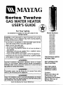
GAS WATER HEATER
For Your Safety
USER'S
GUIDE @
AN ODORANT IS ADDED TO THE GAS USED BY THIS
WATER HEATER
• Do not try to light any appliance.
• Do not touch any electrical switch; do not use any phone in
your building.
• Immediately call your gas supplier from a neighbor's phone.
Follow the gassupplier'sinstructions.
• If you can not reachyour gassupplier,call the fire department.
Model Numbers
HN41240X
HN51240X
HP41240X
HP51240X
HN41250X
HN51250X
HP41250X
HP51250X
HN41250Q
HN51250Q
HP41250Q
HP51250Q
HN41275Q
HN51275Q
HP41275Q
HP51275Q
-Installation and servicemustbe performed by a qualified installer,
serviceagencyor the gassupplier.
FOR POTABLE WATER
WARNING: If the information in these instructions are not followed exactly, a fire or explosion may result, causing property
damage, personal injury or death.
-Do not store or use gasoline or other flammable vapors and liquids in the vicinityof this or any other appliance.
-WHAT TO DO IF YOU SMELLGAS
HEATINGONLY
AWARNING
Improper installation, adjustment, alteration, service or maintenance can cause DEATH, SERIOUS BODILY INJURY,OR PROPERTY
DAMAGE. Refer to this manual for assistance or consult the local
gas utility for further information.
NOT SUITABLE FOR
SPACEHEATING
NOT FOR USE IN
(MOBILE)HOMES
Flammable vapors may be drawn by air currents from other
areas of the structure to AWARNING
th s app lance.
A,WARNING
READ THE GENERAL SAFETY SECTION BEGINNING ON INSIDE
COVER AND THEN THIS ENTIRE MANUAL BEFORE INSTALLING
OR OPERAT NG THIS WATER HEATER.
Save this Manual for Future Reference.
I
MANUFACTURED
Caution:
Read and Follow All
Safety Rules and
Operating Instructions
Before First Use of
This Product.
Safety Instructions
AWARNING
AWARNING
Improper installation, adjustment, alteration, service
or maintenance
can cause death, serious bodily
injury, or property damage. Refer to this manual for
assistance consult your local gas utility or call
Maytag Customer Service at 1-800-788-8899 for an
authorized servicer for further information.
At the time of manufacture this water heater was provided with a combination temperature-pressures relief
valve certified by a nationally recognized testing laboratory that maintains periodic inspection of production
of listed equipment or materials, as meeting the
requirements for Relief Valves and Automatic Gas
Shutoff Devices for Hot Water Supply Systems, and
the latest edition of ANSI Z21.22 and the code require-
&WARNING
requirements
of local
codes, but
lessthan
a combiments of ASME.
If replaced,
the not
valve
must meet
the
nation temperature and pressure relief valve certified
as meeting the requirements for Relief Valves and
Automatic Gas Shutoff Devices for Hot Water Supply
Systems, ANSI Z21.22 by a nationally recognized testing laboratory that maintains periodic inspection of
production of listed equipment or materials.
The valve must be marked with a maximum set pressure not to exceed the marked hydrostatic working
pressure of the water heater (150 Ibs./sq. in.) and a
discharge capacity not less than the water heater
input rate as shown on the model rating plate.
(Electric heaters - watts divided by 1000 x 3415 equal
BTU/Hr. rate.)
Your local jurisdictional authority, while mandating the
use of a temperature-pressure relief valve complying
with ANSI Z21.22 and ASME, may require a valve model
different from the one furnished with the water heater.
Compliance with such local requirements must be satisfied by the installer or end user of the water heater
with a locally prescribed temperature-pressure relief
valve installed in the designated opening in the water
heater in place of the factory furnished valve..
For safe operation of the water heater, the rehef valve
must not be removed from it's designated opening or
plugged.
The temperature-pressure
relief valve must be
installed directly into the fitting of the water heater
designated for the relief valve. Position the valve
downward and provide tubing so that any discharge
will exit only within 6 inches above, or at any distance
below the structural floor. Be certain that no contact is
made with any live electrical part. The discharge opening must not be blocked or reduced in size under any
circumstances.Excessivelength, over 30 feet, or use of
more than four elbows can cause restriction and
reduce the discharge capacity of the valve.
No valve or other obstruction is to be placed between
the relief valve and the tank. Do not connect tubing
directly to discharge drain unless a 6_ air gap is provic[ed. To prevent bodily injury, hazard to life, or property
damage, the relief valve must be allowed to discharge
water in quantities should circumstances demand. If
the discharge pipe is not connected to a drain or other
suitable means, the water flow may cause property
damage.
The Discharge Pipe:
• Must notbe smaller in size than the outlet pipe size
of the valve, or have any reducing couplings or
other restrictions.
• Must not be plugged or blocked.
• Must be of material listed for hot water distribution.
|WATER HEATERS EQUIPPED FOR ONE TYPE GAS
|ONLY: This water heater is equipped for one type
gas only. Check the model rating plate near the gas
control valve for the correct gas. DO NOT USE THIS
WATER HEATER WITH ANY GAS OTHER THAN THE
ONE SHOWN ON THE MODEL RATING PLATE. Failure
to use the correct gas can cause problems which can
result in DEATH, SERIOUS BODILY INJURY, OR PROPERTY DAMAGE. If you have any questions or doubts
consult your gas supplier or local utility,
AWARNING
INSTALLATIONS IN AREAS WHERE FLAMMABLE LIQUIDS (VAPORS) ARE LIKELYTO BE PRESENTOR STORED
(GARAGES, STORAGE, AND UTILITY AREAS, ETC):
I Flammable liquids (such as gasoline, solvents, propane
(LP) or butane, etc.), all of which emit flammable
vapors, may be improperly stored or used in such
areas. The gas water heater pilot light or main burner
can ignite such vapors, The resulting flashback and fire
can cause death or serious burns to anyone in the
area, as well as property damage,
If installation in such areas is your only option, then
the installation must be accomplished in a way that
the pilot flame and main burner flame are elevated
from the floor at least 18 inches, While this may reduce
the chances of flammable vapors from a floor spill
being ignited, gasoline and other flammable substances should never be stored or used in the same
room or area containing a gas water heater or other
open flame or spark producing appliance,
NOTE: Flammable vapors may be drawn by air currents
from other areas of the structure to the appliance,
AWARNING
If this water heater will be used in beauty shops,
barber shops, cleaning establishments, or self-service laundries with dry cleaning equipment,
it is
imperative that the water heater or water heaters
be installed so that combustion and ventilation air
be taken from outside these areas. Refer to the
"Locating The New Water Heater" section of this
manual and also the latest edition of the National
Fuel Gas Code, ANSI Z223.1, also referred to as NFPA
54 for specifics provided concerning air required,
AWARNING
A fire can start if combustible materials such as
clothing, cleaning materials, or flammable liquids
are paced against or next to the water heater.
2
both
temperature-pressure
relief valve,
and
• of
Must
be the
installed
so as to allow complete
drainage
the discharge pipe.
• Must terminate at an adequate drain.
• and
Musttank.
not have any valve between the relief valve I
Safety Instructions
AWARNING
AWARNING
A gas water heater cannot operate properly without
the correct amount of air for combustion. Do not
install in a confined area such a closet, unless you
provide air as shown in the "Locating The New
Water Heater" section. Never obstruct the flow of
ventilation air. If you have any doubts or questions
at all, call your gas company. Failure to provide the
proper amount of combustion air can result in a fire
or explosion and can cause DEATH, SERIOUS BODILY
INJURY, OR PROPERTYDAMAGE.
This water heater must not be installed directly on
carpeting. Carpeting must be protected by a metal
or wood panel beneath the appliance extending
beyond the full width and depth of the appliance by
at least 3 inches (76.2mm) in any direction, or if the
appliance is installed in an alcove or closet, the
entire floor must be covered by the panel. Failure to
heed this warning may result in a fire hazard.
AWARNING
VENT DAMPERS - Any vent damper, whether it is
operated thermally or otherwise must be removed if
its use inhibits proper drafting of the water heater.
Thermally Operated Vent Dampers: Gas-fired water
heaters having thermal efficiency in excess of 80%
may produce a relatively low flue gas temperature.
Such temperatures may not be high enough to properly open thermally operated vent dampers. This
would cause spillage of flue gases and may cause
carbon monoxide poisoning.
Vent dampers must bear evidence of certification as
complying with the latest edition of American
National Standard ANSI Z21.68 (ANSI Z21.66 & 67,
respectively, cover electrically and mechanically actuated vent dampers). Before installation of any vent
damper, consult your local gas utility for further
information.
AWARNING
HOTTER WATER CAN SCALD: Water heaters are
intended to produce hot water. Water heated to a
temperature which will satisfy clothes washing, dish
washing, and other sanitizing needs can scald and
permanently injure you upon contact. Some people
are more likely to be permanently injured by hot
water than others. These include the elderly, children,
the infirm, or physically/mentally
handicapped. If
anyone using hot water in your home fits into one of
these groups or if there is a local code or state law
requiring a certain temperature water at the hot
water tap, then you must take special precautions. In
addition to using the lowest possible temperature
setting that satisfies your hot water needs, a means
such as a mixing valve, should be used at the hot
water taps used by these people or at the water
heater. Mixing valves are available at plumbing supply or hardware stores. Follow manufacturers instructions for installation of the valves. Before changing
the factory setting on the thermostat,
read the
"Temperature Regulation" section in this manual.
AWARNING
* The appliance and its individual shutoff valve must
be disconnected from the gas supply piping system
during any pressure testing of the gas system at
test pressures in excess ofl/2 pound per square
inch (3,5kPa).
The appliance must be isolated from the gas supply piping system by closing its individual manual
shutoff valve during any pressure testing of the
gas supply piping system at test pressures equal or
less than 1/2 pound per square inch (3.SkPa).
AWARNING
Soot build-up indicates a problem that requires correction before further use. Turn "off" gas to water
heater and leave "off" until repairs are made,
because failure to correct the cause of the sooting
can result in a fire or explosion causing DEATH, SERIOUS BODILY INJURY, OR PROPERTYDAMAGE.
AWARNING
AWARNING
Chemical vapor corrosion of the flue and vent system may occur if air for combustion contains certain
chemical vapors. Spray can propellants, cleaning solvents, refrigerator and air conditioner refrigerants,
swimming pool chemicals, calcium and sodium chloride, waxes, bleach, and process chemicals are typJcal compounds which are potentially corrosive,
BEFORE LIGHTING [PROPANE (L.P.) GAS WATER
HEATERS]: Propane (L.R) gas is heavier than air.
Should there be a leak in the system, the gas will settie near the ground. Basements, crawl spaces, skirted
areas under manufactured (mobile) homes (even
when ventilated), closets and areas below ground
level will serve as pockets for the accumulation of this
gas. Before attempting to light or relight the water
eater's pilot or turning on a nearby electrical light
switch, be absolutely sure there is no accumulated
ground level in the vicinit_ of the appliance. If odor is
detected,
gasthe
in the
follow
area.page
Search
steps
for
of
at "For
gas
by
Your
sniffing
Safety"
at
on
cover
of indicated
this odor
manual
then
leave
the
Obstructed or deteriorated vent systems may
ent a serious health _,WARNING
risk or asphyxiation.
pres-
premises.
3
Safety Instructions continued on page 4.
Safety Instructions
_,WARNING
The water heater with draft hood installed must be
properly vented to a chimney which terminates outdoors. Never operate the water heater unless it is
vented to the outdoors and has adequate air supply
to avoid risks of improper operation, explosion or
asphyxiation.
AWARNING
Minimum clearances between the water heater and
combustible and noncombustible construction are 1'p
at the sides and rear, 4" at the front, and 6" from the
vent pipe. Clearance from the top of the jacket is 18"
on most models. Note that a lesser dimension may be
allowed on some models. Refer to the label on the
water heater adjacent to the gas control valve for all
clearances.
AWARNING
Flood damage to a water heater may not be readily
visible or immediately detectible. However, over a
period of time a flooded water heater will create
dangerous conditions which can cause DEATH, SERIOUS BODILY INJURY OR PROPERTY DAMAGE.
Contact the Maytag dealer from whom the appliance was purchased or call Maytag Customer Service
at 1-800-788-8899
for an authorized servicer to
replace a flooded water heater, Do not attempt to
repair the unit! It must be replaced!
AWARNING
HYDROGEN GAS: Hydrogen gas can be produced in
a hot water system that has not been used for a
long period of time (generally two weeks or more).
Hydrogen gas is extremely flammable and explosive.
To prevent the possibility of injury under these conditions, we recommend the hot water faucet be
opened for several minutes at the kitchen sink
before any electrical appliances which are connected
to the hot water system are used (such as a dishwasher or washing machine). If hydrogen gas is
present, there will probably be an unusual sound
similar to air escaping through the pipe as the hot
water faucet is opened. There must be no smoking
or open flame near the faucet at the time it is open.
_WARNING
INSULATING JACKETS; When installing an external
water heater insulation jacket on a gas water heater:
• DO NOT cover the temperature-pressure relief valve.
• DO NOT put insulation over any part of the top of
the gas water heater.
• DO NOT put insulation over the gas control valve or
gas control valve/burner cover, or any access areas
to the burner.
• DO NOT let insulation around the gas water heater
to get within 8 inches of the floor (air must get to
the burner).
• DO NOT cover or remove operating instructions,
and safety related warning labels and materials
affixed to the water heater.
Failure to heed this will result in the possibility of a
fire or explosion.
ACAUTION
WATER HEATERS EVENTUALLY LEAK: Installation of
the water heater must be accomplished in such a
manner that if the tank or any connections should
leak, the flow of water will not cause damage to
the structure. For this reason, it is not advisable to
install the water heater in an attic or upper floor.
When such locations cannot be avoided, a suitable
drain pan should be installed under the water
heater. Drain pans are available at your local hardware store. Such a drain pan must be not greater
than 1½ inches deep, have a minimum length and
width of at least 2 inches greater than the water
heater dimensions and must be piped to an adequate drain. The pan must not restrict combustion
air flow. Under no circumstances is the manufacturer to be held liable for any water damage in connection with this water heater.
Table of Contents
Safety Instructions ........................................................................................
2-4
Table of Contents ....................................................................................................
.5
Customer Information .....................................................................................
.6
Product Specifications
...........................................................................................
.7
Accessories and Tools Needed .........................................................................
7
Accessories ........................................................................................................................................................................
Tools
.7
.....................................................................................................................................................................................
Instructions
for Installation
7
.................................................................................
8-17
Removing the Old Water Heater ..........................................................................................................................................
8
Typical Installation ...............................................................................................................................................................
9
Locating the New Water Heater. .....................................................................................................................................
10
Combustion Air and Ventilation for Appliances in Unconfined Spaces .............................................................................
11
Combustion Air and Ventilation for Appliances in Confined Spaces ...........................................................................
11-12
Water Piping .................................................................................................................................................................
13
Temperature-Pressure Relief Valve .................................................................................................................................
14
Filling the Water Heater ...............................................................................................................................................
15
Venting ........................................................................................................................................................................
15-16
Gas Piping .................................................................................................................................................................
16-17
Installation Checklist ........................................................................................................................................................
18
Instru cfion.s...fo.r..
_pe:::::::::::::::::::::::::::::::::::::::::::::::::::::::::::::::::::::::
::::::::::::::::::::::::::::
Temperature
Regulation .................................................................................................................................................
Service and Maintenance
.21
.................................................................................
2>z4
Venting System Inspection. ..............................................................................................................................................
Burner Inspection ........................................................................................................................................................
kP. Gas Control Valve and Burner Assembly Replacement Information .........................................................................
Burner Cleaning ...........................................................................................................................................................
Draining. .........................................................................................................................................................................
Temperature-Pressure Relief Valve Operation ...............................................................................................................
Drain Valve Washer Replacement ..................................................................................................................................
Housekeeping ................................................................................................................................................................
Service .............................................................................................................................................................................
Condensation .............................................................................................................................................................
Smoke/Odor ...............................................................................................................................................................
.22
.22
.23
23
23
23
.24
24
.24
.25
.25
Thermal Expansion ...................................................................................................................................................
Strange Sounds. ............................................................................................................................................................
Operational Conditions ................................................................................................................................................
Smelly Water ................................................................................................................................................................
Air in Hot Water Faucets ..............................................................................................................................................
.25
.25
.26-27
26
26
High Temperature Shut Off System ............................................................................................................................
Not Enough Hot Water ..............................................................................................................................................
Water is too Hot ........................................................................................................................................................
.26
26
..27
Leakage Checkpoints ................................................................................................................................................
Repair Parts List
..................................................................................................................................
28
29-35
Warranty ....................................................................................................................
36
Customer Information
Thank You for purchasing
a Maytag water heater,
Properly installed and maintained, it should give you years of
trouble free service. It is strongly suggested that this new water
heater be professionally installed, contact Maytag Customer
Service (1-800-788-8899) for recommended installers.
and be aware of. All warnings and all instructions are essential
to the proper operation of the water heater and your safety.
Since we cannot put everything on the first few pages, READ
THE ENTIRE MANUAL BEFORE ATTEMPTING
TO
INSTALL OR OPERATETHE
WATER HEATER.
• The installation must conform with the instructions in this
Abbreviations Found In This Instruction Manual
CSA - Canadian Standards Association
ANSI - American National Standards Institute
NFPA - National Fire Protection Association
manual; gas company rules; and Local Codes, or in the
absence of Local Codes, with the latest edition of the
National Fuel Gas code, ANSI Z223.1, also referred to as
NFPA 54. This publication is available from your local government or public library or gas company or by writing
NFPA, Batterymarch Park, Quincy, MA 02269.
• After reading this manual you have any questions or do not
understand any portion of the instructions, call Maytag
Customer Service at 1-800-788-8899 for an authorized servicer.
&WARNING
This gas-fired
water
heater is design
certified
by CSA
INTERNATIONALunder American National Standard/CSA
Standard ANS Z21,10.1 • CSA 4.1 (latest edition) for gas
water heaters. The installation must conform with this
manual,Local Codes and with the latest edition of the
National Fuel Gas Code, ANSI Z223.1.
This publication is available from your local government
or public library, gas company, or by writing NFPA,
Batterymarch Park, Quincy, MA 02269.
• Carefully plan the place where you are going to put thewater
heater. Correct combustion, vent action, and vent pipe installation are very important in preventing death from possible
carbon monoxide poisoning and fires.
Examine the location to ensure the water heater complies with
the "Locating the New Water Heater" section in this manual.
• For California installation this water heater must be braced,
• Read the "Safety Instructions" section, pages 2, 3 and 4 of this
manual first and then the entire manual carefully.If you don't
follow the safety rules, the water heater will not operate prop-
anchored, or strapped to avoid falling or moving during an
earthquake. See instructions for correct installation procedures. Instructions may be obtained from your local dealer,
wholesaler, public utilities or California Office of the State
Architect, 400 P Street, Sacramento, CA 95814.
erly. It could cause DEATH, SERIOUS BODILY INJURY
AND/OR PROPERTY DAMAGE.
• Massachusetts Code requires this water heater to be installed
in accordance with Massachusetts 248-CMR 2.00: State
• This manual contains instructions for the installation, operation, and maintenance of the gas-fired water heater. It also
contains warnings through out the manual that you must read
Plumbing Code and 248-CMR 5.00.
• Compiles with SCAQMD rule #1121 and districts having
equivalent NOx requirements.
Product Specifications
Model
HN41240X
•HN51240X
HP41240X
*HP51240X
HN41250X
'HN51250X
HP41250X
*HP51250X
HN41250Q.
*HN51250Q
HP41250Q
*HP51250Q
HN41275Q.
*HN51275Q
HP51275Q.
*HPS1275Q
40
40
50
50
50
50
75
75
Natural
Propane
Natural
Propane
Natural
Propane
Natural
Propane
Rate
Recovery Rate
In Gals Per Hour
@90°F Rise
Minimum
40,000
38_000
40,000
39_000
52fi00
48_000
75_100
75,200
46
44
46
45
57
52
79
79
Vent Pipe
Diameter
3" or 4"
20"
3" or 4"
20"
3" or4"
22"
3" or 4"
22"
4"
22"
4"
22"
4"
265"
4"
26.5"
Height To
Top of
Draft Hood
65"
65"
64"
64"
64"
64"
67.5"
67.5"
Tank Capadty
In Gallons
Type of
Gas
B.T.U.
• High altitude models have a B,T.U./Recovery
Rate 10% less than shown.
6
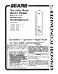
Accessoriesand Tools Needed
Accessories
To simplify the installation Maytag has available the instaLlation parts shown below. You may or may nor need all of these
accessories depending on your type of installation. Call
Ma_ag
Customer
ized installen
Service
at 1-800-788-8899
for an author-
DRAINPANSAVAILABLEIN 22" DIAMETER
EXPANSIONTANKS FORTHERMALEXPANSION
CONDITIONSAVAILABLEIN Z GALLON(PART
NUMBER66001013) AND 5 GALLON(PART
NUMBER66001014) CAPACITY
(PARTNUMBER 66001011) FORWATER
HEATERSHAVING A DIAMETER20" OR LESS,
24" DIAMETER(PARTNUMBER 66001105) FOR
WATERHEATERSHAVING A DIAMETER22"
OR LESSAND AVAILABLEIN 28" DIAMETER
(PARTNUMBER 66001012) FORWATER
HEATERSHAVING A DIAMETER26" OR LESS
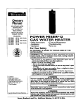
Tools
ADDITIONALTOOLSNEEDED
WHEN SWEATSOLDERING
You may or may not need all of these tools, depending on your
type of installation. These tools can be purchased at your local
hardware
store.
• Pipe Wrenches
• Screwdriver
•
•
•
••
Propane Torch
Tubing
Cutters or Hacksaw
Soft Solder
• Solder Flux
(2) 14"
6 Foot Tape of Folding Rule
Garden Hose
Drill
Tin
PipeSnips
dope or Teflon Tape
Wire -Brushes
_
GARDENHOSE
i
_
EmervCIoth
HACKSAW
6 FOOTTAPE
P,PE
WRENCH
ROLLOF TEFLONTAPE
(USE ONLYON WATER
CONNECTIONS)
_
SLOT-HEADSCREWDRIVER
_ _
3/4" WIRE BRUSH
1/2" WIRE BRUSH
_
PROPANETORCH
TIN SNIPS
PHILLIPSSCREWDRIVER
PIPEDOPE(SQUEEZETUBE)
GASCONNECTIONS)
(USE
FORWATERAND
ROLLOE LEADFREE
SOFTSOLDER
]
[1
ROLLOF EMERY
CLOTH
_._
7
SOLDERFLUX
TUBING CUTTER
Instructions for Installation
Removing the Old Water Heater
Turn "OFF" the gas supply to the water heater.
@
Disconnect
thewater
vent pipe
from
hood where
connect to the
heater.
In the
mostdraft
installations
the they
vent
A,WARNING
pipe can be lifted off after any screw or other attached
devices are removed. Dispose of the draft hood. The new
water heater has the draft hood which must be used for
proper operation.
If the maingas line shutoffservingall gasappliancesis used,
also shut "off" the gas at eachappliance.Leaveall gasappliancesshut"off" unti/the water heaterinstallationiscomplete,
a. If you have copper piping to the water
"_
@
@
_
i_IIIZ:__t'_
Turn "OFF" the water to the water
[_
__
necessary.
heater,
the Disconnect
two copper the
water
temperaturepipes can
pressure
relief
valve
drain
line.
When
Additional cuts can be made later
if
_
the water
heatertheis drain
drained,
disconnect
the
hose from
valve.
Close
the drain valve. The water heater is
_
heater. Some installations require that
the water he turned off to the entire
I
house.
now completely disconnected and
@
Check again to make sure the gas supply is "OFF" to the water heater. Then
ready to be removed.
I
_
_
@
from the gas control valve,
valve and put the other end in a floor
drain or outdoors. Open the water
heater drain valve. Open a nearby hot
water faucet which will relieve pressure
in the water heater and speed draining,
b. If you have galvanized pipe to the water
with a pipe wrench at the union in each
line. Also disconnect the piping
I
disconnect the gas supply connection
Attach a hose to the water heater drain
four inches away from where they connect to the water heater. This will
be cut with a hacksaw approximately
avoid cutting off the pipes too short.
__
t
_
_
heater, loosen the two galvanized pipes
pieces
should
be saved
they
may
remaining
to the
water since
heater.
These
be needed when reconnecting the new
water heater. Disconnect the temperature-pressure relief valve drain fine.
When the water heater is drained, disconnect the hose from the drain valve.
Close the drain valve. The water heater
ready to be removed.
I__
is now completely disconnected and
AWARNING
1"hewater passingout _may
beextremelyhot.
To avoidbeingscalded,makesureall connections
aretight and
that thewater flow isdirectedaway fromanyperson.
[
&CAUTION
|Mineral buildupor sedimentmay haveaccumulatedin the old
/water heater,Thiscausesthe water heaterto be muchheavier
8
] than normalandthisresidue,if spilledout,couldcausestaining.
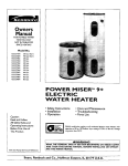
Instructions for Installation (cont'd)
Typical Installation
CHECK ALL CONNECTIONS FOR LEAKS. CONSULTTHE LOCAL UTILITY COMPANY TO EXAMINE INSTALLATION FOR PROPRIETYAND SAFETY.
VACUUMRELIEF
REQUIRED
BYSOMECODES
HOTWATEROUTLET
___
(REFER
TOLOCALCODES)
_ [J-_j _l_
COLDWATERINLET
ooc
WATER
TEMPERED
OUTLET_
*MIXINGVALVE
_ iL_
_
i=
TEMPERATURE-PRESSURE
RELIEF
VALVE
SUPPLY
DISCHARGE
PIPE
(Do notcapor plug)
DRAIN
PAN" -- S
TO
SUI,A.,E
DRA..
This appliance has been design certified as complying with American National Standard/CSA Standard for water heaters and is consideredsuitable for:
Water (Potable) Heating: All models are "considered suitable for water (potable) heating."
AWAR.,NG
]
[
HOTTER WATER CAN SCALD: Water heaters are I
intended to produce hot water. Water heated to a
temperature
will sanitizing
satisfy clothes
dish washing, which
and other
needs washing,
can scald I
/This water heater shall not be connected to any heatling systems or component(s) previously used with a
[non-potable water heating appliance.
and permanently injure you upon contact. Some l
people are more likely to be permanently injured by
hot water than others. These include the elderly,
children, the infirm, or physically/mentally
handicapped. If anyone using hot water in your home fits
into one of these groups or if there is a local code or
state law requiring a certain temperature water at
the hot water tap, then you must take special precautions. In addition to using the lowest possible
temperature settingthat
satisfies your hot water
needs, a means such as a mixing valve, should be
used at the hot water taps used by these people or
at the water heater. Mixing valves are available at
plumbing supply or hardware stores. Follow manuacturers instructions for installation of the valves.
Before changing the factory setting on the thermostat, read the "Temperature Regulation" section in
this manual.
|
_
A WARNING
--/Toxic chemicals such as used for treatment of boilers
|or non-potable water heating appliances shall never
|be introduced into a potable water space heating
/system.
NOTE: To protect against untimely corrosion of hot and
cold water fittings, it is strongly recommended that di-electricunions orcoupfingsbeinstaUedonthiswaterheater
when connected to copper pipe.
9
Instructions for Installation (cont'd)
Locating the New Water
Heater
AWARNING
Yon should carefully choose an indoor location for the new
This water heater must not be installed directly on
carpeting. Carpeting must be protected by a metal
or wood panel beneath the appliance extending
beyond the full width and depth of the appliance
by at least 3 inches (76.2mm) in any direction, or if
the appliance is installed in an alcove or closet, the
entire floor must be covered by the panel. Failure to
water heater, because the placement is a very important consideration for the safety of the occupants in the building and
for the most economical use of the appliance. This water
heater is not for use in manufactured (mobile) homes or outdoorinstaUation,
heed this warning may result in a fire hazard.
Whether replacing an old water heater or putting the water
heater in a new location, the following critical points must be
observed.
AWARNING
[
Minimum clearances between the water heater and [
combustible
and noncombustible
construction
are
1" at the sides and rear, 4" at the front, and 6 from
the vent pipe. Clearance from the top of the jacket [
is 18" on most models. Note that a lesser dimension
may be allowed on some models. Refer to the label
The location selected should be indoors as close as practical to
the gas vent or chimney to which the water heater vent is going
to be connected, and as centralized with the water piping system
as possible. The water heater, as all water heaters, will eventually
leak. Do not install without adequate drainage provisions where
valve°n
theforWaterall
clearances.heater
adjacent
water flow will cause damage,
&CAUTION
WATER HEATERS EVENTUALLY LEAK: Installation of
the water heater must be accomplished in such a
manner that if the tank or any connections should
leak, the flow of water will not cause damage to
the structure. For this reason, it is not advisable to
install the water heater in an attic or upper floor.
When such locations cannot be avoided, a suitable
drain pan should be installed under the water
heater, Drain pans are available at your local hardware store. Such a drain pan must be not greater
than 1'/2 inches deep, have a minimum length and
width of at least 2 inches greater than the water
heater dimensions and must be piped to an adequate drain. The pan must not restrict combustion
air flow. Under no circumstances is the manufacturer to be held liable for any water damage in connection with this water heater.
,2,, HAX.
[_-
_
to the gas contro
I"
L_-
I" MIN.
•
1_
VENTILATION
AiR O
OPENINGS
)
_
TOPVIEW
OF CLOSET
TOP VIEW I" HIN.
WITHOUT
DOOR OFCLOSET
_'MAX
WITHDOOR
FRONT VIEW
OFOOOg
_CTm_ULAR
3"
HIN.
AmOUCT
II Figure 1 II
AWARNING
AWARNING
Propellants of aerosol sprays and volatile compounds, (cleaners, chlorine based chemicals, refrigerants, etc.) in addition to being highly flammable
n many cases, will also change to corrosive
lydrochloric acid when exposed to the combustion
:)roducts of the water heater. The results can be
_azardous, and also cause _roduct failure,
A gas water heater cannot operate properly without the correct amount of air for combustion. Do
not install in a confined area such a closet, unless
you provide air as shown in the "Locating The New
Water Heater" section. Never obstruct the flow of
ventilation air, If you have any doubts or questions
at all, call your gas company. Failure to provide the
proper amount of combustion air can result in a fire
or explosion and can cause DEATH, SERIOUS BODILY INJURY, OR PROPERTY DAMAGE.
The location selection must provide adequate clearances for
servicing and proper operation of the water heater.
10
Instructions for Installation
Locating the New Water
Heater (cont'd)
(cont'd)
Combustion Air and Ventilation
for Appliances Located in
Unconfined Spaces
&WARNING
Unconfined Space is a space whose volume is not less than
If this water heater will be used in beauty shops,
barber shops, cleaning establishments, or self-service laundries with dry cleaning equipment,
it is
imperative
that
the
water
heater
or
water
heaters
be installed so that combustion and ventilation air
50 cubic feet per 1,000 Btu per hour of the aggregate input
rating of all appliances installed in that space. Rooms com
mnnicating directly with the space in which the appliances are
installed, through openings not furnished with doors, are con-
be taken from outside these areas. Refer to the
"Locating The New Water Heater" section of this
manual and also the latest edition of the National
Fuel Gas Code, ANSI Z223.1, also referred to as NFPA
54 for specifics provided concerning air required,
sidered a part of the unconfined space
In unconfined spaces in buildings, infiltration may be adequate to provide air for combustion, ventilation and dilution
of flue gases. However, in buildings of tight construction (for
example weather stripping heavily insulated, caulked, vapor
barrier, etc.), additional air may need to be provided using the
methods described in Combustion Air and Ventilation for
&WARNING
Appliances Located in Confined Spaces, b.
INSTALLATIONS IN AREAS WHERE FLAMMABLE LIQ-]
UIDS (VAPORS) ARE LIKELYTO BE PRESENTOR STORED[
(GARAGES, STORAGE, AND UTILITY AREAS, ETC): I
Flammable liquids (such as gasoline, solvents, propane I
(LP) or butane, etc.), all of which emit flammable I
vapors, may be improperly
stored or used in such
areas. The gas water heater pilot light or main burner
Combustion
A__
Air and Ventilation
__ I- i
for /ppllances Located in
Confined =paces
can ignite such vapors. The resulting flashback and fire
can cause death or serious burns to anyone in the
area, as well as property damage,
If installation in such areas is your only option, then
the installation must be accomplished in a way that
the pilot flame and main burner flame are elevated
from the floor at least 18 inches. While this may
reduce the chances of flammable vapors from a floor
spill being ignited, gasoline and other flammable substances should never be stored or used in the same
room or area containing a gas water heater or other
open flame or spark producing appliance,
NOTE: Flammable vapors may be drawn by air currents
from other areas of the structure to the appliance,
Confined Space is a space whose volume is less than 50 cubic
feet per 1,000 Btu per hour of the aggregate input rating of all
appliances installed in that space.
a. ALL AIR FROM INSIDE BUILDINGS:
(See Page 10 Figure 1, and Figure 2 below)
The confined space shall be provided with two permanent
openings communicating directly with an additional
room(s) of sufficient volume so that the combined volume
of all spaces meets the criteria for an unconfined space. The
total input of an gas utilization equipment installed in the
combined space shall be considered in making this determination. Each opening shall have a minimum free area of
one square inch per 1,000 BTU per hour of the total input
rating of all gas utilization equipment in the confined
space, but not less than 100 square inches. One opening
shall commence within 12 inches of the top and one commencing within 12 inches of the bottom of the enclosure.
-,,4_ CHIMNEY OR GAS VENT
FUR
[ Figure 2 ]
11
W/_TER
R
OPENINQ8
Instructions for Installation (cont'd)
b. ALl. AIR FROM OUTDOORS: (see Figures 3-5)
The confined space shall be provided with two permanent
openings, one commencing within 12 inches of the top and
one commencing within 12 inches from the bottom of the
enclosure. The openings shall communicate directly, or by
ducts, with the outdoors or spaces (crawl or attic) that
3. When communicating with the outdoors through horizontal ducts, each opening shall have a minimum free area of 1
square inch per 2,000 BTU per hour of total input rating of
all equipment in the enclosure. (See Figure 5.)
freely communicate with the outdoors.
Figure 5
IFigure
3I
4. When ducts are used, they shall be of the same cross-sectional area as the free area of the openings to which they
connect. The minimum short side dimension of rectangular
N-T. INLETAIR VENTILAT_N
1. When directly communicating
I
with the outdoors, each
air ducts shall not be less than 3 inches. (See Figure 5.)
opening shall have a minimum free area of 1 square inch
per 4,000 BTU per hour of total input rating of all equipment in the enclosure. (See Figure 3.)
5. Louvers and Grilles: In calculating free area, consideration
shall be given to the blocking effect of louvers, grilles or
screens protecting openings. Screens used shall not be
2. When communicating with the outdoors through vertical
ducts, each opening shall have a minimum free area of 1
square inch per 4,000 BTU per hour of total input rating of
all equipment in the enclosure. (See Figure 4.)
smaller than 1/4inch mesh. If the free area through a design
of louver or grille is known, it should be used in calculating
the size opening required to provide the free area specified.
If the design and free area is not known, it may be assumed
that wood louvers will be 20-25 percent free area and metal
louvers and grilles will have 60-75 percent free area.
Louvers and grilles shall be fixed in the open position or
interlocked with the equipment so that they are opened
automatically during equipment operation.
Figure
4
6. Special Conditions Created by Mechanical Exhausting or
Fireplaces: Operation of exhaust fans, ventilation systems,
clothes dryers or fireplaces may create conditions requiring
of
attention
avoid
special
to
unsatisfactory operation
installed gas utilization equipment.
I
12
Instructions for Installation (cont'd)
Water
Piping
AWARNIN G
2. Look at the top cover of the water heater. The cold water
inlet is marked cold. Connect the cold water pipe to the
cold water inlet of the water heater.
HOTTER WATER CAN SCALD: Water heaters are
intended to produce hot water. Water heated to a
temperature
which will satisfy clothes washing,
dish washing, and other sanitizing needs can scald
Ind permanently injure you upon contact. Some
mople a re more likely to be permanently injured by
Dot water than others. These include the elderly,
children, the infirm, or physically/mentally
handicapped. If anyone using hot water in your home fits
into one of these groups or if there is a local code or
state law requiring a certain temperature water at
the hot water tap, then you must take special precautions. In addition to using the lowest possible
temperature settingthat
satisfies your hot water
needs, a means such as a mixing valve, should be
used at the hot water taps used by these people or
at the water heater. Mixing valves are available at
_alumbing supply or hardware stores, Follow manu-
NOTE:This
water heater is super insulated to minimize
heat loss from the tank. Further reduction in heat loss
canbeaccomplishedbyinsulatingthehotwaterlines
from the water heater.
THREADED
TO
SWEATCOUPLING
Before changing the factory setting on the thermostat, read the "Temperature Regulation" section in
this manual.
cture rsin stru ctions for install at ion of the valves,
VALVE
HOTOUTLET
i-_I_IID
S;UTOFF
COLDINLET
terns or component(s) used with a non-potable water heating
appliance.
PIPE
_
INSULATION
-.at-,-PIPE
INSULATION
If a water heater is installed in a closed water supply system;
such as one having a back-flow preventer, check valve, water
meter with a check valve, etc.., in the cold water supply;
This water
shall not
be connected
any heating sysmeans
shall heater
be provided
to control
thermalto expansion.
Contact the local utility or call Maytag Customer Service
Center at 1-800-788-8899
for an authorized installer on how
3/4" THREADED
COUPLING
TOHOUSE
_ _g__ _
(1" ON75 GAL.)
3/4" THREADED
COUPLING
(1"ON 75WATER
GAL.) LINE
_
_
to control this situation.
(
'r_
TEMPERATUREPRESSURE
RELIEF
VALVE
NOTE: To protect against untimely corrosion of hot and
cold water fittings, it is strongly recommended that di-electric unions or couplings be installed on this water heater
when connected to copper pipe.
-_
_
DISCHARGE
PiPE
(Do not cap
or plug)
The illustration shows the attachment of the water piping to
the water heater. The water heater is equipped with 3/4inch
water connections for 40 and 50 gallon models and 1 inch
water connections on 75 gallon models.
NOTE: If using copper tubing, solder tubing to an adapter
Do not solder the cold water supply line directly to the cold
before attaching the adaptor to the cold water inlet connection.
water inlet. It will harm the dip tube and damage the tank.
_,_
1. Look at the top cover of the water heater. The water outlet
is marked hot. Connect the hot water pipe to the hot
water outlet on the water heater.
13
'
'
_
6" AIRGAP
I_FLOOR DRAIN
Instructions for Installation (cont'd)
Temperature-Pressure
Relief Valve
AWARNING
&WARNING
At the time of manufacture this water heater was provided with a combination temperature-pressuresrelief valve
certified by a nationally recognizedtesting laboratory that
maintains periodic inspection of production of listed
equipment or materials, as meeting the requirements for
Relief Valves and Automatic Gas Shutoff Devicesfor Hot
Water Supply Systems, and the latest edition of ANSI
Z21.22 and the code requirements of ASME. If replaced,
the valve must meet the requirements of local codes,but
not less than a combination temperature and pressure
relief valve certified as meeting the requirements for
The temperature-pressure relief valve must be manually operated at least once a year. Caution should be
taken to ensure that (1) no one is in front of or
around the outlet of the temperature-pressure relief
valve discharge line, and (2) the water manually discharged will not cause any bodily injury or property
damage because the water may be extremely hot.
If after manually operating the valve, it fails to completety reset and continues to release water, immediately close the cold water inlet to the water heater,
follow the draining instructions, and replace the
Relief
Automatic Z21.22
Gas Shutoff
Devicesfor
Hot
Water Valves
Supplyand
Systems,ANSI
by a nationally
recognized testing laboratory that maintains periodicinspection
of production of listed equipment or materials.
The valve must be marked with a maximum set pressure
not to exceedthe marked hydrostaticworking pressureof
the water heater (150 Ibs./sq. in.) and a dischargecapacity
not less than the water heater input rate as shown on the
temperature-pressure relief valve with a new one.
SHUTOFF
_
,
1000 x 3415 equal BTU/Hr.rate.)
Your local jurisdictional authority, while mandating the
use of a temperature-pressurerelief valve complyingwith
ANSI Z21.22 and ASME, may require a valve model different
from
the one
furnished
with
the water
heater.
model
rating
plate.
(Electric
heaters
- watts
divided by
Compliancewith suchlocal requirementsmust be satisfied
by the installer or end user of the water heater with a
locally prescribed temperature-pressure relief valve
installed in the designated opening in the water heater in
place of the factory furnished valve.
For safe operation of the water heater, the relief valve
must not be removed from it's designated opening or
plugged.
The temperature-pressure relief valve must be installed
directly into the fitting of the water heater designatedfor
the relief valve. Positionthe valve downward and provide
tubing so that any dischargewill exit only within 6 inches
above, or at any distance below the structural floor. Be
certain that no contact is made with any live electrical
part. The discharge opening must not be blocked or
reduced in size under any circumstances.Excessivelength,
over 30 feet, or use of more than four elbows can cause
restrictionand reducethe dischargecapacity of the valve.
No valve or other obstruction isto be placed between the
relief valve and the tank. Do not connecttubing directly to
dischargedrain unlessa 6" air gap is provided. To prevent
bodily injury, hazard to life, or property damage, the relief
valve must be allowed to discharge water in quantities
should circumstancesdemand. If the dischargepipe is not
connected to a drain or other suitable means, the water
flow may causeproperty damage,
The DischargePipe:
• Must not he smaller in size than the outlet pipe size of
the valve, or have any reducing couplings or other
restrictions,
_r_VALVE
i<_
=__
HOT
'_
COLD
_
'_
-'
_
_
_
_
\
TEMPERATUREPRESSURE
RELIEF
VALVE
=
DISCHARGE
PIPE
(Do not capor plug)
_/
_
'
--
O
_6
_AIRGAP
'm
FLOORDRAIN
RELIEF VALVE
OPENING
Atthetimeof manufacture,
thiswaterheater
was provided withacombination
temperature-pressure
relief
valve
listed
ascomplying
withthestandard
forrelief
valves
andautomatic
gasshut-off
devices
for hotwatersupply
systems,
ANSI
z21.22.
For
safe
opoint
f thewater
heater,
thereliefvalvemustnot be
removed
from
itsoperation
designated
ofinstallation
orplugged.
Yourlocalurisdictional
authority, while mandating theuseof a temperaturepressure
reliefvalvecomplying
withANSI
Z21.22
andASME,
mayrequire
avalve
model
different
fromtheonefurnished
withthewaterheater.
Compliance
withsuchlocalrequirements
mustbesatisfied
bytheinstaller
or
enduserof thewaterheater
witha locally
prescribed
temperature-pressure
relief
valve
installed
inthedesignatedopeninginthewaterheater.
Seemanual
heading
-"Temperature-Pressure
Relief
Valves"
forinstallation
and
maintenance
of relief
valve,
discharge
line,andethersafety
precautions, i
• Must not be plugged or blocked.
• Must be of material listed for hot water distribution,
• Must be installed so as to allow complete drainage of
both the temperature-pressurerelief valve, and the dischargepipe.
• Must terminate at an adequate drain.
• Must not have any valve between the relief valve and
tank.
14
Instructions for Installation (cont'd)
Filling the Water Heater
&CAUTION
For proper venting in certain installations, a larger diameter
Never use this water heater unless it is completely
filled with water. To prevent damage to the tank,
the tank must be filled with water. Water must flow
from
hot heater.
water faucet before turning "ON" gas
to the the
water
vent pipe may be necessary. Due to great variances in installations, unforeseeable by the manufacturer of the water heater,
you must consult your gas company to aid you in determining
the proper venting for your water heater from the vent tables
in the latest edition of the National Fuel Gas Code ANSI
To fill the water heater with water:
Z223.1, also referred to as NFPA 54.
Close the water heater drain valve by turning the handle to
the right (clockwise). The drain valve is on the lower front
of the water heater,
Check the venting system for signs of obstruction or deterioration and replace if needed.
Open the cold water supply valve to the water heater.
NOTE:The
cold water supply valve must he left open
when the water heater is in use.
The combustion and ventilation air flow must nor be
obstructed.
To insure complete fdling of the tank, allow air to exit by
]
opening the nearest hot water faucet. Allow water to run
[
&WARNING
until a constant flow is obtained. This will let air out of the
water heater and the piping,
Check all new water piping for leaks. Repair as needed.
I_Obstructed or deteriorated vent systems may preslent a serious health risk or asphyxiation.
• Place the draft hood legs in the receiving holes on the top
Venting
of
the fir.
water heater. The legs will snap in the holes to give a
tight
• Place the vent pipe over the draft hood. With the vent pipe
in position, drill a small hole through both the vent pipe
AWARNING
VENT DAMPERS - Any vent damper, whether it is
operated thermally or otherwise must be removed
if its use inhibits proper drafting of the water
heater.
Thermally Operated Vent Dampers: Gas-fired water
heaters having thermal efficiency in excess of 80%
may produce a relatively low flue gas temperature.
Such temperatures
may not be high enough to
and draft hood. Secure them together with a sheet metal
screw.
DRAFTHOOD _
_
%
proper,y
open
therma,,y
operated
vent
dampers
This wouldcause
spillage of flue gases and may
cause carbon monoxide poisoning.
Vent dampers must bear evidence of certification as
complying with the latest edition of American
National Standard ANSI Z21.68 (ANSI Z21.66 & 67,
respectively, cover electrically and mechanically actuated vent dampers). Before installation of any vent
damper, consult your local gas utility or local codes
for further information.
DRAFTED
0uuu,j_=_
DRAFTHOOD
VENTTOOUTDOORS
OR
CHIMNEY
-,
&WARNING
The water heater with draft hood installed must be
properly vented to a chimney which terminates outdoors, Never operate the water heater unless it is
AWARNIN_G
to
avoidto risks
of improper
explosion
or
vented
the outdoors
and operation,
has adequate
air supply
asphyxiation,
To insure proper venting of this gas-fired water I
heater, the correct vent pipe diameter must be uti-I
lized. Any additions or deletions of other gas appli- _
ances on a common vent with this water heater I
may adversely affect the operation of the water I
heater. Consult the local gas utility or call Maytag I
Customer Service at 1-800-788-8899 for an authorized servicer if any such changes are panned.
VENTq
SCREWp J
r
I
_&WARNING
|The vent pipe from the water heater must be no
|less than the diameter of the draft hood outlet on
/the water heater, and must slope upward to the
]
I chimney at least ¼ inch per linear foot.
15
Instructions for Installation (cont'd)
Gas Piping
&WARNING
All vent gases must be completely vented to the outdoors of
the structure (dwelling). Install only the draft hood provided
with the new water heater and no other draft hood.
Vent pipes must be secured at each joint with sheet metal
screws,
TO
PERLINEARFOOT
,
[
Make sure the gas supplied is the same type listed
on the model rating plate. The inlet gas pressure
must not exceed 10.5 inches water column (2.6 kPa)]
for natural gas or 13 inches water column (3.2 kPa)
for Propane (L.R) gas. The minimum inlet gas pressure listed on the model rating plate is for the purpose of input adjustment.
[
I
I
I
I
CHIMNEY
t
If thegas
control &WARNING
valve is subjected to pressures I
exceeding 1/=pound per square inch (3.5kPa), the I
damage to the gas control valve could result in a
t
VENT PIPEINSTALLATION
f re or explos on from eak ng gas.
AWARNING
There mustbe a minimum of 6" clearance between singlewall vent
pipe and any combustible material. Fill and seal any clearance
between single wallvent pipe and combustible material with mortar
mix, cement, or other noncombustible substance.For other than single wall, followvent pipe manufacturer'sclearance specifications.To
insure a tight fit of the vent pipe in a brick chimney;seal around the
vent pipe with mortar mix cement.
If the
ances
ance.
water
[
main gas line shutoff serving all gas appliis used, also turn "off" the gas at each appliLeave all gas appliances shut off until the
heater installation is complete.
A gas line of sufficient size must be run to the water heater.
Consult the latest edition of National Fuel Gas Code ANSI
Z223.1, also referred to as NFPA 54 and the gas company
AWARNING
]
I
concerning pipe size.
Failure to have required clearances between vent
piping and combustible material will result in a fire
hazard,
_,WARNING
There must be:
• A readily accessible manual shut off valve in the gas supply
line serving the water heater, and
]
• A drip leg (sediment trap) ahead of the gas control valve to
help prevent dirt and foreign materials from entering the gas
controlvalve.
• A flexible gas connector or a ground joint union between the
shutoffvalve and control valve to permit servicing of the unit.
]
Be sure to check all the gas piping for leaks before lighting the
Be sure vent pipe is properly connected to prevent
escape of dancjerous flue gases which could cause
deadly asphyxlat on.
A, WARNING
Chemical vapor corrosion of re" flue and vent sys- I1
tern may occur if air for combustion contains certain I
chemical vapors. Spray can propellants, cleaning sol- I
vents, refrigerator and air conditioner refrigerants, I
swimming pool chemicals, calcium and sodium chlo- [
ride, waxes, bleach, and process chemicals are typi-
water heater. Use a soapy water solution, not a match or open
flame. Rinse offsoapy solution and wipe dry.
cal compounds which are potentially corrosive.
High Altitude Models are for installation from 3,300 to
5,500 feet above sea level.
StandardModels
sea level.
I
are for installation up to 3,300 feet above
Ifa standard model is installed above 3,300 feet or a high altitude model is installed above 5,500 feet, the input rating must
be reduced at the rate of 4 percent for each 1,000 feet above
sea level. Contact your local gas utility for further information.
&WARNING
The appliance
and its gas connection
I
must be leak
tested before placing the appliance in operation.
16
Instructions for Installation
(cont'd)
Gas Piping (cont'd)
GAS PIPING WITH
FLEXIBLE CONNECTOR
•,WARNING
The appliance and its individual shutoff valve
must be disconnected from the gas supply piping
system during any pressure testing of the gas system at test pressures in excess of 1/2 pound per
square inch (3.SkPa).
• The appliance must be isolated from the gas supply piping system by closing its individual manual
shutoff valve during any pressure testing of the
gas supply piping system at test pressures equal
or less than 1/2 pound per square inch (3.5kPa).
GASSUPPLY
PIPING
[_
MANUAL
SHUTOFF
VALVE
ELEX,BLE
GAS
CONNECrOR
WITH ANSI STANDARDS
1
_,WARNING
I
I Use pipe joint compound or teflon tape marked as I
I being resistant to the action of petroleum [Propane I
I (L'R)]gases"
SEDIMENT
LABELED
ASCOMPLYING
GROUNDJOINT
UNION(OPTIONAL)
I
TRAP
3" MIN.
DRIP LEG
A sediment trap shall be installed as close to the inlet of the
water
heater
as practical
at the time
of water
heater
(SEDIMENT
TRAP)
CAP
GAS
CONTROL
instaUa~
tion. The sediment trap shall be either a tee fitting with a
capped nipple in the bottom outlet or other device recognized
as an effective sediment trap. Ira tee fitting is used, it shall be
GAS PIPING
installed in conformance with one of the methods ofinstaUation shown below.
Connecting the gas piping to the gas control valve of the
water heater can be accomplished by either of the two methods shown.
WITH ALL BLACK IRON
GAS CONTROL
PIPE
TO
GAS SUPPLY PIPING
SHUTOFF
_WARNING
VALVE
MANUAL
Contaminants in the gas lines may cause improper
operation of the gas control valve.that may result
=in fire or explosion. Before attaching the gas line
be sure that all gas pipe is clean on the inside. To
trap any dirt or foreign material in the gas supply
line, a drip leg (sometimes called a sediment trap)
must be incorporated in the piping. The drip leg
t
GROUNDJOINT
UNION
with the "Gas Piping" section. Refer to the latest
edition of the National Fuel Gas Code, ANSI Z223.1
must be readily accessible. Install in accordance
also referred to as NFPA 54.
_
mACK PIPE _
DRIPLEG
3" MIN.
(SEDIMENT
TRAP)
CAP
17
CONTROL
VALVE
GAS
Instructions for Installation
Installation
Checklist
BEFORE LIGHTING THE PILOT:
Check
CHECK FOR LEAKS
the gas lines for leaks.
Be sure to check all your gas pipes for leaks before lighting
a. Use a soapy water solution. DO NOT
using a match or open flame,
b, Brush the soapy water solution
test for gas leaks
your water heater. Use a soapy water solution, not a match or
open flame. Check the factory gas fittings after pilot is lit and
on all gas pipes, joints
gas control
and fittings,
fittings
c. Check for bubbling
soap. This means you have a leak.
Turn "OFF" gas and make the necessary
d. Recheck for leaks.
e. Rinse offsoapy
•
(cont'd)
solution
knob is still in "PILOT"
water solution
Then,
check the
"ON". Use a soapy
for this, too.
repairs.
VENTPIPETO
OUTDOORS
OR CHIMNEY
SHUTOFFVALVE
and wipe dry.
Is the new temperature-pressure
relief valve properly
installed and piped to an adequate drain? See
"Temperature-Pressure
position.
when the main burner is mrued
FI
_
Refief Valve" section.
_)
.
HOT
COLD
IINION
•
Are the cold and hot water lines connected
to the water
heater correctly? See "Water Piping" instructions
"Instructions
for Installation" section.
in the
(_2- 22_i
)
DRAFTHOOD
GAS SUPPLY"
•
Is the water heater completely filled with water? See
"Filling" instructions
in the "Instructions
for Installation"
section.
ii ez_z_ '!
_",_=z--_
Fzz=*
i
i,,i t_zG
1, It
E --_
' )---- '
I " _/
TEMPERATUREPRESSURE
RELIEFVALVE
'
"_ --
DISCHARGEPIPE
(Do not cap or plug)
SHUTOFF
VALVE
•
Will a water leak damage anything?
New Water Heater" section.
Is there proper
clearance between
See the "Locating
TEE
the water heater and
anything that might catch fire? See the "Locating
water Heater" section.
Do you have adequate ventilation
the
the New
between
PIPECAP
for Installation"
I_
DRAINVALVE
i ]
FLOORDRAIN
/
I
SUITABLE
FOR
WAVER
(POTAStE)
HEATING ONLY
"
the vent pipe and any-
thing that might catch on fire? See "Venting"
in the "Instructions
/
6 INCHAIR GAP
Is the draft hood vent piping properly secured? See
"Venting" instructions
in the "Instructions
for InstaLlation"
section.
clearance
l=,
so that the water heater
will operate properly? See "Combustion
Air and Ventilation"
in the Instructions
for Installation
section.
]s there proper
}=
DRIPLEG
(Sediment trap)
instructions
_C_ELr_MeEp
......
yon
section.
INPUT
_
[ ._
Do you need to call your gas company
50
1PwesJ
AUTOMATIC
to check the gas
J
SE_N_p
_oov_qy
I ....
M_XlMU__T_C
Is the vent pipe properly sloped and does the vent terminate outdoors? See " Ventin g'i nstructions in the
"Instructions
for Installation" section.
@
C_P_IrV
I
]
C_S_R_SSU_INWC
[
wc
l
w
[
STORAGE WATER HEATER
_Vlaytag is a Trademarkof May_9 eorpora_on and is
u_,dunder Licenseto State Industries,Inc.
pipe and its hookup?
18
Instructions for Operation
Lighting
BEFORE LIGHTING [PROPANE (L.P.) GAS WATER
HEATERS]: Propane (L.P.) gas is heavier than air.
Should there be a leak in the system, the gas will
settle near the ground. Basements, crawl spaces,
skirted areas under manufactured (mobile) homes
(even when ventilated), closets and areas below
ground level will serve as pockets for the accumulation of this gas. Before attempting to light or relight
the water heater's pilot or turning on a nearby electrical
light switch,
absolutely sure there is no
accumulated gas in the area. Search for odor of gas
&WARNINGbe
by sniffing at ground level in the vicinity of the
appliance. If odor is detected, follow steps indicated
I
I
_ Figure 6 '
__
ual then leave the premises.
at "For Your Safety" on the cover page of this man-
_
Lighting and operating instructions are located on front of
the water heater, above the gas control valve.
_i
E
AN ODORANT AWARNING
IS ADDED TO THE GAS USED
BY THIS WATER HEATER.
FOR YOUR SAFETY IF YOU SMELL GAS:
• Do not try to light any appliance.
Figure 7 I
• Immediately call your gas supplier from a neigh• bor's
phoneD°
nOtintOUChyour
anYbuilding.electrical
switch; doinstructions.
not use any
phone. Follow
the gas supplier's
• If you cannot reach your gas supplier, call the fire
department.
/
_
_=
AWARNING
Figure 8 I
DO NOT force the gas control knob. Use only your
hand to push it down to light the pilot, or to turn it
to "ON", "OFF" or "PILOT". Never use a tool such as
a lever, wrench or pliers. Do not hit or damage the
knob. A damaged knob may result in an explosion
and serious injury. If you have problem turning the
knob, call the gas supplier immediately.
I
INNERDOOR
I Figure91
19
Instructions for Operation
Lighting
label on the water
heater
FOR YOUR SAFETY
as it appears
(cont'd)
above the thermostat
READ BEFORE
LIGHTING
WARNING
If you do not follow these instructions exactly, a fire or explosion
may resu t causing property damage, personal injury or loss of life.
A.Thisappliance
hasa pilotwhichmustbe lightedby
hand.Whenlighting
thepilot,followtheseinstructions
exactly.
B.BEFORE
LIGHTING
smellallaroundtheappliance
area
for gas.Be sureto smellnextto thefloorbecause
somegasisheavier
thanairandwillsettleonthefloor,
WHATTODOIFYOUSMELLGAS
• Donottrytolightanyappliance.
• Donot touchanyelectricswitch;do notuseany
phoneinyourbuilding,
• Immediately
callyourgassupplierfroma neighbor's
phone.Followthegassuppliar's
instructions,
LIGHTING
• If youcannotreachyourgassupplier,callthefire
department.
C,Useonlyyourhandtopushin orturnthegascontrol
knob.Neverusetools.Iftheknobwillnotpushin or
turnby hand,don'ttry to repairit, call a qualified
servicetechnician.Forceorattemptedrepairmay
resultina fireorexplosion.
D.Do notusethisappliance
ifanyparthasbeenunder
water.Immediately
calla qualified
servicetechnician
toinspect
theappliance
andto replaceanypartofthe
controlsystemandanygascontrolwhichhasbeen
underwater.
INSTRUCTIONS
1,STOP!Readthesafetyinformation
aboveonthislabel.
2,Remove
outerdoor.
3. Setthethermostatto lowestsettingbyturningthe
watertemperature
dialclockwise,
(f _,)to itslowest
temperature
setting(witharrowondial)asshown.DO
NOTFORCE.
4.Turngascontrolknobclockwise_'
to "OFF"position.Knobcannotbe turnedfrom"PILOT"to "OFF"
unlessknobis depressed
slightly.DO NOT FORCE,
(Figure6,page19)
5. Waitfive(5)minutesto clearoutanygas.Ifyouthen
smellgas,STOP!Follow"B" inthesafetyinformation
aboveonthislabel,If youdon'tsmellgas,goto the
nextstep.
6. Remove(oropen)innerdoorlocatedbelowthe gas
controlunit.
7. Findpilot-follow
metaltubefromgascontrol.Thepilot
islocated
infrontoftheburner.
PILOT
BURNER
_ n THERMOCOUPLE
II
9. Pushin controlknoball the wayand holddown.
Immediately
lightthepilotwitha match.Continue
to
holdcontrolknobin for aboutone(1) minuteafter
thepilotislit, Releaseknobanditwillpopbackup.
Pilotshouldremainlit. If it goesout,repeatsteps3
through8.
immediately
callyourservicetechnicianor gas
supplier,
•• If
If knobdoesnotpopupwhen
the pilotwill notstay lit afterseveraltries,
released,
stopand
depressandturnthegascontrolknobclockwise
_' j to "OFF"andcallyourservicetechnician
orgassupplier.
(Figure6,page19)
10.Replace
(orclose)innerdoor,(Figure9,page19)
11. Atarmslengthaway,turngascontrolknobcounterO
clockwise__ tothefull "ON"position.
Warning
do not use gas control knob to regulate gas
flow.(Figure8,page19)
12.At armslengthaway,setthethermostat
to desired
setting.The mark( • ) indicativeof approximate
120°Fis preferredstartingpoint.Somelocallaws
mayrequirea lowerstartingpoint.If hotterwateris
desired,seeinstructionmanualand"warning"
below,
13.Closetheouterdoor.
8.Ifyoudon'tsmellgas,turnknobongascontrolcounter
clockwiae[_) to"PILOT"position.
(Figure7,page19)
WARNING
Hotterwater increasesthe risk of scaldinjury.Beforechangingtemperaturesettingseeinstructionmanual.
TO TURN
OFF GAS TO APPLIANCE
1.Setthe thermostatto lowest settingbyturningthe
watertemperature
dialclockwise
(;_",) to itslowest
temperature
setting(witharrowondial)asshown.DO
NOTFORCE.
20
2.Turngascontrolknobclockwise
_ 1 to"OFF"position.Knobcannotbeturnedfrom"PILOT"to "OFF"
unlessknobisdepressed
slightly.
DONOTFORCE.
3.Closeouterdoor.
Instructions for Operation (cont'd)
Temperature
Regulation
Due to the nature of the typical gas water heater, the water
temperature in certain situations may vary up to 30°F higher or
Turn the water temperature dial clockwise (ff"-_)
to
decrease the temperature, or counterclockwise (_'-"_)
to
lower at the point of use such as, bathtubs, showers, sink, etc.
increase the temperature.
This means that when the temperature adjustment dial is set
at the mark approximating 120 ° F, the actual water temperature at any hot water tap could be as high as 150°F or as low
as 90°E
water is needed for cleaning (bodies, dishes, clothing). Hot
water will present a scald hazard. Depending on the time element, and the people involved (normal adults, children, toddlers, elderly, infirm, etc.) scalding may occur at different
temperatures.
o
Any water heater's intended purpose is to heat water. Hot
_f_-
_o
_,WARNING
HOTTER WATER CAN SCALD: Water
heaters
are
A-
intended to produce hot water. Water heated to a
temperature which will satisfy clothes washing, dish
washing,
andinjure
other you
sanitizing
needs can
scald
and
permanently
upon contact.
Some
people
are more likely to be permanently injured by hot
water than others. These include the elderly, children,
the infirm, or physically/mentally
handicapped. If
anyone using hot water in your home fits into one of
these c_roupsor if there is a local code or state law
reqmrmg a certain temperature water at the hot
Is a thermostat setting of approximately
120°F, which will supply hot water at the
most economical temperatures. The temperature adjustment knob can be turned lower
than 120°Fifdesired.
water tap, then you must take special precautions. In
addition to using the lowest possible temperature
setting that satisfies your hot water needs, a means
such as a mixing valve, should be used at the hot
water taps used by these people or at the water
heater. Mixing valves are available at plumbing supply or hardware stores. Follow manufacturers instructions for installation of the valves. Before changing
the factory setting on the thermostat,
read the
"Temperature Regulation" section in this manual,
A-
Is a thermostat setting of approximately
130 °F.
B-
Is a thermostat setting of approximately
140°F.
C-
VERYHOT-
Is a thermostat setting of approximately
150OE
Is a thermostat setting of 160°F. It is recommended that the dial be set lower whenever
possible.
AWARNING
Never allow small children to use a hot water tap,
or to draw their own bath water. Never leave a
child or handicapped person unattended in a bath-
mended by most dishwasher manufacturers.
tub or shower.
NOTE: Water temperature range of 120"-140°F recom-
The thermostat of this water heater has been factory set at its
lowest position, to reduce the risk of scald injury. It is
adjustable and must be reset to the desired temperature setting. The mark (A) indicative of approximately 120°F is the
preferred starting point. Some states have a requirement for a
lower setting. If you need hotter water, follow directions for
temperature adjustment, but beware of the warnings in this
section.
_WARNING
Should overheating occur or the gas supply fail to shut off,
turn "OFF the manualgascontrolvalve to the appliance.
I
21
Service and Maintenance
Venting
System
Inspection
Burner
Inspection
_WARNING
At least once a year a visual inspection should be made of the
[
venting system.You should look for:
• Obstructions which could cause improper venting. The
combustion and ventilation air flow must not be obstructed.
_|Flood damage to a_may
not be readily
| visible or immediately detectible. However, over a
"period of time a flooded water heater will create
dangerous conditions which can cause DEATH, SERIOUS BODILY INJURY OR PROPERTY DAMAGE.
Contact the Maytag dealer from whom the appliance was purchased or call Maytag Customer Service
at 1-800-788-8899
for an authorized servicer to
replace a flooded water heater. Do not attempt to
repair the unit! It must be replaced!
• Damage or deterioration which could causeimproper venting or leakage of combustion products,
• Rusted flakes around top of water heater,
At least once a year a visual inspection should be made of the
main burner and pilot burner. The drawing is for your reference.
AWARNING
Chemical vapor corrosion of the flue and vent system may occur if air for combustion contains certain
chemical vapors. Spray can propellants, cleaning solvents, refrigerator and air conditioner refrigerants,
swimming pool chemicals, calcium and sodium chloride, waxes, bleach, and process chemicals are typi-
You should check for sooting which is not normal and will
impair proper combustion.
[ca compounds wh ch are potent a y corros ve.
Obstructed or deteriorated
vent systems may pres-
ent a serious health risk or asphyxiation.
NATURAL GAS BURNER - 40 AND 50 GALLON
I
Be sure the vent _erly
prevent escape of dangerous
]
connected to I
flue gasses which
_)_
could cause deadly asphyxiation.
AWARNING
If after inspection of the vent system you found
sooting or deterioration, something is wrong. Call
the local gas utility or Maytag Customer Service at
1-800-788-8899 for an authorized servicer to correct
the problem and clean or replace the flue and venting before resuming operation of the water heater.
Failure to make corrections can result in a fire, or
explosion causing DEATH, SERIOUS BODILY INJURY,
OR PROPERTY DAMAGE.
PROPANE
(L.R)GASBURNER-40AND50GALLON
NATURAL AND PROPANE (L.R) GAS BURNER - 75 GALLON
AWARNING
Soot build-up indicates a problem that requires correction before further use. Turn "OFF" gas to water
heater and leave "OFF" until repairs are made,
because failure to correct the cause of the sooting
can result in a fire or explosion causing DEATH,
SERIOUS BODILY INJURY, OR PROPERTY DAMAGE.
22
Service and Maintenance
L.P.Gas Control Valve & Burner
Assembly Replacement
Information
(cont'd)
Burner Cleaning
In the event your burner needs cleaning, usethe following
AWARNING
instructions:
PROPANE (L.P.) GAS CONTROL VALVE AN BURNER
ASSEMBLY REPLACEMENT INFORMATION.
If inspection of the burner shows that cleaning is required,
For Propane (L.R) Gas Models Only:
Your water heater is equipped with a Propane (L.R)
gas control valve and a main burner assembly with
left hand threads for the following fittings and their
turn the gas control knob clockwise ((_",)
position, depressing slightly.
to the "OFF"
connections.
"OFF" unless knob is depressed slighdy. DO NOT
FORCE.
NOTE: The knob cannot be turned from "PILOT" to
• The connection between the manifold and the gas control
valve (A to B) are left hand threads.
Loose deposits on or around the burner can be removed by
carefully using the hose of a vacuum cleaner inserted through
the access door of the water heater. If the burner needs to be
• The connection between the main burner orifice and the manifold (C to D) are left hand threads,
removed for additional cleaning, call Maytag Customer Service
at 1-800-788 8899 for an authorized servicer to remove and
For ordering these replacement parts, please refer to the "Repair
Parts List" section of this manual,
clean the burner and correct the problem that required the
burner to be cleaned.
The water heater should be drained if being shut down during
freezing temperatures. Also periodic draining and cleaning of
sediment from the tank may be necessary.
Draining
A
_
• Turn the gas control knob to the "OFF" position.
• CLOSE the cold water inlet valve to the water heater.
• OPEN a nearby hot water faucet and leave open to allow
for draining.
• Connect a hose to the drain valve and terminate to an ade-
C
quate drain.
• OPEN the water heater drain valve to allow for tank
draining.
NOTE: If the water heater is going to be shut down and
drained for an extended period, the drain valve should be
left open with hose connected allowing water to terminate
to an adequate drain.
• Close the drain valve.
• Follow instructions in the "Filling The Water Heater"
section.
• Follow the lighting instructions in the "Lighting" section to
restart the water heater.
23
Service and Maintenance
Temperature-Pressure
Valve Operation
The temperature-pressure
ated at least once a year.
Relief
(cont'd)
Drain Valve Washer
Replacement
rebef valve must be manually oper-
NOTE: For replacement, use a l_2ttx 1_64t'
x 1/_"thick washer
available at your nearest hardware store. For ordering replacement washers, refer to the "Repair Parts List" section.
t TEMPERATURE-PRESSURE
2. Follow"Draining" instructions.
3. Turning counter clockwise, remove the hex cap below the
screw handle.
4.
Remove
the washer
and to
putwater
the new
one in place.
1. Turn
"OFF"
gas supply
heater.
5. Screw the handle and cap assembly back into the drain
valve and retighten using a wrench. DO NOT OVER
TIGHTEN.
DISCHARGE
PIPE
Failure to install and maintain a new properly listed tempera-
6. Follow instructions in the "Filling The Water Heater"
section.
7. Check for leaks.
ture-pressure relief valve will release the manufacturer from
any claim which might result from excessive temperature or
pressure.
8. Follow the lighting instructions in the "Instructions for
Operation" section to restart the water heater.
If the temperature-pressure
relief valve on the
appliance weeps or discharges periodically, this
may be due to thermal expansion. Your water
heater may have a check valve installed in the
water line or a water meter with a check valve. Call
Maytag Customer Service at 1-800-788-8899 for an
authorized servicer for further information. Do not
plug the temperature-pressure relief valve.
HANDLEAND
CAP
ASSEMBLY
_
_-WASHER
_f
Housekeeping
AWARNING
When checking the temperature-pressure
relief
valve operation, make sure that (1) no one is in
front of or around the outlet of the temperaturepressure relief valve discharge line, and (2)that the
water manually discharged will not cause any
property
damage because the water may be
extremely hot.
If after manually operating the valve, it fails to
completely reset and continues to release water,
immediately close the cold water inlet to the water
heater, follow
the draining
instructions,
and
replace the temperature-pressure
relief valve with
a new one.
Vacuum around base of water heater for dust, dirt, and lint on
a regular basis.
Combustible materials such as clothing, cleaning materials, or
flammable liquids, etc. must not be placed against or adjacent
to the water heater.
To insure sufficient ventilation and combustion air supply,
proper clearances from the water heater must be maintained
at all times.
Service
Before calling for repair service, read the Start Up Conditions
and Operational Conditions found in the Troubleshooting
Guide of this manual.
If a condition persists or you are uncertain about the operation of the water beater, let a qualified person check it out.
Call Maytag Customer Service at 1-800-788-8899
authorized servicer.
24
for an
Troubleshooting
Start Up Conditions
CONDENSATION
THERMAL
EXPANSION
Whenever the water heater is filled with cold water, a certain
amount of condensation will form while the burner is on. A
water heater may appear to be leaking when in Fact the water
is condensation. This usually happens when:
" When a new water heater is filled with cold water for
the first time.
Water supply systems may, because of high line pressure, frequent cut-offs, the effects of water hammer and others, have
installed devices such as pressure reducing valves, check
valves, back flow preventers, etc. to control these types of
problems. When these devices are not equipped with an internal by-pass, and no other measures are taken, the devices
cause the water system to be closed. As water is heated, it
• When gas burns and water vapor is produced in water
expands (thermal expansion) and closed systems do not allow
heaters, particularly high efficiency models where flue
for the expansion of heated water.
temperatures are lower.
The water within the water heater tank expands as it is heated
• When you use large amounts of hot water in a short
time and the refill water is very cold.
Moisture from the products of combustion condense on the
cooler tank surfaces and form drops of water which may fall
onto the burner or other hot surfaces to produce a "sizzling" or
and increases the pressure of the water system. If the relieving
point of the water heater's temperature-pressure relief valve is
reached, the valve wiI1 relieve the excess pressure. The temperature-pressure relief valve is not intended for the constant relief of thermal expansion. This is an unacceptable
condition and must be corrected.
"frying" noise.
It is recommended that any devices installed which cotdd create
Excessive condensation can cause pilot outage due to water
running down the flue tube onto the main burner and putting
out the pilot,
a closed system have a by-pass and/or the system have an
expansion tank to refieve the pressure built by thermal expansion in the water system. Expansion tanks are available for
ordering through Maytag Customer Service (1-800-788-8899).
Contact the local plumbing inspector, water supplier, and/or
call Maytag Customer Service at 1-800-788-8899 for an
authorized servicer for assistance in controlling these situations.
Because of the suddenness and amount of water, condensation
water may be diagnosed as a "tank leak". After the water in the
tank warms up (about 1-2 hours), the condition should disappear.
Do not assume the water heater is leaking until there has been
enough time for the water in the tank to warm up.
STRANGE
An undersized water heater will cause more condensation.
Possible noises due to expansion and contraction of some
The water heater must be sized properly to meet the family's
demands for hot water including dishwashers, washing
machines and shower heads.
metal parts during periods of heat-up and cool-down do not
represent harmful or dangerous conditions.
Condensation
Excessive condensation may be noticed during the winter and
early spring months when incoming water temperatures are at
their lowest.
SOUNDS
causes sizzling and popping with the burner
area during heating and cooling periods and should be considered normal. See "Condensation" section.
Good venting is essential for a gas fired water heater to operate properly as well as to carry away products of combustion
and water vapor.
SMOKE/ODOR
It is not uncommon to experience a small amount of smoke
and odor during the initial start-up. This is due to burning off
ofoil from metal parts, and will disappear in a short while.
25
Troubleshooting (cont'd)
Operational
Conditions
SMELLY WATER
HIGH TEMPERATURE SHUT OFF SYSTEM
In each glasslined water heater there is installed at least one
anode rod (see parts section) for corrosion protection of the
tank. Certain water conditions will cause a reaction between
This water heater is equipped with an automatic gas shut off
system. The high temperature shut offls built into the gas
control valve. This system shuts off the gas supply to the
this rod and the water. The most common complaint associated with the anode rod is one of a "rotten egg smell". This odor
is derived from hydrogen sulfide gas dissolved in the water,
The smell is the result of four factors which must all be present for the odor to develop:
water heater burners when high water temperatures are present. It is non-resettable. If the high temperature shut off actlrates, the gas control valve must be replaced. If this were to
occur, turn "OFF" the entire gas supply to the water heater.
Call Maytag Customer Service at 1-800-788-8899 for an
authorized servicer.
a. a concentration of sulfate in the supply water.
=tWARNING
b. little or no dissolved oxygen in the water.
c. a sulfate reducing bacteria within the water heater.
(This harmless bacteria is non-toxic to humans.)
d. an excess of active hydrogen in the tank.This is caused
by the corrosion protective action of the anode.
the app ante.
NOT ENOUGH OR NO HOT WATER
Smelly water may be eliminated or reduced in some water
heater models by replacing the anode(s) with one of less active
material, and then chlorinating the water heater tank and all
1. Check the manual gas shut offvalve to be sure it is open.
hot water lines. Call Maytag Customer Service at 1-800-7888899 for an authorized servicer for further information concerning an Anode Replacement Kit #66001068 and this
Chlorination Treatment.
2. Check the pilot flame. It may have gone out. All models
have an opening behind the outer door for viewing the pilot.
3. If the pilot is not lit, foUow the "Lighting" instructions in this
manual or located above the gas control valve on the water
heater to relight the pilot. If the water was extremely hot and
is now cold, the high limit safety temperature shut offmay
have put out the burner and pilot. If the high temperature
If the smelly water persists after the anode replacement and
chlorination treatment, we can only suggest that continuous
chlorination and filtering conditioning equipment be considered to eliminate the water problem,
shut offactivates, the gas control valve must be replaced. Call
Maytag Customer Service at 1-800-788-8899 for an attthor-
Do not remove the anode leaving the tank unprotected. By
doing so, all warranty on the water heater tank is voided.
ized servicer.
4. The gas control knob must be turned to the "ON" position.
"AIR"
IN HOT WATER
i
Should overheating occur or the gas supply fail to ]
shut off, turn "OFF" the manual gas control valve to !
FAUCETS
5. The temperature adjustment dial may be set too low. See the
"Temperature Regulation" section.
AWARNING
6. The gas company can check the gas input to see if it is correct.
HYDROGEN GAS: Hydrogen gas can be produced in
a hot water system that has not been used for a
long period of time (generally two weeks or more).
Hydrogen gas is extremely flammable and explosive. To prevent the possibility of injury under these
conditions, we recommend the hot water faucet be
opened for several minutes at the kitchen sink
before any electrical appliances which are connected to the hot water system are used (such as a dishwasher or washing machine). If hydrogen gas is
present, there will probably be an unusual sound
similar to air escaping through the pipe as the hot
water faucet is opened. There must be no smoking
An underfired water heater will not heat water as quickly.
7. Look for leaking or open hot water faucets. Make sure all are
closed.
8. The cold water inlet temperature may be colder during the
winter months. It will take longer to heat the water and seem
like less hot water.
9. If you cannot find what is wrong, callMaytag Customer
Service (1-800-788-8899 for an authorized servicer.
or open flame near the faucet at the time it is open. j
26
Troubleshooting (cont'd)
Operational
WATER
IS TOO
Conditions
(cont'd)
HOT
1. The temperature adjustment dial may be set too high. See the
"Temperature Adjustment" section.
NOTE: A period of time is necessary after an adjustment
has been made for the water temperature to reach the new
temperature setting.
2. If lower temperature settings will not lower the water temperature, call Maytag Customer Service (1-800-788-8899) for an
authorized servicer.
AWARNING
Due to the nature of the typical gas water heater,
the water temperature in certain situations may be
hotter than the thermostat setting.
Short, frequent draws of hot water - especially with
very cold incoming water - can shock the thermostat into brief operation resulting in hotter and hotter layers of water closer to the top of the tank.
Changes in hot water usage patterns or raisinq the
temperature differential between the cut-on of the
thermostat and the cold water temperature
will
usually eliminate the problem.
27
Troubleshooting (cont'd)
Leakage Checkpoints
_i CAUTION
Use this guide to check a "Leaking" water heater. Many sus-
]
pected"Leakers" are not leaking tanks. Often the source of the
water can be found and corrected,
Read this manual first. Then before checkingthe
water heater make sure the gas supply hasbeen ]
turned HOFF", and never turn the gas HOW' before
If you are not thoroughly familiar with your local gas codes
your water heater, and safety practices, contact your local gas
the tank
s completely
full of water.
_kCAUTION
utifity or call Maytag Customer Service at 1-800-788-8899
for an authorized servicer to check the water heater.
Never use this water heater unless it is completely [
filled with water. Toprevent damage to the tank, I
the tank must be filledwith water. Water must flow
from the hot water faucet before turning "ON" gas
to the water heater.
I
densed out of the combustion products. This is caused by
a problem in the vent. Call Maytag Customer Service at
1-800-788-8899 for an authorized servicer.
O
seen
*Condensation may be
on pipes in humid weather
or pipe connections may be leaking.
O'The
anodehood
rod isfitting
be which
leaking.has con_
Water primary
at the draft
water may
vapor
O
Smafi amounts of water from temperature-pressure relief
valve may be due to thermal expansion or high water
pressure in your area.
O*
The temperature-pressure
the tank fitting.
O
Water from a drain valve may be due to the valve opened
slightly.
O'The
relief valve may be leaking at
drain valve may be leaking at the tank fitting.
Combustion products contain water vapor which can
condense on the cooler surfaces of the tank. Droplets
form and drip into the fire or run on the floor. This is
common at the time ofstartup after installation and
when incoming water is cold.
O
water
or on
Water in the
heater bottom
the floor may be
from condensation, loose connections, or the relief valve.
DO NOT replace the water heater until a full inspection
of all possible water sources is made and necessary corrective steps taken. Leakage from other appliances, water
lines, or ground seepage should also be checked.
O
*NOTE:To check where threaded portion enters tank,
insert cotton swab between jacket opening and fitting. If
cotton is wet, follow "Draining" instructions in the
"Service and Maintenance" section and then remove fitring. Put pipe dope or teflon tape on the threads and
replace. Then follow "Filling the Water Heater" instructions in the "Instructions for Installation" section.
28
Repair Parts List
MAYTAG GAS WATER HEATERS
MAYTAG / STATE
PART NUMBER CONVERSION KEY
MAYTAG
STATE
66001003
9002400
66001004
9002123
66001010
9002403
66001011
9001609
66001012
9001608
66001013
ETC2X
66001014
ETC5×
66001015
9002401
66001017
9002321
66001020
9000734
66001021
9001584
66001022
9002419
66001023
9000284
66001024
9002001
66001025
0230120
66001026
9002412
66001027
9002411
66001028
9002410
66001029
9000281
66001030
9002444
66001031
9000944
66001032
9000273
66001033
9002420
66001034
9002445
66001035
0230141
66001036
9002421
66001037
9002413
66001038
9002443
66001039
9000945
MAYTAG / STATE
PART NUMBER CONVERSION KEY
MAYTAG
STATE
66001040
0230223
66001041
0230224
66001042
9002414
66001043
9001206
66001044
9002415
66001045
9001207
66001046
0230124
66001047
0230123
66001048
0230256
66001049
9002417
66001050
9002418
66001051
9000274
66001068
9001453
66001079
9000071
66001100
0002916490-2
66001104
9002970
66001105
9002769
66001140
9002155
66001141
9002156
66001142
9002326
66001143
9002968
66001144
9002969
66001145
9000289
66001146
9000369
66001147
9002971
66001148
9002565
!
66001168
0230209
66001169
0230212
66001177
0230260
66001180
0230456
29
Repair Parts List (cont'd)
MAYTAG GAS WATER HEATERS
MODEL NUMBERS:
HN41240X
40 Gallon Natural Gas
HN51240X
40 Gallon Natural Gas
HP41240X
40 Gallon Propane (L.R) Gas
HP51240X
40 Gallon Propane (L.R) Gas
HN41250X
50 Gallon Natural Gas
HN51250X
S0 Gallon Natural Gas
18
d
5
1
%
13
4_
_
3
ql O
15
12
11
log
3O
Repair Parts List (cont'd)
MAYTAG GAS WATER HEATERS
MODEL NUMBERS:
HN41240X
HN51240X
HP41240X
HP51240X
HN41250X
HN51250X
40
40
40
40
50
50
Gallon
Gallon
Gallon
Gallon
Gallon
Gallon
Natural Gas
Natural Gas
Propane (L.R) Gas
Propane (L.R) Gas
Natural Gas
Natural Gas
HN41240X
HN51240X
MODEL NUMBERS
HP41240X HP51240X
PART NUMBERS
HN41250X
HN51250X
Temperature-Pressure Relief Valve
Primary Anode Rod
Drain Valve
Drain Valve Washer
66001010
66001020
66001015
66001010
66001020
66001015
66001010
66001020
66001015
66001010
66001020
66001015
66001010
66001020
66001015
66001010
66001020
66001015
(_½2"xW_"x¼"thick)*
66001021
66001021
66001021
66001021
66001021
66001021
5
6
7
SecondaryAnode Rod
Pilot (Natural)
Pilot/Tubing & Thermocouple
66001022
66001023
66001022
66001023
66001022
--
66001022
--
66001022
66001023
66001022
66001023
8
Assembly (Propane [LR])
Thermocouple
-66001017
-66001017
66001036
66001017
66001036
66001017
-66001017
-66001017
9
10
Pilot Tubing w/Fittings
Burner Orifice
66001024
66001025
66001024
66001035
-66001040
-66001041
66001024
66001025
66001024
66001035
11
Drill Size
Manifold
(#33)
66001026
(#36)
66001026
(#49)
66001042
(#51)
66001042
(#33)
66001037
(#36)
66001037
12
13
14
Burner
Outer Door
Inner Door
66001027
66001028
66001029
66001027
66001028
66001029
66001027
66001028
66001029
66001027
66001028
66001029
66001027
66001028
66001029
66001027
66001028
66001029
15
Gas Control Valve (Natural)
66001003
66001003
--
--
66001003
66001003
15
16
17
18
Gas Control Valve (Propane [L.P.])
Dip Tube
Flue Baffle
Draft Hood
-66001030
66001031
66001032
-66001030
66001031
66001032
66001004
66001030
66001043
66001032
66001004
66001030
66001043
66001032
-66001038
66001039
66001032
-66001038
66001039
66001032
19
20
#
Cold Water Inlet Heat Trap
Pipe Insulation (2ea.)
Manual
66001033
66001034
66001033
66001034
66001033
66001033
66001034
66001034
66001100
66001033
66001034
66001033
66001034
KEY
NO.
1
2
3
4
PART DESCRIPTION
(Natural)
Also available at most hardware stores.
Now that you have purchased this Gas Water Heater, should a
need ever exist for repair parts or service, simply call Maytag
Customer Service at 1-800-788-8899 for an authorized servicer.
The model number of this Gas Water Heater will be found
on the model rating plate located near the gas control valve.
Be sure to provide pertinent facts when you call.
When ordering repair parts, always give the following information:
THIS IS A REPAIR PARTS LIST, NOT A PACKING
Model
Number
Serial Number
LIST.
Part Description
Part Number
31
Repair Parts List (cont'd)
MAYTAG GAS WATER HEATERS
MODEL NUMBERS:
HP41250X
HP51250X
HN41250Q
HN51250Q
HP41250Q
HP51250Q
50 Gallon
50 Gallon
50 Gallon
50 Gallon
50 Gallon
50 Gallon
Propane (L.R) Gas
Propane (L.P.) Gas
Natural Gas
Natural Gas
Propane (L.R) Gas
Propane (L.R) Gas
18 i_
.L
II
119
,'
l
5
/
_.,
16
t_
13
4_3
•
O
12
11
log
32
Repair Parts List (cont'd)
MAYTAG GAS WATER HEATERS
MODEL NUMBERS:
HP41250X
HP51250X
HN41250Q
HN51250Q
HP41250Q
HP51250Q
50
50
50
50
50
50
Gallon
Gallon
Gallon
Gallon
Gallon
Gallon
Propane (L.P.) Gas
Propane (L.R) Gas
Natural Gas
Natural Gas
Propane (L.R) Gas
Propane (L.P.) Gas
MODEL NUMBERS
KEY
NO.
HP41250X
HPS1250X
HN41250Q HN51250Q
PART NUMBERS
HP41250q
HP51250q
PART DESCRIPTION
1
Temperature-Pressure Relief Valve
66001010
66001010
66001010
66001010
66001010
66001010
2
3
4
Primary Anode Rod
Drain Valve
Drain Valve Washer
66001020
66001015
66001020
66001015
66001020
66001015
66001020 _ 66001020
66001015
66001015
66001020
66001015
('½f'x'Y."x'/f'thick)
66001021
66001021
66001021
66001021
66001021
66001021
Secondary Anode Rod
Pilot (Natural)
Pilot/Tubing & Thermocouple
Assembly (Propane [L.P.])
66001022
--
66001022
--
66001022
66001023
66001022
66001023
66001022
--
66001022
--
66001036
66001036
--
--
66001036
66001036
8
9
10
Thermocouple
Pilot Tubin 9 w/Fittings
Burner Orifice
66001017
66001024
66001040
66001017
66001024
66001041
66001017
66001024
66001046
66001017
66001024
66001047
66001017
66001024
66001048
66001017
66001024
66001040
11
12
13
Drill Size
Manifold
Burner
Outer Door
(#49)
66001044
66001027
66001028
(#51)
66001044
66001027
66001028
(#30)
66001037
66001027
66001028
(#32)
66001037
66001027
66001028
(#47)
66001044
66001027
66001028
(#49)
66001044
66001027
66001028
14
Inner Door
66001029
66001029
66001029
66001029
66001029
66001029
15
15
16
17
18
Gas Control Valve (Natural)
Gas Control Valve (Propane [L.P.])
Dip Tube
Flue Baffle
Draft Hood
-66001004
66001038
66001045
66001032
-66001004
66001038
66001045
66001032
66001003
-66001038
66001049
66001051
66001003
-66001038
66001049
66001051
-66001004
66001038
66001050
66001051
-66001004
66001038
66001050
66001051
19
Cold Water Inlet Heat Trap
66001033
66001033
66001033
66001033
66001033
66001033
20
#
Pipe Insulation (2ea.)
Manual
66001034
66001034
66001034
66001034
66001100
66001034
66001034
5
6
7
Also available at most hardware stores.
Now that you have purchased this Gas Water Heater, should a
need ever exist for repair parts or service, simply call Maytag
Customer Service at 1-800-788-8899 for an authorized servicer.
The model number of this Gas Water Heater will be found
on the model rating plate located near the gas control valve.
Be sure to provide pertinent facts when you call.
When ordering repair parts, always give the following information:
THIS IS A REPAIR PARTS LIST, NOT A PACKING
Model Number
Serial Number
Part Description
Part Number
LIST.
33
Repair Parts List (cont'd)
MAYTAG GAS WATER HEATERS
MODEL NUMBERS:
HN41275Q
HN51275Q
HP41275Q
HP51275Q
75
75
75
75
Gallon
Gallon
Gallon
Gallon
Natural Gas
Natural Gas
Propane (LP.) Gas
Propane (L.R) Gas
16 _//i
T
17
I.-......
I
...........
"h
il
I I i I
I
17
I
!
I
II
ii
2
_i
14
t_
11
4_3
• O
o
'T 2
34
Repair Parts List (cont'd)
MAYTAG GAS WATER HEATERS
MODEL NUMBERS:
HN41275Q
HN51275Q
HP41275Q
HP51275Q
75
75
75
75
Gallon
Gallon
Gallon
Gallon
Natural Gas
Natural Gas
Propane (L.R) Gas
Propane (L.R) Gas
MODEL NUMBERS
KEY
NO.
HN41275Q
PART DESCRIPTION
1
Temperature-Pressure
2
3
4
Relief Valve
HN51275qlHP41275Q
PART NUMBERS
HP51275Q
66001079
66001079
66001079
66001079
Primary Anode Rod
Drain Valve
Drain Valve Washer
66001020
66001015
66001020
66001015
66001020
66001015
66001020
66001015
5
(_½2"x _3/,, x ½" thick)
I Pilot (Natural)
66001021
66001140
66001021
66001140
66001021
--
66001021
--
5
6
Pilot (Propane [L.P.])
Thermocouple
-66001017
-66001017
66001141
66001017
66001141
66001017
7
8
Pilot Tubing w/Fittings
Burner Orifice
Drill Size
66001142
66001169
(#23)
66001142
66001168
(#27)
66001142
66001180
(#41)
66001142
66001177
(#43)
0
11
12
Manifold
Burner
Outer Door
InnerDoor
66001145
66001143
66001028
66001146
66001145
66001143
66001028
66001146
66001145
66001144
66001028
66001146
66001145
66001144
66001028
66001146
13
13
14
15
Gas Control Valve (Natural)
Gas Control Valve (Propane [L.P.])
Dip Tube
FlueBaffle
66001104
-66001030
66001147
66001104
-66001030
66001147
-66001004
66001030
66001147
-66001004
66001030
66001147
16
Draft Hood
66001051
66001051
66001051
66001051
17
#
Cold and Hot Water Nipples
Manual
66001148
66001148
66001148
66001100
66001148
*Also available at most hardware stores.
Now that you have purchased this Gas Water Heater, should a
need ever exist for repair parts or service, simply call Maytag
Customer Service at 1-800-788-8899 for an authorized servicer.
The model number o£ this Gas Water Heater will be found
on the model rating plate located near the gas control valve.
Be sure to provide pertinent facts when you call.
When ordering repair parts, always give the following information:
Model Number
Serial Number
THIS IS A REPAIR PARTS LIST, NOT A PACKING
LIST.
Part Description
Part Number
35
Warranty
FULL ONE YEAR WARRANTY
For One Year from the date of Original Retail Purchase, any part which fails in normal home use will be repaired or
replaced free of charge.
If a leak occurs in the Tank, a new water heater of the closest capacity and quality then available, will be replaced free
of charge.
The warranty of the replacement is the balance of the original water heater's Warranty.
LIMITED
PARTS WARRANTY
After the First year and through the Twelfth Year from the date of Original Retail Purchase, any Parts which fail due
to a defect in materials or workmanship, will be replaced or repaired free of charge for the part itself, with the owner
paying all other costs, including labor, mileage and transportation.
If the water heater is subjected to commercial, institutional, industrial or non-residential use, the above warranty coverage for parts that are proved to be defective in material or workmanship is effective for one year from the date of
the Original Retail Purchase.
The warranty of the replacement is the balance of the original water heater's Warranty, or twelve months from the
date of the part(s) purchase, whichever comes first.
The warranty is limited to the original owner of the water heater.
LIMITED
TANK WARRANTY
AGAINST
LEAKS
After the First Year and through the Twelfth Year from the date of Original Retail Purchase, if a leak occurs in the
Tank, a new water heater of the closest capacity and quality then available, will be replaced free of charge for the
water heater, with the owner paying all other costs, including labor, mileage and transportation.
If the water heater is subjected to commercial, institutional, industrial or non-residential use, the above warranty coverage for tanks that are proved to be defective in material or workmanship is effective for two years from the date of
the Original Retail Purchase.
The warranty of the replacement is the balance of the original water heater's Warranty.
Please note: The Full and Limited Warranty applies only while this water heater is used in the United States of America.
The warranty is limited to the original owner of the water heater.
TO RECEIVE WARRANTY
SERVICE
To locate an authorized service company in your area contact the Maytag dealer from whom your appfiance was purchased; or call Maytag Customer Service at the number listed below. Should you not receive satisfactory warranty
service, please call or write:
Maytag Customer Service
P.O. Box 2370
Cleveland, TN 37320-2370
U.S.A. 1-800-788-8899
When contacting Maytag Customer Service be sure to provide the Model and Serial Number of your appliance, The
Name and Address of the Dealer from whom you purchased the appliance and the Date of Purchase.
MAY;FAG WATER HEATERS ARE MANUFACTURED
AND THIS WARRANTY PROVIDED BY
STATE INDUSTRIES, INC., ASHLAND CITY, TN. MAYTAG IS A TRADEMARK OF MAYTAG CORPORATION AND IS USED UNDER LICENSE TO STATE INDUSTRIES, INC.
09-01
66001100
0002916490-2


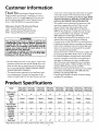
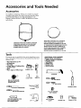
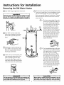

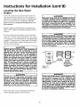
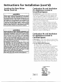
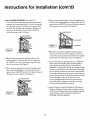
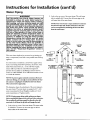
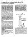
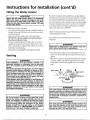
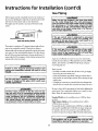
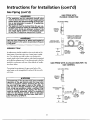
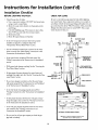
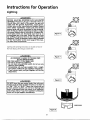
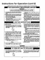
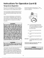
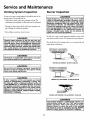

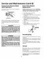

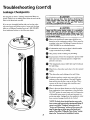


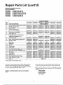
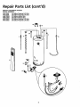

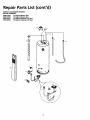
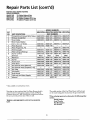
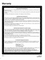
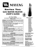
![MA`Y]`AG - Sears Parts Direct](http://vs1.manualzilla.com/store/data/007303854_1-7b2ede6b3b7c67d12ad1099d2b48982d-150x150.png)