1
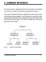
FAX/DATA MODEM
USER’S MANUAL
Notice:
Hayes is a trademark of Microcomputer Products Inc.
Publication Number : ASK9406
Table of Contents
FCC/DOC REQUIREMENTS . . . . . . . . . . . . . . . . . . . . . . . . . . . . i
FCC General Information . . . . . . . . . . . . . . . . . . . . . . . . . . . . i
FCC Notice . . . . . . . . . . . . . . . . . . . . . . . . . . . . . . . . . . . . . . . . . . . . i
DOC Notice . . . . . . . . . . . . . . . . . . . . . . . . ..III
INTRODUCTION . . . . . . . . . . . . . . . . . . . . . . . . . . . . . . . . . . . . . . . . . . . . . . . . . . . . . . . . . . . . . . . . . . . 1
COMMAND REFERENCE . . . . . . . . . . . . . . . . . . . . . . . . . . . . . . . . . . . . . . . . . . . . . . . . . . . . 3
General Command information . . . . . . . . . . . . . . . . . . . . . . ...4
AT Commands . . . . . . . . . . . . . . . . . . . . . . . . . . . . . . . . ...4
Commands Preceded by & . . . . . . . . . . . . . . . . . . . . . 11
Commands Preceded by \ . . . . . . . . . . . . . . . . . . . . . . . . . . . . 17
Commands Preceded by % . . . . . . . . . . . . . . . . . ...23
Commands Preceded by-and ” . . . . . . . . . . . . . . . . ...25
Dial Modifers . . . . . . . . . . . . . . . . . . . . . . . . . . . . . . . 26
Time Independent Escape Sequence (TIES) . . . . . . . . . . . ...29
Result Codes . . . . . . . . . . . . . . . . . . . . . . . . . . . . . . . . ..31
S REGISTER REFERENCE . . . . . . . . . . . . . . . . . . . . . . . . . . . . . . . . . . . . . . . . . . . . . . . . 35
Register Summary . . . . . . . . . . . . . . . . . . . . . . . . . . . . . . . . . . 36
Glossary of the S Registers . . . . . . . . . . . . . . . . . . . 38
TESTING . . . . . . . . . . . . . . . . . . . . . . . . . . . . . . . . . . . . . . . . . . . . . . . . . . . . . . . . . . . . . . . . . . . 53
Local Analog Loopback . . . . . . . . . . . . . . . . . . . . . . . . . . . . . . . . . 53
Local Analog Loopback with Self-Test . . .. . . . . . . . . . . . . 56
Remote Digital Loopback . . . . . . . . . . . . . . . . . . . . . . . . . . . . . 57
Remote Digital Loopback with Self-Test . . .. . . . . . . . . . . 59
Local Digital Loopback . . . . .. . . . . . . . . . . . . . . . . . . . . . . . . 60
Grant or Deny RDL Request from Remote Modem . . . . . 62
TROUBLESHOOTING GUIDE . . . . . . . . . . . . . . . . . . . . . . . . . . . . . . 63
APPLICATION EXAMPLES . . . . . . . . . . . . . . . . . . . . . . . . 67
Dialing a Remote Modem . . . . . . . . . . . . . . . . . . . . . . . . . . . . . . 67
Dial a Stored Number . . . . . . . . . . . . . . . . . . . . . . . . . . . . . . 67
Manual Answer an Incoming Call . . .. . . . . . . . . . . . . . . 68
Auto Answer an Incoming Call . . . . . . . . . . . . . . . . . . . . . . . . . 68
Voice to Data Switching . . . . . . . . . . . . . . . . . . . . . . . . 69
..
... ...
TECHNICAL SPECIFICATIONS . . . . . . . . . . . . . . . . . . . . . . . . . . . . . . . . . . . . . . . . . 71
Features . . . . . . . . .. . . . . . . . . . . . . . . . . . . . . . . . . . . . . . . . . . 71
QUICK REFERENCE . . . . . . . . . . . . . . . . . . . . . . . . . . . . . . . . . . .75
ASCII CODE TABLE . . . . . .. . . . . . . . . . . . . . . . . . . . . . . . . . . . . . . . . . 79
i - FCC/DOC REQUIREMENTS
i.1 FCC General Information
The Federal Communications Commission (FCC) of the United States restricts
specific uses of modems, and places registration responsibilities on both the manufacturer and the individual user:
1. The modem may not be connected to a party line or to a coin operated telephone,
2. The modem manufacturer must make any repairs to the modem to maintain
valid FCC registration.
3. Notification to the telephone company is no longer required prior to connecting registered equipment, but upon request from the telephone company, the
user shall tell the telephone company which line the equipment is connected
to as well as the registration number and ringer equivalence number of the
registered protective circuitry FCC information is printed on a label on the
bottom of the modem.
i.2 FCC Notice
This equipment has been tested and found to comply with the limits for a digital device, pursuant to Subpart B of Part 15 of the FCC rules. These limits are designed
to provide reasonable protection against harmful interference in a residential installation. This equipment generates and uses radio frequency energy and if not ini - FCC/DOC REQUIREMENTS
I
stalled and used the instructions. may cause interference to radio communications.
However, there is no guarantee that interference will not occur in a particular installation, If this equipment does cause harmful interference to radio or television
reception, which can be determined by turning the equipment off and on, the user
is encouraged to try and correct the interference by one or more of the following
measures:
Reorient or relocate the receiving antenna.
Increase the separation between the equipment and receiver.
Connect the equipment into an outlet on a curcuit different from that to
which the receiver is connected.
Consult the dealer or an experienced radio/TV technician for help.
Shielded interconnect cables and a shielded power cord must be employed with
this equipment to insure compliance with the pertinent RF emission limits
governing this device. Changes or modifications not expressly approved by the
manufacturer could void the user’s authority to operate this equipment.
NOTE : The manufacturer is not responsible for any radio or T.V. interference caused by unauthorized modifications to this equipment. Such modifications could void the user’s authority
to operate the equipment.
ii
FCC/DOC REQUIREMENTS - i
i.3 DOC Notice
Notice: The Canadian Department of Communications label identifies certified
equipment. This certification means that the equipment meets certain telecommunications network protective, operational and safety requirements. The Department
does not guarantee the equipment will operate to the user’s satisfaction.
Before installing this equipment, users should ensure that it is permissible to be
connected to the facilities of the local telecommunications company. The equipment must also be installed using an acceptable method of connection, In some
cases, the company’s inside wiring associated with a single line individual service
may be extended by means of a certified connector assembly (telephone extension
cord). The customer should be aware that compliance with the above conditions
may not prevent degradation of service in some situations.
Repairs to certified equipment should be made by an authorized Canadian maintenance facility designated by the supplier. Any repairs or alterations made by the
user to this equipment, or equipment malfunctions. may give the telecommunications company cause to request the user to disconnect the equipment.
Users should ensure for their own protection that the electrical ground connections
of the power utility, telephone lines and internal metallic water pipe System if present, are connected together. This precaution may be particularly important in rural
areas,
i - FCC/DOC REQUIREMENTS
Ill
Caution: Users should not attempt to make such connections themselves, but
should contact the appropriate electric inspection authority. or electrician, as appropriate.
The Load Number (LN) assigned to each terminal device denotes the percentage
or the total load to be connected to a telephone loop which is used by the device, to
prevent overloading. The termination on a loop may” consist of any combination of
devices subject only to the requirement that the total of the Load Numbers of all the
devices does not exceed 100.
iv
FCC/DOC REQUIREMENTS - i
1- INTRODUCTION
Congratulations on your purchase of this outstanding Fax/Data Modem. This manual describes how to operate your new Fax/Data Modem.
Instructions for installing your Fax/Data Modem will be found in the Installation
Manual, while the information in this manual, deals exclusively with the operation
of the modem after it is installed, such as the command set, the internal configuration registers, troubleshooting and testing.
Features :
These Fax/Data Modems combine the features of a 14400 bps data modem and a
14400 bps FAX modem. Your new Fax/Data Modem gives your personal computer the ability to send and receive FAX messages over the telephone line like a
standard FAX machine. Your Fax/Data Modem also allows your PC to communicate with other personal computers, terminals or BBS’s (Bulletin Board Systems)
through the data modem functions,
When used as a data modem your Fax/Data Modem uses the standard AT command
set and is fully compatible with CCITT V.42, V.42bis, V.32bis, V.32, V.22bis,
V.22, V.21, MNP 2-5, Bell 103 and 212A. When used as a Fax/Data Modem it
communicates with all CCITT Group 3 FAX machines and is compatible with
CCIIT V.27ter and V.29, V 17, T.4 and T,30. Switching between DATA mode operation and FAX mode operation of your Fax/Data Modem is done through its
firmware, no hardware settings are required.
1- INTRODUCTION
1
If you are already familiar with the use of a modem and the Hayes AT command
set, this modem will be extremely easy for you to use. Just read the installation procedures in the installation manual and you are ready to begin operation. If you are
new to modem communications, we recommend that you read through this manual
first. If you come across terms that you don’t understand. consult the glossary.
Words in boldface type are command names, commands. or default settings. Carnage returns (Enter) are noted with <CR> or [ENTER]; this does not mean to enter
these characters literally; but instead to press the Enter key.
This manual is written to be used for several models of Fax/Data Modems. Some
of the information in this manual may not apply to your fax/data modem.
2
INTRODUCTION -1
2- COMMAND REFERENCE
This chapter provides an alphabetized reference with examples for all commands
for the modem. The system of commands is depicted below in Figure 2-1.
To use these commands for dialing or configuring the modem, make sure the
communications software package you will be using lets you operate the modem
through its internal commands. If your software permits use of the modem’s internal commands, read this chapter. If not, read your software user’s manual and
ignore the rest of this manual.
Fig. 2-1
System of Commands
2- COMMAND REFERENCE
3
2.1 General Command Information
Except for the A/ command and the TIES escape sequence described in Section 2.4,
all commands must be prefixed with the attention code AT. For instance, the A
command (below) would be entered as: “AT A <CR>”. Without the AT prefix,
the command line cannot be executed. Once entered, AT cannot be deleted with
the Backspace or Delete keys.
More than one command can be placed on a single line and, if desired, separated
with spaces for readability. Once the carriage return (Enter) key is pressed, the
command line is executed. Aline with no carriage return is ignored.
The modem accepts either upper or lower case characters in the command line and
ignores any spaces within or between commands. Typing errors can be corrected
with the Backspace key. Exceptions are noted in the description of specific commands.
A command without any parameter is eqivant to that the parameter 0 is being used,
for example, the command line ATL is equal to ATL0.
2.2 AT Commands
A/
Repeat Last Command
This command re-executes the last ‘AT’ command string stored in the command
4
COMMAND REFERENCE - 2
buffer. The A/ command is the only command not preceded by ‘AT’ and ended by
a carriage return.
Go On-line in Answer Mode
A
This command instincts the modem to go off-hook immediately and then make
a handshake with the remote modem. Handshaking is not available during leased
line operation. This command is useful for manually answering a call or establishing a back-to-back connection with an originate mode modem.
Bn
Select Protocol to 300 bps or 1200 bps
B0
B1
Cn
Selects CC ITT 300 or CC ITT 1200 protocol
once the command line prefix AT has been
entered at the 300 bps or 1200 bps data rate,
Selects BELL 300 or BELL212A protocol once
the command line prefix AT has been entered
at the 300 or 1200 bps data rate. (default)
Carrier Transmit Control
Controls the transmit carrier. The modem is preset to turn carrier on and off as necessary (the C1 option). The signal is on when the modem is calling, or connected to
a remote modem, and is off when it is not. The CO option is NOT valid.
C0
C1
Not permitted; returns ERROR result code
Normal transmit carrier switching. (default)
2 - COMMAND REFERENCE
5
Go On-line in Originate Mode
D
D instructs the modem to go off-hook immediately and automatically dial the number contained in the dial string following D. The dial string may contain any of the
dial modifiers contained in the following section. The D command without a dial
string is usually used to switch from voice conversation to data communication or
to call a remote modem in leased-line operation mode. During this kind of operation. the dial tone monitor should be disabled with the X0, X1, or X3 commands.
Command Echo
En
E0
El
Disables command echo.
Enables command echo. (default)
On-line Echo
Fn
This command is normally used to select whether the modem echoes data back to
the host during on-line data mode. This device set does not support on-line data
mode echo,
F0
F1
Hn
Hang Up
HO
H1
6
Echo enabled. (returns an error message)
Echo disabled. (default)
Goes on-hook. (hangs up)
Goes off-hook. (ready to dial)
COMMAND REFERENCE - 2
In
Identification/Checksum Option
This command causes the modem to send product code and hardware setup information to the DTE.
I0
I1
I2
I3
I4
Report product code. (default)
Firmware version #.
Verify ROM checksum.
Device set name.
Modem configuration.
0= Hayes Escape Sequence.
Bit 0
1 =TIES Escape Sequence,
Bit 1
0= Data/fax/voice without V.42/MNP firmware.
1 =Data/fax/voice with V.42/MN P firmware.
0= Serial host interface,
Bit 2
1 =Parallel host interface.
0=No external Static RAM present.
Bit 3
1 =External Static RAM present,
Bit 4
0=8K x 8 static RAM present. (valid only if bit 3 = 1 )
1 =32K x 8 static RAM present. (valid only if bit 3 = 1)
Bits 5-7 Reserved
Buffer Control
Kn
This command selects whether the modem SRAM is used for voice and fax mode,
K0
K1
SRAM buffer disabled. (default when no SRAM is available)
SRAM buffer enabled. (default when the SRAM is available
on modem board) (default)
2 - COMMAND REFERENCE
7
Control Speaker Volume
Ln
L0
L1
L2
L3
Low volume.
Low volume.
Medium volume. (default)
High speaker volume.
Monitor Speaker On/Off
Mn
M0
M1
M2
M3
Nn
Speaker is always off.
Speaker is off while receiving carrier. (default)
Speaker is always on.
Speaker disabled while dialing or receiving carrier
Select Data Rate Handshake
This command specifies whether the resulting modem-to-modem data rate can be
different than the local DTE-to-modem data rate.
N0
N1
8
When originating or answering, handshake only at
the DTE-to-modem data rate.
When originating or answering, begin handshaking
at the DTE-to-modem data rate. If the remote modem
does not support the local DTE-to-modem data rate.
fall down to the highest compatible data rate. (default)
COMMAND REFERENCE - 2
On
Return to the On-line State
Applies to asynchronous operation only. If the user enters the command mode from
the data mode by issuing the escape sequence, or as a result of ON-to-OFF transition of DTR with the AT&D1 option in effect, the user may return to the data mode
without terminating a call by issuing the ATO command.
O0
O1
P
Causes the modem to return to the data mode. (default)
Enters on-line data mode with a retrain before returning
to on-line data mode.
Set Pulse Dial as Default
Causes the modem to assume that all subsequent dial commands are pulse dialed.
You may omit the “P’ from the dial strings.
Result Code Display
Q
Determines whether the modem sends the result codes to the DTE.
Q0
Q1
Allows the modem to send result codes to the
DTE. (default)
Prohibits the modem from sending result codes
to the DTE.
2 - COMMAND REFERENCE
9
Reading and Writing to S Registers
Sn
Sn?
Sn=x
Reads S Registers:
Reads the contents of the S register specified by ‘n’.
Writing to Registers:
Writes the value of x to the specified S register. All
the registers will return the OK response if x is a legal
value. (n= 0-30, x=0-255)
Set Tone Dial as Default
T
Causes the modem to assume that all subsequent dial commands are tone dial.
Select Word or Digit Result Codes
Vn
Displays. result codes in digital format.
V0
VI
Xn
10
Displays result codes in verbose format. (default)
Select Result Codes
X0
X1
X2
X3
X4(default)
Connect Message
Partial
Full
Full
Full
Full
Dialtone Monitor
Off
Off
On
Off
On
Busy Tone Monitor
Off
Off
Off
On
On
COMMAND REFERENCE - 2
The partial connect message reports CONNECT, the full message reports CONNECT XXXX, where XXXX is the data rate.
Yn
Enables or Disables Long Space Disconnect
Disables Long Space Disconnect. (default)
Enables Long Space Disconnect.
Y0
Y1
Zn
Reset
Zn, which must be placed at the end of the command line, resets the active configuration of the modem to the stored configuration saved in nonvolatile RAM, hanngs
up the modem. and clears the command buffer.
Z0
Resets the modem and loads stored
configuration 0. (default)
Resets the modem and loads stored
configuration 1.
Z1
2.2.a Commands Preceded by &
&Cn
Select DCD Options
&C0
&C1
Maintains an ON status for the Data Carrier
Detect. (DCD)
Uses the actual state of the carrier from the
remote modem for DCD. (default)
2 - COMMAND REFERENCE
11
&Dn
DTR Option
This command controls how the modem responds to DTR, After toggling DTR,
the host should wait 200 ms before modifying the UART registers or sending a
new command to the modem as the modem does not send an ‘OK’ message to
indicate it has performed the requested function.
&D0
&D1
&D2
&D3
Note :
&F
In asynchronous mode (&Q0), the modem
ignores DTR.
The modem switches from data mode to
command mode when an on-to-off transition
of DTR occurs.
An on-to-off transition of DTR causes the
modem to go on-hook (hang-up) and disable
auto-answer mode. Auto-answer mode (S0
is not equal to zero) is enabled when DTR is
turned on. (default)
An on-to-off transition of DTR re-initializes
the modem. The re-initialize procedure
performs a power-up reset, except that the
UART registers are not re-configured,
The modem will not respond to a DTR toggle
in sleep or power down mode (see S-register
S30) It is recommended that a character be
sent to wake up the modem prior to toggling
DTR.
Fetch Factory Configuration
This command loads command and S-register factory defaults into the active configura-
tion, and configures the modem for data mode.
12
COMMAND REFERENCE - 2
Set Guard Tone
&Gn
&G0
&G1
&G2
Guard tone disabled. (default)
550 Hz guard tone enabled.
1800 Hz guard tone enabled.
Auxiliary Relay Control
&Jn
This command is only included for compatibility and performs no function except
to load the S-register.
&J0
&J1
&J0 command. (default)
&J1 command.
&Pn Select Pulse Dialing Make/Break Ratio
&P0
&P1
Sets a 39/61 make/break ratio at 10 pps. (default)
Sets a 33/67 make/break ratio at 10 pps.
&Sn DSR Option
This command controls how the modem treats the DSR signal.
&S0
&S1
DSR circuit always on. (default)
DSR circuit is on during handshaking, off
in test or idle modes. DSR is on when carrier
is lost.
2 - COMMAND REFERENCE
13
&Tn
Testing and Diagnostics (See Chapter 4)
This command is used 10 initiate and terminate loopback tests for testing modem-tomodem and DTE-to-modem data communication integrity.
&T0
&T1
&T3
&T4
&T5
&T6
&T7
&T8
Terminates test in progress. (default)
Local analog Ioopback.
Local digital Ioopback.
Grants RDL request from remote modem.
Denies RDL request from remote modem.
Remote digital Ioopback.
Remote digital Ioopback with self-test.
Local analog Ioopback with self-test.
&U Disable Trellis coding
This command selects whether the modem will transmit and receive modulated
9600 bps carrier with QAM or Trellis encoding for V.32.
Range: n = 0-1
&U0
&U1
&Vn
Enabled. (Trellis modulation with QAM
modulation as a fallback) (default)
Disabled. (QAM modulation only)
View Active Configuration and Stored Profiles
This command causes the modem to send command and S-register configuration
information to the DTE for the following: the active user profile, and one of two
stored user profiles.
14
COMMAND REFERENCE - 2
&V0
&V1
Stored profile 0. (default)
Stored profile 1.
AT&V1
Stored Profile 1:
Telephone Numbers:
&Z0 12345
&Z1 T4444444
&Z2 T12345
&Z3 T 1 (123) 456-7890
2 - COMMAND REFERENCE
15
&Wn
Store the Current Configuration to Nonvolatile RAM
&W0
&W1
&Yn
Select the Default Profile
&Y0
&Y1
&Zn
Writes the current active configuration to
profile 0 in nonvolatile RAM. (default)
Writes the current active configuration to
profile 1 in nonvolatile RAM.
Uses profile 0 on power-up. (default)
Uses profile 1 on power-up.
Store Telephone Numbers (n=0 to3)
&Zn Stores one of four dial strings (including a telephone number) of up to 38 digits in nonvolatile RAM.
For example: to store the telephone number 002852117 to RAM location 1, issue
the following command:
Command: AT&Z1=002852117 <CR>
16
COMMAND REFERENCE - 2
2.2b Commands Preceded by\
\An
Maximum MNP Block Size
Sets maximum block size for MNP connections. Use this command to transmit
smaller blocks of data in a reliable link connection,
\A0
\A1
\A2
\A3
\Bn
Sets maximum block size to 64 characters.
Sets maximum block size to 128 characters.
Sets maximum block size to 192 characters.
Sets maximum block size to 256 characters
(default)
Transmit Break
This command causes the modem to send a break (Attention signal), for a duration
specified by ’n’, to the remote modem. When n = 0, the default break length is used.
n= 0-9
\Cn
Break length in 100 msec.
Set Auto-reliable Buffer (requires a license from Microcom ®
In auto-reliable mode (\N3), this command determines the fallback method and
enables data buffering. The settings for this command are used by the modem
during the V.42 detection phase.
2 - COMMAND REFERENCE
17
\C0
\C1
\C2
\Gn
Modem to Modem Flow Control (XON/XOFF)
\G0
\G1
Disable flow control. (default)
Enable flow control.
Enable/Disable DTE Auto Rate Adjustment
\Jn
\J0
\J1
\Kn
Does not buffer data. (default)
Buffers data for four seconds until 200 characters
have been buffered or SYN character is detected,
then switches to reliable mode. If the buffer fills,
data is passed to the serial port.
DoeS not buffer data. Switches to normal mode
upon receipt of auto-reliable fallback character and
passes it to serial port. This feature is used to allow
non-v.42 modems to connect immediately to a V.42
modem without data loss.
Disable adjustment of DTE speed to match
line speed. (default)
Enable adjustment of DTE speed to match line
speed.
Break Control
Defines what action the modem takes when a break (Attention signal) is sent or
received, as described below.
In Connect State, if reliable mode then transmit break to remote:
Enter command state, but do not send a break.
n = 0,2,4
18
COMMAND REFERENCE - 2
n=1
n=3
n=5
Destructive/expedited,
Non-destructive/expedited.
Non-destructivelnonexpedited.
In Command State, if reliable mode then transmit break to remote:
n = 0,1
Destructive/expedited.
n = 2,3
n = 4,5
Non-destructive/expedited.
Non-destructive/non-expedited.
In Connect State, if direct mode then receive break at serial port:
n = 0,2,4
n = 1,3,5
Immediately send break and enter command state.
Immediately send break through.
In Connect State, receive break at modem port, send to serial port:
n = 0,1
Destructive/expedited.
n = 2,3
n = 4,5
Non-destructive/expedited.
Non-destructive/non-expedited.
Default: 5
\Nn Set Operating Mode
Determines the type of connection attempted by the modem.
\N0
\N1
\N2
Normal Mode - No data compression or error
correction, but uses speed buffering.
Direct Mode - No data compression, error
correction, or speed buffering.
MNP Reliable Mode - The modem attempts
to negotiate an MNP error-correction ‘reliable’
link, hanging up if it fails.
2 - COMMAND REFERENCE
19
\N3
\N4
V.42 Auto-reliable Mode * - If V.42 detection
is enabled (-Jn), a LAPM or MNP link can be
detected and negotiated, otherwise only LAPM
will be attempted. If configured for -J0 and a
protocol connection is not made, the modem
will hang up. If configured for -J1 and a protocol
connection is not made, the modem will fall back
to speed buffering mode. (default)
V.42 Reliable - The modem attempts to negotiate
LAPM error correction, hanging up if it fails.
NOTE: 300 bps does not support synchronous operation. The mode will
automatically fall back to MNP asynchronous operation.
\O
Originate Reliable Link
in normal mode (\N0), the modem will attempt to originate an MNP link, regardless
of whether the modem originated or answered the telephone call (physical connection). The remote modem must answer the MNP link request for the link to be
established (refer to the \U command).
\Qn
Set Serial Port Flow Control
This command specifies the DTE-to-modem flow control. Software flow control uses
the XOFF (13 hex) and XON (11 hex) characters to stop and start data transmission, respectively, both to and from the DTE. Unidirectional hardware flow control
uses the CTS control line to stop/start data from the DTE only, while bidirectional
hardware flow control also uses the RTS control to stop/start data from the modem.
20
COMMAND REFERENCE - 2
\Q0
\Q1
\Q2
\Q3
\Tn
Disables flow control.
XON/XOFF software flow control.
Unidirectional hardware flow control.
Bidirectional hardware flow controll. (default)
Set Inactivity Timer
During a normal or reliable connection, if no data is sent or received within the
inactivity time period, the link will be disconnected. The default of zero disables
this feature.
n=0-90
\T0
\U
Lenth in minutes.
Disables inactivity timer. (default)
Accept Auto-reliable Link
in normal mode (\N0), the modem attempts to answer an MNP link request regardless of
whether the modem originated or answered the telephone call (physical connection). The remote modem must originate the MNP link request for the link to be
established (refer to the ‘\O’ command).
\Vn
Modify Result Code Form
This command specifies which modem response codes are supported.
\V0
Enables codes defined by ATV
command. (default)
2 - COMMAND REFERENCE
21
\V1
\V2
\Xn
Enables modified MN P codes.
Enables extended V.42 codes.
Set XON/XOFF Passthrough
If software flow control is enabled (\Ql), this command defines whether the XON
(11 hex) and XOFF (13 hex) characters received from the DTE are sent to the
remote modem. In addition, if the modem port flow control is enabled (\G1) in
normal mode, the command specifies whether the XON and XOFF characters
received from remote modem are sent to the DTE. In both cases, flow control
operation is not affected.
\X0
\X1
\Y
Processes flow control characters. (default)
Processes flow control characters and
passes them through to the local or remote
so they can process the characters.
Switch to Reliable Mode
in normal mode (\N0), the modem attempts to originate or answer an MNP link
request, depending on whether the modem originated or answered the physical
connection, respectively. The remote modem must attempt to answer/originate the
MNP link for the link to be established.
22
COMMAND REFERENCE - 2
\Z
Switch to Normal Mode
During an MNP link, the modem will disconnect the link (exit error correction/
data compression) and change to narmal mode, without disconnecting the modemto-modem connection.
2.2.c Commands Preceded by %
%An
Set Auto-reliable Fallback Character
In auto-reliable mode (\N3), with auto-reliable fallback character enabled (\C2),
receipt of the fallback character from the line during the V.42 detection phase will
cause to modem to switch to normal mode. This allows a remote user with a nonV.42 modem to connect immediately with a V.42 modem, A space or carriage
return is usually chosen for the fallback character.
n=0-127 (ASCII character)
%Cn
MNP 5 Data Compression Control
This command controls whether the data sent during the MNP frames is compressed using MNP Class 5 compression standard. MNP 5 data compression can
improve throughput by as much as 150%
%C0
%C1
No compression.
MNP Class 5 compression. (default)
2 - COMMAND REFERENCE
23
%En
Auto-retrain Control (V.22 bis and V.32 bis only)
This command controls whether the modem will automatically initiate a modem
retrain whenever the Received Data signal quality falls below a threshold that may
affect data reliability. The value for ‘n’ is stored in the NVRAM, but it is not
displayed by the ‘AT&Vn’ command.
%E0
%E1
%Gn
Disabled.
Enabled. (default)
Auto Fallforward/fallback Enable (V.32 bis only)
This command selects whether the modem will automatically initiate a change to
a higher speed or lower speed depending on received signal quality (i.e. Rate Negotiation). The modem always responds to any rate change initiated by the remote
modem.
%G0
%G1
%Q
Disabled. (default)
Enabled.
Line Signal Quality
This command returns the higher order byte of the EQM value, This information
indicates the quality of the telephone line signal. Note that this value will be different for different DAAs.
Range:
0-7
24
0-255
No Retrain
COMMAND REFERENCE - 2
8-255
Modem performs a Retrain. (i.e., if configured for %E1)
2.2.d Commands Preceded by - and “
-Cn
Generate Data Modem Calling Tone
This command allows the DTE to select whether the modem will send 1300 Hz
calling tone when originating a Data Modem connection.
-C0
-C1
-Jn
Calling tone disabled. (default)
Calling tone enabled.
Set V.42 Detect Phase
In V.42 modes (\N3, \N4), this command specifies whether the modem will detect
V.42, MNP, or no error-correcting protocols from the remote modem and change
to the appropriate mode. Otherwise, only LAPM will be attempted.
“Hn
-J0
Disables the V.42 detect phase.
-J1
Enables the V.42 detect phase. (default)
V.42 bis Compression Control
This command specifies whether the data in the LAPM frames are compressed
using the V.42 bis data compression, which can improve throughput by as much as
400%. Compression can be negotiated to operate in only one direction, or in both
directions.
2 - COMMAND REFERENCE
25
“H0
“H1
“H2
“H3
“On
Disables V.42 bis.
Enables V.42 bis only when transmitting data.
Enables V.42 bis only when receiving data.
Enables V.42 bis for both transmitting and
receiving data. (default)
V.42 bis String Length
This command specifies the maximum number of characters that can be compressed into one V.42 bis code word. The default value of 16 optimizes throughput
for most file types.
n=6-250=Number of characters
2.3
Dial Modifers
This section describes all of the dial modifiers which are used in dial strings.
@
Wait for Quiet Answer
Cause the modem to wait for specified amount of time (S-register
S7) followed by 5 seconds of silence before processing the next
dial modifier.
26
COMMAND REFERENCE - 2
,
Pause
“,”, placed anywhere in the dial string, tells the modem to pause
for the number of seconds specified by S-register S8 before processing the rest of the dial string.
!
Initiate a Hookflash
“!”, placed anywhere in the dial string, tells the modem to initiate a hookflash, which means to hang up for 0.75 seconds and
then go off-hook again before processing the rest of the dial
string. This modifier allows access to PBX features like call transferring.
-( )
Ignored by Modem
These four characters are ignored by the modem, but space may be
included in the dial string for separating area codes and numbers.
Return to Idle State
Causes the modem to enter on-line command mode without initiating
a data modem handshake (used for phone directory auto-dialers).
2 - COMMAND REFERENCE
27
P
Pulse Dialing
P, placed ahead of a number, tells the modem to dial a number
using pulse dialing.
R
Reverse Originate Mode to Answer Mode
R, which can only be placed at the end of the dial string, tells the
modem to change from the originating mode to the answer mode
once it dials all the digits before the R. This modifier is used to
call an originate-only modem,
S
Dial a Stored Number
S is used to dial one of four numbers stored in nonvolatile memory. For example, instead of entering a dial string, you can use
this command:
Command: ATDTS=1<CR>
T
Tone Dialing
T, placed ahead of a number, tells the modem to dial a number using
touchtone dialing,
28
COMMAND REFERENCE - 2
W
Wait for Dialtone
Causes the modem to look for dial tone for a specified amount of
time. If dial tone or the amount of time specified by the S-register
S6 times-out, the modem will then process the next command in the
dial string. If a busy signal is detected, the modem will respond
back to the DTE with a busy response code, and then go into offline command mode.
2.4 Time Independent Escape Sequence (TIES)
The Time Independent Escape Sequence (TIES) has been developed by a
group of modem manufacturers as an alternative to the Hayes Escape Sequence. TIES has been designed to work with existing communication software written for the Hayes Escape Sequence.
The escape sequence is sent by the host (DTE) to return the modem to
command state while in the on-line data state (connected to another modem) or diagnostic mode (&Tn commands).
The DTE implements the escape sequence by sending the escape character three times, followed by a valid ‘AT’ command and the contents of S3
(typically a <CR>). Upon detecting the three consecutive escape characters, the modem changes to a TIES command mode, and starts an internal
Escape Prompt Delay timer (EPD) - with the time limit as defined by S12.
If the EPD timer times out, the modem sends an ‘OK’ message to the DTE
2 - COMMAND REFERENCE
29
and then waits indefinitely for an incoming valid ‘AT’ command string from
the DTE.
If the next character received by the modem is not an ‘A’ or ‘a’, then the modem
returns to data mode and sends a ‘CONNECT message back to the DTE.
If the modem receives an ‘A’ or ‘a’, the modem disables the EPD timer (if it
has not time out) and sends the character to the remote modem. The modem then stores any received data from the DTE into the modem internal
command buffer and sends the data to the remote modem. Upon detecting
a <CR> or receiving Up to 39 data characters, the modem then determines
if a valid ‘AT’ command has been received and then processes the valid
commands. If a non-’AT’ command string or an invalid command string has
been received then the modem will remain in data mode. If a valid ‘AT’
command has been received, then the modem changes to command mode
and sends an ‘OK message. After sending the ‘OK message, the modem
will echo back any received data from the DTE while in command mode.
While in TIES command mode, the modem ignores certain characters that
may cause the modem to incorrectly decide that an incoming ‘AT’ string is
invalid. The ignore character are <LF>, <space>, and <CR> (<CR> is ignored only when S3 is not equal to <CR>). Not all ‘AT’ commands are supported during TIES command mode. The following is a list of supported
commands:
E, H, M, O, Q, S, V, X, Z, and ampersand’&’ commands
The escape character is determined by the value stored in S-register S2,
and is typically a + character. An example of the TIES Escape Sequence is
30
COMMAND REFERENCE - 2
provided below.
Format:
<char1> <char2> <char3> <AT command> <contents of S3>
char1=char2=char3=escape character (S2)
e.g.,
DTE: +++AT<CR>
DCE: OK
NOTE:
TIES requires that the three-character escape sequence be
contiguous and not repeated. The character immediately preceding the first character of the three-character sequence cannot
be the same as the escape character. Therefore, ‘+++AT<CR>’
is valid, but ‘++++ AT<CR>’ is not.
2.5 Result Codes
Basic Response Codes (\V0)
Numeric Code
Verbose Code
0
1
2
3
4
5
6
7
2 - COMMAND REFERENCE
OK
CONNECT
RING
NO CARRIER
ERROR
CONNECT 1200
NO DIAL TONE
BUSY
31
Numeric Code
8
Verbose Code
10
NO ANSWER
CONNECT 2400
11
12
14
16
17
CONNECT 4800
CONNECT 7200
CONNECT 9600
CONNECT 12000
CONNECT 14432
Modified Response Codes (\V1)
Numeric Code
Verbose Code
22
24
25
26
CONNECT
CONNECT
CONNECT
CONNECT
27
CONNECT 7200/REL
28
29
30
CONNECT 9600/REL
CONNECT 12000/REL
CONNECT 14400/REL
300/REL
1200/REL
2400/REL
4800/REL
V.42 Extended Response Codes (\V2)
Numeric Code
Verbose Code
32
34
35
32
CONNECT 300/REL-MNP
CONNECT 1200/REL-MNP
CONNECT 2400/REL-MNP
COMMAND REFERENCE - 2
Numeric Code
Verbose Code
36
37
38
39
40
42
44
45
46
47
48
49
50
54
55
56
57
58
59
60
CONNECT 4800/REL-MNP
CONNECT 7200/REL-MNP
CONNECT 9600/REL-MNP
CONNECT 12000/REL-MNP
CONNECT 14400/REL-MNP
CONNECT 300/REL-MNP 5
CONNECT 1200/REL-MNP 5
CONNECT 2400/REL-MNP 5
CONNECT 4800/REL-MNP 5
CONNECT 7200/REL-MNP 5
CONNECT 9600/REL-MNP 5
CONNECT 12000/REL-MNP 5
CONNECT 14400/REL-MNP 5
CONNECT 1200/REL-LAPM
CONNECT 2400/REL-LAPM
CONNECT 4800/REL-LAPM
CONNECT 7200/REL-LAPM
CONNECT 9600/REL-LAPM
CONNECT 12000/REL-LAPM
CONNECT 14400/REL-LAPM
64
65
66
67
68
69
70
CONNECT 1200/REL-LAPM V.42 BIS
CONNECT 2400/REL-LAPM V.42 BIS
CONNECT 4600/REL-LAPM V.42 BIS
CONNECT 7200/REL-LAPM V.42 BIS
CONNECT 9600/REL-LAPM V.42 BIS
CONNECT 12000/REL-LAPM V.42 BIS
CONNECT 14400/REL-LAPM V.42 BIS
2 - COMMAND REFERENCE
33
3 - S REGISTER REFERENCE
Your modem has status registers. These registers are memory locations inside your
modem which control your modem’s operation. You usually do not have to worry
about setting any register because the default values work for most applications.
The S registers are summarized in Fig. 3-1, along with their default values. Registers denoted with an “*” may be stored in one of the two user profiles by entering
the &Wn command, One of these profiles may be loaded at any time by using the
Zn command.
The factory default values are stored in ROM and are loaded into the active configuration at power-up or by the Zn command. In addition, the designated default
profile is subsequently loaded, and may change some of the factory default values.
The designated default profile can be changed by entering the &Yn command.
where ‘n’ is one of the two possible user profiles. The factory defaults can be
loaded at any time by entering the &F command.
3 - S REGISTER REFERENCE
35
3.1 Register Summary
The following chart summarizes your modem’s registers:
Command
S0
*
S1
S2
*
S3
S4
S5
S6
*
S7
*
S8
*
S9
*
S10 *
S11 *
S12 *
S13
S14 *
S15
S16 *
S17
S18 *
S19
S20
36
S-Registers
Default Type Function
R/W No. of Rings to auto-answer on
0
R/W Ring count
0
43
R/W Escape character
13
R/W Carriage return character
10
RAN Line feed character
R/VV Backspace character
8
R/W Wait before dialing
2
60
R/W Wait for carrier
2
R/W Pause time for dial modifier
6
R/W Carrier recovery time
14
R/W Lost carrier hang up delay
95
R/W DTMF dialing speed
50
R/W Guard time
Reserved
none
R
Bit-mapped options
none
Reserved
none
Modem test options
R
none
Reserved
none
0
R/W Modem test timer
Reserved
none
Reserved
none
-
S REGISTER REFERENCE - 3
S21
S22
S23
S24
S25
S26
S27
S30
S37
S90
S108
S109
NOTE:
*
*
*
none
none
none
none
*
*
*
*
*
*
*
*
(*)
(-)
5
1
none
10
0
0
1
62
R Bit-mapped options
R
Bit-mapped options
R Bit-mapped options
Reserved
R/W Detect DTR change
R/W RTS-to-CTS deIay interval
R Bit-mapped options
R/W Sleep mode timer
R/W Maximum line speed attempted
R/W Disconnect Inactivity timer
R/W Retrain signal quality selector
R/W Line speeds permitted
Value Saved in NVRAM (R)
Read-only register
(R/W) Read/write register
Reserved register
3-S REGISTER REFERENCE
37
3.2 Glossary of the S Registers
S0
Number of Rings to Auto-Answer On
Assigning S0 a value from 1 to 255 configures the modem for
auto-answer mode, The modem will automatically go off-hook
and initiate a data-mode-answer mode handshake after detecting
the specified number of rings,
Range:
n=0
n = 1-255
S1
0-255 rings
Auto-answer mode disabled.
Auto-answer mode enabled.
Ring Count
of ring signals detected by the modem. This
register is cleared to zero if no ring signals are detected within an
eight-second time interval.
Reports the number
Range: 0-255 rings
Default: 0 rings
S2
Escape Character
S2 specifies ASCII value for the TIES escape character. The factory
38
S REGISTER REFERENCE - 3
defaut is ‘+’ or ASCII decimal 43. The escape character may range
between 0-127. Any value over 127 will disable the escape sequence.
Range: 0-127
Default: 43 (’+’)
S3
Carriage Return Character
S3 specifies the ‘AT’ command string terminator and modem response code terminator. The factory default is a <CR> or carriage return (ASCII decimal 13).
Range: 0-127
Default: 13 (carriage return)
S4
Line Feed Character
S4 specifies the line feed character. The line feed character is
used for verbose (text) modem result codes.
Range: 0-127
Default: 10 (line feed)
3- S REGISTER REFERENCE
39
S5
Backspace Character
S5 specifies the backspace character that is used to delete the
last-entered character. After receiving a backspace character, the
modem sends three characters to the DTE: a backspace character, a space character, and then another backspace character.
Range: 0-32, 127
Default: 8 (BS)
S6
Wait Before Blind Dialing
S6 specifies the amount of time after the modem goes off-hook
before the modem starts dialing the first telephone number. The
modem waits for at least 2 seconds, even if S6 is set for a value
less than 2, before dialing the first number. S6 is only used for
result code type commands X0, X1, X3 (i.e., blind dialing result
code types). The ‘W’ (wait for dial tone) dial modifier causes the
modem to ignore the contents of S6. Result code types X2 and
X4 enable dial-tone detection, but never use S6.
Range: 2-255 seconds
Default: 2 seconds
S7
Wait for Carrier/Dial tone
S7 specifies the amount of time that the modem waits to detect the
40
S REGISTER REFERENCE - 3
remote modem carrier after dialing the telephone number. If the
remote modem carrier is not detected within the S7 time limit,
the modem will hang-up and send a NO CARRIER response code
to the DTE. If the remote modem carrier is detected, the modem
goes into on-line data mode and sends a CONNECT message to
the DTE.
S7 also specifies the time duration for the ‘W' (wait for dial tone)
dial modifier.
Range: 1-255 seconds
Default: 60 seconds
S8
Pause Time for Dial Modifier
S8 specifies the amount of time that the modem will pause during
the dialing process each time the ‘,’ dial modifier is detected in
the dialing string,
Range: 0-255 seconds
Default: 2 seconds
S9
Carrier Detect Response Time
S9 specifies how long the remote modem carrier must be present
on the telephone line before the modem will detect it and turns on
DCD, The greater the time duration, the less likely that a false
3-S REGISTER REFERENCE
41
carrier detection will occur due to noise on the telephone line.
Range: 1-255 (1/10 of a second)
Default: 6 (equals 0.6 seconds)
S10
Lost Carrier Hang Up Delay
S10 specifies amount of time the modem waits before hanging
up after the loss of the remote modem carrier. This delay allows
for the temporary loss of the remote modem carrier without causing the local modem to hang up. When set to 255, the modem
will not disconnect upon loss of the remote modem carrier.
Range: 1-255 (1/10 of a second)
Default: 14 (equals 0.6 seconds)
S11
DTMF(Touch-tone) Dialing Speed
S11 determines the duration and spacing of tones for Dual Tone
Multifrequency (DTMF) dialing. This value has no effect on pulse
dialing.
Range: 50-255 milliseconds
Default: 95 milliseconds
42
S REGISTER REFERENCE - 3
S12
Guard Time
S12 is used to specify guard and detect times used for the
TIES Escape Sequences.
For the TIES Escape Sequence, S12 specifies the maximum time
limit after receiving the three escape characters and no other
characters before sending an OK message to the DTE.
Range: 0-255 (1/50 of a second)
Default: 50 (equals 1 second)
S13
Reserved
S14
Bit Mapped Options
Bit
Bit 0
Bit 1
Bit 2
Bit 3
Bit 4
Bit 5
Bit 6
Value Description
0
1
0
1
0
1
0
1
Reserved
E0 is selected.
El is selected. (default)
Q0 is selected. (default)
Q1 is selected.
V0 is selected.
V1 is selected. (default)
Reserved
T (tone) dial is selected.
P (pulse) dial is selected. (default)
Reserved
3 - S REGISTER REFERENCE
43
Bit
Value
Bit 7
0
1
Description
Answer.
Originate. (default)
S15
Reserved
S16
Modem Test Options
Bit
Bit 0
Bit 1
Bit 2
Bit 3
Bit 4
Bit 5
Value Description
0
1
0
0
1
0
1
0
1
0
1
Bit 6
Bit 7
44
0
1
0
Local analog Ioopback disabled. (default)
Local analog Ioopback enabled. (&T1)
Reserved.
Local digital Ioopback disabled. (default)
Local digital Ioopback enabled. (&T3)
Remote digital Ioopback off. (default)
Remote digital Ioopback in progress. (&T6)
RDL not active. (default)
RDL request from distant end is in service.
Remote digital Ioopback with self-test disabled.
(default)
Remote digital Ioopback with self-test enabled.
(&T7)
Analog Ioopback with self-test disabled. (default)
Analog Ioopback with self-test enabled. (&T8)
Reserved.
S REGISTER REFERENCE - 3
S17
Reserved
S18
Modem Test Timer
S18 specifies the amount of time that the modem will conduct
one of the Ioopback tests (&Tn). After timing out, the modem
returns back to command mode. Setting S18 to zero disables the
modem test timer; the Ioopback test must be terminated by issuing
the appropriate escape sequence followed by an ‘AT&T0’ or ‘ATH’.
Range: 0-255 seconds
Default: 0 second
S19
Reserved
S20
Reserved
S21
Bit Mapped Options
Bit
Bit 0
Bit 1
Bit 2
Value
0
1
0
1
Description
&J0 is selected. (default)
&J1 is selected.
Reserved.
&R0 is selected. (default)
&R1 is selected.
3 - S REGISTER REFERENCE
45
Bit
Value
Bits 4-3 00
01
10
11
0
1
0
1
0
1
Bit 5
Bit 6
Bit 7
S22
Bit Mapped Options
Bit
Value
Bits
1-0
Bits
3-2
Bits 6-4
46
&D0 is selected,
&D1 is selected.
&D2 is selected. (default)
&D3 is selected.
&C0 is selected.
&C1 is selected. (default)
&S0 is selected. (default)
&S1 is selected.
Y0 is selected. (default)
Y1 is selected,
00
01
10
11
00
01
10
11
000
001
010
011
100
101
110
111
Description
Reserved.
L1 is selected,
L2 is selected. (default)
L3 is selected.
M0 is selected.
M1 is selected. (default)
M2 is selected.
M3 is selected.
X0 is selected.
Reserved.
Reserved.
Reserved.
X1 is selected.
X2 is selected.
X3 is selected.
X4 is selected. (default)
S REGISTER REFERENCE - 3
Bit
Value Description
Bit 7
0
1
S23
Bit Mapped Options
Bit
Bit 0
Value
0
1
000
Bit 3,2,1
001
010
011
100
101
110
111
Bit 5,4 00
01
10
11
Bit 7,6 00
01
10
11
S24
&P0 is selected. (default)
&P1 is selected.
Description
&T5 is selected.
&T4 is selected. (default)
0-300 bps communications rate.
1200 bps.
2400 bps.
4800 bps.
7200 bps.
9600 bps.
19.2 Kbps.
38.4 kbps.
Even parity. (default)
Space parity/no parity.
Odd parity,
Mark.
&G0 is selected. (default)
&G1 is selected.
&G2 is selected,
Reserved.
Reserved
3 - S REGISTER REFERENCE
47
S25
Detect DTR Change
S25 defines the minimum amount of time that DTR has to remain
off (i.e., on-to-off-to-on transitions) before the modem will perform
the function specified by ‘& Dn’command. A change in DTR that
persists for a shorter time than the valued specified in S25 is ignored by the modem (see ‘&Dn’ command).
Range: 0-255 (1/100 of a second)
Default: 5
S26
RTS to CTS Delay Interval
S26 is only used for synchronous operation. This register, when
the modem is configured for &R0, specifies the time delay between an off-to-on transition on RTS and turning CTS on.
Range: 0-255 (1/100 of a second)
Default: 1 (is equal to second)
S27
Bit Mapped Options
Bit
Bit 3,1,0
48
Value
000
001
010
011
Description
&Q0 is selected. (default)
&Q1 is selected.
&Q2 is selected,
&Q3 is selected.
S REGISTER REFERENCE - 3
Bit
Value
Description
Bit 3,1,0
100
101
110
111
0
1
00
01
10
11
0
1
&Q4 is selected.
Not used.
Not used.
Not used.
&L0 is selected. (default)
&L1 is selected.
&X0 is selected. (default)
&X1 is selected,
&X2 is selected.
Reserved.
B0 is selected.
B1 is selected. (default)
Reserved.
Bit 2
Bit
5,4
Bit 6
Bit 7
S30 Sleep Mode Timer
S30 determines when the modem enters sleep or powerdown mode.
When enabled (S30
0), the DSµP will enter sleep mode whenever
the modem has been inactive for a user-programmable time delay
(S30). The modem is considered to be in an inactive state when:
1) No internal processing is being performed;
2) There is no activity between the host and the modem within
a specified time period;
3) The modem is off-line.
The modem exits sleep modem whenever the host reads or writes
to the modem, or a ring signal is detected.
3 - S REGISTER REFERENCE
49
Sleep mode is disabled by setting S30 to a ‘0’.
Range: 0-90 seconds
S37
Maximum Line Speed Attempted
This S-register selects the maximum line speed allowable (i.e.,
the modem will attempt to connect at this speed or fallback to a
lower speed). Note that S37 has no effect during V.32 bis retraining/rate negotiation,
Range: n=0-11
n=0
n=1
n=2
n=3
n=4
n=5
n=6
n=7
n=8
n=9
n=10
n=11
50
DTE rate
Reserved
Reserved
300
Reserved
1200
2400
4800
7200
9600
12000
14400
S REGISTER REFERENCE - 3
S90
Disconnect Inactivity Timer
This S-register sets the length of time, in minutes, that the modem
will stay on-line /off-hook before disconnecting when no data is trans
mitted or received. In data and fax modes, any data transmitted or
received between the DTE-DCE interface will reset the timer. In
all other modes except Telephone-emulation mode, any data
transmitted will reset the timer. In Telephone-emulation mode,S90
is ignored (i. e., the modem will not automatically hangup the line
after a given time delay).
Range: n= 0-255 minutes
n=0
S108
Disabled
Retrain Signal Quality Selector
This S-register selects when the modem should perform a retrain.
Range: n= 0-3
n=0
n=1
n=2
n=3
Never retrain
Low Quality - retrain after a large number of data errors
Medium Quality - retrain after a number of data errors
High Quality - retrain after a few data errors
Default: V.32
V.32 bis
3 - S REGISTER REFERENCE
n=1
n=2
51
S109
Line Speeds Permitted
This bit mapped S-register selects all permitted line speeds. If
the speed bit is set to a ‘1’, then the modern is permitted to connect at
the specified speed. If the speed bit is set to a ‘0’, then the modem
will never connect at the specified speed.
Bit 0
Bit 1
Bit 2
Bit 3
Bit 4
Bit 5
Bit 6-7
Reserved
4800
7200
9600
12000
14400
Reserved
Default: V.32
V.32 bis
52
S109=10
S109=62
Bit 2, 4, and 5 not supported.
S REGISTER REFERENCE - 3
4 - TESTING
The modem provides five testing features to identify fault location when transmission
quality is not good: local digital Ioopback, local analog loop back, local analog Ioopback
with self-test, remote digital loopback, and remote digital loopback with self-test.
These tests are initiated with the &Tn command described in Chapter 2.
4.1 Local Analog Loopback
The local analog loopback test checks the integrity of the local computer or terminal
and the local modem. During the test. the local modem internally loops data sent
from the local computer or terminal back to the same computer or terminal as
shown in Figure 4-1. During the test, data is not transmitted to the remote modem.
If characters are looped correctly during this test, both the modem and the local
computer or terminal are functioning correctly, If incorrect characters appear on
the screen, either the local computer or terminal or the local modem is in error.
To perform a local analog loopback, put the local modem in the command state.
If it is on-line, issue the escape command + + +, to return to the command state.
4 - TESTING
53
Fig. 4-1 Data Path for Local Analog Loopback
Example 1 - Test timer disabled
Command:
AT/N1 <CR>
ATS18=0&Tl <CR>
Result:
cursor shifts down one line
Test message:
THE QUICK BROWN FOX JUMPS OVER THE
LAZY DOG 1234567890
Escape:
+++
(return to the on-line command state)
OK
Result
54
code:
Command:
AT&T0 <CR> (end the test)
Result code:
OK
TESTING - 4
Here, the test timer is disabled and the modem sets up an internal analog loop as
shown in Figure 4-1. When the loopback is established, the modem goes on-line
and the test message (any character you type) is looped back on the screen for verification. Finally, +++ returns the modem to the command state and &T0 ends the
test and breaks the internal analog loop.
The following command sequence is the same as the previous one except that the
test timer is set to 60 seconds. At the end of the test time, the timer expires, the
test ends, and the test result is reported.
Example 2 - Test timer enabled
Command:
AT/N1<CR>
ATS18=60&T1 <CR>
Result:
cursor shifts down one line
Test message:
THE QUICK BROWN FOX JUMPS OVER
THE LAZY DOG 1234567890
Escape:
OK
4 - TESTING
55
4.2 Local Analog Loopback with Self-Test
The local analog loopback with self-test checks the integrity of the local modem.
In this test, an internally generated data pattern of alternate binary ones and zeros
(reversals) at the selected bit rate is looped through the internal analog loop inside
the local modem to an internal error counter as shown in Figure 4-2. An error count of 255
indicates that 255 or more errors were detected.
Example - The test timer is disabled and 12 errors are found during the test
Fig. 4-2 Local Analog Loopback with Self-test
56
Command:
AT\N1<CR>
ATS18=0&T8<CR>
Result:
cursor shifts down one line (test starts)
TESTING - 4
Command:
AT&T0< CR> (ends the test)
Test result:
012 (12 errors were found during the test)
Result code:
OK
4.3 Remote Digital Loopback
Fig. 4-3 Data Path for Remote Digital Loopback
The remote digital loopback test cheeks the integrity of the local computer or terminal, the
local modem, the telephone line, and the remote modem, During the test message
is sent from the local computer through the local modem to the remote
modem and looped through the remote digital loop inside the remote modem back to
an internal error counter as shown in Figure 4-3.
During this test, data is not transmitted to the remote computer or terminal. If
characters are looped correctly, the local computer or terminal, the local modem,
4 - TESTING
57
the telephone line and the remote modem are all operating correctly.
To start a remote digital loopback, first make sure the modem is on-line with a
remote modem.
Below, in the second command line, the timer is inactive, in the third command
line, the test timer is activated for 60 seconds.
Command:
58
AT\N1<CR>
ATS18=0&T6<CR>
ATS18=60&T6<CR>
TESTING - 4
4.4 Remote Digital Loopback with Self-Test
The remote digital loopback with self-test checks the integrity of the local modem,
telephone line, and the remote modem. In this test the modem activates an internal
test pattern generator. A test data stream is sent over the telephone line to the remote
modem and looped through a remote digital loop to an internal error counter in the
local modem as shown in Figure 4-4.
Fig. 4-4 Remote Digital Loopback with Self-test
To perform the remote digital loopback with self-test, first make sure that the modem
is on-line to the remote modem. The modem can be either in the originating mode or
in the answer mode.
Example - The test timer is set and the test is performed with no errors
4 - TESTING
59
Escape command
+++
(return the modem to the on-line command state)
Result code:
OK
Command:
AT\N1 <CR>
ATS18=60&T3<CR>
Result:
cursor shifts down one line
(test starts)
Test result:
000
(timer expires and no errors were found)
Result code:
OK
4.5 Local Digital Loopback
Local digital loopback checks the integrity of the remote modem and the phone line
if the remote user suspects either to be the cause of transmission errors.
During this test the modem loops data internally sent from the remote modem back
to the remote modem as shown in Figure 4-5, During the test, data is not received
by the local personal computer. Local digital loopback is useful when a remote modem is
unable to request a remote digital loopback.
60
TESTING - 4
Fig. 4-5 Data Path for Local Digital Loopback
To start a local logical loopback first make sure that the modem is on-line with a
remote modem. The modem can be in either the originating or answer modem.
Example - To implement a local digital loopback test
Escape:
+++
Result Code: OK
Command:
4 - TESTING
AT\N1 <CR>
ATS18= 0 &T3<CR>
61
Result Code: OK
This command sequence returns the modem to the command state but does not
break the established connection. It then disables the test timer and sets up an
internal digital loop inside the modem. End the test when you confirm that the
remote user has already finished by issuing:
Command:
AT&T0<CR>
Result Code: OK
4.6 Grant or Deny RDL Request from Remote Modem
The modem can grant a request from the remote modem for a remote digital loopback test
with the &T4 command (default). Once the modem grants the request, it sets
up an internal digital loop as in Figure 4-5. When the remote modem terminates
the remote digital loopback test by sending a termination sequence. The modem
breaks the external digital loop.
The modem can deny the request for a remote digital loopback test with the &T5
command. To set &T5 as the default. issue:
Command:
AT\N1 <CR>
AT&T5&W<CR>
Result Code: OK
62
TESTING - 4
5 - TROUBLESHOOTING GUIDE
This chapter describes common problems in the installation, configuration and
regular usage of your Fax/Data Modem. To test the Fax/Data Modem, a communication software package is needed and the package must include a mode that allows
you to operate your Fax/Data Modem by directly issuing internal commands to the
modem.
Follow the procedures in the following sections to resolve these common problems:
No Response From Your Modem
1.
If you are using the internal add-on card modems, make sure that the COM
port address you have set your modem to corresponds to the appropriate selection in the communications software which you are using.
2.
Issue the ATZ command to reset your modem. The returned result code
should be “0” or “OK’ depending on what communications program you
are using. Your modem is OK if you get one of these responses. If there is no
response after issuing the ATZ<CR>, continue to the next step.
3.
Check if there are any other interface cards in your computer that use the
same COM port address as your modem. If so, you must set your modem to
another COM port address. (Keep in mind that on most systems, only two
COM ports are available. One of them must be used as either 1 or 3, while
the other must be used as 2 or 4.) For example, if a mouse is set to COM 1,
5 - TROUBLESHOOTING GUIDE
63
your modem should be set to COM2 or COM4. Continue to the next step if
the COM port address is OK.
4. Issue the command: AT&F&W <CR>, if a “0” or “OK result code is displayed on the screen, your modem is OK. Otherwise, contact your dealer for
assistance.
Your Modem Does Not Dial Out
Make sure that your modem responds normally as described in
section 4.1. If you can communicate through the keyboard, check
whether the modem is properly connected to the phone line.
Your Modem Does Not Connect After It Has Dialed a Phone Number
The problem may have several causes. The phone line may be
too noisy or the telephone cord may be poor. Try the line with a
regular phone. Also the remote modem may not recognize your
modem’s baud rate.
Your Can’t Transmit After You Have Connected to the Remote Modem
In this case, check the communication parameters of the remote
modem, then configure your software to the same number of data
bits, stop bit, and parity.
64
TROUBLESHOOTING GUIDE - 5
Fig. 5-1 Troubleshooting Flowchart
5- TROUBLESHOOTING GUIDE
65
Finding the Source of Transmission Errors
A failure in modem communication is usually characterized by
unacceptably high error rates or a total inability to communicate; it
may be the fault of the local computer or terminal, the local modem,
the telephone line, the remote modem or terminal. Figure 5-1
gives an algorithm for finding the source of errors.
If you have any further questions or problems, please contact your dealer.
66
TROUBLESHOOTING GUIDE - 5
6- APPLICATION EXAMPLES
6.1 Dialing a Remote Modem
Command line: ATDP9WT002, (886)-7128423<CR>
This command line instruct the modem to dial a remote modem through a PBX.
The modem first use pulse dialing to dial 9 (the access mde of the PBX), wait for
outside dial tone, and then use touch tone dialing to dial 002 once a one-second
continuous dial tone is detected within 30 seconds, pause for 2 seconds (if S8=2)
and then dial 8867128423.
6.2 Dial a Stored Number
Command line: AT&Z2=T03,709394<CR>
Command line: ATDS=2<CR>
The first command line store the dial string T03, 709394 to the 3rd location in
NVRAM. Afterwards you can use the second command line to dial this stored
number. The dial string T03, 709394 will appear on the screen to indicate the number being dialed.
6 - APPLICATION EXAMPLES
67
6.3 Manual Answer an lncoming Call
Command line: ATA <CR>
The factory setting of the S-register SO is S0=0. This condition disables the auto
answer capability so that you must issue an ATA command to answer a call. At
power up, your modem always monitors if there are incoming rings. If incoming
rings are detected, your modem will display result codes on the screen as:
RING
RING
Seeing that, you may issue the ATA command to answer the call. This command
must be entered within the quiet interval between any two rings.
6.4 Auto Answer an Incoming Call
Command line: AT S0=2 &W &Y <CR>
Auto answer can be enabled by changing the setting of the S-register SO to a value
between 1 and 255. In the above command line, S0=2 instructs the modem to answer an incoming call automatically after the 2nd ring. The &W command writes this
configuration to profile 0 in NVRAM. &Y command instruct the modem to load
profile 0 as the active configuration on power-up. The last two commands make
S0=2 the default value at power-up or reset.
68
APPLICATION EXAMPLES - 6
This example also shows the insertion of space between two neighboring commands to make the command line more readable.
6.5 Voice to Data Switching
Command line: ATA <CR> or ATX1D <CR>
If you are talking with a remote modem user through the telephone set and want to
initiate data communication with the remote modem, follow the procedure below:
1. You or the remote user issue an ATA command first to switch to data
communication.
2. When the person on the other end hears an answer tone from the phone,
issues an ATX1D command (X1 to disable the dial tone monitor) to
instruct the modem to go off-hook and wait for a carrier. If connection
is successful, the CONNECT XXXX result code will be displayed on
the screen, Now you can hang up your phone and begin data communication with the remote modem.
6 - APPLICATION EXAMPLES
69
A - TECHNICAL SPECIFICATIONS
A.1 Features
Speeds
(bps)
300, 1200, 2400, 4800, 7200, 9600, 12000, 14400 (plus
19200, 38400, 57600 in data mode only)
Protocols
(Data)
CCITT:V.32 bis, V.32, V.22 bis, V.22, and V.21. Bell: 212A
and 103
(Fax)
CCITT V.17, V.29, V.27 ter, and V.21 ch 2
Error Checking
100% reliable data transfer with V.42 bis/MNP 5
Standards
Enhanced ‘AT’ command set, Fax Class 1
command
A - TECHNICAL SPECIFICATIONS
71
Modulation
Operation
Test Modes
Audio Monitor
Guard Tone
72
Full-or Half-duplex 14400 bps with 9600,4800,2400,
and 1200 bps auto fall-back
Analog Ioopback, local digital Ioopback, and remote
digital Ioopback
Built-in speaker, with software-controllable volume
control
550/1800 Hz
TECHNICAL SPECIFICATIONS - A
Compatibility:
Data
Fax
CCITT V.32bis
14400/9600 bps, asynchronous
CCITT V.32
9600/4800 bps, asynchronous
CCITT V.22 bis
2400/1200 bps, asynchronous
CCITT V.22
1200 bps, asynchronous
CCITT V.21
300 bps, asynchronous
Bell 212A
1200 bps, asynchronous
Bell 103
300 bps, asynchronous
CCITT V.17
14400/9600 bps, half-duplex
CCITT V.29
9600/7200 bps, half-duplex
CCITT V.27 ter
4600/2400 bps, half-duplex
G - Ill
(Group 3 fax)
Compliance
FCC 15&68
Command Buffer
40 characters
Extra Memory
4 x 36 digits
Transmit
-11(+/-1)dBm
Level
Receive Sensitivity
-40dBm
A - TECHNICAL SPECIFICATIONS
73
Pulse Dialing Specifications
USA
74
International
Make/Break Ratio
39/61
33/67
Break Length
61ms
67ms
Dial Pulse Length
100m
100ms
Dial Pulse Rate
1 Opps
10pps
Interdigit Time
800ms
800ms
TECHNICAL SPECIFICATIONS - A
B - Quick Reference
Basic Data Modem ‘AT’ Commands
Command
A/
**
A
Bn
*
Cn
D
En
*
Fn
Hn
In
Kn
Ln
*
Mn
*
Nn
*
On
P
*
Qn
*
Sn
Sn=x
Sn?
?
T
*
Default
none
none
1
1
none
1
1
0
0
none
2
1
1
0
none
0
none
none
none
none
none
B - QUICK REFERENCE
Function
Repeat last command
Answer
Select CCITT or Bell
Carrier control option
Dial command
Command echo
On-line echo
Switch hook control
Identification/checksum
SRAM buffer control
Speaker volumn control
Speaker control
Connection data rate control
Go on line
Select pulse dialing
Result code display control
Select an S-register
Write to an S-register
Read from an S-register
Read last accessed S-register
Select DTMF dialing
75
Command
Vn
*
Xn
*
Yn
*
Zn
&Cn
*
&Dn
*
&F
&Gn
*
&Jn
*
&Ln
&Mn
*
&Pn
*
&Qn
*
8Sn
*
&Tn
l
&Vn
&Un
&Wn
&Xn
&Yn
&Zn=x
%En
%Gn
%Qn
-Cn
*
*
*
*
*
Default
1
4
0
0
1
2
none
o
0
0
0
0
0
0
0
0
0
0
0
0
none
1
0
none
0
Function
Result code form
Result code type
Long space disconnect
Recall stored profile
DCD option
DTR option
Load factory defaults
Guard tone option
Auxiliary relay control
Dial-up/leased line option
Communication mode option
Dial pulse ratio
Communication mode option
DSR option
Self test commands
View active and stored configuration
Disable Trellis coding
Stored active profile
Sync transmit clock source option
Select stored profile on power up
Store telephone number
Auto-retrain control
Rate Renegotiation
Line signal quality
Generate data modem calling tone
* Value saved in NVRAM
** Command not preceded by an ‘AT’.
76
QUICK REFERENCE - B
V.42, MNP ‘AT’ Commands
Command
*
%An
*
%Cn
*
\An
*
\Bn
*
\Cn
*
\Gn
*
\Jn
*
\Kn
*
\Nn
\O
\Qn
\Tn
\U
\Vn
\Xn
\Y
\Z
-Jn
*Hn
*On
**
*
*
*
*
*
*
Default
13
1
3
none
0
0
0
5
3
none
3
0
none
2
0
none
none
1
3
16
Function
Set auto-reliable fallback character
MNP 5 data compression control
MNP block size
Transmit break
Set auto-reliable buffer
Set modem port flow control
Bps rate adjust control
Set break control
Set operating mode
Originate reliable link
Set serial port flow control
Set inactivity timer
Accept reliable link
Modify result code form
Set XON/XOFF pass-through
Switch to reliable mode
Switch to normal mode
Set V.42 detect phase
V.42 bis compression control
V.42 bis string length
Value saved in NVRAM.
** Command not preceded by an ‘AT’.
B - QUICK REFERENCE
77
Dial Modifiers
Command
0 to 9
A, B, C, D,*,#
P
R
S=n
T
W
,
!
@
;
-()
78
Function
Dialing digits
Tone dial characters
Pulse dial
Reverse originate mode
Dial NVRAM telephone number
Tone dial
Wait for dial tone
Pause
Flash hook
Wait for quiet answer
Return to idle state
Ignored by modem
QUICK REFERENCE - B
c - ASCII CODE TABLE
Decimal Hex Value Decimal Hex Value Decimal Hex Value Decimal Hex Value
C - ASCII CODE TABLE
79