1
Voice over IP for the Cisco AS5300
Feature Summary
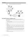
Voice over IP (VoIP) enables a Cisco AS5300 access server to carry voice traffic (for example,
telephone calls and faxes) over an IP network. VoIP is primarily a software feature; however, to use
this feature on the Cisco AS5300, you must install a VoIP feature card (VFC). Each VFC can hold
up to five digital signal processor modules (DSPMs). The VFC utilizes the Cisco AS5300’s quad
T1/E1 Public Switched Telephone Network (PSTN) interface and LAN or WAN routing capabilities
to provide up to a 48/60 channel gateway for VoIP packetized voice traffic. For more information
about the physical characteristics, installing, or configuring a VFC in your Cisco AS5300 access
server, refer to Installing Voice over IP Feature Cards in Cisco AS5300 Universal Access Servers,
which came with your your VFC.
VoIP for the Cisco AS5300 has two primary applications:
•
It provides a central-site telephony termination facility for VoIP traffic from multiple
voice-equipped remote office facilities.
•
It provides a PSTN gateway for Internet telephone traffic. VoIP used as a PSTN gateway
leverages the standardized use of H.323-based Internet telephone client applications.
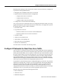
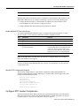
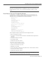
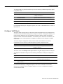
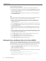
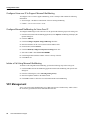
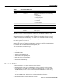
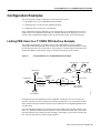
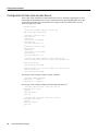
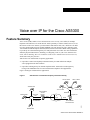
Figure 1 and Figure 2 illustrate these applications.
Figure 1
VoIP Used as a Central-Site Telephony Termination Facility
729 411-5002
729 411-5003
408 555-1001
729 411-5001
10.1.1.1
1:D
T1 ISDN PRI
408 555-3001
Voice port 0:D
IP
cloud
WAN
10.1.1.2
Cisco AS5300
Access Server 2
10351
408 555-2001
Cisco AS5300
Access
Voice port
Server 1
0:D
WAN
729 411-5004
T1
ISDN PRI
Voice over IP for the Cisco AS5300 1
Feature Summary
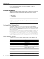
Figure 2
VoIP Used as a PSTN Gateway for Internet Telephone Traffic
408 526-4000
408 526-4001
408 526-4002
PSTN
408 526-4003
310 520-1001
310 520-1002
Central
office
310 520-1000
310 520-1003
Voice port
1/0/0
Cisco AS5300
10.1.1.1
10.1.1.2
Cisco 3640
10352
IP
cloud
How VoIP Processes a Telephone Call
Before configuring VoIP on your Cisco AS5300, it helps to understand what happens at an
application level when you place a call using VoIP. The general flow of a two-party voice call using
VoIP is as follows:
1 The user picks up the handset; this signals an off-hook condition to the signalling application part
of VoIP in the Cisco AS5300.
2 The session application part of VoIP issues a dial tone and waits for the user to dial a telephone
number.
3 The user dials the telephone number; those numbers are accumulated and stored by the session
application.
4 After enough digits are accumulated to match a configured destination pattern, the telephone
number is mapped to an IP host via the dial plan mapper. The IP host has a direct connection to
either the destination telephone number or a PBX that is responsible for completing the call to
the configured destination pattern.
5 The session application then runs the H.323 session protocol to establish a transmission and a
reception channel for each direction over the IP network. If the call is being handled by a PBX,
the PBX forwards the call to the destination telephone. If RSVP has been configured, the RSVP
reservations are put into effect to achieve the desired quality of service (QoS) over the IP
network.
6 The CODECs are enabled for both ends of the connection and the conversation proceeds using
RTP/UDP/IP as the protocol stack.
2
Cisco IOS Release 12.0(3)T
Benefits
7 Any call-progress indications (or other signals that can be carried in-band) are cut through the
voice path as soon as an end-to-end audio channel is established. Signalling that can be detected
by the voice ports (for example, in-band DTMF digits after the call setup is complete) is also
trapped by the session application at either end of the connection and carried over the IP network
encapsulated in RTCP using the RTCP APP extension mechanism.
8 When either end of the call hangs up, the RSVP reservations are torn down (if RSVP is used) and
the session ends. Each end becomes idle, waiting for the next off-hook condition to trigger
another call setup.
Benefits
•
•
•
•
Toll bypass
Remote PBX presence over WANs
Unified voice/data trunking
POTS-Internet telephony gateways
List of Terms
ACOM—Term used in G.165, “General Characteristics of International Telephone Connections and
International Telephone Circuits: Echo Cancellers.” ACOM is the combined loss achieved by the
echo canceller, which is the sum of the echo return loss, echo return loss enhancement, and nonlinear
processing loss for the call.
A-law—A companding technique commonly used in Europe. A-law is standardized as a 64-kbps
CODEC in ITU-T G.711.
Call leg—A logical connection between the router and either a telephony endpoint over a bearer
channel, or another endpoint using a session protocol.
CAS—Channel associated signalling. In E1 applications, timeslot 16 is used to transmit CAS
information. Each frame’s timeslot 16 carries signalling information (ABCD bits) for two of the
B-channel timeslots.
CIR—Committed information rate. The average rate of information transfer a subscriber (for
example, the network administrator) has stipulated for a Frame Relay PVC.
CODEC—coder-decoder. Device that typically uses pulse code modulation to transform analog
signals into a digital bit stream and digital signals back into analog signals. In Voice over IP, it
specifies the voice coder rate of speech for a dial peer.
Data link connection identifier (DLCI)—Frame Relay virtual circuit number corresponding to a
particular destination. The DLCI is part of the Frame Relay header and is usually 10 bits long.
Dial peer—An addressable call endpoint. In Voice over IP, there are two kinds of dial peers: POTS
and VoIP. In Voice over IP, you use dial peers to assign particular characteristics to call legs.
DS0—A 64-kbps channel on an E1 or T1 WAN interface.
DSP—Digital Signal Processor.
DTMF—Dual tone multifrequency. Use of two simultaneous voice-band tones for dial (such as
touch tone).
E1—Wide-area digital transmission scheme. E1 is the European equivalent of a T1 line. The E1’s
higher clock rate (2.048 MHz) allows for 32 64-kbps channels, which include one channel for
framing and one channel for D-channel information.
Voice over IP for the Cisco AS5300 3
Platforms
FIFO—First-in, first-out. In data communication, FIFO refers to a buffering scheme where the first
byte of data entering the buffer is the first byte retrieved by the CPU. In telephony, FIFO refers to a
queueing scheme where the first calls received are the first calls processed.
ISDN—Integrated Services Digital Network. ISDN is a communications protocol, offered by
telephone companies, that permits telephone networks to carry data, voice, and other traffic.
Multilink PPP—Multilink Point-to-Point Protocol. This protocol is a method of splitting,
recombining, and sequencing datagrams across multiple logical data links.
PBX—Private Branch Exchange. Privately owned central switching office.
PLAR—Private Line Auto Ringdown. PLAR is a leased voice circuit that connects two telephones.
When either telephone handset is lifted, the other telephone automatically rings.
POTS—Plain old telephone service. Basic telephone service supplying standard single-line
telephones, telephone lines, and access to the Public Switched Telephone Network.
POTS dial peer—Dial peer connected via a traditional telephony network. POTS peers point to a
particular voice port on a voice network device.
PRI—Primary Rate Interface. PRI is an ISDN interface to primary rate access. Primary rate access
consists of a single 64-kbps D channel plus 23 T1 or 30 E1 B channels for voice or data.
PSTN—Public Switched Telephone Network. PSTN refers to the local telephone company.
PVC—Permanent virtual circuit.
QoS—Quality of service, which refers to the measure of service quality provided to the user.
RSVP—Resource Reservation Protocol. This protocol supports the reservation of resources across
an IP network.
T1—Digital WAN carrier facility. T1 transmits DS1 formatted data at 1.544 Mbps through the
telephone-switching network, using AMI or B8ZS coding. T1 is the North American equivalent of
an E1 line.
Trunk—Service that allows quasi-transparent connections between two PBXs, a PBX and a local
extension, or some ther combination of telephony interfaces to be permanently conferenced together
by the esession application and signalling passed transparently through the IP network.
U-law—A companding technique commonly used in North America. U-law is standardized as a
64-kbps CODEC in ITU-T G.711.
VoIP dial peer—Dial peer connected via a packet network; in the case of Voice over IP, this is an
IP network. VoIP peers point to specific VoIP devices.
Platforms
The Voice over IP feature is supported on the following Cisco device platforms:
•
•
Cisco AS5300 access servers
Cisco 3600 series routers
The configuration procedure described in this document pertains to the Cisco AS5300. For
information on how to configure Voice over IP on Cisco 3600 series routers, refer to the Cisco IOS
Release 12.0 Voice, Video, and Home Applications Configuration Guide.
4
Cisco IOS Release 12.0(3)T
List of Terms
Prerequisites
Before you can configure your Cisco AS5300 to use Voice over IP, you must first do the following:
•
Establish a working IP network. For more information about configuring IP, refer to the
“IP Overview,” “Configuring IP Addressing,” and “Configuring IP Services” chapters in the
Cisco IOS 12.0 Network Protocols Configuration Guide, Part 1.
•
Complete basic configuration for the AS5300, which includes, as a minimum, the following
tasks:
— Configure a host name and password for the AS5300
— Configure the Ethernet 10BaseT/100BaseT interface of your AS5300 so that it can be
recognized as a device on the Ethernet LAN
— Configure the AS5300 interfaces for ISDN PRI lines
— Configure the ISDN D channels for each ISDN PRI line
For more information about any of the these configuration tasks, refer to the Cisco AS5300
Universal Access Server Software Configuration Guide.
•
Install the VFC into the appropriate slot of your Cisco AS5300 access server. Each VFC can hold
up to five digital signal processor modules (DSPMs), enabling processing for up to 30 B
channels. For more information about the physical characteristics of the VFCs or DSPMs, or how
to install them, refer to Installing Voice over IP Feature Cards in Cisco AS5300 Universal Access
Servers, which came with your VFC.
•
•
•
Complete your company’s dial plan.
Establish a working telephony network based on your company’s dial plan.
Integrate your dial plan and telephony network into your existing IP network topology. Merging
your IP and telephony networks depends on your particular IP and telephony network topology.
In general, Cisco recommends the following suggestions:
— Use canonical numbers wherever possible. It is important to avoid situations where
numbering systems are significantly different on different routers or access servers in your
network.
— Make routing and dialing transparent to the user—for example, avoid secondary dial tones
from secondary switches, where possible.
— Contact your PBX vendor for instructions about how to reconfigure the appropriate PBX
interfaces.
Supported MIBs and RFCs
This feature supports the following MIBs:
•
•
•
CISCO-ANALOG-VOICE-IF-MIB
CISCO-VOICE-DIAL-CONTROL-MIB
CISCO-VOICE-IF-MIB
For descriptions of supported MIBs and how to use MIBs, see Cisco’s MIB Web site on CCO at
http://www.cisco.com/public/sw-center/netmgmt/cmtk/mibs.shtml.
Voice over IP for the Cisco AS5300 5
Configuration Tasks
This feature supports the following RFCs:
•
RFC 1889—RTP: A Transport Protocol for Real-Time Applications, January 1996; H.
Schulzrinne, GMD Fokus; S. Casner, Precept Software, Inc; R. Frederick, Xerox Palo Alto
Research Centre; V. Jacobson, Lawrence Berkeley National Laboratory
•
RFC 1890—RTP Profile for Audio and Video Conferences with Minimal Control, January 1996;
H. Schulzrinne, GMD Fokus
•
RFC 2127—ISDN Management Information Base using SMIv2, March 1997; G. Roeck, Editor;
Cisco Systems
•
RFC 2128—Dial Control Management Information Base using SMIv2, March 1997; G. Roeck,
Editor; Cisco Systems
•
•
ITU-T H.323—Packet-Based Multimedia Communications Systems, February 1998
ITU-T Q.400-490 series—Signalling System R2, 1988 to 1993
Configuration Tasks
After you have analyzed your dial plan and decided how to integrate it into your existing IP network,
you are ready to configure your network devices to support Voice over IP. The actual configuration
procedure depends entirely on the topology of your voice network, but in general you need to
perform the following tasks:
•
Configure IP Networks for Real-Time Voice Traffic
— Configure Multilink PPP with Interleaving
— Configure RTP Header Compression
— Configure Custom Queueing
— Configure Weighted Fair Queueing
•
•
Configure Frame Relay for Voice Over IP (if needed for your network topology)
Configure Voice Ports
— Configure ISDN PRI Voice Ports
— Configure E1 R2 Voice Ports
— Configure T1 CAS Voice Ports
•
Configure Number Expansion
— Create a Number Expansion Table
— Configure Number Expansion
•
Configure Dial Peers
— Create a Peer Configuration Table
— Configure POTS Peers
— Configure VoIP Peers
6
Cisco IOS Release 12.0(3)T
Configure IP Networks for Real-Time Voice Traffic
Depending on the topology of your network or the resources used in your network, you might need
to perform the following additional tasks:
•
•
Distinguish Voice and Modem Calls on the Cisco AS5300
Optimize Dial Peer and Network Interface Configurations
— Configure IP Precedence for Dial Peers
— Configure RSVP for Dial Peers
— Configure CODEC and VAD for Dial Peers
•
Configure Voice over IP for Microsoft NetMeeting
Voice over IP for the Cisco AS5300 also offers VFC management features that enable you to easily
upgrade and manage the system software stored in VFC Flash memory. You might need to perform
the following tasks to manage VCWare or DSPWare:
•
•
Download VCWare
Copy Flash Files to the VFC
— Download VCWare to the VFC from the AS5300 Motherboard
— Download VCWare to the VFC from a TFTP Server
•
•
•
•
•
Unbundle VCWare
Add Files to the Default File List
Add CODECs to the Capability List
Delete Files from VFC Flash Memory
Erase the VFC Flash Memory
All of these tasks are described in the following sections.
Configure IP Networks for Real-Time Voice Traffic
You need to have a well-engineered network end-to-end when running delay-sensitive applications
such as VoIP. Fine-tuning your network to adequately support VoIP involves a series of protocols and
features geared toward quality of service (QoS). It is beyond the scope of this document to explain
the specific details relating to wide-scale QoS deployment. Cisco IOS software provides many tools
for enabling QoS on your backbone, such as Random Early Detection (RED), Weighted Random
Early Detection (WRED), fancy queueing (meaning custom, priority, or weighted fair queueing),
and IP Precedence. To configure your IP network for real-time voice traffic, you need to consider the
entire scope of your network, then select the appropriate QoS tool or tools.
It is important to remember that QoS must be configured throughout your network—not just on the
AS5300 devices running VoIP—to improve voice network performance. Not all QoS techniques are
appropriate for all network routers. Edge routers and backbone routers in your network do not
necessarily perform the same operations; the QoS tasks they perform might differ as well. To
configure your IP network for real-time voice traffic, you need to consider the functions of both edge
and backbone routers in your network, then select the appropriate QoS tool or tools.
In general, edge routers perform the following QoS functions:
•
•
•
Packet classification
Admission control
Bandwidth management
Voice over IP for the Cisco AS5300 7
Configuration Tasks
•
Queueing
In general, backbone routers perform the following QoS functions:
•
•
•
High-speed switching and transport
Congestion management
Queue management
Scalable QoS solutions require cooperative edge and backbone functions.
Note In a subsequent Cisco IOS release, we have implemented enhancements to improve QoS on
low speed, wide-area links, such as ISDN, MLPPP, and Frame Relay running on edge routers. For
more information about these enhancements, refer to the Cisco IOS Release 12.0(5)T “IP RTP”
feature module.
Although they are not mandatory, some QoS tools have been identified as being valuable in
fine-tuning your network to support real-time voice traffic. To configure your IP network for QoS
using these tools, perform one or more of the following tasks:
•
•
•
•
Configure Multilink PPP with Interleaving
Configure RTP Header Compression
Configure Custom Queueing
Configure Weighted Fair Queueing
Each of these components is discussed in the following sections.
Configure Multilink PPP with Interleaving
Multiclass Multilink PPP interleaving allows large packets to be multilink-encapsulated and
fragmented into smaller packets to satisfy the delay requirements of real-time voice traffic; small
real-time packets, which are not multilink-encapsulated, are transmitted between fragments of the
large packets. The interleaving feature also provides a special transmit queue for the smaller,
delay-sensitive packets, enabling them to be transmitted earlier than other flows. Interleaving
provides the delay bounds for delay-sensitive voice packets on a slow link that is used for other
best-effort traffic.
Note Interleaving applies only to interfaces that can configure a multilink bundle interface. These
interfaces include virtual templates, dialer interfaces, and Integrated Services Digital Network
(ISDN) Basic Rate Interface (BRI) or Primary Rate Interface (PRI) interfaces.
In general, Multilink PPP with interleaving is used in conjunction with weighted fair queueing and
RSVP or IP Precedence to ensure voice packet delivery. Use Multilink PPP with interleaving and
weighted fair queueing to define how data will be managed; use RSVP or IP Precedence to give
priority to voice packets.
You should configure Multilink PPP if the following conditions exist in your network:
•
•
8
Point-to-point connection using PPP encapsulation
Slow links
Cisco IOS Release 12.0(3)T
Configure RTP Header Compression
Note Multilink PPP should not be used on links greater than 2 Mbps.
Multilink PPP support for interleaving can be configured on virtual templates, dialer interfaces, and
ISDN BRI or PRI interfaces. To configure interleaving, you need to perform the following tasks:
•
Configure the dialer interface or virtual template, as defined in the relevant chapters of the
Cisco IOS Release 12.0 Dial Solutions Configuration Guide.
•
Configure Multilink PPP and interleaving on the interface or template.
Enable Multilink PPP and Interleaving
To configure Multilink PPP and interleaving on a configured and operational interface or virtual
interface template, use the following commands in interface configuration mode:
Step
Command
Purpose
1
ppp multilink
Enables Multilink PPP.
2
ppp multilink interleave
Enables real-time packet interleaving.
3
ppp multilink fragment-delay milliseconds
Optionally, configures a maximum fragment delay.
4
ip rtp reserve lowest-UDP-port range-of-ports
[maximum-bandwidth]
Reserves a special queue for real-time packet flows
to specified destination User Datagram Protocol
(UDP) ports, allowing real-time traffic to have
higher priority than other flows. This command
applies only if you have not configured RSVP.
Note The ip rtp reserve command can be used instead of configuring RSVP. If you configure
RSVP, this command is not required.
For more information about Multilink PPP, refer to the the Cisco IOS Release 12.0 Dial Solutions
Configuration Guide.
Multilink PPP Configuration Example
The following example defines a virtual interface template that enables Multilink PPP with
interleaving and a maximum real-time traffic delay of 20 milliseconds, and then applies that virtual
template to the Multilink PPP bundle:
interface virtual-template 1
ppp multilink
encapsulated ppp
ppp multilink interleave
ppp multilink fragment-delay 20
ip rtp reserve 16384 100 64
multilink virtual-template 1
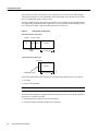
Configure RTP Header Compression
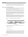
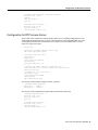
Real-Time Transport Protocol (RTP) is used for carrying packetized audio traffic over an IP network.
RTP header compression compresses the IP/UDP/RTP header in an RTP data packet from 40 bytes
to approximately 2 to 4 bytes (most of the time), as shown in Figure 3.
Voice over IP for the Cisco AS5300 9
Configuration Tasks
This compression feature is beneficial if you are running Voice over IP over slow links. Enabling
compression on both ends of a low-bandwidth serial link can greatly reduce the network overhead if
there is substantial RTP traffic on that slow link.
Typically, an RTP packet has a payload of approximately 20 to 160 bytes for audio applications that
use compressed payloads. RTP header compression is especially beneficial when the RTP payload
size is small (for example, compressed audio payloads of 20 to 50 bytes).
Figure 3
RTP Header Compression
Before RTP header compression:
20 bytes
IP
8 bytes 12 bytes
UDP
RTP
Header
Payload
20 to 160 bytes
After RTP header compression:
2 to 4 bytes
IP/UDP/RTP header
20 to 160 bytes
12076
Payload
You should configure RTP header compression if the following conditions exist in your network:
•
•
Slow links
Need to save bandwidth
Note RTP header compression should not be used on links greater than 2 Mbps.
Perform the following tasks to configure RTP header compression for Voice over IP. The first task is
required; the second task is optional.
•
•
10
Enable RTP Header Compression on a Serial Interface
Change the Number of Header Compression Connections
Cisco IOS Release 12.0(3)T
Configure Custom Queueing
Enable RTP Header Compression on a Serial Interface
To use RTP header compression, you need to enable compression on both ends of a serial
connection. To enable RTP header compression, use the following command in interface
configuration mode:
Command
Purpose
ip rtp header-compression [passive]
Enables RTP header compression.
If you include the passive keyword, the software compresses outgoing RTP packets only if incoming
RTP packets on the same interface are compressed. If you use the command without the passive
keyword, the software compresses all RTP traffic.
Change the Number of Header Compression Connections
By default, the software supports a total of 16 RTP header compression connections on an interface.
To specify a different number of RTP header compression connections, use the following command
in interface configuration mode:
Command
Purpose
ip rtp compression connections number
Specifies the total number of RTP header
compression connections supported on an interface.
RTP Header Compression Configuration Example
The following example enables RTP header compression for a serial interface:
interface 0:23
ip rtp header-compression
encapsulation ppp
ip rtp compression-connections 25
For more information about RTP header compression, see the Cisco IOS Release 12.0 Network
Protocols Configuration Guide, Part 1.
Configure Custom Queueing
Some QoS features, such as IP RTP reserve and custom queueing, are based on the transport protocol
and the associated port number. Real-time voice traffic is carried on UDP ports in the range 16384
to 16624. This number is derived from the following formula:
16384 = 4(number of voice ports in the AS5300)
Custom queueing and other methods for identifying high priority streams should be configured for
these port ranges. For more information about custom queueing, refer to the the Cisco IOS Release
12.0 Quality of Service Solutions Configuration Guide.
Configure Weighted Fair Queueing
Weighted fair queueing ensures that queues do not starve for bandwidth and that traffic gets
predictable service. Low-volume traffic streams receive preferential service; high-volume traffic
streams share the remaining capacity, obtaining equal or proportional bandwidth.
Voice over IP for the Cisco AS5300 11
Configuration Tasks
In general, weighted fair queueing is used in conjunction with Multilink PPP with interleaving and
RSVP or IP Precedence to ensure that voice packet delivery. Use weighted fair queueing with
Multilink PPP to define how data will be managed; use RSVP or IP Precedence to give priority to
voice packets. For more information about weighted fair queueing, refer to the Cisco IOS Release
12.0 Quality of Service Solutions Configuration Guide.
Configure Frame Relay for Voice Over IP
You need to consider certain factors when configuring Voice over IP for it to run smoothly over
Frame Relay. A public Frame Relay cloud provides no guarantees for QoS. For real-time traffic to
be transmitted in a timely manner, the data rate must not exceed the CIR or there is the possibility
that packets will be dropped. In addition, Frame Relay traffic shaping and RSVP are mutually
exclusive, which is particularly important to remember if multiple DLCIs are carried on a single
interface.
For Frame Relay links with slow output rates (less than or equal to 64 kbps), where data and voice
are being transmitted over the same PVC, Cisco recommends the following solutions:
•
Separate DLCIs for voice and data—By providing a separate subinterface for voice and data, you
can use the appropriate QoS tool per line. For example, each DLCI would use 32 kbps of a
64-kbps line.
— Apply adaptive traffic shaping to both DLCIs.
— Use RSVP or IP Precedence to prioritize voice traffic.
— Use compressed RTP to minimize voice packet size.
— Use weighted fair queueing to manage voice traffic.
•
Lower MTU size—Voice packets are generally small. If you lower the MTU size (for example,
to 300 bytes), large data packets can be broken up into smaller data packets that can more easily
be interwoven with voice packets.
Note Some applications do not support a smaller MTU size. If you decide to lower MTU size,
use the ip mtu command; this command affects only IP traffic.
Note Lowering the MTU size affects data throughput speed.
•
CIR equal to line rate—Make sure that the data rate does not exceed the CIR by using generic
traffic shaping.
— Use compressed RTP to minimize voice packet header size.
•
Traffic shaping—Use adaptive traffic shaping to throttle back the output rate based on the
backward explicit congestion notification (BECN) bit. If the feedback from the switch is ignored,
packets (both data and voice) might be discarded. Because the Frame Relay switch does not
distinguish between voice and data packets, voice packets could be discarded, which would result
in a deterioration of voice quality.
— Use compressed RTP, reduced MTU size, and adaptive traffic shaping based on BECN to
hold data rate to CIR.
— Use generic traffic shaping to obtain a low interpacket wait time. For example, set the Bc
parameter to 4000 to obtain an interpacket wait of 125 milliseconds.
12
Cisco IOS Release 12.0(3)T
Frame Relay for Voice over IP Configuration Example
Note We recommend FRF.12 fragmentation setup rules for Voice over IP connections over Frame
Relay. FRF.12 was implemented in the Cisco IOS Release 12.0(4)T. For more information, refer to
the Cisco IOS Release 12.0(4)T “Voice over Frame Relay using FRF.11 and FRF.12” feature
module.
Frame Relay for Voice over IP Configuration Example
For Frame Relay, it is customary to configure a main interface and several subinterfaces, one
subinterface per PVC. The following example configures a Frame Relay main interface and a
subinterface so that voice and data traffic can be successfully transported:
interface Serial0/0
ip mtu 300
no ip address
encapsulation frame-relay
no ip route-cache
no ip mroute-cache
fair-queue 64 256 1000
frame-relay ip rtp header-compression
interface Serial0/0.1 point-to-point
ip mtu 300
ip address 40.0.0.7 255.0.0.0
ip rsvp bandwidth 48 48
no ip route-cache
no ip mroute-cache
bandwidth 64
traffic-shape rate 32000 4000 4000
frame-relay interface-dlci 16
frame-relay ip rtp header-compression
In this configuration example, the main interface has been configured as follows:
•
•
MTU size of IP packets is 300 bytes.
•
•
•
Encapsulation method is Frame Relay.
No IP address is associated with this serial interface. The IP address must be assigned for the
subinterface.
Fair queueing is enabled.
IP RTP header compression is enabled.
The subinterface has been configured as follows:
•
•
•
•
•
•
MTU size is inherited from the main interface.
IP address for the subinterface is specified.
Bandwidth is set to 64 kbps.
Generic traffic shaping is enabled with 32-kbps CIR where Bc = 4000 bits and Be = 4000 bits.
Frame Relay DLCI number is specified.
IP RTP header compression is enabled.
Note When traffic bursts over the CIR, output rate is held at the speed configured for the CIR (for
example, traffic will not go beyond 32 kbps if CIR is set to 32 kbps).
Voice over IP for the Cisco AS5300 13
Configuration Tasks
For more information about Frame Relay, refer to the Cisco IOS Release 12.0 Wide-Area
Networking Configuration Guide.
Configure Voice Ports
When an interface on the Cisco AS5300 is carrying voice data, it is referred to as a voice port. Voice
over IP on the Cisco AS5300 is supported over three different interface types in this release:
•
•
•
ISDN PRI
E1R2 Signalling
T1-CAS Signalling
Note A voice port was created automatically when you installed the VFC in the Cisco AS5300 and
configured an ISDN PRI group. Configuring an ISDN PRI group is part of the basic Cisco AS5300
configuration procedure. For more information, refer to the Cisco AS5300 Universal Access Server
Software Configuration Guide.
Configure ISDN PRI Voice Ports
With ISDN PRI, signalling in Voice over IP for the AS5300 is handled by ISDN PRI group
configuration. After ISDN PRI has been configured for both B and D channels for both ISDN PRI
lines, you need to issue the isdn incoming-voice command on the serial interface (acting as the D
channel) to ensure a dial tone.
Under most circumstances, the default voice-port command values are adequate to configure voice
ports to transport voice data over your existing IP network. Because of the inherent complexities
involved with PBX networks, you might need specific voice-port values configured, depending on
the specifications of the devices in your telephony network. For more information regarding specific
voice-port configuration commands, refer to the “Command Reference” section of this document.
Configure ISDN PRI for Voice over IP
To configure a voice port, use the following commands beginning in global configuration mode:
14
Step
Command
Purpose
1
isdn switch-type switch-type
Defines the telephone company’s switch type.
2
controller T1 0
Enables the T1 0 controller and enters controller
configuration mode.
3
framing esf
Defines the framing characteristics.
4
clock source line primary
Configures one T1 line to serve as the primary
clock source.
5
linecode value
Sets the line code type to match that of your
telephone company service provider.
6
pri-group timeslots range
Configures ISDN PRI.
7
controller T1 1
Enables the T1 1 controller and enters controller
configuration mode.
8
framing esf
Defines the framing characteristics.
9
linecode value
Sets the line code type to match that of your
telephone company service provider.
Cisco IOS Release 12.0(3)T
Configure E1 R2 Voice Ports
Step
Command
Purpose
10
pri-group timeslots range
Configures ISDN PRI.
11
interface Serial0:23
Configures the IDSN D channel for the first ISDN
PRI line. (The serial interface is the D channel.)
12
ip address ip-address
Specifies an IP address for the interface.
13
isdn incoming-voice {voice | modem}
Enables incoming ISDN voice calls.
14
interface Serial1:23
Configures the IDSN D channel for the second
ISDN PRI line.
15
ip address ip-address
Specifies an IP address for the interface.
16
isdn incoming-voice {voice | modem}
Enables incoming ISDN voice calls.
Verify ISDN PRI Configuration
You can check the validity of your voice port configuration by performing the following tasks:
•
•
Use the show voice port command to verify that the data configured is correct.
•
Enter a DTMF digit. If the dial tone stops, you have two-way voice connectivity with the router.
If you have not configured your device to support direct inward dial (DID), dial in to the router
and see if you have dial tone.
Tips
If you are having trouble connecting a call and you suspect the problem is associated with voice-port
configuration, you can try to resolve the problem by performing the following tasks:
•
Ping the associated IP address to confirm connectivity. If you cannot successfully ping your
destination, refer to the “Configuring IP” chapter in the Cisco IOS 12.0 Network Protocols
Configuration Guide, Part 1.
•
Determine if the VFC has been correctly installed. For more information, refer to Installing
Voice-over-IP Feature Cards in Cisco AS5300 Universal Access Servers, which came with your
voice network module (VNM).
•
•
Use the show vfc slot number command to learn if the VFC is operational.
•
With T1 lines, determine if your a-law setting is correct. With E1 lines, determine if your u-law
setting is correct. Use the cptone command to configure both a-law or u-law values. For more
information about the cptone command, refer to the “Command Reference” section of this
document.
•
If dialing cannot occur, use the debug isdn q931 command to check the ISDN configuration.
Use the show isdn status command to view layer status information. If you receive a status
message stating that Layer 1 is deactivated, make sure the cable connection is not loose or
disconnected. (This status message indicates a problem at the physical layer.)
Configure E1 R2 Voice Ports
The Voice over IP VNM for the Cisco AS5300 supports E1 R2 signalling as well as ISDN PRI. R2
signalling is an international signalling standard that is common to channelized E1 networks.
However, there is no single signalling standard for R2. The ITU-T Q.400-Q.490 recommendation
Voice over IP for the Cisco AS5300 15
Configuration Tasks
defines R2, but a number of countries and geographic regions implement R2 in entirely different
ways. Cisco Systems addresses this lack of standards by supporting many localized implementations
of R2 signalling in its Cisco IOS software.
Cisco Systems’ E1 R2 signalling default is ITU, which supports the technology used in the following
countries: Denmark, Finland, Germany, Russia (ITU variant), Hong Kong (ITU variant), and South
Africa (ITU variant). The expression “ITU variant” means there are multiple R2 signalling types in
the specified country, but Cisco supports the ITU variant.
Cisco Systems also supports specific local variants of E1 R2 signalling in the following regions,
countries, and corporations:
•
•
•
•
•
•
•
•
•
•
•
•
•
•
•
•
•
•
•
•
•
•
•
•
•
•
•
•
•
16
Argentina
Australia
Brazil
China
Colombia
Costa Rica
East Europe (includes Croatia, Russia, and the Slovak Republic)
Ecuador ITU
Ecuador LME
Greece
Guatemala
Hong Kong (China variant)
Indonesia
Israel
Korea
Malaysia
Mexico (Telmex corporation)
Mexico (Telnor corporation)
New Zealand
Paraguay
Peru
Philippines
Saudi Arabia
Singapore
South Africa (Panaftel variant )
Thailand
Uruguay
Venezuela
Vietnam
Cisco IOS Release 12.0(3)T
Configure E1 R2 Voice Ports
Of the local variants listed above, the following local variants have been verified:
•
•
•
•
•
•
Argentina
Brazil
China
Mexico (Telmax)
Singapore
Thailand
R2 signalling is channelized E1 signalling used in Europe, Asia, and South America. It is equivalent
to channelized T1 signalling in North America. There are two types of R2 signalling: line signalling
and interregister signalling. R2 line signalling includes R2 digital, R2 analog, and R2 pulse. R2
interregister signalling includes R2 compelled, R2 noncompelled, and R2 semicompelled. These
signalling types are configured using the cas-group command.
Many countries and regions have their own E1 R2 variant specifications, which supplement the
ITU-T Q.400-Q.490 recommendation for R2 signalling. Unique E1 R2 signalling parameters for
specific countries and regions are set by entering the cas-custom channel command followed by the
country name command.
Cisco’s implementation of R2 signalling has dialed number identification service (DNIS) support
turned on by default. If you enable the automatic number identification (ani) option, the collection
of DNIS information is still performed. Specifying the ani option does not disable DNIS collection.
DNIS is the number being called. ANI is the caller’s number. For example, if you are configuring
router A to call router B, then the DNIS number is assigned to router B; the ANI number is assigned
to router A. ANI is similar to Caller ID.
Configure E1 R2 Signalling for Voice over IP
To configure E1 R2 signalling, use the following commands beginning in global configuration mode:
Step
Command
Purpose
1
controller e1 number
Specifies the E1 controller that you want to
configure with R2 signalling.
2
cas-group channel timeslots range type {r2-analog |
r2-digital | r2-pulse} [dtmf | r2-compelled [ani] |
r2-non-compelled [ani] | r2-semi-compelled [ani]]
Configures R2 channel-associated
signalling on the E1 controller. For a
complete description of the available R2
options, refer to the cas-group (controller
e1) command in the Cisco IOS Release
12.0 Dial Solutions Command Reference.
3
cas-custom channel
Enters cas-custom mode. In this mode, you
can localize E1 R2 signalling parameters,
such as specific R2 country settings for
Hong Kong.
For the customization to take effect, the
channel number used in the cas-custom
command must match the channel number
specified by the cas-group command.
Voice over IP for the Cisco AS5300 17
Configuration Tasks
Step
Command
Purpose
4
country name use-defaults
Specifies the local country, region, or
corporation specification to use with R2
signalling. Replace the name variable with
one of the supported country names.
Cisco strongly recommends that you
include the use-defaults option, which
engages the default settings for a specific
country. The default setting for all
countries is ITU.
See the cas-custom command in the Cisco
IOS Release 12.0 Dial Solutions Command
Reference for the list of supported regions,
countries, or corporation specifications.
5
• ani-digits
• answer-signal
• caller-digits
• category
• default
• dnis-digits
• invert-abcd
• ka
• kd
• metering
• nc-congestion
(Optional) Further customizes the R2
signalling parameters. Some switch types
require you to fine tune your R2 settings.
Do not tamper with these commands unless
you fully understand your switch’s
requirements.
For nearly all network scenarios, the
country name use-defaults command
fully configures your country’s local
settings. You should not need to perform
Step 5.
See the cas-custom command in the Cisco
IOS Release 12.0 Dial Solutions Command
Reference for more information about each
signalling command.
• unused-abcd
• request-category
6
exit
Exits interface configuration mode.
7
voice-port controller-number:channel-number
Enters voice-port configuration mode for
the specified voice port.
8
cptone country-code
Defines the country-specific PCM
encoding and tones. The PCM encoding
type must match the country code defined
by the cas-custom command.
9
exit
Exits voice-port configuration mode.
10
exit
Exits global configuration mode.
As mentioned in the previous configuration steps, the E1 R2 signalling type (whether ITU, ITU
variant, or local variant as defined by the cas-custom command) needs to match the appropriate
PCM encoding type as defined by the cptone command. For countries for which a cptone value has
not yet been defined, you can try the following:
•
•
If the country uses a-law E1 R2 signalling, use the GB value for the cptone command.
If the country uses u-law E1 R2 signalling, use the US value for the cptone command.
For more information about configuring R2 signalling, refer to the Cisco IOS Release 12.0
Dial Solutions Configuration Guide.
18
Cisco IOS Release 12.0(3)T
Configure E1 R2 Voice Ports
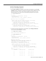
Verify E1 R2 Signalling Configuration
To verify the E1 R2 signalling configuration:
•
Type the show controller e1 command to view the status for all controllers, or type the show
controller e1 number command to view the status for a particular controller. Make sure the status
indicates the controller is up (line 2 in the following example) and no alarms (line 4 in the
following example) or errors (lines 9 and 10 in the following example) have been reported.
5300# show controller e1 0
E1 0 is up.
Applique type is Channelized E1 - balanced
No alarms detected.
Version info of Slot 0: HW: 2, Firmware: 4, PLD Rev: 2
Manufacture Cookie is not programmed.
Framing is CRC4, Line Code is HDB3, Clock Source is Line Primary.
Data in current interval (785 seconds elapsed):
0 Line Code Violations, 0 Path Code Violations
0 Slip Secs, 0 Fr Loss Secs, 0 Line Err Secs, 0 Degraded Mins
0 Errored Secs, 0 Bursty Err Secs, 0 Severely Err Secs, 0 Unavail Secs
Total Data (last 13 15 minute intervals):
0 Line Code Violations, 0 Path Code Violations,
0 Slip Secs, 12 Fr Loss Secs, 0 Line Err Secs, 0 Degraded Mins,
0 Errored Secs, 0 Bursty Err Secs, 0 Severely Err Secs, 12 Unavail Secs
•
To check the robbed-bit signalling status of each channel, type the debug serial interface
command and the show controller e1 command.
as5300#debug serial interface
Serial network interface debugging is on
as5300#show controller e1 0
E1 0 is up.
Applique type is Channelized E1 - balanced
No alarms detected.
Version info of Slot 0: HW:2, Firmware:4, PLD Rev:0
Manufacture Cookie Info:
EEPROM Type 0x0001, EEPROM Version 0x01, Board ID 0x43,
Board Hardware Version 1.0, Item Number 73-2218-4,
Board Revision A0, Serial Number 07805788,
PLD/ISP Version 0.0, Manufacture Date 19-Feb-1998.
Framing is NO-CRC4, Line Code is HDB3, Clock Source is Line Primary.
Data in current interval (135 seconds elapsed):
0 Line Code Violations, 0 Path Code Violations
0 Slip Secs, 0 Fr Loss Secs, 0 Line Err Secs, 0 Degraded Mins
0 Errored Secs, 0 Bursty Err Secs, 0 Severely Err Secs, 0 Unavail
Secs
Robbed bit signals state:
timeslots
rxA rxB rxC rxD
txA txB txC txD
1
2
3
4
5
6
7
0
0
0
1
1
0
1
0
0
0
0
0
0
0
0
0
0
0
0
0
0
1
1
1
1
1
1
1
0
0
0
1
1
0
1
1
1
1
0
0
1
0
0
0
0
0
0
0
0
1
1
1
1
1
1
1
Voice over IP for the Cisco AS5300 19
Configuration Tasks
8
9
10
11
12
13
14
15
17
18
19
20
21
22
23
24
25
26
27
28
29
30
31
1
1
1
0
0
1
1
1
0
1
1
0
1
1
1
0
0
0
0
0
0
0
0
0
0
0
0
0
0
0
0
0
0
0
0
0
0
0
0
0
0
0
0
1
1
0
0
0
0
0
0
0
0
0
0
0
0
0
0
0
0
0
0
0
0
0
1
0
0
1
1
1
1
0
1
1
1
1
1
1
1
1
1
1
1
1
1
1
0
0
1
0
1
1
1
0
0
1
1
1
0
1
1
0
1
1
1
0
0
0
0
0
0
0
1
0
0
0
1
0
0
0
0
1
0
0
1
0
0
0
1
1
1
1
0
1
0
0
0
0
0
0
0
0
0
0
0
0
0
0
0
0
0
0
0
0
0
0
0
0
0
1
1
1
1
0
1
1
1
1
1
1
1
1
1
1
1
1
1
1
0
1
1
0
Tips
If the connection does not come up, check for the following:
•
•
•
•
•
•
Loose wires, splices, connectors, shorts, bridge taps, and grounds
Backward transmit and receive
Mismatched framing types (for example, CRC-4 versus no-CRC-4)
Transmit and receive pair separation (crosstalk)
Faulty line cards or repeaters
Noisy lines (for example, power and crosstalk)
If you see errors on the line or the line is going up and down, check for the following:
20
•
Mismatched line codes—for example, high density bipolar 3 (HDB3) versus alternate mark
inversion (AMI)
•
•
Receive level
Frame slips due to poor clocking plan
Cisco IOS Release 12.0(3)T
Configure T1 CAS Voice Ports
Configure T1 CAS Voice Ports
CAS is the transmission of signalling information within the voice channel. Various types of CAS
signalling are available in the T1 world. The most common forms of CAS signalling are loop-start,
ground-start, and E&M. The main disadvantage of CAS signalling is its use of user bandwidth to
perform signalling functions. CAS signalling is often referred to as robbed-bit signalling because
user bandwidth is being “robbed” by the network for other purposes. In addition to receiving and
placing calls, CAS signalling processes the receipt of DNIS and ANI information, which is used to
support authentication and other functions.
T1 CAS capabilities have been implemented on the Cisco AS5300 VFC to enhance and integrate T1
CAS capabilities on common central office (CO) and PBX configurations for voice calls. The
service provider application for T1 CAS includes connectivity to the public network using T1 CAS
from the Cisco AS5300 to the end office switch. In this configuration, the Cisco AS5300 captures
the dialed-number or called-party number information and passes it along to the upper level
applications for interactive voice response (IVR) script selection, modem pooling, and other
applications. Service providers also require access to calling party number, ANI, for user
identification, for billing account number, and in the future, for more complicated call routing.
Service providers who implement VoIP include traditional voice carriers, new voice and data
carriers, and existing Internet service providers. Some of these service providers might use
subscriber side lines for their VoIP connectivity to the PSTN; others might use tandem-type service
provider connections.
T1 CAS Signalling Systems
Voice over IP for the AS5300 supports the following T1 CAS signalling systems:
•
E&M—E&M signalling is typically used for trunks. It is normally the only way that a CO switch
can provide two-way dialing with direct inward dialing. In all the E&M protocols, off-hook is
indicated by A = B = 1, and on-hook is indicated by A = B = 0. If dial pulse dialing is used, the
A and B bits are pulsed to indicate the addressing digits. There are several further important
subclasses of E&M robbed-bit signalling:
— E&M Wink Start—Feature Group B
In the original Wink Start protocol, the terminating side responds to an off-hook from the
originating side with a short wink (transition from on-hook to off-hook and back again). This
wink tells the originating side that the terminating side is ready to receive addressing digits.
After receiving addressing digits, the terminating side then goes off-hook for the duration of
the call. The originating endpoint maintains off-hook for the duration of the call.
— E&M Wink Start—Feature Group D
In Feature Group D Wink Start with Wink Acknowledge protocol, the terminating side
responds to an off-hook from the originating side with a short wink (transition from on-hook
to off-hook and back again) just as in the original Wink Start. This wink tells the originating
side that the terminating side is ready to receive addressing digits. After receiving addressing
digits, the terminating side then provides another wink (called an Acknowledgment Wink)
that tells the originating side that the terminating side has received the dialed digits. The
terminating side then goes off-hook to indicate connection when the ultimate called endpoint
has answered. The originating endpoint maintains off-hook for the duration of the call.
Voice over IP for the Cisco AS5300 21
Configuration Tasks
— E&M Immediate Start
In the Immediate Start protocol, the originating side does not wait for a wink before sending
addressing information. After receiving addressing digits, the terminating side then goes
off-hook for the duration of the call. The originating endpoint maintains off-hook for the
duration of the call.
•
Ground Start / FXS—Ground Start signalling was developed to aid in resolving glare when two
sides of a connection tried to go off-hook at the same time. Two sides of the connection
simultaneously going off-hook creates a problem with loop start signalling because the only way
an incoming call from the network was recognized by the customer premise equipment (CPE)
using loop start was to ring the phone. The 6-second ring cycle left a substantial amount of time
for glare to occur. Ground Start signalling eliminates this problem by providing an immediate
seizure indication from the network to the CPE. This indication tells the CPE that a particular
channel has an incoming call on it. Ground Start is different than E&M in that the A and B bits
do not track each other (that is, A is not necessarily equal to B). When the CO delivers a call, it
“seizes” a channel (goes off-hook) by setting the A bit to 0. The CO equipment also simulates
ringing by toggling the B bit. The terminating equipment goes off-hook when it is ready to
answer the call. Digits are usually not delivered for incoming calls.
Channelized T1 Robbed-Bit Features
Internet service providers can provide switched 56-kbps access to their customers using the
Cisco AS5300. The subset of T1 CAS (robbed bit) supported features are as follows:
Supervisory: Line Side
•
•
•
•
•
fxs-loop-start
fxs-ground-start
sas-loop-start
sas-ground-start
Modified R1
Supervisory: Trunk Side
•
•
•
e&m-fgb
e&m-fgd
e&m-immediate-start
Informational: Line Side
•
DTMF
Informational: Trunk Side
•
•
22
DTMF
MF
Cisco IOS Release 12.0(3)T
Configure T1 CAS Voice Ports
Configure T1 CAS for Voice over IP
To configure T1 CAS for Voice over IP on the Cisco AS5300, use the following commands
beginning in privileged EXEC mode:
Step
Command
Purpose
1
configure terminal
Enters global configuration mode.
2
controller t1 number
Enters controller configuration mode to
configure your controller port. The controller ports are labeled 0 through 3 on
the Quad T1/PRI and E1/PRI cards.
3
framing {sf | esf}
Enters the framing type designated by
your telephone company.
4
clock source line primary
Configures the primary PRI clock
source. Configure other lines as secondary or internal clock sources. Note that
only one PRI can be clock source primary and one PRI can be clock source
secondary.
5
linecode {ami | b8zs | hdb3}
Enters the line code type designated by
your telephone company.
6
cas-group channel timeslots range type signal
Configures all channels for E&M, FXS,
and SAS analog signalling. Enter 1-24
for T1. If E1, type 1-31.
Signalling types include e&m-fgb,
e&m-fgd, e&m-immediate-start,
fxs-ground-start, fxs-loop-start,
sas-ground-start, and sas-loop-start.
You must use the same type of signalling
that your central office uses.
For E1 using the Anadigicom converter,
use cas e&m-fgb signalling.
7
controller t1 number
Enters controller configuration mode to
configure the second controller port
(There are a total of four controller
ports). The controller ports are labeled 0
through 3 on the Quad T1/PRI and
E1/PRI cards.
8
framing {sf | esf}
Enters the framing type designated by
your telephone company.
9
clock source line secondary
Configures the secondary PRI clock
source. Note that only one PRI can be
clock source primary and one PRI can be
clock source secondary.
10
linecode {ami | b8zs | hdb3}
Enters the line code type designated by
your telephone company.
Voice over IP for the Cisco AS5300 23
Configuration Tasks
Step
Command
Purpose
11
cas-group channel timeslots range type signal
Configures all channels for E&M, FXS,
and SAS analog signalling. Enter 1-24
for T1. If E1, enter 1-31.
Signalling types include e&m-fgb,
e&m-fgd, e&m-immediate-start,
fxs-ground-start, fxs-loop-start,
sas-ground-start, and sas-loop-start.
You must use the same type of signalling
that your central office uses.
For E1 using the Anadigicom converter,
use cas e&m-fgb signalling.
12
controller t1 number
Enters controller configuration mode to
configure the third controller port (there
are a total of four controller ports). The
controller ports are labeled 0 through 3
on the Quad T1/PRI and E1/PRI cards.
13
framing {sf | esf}
Enters the framing type designated by
your telephone company.
14
clock source line internal
Configures the internal PRI clock source.
Note that only one PRI can be clock
source primary and one PRI can be clock
source secondary. All other controller
ports use an internal PRI clock source.
15
linecode {ami | b8zs | hdb3}
Enters the line code type designated by
your telephone company.
16
cas-group channel timeslots range type signal
Configures all channels for E&M, FXS,
and SAS analog signalling. Type 1-24
for T1. If E1, type 1-31.
Signalling types include e&m-fgb,
e&m-fgd, e&m-immediate-start,
fxs-ground-start, fxs-loop-start,
sas-ground-start, and sas-loop-start.
You must use the same type of signalling
that your central office uses.
For E1 using the Anadigicom converter,
use cas e&m-fgb signalling.
Repeat steps 12 through 16 to configure
the last controller.
24
Cisco IOS Release 12.0(3)T
Configure Number Expansion
Verify T1 CAS Configuration
To verify your controller is up and running and no alarms have been reported, perform the following
task:
•
Enter the show controller t1 or show controller e1 command and specify the port number.
5300# show controller t1 2
T1 2 is up.
No alarms detected.
Version info of slot 0:
HW: 2, Firmware: 16, PLD Rev: 0
Manufacture Cookie Info:
EEPROM Type 0x0001, EEPROM Version 0x01, Board ID 0x42,
Board Hardware Version 1.0, Item Number 73-2217-4,
Board Revision A0, Serial Number 06467665,
PLD/ISP Version 0.0, Manufacture Date 14-Nov-1997.
Framing is ESF, Line Code is B8ZS, Clock Source is Internal.
Data in current interval (269 seconds elapsed):
0 Line Code Violations, 0 Path Code Violations
0 Slip Secs, 0 Fr Loss Secs, 0 Line Err Secs, 0 Degraded Mins
0 Errored Secs, 0 Bursty Err Secs, 0 Severely Err Secs, 0 Unavail Secs
Note the following:
— The controller must report being up.
— No errors should be reported.
Tip
Make sure the show controller t1 output is not reporting alarms or violations.
Configure Number Expansion
In most corporate environments, the telephone network is configured so that you can reach a
destination by dialing only a portion (an extension number) of the full E.164 telephone number.
Voice over IP can be configured to recognize extension numbers and expand them into their full
E.164 dialed number by using two commands in tandem: destination-pattern and num-exp. Before
you configure these two commands, it is helpful to map individual telephone extensions with their
full E.164 dialed numbers. This mapping can be done easily by creating a number expansion table.
Create a Number Expansion Table
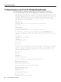
In Figure 4, a small company wants to use Voice over IP to integrate its telephony network with its
existing IP network. The destination pattern (or expanded telephone number) associated with Access
Server 1 (located to the left of the IP cloud) is (408) 555-xxxx, where xxxx identifies the individual
dial peers by extension. The destination pattern (or expanded telephone number) associated with
Access Server 2 (located to the right of the IP cloud) is (729) 411-xxxx.
Voice over IP for the Cisco AS5300 25
Configuration Tasks
Figure 4
Sample Voice over IP Network
729 411-5002
729 411-5003
408 555-1001
729 411-5001
Cisco AS5300
Access
Voice port
Server 1
0:D
WAN
408 555-2001
10.1.1.1
729 411-5004
T1
ISDN PRI
Voice port 0:D
IP
cloud
WAN
10.1.1.2
Cisco AS5300
Access Server 2
10351
1:D
T1 ISDN PRI
408 555-3001
Table 1 shows the number expansion table for this scenario.
Table 1
Sample Number Expansion Table
Extension
Destination Pattern
Num-Exp Command Entry
1...
408555....
num-exp 1... 408555....
2...
408555....
num-exp 2... 408555....
3...
408555....
num-exp 3... 408555....
4...
7294115...
num-exp 4.... 7294115...
Note You can use the period symbol (.) to represent variables (such as extension numbers) in a
telephone number.
The information included in this example needs to be configured on both Router 1 and Router 2.
Configure Number Expansion
To define how to expand an extension number into a particular destination pattern, use the following
command in global configuration mode:
Command
Purpose
num-exp extension-number extension-string
Configures number expansion.
You can verify the number expansion information by using the show num-exp command to display
the telephone number mapping.
26
Cisco IOS Release 12.0(3)T
Configure Dial Peers
After you have configured dial peers and assigned destination patterns to them, you can verify
number expansion information by using the show dialplan number command to learn how a
telephone number maps to a dial peer.
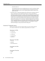
Configure Dial Peers
The key point to understanding how Voice over IP functions is to understand dial peers. Each dial
peer defines the characteristics associated with a call leg, as shown in Figure 5 and Figure 6. Dial
peers are used to apply attributes to call legs and to identify call origin and destination. Attributes
applied to a call leg include QoS, CODEC, VAD, and fax rate. A call leg is a discrete segment of a
call connection that lies between two points in the connection. All of the call legs for a particular
connection have the same connection ID.
An end-to-end call is comprised of four call legs, two from the perspective of the source router or
access server as shown in Figure 5, and two from the perspective of the destination router or access
server as shown in Figure 6. A dial peer is associated with each one of these call legs.
Figure 5
Dial Peer Call Legs from the Perspective of the Source Router or Access
Server
Source
Destination
IP cloud
Call leg for POTS
dial peer 1
Figure 6
10353
Source router
Call leg for VoIP
dial peer 2
Dial Peer Call Legs from the Perspective of the Destination Router or Access
Server
Call leg for VoIP
dial peer 3
Call leg for POTS
dial peer 4
IP cloud
Destination
Source
10354
Destination router
There are two different kinds of dial peers as shown in both Figure 5 and Figure 6:
POTS—POTS dial peers describe the line characteristics usually associated with a traditional
telephony network; in VoIP for the Cisco AS5300, they describe the the specific line characteristics
between the telephony device and the Cisco AS5300. POTS dial peers point to a particular voice port
on a network device—in the case of VoIP for the Cisco AS5300, they point to a specific voice port
on the Cisco AS5300 through which voice traffic will travel to the rest of the voice network.
Voice over IP for the Cisco AS5300 27
Configuration Tasks
VoIP—VoIP dial peers describe the line characteristics usually associated with a packet network
connection (in the case of VoIP, this is an IP network). VoIP peers define the line characteristics
between VoIP devices—the routers and access servers carrying voice traffic in this voice network.
Inbound versus Outbound Dial Peers
Dial peers are used for both inbound and outbound call legs. It is important to remember that these
terms are defined from the access server’s perspective. An inbound call leg originates outside the
access server. An outbound call leg originates from the access server.
For inbound call legs, a dial peer might be associated to the calling number or the port designation.
Outbound call legs always have a dial peer associated with them. The destination pattern is used to
identify the outbound dial peer. The call is associated with the outbound dial peer at setup time.
POTS peers associate a telephone number with a particular voice port so that incoming calls for that
telephone number can be received and outgoing calls can be placed. VoIP peers point to specific
devices (by associating destination telephone numbers with a specific IP address) so that incoming
calls can be received and outgoing calls can be placed. Both POTS and VoIP peers are needed to
establish Voice over IP connections.
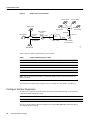
Establishing communication using Voice over IP is similar to configuring an IP static route: you are
establishing a specific voice connection between two defined endpoints. As shown in Figure 7, for
outgoing calls (from the perspective of the POTS dial peer 1), the POTS dial peer establishes the
source (via the originating telephone number or voice port) of the call. The VoIP dial peer establishes
the destination by associating the destination phone number with a specific IP address.
Figure 7
Outgoing Calls from the Perspective of POTS Dial Peer 1
Source
Destination
IP cloud
(408) 526....
10.1.1.2
Voice port
0:D
10355
Source router
Voice port
10.1.2.2
0:D
(310) 520....
POTS call leg
VoIP call leg
To configure call connectivity between the source and destination as illustrated in Figure 7, enter the
following commands on router 10.1.2.2:
dial-peer voice 1 pots
destination-pattern 1408526....
port 0:D
dial-peer voice 2 voip
destination-pattern 1310520....
session target ipv4:10.1.1.2
In the previous configuration example, the last four digits in the VoIP dial peer’s destination pattern
were replaced with wildcards, which means that from router 10.1.2.2, calling any number string that
begins with the digits “1310520” plus four digits will result in a connection to router 10.1.1.2. By
implication, configuring the destination pattern this way means that router 10.1.1.2 services all
numbers beginning with those digits. From router 10.1.1.2, calling any number string that begins
with the digits “1408526” will result in a connection to router 10.1.2.2. By implication, configuring
28
Cisco IOS Release 12.0(3)T
Create a Peer Configuration Table
the destination pattern this way means that router 10.1.2.2 services all numbers beginning with those
digits. For more information about stripping and adding digits, see the “Outbound Dialing on POTS
Peers” section in this document.
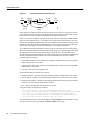
Figure 8 shows how to complete the end-to-end call between dial peer 1 and dial peer 4.
Outgoing Calls from the Perspective of POTS Dial Peer 2
Destination
Source
IP cloud
Destination
router
Voice port
1/0/0
Source
router
10.1.1.2
10.1.2.2
Voice port
1/0/0
408 526....
310 520....
POTS call leg
VoIP call leg
10636
Figure 8
To complete the end-to-end call between dial peer 1 and dial peer 4 as illustrated in Figure 8, enter
the following commands on router 10.1.1.2:
dial-peer voice 4 pots
destination-pattern 1310520....
port 0:D
dial-peer voice 3 voip
destination-pattern 1408526....
session target ipv4:10.1.2.2
Create a Peer Configuration Table
Specific data relative to each dial peer needs to be identified before you can configure dial peers in
Voice over IP. One way to organize this data before you configure VoIP is to create a peer
configuration table.
Using the example in Figure 4, Router 1, with an IP address of 10.1.1.1, connects a small sales
branch office to the main office through Router 2. Three telephones in the sales branch office need
to be connected to Router 1 via the sales office’s PBX. Router 2, with an IP address of 10.1.1.2, is
the primary gateway to the main office; as such, it needs to be connected to the company’s PBX. Four
basic telephone sets need to be connected to Router 2 via the main office’s PBX. Figure 4 shows a
diagram of this small voice network.
Voice over IP for the Cisco AS5300 29
Configuration Tasks
Figure 9
Sample VoIP Network
729 411-5002
729 411-5003
408 555-1001
729 411-5001
408 555-2001
Cisco AS5300
Access
Voice port
Server 1
0:D
WAN
10.1.1.1
729 411-5004
T1
ISDN PRI
Voice port 0:D
IP
cloud
WAN
10.1.1.2
Cisco AS5300
Access Server 2
10351
1:D
T1 ISDN PRI
408 555-3001
Table 2 shows the peer configuration table for the example illustrated in Figure 4.
Table 2
Peer Configuration Table for Sample Voice Over IP Network
Commands
Dial Peer
Tag
Ext
Dest-Pattern
Type
Session-Target
CODEC
QoS
1
1...
+1408555....
POTS
2
2...
+1408555....
POTS
3
3...
+1408555....
POTS
+17294115...
VoIP
IPV4 10.1.1.2
G.729
Best Effort
+1408555....
VoIP
IPV4 10.1.1.1
G.729
Best Effort
+17294115...
POTS
Server 1
10
Server 2
11
4
4...
Configure POTS Peers
POTS peers enable incoming calls to be received by a particular telephony device by defining the
call leg characteristics between the telephony device and the Cisco AS5300. To configure a POTS
peer, you need to uniquely identify the peer (by assigning it a unique tag number), associate the peer
with a voice port through which calls will be established, and define the destination telephone
number(s). Under most circumstances, the default values for the remaining dial peer configuration
commands will be sufficient to establish connections.
30
Cisco IOS Release 12.0(3)T
Configure POTS Peers
To enter the dial peer configuration mode (and select POTS as the method of voice-related
encapsulation), use the following commands in the global configuration mode:
Command
Purpose
dial-peer voice number pots
Enters the dial peer configuration mode to
configure a POTS peer.
The number value of the dial-peer voice pots command is a tag that uniquely identifies the dial peer.
(This number has local significance only.)
To configure the identified POTS peer, use the following commands in the dial peer configuration
mode:
Step
Command
Purpose
1
destination-pattern string
Defines the telephone number associated with this
POTS dial peer.
2
port controller number:D
Associates this POTS dial peer with a specific
logical dial interface.
Outbound Dialing on POTS Peers
When a router receives a voice call, it selects an outbound dial peer by comparing the called number
(the full E.164 telephone number) in the call information with the number configured as the
destination pattern for the POTS peer. The router then strips out the explicit left-justified numbers
corresponding to the destination pattern matching the called number. If you have configured a prefix,
the prefix will be prepended in front of the remaining numbers, creating a dial string, which the
router will then dial. If all numbers in the destination pattern are stripped-out, the user will receive
(depending on the attached equipment) a dial tone.
For example, suppose there is a voice call whose E.164 called number is 1(310) 555-2222. If you
configure a destination pattern of “1310555” and a prefix of “9,” the router will strip out “1310555”
from the E.164 telephone number, leaving the extension number of “2222.” It will then prepend the
prefix “9” to the front of the remaining numbers, so that the actual numbers dialed is “9, 2222.” The
comma in this example means that the router will pause for one second between dialing the “9” and
the “2” to allow for a secondary dial tone.
For additional POTS dial-peer configuration options, refer to the “Command Reference” section in
this document.
Direct Inward Dial for POTS Peers
Direct inward dial (DID) is used to determine how the called number is treated for incoming POTS
call legs. As shown in Figure 10, incoming means from the perspective of the router. In this case, it
is the call leg coming into the access server to be forwarded through to the appropriate destination
pattern.
Voice over IP for the Cisco AS5300 31
Configuration Tasks
PBX
Incoming
call leg
Incoming and Outgoing POTS Call Legs
AS5300
IP
cloud
AS5300
PBX
Outgoing
call leg
10369
Figure 10
Unless otherwise configured, when a call arrives on the access server, the server presents a dial tone
to the caller and collects digits until it can identify the destination dial peer. After the dial peer has
been identified, the call is forwarded through the next call leg to the destination.
There are cases where it might be necessary for the server to use the called number (DNIS) to find a
dial peer for the outgoing call leg—for example, if the switch connecting the call to the server has
already collected the digits. DID enables the server to match the called number with a dial peer and
then directly place the outbound call. With DID, the server does not present a dial tone to the caller
and does not collect digits; it forwards the call directly to the configured destination.
To use DID and incoming called-number, a dial peer must be associated with the incoming call leg.
Before associating the dial peer with the incoming call leg, it helps if you understand the logic behind
the algorithm used to associate the incoming call leg with the dial peer. The algorithm used to
associate incoming call legs with dial peers uses three inputs (which are derived from signalling and
interface information associated with the call) and four defined dial peer elements. The three
signalling inputs are as follows:
•
Called number (DNIS)—Set of numbers representing the destination, which is derived from the
ISDN setup message or CAS DNIS.
•
Calling number (ANI)—Set of numbers representing the origin, which is derived from the ISDN
setup message or CAS DNIS.
•
Voice port—The voice port carrying the call.
The four defined dial peer elements are as follows:
•
•
•
Destination pattern—A pattern representing the phone numbers to which the peer can connect.
•
Port—The port through which calls to this peer are placed.
Answer address—A pattern representing the phone numbers from which the peer can connect.
Incoming called number—A pattern representing the phone numbers that associate an incoming
call leg to a peer based on the called number or DNIS.
Using the elements, the algorithm is as follows:
For all peers where call type (VoIP versus POTS) match dial peer type:
if the type is matched, associate the called number with the incoming called-number
else if the type is matched, associate calling-number with answer-address
else if the type is matched, associate calling-number with destination-pattern
else if the type is matched, associate voice port to port
This algorithm shows that if a value is not configured for answer-address, the origin address is used
because, in most cases, the origin address and answer-address are the same.
32
Cisco IOS Release 12.0(3)T
Configure VoIP Peers
To configure DID for a particular POTS dial peer, use the following commands beginning in global
configuration mode:
Step
Command
Purpose
1
dial-peer voice number pots
Enters the dial peer configuration mode to
configure a POTS peer.
2
direct-inward-dial
Specifies direct inward dial for this POTS peer.
Note Direct inward dial is configured for the calling POTS dial peer.
For additional POTS dial peer configuration options, refer to the “Command Reference” section of
this document.
Configure VoIP Peers
VoIP peers enable outgoing calls to be made from a particular telephony device by defining the line
characteristics between the transmitting and receiving Cisco AS5300s. To configure a VoIP peer, you
need to uniquely identify the peer (by assigning it a unique tag number), define its destination
telephone number and destination IP address. As with POTS peers, under most circumstances, the
default values for the remaining dial peer configuration commands will be adequate to establish
connections.
To enter the dial-peer configuration mode (and select VoIP as the method of voice-related
encapsulation), use the following command beginning in global configuration mode:
Command
Purpose
dial-peer voice number voip
Enters the dial peer configuration mode to
configure a VoIP peer.
The number value of the dial-peer voice voip command is a tag that uniquely identifies the dial peer.
To configure the identified VoIP peer, use the following commands in the dial-peer configuration
mode:
Step
Command
Purpose
1
destination-pattern string
Defines the destination telephone number
associated with this VoIP dial peer.
2
session-target {ipv4:destination-address |
dns:host-name}
Specifies a destination IP address for this dial peer.
For additional VoIP dial peer configuration options, refer to the “Commands” section of this
document. For examples of how to configure dial peers, refer to the “Configuration Examples”
section of this document.
Voice over IP for the Cisco AS5300 33
Configuration Tasks
Verify the Dial Peer Configuration
You can check the validity of your dial peer configuration by performing the following tasks:
•
If you have relatively few dial peers configured, you can use the show dial-peer voice command
to verify that the data configured is correct. Use this command to display a specific dial peer or
to display all configured dial peers.
•
Use the show dialplan number command to show the dial peer to which a particular number
(destination pattern) resolves.
Tips
If you are having trouble connecting a call and you suspect the problem is associated with dial peer
configuration, you can try to resolve the problem by performing the following tasks:
•
Ping the associated IP address to confirm connectivity. If you cannot successfully ping your
destination, refer to the “Configuring IP” chapter in the Cisco IOS 12.0 Network Protocols
Configuration Guide, Part 1.
•
•
Use the show dial-peer voice command to verify that the operational status of the dial peer is up.
•
If you have configured number expansion, use the show num-exp command to check that the
partial number on the local router maps to the correct full E.164 telephone number on the remote
router.
•
If you have configured a CODEC value, there can be a problem if both VoIP dial peers on either
side of the connection have incompatible CODEC values. Make sure that both VoIP peers have
been configured with the same CODEC value.
•
•
•
•
Use the debug vpm spi command to verify that the output string the router dials is correct.
Use the show dialplan number command on the local and remote routers to verify that the data
is configured correctly on both.
Use the debug cch323 rtp command to check RTP packet transport.
Use the debug cch323 h245 command to check logical channel negotiation.
Use the debug cch323 h225 command to check the call setup.
Distinguish Voice and Modem Calls on the Cisco AS5300
When the Cisco AS5300 is handling both modem and voice calls, it needs to be able to identify the
service type of the call—that is, whether the incoming call to the server is a modem or a voice call.
In a mixed environment, where the server receives both modem and voice calls, you need to identify
the service type of the call. You can identify the service type of the call in one of two ways:
•
Configure the incoming called-number command on the voice dial peer associated with the
interface over which the call comes in
•
Assign the called-number to a modem pool.
It helps to understand the logic behind the algorithm the system uses to distinguish voice and modem
calls. The algorithm is as follows:
If the called-number matches a number from the modem pool,
handle the call as a modem call
If the called-number matches a configured dial peer incoming called number,
handle the call as a voice call
Else handle the call as a modem call by default modem pool
34
Cisco IOS Release 12.0(3)T
Optimize Dial Peer and Network Interface Configurations
If there is no called number information provided within the call setup, call classification is handled
as follows:
If there is a modem available in the system-default modem pool
handle the call by a modem from this pool.
Else handle the call as a voice call (either ise the voice dial peer assigned to the
interface over which the call has arrived or use the default dial peer 0).
To identify the service type of a call to be voice, use the following commands beginning in global
configuration mode:
Step
Command
Purpose
1
dial-peer voice number pots
Enters the dial peer configuration mode to
configure a POTS peer.
2
incoming called-number number
Specifies direct inward dial for this POTS peer.
Optimize Dial Peer and Network Interface Configurations
Depending on how you have configured your network interfaces, you might need to configure
additional VoIP dial peer parameters. This section describes the following topics:
•
•
•
Configure IP Precedence for Dial Peers
Configure RSVP for Dial Peers
Configure CODEC and VAD for Dial Peers
Configure IP Precedence for Dial Peers
If you want to give real-time voice traffic a higher priority than other network traffic, you can weight
the voice data traffic associated with a particular VoIP dial peer by using IP Precedence. IP
Precedence scales better than RSVP but provides no admission control.
To give real-time voice traffic precedence over other IP network traffic, use the following commands
beginning in global configuration mode:
Step
Command
Purpose
1
dial-peer voice number voip
Enter the dial peer configuration mode to configure
a VoIP peer.
2
ip precedence number
Select a precedence level for the voice traffic
associated with that dial peer.
In IP Precedence, the numbers 1 through 5 identify classes for IP flows; the numbers 6 and 7 are used
for network and backbone routing and updates.
For example, to ensure that voice traffic associated with VoIP dial peer 103 is given a higher priority
than other IP network traffic, enter the following:
dial-peer voice 103 voip
ip precedence 5
In this example, when an IP call leg is associated with VoIP dial peer 103, all packets transmitted to
the IP network via this dial peer will have their precedence bits set to 5. If the networks receiving
these packets have been configured to recognize precedence bits, the packets will be given priority
over packets with a lower configured precedence value.
Voice over IP for the Cisco AS5300 35
Configuration Tasks
Configure RSVP for Dial Peers
If you have configured your WAN or LAN interfaces for RSVP, you must configure the QoS for any
associated VoIP peers. To configure QoS for a selected VoIP peer, use the following commands
beginning in global configuration mode:
Step
Command
Purpose
1
dial-peer voice number voip
Enters the dial peer configuration mode
to configure a VoIP peer.
2
req-qos [best-effort | controlled-load | guaranteed-delay]
Specifies the desired quality of service to
be used.
Note Cisco suggests that you select controlled-load for the requested quality of service.
For example, to specify guaranteed delay QoS for VoIP dial peer 108, enter the following:
Dial-peer voice 108 voip
destination-pattern +1408528
req-qos controlled-load
session target ipv4:10.0.0.8
In this example, every time a connection is made through VoIP dial peer 108, an RSVP reservation
request is made between the local router, all intermediate routers in the path, and the final destination
router.
To generate an SNMP trap message if the reserved QoS is less than the configured value for a
selected VoIP peer, use the following commands beginning in the global configuration mode:
Step
Command
Purpose
1
dial-peer voice number voip
Enters the dial peer configuration
mode to configure a VoIP peer.
2
acc-qos [best-effort | controlled-load | guaranteed-delay]
Specifies the QoS value below
which an SNMP trap will be
generated.
Note RSVP reservations are only one-way. If you configure RSVP, the VoIP dial peers on both ends
of the connection must be configured for RSVP.
Configure CODEC and VAD for Dial Peers
Coder-decoder (CODEC) and voice activity detection (VAD) for a dial peer determine how much
bandwidth the voice session uses. CODEC typically is used to transform analog signals into a digital
bit stream and digital signals back into analog signals—in this case, it specifies the voice coder rate
of speech for a dial peer. VAD is used to disable the transmission of silence packets.
36
Cisco IOS Release 12.0(3)T
Configure Voice over IP for Microsoft NetMeeting
Configure CODEC for a VoIP Dial Peer
To specify a voice coder rate for a selected VoIP peer, use the following commands beginning in
global configuration mode:
Step
Command
Purpose
1
dial-peer voice number voip
Enters the dial peer configuration mode to
configure a VoIP peer.
2
codec [g711alaw | g711ulaw | g729r8]
Specifies the desired voice coder rate of speech.
The default for the codec command is g729r8; normally the default configuration for this command
is the most desirable. If, however, you are operating on a high bandwidth network and voice quality
is of the highest importance, you should configure the codec command for G711 A Law or
G711 U Law. Using either of these values will result in better voice quality, but it will also require
higher bandwidth requirements for voice.
For example, to specify a CODEC rate of G.711A Law for VoIP dial peer 108, enter the following:
dial-peer voice 108 voip
destination-pattern +1408528
codec g711alaw
session target ipv4:10.0.0.8
Configure VAD for a VoIP Dial Peer
To disable the transmission of silence packets for a selected VoIP peer, use the following commands
beginning in global configuration mode:
Step
Command
Purpose
1
dial-peer voice number voip
Enters the dial peer configuration mode to
configure a VoIP peer.
2
vad
Disables the transmission of silence packets
(enabling VAD).
The default for the vad command is enabled; normally the default configuration for this command
is the most desirable. If you are operating on a high bandwidth network and voice quality is of the
highest importance, you should disable vad. Disabling VAD will result in better voice quality, but it
will also require higher bandwidth requirements for voice.
For example, to enable VAD for VoIP dial peer 108, enter the following:
dial-peer voice 108 voip
destination-pattern +1408528
vad
session target ipv4:10.0.0.8
Configure Voice over IP for Microsoft NetMeeting
Voice over IP can be used with Microsoft NetMeeting (Version 2.x) when the Cisco AS5300 is used
as the voice gateway. Use the latest version of DirectX drivers from Microsoft on your PC to improve
the voice quality of NetMeeting.
Voice over IP for the Cisco AS5300 37
Configuration Tasks
Configure Voice over IP to Support Microsoft NetMeeting
To configure Voice over IP to support NetMeeting, create a VoIP peer that contains the following
information:
•
•
Session Target—IP address or DNS name of the PC running NetMeeting
CODEC—G711 U Law or G711 A Law
Configure Microsoft NetMeeting for Voice Over IP
To configure NetMeeting to work with Voice over IP, perform the following steps in the order given:
1 From the Tools menu in the NetMeeting application, select Options. NetMeeting will display the
Options dialog box.
2 Click the Audio tab.
3 Click the Calling a telephone using NetMeeting check box.
4 Enter the IP address of the Cisco AS5300 in the IP address field.
5 Under General, click Advanced.
6 Click the Manually configured compression settings check box.
7 Select the CODEC value CCITT ulaw 8000Hz.
8 Click the Up button until this CODEC value is at the top of the list.
9 Click OK to exit.
Initiate a Call Using Microsoft NetMeeting
To initiate a call using Microsoft NetMeeting, perform the following steps in the order given:
1 Click the Call icon from the NetMeeting application. Microsoft NetMeeting will open the call
dialog box.
2 From the Call dialog box, select call using H.323 gateway.
3 Enter the telephone number in the Address field.
4 Click Call to initiate a call to the Cisco AS5300 from Microsoft NetMeeting.
VFC Management
VFCs come with a single bundled image of VCWare stored in VFC Flash memory. Table 3 shows
the extension types defined for these embedded firmware files.
38
Cisco IOS Release 12.0(3)T
Download VCWare
Table 3
VFC Firmware Extensions
Firmware
Filenames
Description
VCWare
vcw-vfc-*
Latest version of VCWare stores in Flash memory,
including:
• Datapath engine
• Message dispatcher
• DSP manager
• VC manager
• Process scheduler
DSPWare
btl-vfc-*
DSP bootloader
cor-vfc-*
Core operating system and initialization
bas-vfc-*
Base voice
cdc-*-*
Voice CODEC files
fax-vfc-*
Fax relay files
DSPWare is stored as a compressed file within VCWare; you must unbundle VCWare to install
DSPWare into Flash memory. During the unbundling process, two default lists (the default file list
and the capability list) are automatically created, populated with default files from that version of
VCWare, and stored in VFC Flash memory. The default file list contains the filenames indicating
which files are initially loaded into DSP upon bootup. The capability list defines the set of CODECs
that can be negotiated for a voice call.
VFC management enables you to add versions of VCWare to Flash memory (download and
unbundle files), erase files contained in Flash memory, add files to the default file list and capability
list, and delete files from the default file lists and capability lists.
This section describes the following topics:
•
•
•
•
•
•
•
Download VCWare
Copy Flash Files to the VFC
Unbundle VCWare
Add Files to the Default File List
Add CODECs to the Capability List
Delete Files from VFC Flash Memory
Erase the VFC Flash Memory
Download VCWare
To download software to your VFC, you need to do the following:
•
Determine that the version of VFC ROM Monitor software is compatible with your installed
Cisco IOS image. VFC ROM version 1.2 requires Cisco IOS image 0.14.1 (1.6 NA1) or later.
VFC ROM Monitor version 1.2 can be made to work with Cisco IOS image 0.13 (or later) by
appending the suffix “.VCW” to the VCWare image stored in VFC Flash memory.
•
Determine whether the VFC is in VCWare mode or ROM Monitor mode. The mode, whether
VCWare or ROM Monitor, determines how you download software to the VFC.
•
Download the software using the appropriate procedure.
Voice over IP for the Cisco AS5300 39
Configuration Tasks
Determine the Number of VFCs
To determine the number of installed VFCs and their location, use the following commands in
privileged EXEC mode:
Command
Purpose
show vfc slot directory
Determines the number of installed VFCs and their
location.
For each VFC identified and located, perform the tasks described described in the following sections
to upgrade system software on that VFC.
Identify the VFC Mode
To identify the mode (whether VCWare or ROM Monitor), use the following commands in
privileged EXEC mode:
Command
Purpose
show vfc slot board
Determines whether you VFC is operating in
VCWare mode or ROM Monitor mode.
If the mode is VCWARE, the VFC status will be “VCWARE running.” If the mode is ROM Monitor,
the VFC status will be “ROMMON.”
Download Software (VCWare Mode)
To download VFC software to the VFC while the VFC is in VCWare mode, use the following
commands beginning in privileged EXEC mode:
Step
Command
Purpose
1
erase vfc slot
Erases the Flash memory.
2
show vfc slot directory
Verifies that the VFC Flash memory is indeed
empty.
3
copy tftp vfc
Downloads the VCWare from a TFTPBoot server
into VFC Flash memory
or
Downloads the VCWare from the VFC
motherboard into VFC Flash memory.
copy flash vfc
4
clear vfc slot
Reboots the VFC.
5
show vfc slot board
Checks to see if the VFC is back up in VCWare
mode.
6
show vfc slot directory
Verifies that VCWare is in the VFC Flash.
7
unbundle vfc slot
Unbundles the DSPWare from the VCWare and
configures the default file list and the capability list.
8
show vfc slot directory
Verifies that the DSPWare has been unbundled.
9
show vfc slot default-list
Verifies that the default file list has been populated.
10
show vfc slot cap-list
Verifies that the capability list has been populated.
After you have completed the preceding tasks, reboot the Cisco AS5300 for these changes to take
effect.
40
Cisco IOS Release 12.0(3)T
Copy Flash Files to the VFC
Note If the VFC ROM is version 1.1, the image name must end in “.VCW.” If the VFC ROM is
version 1.2, the image name must start with “vcv-.”
Download Software (ROM Monitor Mode)
To download VFC software to the VFC while the VFC is in ROM Monitor mode, perform the
following tasks, beginning in privileged EXEC mode:
Step
Command
Purpose
1
clear vfc slot purge
Erase the VFC Flash memory.
2
copy tftp vfc
Download the VCWare from a TFTP server into
VFC Flash memory
or
Download the VCWare from the VFC motherboard
into VFC Flash memory.
copy flash vfc
3
clear vfc slot
Reboot the VFC.
4
show vfc slot board
Check to see if the VFC is back up in VCWare
mode.
5
show vfc slot directory
Verify that VCWare is in the VFC Flash.
6
unbundle vfc slot
Unbundle the DSPWare from the VCWare and
configure the default file list and the capability list.
7
show vfc slot directory
Verify that the DSPWare has been unbundled.
8
show vfc slot default-list
Verify that the default file list has been populated.
9
show vfc slot cap-list
Verify that the capability list has been populated.
After you have completed the preceding tasks, reboot the Cisco AS5300 for these changes to take
effect.
Note The image name must start with “vcw-.”
Copy Flash Files to the VFC
As mentioned, each VFC comes with a single bundled image of VCWare stored in Flash memory.
Voice over IP for the AS5300 offers two different ways to copy new versions of VCWare to the VFC
Flash memory: either by downloading the image from the AS5300 motherboard or by downloading
the VCWare from a TFTP server.
Download VCWare to the VFC from the AS5300 Motherboard
To download the VCWare file from the AS5300 motherboard to VFC Flash memory, use the
following command in privileged EXEC mode:
Command
Purpose
copy flash vfc
Downloads (copies) the Flash file from the AS5300
motherboard to the Flash memory on the VFC.
Voice over IP for the Cisco AS5300 41
Configuration Tasks
Download VCWare to the VFC from a TFTP Server
To download the latest version of VCWare from a TFTP server, make sure that the file is stored on
the TFTP server. If you have a copy of the current version of VCWare on disk, you must store that
image on a TFTP server before you can download the file to VFC memory.
To copy the Flash file from a TFTP server, use the following command in privileged EXEC mode:
Command
Purpose
copy tftp vfc
Downloads (copies) the Flash file from a TFTP
server to the Flash memory on the VFC.
Unbundle VCWare
VCWare needs to be unbundled for DSPWare to be loaded in Flash memory and the two necessary
default lists (default file list and capability list) created and populated with the appropriate default
files for that version of DSPWare. Table 4 shows the files associated with each firmware file.
Table 4
VFC Firmware Filenames
Firmware
Filenames
VCWare
vcw-vfc-mz.0.15.bin
DSPWare Initialization
and Static Files
btl-vfc-1.0.14.0.bin
cor-vfc-1.0.14.0.bin
jbc-vfc-1.0.14.0.bin
DSPWare Overlay Files
bas-vfc-1.0.14.0.bin
cdc-g711-1.0.14.0.bin
cdc-g729-1.0.14.0.bin
fax-vfc-1.0.14.0.bin
To unbundle the current running image of VCWare, use the following command in privileged EXEC
mode:
Command
Purpose
unbundle vfc slot
Unbundles the current image of VCWare.
Add Files to the Default File List
When you unbundle VCWare, the default file list is automatically created and populated with the
default files for that version of VCWare. The default file list indicates which files are initially loaded
into DSP upon bootup. The following example shows you the output from the show vfc def
command, which displays the contents of the default file list:
router#show vfc 1 def
Default List for VFC in slot 1:
1. btl-vfc-1.0.13.0.bin
2. cor-vfc-1.0.1.bin
3. bas-vfc-1.0.1.bin
4. cdc-g729-1.0.1.bin
5. fax-vfc-1.0.1.bin
6. jbc-vfc-1.0.13.0.bin
42
Cisco IOS Release 12.0(3)T
Add CODECs to the Capability List
Under most circumstances, these default files should be sufficient. If you need to, you can add an
additional file (from those stored in VFC Flash memory) to the default file list or replace an existing
file from the default file list. When you add a specific file to the default file list, it replaces the existing
default for that extension type.
To select a file to be added to the default file list, use the following command in global configuration
mode:
Command
Purpose
default-file vfc
Selects a file stored in the Flash memory to be
added to the default file list.
Add CODECs to the Capability List
The capability list defines the set of CODECs that can be negotiated for a voice call. Like the default
file list, the capability list is created and populated when VCWare is unbundled and DSPWare added
to VFC Flash memory. The following example shows you the output from the show vfc cap
command, which displays the contents of the capability list:
router#show vfc 1 cap
Capability List for VFC in slot 1:
1. fax-vfc-1.0.1.bin
2. bas-vfc-1.0.1.bin
3. cdc-g729-1.0.1.bin
4. cdc-g711-1.0.1.bin
5. cdc-g726-1.0.1.bin
6. cdc-g728-1.0.1.bin
7. cdc-gsmfr-1.0.1.bin
VFC management lets you add additional CODEC files to the capability list to meet the needs of
your specific telephony network.
Note The capability list does not indicate CODEC preference; it simply reports the CODECs that
are available. The session application decides which CODEC to use.
To add a CODEC overlay file to the capability list, use the following command in global
configuration mode:
Command
Purpose
cap-list file-name vfc slot-number
Selects a codec overlay file to be added to the
capability list.
Delete Files from VFC Flash Memory
In some instances, you might need to delete a file from the default file list or the capability list or you
might need to revert to a previous version of VCWare stored in Flash memory. To delete a file, you
must identify and delete the file from VFC Flash memory. Deleting a file from Flash memory
removes the file from the default file list and capability list (if the deleted file is included on those
lists).
Voice over IP for the Cisco AS5300 43
Configuration Tasks
To delete a file from VFC Flash memory, use the following command in privileged EXEC mode:
Command
Purpose
delete file-name vfc slot
Deletes a specific file from the Flash memory on
the VFC.
Erase the VFC Flash Memory
When you upgrade to a later version of VCWare, the new files are stored in VFC Flash, along with
those already stored in VFC Flash memory—the new files do not overwrite existing files.
Consequently, you will eventually need to erase the contents of VFC Flash memory to free VFC
Flash memory space. Erasing VFC Flash memory removes the entire contents stored in Flash
memory, including the default file list and the capability list.
To erase the Flash memory of a specific VFC, use the following command in privileged EXEC
mode:
Command
Purpose
erase vfc slot
Erases the Flash memory on the VFC.
For more information about VFC management commands, refer to the “Command Reference”
section of this document.
Declarations, Notices, and Network-Related Comments
Notice to Customers In certain countries, use of these products or provision of voice telephony
over the Internet may be prohibited and/or subject to laws, regulations, or licenses, including
requirements applicable to the use of the products under telecommunications and other laws and
regulations; customer must comply with all such applicable laws in the country(ies) where customer
intends to use the product.
44
Cisco IOS Release 12.0(3)T
Linking PBX Users to a T1 ISDN PRI Interface Example
Configuration Examples
This section provides sample configurations for the following scenarios:
•
•
•
Linking PBX Users to a T1 ISDN PRI Interface Example
Configuring Voice over IP for E1 R2 Signalling Example
Configuring Voice over IP for T1-CAS Example
These configuration examples should give you a starting point in your configuration process. The
actual Voice over IP configuration procedure you complete depends on the topology of your voice
network. These configuration examples need to be customized to reflect your network topology.
Linking PBX Users to a T1 ISDN PRI Interface Example
This example describes how to configure Voice over IP to link PBX users with T1 channels
configured for ISDN PRI signalling. In this example, the company has already established a working
IP connection between its two remote offices, one in San Jose, California and the other in Research
Triangle Park (RTP), North Carolina. Figure 11 illustrates the topology of this example.
Figure 11
Linking PBX Users to a T1 ISDN PRI Interface Example
729 411-5002
729 411-5003
408 555-1001
729 411-5001
10.1.1.1
1:D
T1 ISDN PRI
Voice port 0:D
IP
cloud
WAN
10.1.1.2
Cisco AS5300
Access Server 2
10351
408 555-2001
Cisco AS5300
Access
Voice port
Server 1
0:D
WAN
729 411-5004
T1
ISDN PRI
408 555-3001
Each office has an internal telephone network using PBX, connected to the voice network by T1
interfaces. The San Jose office, located to the left of the IP cloud, has two T1 connections; the RTP
office, located to the right of the IP cloud, has only one. Both offices are using PRI signalling for the
T1 connections.
To reach a destination in RTP, users in San Jose pick up the handset, hear a primary dial tone, then
dial 9, 411, and the destination extension number. To reach a destination in San Jose, users in RTP
pick up the handset, hear a primary dial tone, then dial 4. After dialing 4, users hear a secondary dial
tone. The users then dial 555, and the extension number.
Voice over IP for the Cisco AS5300 45
Configuration Examples
Configuration for San Jose Access Server
The first part of this configuration example defines dial-in access, including configuring the T1 lines
and the ISDN D-channel parameters. For more information about configuring ISDN PRI, refer to the
“Configuring Channelized E1 and Channelized T1” chapter in the Cisco IOS Release 12.0 Dial
Solutions Configuration Guide.
hostname sanjose
!
! Define the telephone company’s switch type
isdn switch-type primary-5ess
!
! Configure T1 PRI for line 1
controller T1 0
framing esf
clock source line primary
linecode b8zs
pri-group timeslots 1-24
!
! Configure T1 PRI for line 2
controller T1 1
framing esf
clock source line secondary
linecode b8zs
pri-group timeslots 1-24
!
! Configure the ISDN D channel for each ISDN PRI line
! Serial interface 0:23 is the D channel for controller T1 0
!
interface Serial0:23
isdn incoming-voice modem
!
! Serial interface 1:23 is the D channel for controller T1 1
interface Serial1:23
isdn incoming-voice modem
The next part of this example configures number expansion:
! Configure number expansion.
num-exp 555.... 1408555....
num-exp 4115... 17294115...
The next part of this example configures the POTS and VoIP dial peers:
! Configure POTS dial peer 1 using the first T1
dial-peer voice 1 pots
prefix 6
dest-pat 1408555....
port 0:D
!
! Configure POTS dial-peer 2 using the first T1
dial-peer voice 2 pots
prefix 7
dest-pat 1408555....
port 0:D
!
46
Cisco IOS Release 12.0(3)T
Configuration for RTP Access Server
! Configure POTS dial-peer 3 using the second T1
dial-peer voice 3 pots
prefix 5
dest-pat 1408555....
port 1:D
!
! Configure VoIP dial-peer 4
dial-peer voice 4 voip
dest-pat 17294115...
session-target ipv4:10.1.1.2
Configuration for RTP Access Server
The first part of this configuration example defines dial-in access, including configuring the T1 line
and the ISDN D-channel parameters. For more information about configuring ISDN PRI, refer to the
“Configuring Channelized E1 and Channelized T1” chapter in the Cisco IOS Release 12.0 Dial
Solutions Configuration Guide.
hostname rtp
! Define the telephone company’s switch type
isdn switch-type primary-5ess
! Configure T1 PRI for line 1
controller T1 0
framing esf
clock source line primary
linecode b8zs
pri-group timeslots 1-24
!
! Configure the ISDN D channel for ISDN PRI line 1
! Serial interface 0:23 is the D channel for controller T1 0
interface Serial0:23
ip address 7.1.1.10 255.255.255.0
encapsulation ppp
isdn incoming-voice modem
dialer-group 1
ppp authentication chap
The next part of this example configures number expansion:
! Configure number expansion.
num-exp 555.... 1408555....
num-exp 4115... 17294115...
The next part of this configuration example defines the POTS and VoIP peers:
! Configure POTS dial-peer 1
dial-peer voice 1 pots
dest-pat 17294115...
port 0:D
!
! Configure VoIP dial-peer 5
dial-peer voice 4 voip
dest-pat 1408555....
session-target ipv4:10.1.1.1
Voice over IP for the Cisco AS5300 47
Configuration Examples
Configuring Voice over IP for E1 R2 Signalling Example
The following example configures R2 signalling and customizes R2 parameters on controller E1 2
of a Cisco AS5300. In most cases, the same R2 signalling type is configured on each E1 controller.
! Specify the E1 controller that you want to configure with R2 signalling. A controller
! informs the access server how to distribute or provision individual timeslots for a
! connected channelized E1 line. You must configure one E1 controller for each E1 line.
! Configure channel associated signalling. The signalling type forwarded by the
! connecting telco switch must match the signalling configured on the Cisco AS5300.
! The country code is ITU by default.
!
controller E1 0
framing NO-CRC4
cas-group 0 timeslots 1-15,17-31 type r2-digital r2-compelled ani
cas-custom 0
!
controller E1 1
framing NO-CRC4
clock source line primary
cas-group 0 timeslots 1-15,17-31 type r2-digital r2-compelled
!
! Customize some of the E1 R2 signalling parameters with the cas-custom channel
! controller configuration command. This example specifies the default R2 settings for
! Brazil.
!
cas-custom 0
country brazil use-defaults
metering
category 2
answer-signal group-b 1
!
controller E1 2
!
controller E1 3
!
! Configure voice port parameters. Be sure that the cptone command value is compatable
! with the country code defined by the cas-custom command. In this example, because
! ITU has no specific cptone value defined and uses aLaw E1 R2 signalling, the GB
! cptone command value is used.
!
voice-port 0:0
cptone GB
!
voice-port 1:0
cptone BR
description Brasil Tone
!
! Define the parameters associated with the VoIP dial peer.
!
dial-peer voice 101 voip
destination-pattern +500..
session target ipv4:172.14.25.1
!
! Define the parameters associated POTS dial peer.
!
dial-peer voice 8221 pots
destination-pattern 011822...
direct-inward-dial
port 0:0
!
! Configure LAN interfaces.
!
interface Ethernet0
ip address 172.13.103.33 255.255.0.0
48
Cisco IOS Release 12.0(3)T
Configuring Voice over IP for T1-CAS Example
no ip directed-broadcast
no ip mroute-cache
load-interval 30
no cdp enable
!
interface FastEthernet0
ip address 173.14.25.100 255.255.0.0
no ip directed-broadcast
bandwidth 1000000
load-interval 30
duplex full
hold-queue 75 in
!
no ip classless
ip route 223.255.254.253 255.255.255.255 Ethernet0
!
!
line con 0
exec-timeout 0 0
logging synchronous level all
transport input none
escape-character BREAK
line aux 0
rotary 1
transport preferred none
transport input all
flowcontrol hardware
line vty 0 4
exec-timeout 60 0
password lab
login
!
end
Note Cisco strongly recommends that you specify your country’s default settings. To display a list
of supported countries, enter the country ? command under the cas-custom command. The default
setting for all countries is ITU.
Configuring Voice over IP for T1-CAS Example
The following example configures T1 CAS parameters on a Cisco AS5300:
! Enter global configuration mode.
config terminal
! Enter controller configuration mode to configure your controller port. The controller
ports are labeled 0 through 3 on the Quad T1/PRI and E1/PRI cards.
controller t1 0
! Enter your telco’s framing type.
framing esf
! Enter the clock source for the line. Configure other lines as clock source secondary
! or internal. Note that only one PRI can be clock source primary and one PRI can be
! clock source secondary
clock source line primary
! Enter your telco’s line code type.
linecode b8zs
! Configure all channels for E&M, FXS, and SAS analog signalling. Enter 1-24 for T1.
! If E1, enter 1-31.
! Signalling types include e&m-fgb, e&m-fgd, e&m-immediate-start, fxs-ground-start,
! fxs-loop-start, sas-ground-start, and sas-loop-start.
! You must use the same type of signalling that your central office uses.
! For E1 using the Anadigicom converter, use cas e&m-fgb signalling.
Voice over IP for the Cisco AS5300 49
Configuration Examples
cas-group 1 timeslots 1-24 type e&m-fgb dtmf dnis
! Configure each additional controller (there are four). In this example, the
! controller number is 1, instead of 0. The clock source is secondary, instead of
! primary. The cas-group is 2, instead of 1
controller t1 1
framing esf
linecode b8Zs
clock source line secondary
cas-group 2 timeslots 1-24 type e&m-fgb
! Configure each additional controller.
controller T1 2
clock source internal
cas-group 0 timeslots 1-24 type e&m-fgd mf ani-dnis
controller T1 3
clock source internal
! Enter the dial peer configuration mode to configure a POTS peer.
! Specify destination pattern for this POTS peer.
dial-peer voice 3070 pots
destination-pattern +30...
port 0:1
prefix 30
! Specify destination pattern, and direct inward dial for each POTS peer.
dial-peer voice 4080 pots
destination-pattern +40...
direct-inward-dial
port 1:2
prefix 40
! Specify the destination pattern and the direct inward dial for the dial peer.
dial-peer voice 1050 pots
destination-pattern +10...
direct-inward-dial
prefix 50
! Specify the destination pattern and the direct inward dial for the dial peer.
dial-peer voice 2060 pots
destination-pattern +20...
direct-inward-dial
prefix 60
dial-peer voice 5050 voip
answer-address 10...
destination-pattern +50...
end
end
50
Cisco IOS Release 12.0(3)T