1
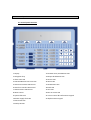
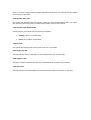
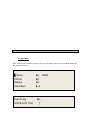
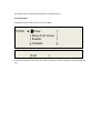
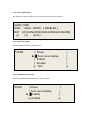
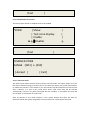
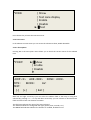
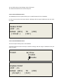
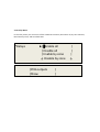
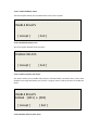
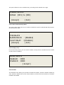
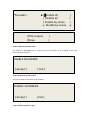
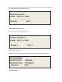
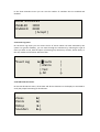
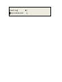
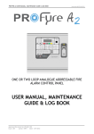
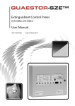
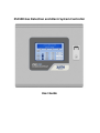
ZSC100 Gas Detection and Alarm System Controller User Guide 1- Introduction ......................................................................................................... 3 1.1- General description ....................................................................................................................... 3 1.2- Cautions and warnings .................................................................................................................. 3 2- Control panel ........................................................................................................ 4 2.1 Control panel overview .................................................................................................................. 4 2.2 Control keys .................................................................................................................................... 5 2.2.1 Alphanumeric keypad (22) .......................................................................................................... 5 2.2.2 Cursor Control keys and confirmation (21) ................................................................................. 5 2.2.3 Silence sounders .......................................................................................................................... 5 2.2.4 Sounders On ................................................................................................................................ 5 2.2.5 Silence Buzzer .............................................................................................................................. 5 2.2.6 Reset ............................................................................................................................................ 5 2.3 LED indications ............................................................................................................................... 5 2.4 Access Levels .................................................................................................................................. 7 3- User menu ............................................................................................................ 8 3.1 Main Menu ..................................................................................................................................... 8 4- Procedure in case of Alarm or Fault..................................................................... 21 5- Maintenance ...................................................................................................... 22 5.1- Function Checks .......................................................................................................................... 22 5.2- Servicing and Panel Repairs ......................................................................................................... 22 1- Introduction 1.1- General description This manual contains instructions for setting up and maintenance of the ZSC100 analogue panel, and technical data. The panel is a single loop system that supports up to 48 devices on the loop. This analogue range is designed to serve medium and large facilities that require a gas detection system, such as businesses, schools, small and medium enterprises, etc This panel should be installed by qualified personnel. 1.2- Cautions and warnings It is important to connect the power supplies in the following order: First, connect the panel to the mains (230 V AC) Secondly, connect the batteries The equipment may be damaged if it is not connected in this order. 2- Control panel 2.1 Control panel overview 1 Display 13 Sounder fault / disablement LED 2 Navigation keys 14 Output disablement LED 3 Alarm zone LED 15 Service LED 4 Fault-disablement-test zone LED 16 Alarm LED 5 Switch off sounder LED-Control 17 Disablement LED 6 Switch on sounder LED-Control 18 Fault LED 7 Silence Buzzer LED-Control 19 Test LED 8 Reset Control 20 Out of service LED 9 System fault LED 21 Cursor Control & Confirmation Keypad 10 Power supply fault LED 22 Alphanumeric Keypad 11 Earth fault LED 12 Delay ON LED 2.2 Control keys 2.2.1 Alphanumeric keypad (22) These keys are used to: Enter text and numbers to programme the system. Directly access the desired menu. 2.2.2 Cursor Control keys and confirmation (21) These keys are used to move between menus and submenus of the system in an agile and quick manner. Selection confirmation is achieved with the OK key. 2.2.3 Silence sounders Pressing this button disables the sounders when triggered. If a new alarm occurs the sounders are activated. After eliminating the alarm by pressing the reset button will return to standby. 2.2.4 Sounders On Pressing this key causes the immediate activation of the sounders. This control overrides any sounder delay that has been programmed. 2.2.5 Silence Buzzer This key silences the buzzer when it is active, and the silence buzzer indicator lights. When the buzzer is re-activated, the silence buzzer indicator turns off. 2.2.6 Reset Pressing this button causes the system to return to the normal condition. 2.3 LED indications 2.3.1 System Fault LED This yellow LED is permanently active when there is any critical situation in the system. In this case the system is not operational. 2.3.2 Power Supply Fault LED This yellow indicator flashes if there is any problem in the power supply, caused by the network, batteries or fuses. 2.3.3 Out of service LED There is no mains supply and the voltage supplied by batteries is not sufficient for the proper functioning of equipment. 2.3.4 Sounder Delay LED This yellow LED indicates that the sounder outputs are time delayed. When there is an alarm the sounder outputs will not be activated until the delay time set has expired. 2.3.5 Sounder Fault/Disabled LED Yellow indicator associated with the outputs of sounders: Flashing: There is a sounder fault. Fixed: The sounders are disabled. 2.3.6 Test LED This yellow LED indicates that some of the zones are in test mode. 2.3.7 Earth Fault LED This flag indicates that at some point in the installation there is an earth fault. 2.3.8 Supply on LED This green indicator indicates that the unit is powered either by mains or by batteries. 2.3.9 Alarm LED This red indicator is activated when the panel detects an alarm at any device on the loop. 2.3.10 Disabled LED This yellow LED indicates that a zone or the sounders in the installation are disabled. If it is the sounders, the sounders fault/disablement LED will also illuminate. 2.3.11 Fault LED This yellow LED is permanently active when any fault occurs in the system. In this case not all of the system is operational. 2.3.12 Disabled LED This yellow indicator is activated when the relay outputs are disabled. It is also activated if a loop relay module is disabled. 2.4 Access Levels The analogue panels have 2 levels of access. Thus we can only access the configuration menus or controls if the proper passcode is entered. Level 1: All indications from the panel are operational, but the unit's controls are locked. Level 2: After entering the appropriate code, you can access the front panel controls. At this level you cannot access the system configuration. 3- User menu 3.1 Main Menu After entering the passcode to level 2, the user navigation menu can be accessed. Below are the navigation menus. █Zones Points Relays Sounders Event Log LED & LCD Test ►| USER ►| ►| ►↓ ►| | The selected menu is always displayed with a flashing asterisk. 3.1.1 ZONE Menu Clicking OK from the main menu, access the ZONE. *ZONE ►|█Show | | Show Test zones | | Enable | ↓ Disable ↓ |Test | In the Zone menu you can access the submenus Show, Test Zone Display, Enable, Disable and Test. 3.1.1.1 Zone display menu The Show menu option allows you to check the current status of the zone. SHOW ZONE ZONE : <001> MODE : [ ENABLED ] TEXT : [012345678901234567890123456789] [-] [+] [Exit ] 3.1.1.2 Test zone display Use this option to see zones being tested. *ZONE | Show ►|█ Test zone display | Enable | Disable ↓ Test 3.1.1.3 Enablement zone menu This menu option allows disabled zones to be enabled. *ZONE | Show | Test zone display ►|█Enable ↓ Disable | | | ↓ | | | | ↓ |Test | 3.1.1.4 Disablement zone menu This menu option allows us enabled zones to be disabled. *ZONE | Show | Test zone display | Enable ►↓█Disable |Test | | | ↓ | DISABLED ZONE RANGE : [001] a [250] [ Accept ] [ Exit ] 3.1.1.5 Test zone menu This option menu allows selected zones to be put into test mode. This option allows us to test the sensors without having to reset the unit. If you select this option, the system asks whether to enable the sounders. If the answer is yes, the sounders will be activated for a few seconds after a detector in a zone in test mode enters alarm, after which they will be silenced automatically. If there is any delay associated with the sounders, in test mode, the delay will be cancelled, to streamline the system test. After 20 minutes of test mode selection, if the system detects that there has been no detectors tested, the system will go back to the normal mode, reversing the test mode. *ZONE | Show | Test zone display | Enable | Disable ►|█Test Press the Exit key to leave the Test Zone menu. 3.1.2 Point menu In the Element or Point menu you can access the submenus Show, Enable & Disable. 3.1.2.1 Show points Pressing OK in the View point menu allows you to check the current status of the selected item. *POINT ►|█Show | Enable | Disable ▼ LOOP:<1> ADR <001> ZONE : <001> TYPE : MODE: AV: TEXT: [-] [+] [ Exit ] With left and right arrow keys you can select the address field of the loop or loop point selected. By pressing <+> <-> or up and down arrow keys you can increase or decrease these fields and move from one element to another. The field zone indicates the zone of the point selected. The TYPE field shows the configured item type (optical, heat, sounder, etc.). The MODE field indicates whether the element is: enabled, disabled or test. The AV field indicates the analogue value of the item. The TEXT field indicates the name of the point. 3.1.2.2 Point enablement menu The ENABLE point menu option allows you to enable elements that are disabled. For this you must enter the loop to which it belongs and the range of addresses that you want to enable. ENABLE POINT LOOP : <1> RANGE : [001] [ Accept ] TO [250] [ Exit ] 3.1.2.3 Point disablement menu This menu option allows points to be disabled. To do this you must enter the loop to which it belongs and the range of addresses that you want to enable. *POINT DISABLE POINT LOOP : <1> RANGE : [001] [ Accept ] ►| Show | Enable |█Disable ▼ TO [250] [ Exit ] 3.1.3 Relay Menu In the relay menu you can access all the submenus Connect, Disconnect all, by zone Connect, Disconnect by zone, and Ver Check PCB *Relays ►|█Enable all | Disable all | Enable by zone ↓ Disable by zone |PCB outputs |Show | | | | | ↓ 3.1.3.1 Enable All Relays menu This menu option allows you to enable all the relays on the system. ENABLE RELAYS [ Accept ] [ Exit ] 3.1.3.2 Disable All Relays menu This menu option disables all of the relays. DISABLE RELAYS [ Accept ] [ Exit ] 3.1.3.3 Enable relays by zone menu This option allows you to enable relay outputs, associated with a particular zone, if they were disabled. The range field allows you to enter a range of zones in which you want to enable the relays. ENABLE RELAYS RANGE : [001] a [001] [ Accept ] [ Exit ] 3.1.3.4 Disable relays by zone menu This option allows the user to disable relays, according to the selected zone range. DISABLE RELAYS RANGE : [001] to [001] [ Accept ] [ Exit ] 3.1.3.5 Alarm and Fault Relays Menu This menu choice allows the user to enable or disable the panel’s onboard PCB relay outputs, the fault and fire relays. PCB RELAYS ALARM RELAY : [ENABLE] FAULT RELAY : [DISABLE] [ Accept ] [ Exit ] 3.1.3.6 Display relays In the show relays menu, you can see the number of relays that are enabled and the number of relays that are disabled. SHOW RELAYS ENABLED :0002 DISABLED :0000 [ Accept ] 3.1.4 Sounders The Sounders menu allows you to enable or disable all sounders, enable or disable sounders by zone, enable or disable each of the 2 PCB sounders, and show the total numbers of sounders enabled and disabled. ►|█Enable all | | Disable all | | Enable by zones | ↓ Disable by zones ↓ *Sounders |PCB outputs |Show | | 3.1.4.1 Enable all sounders menu The enable all SOUNDERS menu option permits all sounders to be enabled if they had previously been disabled. ENABLE SOUNDERS [ Accept ] [ Exit ] 3.1.4.2 Disable all sounders menu This option allows all sounders to be disabled. DISABLE SOUNDERS [ Accept ] 3.1.4.3 Enable sounders by zone [ Exit ] This menu option allows SOUNDERS in specific zones to be enabled if they have been disabled. The range of zones to be enabled is entered. ENABLE SOUNDER RANGE : [001] to [001] [ Accept ] [ Exit ] 3.1.4.4 Disable sounders by zone This allows sounders to be disabled by zone. DISABLE SOUNDER RANGE : [001] a [001] < Accept > < Exit > 3.1.4.5 PCB sounders menu This menu choice allows the internal PCB Sounders Outputs to be enabled or disabled. PCB SOUNDERS SOUNDER ONE : [ENABLE ] SOUNDER TWO : [DISABLE ] [ Accept ] [ Exit ] 3.1.4.6 Show menu In the Show Sounders menu you can see the number of sounders that are enabled and disabled SHOW SOUNDERS ENABLED :0002 DISABLED :0000 [ Accept ] 3.1.5 Event Log menu On the Event Log menu you can access the list of events which has been detected by the system. For greater flexibility, you can move through the submenus by selecting the type of event you want to see, with the option of selecting only the history of faults, alarms alone, or the only evidence of all events without a filter. *Event Log ►|█Faults | Alarms | Test ↓ All | | | ↓ 3.1.6 LED & LCD test menu On the LED & LCD Test menu, all the LEDs and all the characters in the display are activated to verify the proper functioning of all indicators. Zones Points Relays Sounders ►| ►| ►| ►↓ Event Log █Test LED & LCD ►| ↓ 4- Procedure in case of Alarm or Fault The analogue panel is designed to ensure an effective response in case of alarm. It is necessary to know the panel to act correctly in a critical situation. IMPORTANT: You must read the following steps, as it will help in case of alarm: 1. The main thing when there is an alarm is to remain calm, the panel’s sounders that warn of the gas leak may provoke a state of nerves that prevents us from reacting and operating correctly. 2. The authorised user should have the user passcode that gives access to the panel's keyboard control. 3. The authorised user must press the Silence buzzer key to silence the panel’s internal buzzer, and if you want to stop the sounders you must press the silence sounders control. 4. The officer may identify the alarm as the panel’s display will indicate the type of alarm or fault that has occurred in the system. 5. Having identified the cause of the alarm it is time to action the current emergency plan Once the problem has been solved, the panel has to be reset. 5- Maintenance The following do not replace the appropriate care recommendations of relevant codes of practice including those of EN50073 for selection, installation, use and maintenance of apparatus for detection and measurement of combustible gases. 5.1- Function Checks Regularly inspect state of the detection system. During bump-testing, make notes of the response of the control panel to gas alarms. The panel must indicate normal operation. If faults are recorded in the event log, advise the company responsible for maintaining the equipment. 5.2- Servicing and Panel Repairs During any scheduled repairs and servicing of the apparatus, ensure the recommendations of EN 50073 are met. Ensure that safety of the area being monitored is not compromised by providing a duplicate apparatus for continuous monitoring. Working on electrical and electronic equipment requires appropriate technical training. Ensure only trained personnel with required level of knowledge carries out the maintenance work.