1
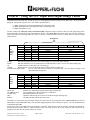
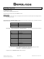
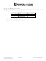
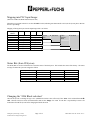
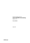
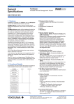
KHD2-MTI-AB4 Allen-Bradley Remote I/O Node Adapter for IDENT-I System P User Manual 2001 Pepperl+Fuchs, Inc. Ÿ 1600 Enterprise Parkway Ÿ Twinsburg, OH 44087 Telephone (330) 425-3555 Ÿ FAX (330) 425-4607 Overview The AB Remote I/O Node Adapter KHD2-MTI-AB4 enables a Pepperl+Fuchs inductive identification system Communicator for Ident-I System P (IPT-PF with base U-P4-Rx) to be treated as a remote rock. For the purpose of this manual, the combination of KHD2-MTI-AB4 and Communicator is referred to as the ID System. Communications between the PLC and ID System is accomplished via Discrete I/O (DIO). KHD2-MTI-AB4 IPT-FT with U-P4-Rx Intelligent System Group (3/15/02) P4-RX with Pre-Configured Support.doc Page 1 of 15 KHD2-MTI-AB4 with IPT-FP and U- Revisions July 2001 Reading of Pre-Configured IPC03-xx tags has been implemented. Reading pre-configured tags is only possible when the node adapter is set for IPC03 type tags and if the Rack Size has been set to ¼ or ½ Rack (see section DIP Switches on the KHD2-MTI-AB4). 2001 The previously manufactures bases U-P3-Rx and U-P3-R4 have been replaced by U-P4-Rx and U-P4-R4. The following changes occurred: U-P3-Rx Interface Threading Intelligent System Group (3/15/02) P4-RX with Pre-Configured Support.doc RS-232 (Compatible with KHD2-MTI-AB4) PG 13.5 Page 2 of 15 U-P3-R4 RS-485 PG 13.5 U-P4-Rx RS-232 (Compatible with KHD2-MTI-AB4) ½” NPT U-P4-R4 RS-485 ½” NPT KHD2-MTI-AB4 with IPT-FP and U- Protocol – Using the PLC Input and Output Image Tables Communication between the PLC and the ID System is accomplished by means of Discrete I/O (DIO) only. At any given time during the operation the system can be in one of three operational states: (1) While scanning for tags and not updating the PLC Input image table (2) While updating the PLC input image table and not scanning for tags (3) While writing data to a tag The PLC instructs the ID System via 8 Communication-Bits, mapped into the lower half of Word 0 of the output image table. Status information from the ID System is transmitted to the PLC via 8 Status-Bits located in the lower half of Word 0 of the PLC input image table The following defines the names of special Communication-Bits and also outlines the PLC input and output image structure. 16 bit Words PLC Output Image table Word 0 Word 1 Word 2 Word 3 Word 4 Word 5 Word 6 Word 7 Nibble 4 Nibble 4 Nibble 4 Nibble 4 Nibble 4 Nibble 4 Nibble 4 Nibble 4 Nibble 3 Nibble 3 Nibble 3 Nibble 3 Nibble 3 Nibble 3 Nibble 3 Nibble 3 4 Bit Block selection Nibble 2 Nibble 2 Nibble 2 Nibble 2 Nibble 2 Nibble 2 Nibble 2 Clear Op Done Nibble 1 Nibble 1 Nibble 1 Nibble 1 Nibble 1 Nibble 1 Nibble 1 Start START: Start transferring data from ID System (when reading) or to ID System (when writing) DONE: Indicates that the PLC user program has processed the data and is ready to receive more data (reading only) OP: Operation OFF for reading tags, ON for writing tags CLEAR: Instructs the ID system to clear all data from its internal buffers (reading only) 4-BIT BLOCK SELECTION: Used to select read and write location on read/write tags. Also used instruct reading a read only FIXCODE (reading only) PLC Input Image table Word 0 Word 1 Word 2 Word 3 Word 4 Word 5 Word 6 Word 7 DATA OK: NT, ERROR, BAT: CLEAR ACK: OPA: EMPTY: Nibble 4 Nibble 4 Nibble 4 Nibble 4 Nibble 4 Nibble 4 Nibble 4 Nibble 4 Nibble 3 Nibble 3 Nibble 3 Nibble 3 Nibble 3 Nibble 3 Nibble 3 Nibble 3 Error Empty 0 Nibble 2 Nibble 2 Nibble 2 Nibble 2 Nibble 2 Nibble 2 Nibble 2 OPA Clear ACK BAT NT Nibble 1 Nibble 1 Nibble 1 Nibble 1 Nibble 1 Nibble 1 Nibble 1 Data OK Indicates PLC input image equal the output image (reading only) No Tag (writing only), Error and battery low indication Internal buffers have been cleared Operation Acknowledge. PLC has received a Write Request (Writing only) No additional data available from ID System The number of words in the input and output image table used by the ID System depends on the selected rack size (selected via DIP-Switches on the HKD2-MTI-AB4). Note that data mapping depends on the selected Start Quarter, selected via DIP-Switches on the KHD2-MTI-AB4. The protocol on the node adapter has been designed to completely shield the user from the specifics of the ID Communicators. Because Ident-I System P utilizes a command subset of the “P+F Talk” protocol, PLC code written for Ident-I System P can typically be used for other ID system offering “P+F Talk”. Intelligent System Group (3/15/02) P4-RX with Pre-Configured Support.doc Page 3 of 15 KHD2-MTI-AB4 with IPT-FP and U- Power-Up When powering-up the HKD2-MTI-AB4 sends the necessary configuration data to the Communicator. Depending on the position of DIP-Switch SW1,1 on the KHD2-MTI-AB4 The system is configured to work with IPC02 (R/O code on tags only) or IPC03 (R/O code and tags plus R/W memory) type tags: Ident-I System P SW1,1 = Off ci003,19200<chk><etx> ct02<chk><etx> rs<chk><etc> SW1,1 = On ci003,19200<chk><etx> ct03<chk><etx> rs<chk><etc> Configure for 19200 baud and 300ms serial timeout. Select to work with IPC02(*) Type R/O code carriers Rest to activate the “ci” settings Configure for 19200 baud and 300ms serial timeout. Select to work with IPC03 Type R/W data carriers Rest to activate the “ci” settings The entire configuration and startup phase takes under 1 second. The ID System will only go online with the RIO Scanner once a Communicator has been found and was properly configured. Once online the green RIO-LED on the KHD2-MTI-AB4 is on solid. See section Trouble Shooting for additional information. In order for the HKD2-MTI-AB4 to perform this configuration, the Communicator must be set to an RS232 baud rate of 9600 baud or 19200 baud. This can be accomplished by one of the following methods: Issue the command ci003,9600#<Enter> using a terminal program at the correct current baud rate of the Communicator. Then power-down and power-up the unit. The default baud rate of Communicators shipped from stock is 9600 baud. (*) This mode also enables reading on IPC10 that have been written using the X-Command. For additional information see P+F Documentation IPT with Base U-P4-Rx or IPT with Base U-P4-R4. Intelligent System Group (3/15/02) P4-RX with Pre-Configured Support.doc Page 4 of 15 KHD2-MTI-AB4 with IPT-FP and U- Reading Tag Data Scanning for Tags (Initial state: START=Off, DONE=Off, OP=Off, Clear=Off) The ID System scans for tags as long as the “START” bit is OFF. IDENT-I System P Scanning takes under 500ms worst case and depends on the selected rack size and the amount of electromagnetic noise in the operating environment. When reading tags the “4 Bit Block selection” is used to specify which memory locations are read. The amount of data read depends on the selected rack size on the HKD2-MTI-AB4: Rack Size Quarter Half Three Quarter Full Quarter Rack Number of Bytes read 03 07 11 15 In this case a data block of 3 bytes is read from the tag. The following table relates the byte location on the tag with the value of the “4 Bit Block selection” Block Selection 0000 0001 0010 0011 0100 0101 0110 0111 1000 1001 1010 1011 1100 1101 1110 1111 Tag Data Bytes (in decimal) 01 through 03 04 through 06 07 through 09 10 through 12 13 through 15 16 through 18 19 through 21 22 through 24 25 through 27 28 through 30 31 through 33 34 through 36 37 through 39 40 through 42 43 through 45 Fixcode The general relation between the “4 Bit Block selection” and the data byte range on the tag is as follows: Start of Range = 1 + Block Selection (in Decimal) * 3 End of range = 3 + Block Selection (in Decimal) * 3 Using IPC03 tags, all “4 Bit Block selection” patterns are allowed. Intelligent System Group (3/15/02) P4-RX with Pre-Configured Support.doc Page 5 of 15 KHD2-MTI-AB4 with IPT-FP and U- Half Rack In this case a data block of 7 bytes is read from the tag. The following table relates the byte location on the tag with the value of the “4 Bit Block selection” Block Selection 0000 0001 0010 Tag Data Bytes (in decimal) 01 through 07 08 through 14 15 through 21 1110 1111 99 through 105 Fixcode The general relation between the “4 Bit Block selection” and the data byte range on the tag is as follows: Start of Range = 1 + Block Selection (in Decimal) * 7 End of range = 7 + Block Selection (in Decimal) * 7 Using IPC03 tags, all “4 Bit Block selection” patterns are allowed. Three Quarter Rack In this case a data block of 11 bytes is read from the tag. The following table relates the byte location on the tag with the value of the “4 Bit Block selection” Block Selection 0000 0001 0010 • • 1001 • • 1110 1111 Tag Data Bytes (in decimal) 01 through 11 12 through 22 23 through 33 • • 100 through 110 (last accessible block on IPC03) • • 155 through 165 Fixcode The general relation between the “4 Bit Block selection” and data byte range on the tag is as follows: Start of Range = 1 + Block Selection (in Decimal) * 11 End of range = 11 + Block Selection (in Decimal) * 11 Using IPC03 tags, the highest “4 Bit Block selection” patterns allowed is 1001. When selecting a higher “4 Bit Block selection” the Communicator is instructed to access tags memory that does not exist. Intelligent System Group (3/15/02) P4-RX with Pre-Configured Support.doc Page 6 of 15 KHD2-MTI-AB4 with IPT-FP and U- Full Rack In this case a data block of 15 bytes is read from the tag. The following table relates the byte location on the tag with the value of the “4 Bit Block selection” Block Selection 0000 0001 0010 • • 0110 • • 1110 1111 Tag Data Bytes (in decimal) 01 through 15 16 through 30 31 through 45 • • 91 through 105 (last accessible block on IPC03) • • 211 through 225 Fixcode The general relation between Block Selection and data byte range on the tag is as follows: Start of Range = 1 + Block Selection (in Decimal) * 15 End of range = 15 + Block Selection (in Decimal) * 15 Using IPC03 tags, the highest “4 Bit Block selection” patterns allowed is 0110. When selecting a higher “4 Bit Block selection” the Communicator is instructed to access tags memory that does not exist. Intelligent System Group (3/15/02) P4-RX with Pre-Configured Support.doc Page 7 of 15 KHD2-MTI-AB4 with IPT-FP and U- Special case: Reading “Fixcodes” The “4 Bit Block selection” pattern 1111 has a special meaning. It causes the node adapter to issue a R/O command. The length of the reply sting depends on the ID system type and tags type as follows ID System Type IDENT-I System P Tag Type IPC02 (Bit 1, Switch 1 OFF IPC03 (Bit 1, Switch 1 ON) IPC10 in IPC02 mode (Bit 1, Switch 1 OFF) data reply length 40 bits of data 32 bits of data 40 bits of data When using ¼ Rack the most significant two bytes of an IPC02 are lost When using ¼ Rack the most significant two bytes of an IPC10 in IPC02 Mode are lost When using ¼ Rack the most significant byte of an IPC03 is lost Intelligent System Group (3/15/02) P4-RX with Pre-Configured Support.doc Page 8 of 15 KHD2-MTI-AB4 with IPT-FP and U- Mapping into PLC Input Image: (Initial state: START=Off, DONE=Off, OP=Off, Clear=Off) When the user program in the PLC sets the “START” bit ON (indicating start data transfer to PLC) the ID System places data into the PLC input image. Mapping of the tag data bytes into the Input image table is as follows PLC Input Word Word-0 Word-1 Word-2 Word-3 Word-4 Word-5 Word-6 Word-7 Remark: Rack Size to # of Tag Bytes relation Byte 1 Byte 3 Byte 5 Byte 7 Byte 9 Byte 11 Byte 13 Byte 15 Communication Byte 2 Byte 4 Byte 6 Byte 8 Byte 10 Byte 12 Byte 14 Quarter Rack Half Rack Three Quarter Rack Full Rack Status Bits (from ID System) The Status Bits are used to inform the PLC about the status of the ID System. This includes the status of the battery. The status messages from the ID system are mapped as follows ID System Status 0 (operation successful) 2, 5 1 (Low bat indication) Com-Loss 4 (invalid parameters) “NT”-bit OFF ON OFF OFF ON “Error”-bit OFF OFF OFF ON ON “BAT”-bit OFF OFF ON OFF OFF Changing the “4 Bit Block selection” Once the ID System is scanning for tags a new “4 Bit Block selection” takes effect only if the “Start” bit is switched from ON è OFF. Then the ID System clears its internal buffers and sets the “Empty” bit = ON. It is the PLC’s responsibility to retrieve all needed data from the ID System before changing the Block Selection. Intelligent System Group (3/15/02) P4-RX with Pre-Configured Support.doc Page 9 of 15 KHD2-MTI-AB4 with IPT-FP and U- Retrieving Data from the ID System Once the ID System has placed the data into the PLC input image table it will start scanning the PLC output image table. The user program on the PLC will now take the received data (Input Image) and copy it into the PLC output image. When the ID System determines that the two images (PLC input image generated by the ID System and PLC output image generated by user program on the PLC) are the same the “DATA OK” bit is turned ON in the PLC Input image. This will tell the PLC user program that the data has been transmitted correctly. The comparison by the ID System takes the selected rack size into consideration and compares only the necessary number of data words. When the ID System sets the “DATA OK” bit it stops comparing input and output images and starts checking the values of the “DONE” bit in the PLC output image table. As soon as the PLC user program sees the “DATA OK” bit it can copy the data (i.e. the data it received from the ID System) into any other data storage location for later usage. Once the PLC user program has copied the data, the PLC will set the “DONE” bit in the PLC output image table. This is indication for the ID System that the data has been processed by the user program. The ID System resets the “Data OK” bit to OFF. Now two situations may occur. No additional data available from ID System Since no additional data is available the ID System will set the “EMPTY” bit in the PLC input image table. This completes one cycle and the PLC must then reset “START” bit, “DONE” bit and “CLEAR” bit to OFF. Once the ID System receives the “START” OFF it starts scanning for tags again. The ID System will also send zeros to the PLC input image table (with the exception of the “EMPTY” bit, which remains ON. Additional data available from ID System When the ID System has additional data it will now place it in the PLC Input Image. Then the above process is repeated: PLC user program copies data to output image, ID System compares and sets “DATA OK” bit, PLC user program copies data to storage location, and PLC user program set “Done” bit in output image. This is repeated until no more data is available. It is also possible to clear the data buffer on the ID system without requesting all stored data (see next section). Intelligent System Group (3/15/02) P4-RX with Pre-Configured Support.doc Page 10 of 15 KHD2-MTI-AB4 with IPT-FP and U- Clearing the Data Buffer on the ID System The PLC user program can clear the data buffer on the ID system any time by setting the “CLEAR” bit in the PLC output image table. The ID System confirms this by setting the “CLEAR ACK” bit in the PLC input image table. Again, two possible scenarios must be considered: “START” bit OFF “START” bit ON The ID System is currently scanning for tags (i.e. “START” bit OFF). In this case the ID System deletes all data entries in its internal buffers. The ID System does not scan for tags (i.e. “START” bit ON). As soon as the ID System receives the “Clear” bit is clears the internal buffers, clears the data fields in the PLC input image table and sets the “EMPTY” bit in the PLC input image. The PLC user program now sets the “CLEAR”: bit to Off, resuming scanning for tags The PLC user program now sets the “CLEAR” bit to Off. This would enable scanning for tags as soon as the “START” bit is set to Off. Intelligent System Group (3/15/02) P4-RX with Pre-Configured Support.doc Page 11 of 15 KHD2-MTI-AB4 with IPT-FP and U- Writing Data to a Tag (Initial state: START=On, DONE=Off, OP=On, Clear=Off) The “OP” bit determines if the ID System is currently reading or writing. When the PLC user program sets the “OP” bit = ON (writing) while the “START” bit is ON (and “Done” = Off, “Clear” = Off) the following happens: The ID System acknowledges receiving a request to perform a write via the “OPA” bit. The “OPA” bit is tuned ON when the Node Adapter received the write request. No write takes place at that time. “ERROR”, “CLEAR ACK” and “DATA OK” bits in the PLC input image table are all set OFF by the ID System. Also, the ID System takes the data in the PLC output image that will be written to the tag an copies it back to the PLC input image. The number of words used for this copy operation depends on the selected Rack Size. The PLC user program must compare the data in its output image with the received data in the input image table (excluding the Control bits). If they are the same AND the ID System has sets the “OPA” bit = ON the node adapter has received a full data set and is ready to write. To confirm that the data has been verified by the PLC, the PLC user program now toggles the “START” bit from ON è OFF. The ID System then performs the write and also sets the “OPA” bit = OFF. While the ID System is writing to the tag the PLC user program must evaluate the Status Bits to determine if the write operation was successful. The following table shows how internal status messages are mapped into the PLC input image table. ID System Status 0 (operation successful) 1 (Bat low) 5 (No tag present) 4 (invalid parameters) Com-Loss B (Multiple tags in field during write) “DATA OK” bit ON ON OFF OFF OFF OFF “NT” bit OFF OFF ON ON OFF OFF “Error” bit OFF OFF OFF ON ON ON “BAT”-bit OFF ON OFF OFF OFF OFF To initiate another write operation the PLC user program must toggles the “Start” bit OFF è ON. The ID System replies with “Data OK” = OFF, “NT” = OFF, “Error” = OFF and “OPA” = ON. Now the entire process can be repeated. Intelligent System Group (3/15/02) P4-RX with Pre-Configured Support.doc Page 12 of 15 KHD2-MTI-AB4 with IPT-FP and U- Reading Pre-Configured IPC03-xx Data Carriers Using IPC03 tag that have been pre-configured offer significantly faster reads. To activate this feature the following must be done: (1) On the IPC03-xx data carrier pre-configured read must be activated for transmission of one double word. Configuring any other data size will result in an error. (2) The DIP switches on the KHD2-MTI-AB4 must be set for Tag Type è IPC03 RIO Rack Size è Quarter or Half (3) Additionally, SWITCH 2 DIP-Switch 2 must be set to ON. This switch is usually used to set RIO Rack Addresses but is redefined in this particular case. Thus, the RIO Rack Address is now limited to (0 0)Octal to (3 7)Octal. When reading tags the Four-Bit Block selection in the PLC Output Image Table is ignored. Writing is still possible and takes the Four-Bit Block Selection into account. Intelligent System Group (3/15/02) P4-RX with Pre-Configured Support.doc Page 13 of 15 KHD2-MTI-AB4 with IPT-FP and U- DIP Switches on the KHD2-MTI-AB4 Two sets of DIP-Switches on the KHD2-MTI-AB4 are used to define operational parameters. The settings are as follows. Please note that the Switch 1-1 has two functions depending on the type of Communicator used. Ident-M System T: Used to select the ScanTime Ident-I System P: Used to select the IPC02 or IPC03 type tags Tag Type RIO Data Rate RIO Rack Size RIO Start Quarter SWITCH 1 DIP-Switch 1 Function Tag Type DIP-Switch 2,3 RIO Data Rate DIP-Switch 4,5 RIO Rack Size DIP-Switch 6,7 RIO Start Quarter RIO Rack Address RIO Last Rack SWITCH 2 ON (Close) OFF (OPEN) ON. IPC03 OFF. IPC02 (IPC10) OFF, OFF 57.6 kbps OFF, ON 115.2 kbps ON, OFF 230.4 kbps ON, ON Reserved OFF, OFF Quarter OFF, ON Half ON, OFF Three Quarter ON, ON Full OFF, OFF First OFF, ON Second ON, OFF Third ON, ON Fourth Function RIO DIP-Switch 1 Last Rack DIP-Switch 2(*) to 7 RIO Rack Address ON (Close) OFF (OPEN) OFF No ON Yes Binary coded Address (*) Note: DIP-Switch 2 is used to activate the faster Pre-Configured reads possible with IPC03 type data carriers. Refer to pages 2 (Revisions) and 13 (Reading Pre-Configured IPC03-xx Data Carriers) for more information. Intelligent System Group (3/15/02) P4-RX with Pre-Configured Support.doc Page 14 of 15 KHD2-MTI-AB4 with IPT-FP and U- Trouble Shooting The RIO-LED on the KHD2-MTI-AB4 and the main LED on the Communicator can be used for trouble shooting. The RIO-LED indicates the status of the connection between the PLC and the KHD2-MTI-AB4. KHD2-MTI-AB4 online: RIO-LED on solid green PLC in Program Mode: RIO-LED blinks green RIO connection lost: RIO-LED off The Main-LED on Communicator indicates the following operation states. Communicator powered: Green Power LED ON KHD2-MTI-AB4 offline: LED blinks red, green power LED remains ON Once the KHD2-MTI-AB4 is online the “Error” bit in the PLC input image table can be used to check for connection between the KHD2-MTI-AB4 and Communicator. If the Communicator fails to reply to commands sent by the KHD2-MTI-AB4 the “Error” bit is turned on. As soon as the connection is reestablished the “Error” bit is turned off. Notes: Intelligent System Group (3/15/02) P4-RX with Pre-Configured Support.doc Page 15 of 15 KHD2-MTI-AB4 with IPT-FP and U-