1
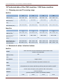
Assembly Instruction for CNC base machinery (partly completed machinery) Operating Instruction for CNC machinery (complete machinery) Type MiniFlat ModuFlat i-dimod GmbH Model MiniFlat P20, 40, 80, 100 ModuFlat P30, 60,70, 120 Im Leibolzgraben 16 D-36132 Eiterfeld Tel.: (06672) 898-800 Fax: -688 CNC base machinery / CNC machinery: MiniFlat, ModuFlat About this manual Used shortcuts MD Machinery directive 2006/42/EC Used symbols You will find different symbols in this manual that signalizes important information/ facts and danger. Warning! This symbol indicates dangers that cause damages for person’s health, physical injury or death. Warning! Dangerous voltage! Warning of danger from electricity. Ignoring can lead to serious injury or death. Attention! This Symbol indicates important notes. Ignoring this symbol leads to damages and malfunctions of the machinery Information: This symbol indicates important information and notes. Observe the safety instructions Before you take the CNC machine / CNC base machine MiniFlat or ModuFlat in operation, working with the machine or make additions or changes to the wiring of the machine / in the housing of the machine, make sure to read carefully the safety instructions in this manual. (Chapter Fehler! Verweisquelle konnte nicht gefunden erden.). Page 1 CNC base machinery / CNC machinery: MiniFlat, ModuFlat © i-dimod GmbH, 2010 All rights reserved. Despite all care, printing errors and mistakes For suggestions and information on errors, we are grateful. cannot be excluded. CE mark for (completed) CNC machinery: i-dimod CNC machinery are CE compliant and marked accordingly. For these machines is the CE declaration of conformity valid. No CE mark for partly completed machinery: Partly completed machinery (definition from EC machinery directive 2006/42/EC) has no CE mark. For partly completed machinery the declaration of incorporation (referred to in Annex II, part 1, section B) is valid. For all other machinery parts and components, be applied to the CE safety directives, initial operation are prohibited until all appropriate requirements are met. The company i-dimod GmbH assumes no responsibility or liability if you make any changes without the consent of the manufacturer of the machine that affect the CEconformity of the machine. The EMC test is valid only for the controller’s original configuration ex works, i.e. the delivery state. Manufacturer: i-dimod GmbH Im Leibolzgraben 16 D-36132 Eiterfeld Phone: (06672) 898-800 Fax: (06672) 898-688 E-Mail: [email protected] http://www.i-dimod.com Item-no.: 970280 BE015 (translation of operation instruction in German language) State: 06/2010 Technical changes reserved. Latest operating instructions and manuals for download, visit: www.isel-data.de/manuals Page 2 CNC base machinery / CNC machinery: MiniFlat, ModuFlat Table of contents 1 Introduction ............................................................................................................ 5 2 Intended use and reasonably foreseeable misuse ............................................. 7 3 Safety instructions ................................................................................................ 9 4 Scope of delivery / distribution state ................................................................. 11 Standard delivery ........................................................................................11 4.1 5 4.1.1 MiniFlat 11 4.1.2 ModuFlat 12 Installation and connection of the CNC machine ............................................. 13 5.1 Space requirements ....................................................................................13 5.2 Transport of the CNC machine ....................................................................14 5.3 Installation of the CNC machine ..................................................................15 5.4 Enclosure ....................................................................................................16 6 5.4.1 Enclosure with safety interlock on CNC machinery 16 5.4.2 Mounting of suitable protection measures at CNC base machinery 16 Initial operation .................................................................................................... 17 Preliminary ..................................................................................................17 6.1 6.1.1 Coordinate system and work piece zero point 17 6.1.2 Assignmet of the motion axles 17 6.1.3 Reference point, machine zero 18 6.1.4 Work piece clamping 18 Connections on the underside of the controller case...................................19 6.2 6.2.1 Connection of the standard version 20 6.2.2 Optional connections for components 24 6.3 Operation modes .........................................................................................26 6.4 Door lock .....................................................................................................28 6.5 Operation elements .....................................................................................29 6.6 Installing the CNC operation software .........................................................31 7 Accessories ......................................................................................................... 32 Page 3 CNC base machinery / CNC machinery: MiniFlat, ModuFlat 8 Cleaning, lubrication and maintenance ............................................................. 33 8.1 Cleaning ......................................................................................................33 8.2 Lubrication / maintenance ...........................................................................33 9 8.2.1 Basic lubrication 33 8.2.2 Later lubrication 33 8.2.3 Lubrication of the X axis 34 8.2.4 Lubrication of the Y axis 35 8.2.5 Lubrication of the Z axis 35 Faults .................................................................................................................... 36 10 Technical data of the CNC machine / CNC base machine ............................. 37 10.1 Clamping area and Traversing range ..........................................................37 10.2 Mechanical values / electrical values ..........................................................37 10.3 Sound pressure level...................................................................................38 11 Declaration of Conformity or Declaration of Incorporation?......................... 39 11.1 Declaration of conformity for complete machinery ......................................40 11.2 Declaration of incorporation for (partly completed) base machinery............41 12 Bibliography ...................................................................................................... 42 13 Index ................................................................................................................... 43 Page 4 CNC base machinery / CNC machinery: MiniFlat, ModuFlat 1 Introduction All i-dimod CNC base machinery (corresponding MD 2006/42/EC partly completed machinery) respectively i-dimod CNC machinery (corresponding MD 2006/42/EC complete machinery) of type MiniFlat or ModuFlat are proven CNC machinery. They provide the user a wide range of possibilities for 2D or 3D processing of work pieces. The machinery are constructed in different sizes and accomplishments. The base are exactly fitted and variable mountable standard profiles and drive units. Depending from the machinery demands according kinematics the units are mounted. The appearance of machine of one type is always the same. Applications of a concrete machine respectively the tool mounted on the Z axis are variously. All CNC base machinery / CNC machinery of type MiniFlat and ModuFlat have a unique control and safety concept as well as a unique design of the mechanics. Each single machine becomes configured, measured and tested for many hours before delivery to the customer. As presupposition for your work you need basic knowledge in CNC technique and PC application. It would be good to know also the terminology of the current valid MD: - MD 98/37/EU applicable until 28.12.2009 - MD 2006/42/EU from 29.12.2009 obligingly by law Please note this manual that you • install and do commissioning of CNC base machine / CNC machine correctly • can work safety, fast and effectively • keep away danger from persons and the equipment • can fully profit from the capabilities of CNC base machine / CNC machine The statements in this manual orientate to a standard complexity of deliver the CNC machine is ready for operation. Notes not related to the machine (e.g. accessory or software) you can skip when reading the manual the first time. The statements in this manual are basing on the following configuration / technical state of the CNC machine control system: Operator software is: ProNC /6/ or / Remote /7/ higher then version 1.45.6.0 For installation and commissioning the software or accessory, please note the supplemental manuals. They are composed in the source index of this manual. Page 5 CNC base machinery / CNC machinery: MiniFlat, ModuFlat Example CNC base machine MiniFlat 40, ModuFlat 60 partly completed machine equipped without tool, no clearly definition of application purpose with / without hood/safety door this CNC base machine is delivered without CE mark for this CNC base machine the Declaration of Incorporation is valid Example CNC machine MiniFlat 40, ModuFlat 60 complete machine equipped with tool milling spindle, so applicable for milling or drilling hood/safety door this CNC machine is delivered with CE mark for this CNC machine the Declaration of Conformity is valid Page 6 CNC base machinery / CNC machinery: MiniFlat, ModuFlat 2 Intended use and reasonably foreseeable misuse i-dimod CNC machinery / i-dimod CNC base machinery of type MiniFlat or ModuFlat are CNC controlled machinery with more than one linear axis resp. one or two optional rotation axis. The motor power amplifiers will be driven via a PC based stepper-motor-control. All control and power electronics for the axis is mounted in a control cabinet. Differences between CNC machine and CNC base machine: i-dimod CNC machine: In the new, at 29.12.2009 legally binding machine directive 2006/42/EC, is the term “machinery” defined as follows (quote from EC directive, article 2, letter a): „machinery“ an assembly, fitted with or intended to be fitted with a drive system other than directly applied human or animal effort, consisting of linked parts or components, at least one of which moves, and which are joined together for a specific application. Each i-dimod-CNC-machine delivered with a tool (e.g. milling or engraving spindle, metering device, measuring device like CCD camera or triangulation laser, water jet nozzle, plasma burner), is for the purpose of the directive 2006/42/EC a machine, because she was manufactured for a specific purpose resp. specific application and therewith a specific usage. The usage results from the kind of tool which is mounted on a moveable axis, e.g.: tool = milling tool tool = engraving tool tool = metering device tool = water jet nozzle usage for milling, drilling usage for engraving usage for metering usage for water jet cutting The manufacturer i-dimod GmbH is able to effect a legal prescribed risk assessment for the CNC-machines. CNC-machines will be delivered with a machinery enclosure. i-dimod CNC base machine: In the new, at 29.12.2009 legally binding machine directive 2006/42/EC is the term “partly completed machinery” defined as follows (quote from EC directive, article 2, letter g): „partly completed machinery” An assembly which is almost machinery but which cannot in itself perform a specific application. A drive system is partly completed machinery. Partly completed machinery is only intended to be incorporated into or assembled with other machinery or other partly completed machinery or equipment, thereby forming machinery to which this Directive applies; Each i-dimod-CNC-base-machine delivered without a tool and therefore not for a specific application is for the purpose of the directive 2006/42/EC a partly completed machine. The CNC-machine / CNC-base-machine is used for work in dry rooms (workshops, laboratories) and industrial firms (max. ambient temperature: 40°C) Page 7 CNC base machinery / CNC machinery: MiniFlat, ModuFlat CNC-machine: o The CNC-machine (complete machine) is according to the type mounted on the machine tool appropriately used. That is, the concrete tool of the CNC machine specifies the intended use of the machine within the meaning of the Machinery Directive (Annex I, Section 1.1.2). Under this premise, the CNC-machine is suitable for milling, drilling, cutting, engraving, metering, measuring or water jet cutting. The CNC-machine is not suitable for graphite machining. o Appropriate processing materials are light metals, plastics, wood, glass, platinum materials, etc. o Not permitted are materials which produces during processing harmful gases o The CNC-machine is prepared for an extraction unit device. This extraction unit is preferably suitable for dry dust (wood dust, fibreglass / fibreglass dust, platinum dust, etc.). The CNC base machine (partly completed machine) can be added by you as the buyer of the base-machine with a variety of appropriate processing tools to a CNC-machine (complete machine) in compliance with the requirements of the machinery directive. You are responsible for CE certification if you use the machine itself resp. sell (bring to market). The CE certification also includes the legally required identification of a safe machine by the CE mark. CNC-machinery for milling processes: o The CNC-milling-machines are designed for milling/drilling of the following materials: aluminium, copper, brass, plastics (e.g. GRP / fibreglass), wood o The processing of magnesium is prohibited because of fire. o During the processing of steel / stainless steel only engraving or a processing with low cutting forces is possible. o It shall not be used milling spindles with a tool holder greater than ISO 25 or HSK 25 (hollow shank taper). The speed of the spindle drive may not be higher than the corresponding processing speed for the material. o All machines are designed for milling spindles (spindle machining, induction motor) with a maximum of 3 kW drive power. o Cutters and drills may be used up to a maximum shaft diameter of 12 mm. o The tools form cutters and conical formers for timber industry may be used up to a maximum cutting diameter of 45mm and a shaft diameter of 12 mm. The rapid traverse velocity should not exceed the values of 150mm/sec till 200mm/sec depending on the machine size. The feed rate of the processing tool in the material must be determined technologically and should be smaller than the rapid traverse speed. For the secure clamping of the tools in the tool holder, the user is responsible. To the reasonably foreseeable misuse belongs the operation of the machine by two persons. It is prohibited that one person executes a motion of the axis of the CNC machine via software (manual move or program start) or by pressing the START button on the operating console / CNC operation panel and another person is touching into the machines workspace or do work in another way when the safety door is open and an axis movement is going on. You are not allowed to manipulate the locking of the safety door. Page 8 CNC base machinery / CNC machinery: MiniFlat, ModuFlat 3 Safety instructions Do not operate the machine in a potentially explosive atmosphere The machine is fully enclosed. The transparent panes (material: polycarbonate) mounted in the machine frame resp. in the door ensure during operation of the machine (setup or working process) protection against moving machine parts as well as eventually thrown work piece fragments from the work area. The housing protects you from moving tools, reduces the noise level and holds back chips. The door is locked during operation and cannot be opened (safety solenoid interlock). Please do not change or remove this mechanism. You are not allowed to put a CE marked CNC machine into operation if the enclosure is not complete, intact or the polycarbonate panes are damaged. The delivered CNC base machinery without safety door / hood are partly completed machinery for the purpose of the directive 2006/42/EC. They are delivered without a CE marking. It applies the declaration of incorporation and the assembly instruction. As the operator of the CNC base machine, you are responsible for taking appropriate protective measures based on your risk assessment to comply the requirements for the machine according to Machinery Directive 2006/42/EC. During operation of the CNC machine, we recommend the wearing of appropriate hearing protection and appropriate protective equipment (e.g. protective glasses) Be careful that work pieces are tightly clamped. The use of save and suitable parts / devices for work piece clamping is one of the tasks of the operator of the CNC machine. Unsuitable not safe devices for work piece clamping can cause unfasten of work piece from device during operation. This can result in heavy damage and accidents with fatality or personal damages. In this case can also damages of tool, work piece, clamping device or other parts of the machine occur. In case of emergency, you will find an emergency HALT switch on your hand control unit / CNC control panel. It will interrupt power supply for the power electronics (motor power amplifiers) and frequency inverter for main spindle drive (STOP category 0 – interrupt of drives power supply) The key switch on the hand control unit may be used only by knowledgeable and instructed persons, because in TEST mode there is an increased risk of damage. Page 9 CNC base machinery / CNC machinery: MiniFlat, ModuFlat Please keep the replacement key switch under your personal check. The operator has guarantee sufficient ventilation according accruement of dust or gas, caused by the operation process of working pieces. If the sound pressure level near the machine should be higher than 70 dB(A) the operator has to wear an applicative ear protection. The work at and with the machine is only allowed for authorized, knowledgeable and instructed persons. Those persons have to be informed by a special instruction about possibly appearing endangerments (especially residual risk). Do not use running water for cooling but a spray-cooling system with a spray-fog causing the cooling effect (look accessories). Drop formation and their gathering below the mounting table must be avoided. Page 10 CNC base machinery / CNC machinery: MiniFlat, ModuFlat 4 Scope of delivery / distribution state 4.1 Standard delivery 4.1.1 MiniFlat Models Item-No. 281110 0101 281110 1101 281111 0101 281111 1101 281110 0102 281110 1102 281111 0102 281111 1102 281110 0103 281110 1103 281111 0103 281111 1103 281110 0104 281110 1104 281111 0104 281111 1104 model MiniFlat 20 as desktop version without protection hood MiniFlat 20 as desktop version with protection hood MiniFlat 20 with under frame and without protection hood MiniFlat 20 with under frame and with protection hood MiniFlat 40 as desktop version without protection hood MiniFlat 40 as desktop version with protection hood MiniFlat 40 with under frame and without protection hood MiniFlat 40 with under frame and with protection hood MiniFlat 80 as desktop version without protection hood MiniFlat 80 as desktop version with protection hood MiniFlat 80 with under frame and without protection hood MiniFlat 80 with under frame and with protection hood MiniFlat 100 as desktop version without protection hood MiniFlat 100 as desktop version with protection hood MiniFlat 100 with under frame and without protection hood MiniFlat 100 with under frame and with protection hood Standard version - CNC base machine MiniFlat as desktop version without protection hood - Drive axles with ball screw spindle 16 x 5mm, 2,5mm inclusive end switches - Controller case inclusive: o Net input filter with main switch and fuses o 2-phase stepper motor power amplifiers up to 4 axles with max. 4,5 A rated current o Connector board with processor (core module) o Security circuit module o Power supply unit 48V and 24V o Hand control unit with function keys and emergency stop switch o net main cable o communication cable - control software Remote (version 1.46.2.1 or higher) - operating instruction / assembly instruction Options - protection hood with solenoid interlock - under frame - compressed air connection with maintenance unit and solenoid valves - frequency inverter max. 1,5KW - variable speed milling spindle - integrated control PC iPC10 - CNC control panel 10“ Page 11 CNC base machinery / CNC machinery: MiniFlat, ModuFlat 4.1.2 ModuFlat Models Item-No. model 275409 55665 275400 55665 275408 55665 275407 55665 275419 55665 275410 55665 275418 55665 275417 55665 275429 55665 275420 55665 275428 55665 275427 55665 275439 55665 275430 55665 275438 55665 275437 55665 ModuFlat 30 as desktop version without protection hood ModuFlat 30 as desktop version with protection hood ModuFlat 30 with under frame and without protection hood ModuFlat 30 with under frame and with protection hood ModuFlat 60 as desktop version without protection hood ModuFlat 60 as desktop version with protection hood ModuFlat 60 with under frame and without protection hood ModuFlat 60 with under frame and with protection hood ModuFlat 70 as desktop version without protection hood ModuFlat 70 as desktop version with protection hood ModuFlat 70 with under frame and without protection hood ModuFlat 70 with under frame and with protection hood ModuFlat 1200 as desktop version without protection hood ModuFlat 120 as desktop version with protection hood ModuFlat 120 with under frame and without protection hood ModuFlat 120 with under frame and with protection hood Standard version - CNC base machine ModuFlat as desktop version without protection hood - Drive axles with ball screw spindle 16 x 5mm, 2,5mm inclusive end switches - Controller case inclusive: o Net input filter with main switch and fuses o 2-phase stepper motor power amplifiers up to 4 axles with max. 4,5 A rated current o Connector board with processor (core module) o Security circuit module o Power supply unit 48V and 24V o Hand control unit with function keys and emergency stop switch o net main cable o communication cable - control software Remote (version 1.46.2.1 or higher) - operating instruction / assembly instruction Options - protection hood with solenoid interlock - under frame - compressed air connection with maintenance unit and solenoid valves - frequency inverter max. 1,5KW - variable speed milling spindle - integrated control PC iPC10 - CNC control panel 10“ Page 12 CNC base machinery / CNC machinery: MiniFlat, ModuFlat 5 Installation and connection of the CNC machine 5.1 Space requirements Page 13 CNC base machinery / CNC machinery: MiniFlat, ModuFlat The required space for the machine is limited to the outer dimensions of the machine, the controller case and the optional CNC control panel as well as enough space in front or side of the machine to operate it and to be able to set up. The door of the machine hood opens upward so you need additional space above the machine (see also chapter 10). When planning the floor space for the CNC machine regard the universal access for instructed personnel during a maintenance resp. service phase! 5.2 Transport of the CNC machine Remove the transport lock from the frame feeds. Use only appropriate lifting equipment (fork lift, trucks, see picture). Lift the machine only from below and do not pull up on the cover. In case of a later transfer, please make sure that the net and connection cables are not damaged. Unplug the power supply cable before each transport Take care during transport that the machine is not suspended to heavy vibrations. Keep the triangular wrench for manual unlock of the door outside the machine. Page 14 CNC base machinery / CNC machinery: MiniFlat, ModuFlat 5.3 Installation of the CNC machine The clamping / processing area of the CNC machine and all axes are aligned precisely at right angles from the factory. Never loosen the fastenings of the axles or the mounting bracket, in which the transverse axis (X-fitted axis). Otherwise, the machine must be re-measured by a technician from manufacturer i-dimod GmbH. Place the machine on a plane and solid area. You can compensate the unevenness of the floor / table with the adjustable feet. For precise alignment of the machine you need a spirit level with an accuracy of at least 0.1 mm/m. Save the height of the machine feet with the lock nut. Page 15 CNC base machinery / CNC machinery: MiniFlat, ModuFlat 5.4 Enclosure 5.4.1 Enclosure with safety interlock on CNC machinery The transparent panes (material: polycarbonate) mounted in the machine frame resp. in the door ensure during operation of the machine (setup or working process) protection against moving machine parts as well as eventually thrown work piece fragments from the work area. You are not allowed to put a CNC marked CNC machine into operation if the enclosure is not complete, intact or the polycarbonate panes ore damaged. 5.4.2 Mounting of suitable protection measures at CNC base machinery The delivered CNC base machinery without safety door / hood resp. without in the machine frame fixed transparent panes are partly completed machinery for the purpose of the directive 2006/42/EC. They are delivered without a CE marking. It applies the declaration of incorporation and the assembly instruction. You are not allowed to put the delivered CNC base machine into operation if you have not mounted appropriate protective measures. As the operator of the CNC base machine, you are responsible for taking appropriate protective measures based on your risk assessment to comply the requirements for the machine according to Machinery Directive 2006/42/EC. Page 16 CNC base machinery / CNC machinery: MiniFlat, ModuFlat 6 Initial operation 6.1 Preliminary 6.1.1 Coordinate system and work piece zero point The coordinate system of the CNC machine is set as a right system as shown in the picture. The work piece zero point P0 be defined by the software (e.g. via teach in) or is freely programmed in the user program. Yellow labels on the axes marks both the axes (X, Y or Z as axis letter for linear axes, A, B or C as letter for rotation axis) as well as the positive / negative axis direction of linear axis resp. positive / negative rotation direction or rotation axis. If you need to change the arrangement of the coordinates, please read the instruction manual of the control software Remote /6/. For questions, please contact our technical support. 6.1.2 Assignmet of the motion axles The assignment of the axles depending by the user position is: On flatbed machinery: X-axis = transverse axis (+X right; -X left) Y-axis = longitudinal axis (+Y away from the operator; -Y to the operator) Z-axis = lift axis (+Z up; -Z down) On the flatbed machinery (e,g. MiniFlat, ModuFlat) the work piece clamping area is mounted on the machinery frame. The work piece is not moved. A Y-axis movement of the tool (i.e. work tool tip) in positive direction (Y+) is away from the user position. Page 17 CNC base machinery / CNC machinery: MiniFlat, ModuFlat 6.1.3 Reference point, machine zero The reference point of the machine (machine zero) and home position are ex factory at the following axis position: At the back (Y-axis) left (X-axis) at the top (Z-axis) The reference point is set by the hardware limit switches (factory set). The axis direction is always considering by the tool tip therewith the coordinate system is a right system (right hand regular). 6.1.4 Work piece clamping When you set up your machine you have to use only suitable and safe clamping tools (see also chapter accessories). Note that the work pieces are always solid fixed. Page 18 CNC base machinery / CNC machinery: MiniFlat, ModuFlat 6.2 Connections on the underside of the controller case optional connections standard connections Page 19 CNC base machinery / CNC machinery: MiniFlat, ModuFlat 6.2.1 Connection of the standard version ➀ RS485 (Bus) – bus connector (in preparation) Not used in this version of the controller! ➁ RS232 (PC) - programming interface, Sub-D9-pin plug Communication between stepper motor control and control PC is realized via a serial interface (RS232). Use the delivered communication (null modem) cable for connection. A software protocol realizes the faultless transmission of the ASCII characters. Therefore it’s necessary that both systems respect the communication protocol: The connected control PC sends a command which ends with a line end character [CR, char (13)]. The processor unit quits the execution or storing of a command with the quitting signal 0[char (48)] or returns an occurred error with an ASCII character unequal 0. Data transfer parameters: - 19200 baud - 8 data bits - 1 stop bit - no parity ➂ Analog - Out, Sub-D9-pin female Use this connector to drive an external frequency inverter with the corresponding working spindle via a 0 – 10 V analog output. pin 1 2 3 4 5 6 7 8 9 description +24VDC n.u. n.u. make contact 1(potential free contact) analog 0 ...10V GND n.u. make contact 1(potential free contact) GND Page 20 CNC base machinery / CNC machinery: MiniFlat, ModuFlat ➃ Cover - Sub-D9-pin female This connector is used to integrate a door lock switch to the security circuit of the controller. pin description 1 2 3 4 5 6 7-9 + coil break contact switch 1.1 (bridge to pin 3 if no safety door is used) switch 1.2 (bridge to pin 2 if no safety door is used switch 2.1 (bridge to pin 5 if no safety door is used switch 2.2 (bridge to pin 4 if no safety door is used - coil break contact n.u. If no cover or safety door / hood is used the pins 2, 3 and 4, 5 must be bridged. Therefore use the enclosed Sub-D 9-pin plug. ➄ Remote - security circuit interface, 8-pin female Use this connector to include the controller into a higher ranked security circuit system. Please note that the external power input is only useable if the power button from the controller front is switched off. That will be realized by bridging the pins 1 and 2. pin 1 2 3 4 5 6 7 8 description power button select power button select external power (make contact) external power (make contact) external emergency stop channel 1 (brake contact, 11) external emergency stop channel 1 (brake contact, 12) external emergency stop channel 2 (brake contact, 21) external emergency stop channel 2 (brake contact, 22) Use external emergency stop: pin 5 and 6 bridged pin 7 and 8 bridged The length of the connection cable for the external emergency stop button must not more than 5m. Use external power button: pin 1 and 2 bridged connect external power button (make contact) on pin 3 and 4 Page 21 CNC base machinery / CNC machinery: MiniFlat, ModuFlat ➅ Output - digital outputs, 8-pin female The controller has 8 digital user outputs. Use these outputs to connect external devices like relays, or inputs from other devices. The maximum load of each relay output is 24 VDC/300 mA. Do not short 24VDC reference potential of the controller with GND or case ground. If you have pushed the emergency stop switch all states of the binary user outputs will be maintained and not reset! The binary user outputs 1 – 8 (left to right) must be wired as shown opposite. The transistor outputs (output 1 – 8) can be rated with 300 mA per output. If all outputs are switched (1-active) the maximum load of the internal 24VDC power supply unit is 1, 5 A (ca. 180mA per output). ➆ Input - digital inputs, 8-pin female The controller has 8 digital user inputs. Use these inputs to connect external devices like sensors, switches or outputs from other devices. All inputs are optodecoupled. If +24VDC lies on the input a logical HIGH is signalized. Not connected (e.g. switch open) a logical LOW is signalized. Do not short 24VDC reference potential of the controller with GND or case ground. The binary user inputs 1-8 (left to right) must be wired as shown opposite. The load of the controller internal 24V power supply unit amounts on 1-active state 4 mA per input. Page 22 CNC base machinery / CNC machinery: MiniFlat, ModuFlat ➇ Impulse - interface impulse control, 8-pin female Use this connector to integrate the function keys start button, stop button and reset from the controller front side as external signal inputs. pin 1 2 3 4 5 6 7 8 description input external START button +24VDC input external STOP button output lamp START button GND output lamp STOP button input length measure switch +24VDC If the external STOP button is not used pins 2 and 3 must be bridged. ➈ GND - GND connection of the 24V DC, 8-pin female ➉ +24V - +24V DC, 8-pin female ⑪ Stepper-Motor - motor axis X-, Y-, Z-, A, Sub-D9-pin socket SubD-9-pin connector for motor modules (CNC axis) Connect / disconnect the Sub-D plug only if the controller is switched off. Ignoring this instruction can lead to damage the motor cable or stepper motor amplifier. pin 1 2 3 4 5 6 7 8 9 description motor phase 2B motor phase 2A motor phase 1B motor phase 1A +24VDC brake (+24VDC/1,8A output with reference potential GND) limit switch 2 (Input +24VDC, if limit switch 2 is not actuated: NC GND limit switch 1 (Input +24VDC, if limit switch 1 is not actuated: NC The connection of a stepper motor with brake is only on the connector of the Z-axis possible. At this jack the switching signal (+24 V to pin 6) for the motor brake is provided. Page 23 CNC base machinery / CNC machinery: MiniFlat, ModuFlat ⑫ Working spindle – 115/230V output, 3-poles Use this output connector to directly tap a working spindle without speed control. Use the delivered mating connector. Maximum load of the relay output is 230 V AC / 6A. ⑬ Control elements - Sub-D25-pin plug On this connector you can plug the control elements (button, switches) from - an external control console (standard version) - the front-side of the machine - the mounted CNC control panel (CNC - control panel 10”) with the corresponding signal connector of the security circuit module inside the controller case. ⑭AC-Input - net input module 230 VAC, 60 Hz The net input module consists of net input socket, net filter, fuse holder and net main switch. Connect the controller via delivered net cable to a free receptacle. After that you can switch on the controller with the net main switch. 6.2.2 Optional connections for components ⑮ iPC 10 – connection for control computer iPC10, 8-pin female The control computer iPC10 is used instead of an external PC/notebook. Operating units, such as mouse, keyboard and monitor can be plugged to the corresponding connectors. The existing serial port (RS232, COM) is used for communication with the machine control in CNC and DNC mode. Detailed information can be found in the user manual of the iPC series /3/. Using the iPC10 with a isel CNC control panel To use the iPC10 with a CNC control panel (see also /4/ CNC control panel operating instruction) you have to connect the 8-pin connector of the CNC control panel to the 8-pin socket ⑯. The wires on the plug connecting the power button on the right side of the CNC control panel, the LEDs on the front panel and the power supply for the LC display with the appropriate connectors on iPC10. Switch the iPC10 on by shortly pressing the button on the right side of the CNC control panel. The power LED (green) on the CNC control panel should now shine. Page 24 CNC base machinery / CNC machinery: MiniFlat, ModuFlat ⑯ Connection for CNC control panel -8-pin female To use the iPC10 with a CNC control panel (see also /4/ CNC control panel operating instruction) you have to connect the 8-pin connector of the CNC control panel to the 8-pin socket ⑯. The wires on the plug connecting the power button on the right side of the CNC control panel, the LEDs on the front panel and the power supply for the LC display with the appropriate connectors on iPC10. Switch the iPC10 on by shortly pressing the button on the right side of the CNC control panel. The power LED (green) on the CNC control panel should now shine. pin (left to right) 1 2 3 4 5 6 7 8 function PWR BTN + PWR BTN GND PWR LED GND PWR LED +5VDC HDD LED GND HDD LED +5VDC +12VDC GND description power button + power button GND Power status LED GND power status LED + HDD activity LED GND HDD activity LED + power supply for LC display +12V power supply for LC display GND ⑰Main spindle drive connector Use this connector to tap speed controlled working spindle (asynchronous motor, e.g. iSA500). The (optional) frequency inverter is mounted inside the controller and will be controlled over the security-circuit- and I/O-module. Only machinery models with frequency inverters! ⑱ Compressed air outlet from solenoid valves Depending on the installed components (e.g. vacuum table, cool spray device) can be integrated here for up to five solenoid valves in the controller case. Note the air pressure values for the respective components in chapter 7 Accessories. ⑲ Compressed air supply valve with integrated maintenance unit Compressed air supply from compressor. Page 25 CNC base machinery / CNC machinery: MiniFlat, ModuFlat 6.3 Operation modes The processors operating system (firmware processor core) provides the following operation modes: DNC-mode of the control: Computer/Laptop is permanent connected to the stepper motor controller via serial interface Software Remote(optional: ProNC, Galaad) is used to operate the controller CNC-mode of the control: The stepper motor controller executes user programs stand alone without a connected PC/Laptop Software PALPC 2.1 is used for programming and download of user programs into the flash memory of the controller In DNC mode the stepper motor controller of the machine is connected permanently via RS-232 interface with a control computer (IBM compatible PC or Notebook). A user program stored in flash memory will not be executed. The commands to execute an action/motion (e.g. reference motion, motion of the axis or I/O actions) will be sent by user software from the computer with the new Remote (optional: ProNC, Galaad) motion control for 4-axis stepper motor controller (IMC4 compatibility mode). COM interface on computer: 9-pin Sub-D (plug) Serial cable Sub-D9-pin (socket socket) Page 26 CNC base machinery / CNC machinery: MiniFlat, ModuFlat The CNC mode (automatic mode = CNC mode) is the program controlled mode of the stepper motor control of the machine. That means that a user program which is saved in the controller’s memory (flash) will be executed till the end. During the automatic mode (CNC mode) you can stop the execution of the active user program by pressing the STOP-key on the hand control unit / CNC control panel or by using the external STOP input. A following operation of the START-key hand control unit / CNC control panel or the activation (1-active) of the external start input effects the resumption of the automatic mode. COM interface on computer: 9-pin Sub-D (plug) Serial cable Sub-D9-pin (socket socket) Page 27 CNC base machinery / CNC machinery: MiniFlat, ModuFlat 6.4 Door lock For special cases (e.g. door lock defect or loss of power supply voltage of the machine) you can use the triangular key (enclosure of the CNC machine) to open the door lock manual. Manual door unlock: 1. Switch off the machine. 2. Turn the triangular key – without using great force- a half turn to the left and open the door. The stepper motors of the machine are not powered. 3. Turn the triangular key back to the right. You may not operate the machine in this state. Page 28 CNC base machinery / CNC machinery: MiniFlat, ModuFlat 6.5 Operation elements The operation of the CNC machine takes place via the buttons on the external hand control unit or optionally via the buttons on the CNC control panel / 4 /. CNC control panel external hand control unit 1 - emergency stop switch Turns off the power supply for the motor power amplifiers and the working spindle in case of any danger. This means dangers for the user’s health or machine safety. The integrated security circuit is applicable till safety category 3 (DIN EN945-1). If you push the emergency stop switch the motor power supply will be switched off immediately (DIN EN 60204-1, stop category 0) and any axes motion will be stopped. The main power supply voltage of 115/230VAC lies still on the device, only the motor power supply voltage for the amplifiers is switched off. 2 - fault-lamp The fault lamp indicates an error within the safety circuit. 3 - POWER button Use this button to switch on motor power supply voltage for the motor power amplifiers. Conditions for switch on: - Main power switch on the controller back side is switched on - Emergency stop button is pulled out Page 29 CNC base machinery / CNC machinery: MiniFlat, ModuFlat Be sure that the contacts for external emergency stop switch on the remote connector are bridged! If power supply voltage is successfully switched on the power button is lighted green. 4 - start-button If you press the start button in CNC mode (see chapter 6.3 Operation modes) a saved user program in the flash memory will be executed. You cannot use the start switch in DNC mode. 5 - stop-button If you press the stop button in CNC mode an active user program / axis motion will be stopped. You can continue the execution of the user program by pressing the start button. If you press the stop button in DNC mode an active user program / axis motion will be stopped. To continue the execution of the user program you have to use the controller software (ProNC, Remote). 6 - cover-button Use this button to open the machines cover or safety door. This is possible only if the conditions from point “6 – operation mode switch“are complied. An enable for opening of the cover or safety door is signalized by a white lighted cover button. 7 - ACK (ACKnowledge-button) This button has no function on 4-axis-Controller iMC-M and iMC-MP. 8 - operation mode switch (key switch) Use this switch to choose between automatic- and setup-mode. In automatic-mode you can only open the cover or safety door of the machine if no axis is in motion and the mounted working spindle is switched off (means that spindle does not turn). In the setup-mode you can only open the cover or safety door of the machine if the mounted working spindle is switched off (means that spindle does not turn). You can just move the axes at opened cover or safety door if you press the ACK button. Ensure that in setup-mode (key switch on TEST) only authorized personal operates on the machine. Page 30 CNC base machinery / CNC machinery: MiniFlat, ModuFlat 6.6 Installing the CNC operation software The CNC software Remote supplied with your CNC machine is inclusive of the relevant manuals. Remote operation instruction /6/ The manuals are stored in PDF format on your installation medium. For installing Remote please read the operation instruction of the software Remote on chapter 2.8.3.1 „Configuration“/6/. More information on the CNC software, please see the appropriate manuals or the ReadMe files on the installation media. Alternatively you can start the installation assistant. This assistant will guide you through the setup process. Page 31 CNC base machinery / CNC machinery: MiniFlat, ModuFlat 7 Accessories Matching for each CNC machine, you can order the following accessories: clamping set (clamp lever SH1,SH2, 2 stop rails, hexagon socket wrench) additional mounting material for T-groove panel bench vise 1, 2 additional collet chucks for working spindle tool kit cutter, driller, graver three different tool changer (linear, direct or round changer) with high frequency main spindle drive, option: length measurement button rotation axis(axes) main spindle drive iSA 500, 750, 900 working spindle UFM 500, UFM 1050 vacuum clamping system isel-Vakufit pneumatics accessories cold air cooling isel-CoolMin: cooling unit with cold air nozzle (up to -20°C) exhaust unit industrial vacuum cleaner engraving spindle diamond engraving head spray-/cooling unit, cooling medium HL4 isel-special grease for central lubrication o fat cartridge: article number: 299032 0002 o greaser: article number: 299032 0003 CAD/CAM software isyCAD/CAM 2.5, Galaad/Lancelot, ProNC /6/ Information for compressed air connection of accessories: To use the optional vacuum clamping system or the tool changer and collets of the working spindle it’s necessary that the location of the machine has a compressed air connection. accessories air pressure air consumption pneumatic vacuum pump 4 - 6 bar 100-150 l/min (1 nozzle) cold air nozzle 3 - 10 bar 100-150 l/min cover of the tool changer 3 - 6 bar impulse milling spindle with automatic tool change > 7.5 bar impulse 2 bar impulse on the milling spindle mounted swivel unit for exhaust (specially for woodworking) The necessary software for tool changing inclusive tool length measurement is a part of the control- and programming software Remote / ProNC. Look at all accessories for a professional installation and note the applicable standards and safety regulations. Page 32 CNC base machinery / CNC machinery: MiniFlat, ModuFlat 8 Cleaning, lubrication and maintenance Switch off the main switch before every cleaning or maintenance avoiding an accidental switching on. 8.1 Cleaning Clean the machine regularly with a hand brush or vacuum cleaner (no compressed air) from all chips. This protects the mechanics from premature wear. The seal lips include a Teflon component and require no special maintenance. Clean the polycarbonate panes with a not scouring plastic cleaner. 8.2 Lubrication / maintenance The guide rails and drive shafts are fitted from the factory with a long-term central lubrication. Depending on the strain, you should regrease the guides and drive shafts in an interval of about 500-1000 hours of operation. Please use the grease gun available as accessories for centralized and the associated specialty grease. If you use oil, please lubricate in an interval of about 100-200 hours of operation Lubricate not too much at once, the wave rails and steel rails must not swim in the grease 8.2.1 Basic lubrication The drive components are lubricated at the factory with isel special grease. You can immediately drive the axis. 8.2.2 Later lubrication For the lubrication of linear bearings with waves is only the isel special grease used. Under the following article numbers the grease can be ordered: 299032 0002 grease cartridge 299032 0003 grease gun Depending on the application is recommended that every 500 to 1000 operating hours you have to lubricate the axles. Unplug the power supply cable of the machine before each lubrication process. Page 33 CNC base machinery / CNC machinery: MiniFlat, ModuFlat grease properties: The isel special grease has the following properties: Enormously wear out reduction less grease consumption mixable with lithium and calcium greases water resistant highly resistant against cold- hot- and salt-water as well as solvent temperature range: –25°C till 200°C fail safe >300°C up to six fold service life extension extremely good adhesion to metal surfaces Classification and marking complies with the EC directives 67/548/ EC and 88/379/ EC – water hazard class 1. Before you start up lubrication of the axis 1.) Move the X-axis and Y-axis to the centre of the traversing area and the Z-Axis up to their reference position. 2.) Open the safety door / cover of the machine and switch off the main switch of the control. 3.) Unplug the power supply cable of the machine. 8.2.3 Lubrication of the X axis From the operator side you can see on the X-axis (transverse axis) two white plastic stoppers. Pull the stopper out and move the axis manually left or right until you can see the grease nipples. Lubricate the axis with the grease gun. Push the stopper back into their original position. MiniFlat/ModuFlat: grease nipples on the X axis Page 34 CNC base machinery / CNC machinery: MiniFlat, ModuFlat 8.2.4 Lubrication of the Y axis The grease nipples of the Y axis are located near the guiding rails of the axis. If not already done move the Y axis in the half of the possible traversing area. Start the lubrication of each single guiding rail from the bottom on the front and back side of the machine. To lubricate the ball screw you have to attach the grease gun from the rear right to the angled grease nipple. MiniFlat/ModuFlat: grease nipples on the Y axis 8.2.5 Lubrication of the Z axis On the Z axis (vertical mounted to the slide plate of the X axis) is on the lower side (bearing surface side relating to drive) a cover plate is mounted. Remove the fixing screws and the cover plate. Under the cover plate is located a grease nipple. Attach the grease gun on the grease nipple and lubricate your axis. If you have finished the lubrication, mount the cover plate again to the Z axis. MiniFlat/ModuFlat: grease nipples on the Z axis Page 35 CNC base machinery / CNC machinery: MiniFlat, ModuFlat 9 Faults Error machine will not turn on power supply voltage cannot switch on by POWER button software works not correctly no communication via serial interface milling spindle is not working moving distances of the axles is incorrect reason solution net input plug not connected check net input cable connection main switch not switched on switch on main switch fuse defect remove net input plug, renew fuse hood / door is not closed close hood / door Emergency stop switch is unlocked unlock Emergency stop switch main switch not switched on switch on main switch power supply for the power amplifiers not switched on power amplifiers by pressing POWER-button motor cables not connected check motor cables incorrect COM port selected select correct COM port incorrect baud rate select 19200 baud incorrect setting in the spindle module DLL (only DNC mode) switch on the milling spindle (only 115/230 V) is switched OFF spindle pitch is not correct in the software Remote (in DNC mode) spindle pitch is not correct set in the initialize section of user program or in the programming software PALPC (in CNC-mode) Page 36 check settings and change if applicable switch on change spindle pitch in software Remote/6/ change spindle pitch in the user program or programming software PALPC CNC base machinery / CNC machinery: MiniFlat, ModuFlat 10 Technical data of the CNC machine / CNC base machine 10.1 Clamping area and Traversing range MiniFlat Traversing range X/Y/Z in (mm) Table clamping area W x D in (mm) Opening (mm) Dimensions W x D x H in (mm) MiniFlat 20 MiniFlat 40 MiniFlat 80 MiniFlat 100 300 x 200 x 150 300 x 400 x 150 300 x 800 x 150 300 x 1000 x 150 325 x 600 325 x 800 325 x 1200 325 x 1400 200 750 x 630 x700 750 x 830 x 700 750 x 1230 x 700 750 x 1430 x 700 ModuFlat 30 ModuFlat 60 ModuFlat 70 ModuFlat 120 400 x 300 x 150 400 x 600 x 150 800 x 600 x 150 800 x 1200 x 150 550 x 750 550 x 1000 950 x 1000 950 x 1750 ModuFlat Traversing range X/Y/Z in (mm) Table clamping area W x D in (mm) Opening (mm) Dimensions W x D x H in (mm) without base frame with base frame 200 850 x 820 x730 850 x 820 x 1310 850 x 1070 x 730 850 x 1070 x 1310 1250 x 1070 x 730 1250 x 1820 x 730 1250 x 1070 x 1310 1250 x 1820 x 1310 10.2 Mechanical values / electrical values MiniFlat Guides linear units with precision steelshafts and ball circulation skid, clearance free adjustable Process speed X/Y/Z in (mm/s) Repeat accuracy (mm) 100 ≤ 0,02 Drive motors stepper motors Drive elements X/Y/Z Control ball screw assemblies adjustable backslash-free Step-Controller iMC-P with 4 motor power amplifiers 48V/4,5A and power supply unit 500W with CPU board, alternatively with step direction interface module operation function keys, Emergency OFF (optional: CNC control panel) Software PAL-PC, Remote (optional: Windows, ProNC, isyCAD/CAM, Galaad) Weight (kg) ca 60 ca 66 Page 37 ca 78 ca 84 CNC base machinery / CNC machinery: MiniFlat, ModuFlat Controller case with net input (1-phase): 100 - 230VAC, 50…60 Hz, L1/N/PE, Net fuses: 6,3A, slow Connection type: not fixed installation according to EN 60204-1, section 5.1 „net input connectors“ ModuFlat linear units with precision steelshafts and ball circulation skid, clearance free adjustable Guides Process speed X/Y/Z in (mm/s) Repeat accuracy (mm) 50/100 ≤ 0,02 Drive motors stepper motors Drive elements X/Y/Z ball screw assemblies adjustable backslash-free Step-Controller iMC-P with 4 motor power amplifiers 48V/4,5A and power supply unit 500W with CPU board, alternatively with step direction interface module Control operation function keys, Emergency OFF (optional: CNC control panel) Software PAL-PC, Remote (optional: Windows, ProNC, isyCAD/CAM, Galaad) Weight (kg) ca 60 ca 66 ca 78 ca 84 Controller case with net input (1-phase): 100 - 230VAC, 50…60 Hz, L1/N/PE, Net fuses: 6,3A, slow Connection type: not fixed installation according to EN 60204-1, section 5.1 „net input connectors“ 10.3 Sound pressure level The sound pressure level varies by application and toolkit. Sound pressure level without working spindle: < 75 dB (A) Technical changes reserved! Page 38 CNC base machinery / CNC machinery: MiniFlat, ModuFlat 11 Declaration of Conformity or Declaration of Incorporation? In the new, at 29.12.2009 legally binding machine directive 2006/42/EC, the term “machinery” is defined as follows (quote from EC directive, article 2, letter a): „machinery“ An assembly, fitted with or intended to be fitted with a drive system other than directly applied human or animal effort, consisting of linked parts or components, at least one of which moves, and which are joined together for a specific application. For each i-dimod CNC machine delivered with a tool (e.g. milling or engraving spindle, metering device, measuring device like CCD camera or triangulation laser, water jet nozzle, plasma burner) the Declaration of Conformity in this manual is valid. Those CNC machinery have to be used purposive for a specific application. This application results from the kind of tool mounted on a moveable axis: tool = milling tool tool = engraving tool tool = metering device tool = water jet nozzle usage for milling, drilling usage for engraving usage for metering usage for water jet cutting and so on. In the new, at 29.12.2009 legally binding machine directive 2006/42/EC, the term “partly completed machinery” is defined as follows (quote from EC directive, article 2, letter g): „partly completed machinery” An assembly which is almost machinery but which cannot in itself perform a specific application. A drive system is partly completed machinery. Partly completed machinery is only intended to be incorporated into or assembled with other machinery or other partly completed machinery or equipment, thereby forming machinery to which this Directive applies; For each i-dimod CNC base machine delivered without a tool (e.g. milling or engraving spindle, metering device, measuring device like CCD camera or triangulation laser, water jet nozzle, plasma burner) the Declaration of Incorporation in this manual is valid. These CNC base machinery have no purpose for a specific application. Page 39 CNC base machinery / CNC machinery: MiniFlat, ModuFlat 11.1 Declaration of conformity for complete machinery EC Declaration of Conformity corresponding Machinery Directive 2006/42/EU, Annex II A The manufacturer i-dimod GmbH Im Leibolzgraben 16 D- 36132 Eiterfeld declares hereby, that the following products Product designation: CNC machine MiniFlat / ModuFlat with safety hood and working tool Types: MiniFlat 20 Item-No.: 281110 1101, 281111 1101 MiniFlat 40 Item-No.: 281110 1102, 281111 1102 MiniFlat 80 Item-No.: 281110 1103, 281111 1103 MiniFlat 100 Item-No.: 281110 1104, 281111 1104 ModuFlat 30 Item-No.: 275400 55665, 275407 55665 ModuFlat 60 Item-No.: 275410 55665, 275417 55665 ModuFlat 70 Item-No.: 275420 55665, 275427 55665 ModuFlat 120 Item-No.: 275430 55665, 275437 55665 conforms to the safety and health requirements of the Machinery Directive 2006/42/EU, Annex I – including those at the time of declaration current alterations.. The following harmonized standards have been applied: EN ISO 12100-1:2003 EN ISO 12100-2:2003 EN ISO 13857:2008 EN 349:1993 EN 953:1997 EN 954-1:1996 Safety of machinery – fundamental terms, general principles of design – Part 1: Basic terminology, methodology Safety of machinery – fundamental terms, general principles of design – Part 2: Technical principles Safety of machinery – Safety distances to avoid reaching of dangerous regions with upper and lower extremities Safety of machinery – Minimum distances to avoid bruising of parts of the body Safety of machinery – Guards – general requirements for the design and construction of fixed and moveable guards Safety of machinery – Safety related parts of control systems, Part 1: General principles for design EN ISO 13850:2008 Safety of machinery – Emergency-Halt – Design guidelines EN 14121-1:2007 Safety of machinery – Risk assessment – Part 1: Guidelines EN 60204-1:2006 Safety of machinery – Electrical equipment of machines, Part 1: General requirements Also the following EU Directives have been applied EMC Directive 2004/108/EG Low Voltage Directive 2006/95/EG The technical documentation for this machine was created corresponding Annex VII Part A. The manufacturer obligates to provide the technical documentation in electronic mode on demand of authorized governmental agency. Representative for composition of technical documentation is: Herr Dieter Eckart Place: Eiterfeld Date: Hugo Isert, Manager Page 40 01.06.2010 CNC base machinery / CNC machinery: MiniFlat, ModuFlat 11.2 Declaration of incorporation for (partly completed) base machinery Declaration of Incorporation corresponding Machinery Directive 2006/42/EU, Annex II B The manufacturer i-dimod GmbH Im Leibolzgraben 16 D- 36132 Eiterfeld declares hereby, that the following products Product designation: CNC machine MiniFlat / ModuFlat without safety hood resp. with safety hood but without an working tool Types: MiniFlat 20 MiniFlat 40 MiniFlat 80 MiniFlat 100 ModuFlat 30 ModuFlat 60 ModuFlat 70 ModuFlat 120 Item-No.: 281110 0101, 281111 0101 Item-No.: 281110 0102, 281111 0102 Item-No.: 281110 0103, 281111 0103 Item-No.: 281110 0104, 281111 0104 Item-No.: 275409 55665, 275408 55665 Item-No.: 275419 55665, 275418 55665 Item-No.: 275429 55665, 275428 55665 Item-No.: 275439 55665, 275438 55665 conforms to the safety and health requirements of the Machinery Directive 2006/42/EU, Annex I – including those at the time of declaration current alterations. The following harmonized standards have been applied: EN 349:2008-09 EN ISO 12100-1:2003 EN ISO 12100-2:2003 Safety of machinery – Minimum distances to avoid bruising of parts of the body Safety of machinery – fundamental terms, general principles of design Part 1: Basic terminology, methodology Safety of machinery – fundamental terms, general principles of design Part 2: Technical principles EN ISO 13850:2008 Safety of machinery – Emergency-Halt – Design guidelines EN 14121-1:2007 Safety of machinery – Risk assessment – Part 1: Guidelines EN 60204-1:2006 Safety of machinery – Electrical equipment of machines, Part 1: General requirements Also the following EU Directives have been applied: EMC Directive 2004/108/EG Low Voltage Directive 2006/95/EG The technical documentation for this partly completed machine was created corresponding Annex VII Part B. The manufacturer obligates to provide the technical documentation in electronic mode on demand of authorized governmental agency. Representative for composition of technical documentation is: Mr. Dieter Eckart The product (partly completed machine) is provided for integration in a machine or to be bonded with other partly completed machine in sense with Machinery Directive 2006/42/EU, Article 1, Chapter (1), Character a. The partly completed machinery must not be put into service until the final machinery into which it is to be incorporated has been declared in conformity with the provisions of Machinery Directive 2006/42/EU. Place: Eiterfeld Date: Hugo Isert, Manager Page 41 01.06.2010 CNC base machinery / CNC machinery: MiniFlat, ModuFlat 12 Bibliography /1/ MD24 MD28 micro stepping driver: Instruction Manual / hardware description MD24 / MD28 ; isel Germany AG, 02/2009 /2/ Operating Instruction 4 axis stepper motor controller iMC-M / iMC-MP: Operating instruction 4 axis stepper motor controller iMC-M / iMC-MP; isel Germany AG, 08/2009 /3/ Operating instruction isel control computer iPC10: Operating instruction for control computer iPC10; isel Germany AG, 02/2009 /4/ Operating instruction for CNC-Bedienpanel: Operating instruction for CNC control panel iBP10 / iBP17; isel Germany AG, 07/2008 /6/ Remote: Operation and output program for ISO-, NCP- and CNC files: Software manual Remote; isel-automation 06/2005 /7.1/ EC machinery directive 98/37/EG /7.2/ EC machinery directive 2006/42/EG (till 28.12.2009 useable) (as from 29.12.2009 legally binding) Up to date Operating instructions and manuals for download you can find here: www.isel-data.de/manuals Page 42 CNC base machinery / CNC machinery: MiniFlat, ModuFlat 13 Index A accessories............................................................................................................................................................................................... 34 AC-Input .................................................................................................................................................................................................. 26 air pressure ............................................................................................................................................................................................. 34 analog output .......................................................................................................................................................................................... 22 B ball screw spindle .................................................................................................................................................................................... 11 C CE marking ........................................................................................................................................................................................... 9, 18 Circular form measuring system ............................................................................................................................................................. 13 Cleaning ................................................................................................................................................................................................... 35 CNC base machinery .................................................................................................................................................................................. 5 CNC control panel .................................................................................................................................................................................... 26 CNC software ........................................................................................................................................................................................... 33 CNC-mode ............................................................................................................................................................................................... 28 complete machinery ................................................................................................................................................................................. 5 control elements ..................................................................................................................................................................................... 26 Cover ....................................................................................................................................................................................................... 23 D Declaration of Conformity ...................................................................................................................................................................... 41 Declaration of Incorporation .................................................................................................................................................................. 41 digital inputs ............................................................................................................................................................................................ 24 digital outputs ......................................................................................................................................................................................... 24 DNC-mode ............................................................................................................................................................................................... 28 Door lock ................................................................................................................................................................................................. 30 door lock switch ...................................................................................................................................................................................... 23 E emergency HALT ........................................................................................................................................................................................ 9 Enclosure ................................................................................................................................................................................................. 18 external emergency stop ........................................................................................................................................................................ 23 external power button............................................................................................................................................................................ 23 F Faults ....................................................................................................................................................................................................... 38 flatbed machinery ................................................................................................................................................................................... 19 frequency inverter ................................................................................................................................................................................... 22 G GND ......................................................................................................................................................................................................... 25 grease ...................................................................................................................................................................................................... 34 Page 43 CNC base machinery / CNC machinery: MiniFlat, ModuFlat H Hand control unit..................................................................................................................................................................................... 11 I Initial operation ....................................................................................................................................................................................... 19 instructed persons ................................................................................................................................................................................... 10 interface impulse ..................................................................................................................................................................................... 25 iPC 10 ....................................................................................................................................................................................................... 26 iSA 34 isel-CoolMin ............................................................................................................................................................................................ 34 isel-Vakufit .............................................................................................................................................................................................. 34 K key switch ............................................................................................................................................................................................... 32 L laser interferometer ................................................................................................................................................................................ 14 lubrication ............................................................................................................................................................................................... 35 M machine zero ........................................................................................................................................................................................... 20 Main spindle drive .................................................................................................................................................................................. 27 MD 2006/42/EC ......................................................................................................................................................................................... 5 MiniFlat ................................................................................................................................................................................................... 11 ModuFlat ................................................................................................................................................................................................. 12 motor phase ............................................................................................................................................................................................ 25 O Operation elements................................................................................................................................................................................. 31 operation modes ..................................................................................................................................................................................... 28 Output ..................................................................................................................................................................................................... 24 P partly completed machinery .................................................................................................................................................................... 5 processing area ........................................................................................................................................................................................ 17 R reference point ....................................................................................................................................................................................... 20 Remote .................................................................................................................................................................................................... 11 Renishaw QC10 ........................................................................................................................................................................................ 13 RS232 ....................................................................................................................................................................................................... 22 Page 44 CNC base machinery / CNC machinery: MiniFlat, ModuFlat S safety door ................................................................................................................................................................................................ 8 safety interlock ........................................................................................................................................................................................ 18 serial interface ......................................................................................................................................................................................... 22 sound pressure level .......................................................................................................................................................................... 10, 40 Space requirements................................................................................................................................................................................. 15 specific usage ............................................................................................................................................................................................ 7 Standard delivery..................................................................................................................................................................................... 11 standard version ...................................................................................................................................................................................... 22 Stepper-Motor ........................................................................................................................................................................................ 25 suitable protection measures .................................................................................................................................................................. 18 T Technical data.......................................................................................................................................................................................... 39 Transport ................................................................................................................................................................................................. 16 triangular key .......................................................................................................................................................................................... 16 W work piece zero point ............................................................................................................................................................................. 19 Working spindle ...................................................................................................................................................................................... 26 Page 45