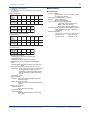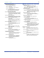
1
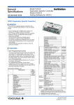
<<Contents>> <<Index>>
General
Specifications
DAQSTATION CX1000
Control and Measurement Station
GS 04L31A01-01E
■ OVERVIEW
CX1000 is a controller with up to 6 ch measurement
channels and up to 2 embedded loops. By using
Ethernet interface equipped as standard feature, it is
possible to send e-mails, monitor the site remotely on
the Web, and make an FTP-based file transfer.
CX1000 comes standard with control and measurement
screens; CX1000 operation screen can be used with
program-less. By using PV math/SP math or logic math
for each loop, CX1000 can be used for variety purposes.
■ DISPLAY SPECIFICATIONS
5.5-inch TFT color LCD (320 × 240
pixels)
Display color:
Selectable from 12 options for trend/
bar graphs
Background color: Selectable from white or black
Display unit:
Number of display channels/kinds (Max)
Input Type
● Display
Control Screen
Control group display
Number of loops covered: 4 max.
Number of displays: 4 (4 groups)
Display style: Controller, faceplate and hybrid style
DIO operation: Display on control screen
Setting DIO number: up to 12
Tuning display: Capable of assigning up to 21
parameters
Overview screen: Control loop up to 6 loops
Measurement ch: up to 6 ch
DIO status: up to 6
DI/DO status display: DI display number: up to 6
DO display number: up to 6
Program control display:
Simultaneously displays the program
operation status and current PV readings.
Number of loops covered: 2 Max.
Number of displays: 1 (1 group)
Display update interval:
Digital readings: 1 sec
Program readings: Same as the trend update interval
Program event display
Group display:
Up to 5 events and their names display
All display: All event display
All time events display:
All time events and the some events
names display
All PV events display:
All PV events and the some events
names display
Internal SW status screen: Display number: 18
Number of
Channels Covered
Internal loops
6
(Two loops x PV, SP and
OUT readings)
Green series communication
channels
12
(Four loops x PV, SP and
OUT readings)
Measurement channels
6
Computation channels (option)
12
Measurement Screen
Trend screen
Direction of view: Vertical or horizontal
Number of channels covered: 6 max./screen (group)
Number of trend views on all channels: 36 max.
Number of displays: 6 (6 groups)
Line width: Selectable from 1, 2 and 3 pixels
Screen update interval:
Selectable from 1 min, 2 min, 5 min, 10
min, 20 min, 30 min, 1 hr, 2 hr, 4 hr, and
10 hr/div
Bar graph display:
Direction of view: Vertical or horizontal
Number of channels covered:
6 channels max./display (group)
Number of displays: 6 (6 groups)
Scale: Configurable within a range from 4 to 12
Reference position = Edge or midpoint
Update interval: 1 sec
Digital display:
Number of channels covered:
6 channels max./display (group)
Number of displays: 6 (6 groups)
Update interval: 1 sec
GS 04L31A01-01E
©Copyright September, 2001
3rd Edition May, 2003
2
<<Contents>> <<Index>>
Overview display:
18 channels max. (including computation
channels) for measurement
Measured values and alarms for all channels.
Information display:
Jumps to the trend view of a data item
selected by the cursor.
Alarm summary display: Display the list of alarms.
Event summary display:
Display the list of events.
Control operation summary screen:
Display the list of control operation
statuses.
Message summary display:
Display the list of message and time.
Memory summary display:
Display the list of internal memory.
Tag display: Tag names for measurement channels (up
to 16 alphanumeric characters)
Tag names for control loops and DIO
(up to 8 alphanumeric characters)
Tag comments for control loops and DIO
(up to 8 alphanumeric characters)
Other on-display elements:
Memory status, scale values (0%, 100% can be turned on/off), scales (6 scales
max.), grid (selectable from a range of 4 to
12 divisions) with hour:min indications, date
and time (year/month/day and
hour:minute:second indications), trip line
(selectable from 1-, 2- and 3-pixel thickness
options), messages (of up to 16 characters
and 8 types), and alarm marks
Data reference function:
Display the retrieved data.
Display format: Bisectional or full-screen view
Time axis: Can be upscaled, downscaled, and
scrolled.
Automatic screen switching
Switching interval
5 sec, 10 sec, 20 sec, 30 sec, or 1 min
LCD back light saver function
Timer setpoint: 1, 2, 5, 10, 20 or 60 min
■ CONTROL FUNCTIONS
Control mode
Singleloop, cascade control, and loop control with PV
switching.
Control computation functions
Continuous PID control, Relay on/off control, time
proportional PID control
PID parameter: 8 sets/loop for each control mode
Points of zone PID switching: 6 max.
“Super” function (overshoot prevention)
Tracking functions: SP tracking PV tracking
Anti-reset windup function
(over-integration prevention function)
Control interval: 250, 500 or 1000 ms
All Rights Reserved. Copyright © 2001, Yokogawa Electric Corporation
Operation mode switching
• Switching among remote, local, and program modes
• Switching among manual, auto, and cascade modes
• Run/stop mode switching
Stop mode: Outputs the preset output value.
• Switching between Execute/Stop options of auto-tuning
Principle of auto-tuning: Limit cycle method
PID Control Method
PID
Control
mode
Operation
mode
Operating status
Standard Fixed point
PID control control
operation
mode
Local and cascade
control except cascade
secondary loop control
Remote or secondary
cascade loop control
Programmed
Local and cascade
control
control except
operation secondary cascade loop
control, hold or soak
During programmed
operation (without status
of hold or soak) or
secondary cascade loop
control
Fixed point Fixed point
Local and cascade
control
Control
control except cascade
operation
Mode
secondary loop control
Remote or cascade
secondary cascade loop
control
Programmed
Local, hold and soak
control
Programmed operation
operation
(without status of hold)
or secondary cascade
loop control
PID control
method
Bump of
control
output
PV derivative type
PID
Yes
Deviation derivative
type PID
PV derivative type
PID
Yes
Deviation derivative
type PID
Yes
PV derivative type PID
Yes
PV derivative type
PID
Yes
PV derivative type PID
PV derivative type
PID
No
Yes
Yes
*The secondary cascade loop is secondary loop of cascade control that is
selected from the cascade mode (auto, manual, cascade)
Setting ranges of control parameters
Proportional band: 0.1 to 999.9%
Integral time: 1 to 6000 sec, or off (for manual reset)
Derivative time: 1 to 6000 sec, or off
On-off control hysteresis wideth:
0.0 to 100.0% of measurement range
Preset output value: –5.0 to 105.0% of output
(Provided in case of control computation
being stopped, PV input being in a burnout
state, or instrument input being abnormal)
Output limiter:
Setting range: –5.0 to 105.0% for both high/low limits
Shutdown function:
Can provide a manipulated output of up to 0
mA when in manual mode operation with
4-20 mA output (shuts down the output for
values smaller than –5.1%).
Output rate-of-change limiter:
Off, or a value from 0.1 to 100.0%/sec
GS 04L31A01-01E
3rd Edition May.20,2003-00
3
<<Contents>> <<Index>>
● PV math/SP math function
Math expression can be assigned to PV and SP of each
loop
Type of computation:
Four arithmetic operations, square root,
absolute, common logarithm, exponential,
power, relational operations (, , , , , ),
logic operations (AND, OR, NOT, XOR),
Statistical operations (average, Max. Min. Max.Min.) conditional operations( [expression 1 ?
expression 2 ? expression 3 ])
Note: Conditional operators can be used with the other
operands together
Available operands for arithmetic operations:
Measurement data, measurement math
data, embedded/external control data,
communication input data, constant W01W12, control input data, control output DIO,
expansion module DIO, measurement
remote input, internal switch
Operation limitation: Within 120 characters
Available operands in an expression: less than 35
In error case: Over/Under selection
Over: Upper limit of PV/SP value
Under: Lower limit of PV/SP value
● Logic Math
Available number of operations: Up to 12
Operation type:
Relational operations (, , , , , ),
logic operations (AND, OR, NOT, XOR),
conditional operations( [expression 1 ?
expression 2 ? expression 3 ])
Note: Conditional operators can be used with the other
operands together
Available operands in an expression:
Same as PV math/SP math operands
● Internal SW
Number of available internal SW: 18
Non-hold type only
● Analog retransmission
Output type: Current output (4-20mA, 0-20mA, 20-4mA,
20-0mA), time proportional voltage pulse
output, time proportional relay output
Display/record: Data is recorded/displayed as out value
Note: The loop of analog retransmission mode can
calculate PID Math.
Available math operation: Same as PV math/SP math
Available operands: Same as PV math/SP math
■ ALARM FUNCTIONS
● Control Alarm
Types of control alarm: PV high limit, PV low limit, high
limit of deviation,low limit of deviation,
deviation high and low limits, deviation within
high and low limits, SP high limit, SP low
limit, OUT high limit, and OUT low limit
Other alarm type: Fault diagnosis, fail output
Stand-by action: Turns off PV/SP alarm from starting
control until steady condition
Alarm output: 6 points/ 2 loops (transistor output 4
points, relay output 2 points)
Alarm setting: 4 types/ loop
Hysteresis: Can set each alarm setting
Display:
The status is shown in the digital display in
case of alarm. A common alarm indication is
also displayed.
The alarm behavior: non-hold or hold-type
selectable.
● Measurement Alarm
Number of alarm levels:
Up to four levels for each channel
Alarm types: High and low limits, differential high and
low limits, high and low rate-of-change limits
and delay high and low
Alarm delay time: 1 to 3600 s
Interval time of rate-of-change alarms:
The measurement interval times 1 to 15
Display:
The alarm status (type) is displayed in the
digital value display area upon occurrence of
an alarm. A common alarm indication is also
displayed.
The alarm behavior: non-hold or hold-type
selectable.
Hysteresis: On (0.5% of display span)/off selectable
(common to all channels and alarm levels)
Outputs:
Number of points: 6 points (optional)
Relay action: Energized/deenergized and hold/non-hold
selectable.
Memory: The times of alarm occurrences/
recoveries,alarm types, etc. are stored in the
memory. (Up to 120 latest alarm events are
stored.)
Alarm display/record cancel function:
In alarm occurrence, alarm display/record
can be selected
■ INPUT SECTION
● Specifications Common to Control and
Measurement Inputs
Thermocouple burnout:
Switchable between ON/OFF options of
detection on a channel basis.
Switchable between burnout upscale/
downscale options
Burnout condition:
Normal: less than 2k
Burnout: more than 10k
Integral time of A/D converter:
Select from the options of 20 ms (50 Hz),
16.7 ms (60 Hz) 100 ms (50/60 Hz) and
AUTO (automatic switching between 20 ms
and 16.7 ms depending on the power supply
frequency).
All Rights Reserved. Copyright © 2001, Yokogawa Electric Corporation
GS 04L31A01-01E
3rd Edition May.20,2003-00
4
<<Contents>> <<Index>>
● Control Input
● Measurement input
Number of inputs:
5 max. (depends on model and control mode)
Input interval: 250, 500 or 1000 ms, synchronized with
the control period
Input type: DC voltage (DCV), thermocouple (TC),
resistance temperature detector (RTD), DC
current (DCA) with external shunt resistor
Linear scaling:
Input ranges capable of scaling: Thermocouple (TC),
resistance temperature detector (RTD),
and DC voltage (DCV)
Available range of scaling: –30000 to 30000, with a span
smaller than 30000
Decimal point position: Selectable by user
Unit: Can be set by user, using up to 6 characters.
Burnout of standardized signals:
Burnout can be detected
Configuration of input/output signal
Measurement input computation:
Input processing, square root extraction (0.0
to 5.0% low level cutoff), 10-segment
linealizer, and 10-segment linearizer biasing,
and bias addition (from –100.0 to 100.0% of
measuring range), first order lag filter (time
constant: 1 to 120 sec, or off)
Auxiliary computation input:
Input processing, square root extraction (0.0
to 5.0% low level cutoff), bias addition (from
–100.0 to 100.0% of measuring range), ratio
multiplication (0.001 to 9.999), and first order
lag filter (time constant: 1 to 120 sec, or off)
Table of Control Input Specifications
Input type
DCV
– applicable to linear
scaling only
TC
RTD*5
Standardized signal
Range
20 mV
60 mV
200 mV
2V
6V
20 V
50 V
R*1
S*1
B*1
K*1
E*1
J*1
T*1
N*1
W*2
L*3
U*3
PLATINEL
PR40-20
W3Re/W25Re
Pt100*4
JPt100*4
1 to 5 V
Measuring range
–20.00 to 20.00 mV
–60.00 to 60.00 mV
–200.0 to 200.0 mV
–2.000 to 2.000 V
–6.000 to 6.000 V
–20.00 to 20.00 V
–50.00 to 50.00 V
0.0 to 1760°C
0.0 to 1760°C
0.0 to 1820°C
–200.0 to 1370°C
–200.0 to 800°C
–200.0 to 1100°C
–200.0 to 400°C
0.0 to 1300°C
0.0 to 2315°C
–200.0 to 900°C
–200.0 to 400°C
0.0 to 1400.0°C
0.0 to 1900.0°C
0.0 to 2400.0°C
–200.0 to 600.0°C
–200.0 to 550.0°C
1.000 to 5.000 V
*1: R, S, B, K, E, J, T, N : IEC584-1 (1995), DIN IEC584,
JIS C1602-1995
*2: W : W-5% Re/W-26% Re (Hoskins Mfg. Co.), ASTM E988
*3: L : Fe-CuNi, DIN43710, U : Cu-CuNi – DIN43710
*4: Pt100 : JIS C1604-1997, IEC751-1995, DIN IEC751-1996
JPt100 : JIS C1604-1989, JIS C1606-1989
*5: Measuring current : i = 1 mA
All Rights Reserved. Copyright © 2001, Yokogawa Electric Corporation
Number of inputs: 0 or 6
Measuring interval:
1 or 2 sec (2 sec, if the integral time of A/D
converter is 100 ms)
Input type: DC voltage (DCV), thermocouple (TC),
resistance temperature detector (RTD),
Operation log (DI), DC current (DCA) with
external shunt resistor
Measurement Input Ranges and Measuring Ranges
Input type
DCV
TC
RTD*5
Input Range
20 mV
60 mV
200 mV
2V
6V
20 V
50 V
R*1
S*1
B*1
K*1
E*1
J*1
T*1
N*1
W*1
L*3
U*3
PLATINEL
PR40-20
W3Re/W25Re
Pt100*4
JPt100*4
DCV input
DI
Contact input
Measuring Range
–20.00 to 20.00 mV
–60.00 to 60.00 mV
–200.0 to 200.0 mV
–2.000 to 2.000 V
–6.000 to 6.000 V
–20.00 to 20.00 V
–50.00 to 50.00 V
0.0 to 1760.0°C
0.0 to 1760.0°C
0.0 to 1820.0°C
–200.0 to 1370.0°C
–200.0 to 800.0°C
–200.0 to 1100.0°C
–200.0 to 400.0°C
0.0 to 1300.0°C
0.0 to 2315.0°C
–200.0 to 900.0°C
–200.0 to 400.0°C
0.0 to 1400.0°C
0.0 to 1900.0°C
0.0 to 2400.0°C
–200.0 to 600.0°C
–200.0 to 550.0°C
OFF: lower than 2.4 V
ON: 2.4 V or higher
ON/OFF states
*1: R, S, B, K, E, J, T, N : IEC584-1 (1995), DIN IEC584,
JIS C1602-1995
*2: W : W-5% Re/W-26% Re (Hoskins Mfg. Co.), ASTM E988
*3: L : Fe-CuNi, DIN43710, U : Cu-CuNi – DIN43710
*4: Pt100 : JIS C1604-1997, IEC751-1995, DIN IEC751-1996
JPt100 : JIS C1604-1989, JIS C1606-1989
*5: Measuring current : i = 1 mA
Filter function: Switchable between ON/OFF options of
moving average on a channel basis;
selectable from 2 to 16 times for the
frequency of moving average calculation
Computation
Difference computation: Allows for calculation of
difference between any two channels.
Input ranges capable of difference computation:
DCV, TC and RTD
Linear scaling:
Input ranges capable of scaling: DCV, TC, RTD
Available range of scaling: –30000 to 30000
Decimal point position: Selectable by user
Engineering unit: Can be set by user up to 6 characters.
Square root scaling:
Input ranges capable of scaling: DCV
Available range of scaling: –30000 to 30000
Decimal point position: Selectable by user
Engineering unit: Can be set by user up to 6 characters.
GS 04L31A01-01E
3rd Edition May.20,2003-00
5
<<Contents>> <<Index>>
■ STORAGE FUNCTIONS
External storage medium:
Select from the following options when ordering.
• 3.5" floppy disk (2HD)
• PCMCIA ATA flash memory card
• Zip disk
Storage functions:
Store internal control loops’ data (PV, SP and OUT of
internal loops), Green series communication loops’ data
(PV, SP and OUT of connected Green series
communication), measurement ch data, and
computation ch data.
PV, SP and OUT of internal loops: Assigned from 101 to
106 ch
PV, SP and OUT of Green series communication channels:
Assigned from 201 to 212 ch
Data on 18 channels among the above-noted channels,
as well as 6 measurement channels and 12 computation
channels, are stored as data files.
Types of Recorded Data
Data Type
Channel/Loop/System
Included in Recording
Measurement
Display data
channels/computation
(i.e., data for
graphical screen channels/internal control
loops/Green series
views)
communication
Measurement
channels/computation
Event data
channels/internal control
loops/Green series
communication
Measured/computation
TLOG data
data
Measurement
Report data
channels/computation
channels
Measurement
channels/computation
Manual
sampling data channels/internal control
loops/Green series
communication loops
Measurement
channels/computation
Alarm summary
channels/internal control
data
loops/Green series
communication loops
Event summary Events caused for the
data
system
System (program
operation), or each
Control mode
internal control loop or
summary data
green series
communication loops for
all other cases
Data Item
Minimum/maximum
values during time-out
period
Measured values for
each sampling period
TLOG data values at
TLOG time-out
Values of channels on
an hourly/daily/weekly
/monthly basis
ASCII-format data input
with keys or remotely
Event data: In case of trigger free...Periodic saving
(3min to 31 days) or key operation to
external memory
In case of using trigger...Save the data
when sampling is finished
Data saving period:
Display data file:
Linked with the waveform span rate
Event file: Linked with the specified sampling period
Event file sampling period:
Selectable from 1, 2, 5, 10, 30, 60, 120,
300, and 600 s
Measurement data files:
(1) Event file
Instantaneous values are saved at a specified
sampling interval.
(2) Display data file
The maximum and minimum values found during
the display update interval are saved.
Combination of files to be created
(1) Event file (triggers only) and display data file
(2) Display data file only
(3) Event file only
Data format: Binary
Data size per channel:
Display data: Control data = 4 bytes/data item
Measurement data = 4 bytes/data item
Computation data = 8 bytes/data item
Event data: Control data = 2 bytes/data item
Measurement data = 2 bytes/data item
Computation data = 4 bytes/data item
Sampling time:
Tested for manual saving on a file.
When creating a display data file only:
Test conditions:
2 control loops, 6 measurement channels, 8 computation channels, 30 min/div
display update interval (data save
interval of 60 sec)
Number of data items per channel = 1,200,000
bytes/(2 × 4 bytes + 6 × 4 bytes + 8 × 8 bytes) =
approx. 12,500*
* Specified as 100,000 data items maximum.
Information on the
occurrence/cancellation
of alarms on channels
being recorded
Occurrence/cancellation
of time/PV events
Run/stop, local/remote,
and manual/auto/cascade
modes switching, hold/
cancellation of hold of
programs, wait/
cancellation of wait
Method of saving data
Saving method: Manual or automatic selectable
Manual saving: Data saving by inserting external
memory medium
Automatic saving:
Display data: Periodic saving (10 min to 31 days) or
key operation to external memory
All Rights Reserved. Copyright © 2001, Yokogawa Electric Corporation
Sampling time per file = 12,500 × 60 sec = 750,000
sec = approx. 9 days
When creating an event file only:
Test conditions:
2 control loops, 6 measurement
channels, 8 computation channels, 1-sec
data save interval
Number of data items per channel = 1,200,000
bytes/(2 × 2 bytes + 6 × 2 bytes + 8 × 4 bytes) =
approx. 25,000*
* Specified as 120,000 data items maximum.
Sampling time per file = 25,000 (1 sec = 25,000 sec
= approx. 7 hours
When creating both a display data file and an event file:
Display data file size = 900,000 bytes, where a
maximum number of data items is 75,000
Event data file size = 300,000 bytes, where a
maximum number of data items is 30,000
Note that the number of files created varies depending on the capacity of storage medium if a Zip drive
or an ATA memory card is used.
GS 04L31A01-01E
3rd Edition May.20,2003-00
6
<<Contents>> <<Index>>
■ HARDWARE
Examples of sampling time
Test conditions:
2 control loops, 6 measurement channels, and no computati
on channels
Display Data File Only
Display Update
Interval
1
(Min/Div)
Data save
2
interval (sec)
Sampling
13 hrs
time (Approx.)
5
20
30
60
240
10
40
60
120
480
69 hrs 11 days 17 days 34 days 138 days
Event Data File Only
Data save
interval (sec)
1
Sampling
13 hrs
time (Approx.)
5
30
120
69 hrs 17 days 69 days
Display Data File and Event Data File
Display Data File
Display Update
Interval
1
(Min/Div)
Data save
2
interval (sec)
Sampling
10 hrs
time (Approx.)
5
20
30
60
240
10
40
60
120
480
● Construction
Angle of mounting:
Backward tilt of up to 30°; no tilt is allowed
on either side, however.
Thickness of mounting panel: 2 to 26 mm
Material: Case = Steel plate
Bezel = Polycarbonate
Color of coating: Case = Pale cobalt blue
(equivalent to DIC 16 edition 102)
Bezel = Light charcoal gray
(equivalent to Munsell 10B3.6/0.3)
Front panel: Dust- and drip-proof (compliant to IEC529IP65, NEMA No. 250 Type 4 [except for
icing tests])
External dimensions:
144 mm (W) × 144 mm (H) × 223.6 (D) mm
CX1000: 2.6 kg
CX1006: 3.0 kg
CX1200: 3.0 kg
CX1206: 3.1 kg
2 days 8 days 13 days 26 days 104 days
Event Data File Only
Data save
interval (sec)
1
5
Sampling
time (Approx.)
3 hrs
17 hrs
30
120
4 days 17 days
Manually sampled data
Storage trigger: Key input or contact input
Data format: ASCII
Maximum number of data items stored: 50
TLOG data (only when equipped with computation
option)
Storage trigger: Data at the moment TLOG timeout is
saved.
Report data (only when equipped with report option)
Report type: Hourly report, daily report, a combination
of hourly reports and daily reports, a
combination of daily and weekly reports,
and a combination of daily and monthly
reports
Data format: ASCII
Trigger functions:
Event file: Select the mode from FREE, TRIG and
ROTATE options.
Display data and event files:
Select the mode from TRIG and ROTATE
options.
Display copy functions:
Copying method:
By means of key operation
Data format: PNG
Output destination:
External storage medium or communication output
All Rights Reserved. Copyright © 2001, Yokogawa Electric Corporation
GS 04L31A01-01E
3rd Edition May.20,2003-00
7
<<Contents>> <<Index>>
● I/O Signal Specifications
Control Output
Current output
Number of outputs: 2/2 loops
Output signal:
4-20 mA DC or 0-20 mA DC
Load resistance: 600 max.
Output accuracy: ±0.1% of span (1 mA or greater)
Temperature drift: ±200 ppm/°C (tested for output
section)
Voltage pulse output
Number of outputs: 2/2 loop
Output signal:
On-state voltage: 12 V DC
Load resistance: 600 min.
Resolution:
0.1%
Relay contact output
Number of outputs: 2/2 loops
Output signal:
NC, NO, COM
Contact rating:
250 V AC/3 A or 30 V DC/3 A
(resistive load)
Contact input
Number of inputs: 6/2 loops
Input signal:Voltage-free contact or open collector
(TTL or transistor)
Input condition:
On-state voltage: 0.5 V max. (30 mA DC)
Off input leakage current: 0.25 mA max.
Input configuration:
Photocoupler-isolated (two-point common)
Contact output
Number of relay outputs: 2/2 loops
Relay contact rating: 250 V AC/1 A or 30 V DC/1 A
(resistive load)
Number of transistor outputs: 4/2 loops
Transistor contact rating: 24 V DC/50 mA
● Installation Environment Standards
Normal operating conditions:
Ambient temperature: 0 to 50°C (5 to 40°C, if a floppy
disk or Zip drive is in operation)
Ambient humidity: 20 to 80% RH (at 5 to 40°C)
Vibration: 10 to 60 Hz, 0.2 m/s2
Mechanical shock: Not allowed.
Noise:
Normal mode noise (50/60 Hz):
DC current (DCA): The peak value including a signal
component is less than 1.2 times the
measuring range.
Thermocouple (TC): The peak value including a
signal component is less than 1.2 times
the thermal electromotive force.
Resistance temperature detector (RTD):
50 mV max.
Common mode noise voltage (50/60 Hz):
250 V AC rms max. for all ranges
Inter-channel maximum noise voltage (50/60 Hz):
250 V AC rms max.
Warm-up time: 30 min minimum after power-on
Altitude: 2000 m max.
Transport and storage conditions:
Ambient temperature: –25 to 60°C
Ambient humidity: 5 to 95% RH (non-condensing)
Vibration: 10 to 60 Hz, 4.9 m/s2
Mechanical shock: 392 m/s2 max. (when housed in a
package)
Safety and EMC Standards
Safety standards:
Certified as conforming to CSA22.2 No.
1010.1; compliant to EN61010-1
Installation category (overvoltage category)
II*1, pollution degree 2*2
Analog input section
Number of control inputs:
5 (number of contacts depends on model
and control mode)
Input interval: 250, 500 or 1000 ms
Number of measurement inputs:
6 (DCV, TC and DI inputs are isolated)
Input interval: 1 or 2 sec
*1: Installation category (overvoltage
category):
Refers to a numerical index for defining
transient overvoltage levels. (This
standard also includes the standard of
impulse withstanding voltage and applies
to electrical equipment powered by
stationary equipment such as a switchboard.)
*2: Pollution degree:
Refers to the degree of deposition of a solid,
liquid or gas substance that degrades
withstanding voltage or surface resistivity.
(This standard only applies to normal indoor
atmospheres – nonconductive pollution.)
EMC standard: Compliant to EN61326-1
Power Supply Section
Supply voltage: 100 to 110 V AC ±10% or
200 to 220 V AC ±10%
Supply frequency: 50 Hz ±2% or 60 Hz ±2%
Power consumption:
Supply
Voltage
100 V AC
240 V AC
All Rights Reserved. Copyright © 2001, Yokogawa Electric Corporation
When LCD
Saver Is On
Approx. 20 VA
Approx. 29 VA
When in Normal
Operation
Approx. 23 VA
Approx. 32 VA
GS 04L31A01-01E
Maximum
39 VA
51 VA
3rd Edition May.20,2003-00
8
<<Contents>> <<Index>>
Isolation
Insulation resistance:
20 M min. between each terminal and
ground (at 500 V DC)
Withstanding voltage:
Between power supply terminal and ground:
1500 V AC (50/60 Hz), 1 min
Between relay contact output terminal and ground:
1500 V AC (50/60 Hz), 1 min
Between measurement input terminal and ground:
1500 V AC (50/60 Hz), 1 min
Between measurement input terminals:
1000 V AC (50/60 Hz), 1 min
Between contact input terminal and ground:
500 V DC, 1 min
Between current output terminal and ground:
500 V AC (50/60 Hz), 1 min
Between voltage pulse output terminal and ground:
500 V AC (50/60 Hz), 1 min
Between transistor contact output terminal and ground:
500 V DC, 1 min
Grounding: Grounding resistance, less than 100 Control input terminals:
Isolated from other input/output terminals,
with inter-channel isolation.
Measurement inputs:
Isolated from other input/output terminals,
with inter-channel isolation (b terminal is
common for optional RTD).
Voltage pulse control output terminals*:
Not isolated from DC output terminals but
isolated from other input/output terminals.
Current output terminals*: Not isolated from voltage
pulse control output terminals but isolated
from other input/output terminals.
Control output (relay) terminals*:
Isolated from other input/output terminals.
Contact input terminals: Not isolated from other
contact input terminals but isolated from
other input/output terminals.
Contact output (relay) terminals:
Isolated from other input/output terminals.
Contact output (transistor) terminals:
Not isolated between transistor but
isolated from other input/output terminals.
Alarm output terminals:
Isolated from other input/output terminals.
Alarm remote terminals: Not isolated from DI but
isolated from other input/output terminals.
RS-232C: Not isolated from case.
RS-422/485:
Isolated from other input/output terminals.
Ethernet: Isolated from other input/output terminals.
Power terminals:
Isolated from other input/output terminals.
Grounding terminals: At case potential.
*: Control outputs have inter-loop isolation.
● Standard Performance Data
Input Type
DC voltage
(DCV)
Thermocouple
(TC) - excluding
the accuracy of
reference
junction
compensation
Resistance
temperature
detector (RTD)
Range
20 mV
60 mV
200 mV
2V
6V
20 V
50 V
Measurement Accuracy (Digital Readings)
±(0.1% of rdg + 2 digits)
±(0.1% of rdg + 3 digits)
R
S
B
±(0.15% of rdg + 1°C), where R and S = ±3.7°C over 0 to
100°C and ±1.5°C over 100 to 300°C; B = ±2°C over 400 to
600°C, and is not guaranteed for temperatures below 400°C.
K
±(0.15% of rdg + 0.7°C), where the accuracy is ±(0.15% of
rdg + 1°C) over -200 to -100°C.
E
±(0.15% of rdg + 0.5°C)
J
T
±(0.15% of rdg + 0.5°C), where the accuracy is ±(0.15% of
rdg + 0.7°C) over -200 to -100°C.
N
W
±(0.15% of rdg + 0.7°C)
±(0.15% of rdg + 1°C)
L
U
±(0.15% of rdg + 0.5°C), where the accuracy is ±(0.15% of
rdg + 0.7°C) over -200 to 100°C.
PLATINEL
0.0 to 1400.0°C
PR40-20
Not guaranteed over 0 to 450°C
±(0.9% of rdg + 16.0°C) over 450 to 750°C
±(0.9% of rdg + 6.0°C) over 750 to 1100°C
±(0.9% of rdg + 2.0°C) over 1100 to 1900°C
W3Re/
W25Re
±(0.3% of rdg + 2.8°C)
Pt100
JPt100
Max. resolution
of digital display
10 µV
10 µV
100 µV
1 mV
1 mV
10 mV
10 mV
0.1°C
±(0.15% of rdg + 0.3°C)
All Rights Reserved. Copyright © 2001, Yokogawa Electric Corporation
GS 04L31A01-01E
3rd Edition May.20,2003-00
9
<<Contents>> <<Index>>
Measurement/reading accuracy:
Tested under the following conditions:
Standard operating conditions:
23 ±2°C, 55 ±10% RH
Supply voltage range:
90 to 132 V AC; 180 to 250 V AC
Supply frequency range:
50/60 Hz ±1% max.
Note: The accuracy performance is tested after a warmup time of at least 30 min and in a location free
from such adverse effects on the instrument’s
operation as mechanical vibration.
Measurement accuracy during scaling:
Measurement accuracy during scaling (digits)
= measurement accuracy (digits) + 2 digits
where the value is rounded up to the nearest
whole number.
Reference junction compensation:
Switchable between INT (internal) and EXT
(external) options (common to all channels).
Reference junction compensation accuracy:
±1.0°C for types R, S, B, W, PR40-20 and
W3Re/W25Re
±0.5°C for types K, J, E, T, N, L, U and
PLATINEL only (during measuring temperature that is no lower than 0°C)
Maximum input voltage:
±10 V DC (continuous) for 2 V DC or lower
voltage ranges and TC input
±30 V DC (continuous) for 6 and 20 V DC
voltage ranges
Input resistance:
10 M min. for 2 V DC or lower voltage
ranges and TC input
Approx. 1 M for 6 V, 20 V, and 50 V DC
voltage ranges
External input resistance:
2 k max. for DCV and TC inputs
10 max. per wire for RTD input (all three
wires must have the same resistance)
Input bias current: 10 nA max.
Interference between channels:
120 dB (when external input resistance is
500 and the level of input to other
channels is 30 V)
Common mode rejection ratio:
120 dB (50/60 Hz ±0.1%, unbalanced
500 input resistance; tested between
negative input terminal and ground)
Normal mode rejection ratio:
40 dB (50/60 Hz ±0.1%)
All Rights Reserved. Copyright © 2001, Yokogawa Electric Corporation
■ EFFECT ON OPERATING CONDITIONS
Ambient temperature:
Variations for a temperature change of 10°C:
Within ±(0.1% of rdg. + 1 digit)
* Excluding reference junction compensation errors
±(0.1% of rdg. + 2 digits) for RTDs
Power supply variations:
Power supply within range of 90 to 132, 180 to 250 V
AC (frequency of 50/60 Hz): Within ± 1 digit
Variations for a change of ±2 Hz in rated power supply
frequency (for power voltage of 100 V AC):
Within ±(0.1% of rdg. + 1 digit)
External magnetic field:
Variations for an AC (50/60 Hz) or DC external
magnetic field of 400 A/m: Within ±(0.1%
of rdg. + 10 digits)
Signal source resistance:
Variations for a + 1 k change in signal source
resistance.
(1) DC voltage range
2 V DC and lower ranges: Within ±10 µV
6 V DC and higher ranges: Within –0.1% of rdg.
(2) Thermocouple range
Within ±10 µV (however, ±100 µV when burnout is
specified)
(3) RTD range (Pt100)
I) Variation for a 10 change in each wire
(assuming all 3 wires have the same
resistance): Within ±(0.1% of rdg. + 1 digit)
II) Variation due to 40-m difference in resistance
between lead wires (maximum difference
between all wires): Approx. 0.1°C
● Other Specification
Clock:
Provided with calendar function; can be
synchronized by means of external contact
Clock accuracy:
±100 ppm, excluding a time lag (less than 1
sec) at the time of power-on
Key lock function:
Can be turned on or off; a password can be
set for the function.
Login function:
The station can be logged in to by entering a
user name, user ID and password. The
station can be locked with a password.
GS 04L31A01-01E
3rd Edition May.20,2003-00
10
<<Contents>> <<Index>>
■ COMMUNICATION FUNCTIONS
● Ethernet Communication
Medium: Ethernet (10BASE-T)
Basis protocol:
SMTP, HTTP1.0, FTP, TCP, UDP, IP, ARP
and ICMP
E-mail function:
Recipient address:
2 address groups (two or more addresses
can be specified for each group using no
more than 150 characters)
Types of message:
The following pieces of information can be
sent via e-mail; for each address group, a
selection can be made as to whether or
not to send the information.
Alarm inform:
Inform in occurring alarm/canceling
alarm
System inform:
Inform in recovering power failure/inform
the time of recovering, inform the rest of
time before rewriting on inside memory
(manual save mode), inform the rest of
amount in reaching 90% of media
volume (auto save mode)
Scheduled time inform:
Inform the moment value at a certain
time or interval
Report inform:
Inform report data in report timeup (/M1
is equipped)
Web server function:
Shows screen images, alarms, instantaneous values and other information using
Browser software (Internet Explorer 5.0).
FTP client function: Transfers files automatically.
FTP server function:
Acquires or deletes files, or manipulates
directories from the host computer, and
provides information on the remaining size
of memory.
FTP server function:
Manipulates directories in an external
storage medium, outputs or deletes files
from the medium, and provides information
on the remaining size of memory.
Real-time monitor function:
Real time monitoring CX data by
communication (Yokogawa private
protocol)
CX PC-UT gateway function:
By using CX as gateway, external UT parameters can
be set from PC.
All Rights Reserved. Copyright © 2001, Yokogawa Electric Corporation
● Serial Communication
This type of communication is used for ladder communication, digital indicating controller communication, and
modbus communication.
Medium: EIA RS-232 (CX1xx0x-x-1-x)
EIA RS-422A/485 (CX1xx0x-x-2-x)
Protocol: Dedicated protocol or Modbus protocol
Synchronization:
Start-stop synchronization
Communication method (RS-422A/485):
Four-wire, half-duplex multi-drop connection
(1:N, where N = 1 to 31)
Transfer rate:
1200, 2400, 4800, 9600, 19200, or 38400 bps
Data length: 7 or 8 bits
Number of stop bits: 1
Parity:
ODD, EVEN or NONE
Overall communication distance (RS-422A/485):
1.2 km
Communication mode:
ASCII for input/output of control and setting data
ASCII or binary for output of measured data
Modbus communication:
Operating mode: RTU MASTER or RTU SLAVE
RTU MASTER:
Perform communication with temperature
controller
RTU SLAVE:
Outputs measured/computed data, alarm
statuses, and so on.
Ladder communication:
Data input/output by means of BCD code
● Green Series Communication
This function is for communicating with Yokogawa
M&C’s UT series. Supported controller models are
UT3x0, UT3x1, UT4x0, UT5x0, UT750, and other
specific models (Only Read and record support).
● Ladder Communication
Ladder communication is a communication protocol
used to communicate with Programmable Logic
Controllers (PLCs) that are capable of ladder
communications.
GS 04L31A01-01E
3rd Edition May.20,2003-00
11
<<Contents>> <<Index>>
■ OPTIONS
● Measurement Alarm Output Relay (/A6, /A6R,
/A4F, /A4FR)
● Program Setting Functions (/PG1, /PG2)
Program setting functions
Number of program patterns: 4 (/PG1), 30 (/PG2)
Number of segments per program pattern: 99 max.
Number of program segments:
300 max. (as the sum of segments for all
program patterns)
Number of program events: 800 max.
Number of program repetitions: 999 max. or infinite
Segment time: 0 min:1 sec to 99 hr:59 min:59 sec
Start/stop of program pattern:
A program pattern can be started(RUN),
stopped(RESET), held(Hold) or advanced
by means of contact input or instrument
operation.
Switching among program patterns:
A program pattern can be switched to
another by means of contact input or
instrument operation.
Advance function: Forcibly moves the program to the
next segment
Wait function:
Wait time: Off, or 0 min:1 sec to 99 hr:59 min:59 sec
Wait zone: 0.0 to 100.0% of the span of
measurement input range
PID parameters switching
Segment PID selection: PID-parameter numbers being
used can be selected on a segment basis
Zone PID selection: PID parameter sets are switched
depending on the value of the applied PV
input
Time event:
The progress status of a program pattern is provided
by means of contact output.(ON/OFF)
Number of events set: 16 max. per segment
Output:
Provided after the lapse of a specified time
from the moment of segment switchover.
Range of time lapse: 0 to 99 hr:59 min:59 sec
PV event:
Alarm function for measured values/deviations within a
program pattern
Number of events set:16 max. per segment
Event type: PV high limit, PV low limit, high limit of
deviation, low limit of deviation, deviation
within high and low limits, SP high limit, SP
low limit, Out high limit, Out low limit
Control mode switching
RESET/RUN switching for program
operation: Run/stop status of program operation
Hold/non-Hold options:
The progress of program operation can be
placed in a Hold state or non-Hold state
while in the Run status of a program.
Target setpoint (SP)
Segment time
t1
t2
t3
Segment Segment
No. 1
No. 2
t4
Number of outputs: 6 (/A6, /A6R, /A4F, /A4FR)
Number of inputs:
8 (for /A6R, A4FR option only)
Relay contact rating: 250 V DC/0.1 A (resistive load) or
250 V AC (50/60 Hz)/3 A
Output configuration: NO-C-NC (Energized-at-alarm/
deenergized-at-alarm, AND/OR,
and hold/non-hold actions are
selectable)
Remote Control (/A6R, /A4FR)
The following types of control are possible by means of
contact input (configurable for up to 8 types):
• Start/stop of memory (signal edge)
• External trigger input for event files (trigger of 250 ms
or longer)
• Synchronization (adjusts the clock to an appointed
time by means of contact input; trigger of 250 ms or
longer)
• Start/stop of computation (signal edge)
• Resetting of computed data (250 ms or longer trigger)
• Manual sampling (250 ms or longer trigger)
• Message writing (configurable for up to 8 messages;
250 ms or longer trigger)
• Load setting (configurable for up to 3 loads; 250 ms or
longer trigger)
• Alarm acknowledgment (of 250 ms or longer trigger)
FAIL output/end-of-memory output (/A4F, /A4FR)
The relay contact output on the rear panel indicates
the occurrence of a system error, the rest of memory
media.
Manual save mode:
Relay output before the specified time of
starting overwriting inside memory
(selectable from 1, 2, 5, 10, 20, 50, or 100
hours)
Auto save mode:
Relay output when the amount of memory
media reaches 90%
Relay contact rating:
250 VDC/0.1 A (for resistance load) 250
VAC (50/60 Hz)/3 A
● Batch Header Function (/BT1) :
Batch number function are available.
Batch number function:
Batch number (max. 16 characters + 4
figures lot number) and comment (max. 32
characters 3 lines) can be set in the
operation mode.
Auto increment of serial number by each
batch start is available.
Pre-set application name, supervisor name
and manager name can be referred in the
batch number entry display.
Data file : Following information are added to the
display/event data file as headers.
• User name
• Application name
• Supervisor name
• Manager name
• Batch number
• comment
t5
Segment
No. 5
Example of Program Pattern
All Rights Reserved. Copyright © 2001, Yokogawa Electric Corporation
GS 04L31A01-01E
3rd Edition May.20,2003-00
12
<<Contents>> <<Index>>
● Three-legs Isolated RTD Input (/N2)
● Mathematical Functions (/M1)
With the “/M1” option, it is possible to show and record
trend graphs/digital readings for the following types of
computation on computation channels.
Number of computation channels: 12
Types of computation:
Standard computations:
Four fundamental arithmetic operations,
square roots, absolute values, common
logarithm, exponents, powers, relational
operations (, , , , , ), logical
operations (AND, OR, NOT, XOR)
Statistical computations:
Average, maximum, minimum, and total
values of time-series data
Moving average computation:
A moving average calculation is performed
on the results of computation.
Constants: Up to 30 constants can be set as necessary.
Communication-based digital input:
This input can be applied to computational
expressions other than statistical ones.
Number of communication-based digital data values: 30
Remote input:
A remote status (0/1) can be used in a
computational expression.
Number of remote-input data values: 8
Report functions:
Report type:
Hourly report, daily report, a combination
of hourly and daily report, a combination of
daily and weekly reports, and a
combination of daily and monthly reports
Type of computation:
Average, maximum, minimum, total
Data format: ASCII
The “/N2” option is an RTD input, the RTD of which has
electrically isolated A, B and b terminals.
● 24 V DC/AC Power Supply (/P1)
Specifications of the “/P1” option are as follows:
Rated supply voltage:
24 V DC/AC
Operating supply voltage range:
21.6 to 26.4 V DC/AC
Withstanding voltage:
500 V AC between power supply terminal
and ground
Power consumption:
Power Consumption
Supply
voltage
24 V AC
24 V AC
(50/60 Hz)
When LCD
Saver Is On
Approx. 12 VA
When in Normal
Operation
Approx. 14 VA
Maximum
Approx. 20 VA
Approx. 23 VA
37 VA
23 VA
Relation between Contact Inputs and Modules
Contact Input Functions
Alarm/A6R 8 DI
Alarm/A4FR 8 DI
•
•
•
•
•
•
•
•
•
•
•
•
•
•
•
•
•
•
•
•
Start and stop of memory
Trigger
Alarm acknowledgment
Setting of time
Start and stop of computation
Computation reset
Manual sample
Load setting 1 to 3
Messages 1 to 8
Snapshot
Stop control operation of all loops
Start control operation of all loops
SP switching*1
Control stop/start
Remote/local
Automatic/manual operation
Automatic operation for cascade control
Manual operation for cascade control
Cascade switching
Control with PV switching*1
Start and stop of program operation
Hold
Advance
Pattern selection*1
*1: It is not available for contact output (DO) and internal switch.
All Rights Reserved. Copyright © 2001, Yokogawa Electric Corporation
Control output
module 6 DI
•
•
•
•
•
•
•
•
•
•
•
•
•
•
•
•
•
•
•
•
•
•
•
•
Remarks
Contact input is common to all loops
For cascade control, registration is allowed only for loop 2
For cascade control, registration is allowed only for loop 1
It is not available for cascade control
• 0 to 4bit can be used
• The following actions are executed to the pattern
which is input by pattern selection DI.
Start and stop of program operation, Hold, Advance
GS 04L31A01-01E
3rd Edition May.20,2003-00
13
<<Contents>> <<Index>>
Relation between Contact Inputs and Modules
Measurement alarms
(channels 1 to 6 and channels 31 to 42)
Control alarms (channels 101 to 106)
PV event, time event, and pattern event
FAIL
Self-diagnostics
End of memory relay
Alarm
/A6
Alarm
/A6R
Alarm
/A4F
Alarm
/A4FR
•
•
•
•
•
•
•
•
Control
Output
module
•
•
•
•
•
*1
*2
*1: Output from DO001
*2: Output from DO002
■ APPLICATION SOFTWARE
● DAQSTANDARD
System requirements:
OS:
Windows 98/Me/NT4.0/2000/XP
Processor: MMX Pentium/166 MHz or superior
(Pentium II/266 MHz or any other superior
processor is recommended.)
Memory: 32 MB min. (64 MB or larger memory is
recommended)
Disk device:
CD-ROM drive compatible with Windows
98/Me/NT4.0/2000/XP
Hard disk capacity:
Free space of at least 10 MB (100 MB or
larger free space is recommended)
Display unit:
A model provided with a display module
compatible with Windows 98/Me/NT4.0/
2000/XP and capable of handling at least
32000 colors (a display module capable of
handling at least 64000 colors is recommended)
Printer:
Compatible with Windows 95/98/Me/
NT4.0/2000/XP; the printer driver must
also be compatible with the OS.
All Rights Reserved. Copyright © 2001, Yokogawa Electric Corporation
Main functions (as a package):
Configuration software:
External storage medium:
Configures the medium or sets it in set
mode.
Configuration via communication:
Configures the station, excluding the
communication setting (IP address), or
sets it in set mode.
Data viewer:
Number of channels covered for display:
32 per group; 30 groups max.
Display functions:
Waveform views, digital readings,
circular graphics, lists, TLOG views,
report views, etc.
File connection display:
This function concatenates files created
separately during continuous data
acquisition because of auto-saving or
power failure, and shows the concatenated
file on the display (can concatenate files of
up to 1,000,000 data items).
Section computation:
Maximum, minimum, average, rms value,
p-p value
Data conversion:
This function converts the data format to
ASCII, Lotus 1-2-3, or Excel.
Printout:
The data viewer prints replayed data.
GS 04L31A01-01E
3rd Edition May.20,2003-00
14
<<Contents>> <<Index>>
■ MODELS AND SUFFIX CODES
(Style: S3)
Model
Suffix Code
Option Code
/A4FR
DAQSTATION CX1000
(Embedded loops: 0 loop, Measurement channels: 0ch)
Floppy disk drive
Zip disk drive provided with 100 MB medium
ATA flash memory card provided with medium
Ethernet
RS-232C communication interface
(including Modbus master/slave protocol functions)*1 and Ethernet.
RS-422A/485 communication interface
(including Modbus master/slave protocol functions)*1 and Ethernet.
English
Measurement alarm (4 DO terminals, FAIL/end-of-memory output relays)*2
Measurement alarm with remote control
(8 DI and 4 DO terminals, FAIL/end-of-memory output relays)*2
/BT1
/M1
/P1
Batch header function
Computation functions (including report functions)
24 V DC/AC power supply
CX1000
–1
–2
–3
Communication port
External storage
medium
–0
–1
–2
–2
Language
Option
Remarks
/A4F
*1: Be sure to select /M1 and communication port (RS-232C or RS-422A/485) if you intend to use the Modbus master function.
*2: Only one alternative choice is allowed.
(Style: S3)
Model
Suffix Code
Option Code
/A4FR
DAQSTATION CX1000
(Embedded loops: 0 loop, Measurement channels: 6ch)
Floppy disk drive
Zip disk drive provided with 100 MB medium
ATA flash memory card provided with medium
Ethernet
RS-232C communication interface
(including Modbus master/slave protocol functions)*1 and Ethernet.
RS-422A/485 communication interface
(including Modbus master/slave protocol functions)*1 and Ethernet.
English
Measurement alarm (6 DO terminals)*2
Measurement alarm with remote control (8 DI and 6 DO terminals)*2
Measurement alarm (4 DO terminals, FAIL/end-of-memory output relays)*2
Measurement alarm with remote control
(8 DI and 4 DO terminals, FAIL/end-of-memory output relays)*2
/BT1
/M1
/N2
/P1
Batch header function
Computation functions (including report functions)
Three-wire isolated RTD (measurement channels)
24 V DC/AC power supply
CX1006
–1
–2
–3
Communication port
External storage
medium
–0
–1
–2
–2
Language
Option
Remarks
/A6
/A6R
/A4F
*1: Be sure to select /M1 and communication port (RS-232C or RS-422A/485) if you intend to use the Modbus master function.
*2: Only one alternative choice is allowed.
(Style: S3)
Model
Suffix Code
Option Code
CX1200
CX1206
–1
–2
–3
Communication port
External storage
medium
–0
–1
–2
Language
Option
–2
/BT1
/M1
/N2
/P1
/PG1
/PG2
Remarks
DAQSTATION CX1000
(Embedded loops: 2 loop, Measurement channels: 6ch)
DAQSTATION CX1000
(Embedded loops: 2 loop, Measurement channels: 6ch)
Floppy disk drive
Zip disk drive provided with 100 MB medium
ATA flash memory card provided with medium
Ethernet
RS-232C communication interface
(including Modbus master/slave protocol functions)*1 and Ethernet.
RS-422A/485 communication interface
(including Modbus master/slave protocol functions)*1 and Ethernet.
English
Batch header function
Computation functions (including report functions)
Three-wire isolated RTD (measurement channels)*2
24 V DC/AC power supply
Program control (4 program patterns)*3
Program control (30 program patterns)*3
*1: Be sure to select /M1 and communication port (RS-232C or RS-422A/485) if you intend to use the Modbus master function.
*2: It can not be specified for CX1200 model.
*3: Only one alternative choice is allowed.
All Rights Reserved. Copyright © 2001, Yokogawa Electric Corporation
GS 04L31A01-01E
3rd Edition May.20,2003-00
15
<<Contents>> <<Index>>
Model
DXA200-02
DXA200-02/XF1
DXA310-011
DXA410-02
VA510-01-2
VA510-02-2
VA510-03-2
VA520-01-2
Description
DAQEXPLORER
DAQEXPLORER
with auto file conversion function
DAQ-PharmBio
DAQOPC
DAQLOGGER (400 channels)
DAQLOGGER (1000 channels)
DAQLOGGER (1600 channels)
DAQLOGGER Client (1600 channels)
OS
Windows 98/Me/NT4.0/2000/XP
Windows NT4.0
Windows 95/98/NT4.0/2000/XP
● Standard Accessories
Quantity
Product
2
Mounting brackets
5
Terminal screws
1
User’s manual
1
Zip disk (100 MB); only if model has Zip disk drive function
ATA flash memory card (32 MB,CFadapter ); only if model
1
has ATA flash memory card function
● Optional Accessories
Product
Shunt resistor
(for screw input terminals)
3.5-inch floppy disk
Zip disk
Card adapter (not including CF card)
CF card (not including card adapter)
Mounting bracket
Model (part) number
415920
415921
415922
705900
A1053MP
B9968NN
B9968NM
B9968NP
B9968NQ
B9968NR
B9968NS
B9900BX
Specification
250 ±0.1%
100 ±0.1%
10 ±0.1%
2HD (10 units)
100 MB
—
32 MB
64 MB
128 MB
256 MB
512 MB
—
● Spare Parts
Control output module
CXA900-01
All Rights Reserved. Copyright © 2001, Yokogawa Electric Corporation
GS 04L31A01-01E
3rd Edition May.20,2003-00
16
<<Contents>> <<Index>>
■ DIMENSIONS
Rear View
Dimensions
Unit : mm
(approx. inch)
+0.4
136.5 0
(5.37)
Ethernet
RS-232 or RS-422A/485
Power Supply
Terminal
Control Digital Output/
Contact input/output
(CX1206)
or
Option terminal (CX1006)
(Measurement Alarm)
Control Input terminal
Measurement Input terminal
(min. space for mounting)
(0.92)
23.4
223.6 (8.80)
9.4
(0.37)
165.5 (6.52)
144 (5.67)
151.5 (5.96)
(dimension after mounting)
7.5
(0.30)
136.5 0
(5.37)
+0.4
151.5 (5.96)
144 (5.67)
2 to 26
(Panel thickness)
Note : If not specified, the tolerance is ±3%.
However, for dimensions less than 10 mm, the tolerance is ±0.3 mm.
All Rights Reserved. Copyright © 2001, Yokogawa Electric Corporation
GS 04L31A01-01E
3rd Edition May.20,2003-00
17
<<Contents>> <<Index>>
Panel cutout
Unit : mm
(approx. inch)
Single-unit Mounting
Side-by-side Mounting (horizontally)
Side-by-side Mounting
(vertically, max. 3 units)
+2
137 0
(5.39)
+2
175 min
(6.89)
(5.39)
L
+2
0
+2
137 0
(5.39)
137
+2
0
137 0
(5.39)
L
Units
+2
0
L
+2
0
(mm)
2
282
3
426
4
570
5
6
714
858
7
1002
8
1146
9
10
1290
1434
n
175 min
(6.89)
(144 × n) – 6
Note : If not specified, the tolerance is ±3%. However, for dimensions less than 10 mm, the tolerance is ±0.3 mm.
Power Supply Terminal
RS-232 Terminal
L
N
12345
6789
RS-422-A/485 Terminal
FG
SG SDB SDA RDB RDA
1
2
3
4
5
6
7
8
9
N.C.
RxD
TxD
DTR
GND
DSR
RTS
CTS
N.C.
FOUNDATION Fieldbus Terminal
FG SimEnable NC NC
+
–
All Rights Reserved. Copyright © 2001, Yokogawa Electric Corporation
GS 04L31A01-01E
3rd Edition May.20,2003-00
18
<<Contents>> <<Index>>
Measurement Input Terminals
6
5
4
3
2
1
– ch
/b
+/A
–/B
Control input terminals
Loop2
2
1
3
Loop1
2
1
6
5
4
3
2
1 – ch
/b
+/A
–/B
(RSP) PV
(RSP) PV
PV
(RSP) PV
PV2 PV1 (RSP) PV2 PV1
Control output and contact I/O terminals
Contact output terminals
Contact input
Control output terminals
terminals
NO NO
NC
NC
C
C
2
NO
1
NO
C
C
mA
mA
PULS PULS
C
C
5
3
4
1
6
4
5
2
C
C
6
3
All Rights Reserved. Copyright © 2001, Yokogawa Electric Corporation
GS 04L31A01-01E
3rd Edition May.20,2003-00
19
<<Contents>> <<Index>>
Option Terminals (CX1006)
/A6
/A6R
6
5
NC
4
NC NC
C
C
NO
C
NO NO
3
2
NC NC
C
C
NO NO
1
6
NC
NC
C
C
NO
NO
5
4
NC NC
C
C
NO NO
3
2
NC NC
C
C
NO NO
1
NC
6
3
C
C
7
4
1
NO
8
5
2
Alarm output relays
Alarm output relays
/A4F
Remote control block
/A4FR
FAIL
FAIL
4
NC
NC NC
C
C
NO
C
NO NO
3
2
NC NC
C
C
NO NO
4
1
NC
NC
C
C
NO
NO
Memory end
NC NC
C
C
NO NO
3
2
NC NC
C
C
NO NO
1
NC
6
3
C
C
7
4
1
NO
8
5
2
Memory end
Remote control
The TCP/IP software used in this product and the document for that TCP/IP software are based in part on
BSD networking software, Release 1 licensed from The Regents of the University of California.
•
•
•
•
•
•
Microsoft, MS and Windows are registered trademarks of Microsoft Corporation USA.
Lotus and 1-2-3 are registered trademark of Lotus Development Corporation.
MMX and Pentium are registered trademarks of Intel Corporation.
Ethernet is a registered trademark of XEROX Corporation.
Modbus is a registered trademark of AEG Schneider.
The Logo mark of FOUNDATIONTM Fieldbus and Fieldbus foundation are registered trademark of Fieldbus
foundation
• Zip is a registered trademark of Iomega Corporation USA.
• Other company and/or product names are registered trade mark of their manufactures.
All Rights Reserved. Copyright © 2001, Yokogawa Electric Corporation
GS 04L31A01-01E
3rd Edition May.20,2003-00