1
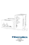
Vega MK 3
Instruction and Operation Manual
Annapolis MD USA
www.veco-na.com
USER MANUAL FOR MK3 PANEL - COMPACT & SPLIT UNITS
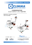
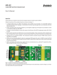
MK3 is a control system with innovative features for Climma independent units:
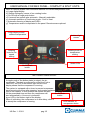
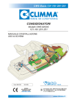
a) Large digital display
b) Simple settings by means of two rotating knobs
c) On-Off with a single push button
d) 8 manual fan speeds plus automatic - Manually selectable
e) Automatic selection of functioning mode - Cool or Heat
f) Automatic dimming of display and LED's
g) Temperature sensor incorporated in the panel. Remote sensor optional
2 digit display shows
ambient temperature
Ambient light
sensor
Rotating
knob for fan
speed
setting
Rotating knob for
temperature
setting
Mode LEDs
On-Off push
button
AIR- CONDITIONER ON-OFF
A simple push of the button starts (or stops) the airconditioner. The start is confirmed by either the Cool or
Heat LED. An LED in the bottom right corner of the
display shows that the compressor is running.
The system is equipped with a timer to prevent compressor
starts occuring too soon after stopping, and causing nuisance
trips of the breaker. In this situation the system will wait
On-Off push
for the prescribed time and then the compressor will
button
start automatically. A time-out is indicated
by an LED in the bottom-right of the display.
When it is blinking, the compressor is on time delay; when it
LED Indicator of
is steady the compressor is running.
compressor status
US Rev 1 - 2/3/11
pag.1/5
USER MANUAL FOR MK3 PANEL - COMPACT & SPLIT UNITS
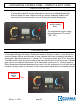
TEMPERATURE SETTING
The right side rotating knob is for adjusting the temperature set point. Touching the knob
will immediately show the current temperature set point on the display. Rotating the
knob will change the value. When the knob is released, the display will blink and
memorize the new value and then revert to showing the ambient temperature.
Temperature
setting rotating
knob
The temperature set point can be
adjusted between 65°F and 86°F
(18C - 30C)
FAN SPEED SETTING
The left rotating knob is used to set the fan speed. Touching the knob will immediately show the
actual speed setting on the display. Rotating the knob will change the value. As you release the
knob the display will blink and memorize the new value and then revert to showing the ambient
temperature. Speeds are shown as "1" through "8" ("1" being the lowest), plus "A" for "Automatic".
The MK3 control has an Automatic setting as well as a Manual option to set any of the 8 available
speeds. The Automatic setting automatically reduces the fan speed as the ambient temperature
gets closer to the set point temperature, and is selected by choosing the "A" option in the menu.
When the ambient temperature reaches the set point value the compressor turns off while the fan
remains operating. When on Automatic, the fan runs at lowest speed when the compressor stops.
Fan speed
rotating
knob
US Rev 1 - 2/3/11
pag.2/5
USER MANUAL FOR MK3 PANEL - COMPACT & SPLIT UNITS
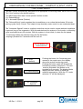
FUNCTIONING MODES
The MK3 control automatically switches to the appropriate functioning mode; either Cool or Heat.
This "Auto" setting is the default setting.
The MK3 control also has 2 more special function modes:
D = Dehumidifying
AF = Automatic Special (Defrost)
The “Dehumidifying” mode operates the air-conditioner on a routine that activates 30 minute
cooling cycles every 6 hours. This helps to keep humidity under control on an unattended boat.
The “Automatic Special” mode is a defrost mode that can be used in certain ambient conditions
to prevent icing of the evaporator. With this selected and the system in Cool mode, a defrosting
cycle is activated every 30 minutes. With the system in Heat mode, it raises the fan speed.
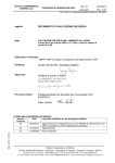
Functioning modes are selected using the On-Off button,
keeping it pressed for 5 seconds with the unit off.
On-Off button and
mode selection
A- Auto
(default)
d - Dehumidifying
Pushing the button for 5 seconds gives
access to the mode menu: the display
shows the actual functioning mode.
Pushing the button again will browse the
functioning modes in sequence. The new
mode is activated if the button is not
touched for 3 seconds. The display blinks
rapidly and then returns to show the
ambient temperature. (With the "D" mode
selected, "d" will be displayed).
AF- Automatic
Special
US Rev 1 - 2/3/11
pag.3/5
USER MANUAL FOR MK3 PANEL - COMPACT & SPLIT UNITS
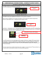
AUTOMATIC DISPLAY AND LED DIMMIMG
The MK3 control is equipped with an ambient light sensor which automatically dims the display
and LED's dependent on ambient light levels.
Ambient light
sensor
DISPLAY INDICATIONS
THE MK3 control gives additional information on the systems' functions.
When power is supplied to the system the display will show only the ambient temperature.
When no other LED's are lit, it indicates that the system is OFF.
Air-conditioner
OFF
With the A – Automatic and AF- Automatic Special Functioning modes, the LED corresponding
to the Cool or Heat mode come on together with an LED in the bottom-right corner of the display.
This LED point indicates that the compressor is running.
Compressor running (LED steady)
System in
Cool mode
The LED indicator for the compressor can be steady or blinking: A steady LED means that the
compressor is running. A blinking LED indicates that there is a timer delaying the compressor
from starting. In this condition the fan and the sea water pump will be running, while the
compressor is waiting the timer to expire. When the LED becomes steady, the compressor will
start automatically.
The timer cannot be cancelled unless the power supply is cut and restored. This procedure is not
recommended, and should be limited to the commissioning phase.
US Rev 1 - 2/3/11
pag.4/5
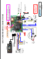
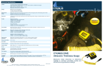
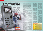
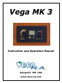
Run
Capacitor(s)
(RC)
MAINS SUPPLY
115/1/60
White
Black
White
1 DI 1
PAGINA
DATA
FUSE
S
R
14/07/2010
00
REVISIONE N°:
C
COMPRESSOR
Black
MK3 POWERBOARD CONNECTIONS.VSD
ING. MARCO BRIVIO
AUTORE
NOME FILE
(May also be a DC
pump operated via
a relay)
110v or 230v AC Pump
Y/G
Y/G
External Probe
(Optional)
COMPRESSOR START
DELAY TIMER 2 10 s
BLUE
J1- °C/°F
BLUE
Y/G
WHITE
on
BLUE
FAN
Heater
BLACK
BLACK
RW 2/3/11
C835
ATTENTION:
Electrical Heater is NOT
supported with 115 V
Power Supply. Use a relay.
HIGH PRESSURE SWITCH
(HP) N.C(HPS)
contact
ON when HPS is open = alarm engaged
HPS LED
ON when Board is POWERED
POWER LED
1-ON / 2-ON = P0 = COOL ONLY Unit (CO)
1-ON / 2-OFF = P1 = Unit with ELECTRICAL HEATING (EH)
1-OFF / 2-ON = P2 = Unit with REVERSE CYCLE (RC)
1-OFF / 2-OFF = nP = No Program Selected
DIP SWITCH LEGEND
Reversing Valve
2
1
MODE
SWITCH
MODE
SWITCH
For deg F
bridge J1
Y/G
DGT PANEL
VEGA MK3
MK3 POWERBOARD CONNECTIONS
BLACK
BLUE