1
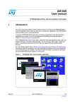
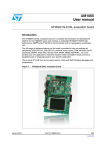
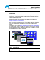
UM1069
User manual
STM3220G-EVAL/STM3221G-EVAL demonstration firmware
Introduction
This user manual describes the demonstration firmware running on the STM3220G-EVAL
(Rev. B) evaluation board, which can be used to evaluate the capabilities of the STM32F2xx
microcontrollers and on-board peripherals. The demonstration firmware also runs on the
STM3221G-EVAL evaluation board.
In case the STM3220G-EVAL board was not factory-programmed or the demonstration
application was erased, it can be re-programmed by following the steps described in
Chapter 3: Programming the demonstration.
The STM3220G-EVAL board comes with a USB Flash disk preprogrammed with audio and
images resources used by the demonstration. You can load your own image (*.bmp) and
audio (*.wav) files provided that the file formats are supported by the demonstration
firmware.
For more details, please refer to Section 2.5: Image browser and Section 2.8: Audio player.
The default audio files available in the USB Flash disk are based on free music downloads
from the DanoSongs.com website. This demonstration firmware is available for download
from the STMicroelectronics website at www.st.com.
Figure 1.
STM3220G-EVAL demonstration application
Table 1 lists the development tools concerned by this user manual.
Table 1.
Applicable tools
Type
Development tools
November 2012
Applicable tools
STM3220G-EVAL, STM3221G-EVAL
Doc ID 018665 Rev 3
1/21
www.st.com
Contents
UM1069
Contents
1
Demonstration architecture overview . . . . . . . . . . . . . . . . . . . . . . . . . . . 5
1.1
Hardware resources . . . . . . . . . . . . . . . . . . . . . . . . . . . . . . . . . . . . . . . . . . 5
1.2
Hardware configuration . . . . . . . . . . . . . . . . . . . . . . . . . . . . . . . . . . . . . . . 6
1.3
2
1.2.1
Required accessories . . . . . . . . . . . . . . . . . . . . . . . . . . . . . . . . . . . . . . . 6
1.2.2
Jumper configurations . . . . . . . . . . . . . . . . . . . . . . . . . . . . . . . . . . . . . . . 7
Firmware architecture . . . . . . . . . . . . . . . . . . . . . . . . . . . . . . . . . . . . . . . . 7
Demonstration architecture overview . . . . . . . . . . . . . . . . . . . . . . . . . . . 9
2.1
Navigation procedure . . . . . . . . . . . . . . . . . . . . . . . . . . . . . . . . . . . . . . . . . 9
2.2
Demo startup . . . . . . . . . . . . . . . . . . . . . . . . . . . . . . . . . . . . . . . . . . . . . . . 9
2.3
USB console . . . . . . . . . . . . . . . . . . . . . . . . . . . . . . . . . . . . . . . . . . . . . . . 10
2.4
System info . . . . . . . . . . . . . . . . . . . . . . . . . . . . . . . . . . . . . . . . . . . . . . . . 10
2.5
Image browser . . . . . . . . . . . . . . . . . . . . . . . . . . . . . . . . . . . . . . . . . . . . . 11
2.6
Web server . . . . . . . . . . . . . . . . . . . . . . . . . . . . . . . . . . . . . . . . . . . . . . . . 12
2.7
USB joystick . . . . . . . . . . . . . . . . . . . . . . . . . . . . . . . . . . . . . . . . . . . . . . . 15
2.8
Audio player . . . . . . . . . . . . . . . . . . . . . . . . . . . . . . . . . . . . . . . . . . . . . . . 16
2.9
Analog clock . . . . . . . . . . . . . . . . . . . . . . . . . . . . . . . . . . . . . . . . . . . . . . . 17
2.10
Camera . . . . . . . . . . . . . . . . . . . . . . . . . . . . . . . . . . . . . . . . . . . . . . . . . . . 18
2.11
Sub-demo interaction . . . . . . . . . . . . . . . . . . . . . . . . . . . . . . . . . . . . . . . . 18
3
Programming the demonstration . . . . . . . . . . . . . . . . . . . . . . . . . . . . . . 19
4
Revision history . . . . . . . . . . . . . . . . . . . . . . . . . . . . . . . . . . . . . . . . . . . 20
2/21
Doc ID 018665 Rev 3
UM1069
List of tables
List of tables
Table 1.
Table 2.
Table 3.
Table 4.
Table 5.
Applicable products and tools . . . . . . . . . . . . . . . . . . . . . . . . . . . . . . . . . . . . . . . . . . . . . . . . 1
Jumper configurations . . . . . . . . . . . . . . . . . . . . . . . . . . . . . . . . . . . . . . . . . . . . . . . . . . . . . 7
Supported bitmap formats . . . . . . . . . . . . . . . . . . . . . . . . . . . . . . . . . . . . . . . . . . . . . . . . . 12
Audio file configurations . . . . . . . . . . . . . . . . . . . . . . . . . . . . . . . . . . . . . . . . . . . . . . . . . . . 16
Document revision history . . . . . . . . . . . . . . . . . . . . . . . . . . . . . . . . . . . . . . . . . . . . . . . . . 20
Doc ID 018665 Rev 3
3/21
List of figures
UM1069
List of figures
Figure 1.
Figure 2.
Figure 3.
Figure 4.
Figure 5.
Figure 6.
Figure 7.
Figure 8.
Figure 9.
Figure 10.
Figure 11.
Figure 12.
Figure 13.
Figure 14.
Figure 15.
Figure 16.
Figure 17.
Figure 18.
Figure 19.
Figure 20.
Figure 21.
Figure 22.
Figure 23.
Figure 24.
Figure 25.
Figure 26.
4/21
STM3220G-EVAL demonstration application . . . . . . . . . . . . . . . . . . . . . . . . . . . . . . . . . . . . 1
Hardware block diagram . . . . . . . . . . . . . . . . . . . . . . . . . . . . . . . . . . . . . . . . . . . . . . . . . . . . 5
Hardware configuration . . . . . . . . . . . . . . . . . . . . . . . . . . . . . . . . . . . . . . . . . . . . . . . . . . . . 6
USB Flash disk tree structure . . . . . . . . . . . . . . . . . . . . . . . . . . . . . . . . . . . . . . . . . . . . . . . . 6
Firmware architecture . . . . . . . . . . . . . . . . . . . . . . . . . . . . . . . . . . . . . . . . . . . . . . . . . . . . . 7
Startup screen during initialization phase . . . . . . . . . . . . . . . . . . . . . . . . . . . . . . . . . . . . . . . 9
Main desktop (icon view widget) . . . . . . . . . . . . . . . . . . . . . . . . . . . . . . . . . . . . . . . . . . . . . 9
USB console frame window . . . . . . . . . . . . . . . . . . . . . . . . . . . . . . . . . . . . . . . . . . . . . . . . 10
First frame window . . . . . . . . . . . . . . . . . . . . . . . . . . . . . . . . . . . . . . . . . . . . . . . . . . . . . . . 10
Second frame window . . . . . . . . . . . . . . . . . . . . . . . . . . . . . . . . . . . . . . . . . . . . . . . . . . . . 11
Third frame window . . . . . . . . . . . . . . . . . . . . . . . . . . . . . . . . . . . . . . . . . . . . . . . . . . . . . . 11
Image browser . . . . . . . . . . . . . . . . . . . . . . . . . . . . . . . . . . . . . . . . . . . . . . . . . . . . . . . . . . 11
Web server DHCP server reply . . . . . . . . . . . . . . . . . . . . . . . . . . . . . . . . . . . . . . . . . . . . . 12
Connection properties screen . . . . . . . . . . . . . . . . . . . . . . . . . . . . . . . . . . . . . . . . . . . . . . . 13
TCP/IP properties screen . . . . . . . . . . . . . . . . . . . . . . . . . . . . . . . . . . . . . . . . . . . . . . . . . . 13
Connection status screen . . . . . . . . . . . . . . . . . . . . . . . . . . . . . . . . . . . . . . . . . . . . . . . . . . 14
HID properties screen . . . . . . . . . . . . . . . . . . . . . . . . . . . . . . . . . . . . . . . . . . . . . . . . . . . . . 15
USB joystick status screen . . . . . . . . . . . . . . . . . . . . . . . . . . . . . . . . . . . . . . . . . . . . . . . . . 15
Audio player diagram . . . . . . . . . . . . . . . . . . . . . . . . . . . . . . . . . . . . . . . . . . . . . . . . . . . . . 16
Audio player interface . . . . . . . . . . . . . . . . . . . . . . . . . . . . . . . . . . . . . . . . . . . . . . . . . . . . . 16
Analog clock window . . . . . . . . . . . . . . . . . . . . . . . . . . . . . . . . . . . . . . . . . . . . . . . . . . . . . 17
Analog clock configuration window . . . . . . . . . . . . . . . . . . . . . . . . . . . . . . . . . . . . . . . . . . . 17
Analog clock date and time format . . . . . . . . . . . . . . . . . . . . . . . . . . . . . . . . . . . . . . . . . . . 17
Analog clock error message . . . . . . . . . . . . . . . . . . . . . . . . . . . . . . . . . . . . . . . . . . . . . . . . 17
Camera diagram . . . . . . . . . . . . . . . . . . . . . . . . . . . . . . . . . . . . . . . . . . . . . . . . . . . . . . . . . 18
Capture screen . . . . . . . . . . . . . . . . . . . . . . . . . . . . . . . . . . . . . . . . . . . . . . . . . . . . . . . . . . 18
Doc ID 018665 Rev 3
UM1069
Demonstration architecture overview
1
Demonstration architecture overview
1.1
Hardware resources
The demonstration firmware mainly uses the following two peripherals which are major
features of the STM32F2xx device:
●
Ethernet (web server)
●
USB on-the-go: the USB OTG Full Speed (FS) is used in Host mode for audio and
image media storage while the USB OTG High Speed (HS) is used for the USB Human
Interface Device (HID) applications
The firmware makes use of other STM32 peripherals for demonstration purposes:
●
User interface: color display, LEDs, event input (keys, touch screen)
●
I2S IP for the audio (.wav file) player
●
Digital camera interface (DCMI) for the camera application
●
RTC IP for the clock application
Other STM32 hardware features are used globally by the demonstration application and the
software environment (for example, the SysTick timer for the real-time operating system
(RTOS), the I2C for the IO expander used by the touch screen, etc.).
The camera application also uses the SRAM embedded on the STM3220G-EVAL board to
store the camera frames via the DMA before they are output to the display through the GUI.
Figure 2.
Hardware block diagram
Doc ID 018665 Rev 3
5/21
Demonstration architecture overview
1.2
Hardware configuration
Figure 3.
1.2.1
UM1069
Hardware configuration
Required accessories
In addition to the STM3220G-EVAL board, the demonstration requires the following
accessories:
●
Micro-AB to standard receptacle A connector (provided with STM3220G-EVAL board
package)
●
Micro-AB to standard plug A connector (provided with STM3220G-EVAL board
package)
●
Headphone with male jack connector
●
USB Flash disk (provided with STM3220G-EVAL board package)
Figure 4.
6/21
USB Flash disk tree structure
Doc ID 018665 Rev 3
UM1069
1.2.2
Demonstration architecture overview
Jumper configurations
Table 2.
Jumper configurations
Jumper
1.3
Usage
Configuration
Note
JP5
Ethernet
2 <-> 3
25 MHz clock provided by MCO
JP6
Ethernet
2 <->3
MII interface mode is enabled
JP8
Ethernet
Open
MII interface mode is enabled
JP19
RTC
JP31
USB OTG HS
SW1
Boot mode
1 <-> 2
STM3220G-EVAL boot from User Flash
SW1
Boot mode
1 <-> 2
STM3220G-EVAL boot from User Flash
2 <-> 3
RTC powered by embedded battery
Fitted
USB OTG HS selected
Firmware architecture
The demonstration is built with a modular architecture based on a real time operating
system and uses a graphical windowing system based on the uC-OSII RTOS from Micrium
and the emWin graphical stack from Segger.
The system configuration and the standard peripheral settings and configuration are made
through the STM32F2xx Standard Peripheral Library.
Data used by the application is stored in the external USB Flash disk through a FAT file
system (emFile from Segger) in order to save space in the STM32 internal Flash memory.
Figure 5.
Firmware architecture
Application Layer
Audio
Player
Camera
Snapshot
USB Device
Touchpad
Web
Server
FAT
File System
Ethernet
components:
HTTP, DHCP,
FTP, etc.
Stacks and Libraries
USB Device
Stack
LCD
Touchscreen
Joystick
Control
USB Host
Stack
Misc:
Calendar, Time,
System Information
Misc. apps:
Calendar, Time,
System Monitoring,
System Information
Ethernet
Stack
USB OTG
Low-level driver
Ethernet
Driver
Real-Time Operating System
GUI Library
DCMI
Flow and Capture
Management
Image
Browser
STM32 Standard
Firmware Library
Driver Layer
MS18180V1
Doc ID 018665 Rev 3
7/21
Demonstration architecture overview
UM1069
The demonstration application is built using the following software components:
8/21
1.
STM32F2xx Standard Peripheral Library V1.0.0
2.
µC-OSII RTOS (Version 2.86)
3.
µC-USB Host stack (Version 3.0)
4.
emWin Graphical stack (Version 3.10)
5.
emFile file system (Version 4.16 from Segger)
6.
LwIP TCP/IP stack (Version1.3.1)
Doc ID 018665 Rev 3
UM1069
2
Demonstration architecture overview
Demonstration architecture overview
The STM3220G-EVAL demonstration consists of seven sub-demos and uses the emWin
graphical stack for the visual aspect, uC-Host stack and uC-FS for media storage in the
connected USB Flash disk; the embedded touch screen is used as an input device (one
touch mode) and the LCD is used in 16-bit color mode.
2.1
Navigation procedure
The STM3220G-EVAL demonstration is an interactive application; the navigation within subdemos is done by a single touch using a pen or finger on the active touch screen.
2.2
Demo startup
The application starts in text mode until the initialization phase is completed.
Figure 6.
Startup screen during initialization phase
After initializing the hardware, the involved peripherals and the GUI stacks, the main desktop
displays all the available sub-demos through the icon view widget.
Figure 7.
Main desktop (icon view widget)
Doc ID 018665 Rev 3
9/21
Demonstration architecture overview
2.3
UM1069
USB console
The USB console frame window shows the USB Host connectivity state. The USB Disk
Flash Connected message means that the USB Flash disk is configured and ready for use.
Figure 8.
2.4
USB console frame window
System info
The system info sub-demo is composed of three window frames. The user can use the
forward and back buttons to navigate within the three windows while the Exit button ends the
sub-demo and displays the main menu (Icon view).
The first frame window (Figure 9) shows the hardware and software revisions and the
STM32 hardware resources (RAM and Flash size).
Figure 9.
10/21
First frame window
Doc ID 018665 Rev 3
UM1069
Demonstration architecture overview
The second frame window (Figure 10) indicates the instant CPU usage in percentage (%);
the graphical widget is updated every second.
Figure 10. Second frame window
The third frame window (Figure 11) shows the different priorities and memory usage of the
running tasks.
Figure 11. Third frame window
The task list is arranged by priority order; the user can click on the Prio tab to invert the
order of the priorities. The memory usage is given in bytes and corresponds to the internal
stack size of the corresponding running task.
Note:
The task list is not updated dynamically when a new sub-demo is launched; the user should
exit and launch again the task window by using the forward and back buttons to update the
list of tasks.
2.5
Image browser
The Image browser displays the bitmap (BMP) files stored in the “Images” directory from the
connected USB Flash disk (connected to the USB OTG FS port). The Image browser
automatically resizes the image to fit in the display area.
Figure 12. Image browser
Doc ID 018665 Rev 3
11/21
Demonstration architecture overview
UM1069
The user can enable/disable the automatic slide show by clicking on the picture; when the
automatic slide show is enabled, the images are changed every second.
The user can also select the image to show from the list displayed in the right of the Image
browser window frame.
Table 3 shows the different supported BMP formats.
Table 3.
2.6
Supported bitmap formats
Bits per pixel
Indexed
Compression
Supported
1
Yes
No
Yes
4
Yes
No
Yes
4
Yes
Yes
Yes
8
Yes
No
Yes
8
Yes
Yes
Yes
16
No
No
Yes
24
No
No
Yes
32
No
No
Yes
Web server
This demonstration is an embedded web server based on the lwIP stack. It allows
addressing the STM3220G-EVAL board as a web page using your web browser to control
the four LEDs on the board and the potentiometer level.
The STM32 Ethernet peripheral is configured in MII mode with speed auto negotiation and
the Clock for the external PHY is provided by the STM32 through the MCO pin.
Figure 13. Web server DHCP server reply
The web server sub-demo supports the DHCP protocol and, if the DHCP is enabled in the
host side, an automatic IP address is assigned to the board; otherwise, a static IP address is
used instead (192.168.0.8).
12/21
Doc ID 018665 Rev 3
UM1069
Demonstration architecture overview
How to use the web server demonstration
1.
Ensure that the jumper configuration on your STM3220G-EVAL board is correct (refer
to Table 2: Jumper configurations on page 7).
2.
Modify your PC network configuration:
a) Disable the Internet firewall installed on your PC (if it is enabled) and
bypass/deselect any proxy server in use.
b)
Set your PC network card “Speed & Duplex” property to “Auto Navigation”: under
Windows, select Control Panel > Network Connections > Local Area
Connection > Properties > Configure > Advanced > Speed & Duplex.
Figure 14. Connection properties screen
c)
If the DHCP is not supported, change your PC IP address to 192.168.0.x (x
different from 8). To do this, under Windows, select Control Panel > Network
Connections > Local Area Connection > Properties > Internet Protocol
(TCP/IP) > Properties > and use the following IP address.
Figure 15. TCP/IP properties screen
Doc ID 018665 Rev 3
13/21
Demonstration architecture overview
d)
UM1069
If the DHCP is supported, enable the DHCP and the STM3220G-EVAL board will
automatically acquire an IP address.
Figure 16. Connection status screen
14/21
3.
In point-to-point configuration, connect your PC to the STM3220G-EVAL board using
an Ethernet cross cable.
4.
In a local network, connect the STM3220G-EVAL board to the network hub using an
Ethernet regular cable.
5.
Ping the board by typing in the DOS command window: “ping xx.xx.xx.xx” where
xx.xx.xx.xx is the DHCP or the statically assigned IP address.
6.
In your internet browser, type “http:// xx.xx.xx.xx” to load the STM32 web page.
7.
Now you can turn on/off the four LEDs on the STM3220G-EVAL board.
Doc ID 018665 Rev 3
UM1069
2.7
Demonstration architecture overview
USB joystick
The HID example uses the joystick embedded in the STM3220G-EVAL evaluation board.
The HID example works in High Speed mode (the USB OTG HS connector is used).
Figure 17. HID properties screen
Once connected and correctly configured, the STM3220G-EVAL board acts as a USB HID
joystick device and the user can move the mouse pointer on the Host by using the Up, Left,
Down and Right buttons.
Figure 18. USB joystick status screen
Doc ID 018665 Rev 3
15/21
Demonstration architecture overview
2.8
UM1069
Audio player
The audio player retrieves the WAV files stored in the “Audio” directory in the connected
USB Flash disk (connected to the USB OTG FS port).
Figure 19. Audio player diagram
The user can Stop/Play/Resume/Go Back/ Forward and Mute the audio sample and can
select the title to be played directly from the playlist.
Figure 20. Audio player interface
The user can use a headset or the embedded speaker to output the audio sample. The
peripheral is detected automatically: when the headset is removed, the speaker is
automatically used. The audio player supports all WAV PCM audio files with the
configuration listed in Table 4.
Table 4.
Audio file configurations
Parameter
Value
Sample rate
8 to 96 kHz
Channel number
Stereo/Mono
Audio Data Format
Note:
16/21
16 bits
This limitation is due to the audio codec used on the STM3220G-EVAL board which accepts
a fixed Master Clock frequency while the STM32F2xx I2S provides a Master clock at a fixed
rate of 256 x fS (where fS is the audio sampling rate). It is recommended to use the headset
when listening to audio files with a sample rate below 32 Hz, and use a headset or speaker
for other audio files.
Doc ID 018665 Rev 3
UM1069
2.9
Demonstration architecture overview
Analog clock
The analog clock window shows the system clock (RTC) on an analog background, and also
the current date on the caption of the frame window.
Figure 21. Analog clock window
To configure the clock and the date, the user can click the Set button to display a second
frame window with a numerical pad used to easily set the clock and the date.
Figure 22. Analog clock configuration window
The date and the clock display use the following format.
Figure 23. Analog clock date and time format
Time:
Date:
hh:mm:ss
dd\mm\yyyy
If the format is not correct, an error message (Figure 24) is displayed and the user should
re-enter a valid value.
Figure 24. Analog clock error message
Doc ID 018665 Rev 3
17/21
Demonstration architecture overview
2.10
UM1069
Camera
The camera demo obtains raw data from the camera module and displays it on the LCD
through the GUI core.
Figure 25. Camera diagram
The user can use the capture button to take a snapshot of the video and display only a
single frame on the LCD. Pressing again the capture button restores the continuous display
mode.
Figure 26. Capture screen
Video frame
Slider to change
brightness
2.11
Sub-demo interaction
Due to the intensive CPU use of some parts of the application (GUI refresh and access to
the USB Flash disk), some sub-demos cannot be run at the same time.
In order to reduce this interaction and reduce the time needed by the GUI to refresh the
displayed windows, only the USB Console window and the clock are allowed to run when
the Audio Player is running. This is considered as an “exclusive” sub-demo, which means
that the user cannot run the Audio Player and another sub-demo at the same time. When
the user attempts to launch an exclusive sub-demo, a message box is displayed to inform
the user that an exclusive sub-demo is already running.
18/21
Doc ID 018665 Rev 3
UM1069
3
Programming the demonstration
Programming the demonstration
Normally, the STM3220G-EVAL demo is included with the board and the necessary
accessories described in Section 1.2.1: Required accessories. However, the user can
program the board by using the binary file included with the demo package (in the \Binary
folder).
Note:
Demonstration binary files are provided also for the legacy STM3220F-EVAL board Rev. A.
“_vx_y_z” in the file name refers to the version of the demonstration firmware.
You can program the demonstration using either the EWARM or the Bootloader method.
Using the EWARM (v6.10 and later) preconfigured project
1.
Open the EWARM\Flash_Loader.ewd workspace.
2.
Open Project > Download > Download file, and select the *.out file to program:
3.
–
Load the Binary\STM3220G-EVAL_FW_vx_y_z.out file for the STM3220G-EVAL
Rev. B
–
Load the Binary\STM3220F-EVAL_FW_vx_y_z.out file for the STM3220F-EVAL
Rev. A
Once the binary is programmed, remove the JTAG probe and restart the board.
Using the Bootloader
Depending on the Bootloader serial interface you are using, you have to proceed as follows:
1.
2.
3.
For USART or CAN interfaces:
a)
Load the Binary\STM3220G-EVAL_FW_vx_y_z.bin file for the STM3220G-EVAL
Rev. B
b)
Load the Binary\STM3220F-EVAL_FW_vx_y_z.bin file for the STM3220F-EVAL
Rev. A
For USB FS Device mode (DFU) interface:
a)
Load the Binary\STM3220G-EVAL_FW_vx_y_z.dfu file for the STM3220G-EVAL
Rev. B
b)
Load the Binary\STM3220F-EVAL_FW_vx_y_z.dfu file for the STM3220F-EVAL
Rev. A
Once the binary is programmed, configure the boot pins to the “Boot from Flash”
position and restart the board.
For more information about the STM32F2xx Bootloader, please refer to AN2606, STM32
microcontroller system memory boot mode.
Doc ID 018665 Rev 3
19/21
Revision history
4
UM1069
Revision history
Table 5.
20/21
Document revision history
Date
Revision
Changes
20-Apr-2011
1
Initial release.
10-May-2011
2
Updated document for STM3220G-EVAL (Rev. B) evaluation board
only.
16-Nov-2012
3
Added STM3221G-EVAL to the title and the Introduction.
Fixed a few typos, among them a list numbering in How to use the
web server demonstration.
Doc ID 018665 Rev 3
UM1069
Please Read Carefully:
Information in this document is provided solely in connection with ST products. STMicroelectronics NV and its subsidiaries (“ST”) reserve the
right to make changes, corrections, modifications or improvements, to this document, and the products and services described herein at any
time, without notice.
All ST products are sold pursuant to ST’s terms and conditions of sale.
Purchasers are solely responsible for the choice, selection and use of the ST products and services described herein, and ST assumes no
liability whatsoever relating to the choice, selection or use of the ST products and services described herein.
No license, express or implied, by estoppel or otherwise, to any intellectual property rights is granted under this document. If any part of this
document refers to any third party products or services it shall not be deemed a license grant by ST for the use of such third party products
or services, or any intellectual property contained therein or considered as a warranty covering the use in any manner whatsoever of such
third party products or services or any intellectual property contained therein.
UNLESS OTHERWISE SET FORTH IN ST’S TERMS AND CONDITIONS OF SALE ST DISCLAIMS ANY EXPRESS OR IMPLIED
WARRANTY WITH RESPECT TO THE USE AND/OR SALE OF ST PRODUCTS INCLUDING WITHOUT LIMITATION IMPLIED
WARRANTIES OF MERCHANTABILITY, FITNESS FOR A PARTICULAR PURPOSE (AND THEIR EQUIVALENTS UNDER THE LAWS
OF ANY JURISDICTION), OR INFRINGEMENT OF ANY PATENT, COPYRIGHT OR OTHER INTELLECTUAL PROPERTY RIGHT.
UNLESS EXPRESSLY APPROVED IN WRITING BY TWO AUTHORIZED ST REPRESENTATIVES, ST PRODUCTS ARE NOT
RECOMMENDED, AUTHORIZED OR WARRANTED FOR USE IN MILITARY, AIR CRAFT, SPACE, LIFE SAVING, OR LIFE SUSTAINING
APPLICATIONS, NOR IN PRODUCTS OR SYSTEMS WHERE FAILURE OR MALFUNCTION MAY RESULT IN PERSONAL INJURY,
DEATH, OR SEVERE PROPERTY OR ENVIRONMENTAL DAMAGE. ST PRODUCTS WHICH ARE NOT SPECIFIED AS "AUTOMOTIVE
GRADE" MAY ONLY BE USED IN AUTOMOTIVE APPLICATIONS AT USER’S OWN RISK.
Resale of ST products with provisions different from the statements and/or technical features set forth in this document shall immediately void
any warranty granted by ST for the ST product or service described herein and shall not create or extend in any manner whatsoever, any
liability of ST.
ST and the ST logo are trademarks or registered trademarks of ST in various countries.
Information in this document supersedes and replaces all information previously supplied.
The ST logo is a registered trademark of STMicroelectronics. All other names are the property of their respective owners.
© 2012 STMicroelectronics - All rights reserved
STMicroelectronics group of companies
Australia - Belgium - Brazil - Canada - China - Czech Republic - Finland - France - Germany - Hong Kong - India - Israel - Italy - Japan Malaysia - Malta - Morocco - Philippines - Singapore - Spain - Sweden - Switzerland - United Kingdom - United States of America
www.st.com
Doc ID 018665 Rev 3
21/21