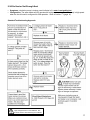
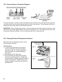
1
STANDARD TROUBLESHOOTING APPROACH
y
Display
y
Mode
Cycle
Select
S.T.A. Manual
2002+ Jacuzzi Premium
Protech LCD Model Hot Tubs
P R E M I U M
Table of Contents
Chapter
Page
1.0
Standard Troubleshooting Approach (S.T.A.) ........................................................................... 1
1.1
Why a Standard Troubleshooting Approach? ................................................................................ 1
1.2
How to Use the STA. ..................................................................................................................... 1
1.3
Professional Customer Service ..................................................................................................... 1
1.4
Before Leaving the Shop ............................................................................................................... 1
1.5
Fixing the Hot Tub ......................................................................................................................... 1
1.6
Before Calling Technical Support .................................................................................................. 1
1.7
Before Leaving the Customer ....................................................................................................... 2
1.8
The Trouble Log ............................................................................................................................ 2
1.9
Satisfying the Customer ................................................................................................................ 2
2.0
2.1
2.2
2.3
2.4
Electro Static Discharge (E.S.D.) ............................................................................................... 3
ESD - What is it? What does it do? ............................................................................................... 3
Avoiding ESD Damage .................................................................................................................. 3
What About Wrist Straps and Special Mats? ................................................................................ 3
Must Wrist Straps and Mats be Used When Replacing A Circuit Board? ..................................... 3
3.0
4.0
Main System Specifications ....................................................................................................... 4
Main Control Panel Functions ................................................................................................... 5
5.0
5.1
5.2
5.3
5.4
5.5
5.6
5.6A
5.6B
5.6C
5.6D
5.7
Troubleshooting Using The Control Panel ................................................................................ 6
Control Panel Displays .................................................................................................................. 6
Control Panel Default Display........................................................................................................ 6
Control Panel Status and Error Messages .................................................................................... 6
Control Panel Displays without Service Jumper Installed ............................................................. 7
Control Panel Displays with Service Jumper Installed (Trouble Log) ............................................ 7
Programming Control Panel without Service Jumper Installed (Sections 5.6A-5.6G) .................. 8
Programming the Time of Day ...................................................................................................... 8
Programming Filter Cycles ............................................................................................................ 9
Programming the Circulation Pump .............................................................................................. 9
Locking the Filter Cycle ................................................................................................................. 10
Programming Control Panel with Service Jumper Installed .......................................................... 11
6.0
6.1
6.2
6.3
6.5
6.6
6.7
6.8
6.9
6.10
6.11
Additional Control Panel Functions .......................................................................................... 11
Temperature Setting ...................................................................................................................... 11
Selecting Standard/Economy Modes ............................................................................................ 11
Selecting Jets Speed .................................................................................................................... 12
Multi-Colored LED Light Operation ............................................................................................... 12
Lock Control Panel ........................................................................................................................ 13
Unlock Control Panel ..................................................................................................................... 13
Enable Temperature Lock ............................................................................................................. 13
Disable Temperature Lock ............................................................................................................. 13
Lock Filter Cycles .......................................................................................................................... 13
Unlock Filter Cycles ...................................................................................................................... 13
7.0
Understanding Circuit Board Pin Assignments ......................................................................... 14
7.1
JP9 Jumper Functions .................................................................................................................... 14
7.2
JP19 Jumper Pin Configurations .................................................................................................... 14
7.3
JP20 Jumper Pin Configurations .................................................................................................... 14
Chapter
Page
8.0
Protech LCD ProClear System Logic .......................................................................................... 15
9.0
9.1
9.2
9.3
9.4
9.5
9.6
9.7
9.8
9.9
9.10
9.11
9.12
9.13
9.14
Troubleshooting without The Control Panel ............................................................................... 16
Approaching the Hot Tub - First Steps ............................................................................................ 16
No Heat or Not Enough Heat (Diagrams 9.2A-9.2E) ...................................................................... 16
Intermittent Heating ........................................................................................................................ 22
Nothing Works ................................................................................................................................. 22
Hot Tub Doesn’t Come On for Filter Cycle ...................................................................................... 23
House Breaker Trips ........................................................................................................................ 24
Hot Tub Light Will Not Come On ..................................................................................................... 25
No Jets ............................................................................................................................................ 26
Weak or Surging Jets ...................................................................................................................... 27
Pump Runs and Quits During Jets Mode ....................................................................................... 28
Circulation Pump Not Working ........................................................................................................ 29
Troubleshooting A Thermal Pump Cutout ....................................................................................... 30
Pump Hums and Will Not Start ....................................................................................................... 30
Ozone Not Working ......................................................................................................................... 31
A.
A1.
A2.
A3.
A4.0
A4.1
A4.2
A4.3
A5.
A6.
A7.
A8.
A9.
A10.
A11.
A12.
A13.
A14.
A15.
A16.
A17.
A18.
A19.
Appendix ........................................................................................................................................ 33
Checking Voltage to Hot Tub ........................................................................................................... 34
Checking Voltage to Devices ........................................................................................................... 34
Checking Current Consumption of Devices .................................................................................... 35
The Test Plug .................................................................................................................................. 35
When to Use the Test Plug ............................................................................................................. 35
How to Use the Test Plug ................................................................................................................ 35
Interpreting the Results ................................................................................................................... 36
Testing the Flow Switch .................................................................................................................. 36
About Fuses .................................................................................................................................... 37
The Watchdog ( - - - - ) ................................................................................................................... 38
Understanding Ozone ..................................................................................................................... 38
2002 Protech LCD Series Circuit Board Illustration (240 VAC / 3-Wire Connection) ...................... 39
2002 Protech LCD Series Circuit Board Illustration w/Stereo (240 VAC / 3-Wire Connection) ...... 40
Load Box Connection Diagrams A-B .............................................................................................. 41
Temperature / Hi-limit Sensor Resistance Chart............................................................................. 42
Transformer Test ............................................................................................................................. 43
Flow Switch Illustration ................................................................................................................... 43
Sensor Harness Connector Diagram .............................................................................................. 44
Testing Hi-limit and Temperature Sensors ...................................................................................... 44
Suggested Spare Parts ................................................................................................................... 45
Glossary of Terms ........................................................................................................................... 46
Sample Troubleshooting Data Collection Form ............................................................................... 47
1.0 Standard Troubleshooting Approach (S.T.A.)
1.1 Why a Standard Troubleshooting Approach?
Service prices are basically set by local industry and geographic region. Stiff competition in the service
industry has made it difficult to raise the price of a service contract; or charge more for time and materials
than the competitive shop down the street. If your service business is to be profitable you must control the
overall cost of service. The total cost of service is made up of many individual cost factors, but three in
particular are more important than the rest combined:
1. Time of Repair - How long it takes to find and fix a problem.
2. Time Between Failures - How often you are called to repair any one particular hot tub? How many
times are you called back to fix the same problem on the same hot tub?
3. Parts Usage - Except in rare circumstances, only one part fails. How many parts do you replace before
you find the bad one?
The Jacuzzi Premium STA manual has been designed to help you control the overall cost of service by
focusing on the three important aspects of your job outlined above. The STA will help you fix your
customer’s hot tub quickly, fix it well, and use fewer parts.
1.2 How to Use the STA
The STA was developed by the Jacuzzi Premium Technical Support Department and is
designed to be the communications link between you and your customers. If you call
for help on any symptom covered in this book, you will be told to do what the STA
recommends, therefore, you will save time by calling technical support after you have
done what the STA tells you to do.
1.3 Professional Customer Service
Doing your job in a way that keeps cost of service low and profit margin high also creates customer
satisfaction. That’s being a professional!
1.4 Before Leaving the Shop
Phone the customer(s), personally if possible, and ask what problem(s) should be
corrected. This may not tell you what work must be done or what part(s) must be
replaced, but it will tell you what you must fix after you arrive.
1.5 Fixing the Hot Tub
Use the STA to see how Jacuzzi Premium Technical Support Department would approach the customer’s
complaint. Try to fix the problem following the STA. Use your experience and other information to help you
answer any “Whys” or “Hows”. The STA is designed to keep unnecessary part replacement to a minimum.
Least expensive, most likely, and easily changed parts are always swapped first. Some parts, like control
panels and temperature sensors do not require complete installation to be temporarily swapped out for
testing purposes. You should carry such spares as “Tools”. Refer to suggested spare parts, page 45.
1.6 Before Calling Technical Support
Make sure you have followed the STA and filled out a “Troubleshooting Data Collection Form”
(see example on page 47). Have the STA manual and the Troubleshooting Data Worksheet
near the telephone. Technical Support can help you best if these two things become the
communications tools for the phone call.
1
1.7 Before Leaving the Customer
Even if you didn’t have to fill out a Troubleshooting Data Collection Form, please do so. If this is a warranty
repair, the information will be needed when your office fills out the “Returned Goods/Labor Tag.” In any
case, it will help you spot trouble before it happens. Pumps burn up if voltage at the hot tub is too low.
Circuit breakers trip if heaters and motors draw too much current (Amps). Wires overheat and connections
burn if wire size is too small or push-on connectors are loose. Call backs cause cost of service to
increase!
1.8 The Trouble Log
Intermittent problems, frequent circuit board and pump replacement, and vague complaints of “sometimes”
unsatisfactory hot tub performance, are all major headaches for the owner, technician, dealer, and
Jacuzzi Premium. Temporary conditions like temperature extremes, low line voltage, and line voltage
fluctuations are often the culprits, but how can you prove such events happened unless a technician sits
around the hot tub for days with thermometers, voltmeters, and log books? With the Trouble Log, that’s
how! The Trouble Log is an automatically updating memory built into the control system. If the Trouble Log
is reset at the end of a service call, it will monitor and record:
1.
2.
3.
4.
5.
Highest, present, and lowest line voltages as a percentage of 240 VAC.
Highest, present, and lowest temperature sensed by the hi-limit/freeze sensor.
Highest, present, and lowest temperature of the circuit board in the load box.
Displays selected line voltage frequency in Hz (cycles-per-second).
pH Adjustment Factor (feature discontinued).
This information helps you diagnose the cause of the customer complaints rather than guess at them. It
can help you to control callback costs, and increase customer satisfaction by controlled problem resolution
rather than the try-something-and-hope technique.
This data will help Jacuzzi Premium improve product quality by observing the relationship between
environmental conditions and designing equipment that can withstand whatever mother nature and the
supply voltage can throw at it.
The data from the Trouble Log can only help if it is:
1. Read on each service call,
2. Recorded accurately on each warranty claim form,
3. Reset to present values at the end of the service call by displaying each record and pressing the
COOLER
button while displayed.
1.9 Satisfying the Customer
Most customers do not care what work you have done or what parts you have
replaced, but they always care whether or not their problem goes away. When you
are done, show them that their problem is gone. If they ask how you did it, take a few
minutes to explain. Show them the bad part(s) and explain or show why it is bad.
•
•
•
2
Develop the habit of examining the hot tub's you service. Compliment customers on the things they
are doing right. Tell them how their care and attention can stop trouble before it starts.
Mention if you noticed any adverse conditions, especially if the hot tub is under warranty or contract,
that could lead to failure. Can the customer correct the problem? Would they like you to correct it?
Can you recommend someone? Would they like an estimate?
Think of yourself and the customer as a “team” trying to keep the product up and running as costeffective and time-efficient as possible. That’s good for the customer, and it’s good for your business.
2.0 Electro Static Discharge (E.S.D.)
2.1 ESD - What is it? What does it do?
Static electricity is always being generated around us, even at those times of the year
when we no longer get zapped after walking across a rug and touching something.
Like all state-of-the-art circuit boards, the hot tub’s circuit board can be damaged by
unnoticed static electricity. Damaged is the key word. Sometimes a board which has been subjected to
ESD will fail immediately upon being put back into service. Usually a board will operate for a few days,
or months, then fail.
•
•
•
If the hot tub runs only a few days, the customer thinks you provided poor service.
If the hot tub runs only a few months, the customer thinks the circuit board is a low quality product.
The customer loses use of the hot tub. You lose money because you must go back to make it right.
Jacuzzi Premium loses its reputation for quality.
2.2 Avoiding ESD Damage
We can’t prevent static charges from building up within us as we go
about our jobs, so we must do three things to protect circuit boards
from getting zapped:
1. Never transport or ship circuit boards - Good boards or bad
boards - except in static protective bags.
2. Never remove the board from the static protective bag unless you are ready to install it in the hot tub.
3. After removing the bad board from the hot tub, A) lay it on the ground, B) remove the replacement
board from the static protective bag, C) lay the replacement board on the ground, D) place the bad
board in the bag from which you removed the replacement board, E) return bad board(s) to Jacuzzi
Premium in undamaged sealed static protective bags.
2.3 What About Wrist Straps and Special Mats?
The purpose of these devices is to keep the technician, the work surface, and the circuit board at the same
electrical potential, and to drain into ground any static charges which might build up. Proper use of the
wrist strap and special mat guarantees maximum protection against ESD damage.
2.4 Must Wrist Straps and Mats be Used When Replacing A Circuit Board?
No, if you keep the spare board in the protective bag during transport and you observe a few simple
techniques during replacement.
The possibility of ESD damage to the circuit board during replacement will be minimal because of the hot
tub’s design and the way you normally work on it. Touching the grounding lug will drain all built-up static
charges from your body much like a wrist strap would. Laying the bad board on the ground will tend to
keep it neutral. Touching a finger to the grounding lug immediately before removing the good board from
the bag will drain any charges built up by the rustling of your clothes. Laying the good board on the ground
after removing it from the bag will tend to keep it neutral. Another quick touch of the grounding lug before
picking up the bad board will again drain built up charges. Slipping the bad board into the protective bag
will allow it to be transported safely. Another quick touch of the grounding lug before picking up the good
board will again drain any charges built up by the rustling of your clothes. In the process of installing the
replacement board, you and the board will be grounded to the load box or grounding lug, draining off
charges you may build up during installation.
3
3.0 Main System Specifications
e = equipment
access side
• Control System:
Protech LCD control panel, circuit board, and load box
e
• Power Requirements:
240 VAC/60 Hz
230 VAC/50Hz
• Ozonator System:
Compatible with aftermarket ProClear systems. All models require a mazzei injector for aftermarket ozonator use.
2002 J350 Shown
e
2002 J360 Shown
• Circulation Pump:
All models include one circulation pump.
e
• Heater Type:
5.5 kW @ 240 VAC/60Hz Laing Tube.
2.7 kW @ 230 VAC/50Hz Laing Tube.
2002 J370 Shown
• 1-Pump Models:
None
e
• 2-Pump Models:
J350, J360, J370, J380
4
2002 J380 Shown
4.0 Main Control Panel Functions
RANDOM
OFF
RED
Spa Light Sequence
OFF
2002 LCD Control Panel
A
D
y
Panel Functions:
A. LCD Display: can display current water
temperature (default display*), water temperature
setpoint, selected filtration mode, programmable
functions, function icons, and error messages.
B. Warmer (+) Button : increases water temperature
setpoint.
C. Cooler (-) Button: decreases water temperature
setpoint.
D. View Button: rotates main 4-digit display 180°
for best viewing angle while in or out of hot tub.
E. Select Button: scrolls display through filter cycle
programming features.
F. Cycle Button: accesses filter cycle program
mode and advances display to next cycle.
G. Mode Button: switches between standard and
economy modes (see section 6.2, page 11).
H. Display Button: displays time of day. Initiates
time setting and locking functions.
I. Light Button: controls underwater light illumination
as illustrated below:
G
Display
y
Mode
F
E
H
Cycle
J
Select
I
K
B
C
*LCD Display shown for example purposes only,
actual water temperature display will vary.
GREEN
OFF
BLUE
OFF
ORANGE
OFF
TEAL
OFF
VIOLET
OFF
J.
Pump 2 Button: controls pump 2 as follows,
press once to turn on high speed; a second time
to turn off.
K. Pump 1 Button: controls pump 1 as follows:
Press once for low speed; a second time for high speed;
a third time to turn off.
Operation Details:
• Temperature Adjustment: 80 to 104 °F / 26 to
40 °C.
• Underwater Light Operation: light runs for 1 hour
then shuts off for increased bulb life.
• Jets Button Operation: jets run for 20 minutes after
activated then turn off automatically to conserve
energy. Simply press Jets Button once to continue
operation for an additional 20 minutes.
5
5.0 Troubleshooting Using The Control Panel
5.1 Control Panel Displays
fig. 1
Complete operating instructions for the control panel can be found in the
User’s Manual. The following descriptions explain changes that result from
installing the service jumper JP9 #1 on the circuit board (fig. 1). This jumper
and the changes it causes are not mentioned in the User’s Manual.
The hot tub’s control system constantly monitors the hot tub, the line voltage,
and the temperature sensors for proper operation. When anything goes
wrong, the control panel displays a message for the user which may result in
a service call. Upon arriving at the customer site, the technician can install the service jumper JP9 #1 on
the circuit board and display information about line voltage and operating temperatures.
5.2 Control Panel Default Display
The default display (with or without the service jumper installed) shows the actual water temperature. Pressing either (+) or (-) button once will display the set temperature. While the actual water temperature is displayed, pressing (+) or (-) button within 3 seconds will cause the set temperature to increase or decrease by
one degree for each press. Three seconds after the desired temperature is set, the display defaults back to
show actual water temperature.
5.3 Control Panel Status and Error Messages
The jet indicators will display in one of two ways (fig. 2):
fig. 2
1. A Flashing indicator means the function has been automatically activated.
2. A Solid indicator means the function has been manually activated.
These messages may appear, with or without the service jumper installed:
Hot tub deactivated. Check interlock jumper located in the sensor harness (sec. A15, page 44)
button
Hot tub control has been locked by the owner by pressing the DISPLAY, MODE, and
within 3 seconds. Press DISPLAY, MODE, and
button within 3 seconds to unlock panel.
Control panel and remote panel are temporarily deactivated. Buttons have been pressed too
often in short period of time. Do not press any buttons for 30 seconds. Control panel and
remote panel will automatically return to normal operation.
The thermistor on the load box circuit board has detected a temperature of 180 °F (82 °C).
When blinking, heater is deactivated, pump is on, and flow switch is open. When lit solid, pump
is off, flow switch is closed, and all other functions are deactivated except freeze control. These
problems are caused by either the lack of proper water flow, or a malfunctioning flow switch.
See section A5 (page 36).
Closed or shorted flow switch at system start up (system disabled). The flow switch is nonfunctional or closed when power is first turned on to the spa.
6
Potential freeze condition 55 °F (13 °C) detected. Pump 1 activates followed by Pump 2 after
10 seconds in high speed. Both pumps stay on for a minimum of 11 minutes until the water
temperature rises to 65°F (18 °C) and danger of freezing passes. See section A4.1 - A4.3
(page 35-36).
Heater deactivated. High-limit sensor located on the heater tube is nonfunctional. See section
A4.1 (page 35) for troubleshooting details using the test plug. Refer to section A16 (page 44) for
sensor testing instructions using an ohmmeter.
Heater is deactivated. Main temperature sensor located in the filter well is nonfunctional. See
section A4.1 (page 41) for troubleshooting details using the test plug. Refer to section A16
(page 44) for sensor testing instructions using an ohmmeter.
Heater deactivated. Overheat condition exists - maximum water temperature of 114°F (46 °C)
has been exceeded. The pump will run for a minimum of 6 minutes to circulate the water. After
6 minutes, the pump will go off but the “OH” error display will continue to flash until the hot tub is
cooled to approximately 106 °F (41 °C). Consult the “Troubleshooting” section of the Owner’s
Manual and Refer to section A4.1 (page 35).
(Dashed Line and no backlight on LCD) Hot tub deactivated. Problem detected which can
cause damage to components. This is called the WATCHDOG. See section A4.1 (page 35).
Faulty communications between control panel and circuit board. Broken cable or connector not
properly plugged into circuit board. This is usually corrected by reconnecting the cable or
connector.
pH probe calibration factor is off by more than ±30 millivolts. When this happens, call Technical
Service. Note: displayed error message may vary.
The temperature of the water is 20 °F (11 °C) below the set temperature. Both pump and
heater will come on and stay on until the water temperature rises within 15 °F (8 °C) of the set
temperature.
The test plug has been left in for longer than 15 minutes, this will deactivate the heater.
fig. 3
5.4 Control Panel Displays without Service Jumper Installed (fig. 3)
1. Default display:
2. Press DISPLAY button once:
Actual water temperature
Time of day
JP9 #1 OFF
fig. 4
5.5 Control Panel Displays with Service Jumper Installed (Trouble Log)
For personal safety and to avoid any possibility of “confusing” the control panel logic, turn
off power to the hot tub before installing the service jumper (fig. 4). To scroll through the
trouble log, press the DISPLAY button as follows:
JP9 #1 ON
7
1. Default: Actual water temperature (same as without service jumper)
2. Press DISPLAY once: Time of day (same as without service jumper)
Note: Subsequently pressing the DISPLAY button (each press within 5 seconds of the previous) yields
displays 3 through 17 below. If more than 5 seconds elapse between each press, the LCD will default to
display #1 and read actual water temperature.
Line Voltage
3. Highest line voltage % since installation or last service reset (e.g. 100% =240 VAC)
4. Present line voltage % (e.g. 110% = 240 VAC +24 = 264 VAC)
5. Lowest line voltage % since installation or last service reset (e.g. 90% = 240 VAC - 24 = 216 VAC)
Note: If two successive displays have the same value, for example, highest line voltage = present line
voltage, the LCD will not appear to change. It will seem like pressing the DISPLAY button has no effect.
Hi-Limit Sensor
6. - - - - This display indicates the hi-limit sensor temperature displays are next.
7. Highest temperature detected by the hi-limit sensor since installation or last service reset (e.g.105F/
41C).
8. Present temperature being detected by the hi-limit sensor (e.g. 102F/39C).
9. Lowest temperature detected by the hi-limit sensor since installation or last service reset (e.g. 62F/
17C).
Load Box Temperature
10. - - - - This code tells you that control system temperature displays are next. These temperatures are
measured by a sensor on the circuit board.
11. Highest temperature detected inside the load box since installation or last service reset (e.g. 140F/
60C).
12. Present temperature inside the load box (e.g. 105F/41C).
13. Lowest temperature detected inside the load box since installation or last service reset (e.g. 50F/10C).
Line Frequency
14. - - - - This code tells you the line frequency (Hz) will be displayed next.
15. Present line frequency (e.g. 60H = 60Hz/50H = 50Hz).
16. pH Adjustment factor (if installed)*.
17. Return to default: shows actual water temperature (e.g. 102F/39C).
*Any displays following the pH Adjustment factor (step 16) are for future options. Note: reset trouble log
after the circuit board is replaced. See section 5.5 (page 7).
5.6 Programming Control Panel without Service Jumper Installed
Setup parameters 5.6A-5.6D below can be programmed into the control system while the
service jumper (JP9 #1) is not installed (fig. 5). Programming is done through the control
panel keypad.
5.6A Programming the Time of Day
The programming mode is entered as follows:
1. Press DISPLAY, MODE, and DISPLAY buttons within 5 seconds of each other. A
number representing the HOUR will display, followed by AM or PM.
2. Press (+) or (-) button within 5 seconds to increase or decrease HOUR display.
3. Press DISPLAY button to advance to MINUTES display.
4. Press (+) or (-) button within 5 seconds to increase or decrease MINUTES display.
After 5 seconds of keypad inactivity the display will return to normal.
8
fig. 5
Service Jumper
fig. 6
Program Time
of Day
Note: With the service jumper JP9 #1 installed, you would program Hours, Minutes, Month, Day, Year, and
Day OF WEEK. Refer to section 5.7 (page 11) under the heading “Programming Control Panel with
Service Jumper Installed.”
5.6B Programming Filter Cycles
Two separate aspects of the filtration cycle can be programmed:
1) The time of day at which the cycle begins; 2) The duration of the cycle.
The programming mode is entered as follows (fig. 7):
fig. 7
1. Press the CYCLE button to enter the filter cycle programming mode.
The LCD display annunciator reads “START TIME” in the upper right
corner. This means the system is ready to accept changes to the
displayed start time. The large 4-digit display shows the currently
programmed start time for filter cycle 1*.
2. Press (+) or (-) button to adjust filter cycle start time in 30-minute
increments.
3. Press SELECT button to change the display annunciator from START
TIME to DURATION. With each press, the display alternates, showing
*Displays shown for example
the currently programmed start time and duration. Press (+) or (-)
purposes only actual displays
will vary.
button to adjust displayed duration setting in 15-minute increments.
4. Press CYCLE button to advance to the next filter cycle display.
Repeat steps 2-3 for each filter cycle.
5. Press DISPLAY button to save your settings and make the filter cycle display disappear; the display
returns to normal operation and reads water temperature.
At any time, you may check any filter cycle’s program by first pressing the CYCLE button and then moving
through the menu by pressing the SELECT button. The programming is changed only by pressing either
the (+) or (-) button during this process.
5.6C Programming the Circulation Pump
The circulation is programmable on all models.
The programming mode is entered as follows (fig. 8):
1. Press CYCLE button five times until “CirC” displays on
the large 4-digit display.
2. Press SELECT button once to display circulation pump
start time; then press (+) or (-) button to adjust in
30-minute increments.
3. Press SELECT button again to display circulation
pump duration; then press (+) or (-) button to adjust in
1-hour increments (If no buttons are pressed within 30
seconds, the display will return to normal operation and
read water temperature). The factory duration setting
is 24:00 hours.
4. Press DISPLAY Button once to save changes and recall
the standard water temperature display. If no buttons are
pressed within 30 seconds after performing step 3,
changes are stored in memory and the standard water
temperature display is recalled automatically.
fig. 8
Displays shown for example purposes only actual
displays will vary.
9
5.6D Locking the Filter Cycle
You may keep the filter cycle program from being accidently altered by electronically locking
it. To accomplish this, press the CYCLE button, then within 30 seconds, press DISPLAY,
MODE, and (+) buttons within 5 seconds of each other. A padlock symbol appears on the
upper left-hand corner of the display. In this state, the status of the programmed cycle may
be checked, but not altered.
10
5.7 Programming Control Panel with Service Jumper Installed
Signaturing the Board:
In addition to programming the TIME OF DAY and FILTER CYCLES
(page 8-9), four additional parameters can be programmed with the
service jumper JP9#1 installed (fig. 13): MONTH, DAY, YEAR, and
DAY OF WEEK. These parameters are programmed immediately following
MINUTES in the setup menu.
fig. 13
To program MONTH, DAY, YEAR, and DAY OF WEEK (fig. 14):
1. Press DISPLAY, MODE, and DISPLAY buttons
within 5 seconds of each
other. A number representing the current HOUR
fig. 14
will display, followed by AM or PM.
2. Press DISPLAY button once to advance to the
MINUTES display.
3. Press DISPLAY button once to advance to the date
display. A number representing current MONTH is
now displayed (example: January = 01). Press (+) or (-)
button to adjust displayed MONTH.
4. Press DISPLAY button once to advance to DAY of
month display. Press (+) or (-) button to adjust
displayed DAY of month.
5. Press DISPLAY button once to advance to YEAR display.
Press (+) or (-) button to adjust displayed YEAR.
6. Press DISPLAY button once to advance to DAY of week
display. Press (+) or (-) button to adjust displayed DAY
of week. (Example: Sunday = 1, Monday = 2).
Displays shown for example purposes only actual
7. Press DISPLAY button once or wait 5 seconds to return
displays will vary.
to water temperature display.
Note: Remember to resignature (DAY, DATE, and YEAR) after circuit board replacement.
6.0 Additional Control Panel Functions
6.1 Temperature Setting
To enable the set temperature display:
1. Press (+) or (-) button while the current water temperature is displayed. The
“SET TEMP” annunciator appears indicating the mode is enabled.
2. Press (+) or (-) button within 3 seconds to increase or decrease set temperature by
1 °F (1 °C) per button press.
3. After 3 seconds of keypad inactivity the display will return to actual water temperature
and the new temperature setting will be maintained.
6.2 Selecting Standard/Economy Modes
The hot tub is either in standard or economy mode as indicated by the LCD display
annunciator. Press MODE to switch between either mode, as desired.
Use Up/Down
Arrow Buttons
Mode
Use MODE
Button
11
6.3 Selecting Jets Speed
To select jet speeds:
1. Press JETS 1 button once for low speed; a second time for high speed; a third time to
turn off.
2. Press JETS 2 button once for high speed; a second time to turn off.
Use JETS 1/
JET 2 Buttons
Note: Anytime a pump has been manually turned on by selecting either JET button, it will
automatically turn off after approximately 20 minutes. If at this time you desire more jet
operation, simply turn the jet pump back on.
6.5 Multi-Color LED Light Operation
Use LIGHT
To turn on multi-color light and select color:
Button
1. Press LIGHT button repeatedly to select each color option as follows:
*Note: each press of the LIGHT button must occur within 5 seconds of the previous to advance through the
entire color selection sequence. If more than 5 seconds elapse between two button strokes, the color
sequence resets and starts over at “Random.” Random mode changes colors randomly every 8 to 20
seconds.
Anytime the light has been manually turned on, it will automatically turn off after approximately 1 hour.
If at this time you desire more light operation, simply turn the light back on.
RANDOM
OFF
RED
Spa Light Sequence
12
OFF
GREEN
OFF
BLUE
OFF
ORANGE
OFF
TEAL
OFF
VIOLET
OFF
6.6 Lock Control Panel
To enable the lock panel function, press DISPLAY, MODE, and (+) buttons within 3 seconds of
each other. A padlock symbol appears on the upper left corner of the display, then the display
returns to current water temperature.
Note: When the control panel is locked, the panel is unable to accept any function except, A) viewing
settings, B) changing modes from standard or economy, C) setting the time of day, or D) accepting the
“unlock control panel” sequence below. Locking the control panel also disables the ability to activate the
temperature lock or filter lock functions. If either temperature lock or filter lock function is executed first,
followed by the lock panel sequence, the lock panel selection overrides the previously set temperature lock
or filter lock condition. Only one unlock panel sequence is required to unlock all panel functions and/or
previously overridden filter lock or temperature lock conditions.
6.7 Unlock Control Panel
To enable the unlock panel function, press DISPLAY, MODE, and (-) buttons within 3 seconds of
each other. The padlock symbol will disappear from the upper left display corner when disabled.
6.8 Enable Temperature Lock
To enable the temperature lock function:
1. Press (+) or (-) button while the current water temperature is displayed. The “SET TEMP” indicator
appears indicating the mode is enabled.
2. Press DISPLAY, MODE, buttons within 3 seconds to enable the temperature lock sequence. The
“Locked” padlock symbol appears on the upper left display corner, then the display returns to current
water temperature.
6.9
Disable Temperature Lock
To disable the temperature lock function, simply press DISPLAY, MODE, and (-) buttons within 3 seconds of
each other. The padlock symbol will disappear from the upper left display corner when disabled.
6.10 Lock Filter Cycles
You can prevent the filter cycle program from being accidently altered by electronically locking it.
To lock the filter cycle program:
1. Press CYCLE button, then within 30 seconds,
2. Press DISPLAY, MODE, and (+) buttons within 3 seconds of each other. The “Locked” padlock symbol
appears on the upper left corner display corner, then the display returns to current water temperature.
In this state, the status of the cycle program may be checked but not altered.
6.11 Unlock Filter Cycles
To unlock the filter cycle program, simply press DISPLAY, MODE, and (-) buttons within 3 seconds of each
other. The padlock symbol will disappear from the upper left display corner when disabled.
13
7.0 Understanding Circuit Board Pin Assignments
fig. 15
7.1 JP9 Jumper Functions (fig. 15)
1.
3.
5.
7.
9.
11.
13.
Service Jumper 1: The service jumper allows access to
the trouble log and to additional “signaturing the board”
programming options (section 5.7, page 11).
Interlock Jumper 3: The interlock jumper position
bypasses the interlock circuit (the interlock circuit is
normally jumpered in the sensor harness connector J6).
Jumper 5: Not Used.
Jumper 7 effects operation as follows:
A. All models: Jumper 7 installed enables 60 Amp logic
which allows the heater to remain on with both pumps
Protech LCD Circuit Board Jumper Pins
running simultaneously in high speed.
B. All models: Jumper 7 uninstalled enables 50 Amp logic, meaning the heater will not operate when
Pump 1 and Pump 2 are running simultaneously in high speed.
Jumper 9: Enables 2 pump logic when installed; 1 pump logic if uninstalled.
30A Logic Jumper 11: This jumper forces the heater to turn off if Pump 1 or Pump 2 are activated in
high speed.
Jumper 13: Not Used.
7.2 JP19 Jumper Pin Configurations (fig. 15)
1.
3.
5.
7.
9.
Jumper 1 Installed: Switches temperature display from Fahrenheit (°F) to Centigrade (°C).
Jumper 3 Installed: Switches hot tub operation from 60 Hz to 50 Hz. The 50 Hz operation setting is
commonly used for export applications.
Jumper 5 Installed: This jumper enables logic for the multi-colored LED light kit.
Jumper 7: Not used
Jumper 9: Not Used.
7.3 JP20 Jumper Pin Configurations (fig. 15)
1.
14
All models: Jumper 1 enables “ICE 1” mode. Both pumps are activated and continue to run until the
circuit is open.
8.0 Protech LCD ProClear System Logic
All models with ProClear require Eprom revision 9.50A.
1. Standard mode is the default mode for all Protech LCD models. See section 6.2 (page 11).
2. A 24-hour circulation pump is used for filtration and heating.
3. The circulation pump will run unless the hot tub water reaches 2 °F (1 °C) above the set temperature,
known as “summer logic”. Summer logic only activates when the hot tub water is above 95 °F (35 °C).
4. The circulation pump will run for 2 hours a day (regardless of summer logic) at 12:00 AM.
5. The filter cycles run in Standard and Economy modes.
6. The cleanup cycle runs once a day at 12:00 PM for 2 minutes in either standard or economy mode and
cannot be altered. During the cleanup cycle, Pump 2 runs for 1 minute and shuts off; followed by Pump
1 turning on for 1 minute and shutting off, unless the spa is in a filtration cycle.
7. Optional ozone runs for 24 hours a day unless summer logic is activated, or either JET button is
pressed. If either JET button is pressed, the ozone will stay off for the duration of the function plus an
additional 5 minutes.
8. The heater is always enabled in Standard mode and only during the filter cycles in Economy mode.
15
9.0 Troubleshooting without The Control Panel
9.1 Approaching the Hot Tub - First Steps
fig. 16
1. Check the control panel LCD for the following flashing error messages (fig. 16).
Refer to section A4.1 (page 35).
2. If the Watchdog (- - - -) error message is displayed, refer to section A7 (page 38).
3. Put control panel in standard mode, set temperature higher than the water temperature
to force a heat call. Make sure the filter cycle is programmed for heater on. If hot tub
goes into standard mode and temperature was able to be set higher, go to step 5.
4. If control panel does not seem to respond and voltage to hot tub is OK, turn off hot tub
and connect a spare control panel. If spare control panel does not work, refer to section
9.4 “Nothing Works” (page 22).
5. If there are no messages flashing on the display, go to step 6. If any message flashes,
turn off power at the house breaker and install the test plug. Turn on hot tub, return to
standard mode, then operate test plug flow switch. Refer to sections A4.1-A4.3.
(page 35-36). If no messages flash, replace indicated component.
6. If no error messages are flashing, it appears that the panel and circuit board can communicate, at least
on some level. Refer to pages 6-8. Record voltage and temperature data and thoroughly check each
hot tub function for proper operation.
9.2 No Heat or Not Enough Heat
Note: In 2-pump models, the heater will not come on when both pumps are running in high speed unless
terminal block JP9 jumper 7 is installed. Refer to section 7.1 (Page 14).
Diagnostic Tools for Sections 9.2A-9.2F
Clamp-on ammeter, voltmeter, ohmmeter, spare control panel, test plug.
Suggested Spare Parts for Sections 9.2A-9.2F
Circuit board, control panel, temperature sensors, flow switch, heater assembly. Refer to page 45 for
additional information.
Preliminary Setup and Observations
Perform preliminary setup and observations steps outlined in section 9.1 above. Any heat problems should
show up during a thorough check of hot tub functions. The most common problems are described in the
flow charts 9.2A-9.2E shown on pages 17-21.
16
9.2A No Heat or Not Enough Heat
• Symptoms: circulation pump is turning, panel indicator is lit, water is not getting hot.
• Configuration: The water heater will not operate with both pumps running simultaneously in high speed
when the circuit board is configured for 50A operation. Refer to section 7.1 (page 14).
Standard Troubleshooting Approach
DANGER: Electrical Shock Hazard Exists!
High Voltage Present on Circuit Board. Use
Extreme Caution while Servicing Circuit Board.
17
9.2B No Heat or Not Enough Heat
• Symptoms: circulation pump not turning, panel heat indicator not lit, panel reads solid FLO.
• Error Condition: Pump off, flow switch closed
Standard Troubleshooting Approach
• Symptoms: circulation pump is turning, panel reads Solid FLO.
Standard Troubleshooting Approach
When the pump is running and the control panel reads a solid FLO error it means the circuit board is
supplying voltage to the pump when it shouldn’t be. This scenario indicates the circuit board is damaged
and must be replaced. Replace circuit board.
18
9.2C No Heat or Not Enough Heat
• Symptoms: circulation pump not turning, panel heat indicator not lit, panel is flashing FLO.
• Error Condition: Circuit board trying to activate pump, flow switch open.
Standard Troubleshooting Approach
Note: Refer to voltage and current charts on appendix page 34-35 for expected voltage/current readings.
DANGER: Electrical Shock Hazard Exists!
High Voltage Present on Circuit Board. Use
Extreme Caution while Servicing Circuit Board.
19
9.2D No Heat or Not Enough Heat
• Symptoms: circulation pump is turning, panel heat indicator not lit, panel is flashing FLO.
• Error Condition: Pump running, flow switch open
Standard Troubleshooting Approach
20
9.2E No Heat or Not Enough Heat
• Symptoms: circulation pump is turning, panel heat indicator not lit, panel is NOT flashing FLO.
Standard Troubleshooting Approach
21
9.3 Intermittent Heating
As with all intermittent problems, routine measurements and LCD display indications are not trustworthy.
The following procedure will eliminate the most probable causes.
It is important to explain to the customer how difficult intermittent problems are to locate. You will be doing
a series of things to eliminate the problem. Ask the customer to be patient and please cooperate by calling
you back to inform you of the hot tub’s status until the problem is corrected. It might be a good idea to
review this STA with the customer. It may help he or she understand why it might take several callbacks to
effect a repair.
Suspects: circuit board, temperature sensor, control panel, wiring connections, and partial water flow
obstructions.
Diagnostic Tools:
Voltmeter and test plug
Suggested Spare Parts (Page 45):
Heater element, circuit board, temperature sensors, flow switch, control panel
Standard Troubleshooting Approach
1. Check crimped wire connections to heater element. If burned, replace heater element wires. Verify
heater element connections are good on circuit board.
2. Check connections labeled “heater out” on circuit board (test points 2 and 4). Refer to pages 39 and 40
for the circuit board layout. If possible, clean and renew connections. If relay is physically burned at
connections, replace circuit board.
3. Check flow switch for proper and consistent mechanical operation. Observe mechanical action of
switch. Refer to section A5 (page 36).
4. Clean connections where panel plugs into board.
5. If all above items check out, ask the customer if the Sn3 error ever displayed. If the Sn3 error
message has displayed, replace temperature sensor.
6. Tell the customer what you have done, that you are not sure the problem has been fixed, and that you
want to be called immediately if the problem returns. Explain what you will do if the problem returns.
Check back with the customer in a few days if you haven’t been contacted.
7. If the customer calls back, call Jacuzzi Premium Technical Support.
9.4 Nothing Works
Things to remember: when a system fails, there is probably one, and only one problem.
Verify power to the hot tub by testing across the main TB1 terminal block with a
voltmeter for 240 VAC. Check for error messages. Displayed error messages
usually indicate the problem.
Diagnostic Tools: Voltmeter, test plug
Suggested Spare Parts (Page 45): Fuses, control panel, circuit board
Nothing Works (Panel Indicators Lit)
1. Check interlock jumper in sensor harness connector J6. Refer to section A15 (page 44).
2. Plug in spare control panel. If it works, change panel.
3. Remove power from hot tub, plug in test plug, then turn power back on. If the control panel works at
this time, the circuit board is good. Check connections on sensor harness and verify proper resistance
of temperature and hi-limit sensors. Refer to section A16 (page 44).
4. Check transformer. Refer to section A13 (page 43).
5. Still no operation? Replace circuit board.
22
Nothing Works (Panel Dead)
1. Check for proper voltage to the hot tub (see section A2, page 34). Check for 240 VAC at TB-1 on the
main terminal block. Refer to page 43 for the circuit board. If voltage is not 240 VAC ±10%, consult an
electrician.
2. Check for WATCHDOG (- - - -) on the control panel. Refer to section A7 (page 38).
3. Check for power at transformer secondary. Refer to section A13 (page 43). If power exists on the
transformer secondary, plug in spare control panel. Still nothing? Replace board.
4. If no power exists at transformer secondary, check for voltage at transformer primary. Refer to section
A13 (page 43). If voltage exists on the primary but is missing on the secondary, replace transformer.
5. No power at the transformer primary indicates either an open 1.25 Amp or 30 Amp fuse, or a loose or
disconnected wire. Refer to section A6 (page 37).
9.5 Hot Tub Doesn’t Come On for Filter Cycle
Filter Cycle
Diagnostic Tools: None needed
Suggested Spare Parts (Page 45): Circuit board, Ozonator
Standard Troubleshooting Approach
23
9.6 House Breaker Trips
The hot tub’s current draw will vary depending on how it’s circuit board is jumpered. Jumper options
determine whether multiple functions can operate together.
If the house breaker trips, check the hot tub’s current draw. If jumpers are properly set and current draw is
within expected limits, the house breaker or wiring may be defective and need to be repaired/replaced. The
hot tub’s current draw at the breaker represents the sum of all enabled devices. Refer to section A3 (page
35).
If the hot tub’s current draw is high, individual device current measurements must be made to determine
which device is pulling excessive current. Refer to section A3 (page 35). Repair or replace the device
which is drawing excessive current.
If GFCI trips, try removing the heater and pumps from the circuit board one at a time to find which device
may be causing the GFCI to trip. For chronic GFCI tripping, call Jacuzzi Premium Technical Service.
North American 60 Hz Installations:
As of January 1, 1994 the National Electric Code (NEC) requires a Ground Fault Circuit
Interrupter on all hot tub installations in the US. A GFCI must be wired correctly or it will trip.
Make sure the electrician has wired the GFCI according to the diagram on page 49.
24
9.7 Hot Tub Light Will Not Come On
Diagnostic Tools: Voltmeter
Suggested Spare Parts (Page 45): Control panel, circuit board, light bulb, light harness
Standard Troubleshooting Approach
25
9.8 No Jets
This is a condition of constant zero water pressure. The first step in diagnosing the problem
is to determine if the pump is actually turning. Once this determination is made, follow the
appropriate portion of the STA.
Diagnostic Tools: Voltmeter, spare control panel
Suggested Spare Parts (Page 45): Control panel, circuit board, pump
Pump Is Turning - Checking for A Flow Problem
1. Is the filter clogged?
2. Is there an obstruction in the plumbing line?
3. Check for air lock (clear air lock by opening union on pump discharge with pump off).
Pump Not Turning;
Standard Troubleshooting Approach
DANGER: Electrical Shock Hazard Exists!
High Voltage Present on Circuit Board. Use
Extreme Caution while Servicing Circuit Board.
26
9.9 Weak or Surging Jets
Weak or surging jets are usually caused by an insufficient water supply to the pump or a
clogged or broken impeller. The water level may simply be low, or there may be an
obstruction in the water flow path to the pump or in the pump’s impeller. Before making a
service call, ask customer to verify all jets are open.
Suggested Spare Parts (Page 45): Filter
Standard Troubleshooting Approach
27
9.10 Pump Runs and Quits During Jet Mode
This is usually a problem of pump overheating. The pump motor incorporates a thermal
cutout that triggers when the motor gets too hot. There is no reset for this condition. When
the motor cools, the thermal switch resets automatically. In some cases, a faulty circuit can
also cause this problem.
Diagnostic Tools: Clamp-on ammeter, voltmeter
Suggested Spare Parts (Page 45): Circuit board, pump
Standard Troubleshooting Approach
DANGER: Electrical Shock Hazard Exists!
High Voltage Present on Circuit Board. Use
Extreme Caution while Servicing Circuit Board.
28
9.11 Circulation Pump Not Working
The circulation pump should be on for the programmed duration each day and for a heat call
unless “summer logic” is activated. Verify the pump should be on before starting. Check the
circulation pump start time and duration setting. Refer to section 5.6C (page 9).
Diagnostic Tools: Clamp-on ammeter, voltmeter
Suggested Spare Parts (Page 45): Circuit board, circulation pump
Standard Troubleshooting Approach
*Note: If circulation pump is running but there is no flow, check for an air lock, blockage in the plumbing,
debris in the pump, or a broken pump impeller.
If power to the hot tub has been interrupted, the circulation pump cycle will stop and restart only after the
programmed start time passes in 24-hours. During this time, the circulation pump will only run if there is a
heat call or during the 2 hour automatic blowout cycle that runs each night from 12:00 - 2:00 AM.
DANGER: Electrical Shock Hazard Exists!
High Voltage Present on Circuit Board. Use
Extreme Caution while Servicing Circuit Board.
29
9.12 Troubleshooting A Thermal Pump Cutout
1. Verify voltage to hot tub is 240 VAC ±10%. An insufficient voltage supply can cause the
motor to pull too much current and to overheat. The situation must be corrected.
2. Check voltage to hot tub. Remember, the power company is required by law to provide
correct voltage to the customer. They will come out and check suspected problems free of
charge. Use the “Control Panel Displays with Service Jumper Installed” feature (section 5.5, page 7) to
read the hot tub’s memory trouble log to verify how low the line voltage has been since the hot tub
was installed or since the last time it was service reset.
3. If voltage is OK, examine the environment in which the hot tub is installed. Hot sun, hot weather, and
lack of breeze can cause heat buildup in the equipment bay in addition to the normal heat produced by
the pump. This can raise the temperature high enough to cause the thermal cutout to trip. Use the
“Control Panel Displays with Service Jumper Installed” feature (section 5.5, page 7) to read the hot tub’s
memory trouble log to verify how hot the load box got since the hot tub was installed or since the last
time the system was service reset. There are two possible solutions to thermal cutout problems which
are not due to low line voltage. One is to change the filter cycle period so that it does not coincide with
the hottest time of day and peak power consumption hours. Another is to ventilate the equipment bay.
Call Jacuzzi Premium Technical Support for advice on this matter.
4. If there seems to be no overheating problem yet the motor keeps cutting out, the motor’s thermal switch
may be bad. In this case the pump should be replaced.
Note: There is a thermistor on the circuit board which monitors ambient temperature inside the load box. A
memory chip on the circuit board also records the highest, lowest, and present temperature inside the load
box for service reference. When the temperature reaches 180 °F (82 °C), the topside control panel will
display “HOT” (see “Hot” description page 6). While the temperature in the load box is not exactly the
temperature in the rest of the equipment bay, it certainly is an indication of that temperature.
9.13 Pump Hums and Will Not Start
If the pump impeller is not “frozen”, this condition almost always indicates a bad start
capacitor. This component is inside the motor housing.
Diagnostic Tools: Voltmeter
Suggested Spare Parts (Page 45): Pump, start capacitor, circuit board
Standard Troubleshooting Approach
1. Press JETS 1 button.
2. Check voltage at pump 1 (low speed) test points 1 and 3 for 240 VAC. If there is no voltage, replace
circuit board. If voltage is present, the pump needs to be repaired or replaced. Try replacing the
pumps’ start capacitor. If the pump still doesn’t work, replace pump.
If pump 1 runs in low speed but hums in high speed, make sure circuit board is not sending voltage to both
pump speeds at the same time. When voltage exists while in low speed at test points 1 and 3 there should
be no voltage at test points 1 and 5. Conversely, when voltage exists while in high speed at test points 1
and 5 there should be no voltage at test points 1 and 3. If voltage is present across both test points at the
same time, replace circuit board. Refer to pages 39 and 40 for the circuit board layout.
Recommended Test Points: Pages 39 and 40
• Pump 1 - Low speed test points 1 and 3; high speed test points 1 and 5
• Pump 2 - High speed test points 8 and 10
30
9.14 Ozone Not Working
Diagnostic Tools: Clamp-on ammeter and voltmeter
Suggested Spare Parts (Page 45): Ozonator, circuit board, control panel
Standard Troubleshooting Approach
DANGER: Electrical Shock Hazard Exists!
High Voltage Present on Circuit Board. Use
Extreme Caution while Servicing Circuit Board.
31
32
APPENDIX
33
A1. Checking Voltage to Hot Tub
Correct supply voltage wiring to the hot tub is essential for safe/proper operation. The first step in
troubleshooting a new installation should be to take voltage readings at the terminal block. Do not trust
wire colors. Electricians make mistakes and electrons are colorblind.
A low line voltage or incorrectly wired hot tub will result in either of the following symptoms:
A) Strange or intermittent symptoms, B) Displays with indications that simply cannot be correct
Many of the most perplexing problems in the past
have been wiring errors and voltage drop
problems. Human safety depends on proper hot
tub grounding. It is essential that the line voltage
readings described below are as indicated. The
ground connection must be heavy duty wiring.
Multiple ground wires are advisable whenever
possible. All models are exclusively powered by
240 VAC and require three wires for operation
(fig. 25).
Verify proper hot tub wiring as follows:
• Hot to Hot: measure across test points 18 and
19 for 240 VAC.
• Hot to Ground: measure across test points 18
and 40 for 120 VAC; then across test points 19
and 40 for 120 VAC.
Refer to pages 39 and 40 for the circuit
board illustration.
DANGER: Electrical Shock Hazard Exists! High
Voltage Present on Circuit Board. Use Extreme
Caution while Servicing Circuit Board.
A2. Checking Voltage to Devices
Refer to pages 39 and 40 for the circuit board’s test point locations. Voltages going to devices are often
measured at the circuit board to determine whether the board or device is bad. If the circuit board delivers
voltage when device operation is called, the circuit board is probably good and the problem lies with the
device or the wiring to the device.
This voltage chart shows operating voltages for all major hot tub components. Voltage is considered
good if within ±10% of the listed value.
Device
Pump 1 Low Speed
Pump 1 High Speed
Pump 2
Circulation Pump
5.5 kW Tube Heater
Ozone Generator
34
Test Points
Voltage ±10%
1 and 3
1 and 5
8 and 10
13 and 18
2 and 4
14 and 15
240 VAC
240 VAC
240 VAC
240 VAC
240 VAC
240 VAC
A3. Checking Current Consumption of Devices
This table lists current draw for most major hot tub components.
Component Current Ratings
Model
J380
J370
J360
J350
Model
J380
J370
J360
J350
Pump 1 Low Speed Pump 1 High Speed
2.6A - 3.6A
9.5A - 12A
2.6A - 3.6A
9.5A - 12A
2.6A - 3.6A
9.5A - 12A
2.6A - 3.6A
9.5A - 12A
Circulation Pump
0.5A
0.5A
0.5A
0.5A
Heater
22.9A
22.9A
22.9A
22.9A
Pump 2
9A - 11A
9A - 11A
9A - 11A
9A - 11A
Ozone Generator
0.5A
0.5A
0.5A
0.5A
A4.0 The Test Plug
The test plug (fig. 26) is a device which does the following:
1. Substitutes fixed resistors for the temperature sensor and hi-limit / freeze sensor.
2. Substitutes a momentary contact switch (like a doorbell switch) for the hot tub’s flow
switch.
3. Bypasses the door interlock switch circuit by jumpering it’s circuit board connections.
4. Refer to sections A4.1-A4.3 below for additional information.
fig. 26
A4.1 When to Use the Test Plug
When any of the following error messages (fig. 27) flash on the control panel LCD:
• Sn1
• Sn3
• ICE
• OH
• FLO
• Watchdog (- - - -)
• If either temperature sensor or hi-limit sensor are suspected to be inaccurate
fig. 27
A4.2 How to Use the Test Plug
1. Turn off hot tub power for personal safety and to prevent “confusing” the electronics.
2. Remove the sensor harness plug from position J6 on the circuit board and install the test plug in it’s
place. With test plug installed, the temperature will read 73 °F (23 °C).
35
3. If control panel displays any message other than FLO, turn hot tub power on and verify if error goes
away. If error remains, refer to section A5 below
WARNING:
Remove Test Plug Immediately after test is performed!
A4.3 Interpreting the Results
•
•
•
Sn3 - Message goes away when test plug is installed and hot tub is powered up. Replace temperature
sensor.
Sn1, ICE, OH - message goes away when test plug is installed and hot tub is powered up. Replace
hi-limit freeze sensor.
FLO - message does not appear when test plug is used as described in “Testing Flow/Pressure Switch”
(section A5 below). Replace flow switch.
If error message continues after installing test plug, replace board. If actual water temperature and control
panel temperature readings are different and installing the test plug produces a 73 °F (23 °C) reading, the
circuit board is OK. Test temperature and/or hi-limit sensor resistance. Refer to resistance chart on
page 42.
A5. Testing the Flow Switch
When either a flashing or solid “FLO” message appears, it means the flow switch
contacts have failed to close when the pump was turned on, or failed to open
when the pump was turned off. This could be caused by an obstruction in the
flow path, a misaligned flow switch or a defective flow switch. The first thing to look for is an obvious obstruction in the flow switch fitting, remembering (while not likely) that it is possible for a small object to work
its way into the plumbing were it will not be obvious. After verifying no obvious blockage exists, the flow
switch can be tested as follows:
Test Procedure
1. Turn off hot tub power to prevent “confusing” the electronics. Remove sensor harness connector J6 on
circuit board and install the test plug connector in its place.
2. Turn on hot tub power. Verify circulation pump is pumping water, then press and hold the test plug
switch. The “FLO” message should not display. If it does, replace circuit board. If the “FLO” message
does not display, observe water flow from heater return line. Does water flow look normal? If not,
check for a clogged filter cartridge or plumbing blockage.
3. Press JETS1 button to activate pump 1 in low speed. Observe jets. Does water flow look normal? If
not, check plumbing for blockage. If water flow looks normal in both circulation pump and therapy jets,
the flow switch is probably bad, misaligned, or there is a bad connection between the flow switch and
circuit board. Verify connections between flow switch and circuit are good; then verify flow switch
directional arrow is pointing in the direction of flow towards the fitting outlet. If switch orientation is
incorrect, loosen or tighten switch no more than 1/2 turn to establish proper alignment. The switch’s
flow arrow must be parallel to tee fitting as shown (fig. 28). Test system operation. If condition corrects, skip steps 5-6.
5. Visually inspect switch for debris
interference or damage. If debris is present, remove debris, then install switch with the flow arrow
pointing towards the fitting outlet. Test system. If switch is damaged, replace switch and retest system.
If condition corrects, skip step 6.
6. Remove switch connector pins from sensor harness connector J6 (fig. 29). Test switch operation with
an ohmmeter (set to 1000-2000 ý range) for continuity across switch terminals. Measure
resistance across switch terminals for infinite resistance with the magnet arm not touching the switch
body (fig. 30), and for continuity (0 ý) with the magnet arm touching the switch body (fig. 30). If flow
switch tests ok, check switch wiring harness. If wiring harness tests ok, replace circuit board.
36
A6. About Fuses
When current passes through a conductor the conductor heats up. If the conductor is a heavy piece of wire
or a strip of metal, it will pass large currents and generate very little heat. If a wire is fine, or a strip of metal
is thin, it will heat up at lower current levels. Fuses rely on this principle to protect circuits from massive
current flows by simply melting if their current rating is exceeded. By selecting different alloys for the fuse
element, fuses can be made to have their current rating exceeded for a short period of time. Such
slow-blow fuses are excellent for protecting motor circuits where start-up currents (surge currents) are
higher than running currents.
Fuse
Main Power (30A)
Transformer Primary (1.25A)
Transformer Secondary (4A)
Part Number
Protects Against Excessive
Current Draw From:
6660-105
6660-112
6760-119
Main Pumps or Circulation Pump
Transformer
Circuit Board or Underwater Light
Testing Fuses
A good fuse should read zero ohms (continuity); a blown fuse will read infinite ohms (no continuity).
CAUTION:
Make sure replacement fuses are exactly those listed above. Never test a fuse for
continuity while installed in the fuse holder. Always check for exposed wires that can
cause shorts and blow the fuse. Rats and mice like to chew wires!
37
A7. The Watchdog (- - - -)
Four horizontal dashes (- - - -) with nothing else illuminated (not even LCD backlight) is a result of the
watchdog circuitry detecting a potential destructive condition within the hot tub.
There are many conditions that can cause a watchdog error message. Except for a runaway heat
condition, most are caused by a faulty circuit board, bad hi-limit sensor, or temperature sensor. On rare
occasions a control panel or a bad transformer will cause Watchdog. Confirm this by using a test panel
and testing transformer connections on the circuit board. Refer to circuit board illustration (pages 39 and
40).
1.
2.
3.
4.
Turn off power to hot tub.
Install service jumper (JP9 #1). Refer to section 7.1 (page 14).
Unplug sensor harness and install the test plug. Refer to section A4.2 (page 35).
Turn on power to hot tub. If the heater is not overly hot to touch and the watchdog posts an
immediate dashed line error, the circuit board is probably bad. Check control panel, transformer
connections, and second mini-fuse F(1) before changing the circuit board. Refer to circuit board illustration (pages 39 and 40).
5. If there is not a watchdog indication, see what the Trouble Log (section 5.5 page 7) tells you regarding
possible high voltage. Also check the hi-limit reading to see if the temperature in the heater has
reached 118 °F (48 °C). If the heater got too hot, check for flow restrictions or a sticking weir gate and
correct the problem.
6. The hot tub turning on after installing the test plug indicates a possible problem with the hi-limit sensor
or temperature sensor. Check the resistance value of each component with the chart on page 42.
Replace the sensor that doesn’t match the chart.
7. If you cannot produce the watchdog error, the sensors check out OK, and the trouble log gives you no
indication of what went wrong, reset the Trouble Log to present (see section 1.8 page 2) and tell the
customer to call you if watchdog happens again.
Note: A poor connection between the T1 transformer secondary connector J4 and the circuit board may
cause an intermittent watchdog error.
A8. Understanding Ozone
Oxygen is an element, and like other gaseous elements, normally exists as a pair of atoms bonded
together to make a whole molecule. Chemists therefore use the symbol O2 to speak of “oxygen molecules”
rather than oxygen atoms.
In the presence of an electric discharge like lightning or a strong source of ultraviolet light, three molecules
of O2 can combine to form two molecules of O3 known as ozone. While oxygen has no smell, ozone has a
very pronounced smell in large concentrations. In small quantities, it causes the pleasant “fresh air” smell
that laundry has when dried on a outdoor clothesline. Some clothing dryer manufacturers have installed an
ultraviolet lamp inside their machines to give clothes that “fresh-as-all-outdoors” smell. Jacuzzi Premium
uses a high quality Corona Discharge to generate ozone which is introduced into the hot tub water.
The technician must understand three things about ozone:
1. Ozone (O3) breaks down quickly into plain oxygen (O2).
2. Ozone kills germs.
3. Ozone is a strong oxidizer.
Because ozone breaks down quickly into oxygen (O2), the hot tub would have to run 24 hours a day with
the ozone generator operating to insure constant disinfecting. Even then a residual sanitizer must be used.
There are two choices, chlorine or bromine. While chlorine is oxidized by ozone just as quickly as bromine,
resulting bromine compounds are a much better disinfectant than resulting chlorine compounds. Hence
ozone and bromine team up much better to do the overall job than ozone and chlorine.
38
A9. 2002 Protech LCD Circuit Board Illustration (240 VAC / 3-Wire Connection)
All 2002 US/Canada 60 Hz Models
• Board Type: Protech LCD, 2 Pump, #6600-092
• Compatible Models: 2002 J380, J370, J360, J350.
39
A10. 2002 Protech LCD Circuit Board Illustration with Stereo
All 2002 US/Canada 60 Hz Models
• Board Type: Protech LCD, 2 Pump, #6600-092
• Compatible Models: 2002 J380, J370, J360, J350.
40
A11. Load Box Connection Diagrams A-B
41
A12. Temperature / Hi-limit Sensor Resistance Chart
Fahrenheit (°F)
Celsius (°C)
Ohms (ý)
59.0 ............................ 15 ....................................................................................... 48840
60.8 ............................ 16 ....................................................................................... 46680
62.6 ............................ 17 ....................................................................................... 44610
64.4 ............................ 18 ....................................................................................... 42630
66.2 ............................ 19 ....................................................................................... 40770
68.0 ............................ 20 ....................................................................................... 39000
69.8 ............................ 21 ....................................................................................... 37290
71.6 ............................ 22 ....................................................................................... 35700
73.4 ............................ 23 ....................................................................................... 34170
75.2 ............................ 24 ....................................................................................... 32700
77.0 ............................ 25 ....................................................................................... 30000
78.8 ............................ 26 ....................................................................................... 28740
80.6 ............................ 27 ....................................................................................... 27540
82.4 ............................ 28 ....................................................................................... 26400
84.2 ............................ 29 ....................................................................................... 25311
86.0 ............................ 30 ....................................................................................... 24270
87.8 ............................ 31 ....................................................................................... 23280
89.0 ............................ 32 ....................................................................................... 22329
91.4 ............................ 33 ....................................................................................... 21429
93.2 ............................ 34 ....................................................................................... 20571
95.0 ............................ 35 ....................................................................................... 19740
96.8 ............................ 36 ....................................................................................... 18960
98.6 ............................ 37 ....................................................................................... 18210
100.4 .......................... 38 ....................................................................................... 17490
102.2 .......................... 39 ....................................................................................... 16800
104.0 .......................... 40 ....................................................................................... 16149
105.8 .......................... 41 ....................................................................................... 15519
107.6 .......................... 42 ....................................................................................... 14919
109.4 .......................... 43 ....................................................................................... 14349
111.2 .......................... 44 ....................................................................................... 13800
113.0 .......................... 45 ....................................................................................... 13281
42
A13. Transformer Test
To Test Transformer:
1. Leave transformer primary J3 and secondary J4 connectors plugged into the circuit board.
2. Set your voltmeter to the 500 VAC range.
3. Place voltmeter probes directly into backside (wire side) of the J3 or J4 connector and test as follows:
Main Power Transformer Primary/Secondary Voltages
Connector J3
Black to Red
Connector J4
Blue 1 to Blue 2
Yellow 1 to Yellow 2
Blue 1 to Yellow 1
Blue 1 to Yellow 2
Blue 2 to Yellow 1
Blue 2 to Yellow 2
Voltage
240 VAC
Voltage
8 to 10 VAC
12 to 14 VAC
<15 VAC
<15 VAC
<15 VAC
<15 VAC
A14. Flow Switch Illustration
The flow switch has a clear housing for visual inspection. It also has a potted cable that cannot be removed. To electronically test the flow switch, the cable pins located in sensor harness connector J6 must
be removed. Refer to section A15 (page 44) for cable pin removal instructions.
43
A15. Sensor Harness Connector Diagram
To remove a sensor or switch wire from the sensor harness connector (J6), insert the end of a paper clip
(or similar device) into the slot corresponding with the wire to be removed. This will depress the pin tine,
allowing the wire to be pulled from the harness connector.
IMPORTANT! When reinstalling the sensor or switch wire back into the sensor harness connector, make
sure the pin tine is lifted (approximately 1/32”) prior to inserting the wire. This will ensure the sensor wire
locks into the harness connector. Do not over bend the pin tine or it may break off!
A16. Testing Hi-limit and Temperature Sensors
Both the hi-limit and temperature sensor can be
tested using an ohmmeter.
Test Procedure
1. In order to test each sensor you must first
remove its wires from the sensor harness
connector J6 (fig. 31). Refer to section A15
above for proper wire removal/installation
instructions.
2. Set ohmmeter to the 100k range.
3. Place ohmmeter test leads across exposed
sensor pins as shown (fig. 32). Compare the
measured sensor resistance against the chart in
section A12 (page 42). Replace sensor if the
measure resistance value does not match the
published value.
44
A17. Suggested Spare Parts
Circuit Boards (2002 Models)
• 6600-092, All Models
• 6600-093, Export
• 6600-101, J-380, 3-Pump
• 6600-102, J-380, 3-Pump Export
Control Panels (2002 Models)
• 2600-303, Main Control Panel
• 2600-304, Remote Control Panel
• 2600-305, Export Main Control Panel
Filter Cartridges (2002 Models)
• 6540-476, 60 sq ft.
Flow Switch
• 6560-860, All Models
Fuses
• 6660-105, main power fuse, 30 Amp (all models)
• 6660-112, transformer primary, 1.25 Amp (all
models)
• 6760-119, transformer secondary, 4 Amp,
slow blow (all models)
• 6000-520, J-380, Pump 2
• 6660-106, main power fuse, 20 Amp (Export)
Main Pumps (240 VAC/60 Hz)
• 6500-254, 2-Speed, 2.5 hp
• 6500-261, 2-Speed, 2.5 hp
• 6500-263, 1-Speed, 2.5 hp
• 6500-307, 1-Speed, 2.5 hp
• 6500-124, 1-Speed, 2 hp, Export, 50 Hz
• 6500-239, 1-Speed, 2 hp, Export, 50 Hz
• 6500-299, 2-Speed, 2 hp, Export, 50 Hz
Circulation Pump (240 VAC/60 Hz)
• 6500-035, 1/32 hp
• 6500-023, Export, 1/32 hp
Temperature Sensor
• 6600-105, with box end connectors
Transformer
• 6560-274, 240VAC (Must use old plugs)
• 6660-039, 230VAC, Export
Heater Assembly (240 VAC/60 Hz)
• 6500-403, 5.5 kW Tube Heater
• 6500-401, 2.7 kW Tube Heater, Export, 50 Hz
Hi-Limit Sensor (All Models)
• 6600-110, with box end connectors
Mazzei Kit (All Models)
• 6472-486 (hose clamps included)
Multi-Color Light Kits (All Models)
• 6560-420, Underwater Light
• 6560-421, Waterfall Light
Owner’s Manual
• 6530-224, for All Models
Ozonator (CD Type)
• 6472-685, 240 VAC, for all models
• 64720685E, 230 VAC, Export
45
A18. Glossary of Terms
Circuit Board:
Printed circuit board assembly that distributes voltage to selected components.
Control Panel:
Component that allows user to access functions provided by the circuit board.
Ammeter:
Device which measures electrical current conducted through a wire or
electrical device.
Eprom:
Chip on circuit board that stores hot tub software.
Flow Switch:
Switch that informs circuit board there is sufficient water movement to activate
heater. This switch identifies water flow.
Hi-Limit Sensor:
Sensor that monitors water temperature inside heater.
Jumper:
Device on circuit board that mechanically connects (bridges) two points together.
Ohmmeter:
Device that measures the resistance in ohms (ý) of a component or temperature
sensitive device (e.g. temperature sensor, heater element etc).
Ozonator:
A device that produces ozone gas by passing air by a UV light source or through
Corona discharge (high voltage arc) methods.
ProClear:
A 24-hour ozone filtration system added to a hot tub’s circulation pump line
which introduces Ozone while heating the water.
Pin Assignments:
Locations identified by numbers on circuit board.
Sensor Harness:
Plug in connector containing the temperature sensor, hi-limit sensor, flow switch,
and Interlock jumper device connections.
Summer Logic:
Deactivates circulation pump and ozone when hot tub water reaches 2 °F (1 °C)
above the set temperature. Hot tub water must be 95 °F (35 °C) or higher for
summer logic to activate.
Temperature Sensor:
Sensor that monitors hot tub water temperature.
Test Plug:
Testing device that simulates a working sensor harness.
Transformer:
Device that converts primary high voltage AC signal to a secondary low voltage
AC signal.
Trouble Log:
An automatic updating memory log built into the control system.
Voltage Meter:
Device that measures AC or DC voltage potentials across components or
from a specific test point to ground.
46
Troubleshooting Data Collection Form
Protech LCD Models
Customer Name
_____________________________________________
Address _________________________________________ Phone (
) ________________________
Before troubleshooting, collect the following:
1.
2.
3.
Model # of Hot Tub _______________
Serial Number _______________________
Operating Voltage ________ Input Voltage ________
B e f o r e c a l l i n g Jacuzzi Premium, c o l l e c t t h e f o l l o w i n g :
4.
5.
6.
7.
8.
9.
10.
Low Speed Pump Amps _________________
Pump with Heater Amps _________________
High Speed Pump Amps ________ Pump #2 Amps ________
Blower Amps _________________
High Speed Pump + Blower Amps _____________________
High Speed Pump + Blower + Heater Amps ______________
Circuit Board Rev. _________ Eprom Rev. _______________
Trouble Log Readings
11. Voltage %
Hi _________ Present _________ Low _________
12. Hi-Limit
Hi _________ Present _________ Low _________
13. Load Box
Hi _________ Present _________ Low _________
14. pH Adjustment Factor _____________
Reset each value to present. Press
button while value is displayed
Jacuzzi Premium Technical Support (909) 606-1416
47
Notes: ______________________________________________
____________________________________________________
____________________________________________________
____________________________________________________
____________________________________________________
____________________________________________________
____________________________________________________
____________________________________________________
____________________________________________________
____________________________________________________
____________________________________________________
____________________________________________________
____________________________________________________
____________________________________________________
____________________________________________________
____________________________________________________
____________________________________________________
48
Notes: ______________________________________________
____________________________________________________
____________________________________________________
____________________________________________________
____________________________________________________
____________________________________________________
____________________________________________________
____________________________________________________
____________________________________________________
____________________________________________________
____________________________________________________
____________________________________________________
____________________________________________________
____________________________________________________
____________________________________________________
____________________________________________________
____________________________________________________
P R E M I U M
Jacuzzi Premium
14525 Monte Vista Ave, Chino, CA 91710/U.S.A.; Phone: (909) 606-1416, Fax: (909) 606-9277,
Website: http://www.jacuzzipremium.com
XXXX-XXX/(A-01/02)
© 2002 Jacuzzi Premium
Printed in U.S.A.