1
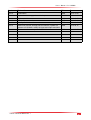
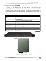
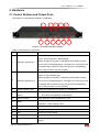
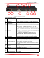
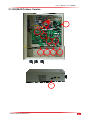
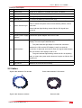
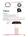
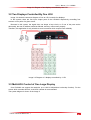
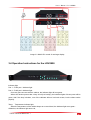
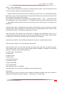
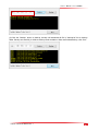
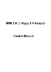
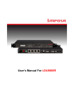
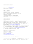
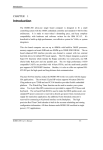
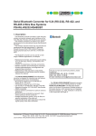
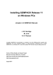
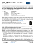
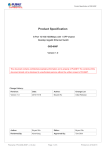
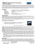
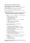
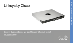
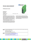
LDU2800
User’s Manual For LDU2800
User’s Manual For LDU2800
Contents
1. Introduction of LDU2800...................................................................................................................................... 4
2. Hardware................................................................................................................................................................ 5
2.1 Control Buttons and Output Ports............................................................................................................ 5
2.2 Cables........................................................................................................................................................... 8
3. Application.............................................................................................................................................................. 9
3.1 One Display Controlled By One LDU...................................................................................................... 9
3.2 Four Displays Controlled By One LDU................................................................................................. 10
3.3 Multi-LDU Control of One Large Display.............................................................................................. 10
3.4 Operation Instructions for the LDU2800............................................................................................... 11
4 Upgrade and backup CPU Programs of LDU2800........................................................................................ 13
4.1
Upgrade................................................................................................................................................... 13
4.2
Backup..................................................................................................................................................... 13
File NO. WI/CZ-PM-M0008 Ver1.1
2
User’s Manual For LDU2800
Version
Revised Content
Editor
Date
Ver1.0
First Edition
KIMI
2013-11-06
Ver1.1
Update hardware upgrade and back up
KIMI
2013-11-15
Ver1.2
Update details
KIMI
2013-10-25
Ver1.3
Add cabinet connection
KIMI
2013-12-31
Ver1.4
Modify LDU2800 version
KIMI
2014-02-19
Ver1.5
Add on/off function and light sensor interface, update the
pictures of LDU2800, modify the input and output resolution
KIMI
2014-08-15
Ver1.6
Add the interface description of LDU2800 outdoor version
KIMI
2014-09-17
File NO. WI/CZ-PM-M0008 Ver1.1
3
User’s Manual For LDU2800
1. Introduction of LDU2800
LDU2800 is a new generation of our LED display controller. It can receive DVI signal
(1920x1200@60Hz). After processing the DVI data, the internal VLSI ( Very Large Scale
Integration Circuits ) of the LDU 2800 will send the processed data to the control board of
the LED display through two-way Gibabit Ethernet. Specification of LDU2800 is shown in
Table 1.
Table 1 specification of LDU2800
Item
specification
DVI signal
Input
Max.:1920x1200@60Hz
TWO RJ45 ports
Output
Each port can support up to 1920x300 pixels
Max. resolution
1920x600 pixels
Communication
USB/ Ethernet
input:100-240 VAC, 50-60 Hz
Power supply
Max. power consumption: 10W
Working Temperature
-20~60℃
Working humidity
0-95%
Dimension (LxWxD)
360x435x44.45 mm
Image 1-1 LDU2800 (Indoor Version)
Image 1-2 LDU2800 (Outdoor Version)
File NO. WI/CZ-PM-M0008 Ver1.1
4
User’s Manual For LDU2800
2. Hardware
2.1 Control Buttons and Output Ports
The image2-1 is the interface diagram of LDU2800
2
1
4
3
6
5
8
7
10
9
11
Image 2-1 LDU2800 Operation Diagram
Table 2: Description of Components
NO.
Name
Function
Prot 1: RJ45 port 1 indicator light
Prot 2: RJ45 RJ45 port 1 indicator light
1
Indicator Light Group 1
When the light turns green, it indicates that the data is coming
out from the corresponding port; if no light is on or the light is red,
it indicates that no data is coming out from the corresponding
port or the port does not work properly.
Temp: Temperature indicator light
Power: Power indicator light
2
When the light turns green, it indicates that the data is coming
Indicator Light Group 2
out from the corresponding port; if no light is on or the light is red,
it indicates that no data is coming out from the corresponding
port or the port does not work properly.
3
Status Indicator Light
When the LDU2800 works properly, it would be on.
Brightness Control
+: Turn up the brightness of the display
Switch
-: Turn down the brightness of the display
5
Semi-on Switch
Turn down the current brightness by 50%
6
Mode
7
Black
Display the completely back image
8
Freeze
Freeze the image
9
Test
Shows the testing image
10
Info
No function
11
F1
4
File NO. WI/CZ-PM-M0008 Ver1.1
OUT DOOR:outdoor display mode
IN DOOR:indoor display mode
Press the button for 5 seconds, the LDU2800 will automatically
restart.
5
User’s Manual For LDU2800
3
1
2
11
5
8
6
4
7
9
10
Image 2-2 Interface of LDU2800
Table 3 Description of Ports
Name
Function
1
Power Port
Provide 100-240AC power supply to LDU2800 though this port
2
Power Switch
NO.
Turn on or turn off the LDU power supply
Once the LDU is power on, the indicator light will be on.
Gigabit Etherent signal output port, which is used for connecting
the LED screen. The largest resolution can be 1920 x300.
If the amber light is normally on, it indicates that the LDU
and the screen keep in good connection; otherwise it means the
3-4
RJ45 port
connection is abnormal, which needs to check the signal line that
connecting the LDU and the screen.
If the green light is blinking, it indicates that LDU is
outputting the data; otherwise it means the system works
abnormally. Maybe there is no effective DVI signal being input.
5
Reset Button
Reset the IP address of LDU2800 and restart the LDU2800
6
DVI output
DVI loop out, which mainly applied in multi-LDU cascade
Once the red light is blinking, it indicates that the CPU inside
works properly, otherwise it means the system encounters a
7
System indicator light
serious problem, and it cannot work properly.
If the green light is blinking, it means that effective DVI signal is
accepted.
DVI signal input port.
8
DVI input
9
USB port
Not available at the moment
10
Ethernet port
For network control of the LDU2800 via the main internet access
PSU on/off interface
Control the on/off function of PSU/control the auto brightness of
/Light sensor interface
LED display
11
File NO. WI/CZ-PM-M0008 Ver1.1
Can support signal of up to 1920x1200@60Hz
6
User’s Manual For LDU2800
2.1 LDU2800 Outdoor Version
9
10
7
8
5
1
6
2
3
4
11
File NO. WI/CZ-PM-M0008 Ver1.1
7
User’s Manual For LDU2800
Interface Description
No.
Name
Function Description
1
Reset button
Reset the IP address of LDU2800 and restart LDU2800
2
DVI output
DVI loop output, to cascade multiple LDUs
3
DVI input
DVI signal input, Max 1920x1200@60Hz
4
Ethernet port
To control LDU2800 by internet (main port)
Red indicator light blinking means the CPU inside the LDU works
well, or means the system comes across serious problem, cannot
5
System indicator light
work well.
Green indicator light blinking means effective DVI signal input
comes in.
6
7
USB port
Read back IP address and status
Exterior power supply
Connect the power diagram from PDU to LDU
interface
Gigabit Ethernet signal output interface. To connect the LED
display. The max output 1920x300 dots.
The yellow indicator light keeps on means the connection
between the LDU and the LED display is well, or means the
8-9
RJ45 interface
connection is abnormal and need to check the signal cable between
the LDU and the LED display is well or not.
The green indicator light blinking means the LDU is outputting
data, or means the system works abnormal, maybe no effective DVI
signal input.
10
ON OFF control panel
Blank screen or off the LED display at a fixed time.
11
Light sensor
Measure the environment luminosity
2.2 Cables
Signal cable between LDU and tile
Signal cable between cabinets
File NO. WI/CZ-PM-M0008 Ver1.1
Power cable between PSU and tile
Network cable
8
User’s Manual For LDU2800
DVI cable
Power cable between cabinets and the LDU
3. Application
This chapter will introduce three commonly-used work modes of LDU.
3.1 One Display Controlled By One LDU
Image 3-1 shows the structure diagram of how a LDU control a display.
LDU receives the DVI signal from computer or VPU, and sends the processed data to the LED
screen after processing it.
Two random ports consist of a loop circuit in such application. In this case, if one of the ports works
abnormally, it won’t have an effect on the operation of the whole screen. This is of great significance on
some important occasions.
File NO. WI/CZ-PM-M0008 Ver1.1
9
User’s Manual For LDU2800
Image 3-1 Diagram of two displays controlled by one LDU
3.2 Two Displays Controlled By One LDU
Image 3-2 shows the structure diagram of how an LDU controls four displays.
In this system, there are four input /output ports of the LDU2800 respectively controlling four
screens or four parts of a giant screen.
Because in this system, the signal does not shape a loop circuit, so if one of the ports works
abnormally, the rest of cabinets would be affected, and they cannot work properly.
Therefore, this application is only suitable to some occasions which require lower reliability.
Image 3-2 Diagram of 4 displays controlled by 1 LDU
3.3 Multi-LDU Control of One Large Display
One LDU2800 can support the resolution up to 1920 X 680(without hot backup function). For the
screen which exceeds this limit, multi-LDU cascade is recommended.
The system diagram is shown in the image 5.
File NO. WI/CZ-PM-M0008 Ver1.1
10
User’s Manual For LDU2800
Image 3-3 Multi-LDU control of one large display
3.4 Operation Instructions for the LDU2800
Indicator light
Prot 1:RJ45 port 1 indicator light
Prot 2:RJ45 port 2 indicator light
Once any port connects with the cabinet, the indicator light will turn green.
When two random ports make a loop circuit (hot backup), the indicator lights of these ports will be
green; And if the loop is broken, one of the cabinets will turn into back screen, but the others works
properly.
Temp: Temperature indicator light
When the temperature of the cabinet keeps at a normal level, the indicator light turns green。
Otherwise, the indicator light turns red,
File NO. WI/CZ-PM-M0008 Ver1.1
11
User’s Manual For LDU2800
Power: Power indicator light
When the power supply works properly, the indicator light turns green, and no information is found
on the LCD panel; otherwise, the indicator light turns red.
When the external network connects with the Ethernet port/ Artnet port, the corresponding indicator
light will turn green. If the external network connects with the Ethernet port and Artnet port at the same
time, both the indicator lights will turn green.
The brightness of the screen can be adjusted by pressing the button “+” and “-“. That means, if the
current brightness is 50%, press the button “+”, the brightness will be increased; while press the button
“-“, the brightness will be reduced. Each time you press the button, there will be a 5% change in the
brightness.
Press the button “HALF”, the brightness of the screen will be reduced by 50% no matter it is in outdoor
working mode or indoor working mode. That means, when the current brightness of the screen is 40%,
press the button “HALF”, the brightness will reduce to only 20%。
Press the button “OUT DOOR” and “IN DOOR”, the display will automatically switch over to
corresponding working mode, that means, there are two displaying mode, the outdoor and the indoor,
the brightness of the screen will change when the working mode is changed。
Press the button “BACK”, the LDU2800 will change the screen into a completely black image,
Press the button “Freeze”, the current interface will be frozen;
Press the button “Test”, the LDU 2800 will enter the testing mode, each time you press the button,
various testing mode can be chosen, 8 kind of testing signals is available in LDU2800,; then press the
button for 5 seconds, it will exit the testing mode.
For white screen, red green blue
For red screen,
For green screen,
For blue screen,
For horizontal scanning,
For vertical sacnning,
For grey level testing,
For TV signal testing,
Press the button “Info”, not available
Press the button “F1” for 5 seconds, LDU2800 can automatically restart,
Reset button
Press the button “reset” on the back of the LDU2800, LDU2800 will restart, then the IP address of
Ethernet port will restore the factory settings. (Ethernet port:169.254.10.49)
File NO. WI/CZ-PM-M0008 Ver1.1
12
User’s Manual For LDU2800
4 Upgrade and backup CPU Programs of LDU2800
4.1 Upgrade
(1).Open firmware LetNetTools.exe.
(2) Input the LDU2800 IP address.
(3).Click the “Update” button to Update. If successfully, it will show “UPDATE SUCCESSFULLY”.
When we finished, click “Exit”.
4.2 Backup
(1).Open firmware LetNetTools.exe
(2). Input the LDU2800 IP address.
File NO. WI/CZ-PM-M0008 Ver1.1
13
User’s Manual For LDU2800
(3).Click the “Backup” button to backup. backup will download all file in "backup.lst" list to backup
folder .Backup successfully, it will show backup result as bellow. When we finished backup, click “Exit”.
File NO. WI/CZ-PM-M0008 Ver1.1
14