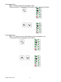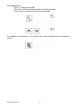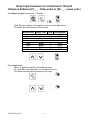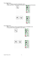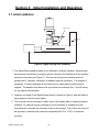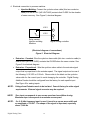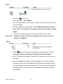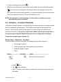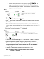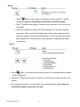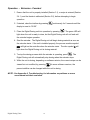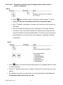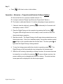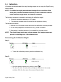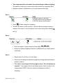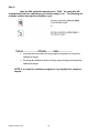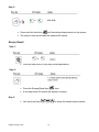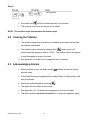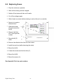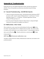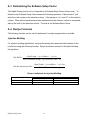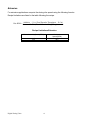
1
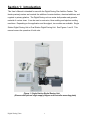
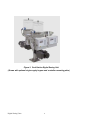
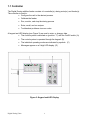
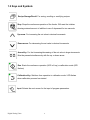
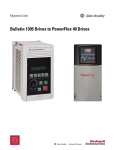
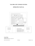
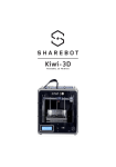
SDD Series Digital Dosing Additive Feeders Part Number: 882.00276.00 Bulletin Number: BF3-600.2 Effective: 11/01/06 Write Down Your Serial Numbers Here For Future Reference: _________________________ _________________________ _________________________ _________________________ _________________________ _________________________ We are committed to a continuing program of product improvement. Specifications, appearance, and dimensions described in this manual are subject to change without notice. DCN No. ____________ © Copyright 2006 All rights reserved. Table of Contents SECTION 1: INTRODUCTION …………….……………………….……….........................3 1.1 C150 Controller... .................................................................................... .5 1.2 Keys and Symbols ................................................................................... 6 SECTION 2: QUICK START-UP……………………………………...…….........................8 BASIC INPUT PARAMETERS – INJECTION MOLDING...……...……...12 BASIC INPUT PARAMETERS – EXTRUSION...................……...……...16 SECTION 3: INITIAL INSTALLATION AND OPERATION ............................…………20 3.1 3.2 3.3 3.4 3.5 3.6 Initial Installation ..................................................................................... 20 Initial Operation ...................................................................................... 23 Injection Molding..................................................................................... 24 Extrusion - Constant ............................................................................... 29 Extrusion - Proportional (Extruder tracking, or follower) ......................... 34 Calibration .............................................................................................. 38 SECTION 4: ADVANCED OPERATIONS/CONTROL FUNCTIONS.…....................…41 4.1 4.2 4.3 4.4 Recipe Storage/Recall ............................................................................ 41 Clearing the Totalizer ............................................................................. 43 Acknowledging Alarms ........................................................................... 43 Optional Equipment ................................................................................ 44 SECTION 5: MAINTENANCE……………...……………………………..…......................46 5.1 5.2 5.3 5.4 5.5 5.6 5.7 5.8 Maintenance Intervals ............................................................................ 46 Removing the Shear Plate (DD feeder only)........................................... 46 Cleaning the “DD” Dosing Station........................................................... 47 Changing the Dosing Disc in the “DT” Dosing Station ............................ 49 Removing/Replacing the Wiper in the “DT” Dosing Station .................... 50 Cleaning the “DT” Dosing Station ........................................................... 49 Exchangeable Stations ........................................................................... 52 Changing Fuses ..................................................................................... 53 APPENDIX A: TROUBLESHOOTING………………...................…………...………..…54 A.1 A.2 A.3 A.4 General Troubleshooting........................................................................ 54 Malfunctions — Error Codes .................................................................. 54 Determining the Software Setup Factor ................................................. 56 Recipe Formulas .................................................................................... 56 APPENDIX B: BASIC PARAMETER SETTINGS………………...................………..…58 APPENDIX C: DISC DOSING FACTORS, DRAWINGS AND PARTS NUMBERS......63 APPENDIX D: SPARE PARTS LIST…...………………………………....................……76 APPENDIX E: Technical Assistance...…..…………………………….......................…79 Digital Dosing Units 2 Section 1: Introduction This User’s Manual is intended for use with the Digital Dosing Disc Additive Feeder. The feeder precisely meters and controls the addition of master batches, chemical additives, and regrinds to primary plastics. The Digital Dosing unit can meter both powder and granular material of various sizes. It can be used on extrusion, blow molding and injection molding machines. Depending on the application and throughput, two models are available: Single Station Digital Dosing Unit or Dual Station Digital Dosing Unit. See Figures 1 and 2. This manual covers the operation of both units. Q U I C K S T A R T P A G E S H A V E B L U E Figure 1. Single Station Digital Dosing Unit (Shown with optional virgin supply hopper and controller mounting plate) Digital Dosing Units 3 B O R D E R Figure 2. Dual Station Digital Dosing Unit (Shown with optional virgin supply hopper and controller mounting plate) Digital Dosing Units 4 1.1 Controller The Digital Dosing additive feeder consists of a controller(s), dosing motor(s), and feeder(s). The controller is used to: • Configure the unit to the desired process. • Calibrate the feeder • Run, monitor, and stop the dosing process • Enter, recall, and run recipes • Troubleshoot problems via error codes A keypad and LED display (see Figure 3) are used to enter, or change, data. • The control system is switched on (position “1") with the On/Off switch. (A) • The control system is operated through the keypad. (B) • The individual operating modes are indicated by symbols. (C) • Messages appear on a 5-digit LED display. (D) Figure 3. Keypad and LED Display Digital Dosing Units 5 1.2 Keys and Symbols Recipe Storage/Recall: For saving, recalling or modifying recipes. Stop: Stops the continuous operation of the feeder. Will reset the totalizer showing metered amount of additive to zero if depressed for two seconds. Up-arrow: For increasing the set value in decimal increments. Down-arrow: For decreasing the set value in decimal increments. Arrow Key: For fast increasing/decreasing of the set value in larger increments. Must be pressed simultaneously with the up- or down-arrow. Run: Starts the continuous operation (LED is lit up) or calibration mode (LED flashes) Calibration Key: Switches from operation to calibration mode. LED flashes when calibration process has started. Input: Selects the next screen for the input of program parameters. Digital Dosing Units 6 Symbols Lights when the run signal from the process machine is received by the Digital Dosing controller. During operation, lights when the disc is dosing material. During calibration and recipe input/viewing, lights when a calibration weight is input or viewed. (EXTRUSION ONLY) Lights when a screw speed signal is received from the extruder during proportional extrusion control (tracking, or following) Lights when an alarm occurs. Percent additive Kilograms Grams Pounds Minutes Seconds Digital Dosing Units 7 Section 2: Quick Start-up Quick Start is intended to help you in starting up your Digital Dosing feeder quickly and easily. Please refer to the manual to go into greater detail. Unpacking: 1. Unpack box, making sure all parts indicated on packing list are included. 2. Check all parts and equipment for any damage sustained during shipment. 3. If any damage is noted, contact manufacturer for replacement or service. 4. Make sure the following are present before proceeding: ; Power source 110 or 220 volt, single phase, 50 or 60 hertz (verify voltage on Serial Number tag ; Proper mounting flange adapter for the feed throat ; Dry (ZERO VOLTAGE) contact that closes during screw recovery of IMM ; Gram scale to measure weight of additive material for calibration. Mounting: 1. Mount the complete unit, including dosing hopper full of material, on the feed throat (may need an adapter for feed throat). 2. Identify the motor drive connector (“Amp” connector-black) and connect to motor. 3. Identify the communication cable (DB-9 plug-silver) and connect to DB-9 connector under motor drive assembly. 4. Identify power cord and plug into appropriate outlet. 5. INJECTION MOLDING: Identify the cycle/run cable (2-conductor cable-gray) for connection to a dry (ZERO VOLTAGE) contact that closes during the screw recovery cycle of the molding machine. 6. EXTRUSION: Identify the input cable (2-conductor cable-gray) for connection to 0-10 VDC or 0-20 mA signal that indicates speed (rpm) of the extruder. Digital Dosing Units 8 Recipe Setup for Injection Molding: 1. Turn power switch to ON position. 2. Press Input to display # 1, “Additive %”. Using arrow keys, set additive ratio. 3. Press Input to display #2, “Shot size of current mold”. Using arrow keys, set the total shot size (parts and runners) of the current mold capacity in grams/pounds. 4. Press Input to display # 3, “Screw recovery time”. Using arrow keys, set the screw recovery time (in seconds). 5. Press Input to display # 4, “Calibration weight for additive”. Enter the appropriate value from the range table below and proceed to calibration mode below for calibration of additive material. DD Discs Disc Calibration Number Range DD 30-030672 1.75 DD 30-051040 5.00 DD 30-051725 8.00 DD 30-051818 15.00 DT Discs Disc Calibration Number Range DT 30-101820 32.00 DT 30-102025 38.00 DT 30-203012 100.00 DT 30-204010 175.00 Digital Dosing Units DP Discs Disc Calibration Number Range DP 30-050940 17.00 DP 30-250940 8.00 9 Recipe Setup for Extrusion: 1. Turn power switch to ON position. 2. Press Input to display # 1, “Additive %”. Using arrow keys, set additive ratio. 3. Press Input to display # 2, “Throughput of extruder”. Using arrow keys, set the total extruder throughput in g/min or lb/min. 4. Press Input to display # 3, “Extruder screw speed”. Using arrow keys, set the extruder screw speed RPM expected during production. NOTE: For Extrusion - Constant operation, the above step will be skipped. 5. Press Input to display # 4, “Calibration weight for additive”. Enter the appropriate value from the range table on page 9 and proceed to calibration mode below for calibration of additive material. Calibration: 1. Press “Calibration” button to start this procedure. Display will show - - - - 2. Place the plastic calibration cup on the scale and tare so that the weight of the cup (approx. 24 grams) is not calculated in the calibration procedure. 3. Remove cover of the calibration box, secured by two 5 mm Allen screws, under the dosing disc assembly and insert plastic cup provided in top of dosing hopper. 4. Press “Run” and the dosing disc turns 1/4 turn. This fills all pockets of dosing disc. Dump the dosed material back into the dosing hopper without weighing and replace plastic cup in calibration box. 5. Press “Run” and the dosing disc turns 1 complete revolution. Remove the calibration cup with the material and place on the gram scale. Enter the weight on the scale into the controller using the arrow keys. Empty and replace calibration cup. 6. Repeat step # 5 four more times, each time entering the new weight from the scale into the controller using the arrow keys. Sometimes the values won’t change, or sometimes they may only change by a few tenths of a gram. The controller keeps a running average of all calibration weights entered. Digital Dosing Units 10 7. After all five samples have been completed; press “run” once more and this will save the calibration weight of the material to the recipe. The calibration light will go out and the screen will now show the total amount of additive dosed. The Digital Dosing feeder is now ready to begin operation. 8. Please refer to “Operation Manual” for all supplementary information regarding general operation, cleaning/maintenance, and troubleshooting. 9. Make sure that there is a virgin material supply setup to begin processing. If you do not have a loader or hopper for the virgin material, or if any of the above procedures did not work properly, please contact ACS Technical Support @ (800) 423-3183 (8 AM - 5 PM) CST. Digital Dosing Units 11 Basic Input Parameters for Digital Dosing Feeder with Injection Software (P1._ _ - Older units) or (P2._ _ - newer units) Hold Stop and Input buttons until “7” flashes - Enter the input number for the specific motor from the table below. - This value sets the impulses of the encoder. Manufacturer Bauer Bauer Bauer Bison Bison Bison Bison Motor Color Blue Blue Blue Black Black Black Black RPM 6.4 11.5 35.5 2 6 12 38 Input Number 11739 6600 2135 65000 25200 14103 4387 Press Input button - When “8” flashes, enter 0.7 for Blue Bauer motor. - Or, enter 0.5 for the black Bison or Colorblend S motor. - This value sets the nominal current for the motor. Digital Dosing Units 12 Press Input button -When “9” flashes, enter the configuration value. - Please see the list: “Determining Configuration Value” for more information. Press Input button - When “10” flashes, enter 1 if a blue Bauer motor is intended for use. - If any another motor is intended for use, enter 0. Digital Dosing Units 13 Press Input button - When “11” flashes, enter 50 - This value is the minimum input frequency. Press Input button − When “12” flashes, enter 5.56 − This value is the span factor. Press Input button − When “13” flashes, enter the communication address. − If Euromap17 is not intended to for use, enter 0. − This value is the communication address. Only enter a value here if Euromap17 report is in use. Digital Dosing Units 14 Press Input button − When “14” flashes, enter 220 − This value is for the material contents of the mixing hopper. − Only in case of mounting on a micro mixing-hopper. Press Stop to exit parameters, “18” will flash, then it automatically returns to the totalizer screen Digital Dosing Units 15 Basic Input Parameters for Colorblend C-150 with Extrusion Software (E1._ _ - Older units) or (E2._ _ - newer units) Hold Stop and Input buttons until “7” flashes - Enter the input number for the specific motor from the table below. - This value sets the impulses of the encoder. Manufacturer Bauer Bauer Bauer Motor Color Blue Blue Blue RPM 6.4 11.5 35.5 Input Number 11739 6600 2135 Bison Bison Bison Bison Black Black Black Black 2 6 12 38 65000 25200 14103 4387 Press Input button - When “8” flashes, enter 0.7 for blue Bauer motor. - Or, enter 0.5 for the black Bison or Colorblend S motor. - This value sets the nominal current for the motor. Digital Dosing Units 16 Press Input button - When “9” flashes, enter the configuration value. - Please see the list: “Determining Configuration Value” for more information. Press Input button - When “10” flashes, enter 1 if a blue Bauer motor is intended for use. - If any another motor is intended for use, enter 0. Digital Dosing Units 17 Press Input button - When “11” flashes, enter 50 - This value is the minimum input frequency. Press Input button − When “12” flashes, enter 10 − This value is the span factor. Press Input button − When “13” flashes, enter the communication address. − If Euromap17 is not intended to for use, enter 0. − This value is the communication address. Only enter a value here if Euromap17 report is in use. Digital Dosing Units 18 Press Input button - When “14” flashes, enter 220 - This value is for the material content of the mixing hopper. - Only in case of mounting on a micro mixing-hopper. Press Stop to exit parameters, “18” will flash, then it automatically returns to the totalizer screen. Digital Dosing Units 19 Section 3: Initial Installation and Operation 3.1 Initial Installation Hopper Piece Processing Machine Direction of Material Flow Figure 4. Digital Dosing Unit Assembly 1. The Digital Dosing additive feeder is not affected by machine vibration, therefore best performance is achieved by mounting the unit directly to the feed throat of the molding machine or extruder (see Figure 4). The inlet into the process machine must be greater than 2” diameter; otherwise, an adapter might be necessary. If an adapter is necessary, it must be designed so that there are no edges where material can be trapped. The adapter must be smooth to promote even material flow. Consult factory for any special requirements. 2. Optimum mounting of the Digital Dosing feeder is shown in Figure 4, with the additive being dosed on the first screw flights. 3. The controller can be mounted on either side of the blender base to optimize operator interface. An optional remote mounting kit for the controller is available from the manufacturer to relocate the controller closer to the operator. The control unit must not be exposed to extreme heat (maximum temperature 45°C or 115°F) or excessive moisture. Digital Dosing Units 20 4. Electrical connection to process machine: • Injection Molding: Connect the cycle/run slave cable (thin two-conductor cable) to a set of DRY (NO VOLTAGE) contacts that CLOSE for the duration of screw recovery. See Figure 5, electrical diagram. J12-3 J12-2 Relay contact Injection molding Machine Digital Dosing controller (Electrical diagram of connections) Figure 5. Electrical Diagram • Extrusion - Constant: Wire the cycle/run slave cable (thin two- conductor cable) to a set of DRY (NO VOLTAGE) contacts that CLOSE when the screw rotates. See Figure 5 for electrical diagram. • Extrusion - Proportional: Wire the cycle/run slave cable to the extruder signal output that is proportional to the extruder speed. The signal output can be one of the following: 0-10 VDC or 0-20 mA. Please refer to the labels on the cycle/run slave cable for the correct input to avoid damaging the controller. Digital Dosing Additive Feeder should be configured from the factory for each specific input. See Figure 6 for analog inputs. NOTE: Voltage from Extruder needs to be isolated. Consult factory for other signal requirements. External signal converter may be required. NOTE: Zero input corresponds to zero screw speed and no additive dosing. Maximum input corresponds to maximum screw speed. NOTE: If a 0-10 kHz frequency input is used, it must be a square wave width and an amplitude of 12 VDC. The shape of the signal is important, especially above 7,000 Hz. Digital Dosing Units 21 J12-4 _ J12-3 + 0-10 VDC or 0-20 mA Extruder output Digital Dosing controller (diagram of analog inputs) Figure 6. Analog Inputs 5. Make sure the unit is turned OFF before plugging it in. The switch toward the rear of the controller unit should be in the OFF, or “O” position. Standard operation voltage is 110 or 220 VAC, 50/60 Hz, single-phase power. Special voltages are available, refer to voltage label on the feeder to determine the correct operating voltage. Extruder Follower Interface Signal Converter Isolating power sources and sensor signals is the most effective method for eliminating undesirable ground loop currents and induced electrical noise. To determine the correct signal convert to use: o Define whether a current (mA) or voltage (dc) signal from the extruder is available to utilize. o The range should be either be 0-20 mA or 0-10 VDC, respectively. o The controller has no specific requirement other than the signal being isolated and proportional to the speed of the extruder. Signal Converter with AC Power Supply Vendor: Phoenix Contact Order Designation: MCR-FL-C-UI-UI-DCI-24/230 Supply Voltage: 20V to 253V AC/DC Input 4-20 mA, 0-10 VDC (Quantity: 1) Output 0-20 mA, 0-10 VDC (Quantity: 1) Digital Dosing Units 22 Signal Converter with DC Power Supply This module requires a separate 24 VDC power supply. Vendor: Phoenix Contact Order Designation: MCR-FL-C-UI-2UI-DCI-NC Supply Voltage: 20 to 30V DC Input 4-20 mA, 0-10V (Quantity: 1) Output 0-20 mA, 0-10V (Quantity: 2) 24 VDC Mini Power Supply A Phoenix Contact power supply for the Phoenix Contact signal conditioner listed above. Vendor: Phoenix Contact Order Designation: MINI-PS-100-240AC/24DC/1 Please note that the data given here has been taken from Phoenix Contact's online catalog. For comprehensive information and data, please refer to the user documentation at http://www.download.phoenixcontact.com. 3.2 Initial Operation The control system is factory-programmed. Nevertheless, specific values need to be predefined or checked prior to operation (basic parameter settings). The input values will be saved and will still be available if the unit is switched off, or a power failure occurs. Please refer to Appendix B for these values. Extrusion operations require a “span factor” to be entered into the basic settings. Please refer to Appendix B. Prior to putting your new Digital Dosing Additive Feeder on-line: • You must enter a recipe and calibrate the feeder. • Recipe parameters are different for Injection Molding, Extrusion - Constant, and Extrusion - Proportional operation. See each individual section for details. • The calibration method is the same for all processes. • Once the unit is online, recipes can be saved for later recall (10 maximum). Digital Dosing Units 23 • This section will show how to calibrate the unit, bring the unit on line, enter a recipe, and store and recall recipes. 3.3 Injection Molding During each molding cycle the Digital Dosing unit doses the correct amount of additive evenly throughout the screw recovery cycle. The Digital Dosing unit determines the correct amount of additive from the recipe and automatically adjusts the duration and speed of dosing by measuring the molding machine screw recovery time each cycle. Recipe Input - Injection Molding To enter a recipe for injection molding, the following process data is required: • Percentage of additive • Total shot weight in grams (includes parts and runner system) • Screw recovery time of the machine in seconds • Calibration weight in grams • Step 1: • Press Input • The LED symbol • “1” will quickly flash on the display, before a number in the format xxx.xx once. flashes. comes up on the display. • Enter the additive percentage by using the Arrow Keys . (The range of values that can be entered is 0.01% to 50.00%. The arrow keys are used to change all process variables. The double arrow key allows the user to ramp up or down by larger increments.) Digital Dosing Units 24 Step 2: • Press Input • The symbols “g,” or “lb”, “min” and the screw symbol flash. • After the “2”quickly flashes on the display, a number in the format xx.xxx will again. come up on the display. • Enter the shot weight using the arrow keys. The range of values that can be entered is 001.0 to 6500 grams (0.01 to 14.30 pounds). Step 3: “3” = screw recovery time in seconds • Press Input • The screw and “s” symbols flash. • After “3” flashes quickly on the display, a number in the format xxx.xx will come a third time. up on the display. • Enter the screw recovery time in seconds. This time represents the amount of time the molding machine screw is in recovery. This value is an estimate. The Digital Dosing unit measures the actual recovery time and automatically updates this value during operation. NOTE: The range of values that can be entered in this field is 2.00 to 99.99 seconds. Digital Dosing Units 25 Step 4: “ 4 “ = calibration weight in grams or pounds • • Press Input a fourth time. The symbols “g” or “lb”and flash. • After “4” quickly flashes on the screen, a number in the format xxxx.x will come up on the display. • Enter the calibration weight in grams. If the calibration weight is unknown, enter “valve” from (section 5.7 knowing you Disc size) to obtain a starting weight. • The range of values that can be entered in this field is 00.0 to 400.0. Please note: Parameters 5 and 6 will only be displayed when a mixer and or a printer is configured. Step 5: • Press again and the symbol “s” will light up and the number “5” will be displayed if you have a blending unit and have invoked this option. • After “5” flashes on the display, a number in the format xxx.xx will come up on the display. • Enter the maintained running time of the blending unit in seconds using the arrow keys. This is how long the blender will run after each dosing cycle and should be adjusted for the best possible blend. Too little time may not produce good dispersion; too much time can cause separation, especially with heavy concentrates. Digital Dosing Units 26 Step 6: • Pressing • After the “6” flashes on the screen, a number in the format xxx.xx will come up again, will activate the printing option if it is available. on the display. • By using the arrow keys, you can choose your printer parameters. Step 7: 1. Pressing again will first display the number “18” and then will display the total throughput in kilograms (totalizer). Digital Dosing Units 27 Operation - Injection Molding 1. Ensure that the unit is properly installed (Section 3.1), a recipe is entered (section 3.3.1), and the feeder is calibrated (Section 3.6), before attempting to begin operation. 2. If desired, clear the totalizer by holding the Stop key ( ) continuously for five seconds until the display is reset to “00.00.” 3. Place the Digital Dosing feeder into operation by pressing the Run key ( ). The green LED will light when the unit is ready to dose. or Start the molding machine. The Digital Dosing feeder will not dose material until the molding machine screw recovers. If the unit is installed properly, the process machine symbol will light on the controller during screw recovery. The disc symbol will light when the Digital Dosing unit is dosing material. • The totalizer will increase after each cycle by the amount of material dosed. Digital Dosing Units 28 • To stop the dosing process, press • While the unit is dosing, the current recipe can be viewed, but not modified by pressing . . The recovery time displayed in the current recipe is the average of the last five shots measured from the molding machine. To change the recipe, the unit must be taken off line by pressing the stop key. The run LED will then go out. NOTE: See Appendix A, Troubleshooting, for information on problems or errors encountered and their resolution. 3.4 Extrusion – Constant (Standard) In Extrusion Constant operation, the Digital Dosing unit doses material at a constant rate that does not change with extruder speed. The dosing process begins at the startup of the extruder. How close the actual extruder speed is to the input recipe will determine the accuracy of the blend. If the process requires the additive to be dosed in proportion to the process speed, then the Digital Dosing unit must be configured for Extrusion Proportional operation (go to Section 3.5). Recipe Input – Extrusion - Constant To enter a recipe for Extrusion Constant, the following process data is required: • Percentage of additive • Total throughput rate of the extruder during production • Calibration weight in grams • Step 1: • Press • The • After “1” flashes on the screen, a number in the format xxx.xx will come up on once. symbol will flash. the display. Digital Dosing Units 29 • Enter the additive percentage by using the Arrow Keys . The range of values that can be entered is 0.01 to 50.00%. The arrow keys are used to change all process variables. The double arrow key allows the user to ramp up or down at a faster rate. Step 2: or • • Press again. The symbols “g,” or “lb”, “min”, and • After “2” flashes quickly on the display, a number in the format xxx.xx will come up on flash. the display. • Enter the total extruder throughput in grams per minute or pounds per minute. The range of values that can be entered is 001.0 to 6500 grams per minute (00.01 to 14.30 lb/m). Extrusion Constant, parameter “3” is skipped. Step 3: “ 4 “ = calibration weight in grams or pounds • Press • The machine displays a flashing • After the “4” flashes on the display, a number in the format xxxx.x will come up. • Enter the calibration weight in grams. If the calibration weight is unknown, enter a third time. , “g” or “lb” and a number “4”flashes on the display the appropriate “value” from Section 2, based on your disc size, to obtain a starting weight. • The range of values that can be entered in this field is 00.00 to 400.0. Note: Parameters 5 and 6 will only be displayed when a mixer and or a printer is configured. Digital Dosing Units 30 Step 4: • Press again and the symbol “s” will light up and the number “5” will be displayed if you have a blending unit and have invoked this option. • After “5” flashes on the display, a number in the format xxx.xx will come up on the display. • Enter the maintained running time of the blending unit in seconds using the arrow keys. This is how long the blender will run after each dosing cycle and should be adjusted for the best possible blend. Too little time may not produce good dispersion; too much time can cause separation, especially with heavy concentrates. Step 5: • Press again. This will activate the printing option if it is available and the number “6” will be displayed. • After the “6” flashes on the screen, a number in the format xxx.xx will come up on the display. • By using the arrow keys, you can choose your printer parameters. If you have not activated this option, skip to the next step. Digital Dosing Units 31 Step 6: 6. Press again. 7. The number “18” will be displayed before the total throughput in kg is displayed. Digital Dosing Units 32 Operation – Extrusion - Constant 1. Ensure that the unit is properly installed (Section 3.1), a recipe is entered (Section 3.4.1), and the feeder is calibrated (Section 3.6), before attempting to begin operation. 2. If desired, clear the totalizer by pressing continuously for 5 seconds until the display is reset to “00.00.” 3. Place the Digital Dosing unit into operation by pressing . The green LED will light when the unit is ready to dose, but the Digital Dosing unit will not feed until the extruder begins operation. 4. Start the extruder. The Digital Dosing unit will begin dosing material as soon as the extruder starts. If the unit is installed properly, the process machine symbol will light on the controller when the extruder starts. The disc symbol will light when the Digital Dosing unit is dosing material. 5. To stop the dosing process while the extruder is operating, press . The Digital Dosing unit will automatically stop dosing when the extruder stops. 6. While the unit is dosing, depending on software revision, the current recipe can be viewed but not modified, by pressing . In some software versions, the percent additive can be changed while the unit is dosing. NOTE: See Appendix A, Troubleshooting, for information on problems or errors encountered and their resolution. Digital Dosing Units 33 3.5 Extrusion – Proportional (Extruder Follower Option) Recipe Input – Extrusion Proportional To enter a recipe for Extrusion Proportional, the following process data is required: • Percentage of additive • Expected throughput of the extruder during production • Extruder screw speed during production • Calibration weight in grams Step 1: • Press the Input key, • The • After “1” flashes quickly on the display, a number in the format xxx.xx will come , once. symbol flashes. up on the display. • Enter the additive percentage by using the Arrow Keys . The range of values that can be entered is 0.01% to 50.00%. The arrow keys are used to change all process variables. The double arrow key allows the user to ramp up or down at a faster rate. Step 2: or • Press • The machine displays a flashing “g” or “lb”, a flashing “min” and Digital Dosing Units again. 34 . • After “2” flashes quickly on the display, a number in the format xxx.xx will come up on the display. • Enter the expected extruder throughput during production in grams per minute or pounds per minute. The range of values that can be entered is 001.0 to 6500 grams per minute (00.01 to 14.30 lb/m). Step 3: • Press • The machine displays a flashing screw • After “3” flashes quickly on the display, a number in the format xxx.xx will come a third time. . up on the display. • Enter the extruder screw speed (rpm) corresponding to the throughput entered in step 2. Step 4: “ 4 “ = calibration weight in grams or pounds • Press • The machine displays a flashing • After “4” flashes quickly on the screen, a number in the format xxx.xx will come up a fourth time. and “g”. on the display. • Enter the calibration weight in grams. If the calibration weight is unknown, enter the appropriate “value” from Section 2, based on your disc size, to obtain a starting weight. • Upon completion of the calibration procedure, the calibration weight will automatically be updated into the recipe. The range of values that can be entered in this field is 00.00 to 400.0. Digital Dosing Units 35 Please note: Parameters 5 and 6 will only be displayed when a mixer and or a printer is configured. Step 5: • Press again and the symbol “s” will light up and the number “5” will be displayed if you have a blending unit and have invoked this option. • After “5” flashes on the display, a number in the format xxx.xx will come up on the display. • Enter the maintained running time of the blending unit in seconds using the arrow keys. This is how long the blender will run after each dosing cycle and should be adjusted for the best possible blend. Too little time may not produce good dispersion; too much time can cause separation, especially with heavy concentrates. Step 6: • Press again. This will activate the printing option if it is available and the number “6” will be displayed. • After the “6” flashes on the screen, a number in the format xxx.xx will come up on the display. • By using the arrow keys, you can choose your printer parameters. If you have not activated this option, skip to the next step. Digital Dosing Units 36 Step 7: • Press a fifth time to return to the totalizer. Operation – Extrusion – Proportional (Extruder Follower Option) ; Ensure that the unit is properly installed (Section 3.1) ; A recipe is entered (“Recipe Input-Extrusion Proportional” Section ) ; The feeder is calibrated (Section 3.6), before attempting to begin operations. 1. If desired, clear the totalizer by pressing continuously for 5 seconds until the display is reset to “00.00.” 2. Place the Digital Dosing unit into operation by pressing the Run key ( ). The green LED will light when the unit is ready to dose, but will not feed until the extruder begins operation. 3. Start the extruder. The Digital Dosing unit will begin dosing material as soon as the extruder starts. If the unit is installed properly, the process machine symbol will light on the controller when the extruder starts. The disc symbol will light when the Digital Dosing is dosing material 4. To stop the dosing process while the extruder is operating, press . The Digital Dosing unit will automatically stop dosing when the extruder stops. 5. While the unit is dosing, depending on software revision, the current recipe can be viewed but not modified, by pressing . In some software versions, the percent additive can be changed while the unit is dosing. The actual extruder screw speed will be displayed in the third recipe register. Digital Dosing Units 37 3.6 Calibration All feeders must be calibrated before any blending recipes can run using the Digital Dosing additive feeder. NOTE: The calibration weight (metered material weight for one revolution of the dosing disc) must be determined separately for each material to be dosed since calibration weight differs from material to material. The following equipment is needed for calculating the calibration weight: • Scale with a minimum accuracy of 0.01 grams • The weighing container which is included in the equipment delivery Follow these procedures: 1. Remove one of the square covers and insert the calibration container provided. 2. Fill the dosing hopper with a minimum of six (6) inches of material. 3. Note weight of weighing container (= tare weight) or tare scale to zero NOTE: The Digital Dosing station may only be operated if all sample chutes are in place or a collecting bin is in the calibration box. Determining the Calibration Weight Step 1: • To start the calibration process, press the calibration key. • • . Once the sample container is in position, press The disc will rotate 1/4 revolution and dispense material into the sample Step 2: container. After the disc stops, the screen will remain blank. Digital Dosing Units 38 • This sample should be returned to the material hopper without weighing. This sample is used only to ensure that all disc pockets are completely filled. • Replace container in calibration box (or under material outlet tube) • Press • The disc will rotate one full revolution. After the disc has stopped rotating, a Step 3: to take a sample for weighing. number in the format “xx.xx” will appear on the screen along with a flashing and “g.” Step 4: • Enter the weight, in grams using the Arrow Keys • Empty and replace weighing container in calibration box (or under material outlet tube) Step 5: • Repeat steps 3 and 4 four (4) more times. • Notice that the displayed calibration weight may change after each sample weight is entered. • The value is an average of all the weights entered. No calculations are required. It can happen that the calculated speed is either too high or low causing alarm A0009. Check the recipe and settings and modify if necessary. Digital Dosing Units 39 Step 6: After the fifth calibration sample press “ RUN “ the controller will automatically finish the calibration cycle and be ready to run. The following are methods used to interrupt the calibration cycle. • Pressing the stop button will stop proportioning and not accept the calibration weight. • Pressing the calibration button will stop proportioning and accept the calibration weight. NOTE: It is normal for calibration weights to vary slightly from sample to sample. Digital Dosing Units 40 Section 4: Advanced Operations/ Control Functions 4.1 Recipe Storage and Recall A maximum of ten (10) recipes can be stored and retrieved with the Digital Dosing controller in the Recipe Storage/Recall mode. Recipes are stored using a two-digit identification number. Pressing at any time will exit the Recipe Storage/Recall mode. Recipe Storage To store the current recipe: Step 1: • ). A two-digit number (01 through 10) will Press the Recipe Storage/Recall key ( appear on the screen. This is the recipe I.D. number. Step 2: • Use the Arrow keys to select the desired recipe number. NOTE: A new recipe stored under the ID number of an existing recipe will overwrite the existing recipe number without warning. Digital Dosing Units 41 Step 3: or • Press and hold the button • The recipe is now stored under the selected ID number. until the totalizer display returns to the screen. Recipe Recall Step 1: or • Press the stop button to stop any current applications. • Press the Storage/Recall key ( • A two-digit recipe ID number will appear on screen. • Use the Arrow Keys Step 2: ) once. Step 3: Digital Dosing Units to select the desired recipe number. 42 Step 4: • Press and hold • The recipe is now active and can be run or edited. until the totalizer appears on the screen. NOTE: The recalled recipe now becomes the active recipe. 4.2 Clearing the Totalizer • The totalizer displays the total amount of additive dosed since the last time the totalizer was cleared. • The totalizer can be cleared by pressing Stop continuously for 5 seconds until the display is reset to “00.00.” The totalizer can be configured to read throughput in grams or pounds. • See Appendix A to learn how to change the unit of measure. 4.3 Acknowledging Alarms • When an alarm occurs, the Alarm symbol flashes red and the dosing process stops. • If the Digital Dosing is equipped with an audible alarm or flashing light, it will also be activated. • Alarms are acknowledged by pressing • The alarm will also initiate an error code. • See Appendix A for Troubleshooting suggestions for various alarms. • The alarm condition must be corrected prior to beginning operation again. Digital Dosing Units 43 . 4.4 Optional Equipment, Level Switches and Communications Options Optional equipment for the Digital Dosing Additive Feeder includes: Alarms Several alarm options are available for the Digital Dosing feeder. The standard unit comes with a flashing alarm symbol on the faceplate. Options include both audible horns and flashing lights. An optional no voltage alarm relay can be connected to the user’s central alarm system. Level switches (probes) To adjust the level switches: 1. Turn the controller ON. 2. Fill the dosing station until the level sensor is one-third covered. 3. Remove the small plastic screw (M3) on the back of the level sensor (see Figure 7). LED Yellow (Station) on: Station Filled off: Station Emptied LED Green (Level Probe) on: Power Supply Available off: Power Supply Not Available npn: Normally Closed pnp: Normally Open 1 npn: Normally Open 0 pnp: Normally Closed Blind Lid Trim-pot with Plastic Screw M3 Protective Screw Cable Level Probe Figure 7. Level Sensor Screw 4. Turn the trim-pot until the yellow control lamp just switches off. Digital Dosing Units 44 NOTE: Turning the trim-pot to the left decreases the switching sensitivity; turning it to the right increases the switching sensitivity. 5. Fill the dosing station until the level probe is two-thirds covered. The yellow control lamp should now switch on again. If not, repeat Step 4. 6. Reinstall the plastic screw (M3). NOTE: The sliding switch under the cover must be set on “0”. Communication Protocol Interfaces The Digital Dosing unit can be controlled remotely through the EUROMAP E17 or MODBUS RTU protocol. Contact Sales and Service concerning this option at 810.720.7300. Digital Dosing Units 45 Section 5: Maintenance 5.1 Maintenance Intervals Check warning signs on equipment for good legibility Daily: and completeness. Weekly: Check function of the “On/Off” Switch. Check shear plate in “DD” dosing station, and wiper in Every 3 months: “DT” dosing station. Check that all electrical and mechanical connections Every 6 months: are tight. Annually: Check dosing disc in dosing station DD/DT. Each time after material Is changed: Clean the dosing station. Check adjustment of the level probes (optional). Check shear plate or wiper. Check dosing disc. 5.2 Removing the Shear plate (DD feeder only) Removing the shear plate 1. Empty the dosing Figure station. 2. Open the profile clamp (B) on the dosing hopper. 3. Remove the dosing hopper from the dosing unit. 4. Open the safety screws at the toggle-type fasteners. 5. Open the toggle-type fasteners on the dosing motor. Digital Dosing Units 46 6. Remove the dosing unit from the dosing motor. 7. Remove the cover from the connecting piece (D). 8. Loosen the two screws (C) on the underside of the dosing unit housing (E). 9. Remove the shear plate (A). Installing the shear plate 1. Place the new shear plate in the dosing unit housing. 2. Ensure that the shear plate is positioned correctly. 3. Screw the shear plate in place by means of 2 hexagon socket screws (M5 x 16). 4. Turn the dosing disc to check for smooth movement. 5. Mount the cover on the connecting piece. 6. Position the dosing unit on the dosing motor (note guide pins). 7. Close the toggle-type fasteners on the dosing motor. 8. Mount the safety screws. 9. Position the dosing hopper on the dosing unit. 10. Mount the profile clamp. 11. Mount the screw at the profile clamp. 5.3 Cleaning the “DD” Digital Dosing Station Dismantling the Dosing Station 1. Empty the dosing station. 2. Switch the control unit off by means of the on/off switch. 3. Disconnect from main voltage. 4. Open the profile clamp on the dosing hopper. Digital Dosing Units 47 5. Remove the dosing hopper from the dosing unit. 6. Dismantle the dosing unit and remove the shear plate (D). 7. Loosen the two hexagon socket screws (B, M6 x 30) on the top side of the dosing disc (A). 8. Loosen the center hexagon socket screw (C, M6 x 12) and replace by an M6 x 60 screw. 9. Lift the dosing disc (A) from the dosing unit housing (B) by this screw. 10. Clean the shear plate using a cotton cloth. 11. Clean the dosing hopper and the dosing disc in soapy water. 12. The dosing unit housing may also be cleaned with soapy water. 13. Ensure that soapy water does not enter ball bearings. 14. Dry all parts thoroughly. Installing the Dosing Station 1. Place the dosing disc in the dosing unit housing. 2. Remove the screw (M6 x 60). 3. Screw the dosing disc in place by means of 2 hexagon socket screws (M6 x 30). 4. Mount the center hexagon screw (M6 x 12). 5. Install the shear plate and then the dosing unit. 6. Turn the dosing disc to check for smooth movement. 7. Position the dosing hopper on the dosing unit. 8. Tighten the profile clamp. Digital Dosing Units 48 5.4 Changing the Dosing Disc in the “DT” Digital Dosing Station Removing the Dosing Disc 1. Empty the dosing station. 2. Switch the control unit off by means of the on/off switch. 3. Dismantle the dosing unit and remove the shear plate. 4. Loosen the two hexagon socket screws (M6 x 30) on the top side of the dosing disc. 5. Loosen the center hexagon socket screw (M6 x 12) and replace by a M6 x 60 screw. 6. Lift the dosing disc from the dosing unit housing by this screw. Installing the Dosing Disc 1. Change and place the dosing disc in the dosing unit housing. 2. Remove the screw (M6 x 60). 3. Screw the dosing disc in place by means of 2 hexagon socket screws (M6 x 30). 4. Mount the center hexagon socket screw (M6 x 12). 5. Install the shear plate and then the dosing unit. 6. Turn the dosing disc to check for smooth movement. 7. Position the dosing hopper on the dosing unit. 8. Tighten the profile clamp. See Appendix D: Spare Parts List on page 61 for disc part numbers. Digital Dosing Units 49 Installing Different Types of Dosing Discs Dosing discs of the same type, and thickness (72 pocket), may be exchanged for each other without any problems. If dosing discs with a different compartment number or thickness are installed, this has to be entered in the control system! DD Discs Disc Calibration Number of Number pockets DD 30-030672 1.75 72 DD 30-051040 5.00 40 DD 30-051725 8.00 25 DD 30-051818 15.00 18 1. Enter the (preliminary) calibration value of the newly installed dosing disc . 2. Execute “calibration” to determine the final calibration value 5.5 Removing / Replacing the Wiper in the DT Dosing Station 1. Empty the dosing station. 2. Open the profile clamp (C) of the dosing container. 3. Remove the profile clamp (C) 4. Remove the dosing container (B) along with the dosing hopper (A). 5. Loosen the 3 plastic screws on the wiper. 6. Remove the wiper and holding plate. 7. Install the new wiper along with the holding plate. Digital Dosing Units 50 8. Tighten down the 3 plastic screws. Make sure that the wiper is fitted parallel to the dosing plate (Use only plastic screws to avoid damage to the extruder or molding machine screw should the mounting screws ever come loose.) 9. Install the dosing container along with the dosing hopper on the dosing housing (pay attention to the guide pins). 10. Mount the profile clamp. 11. Mount the screw at the profile clamp. 5.6 Cleaning the DT Dosing Station 1. Empty the dosing station. 2. Switch the control unit off by means of the on/off switch. 3. Disconnect from mains voltage. 4. Open the profile clamp (C) of the dosing container. 5. Remove the profile clamp (C). 6. Remove the dosing container (B) along with the dosing hopper (A). 7. Open the safety screws at the toggletype fasteners. 8. Open the toggle-type fasteners. 9. Remove the dosing housing (D) from the mixing hopper. 10. Clean the dosing housing (D) with a paintbrush. 11. Clean the dosing container (B) and the dosing hopper (A) in soapy water. 12. Dry all parts thoroughly. 13. Mount the dosing housing onto the dosing motor. 14. Observe that the guide pins are locked into position. 15. Close the toggle-type fasteners. Digital Dosing Units 51 16. Mount the safety screws. 17. Install the dosing container along with the dosing hopper on the dosing housing (pay attention to the guide pins). 18. Mount the profile clamp. 19. Mount the screw at the profile clamp and tighten. 5.7 Exchangeable Stations Dosing discs of the same type may be exchanged for each other without any problems. If dosing discs with a different compartment number are installed, this has to be entered in the control system. 1. Enter the (preliminary) calibration value of the freshly installed dosing disc DT Discs Disc Calibration Number of Number Pockets DT 30-101820 32.00 20 DT 30-102025 38.00 25 DT 30-203012 100.00 12 DT 30-204010 175.00 10 DP Discs Disc Calibration Number Disc Number of Thickness Pockets DP 30-050940 17.00 40 0.5 mm DP 30-250940 8.00 40 2.5 mm 2. Execute “calibration” to determine the final calibration value. Digital Dosing Units 52 5.8 Replacing Fuses 1. Stop the continuous operation. 2. Wait until the dosing unit has stopped. 3. Switch off the device with the on/off switch. 4. Cut off the voltage supply. 5. Wait at least one minute before starting to work at the unit or controller. 6. Never try to repair a defective fuse. 7. Open the screws (A) and remove the lid (B). 8. Remove the blind lid (C) and open the screws. 9. Move the lid (D) aside. 10. Remove the defective fuse from the fuse carrier. 11. Install the new fuse (while observing the value). 12. Mount the lid (D). 13. Fasten the screws and the blind lids (C). 14. Mount the lid (B). 15. Mount the screws (A). See Appendix D for fuse part numbers. Digital Dosing Units 53 Appendix A: Troubleshooting During setup and use of the Digital Dosing Additive Feeder, personnel may experience difficulties. Some of the problems encountered may be resolved using the following techniques. A.1 General Troubleshooting - Unit Will Not Operate • Check all connections and process wiring. Note that the process machine input MUST be wired to a DRY contact for Injection Molding (Section 3.1) and Extruder - Constant Applications (Section 3.1). For Extrusion - Proportional Applications (Extruder Follower OPTION) see Section 3.5. • Ensure the correct Configuration Codes have been entered to configure the Digital Dosing unit for the process and installation, see Section 2. A.2 Malfunctions - Error Codes When a malfunction or error occurs, the controller displays the Alarm symbol and an error code. The code consists of an “A,” followed by an error number. The control unit will not operate until the malfunction or error has been corrected. To acknowledge and clear the alarm, press the Stop key ( ). Once the malfunction is corrected, press to begin dosing operations. NOTE: Stop will not correct a malfunction or error. Following is a table with the error codes, possible reasons for each code, and solutions to the problems presented. Digital Dosing Units 54 ERROR CODES Code A001 A002 A003 Definition Strap “safety switch” is missing. The nominal current of the dosing motor (=100%, see name plate) is being exceeded for more than 2 seconds by 30% or for a maximum of 0.5 seconds by 80%. The nominal current of the dosing motor (=100%, see name plate) is being exceeded for more than one minute. A004 Excess temperature. The temperature within the controller housing is > 85°C A005 The encoder (pulse generator) does not emit any pulses for approximately 2 seconds. A006 For approximately 4 seconds, there is a deviation of the motor speed of more than 20% from the nominal rotational speed. A007 Dosing motor stops or doesn’t work. A008 The screw retract time of the processing machine is shorter than 0.1 seconds. A009 The calculated speed of the motor is either too high or too low. A0010 The feed station is not able to meter the desired recipe. A0011 A0012 The raw material probe is not covered The additive probe is not covered. A0014 A0015 Power failure interrupted run cycle. EEPROM data loss, EEPROM not programmed. No communication between HOST and unit. A0016 Digital Dosing Units 55 Possible Reason/Solution Manufacturer Service. Dosing motor defective or jammed. Check the dosing motor and exchange it if necessary. Check whether the dosing disc is jammed by material and remove the material if necessary. Dosing motor defective or jammed. Check the dosing motor and exchange it if necessary. Check whether the dosing disc is jammed by material and remove the material if necessary. Check whether the cooling plate at the back of the controller is sufficiently cooled down. Use fan if necessary. If dosing motor does not turn, check whether the dosing disc is jammed by material and remove the material if necessary. If disc is free, check the dosing motor, exchange if necessary. If motor operates, but alarm persists, check speed encoder output. Replace as necessary. Defect at the dosing motor. Check dosing motor, exchange if necessary. Check whether the dosing disc is jammed by material and remove the material if necessary. Power supply part or control out of order. Manufacturer Service. Brake at the dosing motor out of order. Control system out of order. Manufacturer service. The unit cannot be operated in combination with this processing machine. Check basic parameter settings and recipe, modify if necessary. May require changing to different sized dosing disc. Check basic parameter setting and recipe, modify if necessary. May require changing to different sized dosing disc. Refill Material. Refill material. Clear alarm after power restored. Manufacturer Service. Check cable fittings. Manufacturer Service. A.3 Determining the Software Setup Factor The Digital Dosing control unit is configured via a Software Setup Factor (binary code). To determine the Software Setup Factor answer the following questions: If the answer is “yes” enter the code number in the selection column. If the answer is “no” enter “0” in the selection column. When all the questions have been answered and the selection column is completed, add up the total for the selection column. The total is the Software Setup Factor. A.4 Recipe Formulas The following formulas can be used to determine if a recipe is appropriate or possible. Injection Molding For injection molding applications, compute the dosing disc speed and total number of disc revolutions using the following formulas. Recipe limitations are listed in the table following the equations. Disc RPM = (Shot Weight - g) x (Additive - %) x 0.6 (Disc Calibration Weight - g) x (Recovery Time - s) Disc Revolutions per Shot = (Shot Weight - g) x (Additive - %) x 0.01 (Disc Calibration Weight - g) Recipe Limitations for Injection Molding Motor Assembly Speed (rpm) 11.5 35.5 Digital Dosing Units Speed (rpm) 11.5 35.5 56 Maximum Number of Disc Revolutions 4.6 14.8 Extrusion For extrusion applications compute the dosing disc speed using the following formula. Recipe limitations are listed in the table following the recipe. Disc RPM = ( Additive - %) x (Total Extruder Throughput - lb / hr) 13.22 x (Disc Calibration Weight - g) Recipe Limitations Extrusion Motor Assembly Speed (RPM) 11.5 35.5 Digital Dosing Units 57 Maximum Speed (RPM) 11.5 35.5 Appendix B: Basic Parameter Settings Extrusion Mode: You need an extruder signal that is proportional to the extruder speed to operate in the Extrusion - Proportional mode. You can use any of the following: • Frequency signal (must be 12 VDC square wave) • 0 - 10 VDC signal • 0 - 20 mA current signal Determine the frequency output in the lower working area (A) of the extruder. Record the data. Min. input frequency = __________ Hz Determine the frequency output in the upper working area (B) of the extruder. Record the data. Max. input frequency = __________ Hz If a voltage signal is available (0 - 10 VDC) calculate the frequency output of the extruder for the lower / upper working area using the formula: Frequency [Hz] = Input voltage [V] x 10000 [Hz] 10 [V] Note the data: Min. input frequency = __________ Hz Max. input frequency = __________ Hz If a current signal is available (0 - 20 mA) calculate the frequency output of the extruder for the lower / upper working area using the formula: Digital Dosing Units 58 Frequency [Hz] = Input current [mA] x 10000 [Hz] 20 [mA] Note the data: Min. input frequency = __________ Hz Max. input frequency = __________ Hz Calculate the span factor using the formula: Span factor [Hz / rpm] = Frequency [Hz]____________ Rotational speed of the extruder [rpm]x 10 Note the data: Span factor = __________ Determining the Configuration Value Extrusion (Constant or Proportional): Mark the functions required. Use the numerical value indicated and insert it in the empty field if applicable. Total the figures for configuration value. Optional raw material level probe installed . . ................ . . . . . . . . . . . . . . . . . ..1 ___ Optional additive level probe installed . . . . . . . . . . . . . ................ . . . . . . . . . ..2 ___ Optional blending unit installed . . . . . . . . . . . . . . . . . . . . . . . . . . ............... . .. 8 ___ Totalizer displayed in lb (kg default) . . . . . . . . . . . . . . . . . . . . . . . . ................ 16 ___ Extruder throughput (1 kg-6.5 Kg/min) . . . . . .(2.2 lbs/min-14.3 lbs/min) ……..0 ___ Extruder throughput (10 kg-65 kg/min)……….(22 lbs/min-143 lbs/min). . . . . 32 ___ Extruder throughput (0.1 kg-0.65 Kg/min) . . .(0.22 lbs/min-1.43 lbs/min)…....128 ___ (NOTE: the throughput selections determine placement of the decimal point on the display) External run/stop signal controls dosing . . . . . . . . . . . . . . . . . . . . .............. . 64 ___ Mounting on Micro mixing hopper . . . . . . . . . . . . . . . . . . . . . . . . . ............... . 256 . ___ Alarm output is switched in case of power failure . . . . . . . . . . .............. ___ 512 Extrusion proportional . . . (extruder follower). . . . . . . . . . . . . . . . ............ . 1024 _____ Extrusion Constant ………………….……………………………………........…3072______ Printer available . . . . . . . . . . . . . . . . . . . . . . . . . . . . . . . . . . . . . . . . . .........16348 ____ Configuration value: . . . . . . . . . . . . . . . . . . . . . . . . . . . . . . . . . . . . . . …............ Example: • Level probes: raw material and additive probes installed Digital Dosing Units 59 _____ • Throughput: 8000 g/min • Totalizer displayed in lbs • Extrusion mode Raw material probe . . . . . . . . . . . . . . . . . . . . . . . . . . . . . . . . . . . . 1 1 Additive probe . . . . . . . . . . . . . . . . . . . . . . . . . . . . . . . . . . . . . . . . 2 2 Blending unit . . . . . . . . . . . . . . . . . . . . . . . . . . . . . . . . . . . . . . . . . 8 __ Totalizer displayed in lb. . . . . . . . . . . . . . . . . . . . . .. . . . . . . . . . . .16 16 Extruder throughput (1 kg-6.5 Kg/min) . . . . . .(2.2 lbs/min-14.3 lbs/min) …….0 ___ Extruder throughput (10 kg-65 kg/min)……….(22 lbs/min-143 lbs/min). . . . . 32 32 Extruder throughput (0.1 kg-0.65 Kg/min) . . .(0.22 lbs/min-1.43 lbs/min)….128 ___ External run/stop signal controls dosing . . . . . . . . . . . . . . . . . . . . 64 Mounting on a Micro mixing-hopper. .. . . . . . . . . . . . . . . . . . . . . . 256 Alarm output switched in case of power failure . . . . . . . . . . . . . . .512 Extrusion mode . . . . . . . . . . . . . . . . . . . . . . . . . . . . . . . . . . . . . . 1024 ___ ___ ___ 1024 Printer available . . . . . . . . . . . . . . . . . . . . . .. . . . . . . . . . . . . . . . . 16348 ____ Configuration value: . . . . . . . . . . . . . . . . . . . . . . . . . . . . . . . . . . . . . . . . . 1075 Injection Molding: Mark the functions required. Use the numerical value indicated and insert it in the empty field if applicable. Total the figures for configuration value. Optional raw material level probe installed . . . . . . . . . . . . . . . . . . . . 1 ___ Optional additive level probe installed . . . . . . . . . . . . . . . . . . . . . . . .2 ___ Digital Dosing Units 60 Optional blending (mixing) unit installed . . . . . . . . . . . . . . . . . . . . . .8 ___ Totalizer displayed in lb (kg default) . . . . . . . . . . . . . . . . . . . . . . . . . 16 ___ Shot weight (1 kg-6.5 Kg) ……………. . . . . .(2.2 lbs-14.3 lbs) …….0 ___ Shot weight (10 kg-65 kg)……………………..(22 lbs-143 lbs). . . . . 32 ___ Shot weight (0.1 kg-0.65 Kg) . ……………… .(0.22 lbs-1.43 lbs)….128 ___ (NOTE: The shot weight selections above determine placement of the decimal point on the display) External run/stop signal controls dosing . . . . . . . . . . . . . . . . . . . . . . 64 ___ Mounting on Micro mixing hopper . . . . . . . . . . . . . . . . . . . . . . . . . . . 256 ___ Alarm output is switched in case of power failure . . . . . . . . . . . ___ 512 Printer available . . . . . . . . . . . . . . . . . . . . . . . . . . . . . . . . . . . . . . . . . .16348 ____ Configuration value: . . . . . . . . . . . . . . . . . . . . . . . . . . . . . . . . . . . . . . _____ Example: • Level probes: additive probe installed • Shot weight: 8 kg • Totalizer displayed in lb Raw material probe . . . . . . . . . . . . . . . . . . . . . . . . . . . . . . . . . . . . 1 Digital Dosing Units 61 __ Additive probe . . . . . . . . . . . . . . . . . . . . . . . . . . . . . . . . . . . . . . . . 2 2 Blending unit . . . . . . . . . . . . . . . . . . . . . . . . . . . . . . . . . . . . . . . . . 8 __ Totalizer displayed in lb. . . . . . . . . . . . . . . . . . . . . .. . . . . . . . . . . .16 16 Shot weight up to 6.5 kg . . . . . . . . . . . . . . . . . . . . . . . . . . . . . . . . 0 or Shot weight 6.5 to 65 kg . . . . . . . . . . . . . . . . . . . . . . . . . . . . . . . . 32 32 External run/stop signal controls dosing . . . . . . . . . . . . . . . . . . . . 64 ___ Mounting on a Micro mixing-hopper. .. . . . . . . . . . . . . . . . . . . . . . 256 ___ Alarm output switched in case of power failure . . . . . . . . . . . . . . .512 ___ Printer available . . . . . . . . . . . . . . . . . . . . . .. . . . . . . . . . . . . . . . . 16348 ____ Configuration value: . . . . . . . . . . . . . . . . . . . . . . . . . . . . . . . . . . . . . . . . . _50_ Digital Dosing Units 62 Appendix C: Dosing factors, equipment drawings and part numbers Disc Dosing Factor Table 1: Disc Guide Disc DD30-030672 Disc Nomenclature Used in the Controller P030672 # of Holes Diameter Disc Thickness 051040 # of Holes Diameter Disc Thickness Default Calibration # 7.3 grams/rev Min. Throughput with 100% Continuous Running (35 lbs./cu. ft.) Max. Throughput with 100% Continuous Running (35 lbs./cu. ft.) Weight Per Disc Revolution (44 lbs./cu. ft.) Min. Throughput with 100% Continuous Running (44 lbs./cu. ft.) Max. Throughput with 100% Continuous Running (44 lbs./cu. ft.) 0.2 Rev./min (6.4 RPM) 1.53 g/Rev. 0.04 lb/hr 1.30 lbs/hr 1.95 g/rev. 0.04 lb/hr 1.65 lb/hr 0.02 g/Hole 0.02 kg/hr 0.59 kg/hr 0.027 g/hole 0.02 kg/h 0.75 kg/h 0.10 lb/hr 2.32 lbs/hr 0.12 lb/hr 2.89 lb/hr 0.045 kg/hr 1.05 kgs/hr 0.05 kg/hr 1.31 kg/hr 0.19 lb/hr 7.16 lbs/hr 0.26 lb/hr 9.00 lb/hr 4.24 g/Rev. 0.09 kg/hr 0.11 lb/hr 3.25 kgs/hr 3.59 lbs/hr 5.39g/rev. 0.12 kg/hr 0.15 lb/hr 4.10 kg/hr 4.56 lb/hr 0.11 g/Hole 0.05 kg/hr 1.63 kgs/hr 0.13 g/hole 0.07kg/h 2.07 kg/h 0.27 lb/hr 6.33 lbs/hr 0.35 lb/hr 8.00 lb/hr 0.12 kg/hr 2.87 kgs/hr 0.15 kg/hr 3.62 kg/hr 0.55 lb/hr 19.80 lbs/hr 0.70 lb/hr 25.30 lb/hr 7.37 g/Rev. 0.25 kg/hr 0.20 lb/hr 9.00 kgs/hr 6.23 lbs/hr 9.38g/rev. 0.32 kg/hr 0.24 lb/hr 11.50 kg/hr 7.90 lb/hr 0.30 g/Hole 0.09 kg/hr 2.83 kgs/h 0.38 g/hole 0.11 kg/h 3.60 kg/h 0.48 lb/hr 11.0 lbs/hr 0.61 lb/hr 14.0 lb/hr 0.22 kg/hr 4.99 kgs/hr 0.27 kg/hr 6.36 kg/hr 1.00 lb/hr 34.60 lbs/hr 1.25 lb/hr 44 lbs/hr 0.44 kg/hr 15.70 kgs/hr 0.57 kg/hr 20 kosher 0.5 Rev./min (11.5 RPM) 0.2 Rev./min (6.4 RPM) 0.5 Rev./min (11.5 RPM) 1.0 Rev./min (35.5 RPM) Default Calibration # 4.0 grams/rev D30-051725 Weight Per Disc Revolution (35 lbs/cu. ft.) 1.0 Rev./min (35.5 RPM) Default Calibration # 1.50 grams/rev D30-051040 Minimum/ Maximum Disc Revolution 051725 # of Holes Diameter Disc Thickness 0.2 Rev./min (6.4 RPM) 0.5 Rev./min (11.5 RPM) 1.0 Rev./min (35.5 RPM) 63 DD30 051818 051818 # of Holes Diameter Disc Thickness 13.42 g/Rev. 0.35 lb/hr 11.40 lbs/hr 17.08 g/rev. 0.44 lb/hr 14.5 lbs/hr 0.75 g/Hole 0.16 kg/hr 5.15 kgs/hr 0.95 g/hole 0.20 kg/h 6.56 kgs/h 0.85 lb/hr 19.60 lbs/hr 1.12 lbs/hr 25.63 lbs/hr 0.39 kg/hr 8.89 kgs/hr 0.51 kg/hr 11.62 kgs/hr 1.76 lb/hr 63.00 lbs/hr 2.20 lbs/hr 80.25 lbs/hr 28.00 g/Rev. 0.80 kg/hr 0.75 lb/hr 28.60 kgs/hr 23.70 lbs/hr 35.63 g/rev. 1.00 kgs/hr 1.00 lbs/hr 36.4 kgs/hr 30.1 lbs/hr 1.40 g/Hole 0.34 kg/hr 10.75 kgs/hr 1.78 g/hole 0.43 kg/h 13.68 kgs/h 1.85 lb/hr 42.23 lbs/hr 2.31 lbs/hr 52.78 lbs/hr 0.84 kg/hr 19.15 kgs/hr 1.05 kgs/hr 23.94 kgs/hr 3.7 lb/hr 131.50 lbs/hr 4.70 lbs/hr 167.3 lbs/hr 33.60 g/Rev. 1.68 kg/hr 0.87 lb/hr 59.70 kg/shr 27.94 lb/hr 42.75 g/rev. 2.14 kgs/hr 1.12 lbs/hr 75.9 kg/shr 35.56 lbs/hr 1.3 g/Hole 0.40 kg/hr 12.67 kg/hr 1.71 g/hole 0.50 kg/h 16.12 kgs/h 2.18 lb/hr 49.77 lb/hr 2.77 lbs/hr 63.34 lbs/hr 0.99 kg/hr 22.57 kg/hr 1.26 kgs/hr 28.72 kgs/hr 4.36 lb/hr 154.90 lb/hr 5.55 lbs/hr 197.25 lbs/hr 95.09 g/Rev. 1.98 kg/hr 2.51 lb/hr 70.29 kg/hr 80.50 lbs/hr 118.72 g/rev. 2.52 kgs/hr 3.13 lbs/hr 89.46 kgs/hr 100.53 lbs/hr 7.92 g/Hole 1.14 kg/hr 36.50 kgs/hr 9.89 hole 1.42 kgs/h 45.6 kgs/h 6.28 lb/hr 143.28 lbs/hr 7.80 lbs/hr 178 lbs/hr 2.85 kg/hr 65.00 kgs/hr 3.54 kgs/hr 80 kgs/hr 12.50 lb/hr 446.54 lbs/hr 15.65 lbs/hr 557 lbs/hr 5.70 kg/hr 202.50 kgs/hr 7.1 kg/shr 252.9 kgs/hr 0.5 Rev./min (11.5 RPM) 1.0 Rev./min (35.5 RPM) Default Calibration # 13.5 grams/rev DT30 101820 0.2 Rev./min (6.4 RPM) 101820 # of Holes Diameter Disc Thickness 0.2 Rev./min (6.4 RPM) 0.5 Rev./min (11.5 RPM) 1.0 Rev./min (35.5 RPM) Default Calibration # 28 grams/rev DT30-102025 Sure-Shot disc No Picture P102025 # of Holes Diameter Disc Thickness 0.5 Rev./min (11.5 RPM) 1.0 Rev./min (35.5 RPM) Default Calibration # 33 grams/rev DT30 203012 0.2 Rev./min (6.4 RPM) 203012 # of Holes Diameter Disc Thickness 0.2 Rev./min (6.4 RPM) 0.5 Rev./min (11.5 RPM) 1.0 Rev./min (35.5 RPM) Default Calibration # 95 grams/rev 64 DT30 204010F 204010 # of Holes Diameter Disc Thickness 0.2 Rev./min (6.4 RPM) 151.15 g/Rev. 4.00 lb/hr 128.00 lbs/hr 188.72 g/rev. 5.0 lbs/hr 160 lbs/hr 15.12 g/Hole 1.80 kg/hr 59.00 kgs/hr 18.87 hole 2.25 kg/h 72.5 kgs/h 10.00 lb/hr 227.74 lbs/hr 12.43 lbs/hr 283 lbs/hr 4.53 kg/hr 103.28 kgs/hr 5.64 kgs/hr 129 kgs/hr 20.00 lb/hr 705.00 lbs/hr 25.00 lbs/hr 886 lbs/hr 9.00 kg/hr 320.00kgs/hr 11.30 kgs/hr 402 kgs/hr 15.64 g/Rev. 0.41 lb/hr 13.20 lbs/hr 19.53 g/rev. 0.51 lb/hr 16.50 lbs/hr 0.39 g/Hole 0.187 kg/hr 6.00 kgs/hr 0.49 g/hole 0.23 kg/h 7.50 kgs/h 1.00 lb/hr 22.62 lbs/hr 0.12 lb/hr 28.65 lbs/hr 0.45 kg/hr 10.62 kgs/hr 0.57 kg/hr 13.80 kgs/hr 2.00 lb/hr 73.40 lbs/hr 2.60 lbs/hr 91.70 lbs/hr 7.82 g/Rev. 0.94 kg/hr 0.20 lb/hr 33.30 kgs/hr 13.2 lbs/hr 9.76 g/rev. 1.17 kgs/hr 0.26 b/hr 41.60 kgs/hr 8.25 lbs/hr 0.20 g/Hole 0.093 kg/hr 3.00 kgs/hr 0.245 g/hole 0.115 kg/h 3.75 kgs/h 0.46 lb/hr 10.55 lbs/hr 0.60 lb/hr 13.57 lbs/hr 0.21 kg/hr 4.78 kgs/hr 0.27 kg/hr 6.15 kgs/hr 1.00 lb/hr 36.70 lbs/hr 1.30 lbs/hr 45.85 lbs/hr 0.47 kg/hr 16.65 kgs/hr 0.58 kg/hr 20.80 kgs/hr 0.5 Rev./min (11.5 RPM) 1.0 Rev./min (35.5 RPM) Default Calibration # 150 grams/rev DP30 050940 P050940 # of Holes Diameter Disc Thickness 0.5 Rev./min (11.5 RPM) 1.0 Rev./min (35.5 RPM) Default Calibration # 15 grams/rev DP30 250940 0.2 Rev./min (6.4 RPM) P250940 # of Holes Diameter Disc Thickness 0.2 Rev./min (6.4 RPM) 0.5 Rev./min (11.5 RPM) 1.0 Rev./min (35.5 RPM) Default Calibration # 7.8 grams/rev 65 Specification Sheet DIGITAL DOSING UNIT TECHNICAL PARAMETERS Disc Dosing Factor Table 2 Maximum Number of Feed Stations One (1) for Granule Processing Maximum Product Temperature 80oC (or 176 oF) Weight (Approximately) 20 kg (44 pounds) Connected Loads 0.11 kW Operating Voltage 115/1/60 or 230/1/50-60 Special Voltage On Request Option Hopper Level Probe (Additive) Option Hopper Level Probe (Virgin) 66 Starter Calibration Parameters DD Discs Disc Calibration Number DD 30-030673 1.75 Parameters Default Units 1 Additive % Percent 2 Shot size of the current mold Grams/pounds 3 Screw recovery time Seconds Calibration weight for additive Totalizer (display only) Grams Grams/pounds 4 18 Description Using the arrow keys, set additive ratio. Using the arrow keys, set the shot size of the current capacity in grams/min or pounds/min. Using the arrow keys, set the screw recovery time (in seconds) Enter a value from the tables below and proceed to calibration mode to set the calibration value. Digital Dosing unit parameter setup 1-4 for extrusion - contant Parameters Default Units Description 1 Additive % Percent Using the arrow keys, set additive ratio. 2 3 throughput Not used Grams/pounds Using the arrow keys, set to the throughput of the extruder capacity in grams/min or pounds/min 4 18 Calibration weight for additive Totalizer (display only) Grams Grams/pounds Enter a value from the tables below and proceed to calibration mode to set the calibration value. 67 Digital Dosing unit parameter setup 1-4 for extrusion proportional Default Units Parameters Description 1 Additive % Percent Using the arrow keys, set additive ratio. 2 3 throughput Extruder speed Grams/pounds RPM Using the arrow keys, set to the throughput of the extruder capacity in grams/min or pounds/min Using the arrow keys, set the RPM 4 18 Calibration weight for additive Totalizer (display only) Grams Grams/pounds Enter a value from the tables below and proceed to calibration mode to set the calibration value. Set-up of Factory Set Operating Parameters Digital Dosing unit parameter setup 7-14 Bison - Black motor Bauer - Blue motor Comments Parameter RPM 7 2 6 12 38 6.4 11.5 35.5 65000 25200 14103 4387 11739 6600 2135 0.5 8 9 These values refer to the pulses of the encoder 0.7 Nominal motor current Ext Inj Ext Inj 1040 16 1040 16 10 0 11 Ext Inj Ext Inj 50 50 50 50 Ext Inj Ext Inj (see separate calculation sheet for parameter #9) 1 Factory set, do not change Ext = minimum input frequency w/follower only Inj = Minimum # of machine cycles per dosing 12 68 10 5.56 10 5.56 Ext Inj Ext Inj 0 0 0 0 Ext 220 Inj 220 Ext 220 Inj 220 Ext = Span factor (sf) calculated using: sf=1000/rpm@10vdc sf = 1000/rpm @20ma 13 14 Communication address used with Euromap 17 (use 1 instead of 0) For use with Micro mix hopper (use 1 instead of 220) 69 Station 1 Digital Dosing Unit SIDE VIEW TOP VIEW 71 Station 2 Digital Dosing Unit SIDE VIEW TOP VIEW 72 General Wiring Diagram for Bauer Motor 73 74 Dosing Unit Electrical Schematic Chart for Bauer (blue) motors only Drawing No. Description of Drawing Voltage CT102020 C150 CONTROLLER INJECTION 110 CT102021 C150 CONTROLLER EXT-S SIMPLE EXTRUSION 110 CT102022 C150 CONTROLLER EXT-V EXTRUSION 0-10 V INPUT 110 CT102023 C150 CONTROLLER EXT-C EXTRUSTION 0-20 mA INPUT 110 CT102024 C150 CONTROLLER INJECTION 220 CT102025 C150 CONTROLLER EXT-S EXTRUSION SIMPLE EXTRUSION 220 CT102026 C150 CONTROLLER EXT-V EXTRUSION 0-10 V INPUT 220 CT102027 C150 CONTROLLER EXT-C EXTRUSION 0-20 mA INPUT 220 Note: 1. If changes to the controller are required, please consult factory. 2. Request any additional drawings needed at that time. Dosing Unit Electrical Schematic Chart for Bison (black) motors only Drawing No. Description of Drawing Voltage CT101674 C150 CONTROLLER INJECTION 110 CT101675 C150 CONTROLLER EXT-S SIMPLE EXTRUSION 110 CT101676 C150 CONTROLLER EXT-V EXTRUSION 0-10 V INPUT 110 CT101677 C150 CONTROLLER EXT-C EXTRUSTION 0-20 mA INPUT 110 CT101753 C150 CONTROLLER INJECTION 220 CT101750 C150 CONTROLLER EXT-S EXTRUSION SIMPLE EXTRUSION 220 CT101751 C150 CONTROLLER EXT-V EXTRUSION 0-10 V INPUT 220 CT101752 C150 CONTROLLER EXT-C EXTRUSION 0-20 mA INPUT 220 Note: 1. If changes to the controller are required, please consult factory. 2. Request any additional drawings needed at that time. 75 Appendix D: Spare Parts List Dosing Disc/Shear Order Numbers Dosing disc 72 chambers CT 100562 49 chambers CT 21710 25 chambers CT 21711 18 chambers CT 2057 Dosing disc, wear-resistant 40 chambers CT 28214 25 chambers CT 27141 18 chambers CT 27142 Shear for DD style unit 18, 25, 40 pocket disc CT 21392 72 pocket disc CT 100875 Replacement Motor Order Numbers Bauer Gear Motors 6.4 RPM CT34300 11.5 RPM CT102241 35.5 RPM CT34299 76 Control System Order Numbers Fuse F1 F2 F3 F4 F5 F7 Size 5X20 1/4X1 5X20 5X20 5X20 5X20 Voltage 250 V 1/4-250 V 250 V 250 V 250 V 250 V 77 Amps 5A 4A 0.5 A 0.5 A 0.5 A 0.5 A Type Metric Time Delay Time Delay Metric Metric Metric Part Number A0571836 CT99107 CT96398 CT102258 CT102259 A0571836 -Notes- 78 Technical Assistance Parts Department Call toll-free 7am–5pm CST: [800] 783-7835 The ACS Customer Service Group will provide your company with genuine OEM quality parts manufactured to engineering design specifications, which will maximize your equipment’s performance and efficiency. To assist in expediting your phone or fax order, please have the model and serial number of your unit when you contact us. A customer replacement parts list is included in this manual for your convenience. ACS welcomes inquiries on all your parts needs and is dedicated to providing excellent customer service. Service Department Call toll-free 24 hours at: [800] 783-7835 We have a qualified service department ready to help. Service contracts are available for most products. Sales Department Call [262] 641-8610 Monday–Friday, 8am–5pm EST Our products are sold by a worldwide network of independent sales representatives. Contact our Sales Department for the name of the sales representative nearest you. Contract Department Call [262] 641-8610 Monday–Friday, 8am–5pm EST Let us install your system. The Contract Department offers any or all of these services: project planning; system packages including drawings; equipment, labor, and construction materials; and union or non-union installations. Sterling 2900 S. 160th Street New Berlin, WI 53151 262-641-8610 73