1
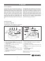
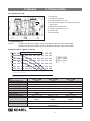
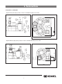
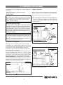
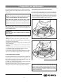
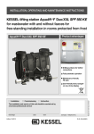
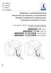
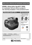
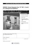
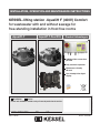
INSTALLATION, OPERATION AND MAINTENANCE INSTRUCTIONS
KESSEL-lifting station Aqualift F (400V) Comfort
for wastewater with and without sewage for
free-standing installation in frost free rooms
Aqualift F
Aqualift F Duo/XXL
Product Advantages
Additional inlet connections
possible
Fully automatic operation
Maintenance-friendly
PE-tank
Installation
Service
of this unit should be carried out by a licensed professional servicer:
Company / Telephone number
Edition 2012/05
Date
Town
subject to technical amendments
User friendly 6-line digital
display
Number 206-829EN
1. Safety Information
General safety precautions
During installation, operation, maintenance or repairs to the system, please observe the accident prevention
regulations, the applicable DIN and VDE standards and guidelines, and also the regulations of the local energy and supply companies.
The systems may not be operated in explosive areas
Electrical hazards
This system contains electrical voltages and controls rotating mechanical parts. Non-observation of the operating instructions could lead to serious damage, injury or even fatal accidents.
The system must be securely disconnected from the mains supply before commencing any work on it.
The local master switch and the cut-outs must be turned off, i.e. switch the system to zero-potential and take
precautions to ensure it cannot be switched on again. If only cut-outs are available, these must be switched
off and a sign attached to prevent third parties from switching the main fuse on again. VDE 0100 applies to
all electrical work on the system.
The control unit and the level control are under voltage and may not be opened. Only electricians may
work on the electrical equipment. The term 'electrician' is defined in the VDE 0105.
Steps must be taken to ensure that the electrical cables and all other electrical system parts are in a
fully functional condition. If any parts are damaged, the system may not be operated and/or must be immediately shut down.
Risk of burning fingers and hands
The motor may become very hot during operation
Risk of injury to fingers and hands
The pumps are equipped with a closed impeller. Therefore work on the pump may only be carried out if the
power supply has been disconnected and the rotating parts have stopped rotating. Take care on sharp edges
during maintenance or repair work.
Risk due to heavy weights
The lifting system models with one pump weigh around 45 kg, and with two pumps around 84 kg. The
systems may only be lifted or mounted by two persons with appropriate care wearing protective equipment
(e.g. protective shoes).
The pumps may only be removed slowly or placed in the pump flange opening by two persons (if suitable precautions to prevent slipping have been taken).
2
1. Safety Information
Health risk
The wastewater system transports wastewater that contains faeces; in turn this faeces may contain
harmful substances. Whenever working on the system, always ensure that there is no direct contact
between the wastewater and/or soiled system parts and your eyes, mouth or skin. In the event of direct contact,
clean the affected part of your body thoroughly and disinfect if necessary. It is also possible that the atmosphere in the tank may be harmful. Therefore before opening the cleaning aperture (or removing the pump)
ensure that the respective room is adequately ventilated or provide for (forced) ventilation during the opening
process.
Noise issues
When the pump is operated, a noise level is created that may be a nuisance depending on how the pump is
installed. If there are maximum noise level stipulations that need to be observed, appropriate measures need
to be taken. The sound damping set from KESSEL may also be helpful here.
Risk of explosion
The inside of the tank is considered to be explosive within the meaning of EN 12050 because the biological
digestive process may create flammable gases (hydrogen sulphide, methane gas). Therefore, when unscrewing the pump or the cleaning aperture lid or any other parts, ensure that the room is adequately ventilated
or provide for (forced) ventilation during the opening process. Whilst the tank is open, it is forbidden to smoke
or carry out any other activities in the respective room that could cause the gas to ignite (e.g. operation of electrical devices without encapsulated motors, metalworking etc.).
3
Table of contents
1. Safety information
...........................................................................................................Page
2
2.2
5
2. General
2.1
Area of application...............................................................Page
3. Technical data
3.1
Aqualift F Duo XXL ..............................................................Page
3.2
5. Electrical connections
9
4.1
Fitting the collecting tank ....................................................Page
11
4.3
Setting the pressure level switches ....................................Page 13
4.2
5.1
5.2
5.4
6.1
6.2
6.3
6.4
7. Inspection and maintenance
7.1
7.2
7.3
8. Malfunctions and
troubleshooting
9. Control unit
8
Instructions for safe use in hazardous areas ..................Page
5.3
6. Initial operation
Aqualift F Duo 1,1 kW; 2,2 kW.............................................Page
6
3.3
3.4
4. Installation and assembly
System description .............................................................Page
5
8.1
8.2
9.1
Electric switch unit ...............................................................Page 10
Connecting the pipes...........................................................Page
11
General notes...................................................................... Page 14
Installation of the switch unit................................................Page 14
Installation, wiring ................................................................Page 14
Control of the flow-direction ................................................Page 16
General notes ......................................................................Page 16
Pressure outlet connecting pieces.......................................Page 16
Functional description..........................................................Page 16
Functional test ....................................................................Page 18
Notes on the pump .............................................................Page 21
Notes on aeration device.....................................................Page 21
Notes on the electrical switch unit ......................................Page 22
General malfunctions ..........................................................Page 23
Malfunction messages.........................................................Page 24
Switch unit ...........................................................................Page 28
10. Spare parts and accessories
10.1
11. Warranty
...........................................................................................................Page 35
12. Declaration of conformity
13. Handover certificate
10.2
Accessory parts ...................................................................Page 30
Spare parts ..........................................................................Page 31
...........................................................................................................Page 36
...........................................................................................................Page 38
4
2. General
2.1 Area of application
The lifting stations pump wastewater with and without sewage that occurs below the sewer and backwater level fully
automatically into the sewage system in accordance with the
requirements of DIN 1986. They are only suitable for use for
domestic wastewater, for example in single family and multifamily homes, business, hotels and restaurants, department stores, hospitals, schools or similar cases. If the feed
to the lifting stations must not be interrupted during normal
operation, the lifting station must be equipped with a second
pumping device of the same capacity which switches on immediately when required (twin station instead of single station).
The KESSEL lifting station Aqualift® F has been designed for
free-standing set-up in frost-protected rooms. The respective
switch unit must be installed in a flood-proof, dry and frostprotected room. The wastewater submersible pumps are
equipped with a single-channel impeller and have a completely free passage of 40 mm. The pressure pipes must be
at least of the size DN 80, the ventilation pipes at least DN
70. Wearing media must be kept away from the pump impeller. The systems are suitable for constant wastewater
temperatures up to 35°C. A maximum temperature of 60°C
is permissible briefly (up to 10 minutes).
2.2 System description
2.2.1 Aqualift F 1,1 kW/2,2 kW
The KESSELpumping station Aqualift® F as a single or twin
system basically comprises the following assemblies:
1.8
1.3
1.5
1.4
1.6
1.2
1.7
1.1
1.4
1.6
1.9
1.2
5
1.5
1.8
1.1
1. Collecting tank made of PEHD gas and watertight, with
1.1 One or two wastewater pumps, each of which has a 5 m
connection cable
1.2 Pneumatic level control with 5 m air hose each
1.3 Cleaning opening
1.4 Connection for DN 100 inlet pipe
1.5 Connection for DN 70 ventilation pipe
1.6 Connection for manual diaphragm pump DN 32 / 40mm
diameter
1.7 DN 100 pressure outlet connecting pieces with integrated
backwater flap and aerating device
1.8 Drilling areas
1.3
2.
1.7
Electric Control Unit (see illustrations in chapter 8)
3. Accessories (not illustrated)
3.1 Brackets with screws and dowels for fixing the tank to the
floor
3.2 Rubber hose with hose clamps for the pressure pipe
connection
3.3 Sound-insulating underlay mat
Mono: Art. no. 28692
Duo: Art. no. 28693
A detailed description of the system set-up can be found in
chapter 10, Spare parts.
2. General
3. Technical Data
2.2.2 Aqualift F Duo XXL
➅
➀
➅
➁
➂
➄
➆
➃
➀ DN 150 inlet
➁ DN 100 pressure outlet
➂ DN 100 ventilation connection
➃ Twin wastewater pumps each with 5 meter power
supply cable
➄ Polyethylene collection tank
➅ Cleanout / Maintenance access
➆ Closure valve
➇ Non-return flap
➆
➇
➃
➇
2400
Versions:
Aqualift F Duo XXL (twin pumping system) 3.3 kW with DN 100 outlet, order number 28638
Aqualift F Duo XXL (twin pumping system) 4.2 kW with DN 100 outlet, order number 28639
Aqualift F Duo XXL (twin pumping system) 5.6 kW with DN 100 outlet, order number 28640
3.1 Aqualift F Duo XXL
Max. Förderhöhe H (m)
Performance Curve Aqualift ® F Duo XXL
22
20
18
16
14
12
10
8
6
4
2
0
Q min nach DIN EN 12056-4 für DN 100
400 V 3,3 kW
400 V 4,0 kW
400 V 5,6 kW
0
10
20
30
Max. Fördermenge Q (m³/h)
0
5
Max. Fördermenge Q (l/s)
40
10
Type
Nominal capacity (P2)
Rated capacity (P1)
Operating voltage
Rated frequency
Nominal current
Connection cable
Temperature of pumping medium
Weight (pump)
Protection Class rating
Operating mode
Sound level
Fusing
50
60
15
70
80
20
400 V - 3,3 kW
2,6 kW
3,3 kW
400 V DS
50 Hz
6,4 A
5 m long, 7 x 1,5 mm
40 °C
30 kg
IP 68 (24 h /3 mWs)
S2
30 Min.
< 80 db
3 x16 A
90
100
25
2
400 V - 4,2 kW
3,5 kW
3,3 kW
400 V DS
50 Hz
7,9 A
5 m long, 7 x 1,5 mm
40 °C
IP 68 (24 h /3 mWs)
S2
50 Min.
< 80 db
3 x 20 A
Characteristic C
6
2
400 V - 5,6 kW
4,8 kW
3,3 kW
400 V DS
50 Hz
10,2 A
5 m long, 7 x 1,5 mm
40 °C
31 kg
IP 68 (24 h /3 mWs)
S2
30 Min.
< 80 db
3 x 25 A
2
3. Technical Data
3.2 Aqualift F 1,1 kW/2,2kW
• Aqualift F Duo (twin pump system) 1.1 kW / 2.2 kW with DN 100 pressure outlet
Ø110
DN70
Ø75
Ø40
160
DN32
Zulaufhöhe
300
539
780
Ø110
Ø110
DN100
DN100
DN100
773
• Aqualift F Mono (single pump system) 1.1 kW / 2.2 kW with DN 100 pressure outlet
DN100
DN70
Ø75
Ø40
DN32
154
Zulaufhöhe
180
525
475
Ø110
DN100
Ø110
564
7
3. Technical Data
Type
Nominal capacity (P2)
400 V - 1,1 kW
400 V - 2,2 kW
1,6 kW
3,1 kW
1,15 kW
Rated capacity (P1)
Operating voltage
Rated frequency
Nominal current
14,4 A
Fuse
Connection cable
50 Hz
5,4 A
30,8 A
3 x 16 A Charakteristik C
5 m long, 7 x 1,5 mm2
Temperature of material pumped
Weight (pump)
30 kg
Protective rating
Sound level
400 V DS
3,2 A
Start-up current
Operating mode
2,4 kW
S1
35 °C
Max. period of perm. operation 240 Min.
< 70 db
Pump volume
Table 2
31 kg
IP 68 ( 24h; 3m WS)
20 l (Mono); 50 l (Duo)
S3
30% duty cycler
< 70 db
Performance chart
Q min DIN 1986 (vmin = 0,7m/s) for DN 80
Q min DIN 1986 for DN 100
Pumping height m
15
14
13
12
11
10
9
8
7
6
5
4
3
2
1
0
0
4
230 V
1,1 kW
400 V
2,2 kW
400 V
1,1 kW
8 12 16 20 24 28 32 36 40 44 46 48 50 52 54 56 58
pumping Q (m 3 / h)
8
3. Technical Data
3.3 Instruction for proper safe use in explosion
endangered areas
Twin Pumping System
Pump control units are available for single pump as well
as twin pump systems. Pump activation is controlled by a
pressure sensor. The control unit should not be installed
in an area that is designated as an explosion risk.
MTL 7789+ Protection
Appropriate use
Classification:
II (1) GD [EEx is] IIC
(Group II, Category (2)G, additional operating parts for
gaseous atmospheres)
The requirements of EN 50014:1997 + A1 – A2, EN
50020:2002 have been fulfilled.
EC-type examination certificate of the Zener
BAS 01 ATEX 7217
Description
II(1) G (EEx ia) IIC CE 1180 Ta = -20 deg C - +60 deg C
Operational Manual
Installation / Commissioning
This wastewater pumping system may only be installed,
connection and commissioning by a licensed professional. People operating this system must have knowledge
of regulations and codes concerning pumping systems
operated in explosion risk areas. Check to insure that the
classification of this system (see identification plate on
pumping system) meets the on-site requirements.
Allowable operation temperature range of system :
0 dec C to +50 dec C
9
Circuit ignition protection EEx ia IIC
Connection jacks (OFF, ON1, ON2, ALARM)
Maximum values:
Uo = 28 V
Io = 93 mA
Ro= 300 Ω
Po = 0,33 W
Co = 0,083 µF
Lo = 16 mH
Lo / Ro= 106 µH / Ω
Installation instructions
• Please follow all local and national safety regulations
• Please also follow this installation and operational manual
Special requirements for safe operation of this system
None
Maintenance / Servicing
• Opening the control unit cover reduces the protection
class (watertightness). Before opening the control unit
cover make sure that moisture or splash risk in the area
will not effect the control unit. If moisture or splashing
could be a risk, make sure to disconnect the control unit
from its power source before opening the cover. In general, no moisture, fluids or dirt should ever enter the interior of the control unit. Only a licensed repairman
should open the control unit cover
• After any control unit work has taken place, the control
unit cover should be closed and properly secured so
that the protection class of the control unit is assured.
• No changes to the control unit should be made. Repairs
on the control unit are not possible. In the case of a problem with the control unit, please contact the manufacturer.
• If required, system information such as the user’s manual, EC Conformity Declarations and other system relevant information can be obtained from the manufacturer.
3. Technical Data
CAUTION! When power switch OFF, power still supplied to unit!
3.4 Electrical Control Unit
3.4.1 General technical data
Ambient conditions
Permissible temperature range:
Permissible air humidity:
non-condensing
Maximum operating height:
Power consumption
max. ca.5 VA for single
(electronics without motor)
Protective class
Protective rating
0 to 50 °C
10 to 80 %
2000 m above sea level
Class 1
IP 54 when fitted
correctly
3.4.2 Supply
Mains supply
PE/N/L1/L2/L3 according to marking on terminal block for
single / twin system
Relay ‘Warning’
Switcher, opener, middle contact, closer each with max
42 V ac/dc 0.5 Amp.
Motor (single system)
Motor PE Mains connection
(spring connection on board)
Motor U T1 contactor
Motor V T2 contactor
Motor W T3 contactor
Motor 1/2 (twin system)
Motor 1/2 PE mains connection
(spring connection on board)
Motor 1/2 U T1 contactor 1/2
Motor 1/2 V T2 contactor 1/2
Motor 1/2 W T3 contactor 1/2
Operating voltage
400 / 230 V 3~ 50 Hz ± 10% rotary current (L1=230V AC /
50Hz±10%for supplying the power packs for the electronics)
Pre-fuse required
For fusing information see Page 6 Table 1 and Page 8
Table 2
3.4.3 Inputs
- Each pump has the circuit TF1
- TF2 is bridged (do not remove bridge)
- Pressure sensor with pressure tube 6 x 4 mm.
- Pressure sensor incoming approx 24 Vda < 5 mA (not
ATEX)
- Pressure sensor incoming (with ATEX) (with XXL Systems)
3.4.4 Outputs
"Malfunction" relay
Switcher; opener, middle contact, closer each with max 42
V ac/dc 0.5A for ‘malfunction’ and ‘warning’ relay; external
power should be separately fused
10
}
}
max. 4kW
max. 4kW
4. Installation and assembly
The following parts are included in the scope of supply (see
section 2.2):
- Collecting tank with all components mounted
- Electric switch unit
- Accessory parts
IMPORTANT:
The electric switch unit must be stored frost-free and dry.
If the system is not connected directly to the power supply on installation, the switch unit inc. all electric parts
must be stored accordingly.
CAUTION:
Hazard through heavy weights.
The lifting stations weigh approx. 45 kg (single system)
and approx 84 kg (twin system). The parts may only be lifted and/or assembled using suitable equipment and exercising appropriate caution. If the systems are dropped,
this can lead to irreparable damage to the system parts
(e.g. pump) or the whole system. Such damage is not covered by the warranty.
Site of Installation
The KESSEL Aqualift F wastewater lifting station is designed for free standing installation in a frost protected
room. The included control unit should be installed in a
dry, frost free and flood protected area.
4.1 Fitting the collecting tank
Maintenance work on the lifting stations, they must always
be installed in such a way that there is sufficient access to all
areas of the lifting station and replacement of all components
is guaranteed. According to DIN 12056, there must be
at least 60 cm space all round the system (on all sides and
above it) to meet this requirement.
The system must be set up at the appropriate spot in the room,
aligned horizontally and placed on practical soundinsulating material (available as an accessory from KESSEL).
The brackets, screws and dowels must be used to fix the
liftingstation to the floor to prevent movement or twisting.
INSTALLATION SITE: The KESSEL lifting stationAqualift® F
has been designed for free-standing set-up in frost-protected rooms. The respective switch unit must be installed in a
flood-proof, dry and frost-protected room.
4.2 Pipe connections
All pipes must be routed so that they drain freely with gravity.
All pipe connections must be flexible and sound insulated.
There are two types of connections possible:
I. Use of existing preformed inlets on the pump body (for
connection of inlet pipe, ventilation and manual diaphragm
pump according to Fig.Aand B) by cutting off the "front cap"
as shown in Fig. C.
Ventilation DN 70 (OD=75mm)
connection
DN 100
Manual diaphragm connection
DN 32 (OD=40mm)
OD=110mm
Illustration A: Single Pump System
Ventilation DN 70 (OD=75mm)
Inlet connection DN
100 (OD=110mm)
Attachment bracket
Tank-lifting station
Manual diaphragm connection DN 32 (OD=40mm)
Floor
mounting
Illustration B: Twin Pump System
Insulation mat
(optional)
Floor
11
4. Installation and assembly
A standard plastic pipe with gasketed socket can be pushed
over the inlet connection on the pump body (see Illustration
C).
Pipe connection
Alternatively, the connection of a plastic pipe with DN 100 for
the inlet or DN 70 for ventilation can be carried out using
connection clamps or rubber connection couplings. To
prevent damage to the pipe when tightening clamps or coupling screws, a steel re-enforcement ring should be placed
inside the inlet connection (see Illustration D.)
Hose
Clamps
Transition
hose
Saw the clip
Saw off
closed
inlet
Support ring
Inlet connection
Tank-lifting station
Hose
Clamps
ill. D:
II. Connecting pipes to drilled out additional inlet holes
on side of pump body (for inlet pipe or manual diaphragm pipe connection) using hole saw. Appropriate pipe
inlet gasket should be fit into previously cut out inlet hole,
interior portion of gasket should be lubricated and then
pipe should be push fit (see Illustration. E)
Attachment bracket
Pipe
connection
Hole drilled
ill. C:
Tank-lifting station
ill. E
* KESSEL-Accessory parts
12
4. Installation and assembly
IMPORTANT
In the case of all the connections drilled at the side it must
be remembered that the level control is adjusted in such
a way that during normal operation the water level in the
container only reaches up to or just below the lower edge
of the moulded inlet pipe connecting piece on the side.
For this reason, a respective water level will result in all
pipes that are connected lower down. In the case of inlet
pipes this means that dirt deposits cannot be excluded
and may lead to the pipe becoming blocked in extreme situations.
l Inlet pipe
The inlet pipe must be laid with a downward slope / gradient
to the KESSEL lifting station in accordance with DIN 1986
and be routed as straight as possible. Connection to the tank
can be carried out as described in Section I or II above.
The ventilation pipe sets up pressure compensation to the
fresh air for the air flowing into or out of the system during
emptying or filling. According to DIN 1986 the size of the ventilation pipe must be at a minimum DN 50 for these lifting stations and must be routed over the roof to avoid odour problems.
Connection to the tank can be carried out as described in
Section I or II above.
l Pressure pipe
The pressure pipe for directing the soiled water into the sewage system must be connected directly to the respective
pressure pipe connection. According to the regulations of EN
12056, the outlet pressure pipe must layed above the backwater level and connected to a ventilated drainage pipe.
The rubber hose included in the scope must be pushed about
4 cm over the pressure connecting piece at the pressure
connection and fixed in place using a hose clamp as a means
of acoustic insulation and to prevent transmission of forces.
Connection of the rubber hose is not an interlocking connection.
It must be set up on site using brackets. The pressure pipe
must be connected (see above) in such a way that no forces
are transferred to the system and there is no direct contact
with the building (structure-borne noise). No other drainage
fixtures may be connected to the pressure pipe.
Air-tightness and material strength must be guaranteed
under pressure load, too. This must be checked during initial operation.
The pressure pipe must have a flexible connection to the
building to prevent water hammer forces from being transferred to the builiding. When cast metal or steel pressure
pipes with low absorption properties are used, a water hammer arrestor must be included in the pressure pipe from pumping heights from 5 m.
Pressure resistant non-return flaps available as accessories:
DN 80 backwater flap made of cast iron (art. no.: 206-199)
13
DN 100 backwater flap made of cast iron (art. no.: 206-198)
Aerating device (art. no. 206-200)
A shut-off valve must be installed in the pressure pipe on site
in accordance with EN 12056. For this, we recommend the
non-return valves for mono systems (art. no. 28683) and for
duo systems (art. no. 28694) from the KESSEL range of accessories.
4.3. Level measurement
Level measurement takes place using a pressure sensor and
submersible pipe. The transparent air hose must always be
routed rising to the switch unit so that no condensation can
collect in the air hose. Perfect function is only guaranteed
when permanent pressure compensation takes place between the switch unit and lifting station. Excess air hose lengths must be shortened. The switching levels are pre-set and
can be changed using the switch unit. More detailed information is available from KESSEL Customer Services.
l Aqualift F XXL Models
Float switch settings
Float switches on the Aqualift F XXL lifting stations have
been installed and set at the factory. Do not attempt to change the location or level of these float switches as it will only
lead to problems with the operation of the lifting station.
Four float switches are included in the XXL lifting stations
(pump off, pump 1 on, pump 2 on and alarm). The alarm level
is approximately the same height as the inlet level of the lifting station.
In the case that different activation levels are required, the
float switches need to be adjusted accordingly. It is important
that the alarm level float switch activation level is not set higher than the base of the inlet level and also that the Off float
switch is not set too low to prevent the pump from pumping
too low and intaking air.
5. Electrical connections
Attention:
Only qualified electricians may carry out the work on electrical equipment described below. Before any work is
carried out on the control unit, the pump or level control,
the main power supply to the lifting station must be turned
off and fuses must be switched off, i.e. be voltage-free and
secured against being accidentally re-activated during
service work.
5.1 General instructions
An external main switch must be installed for the electric
switch unit that can be used in an emergency to switch off all
the downstream circuits independently of the control unit.
This must be assigned clearly to the switch unit. All connected cables must be strain-relieved. Screw connections not
used must always be sealed properly.
IMPORTANT:
All the cables connected to the electrical switch unit must be
fixed in place using suitable measures (e.g. cable ties) so that
they do not cause a hazard in the 1-error case, i.e. if a
connection becomes loose.
5.2 Mounting the switch unit
Screw the housing cover with max. 1 Nm. Install the switch
unit provided in a frost-free, dry, flood-proof and well-ventilated room. The switch unit has been designed for vertical
wall-mounting on a solid base. Sufficient air circulation in the
room of installation must be insured to prevent excessive
temperatures. The unit is mounted using 4 screws (Ø 6 mm)
at the corners of the housing (drilling template in the packaging box). The mounting holes are accessible after the cover
has been fully opened.
5.3 Installation, wiring
The pump cable and pressure sensor cables have a standard length of 5 m. The pump cable may be extended by
using a VDE certified extension connection. In the case that
the pressure sensor cable is to be extended, the extension
connection must be completely air right and the cable must
be run in a positive slope from the lifting station to the control unit (no loops or kinks).
Please heed national and local safety regulations. If these
are not observed, personal hazard may be the result. In addition, no liability or warranty will be granted. After work has
been completed, the housing cover must be sealed properly
again.
In the case that the lifting station has a pressure sensor, the
cable for this sensor should be laid separately from the
power cable and the pump cable in order to insure proper
operation of the pressure sensor.
14
5. Electrical connections
The individual connection jobs are listed in the following table and in the connection diagrams on pages 27 and 29. The explanations in chapter 8, Electric switch unit, must also be heeded (position of the control elements, view of the inside of the
switch unit).
SINGLE PUMP LIFTING SATION – please follow all safety instructions and regulations!
Work to be completed
Description
Battery connection
Mains connection
Motor power cable
Motor temperature sensor
Level measurement
Outputs "Malfunction"
and "alarm / warning"
• Both batteries (2 x 9V) must be connected on the board.
• Connect the mains supply cable L1 / L2 / L3 / N / PE at the terminal block using
screw connection.
• N and PE always have to be connected.
• The required fusing must not exceed 16 Amps for each phase.
• An improper connection (Phase and N improperly connected for example) will
activate the integrated fuse (315 mAT)
• Connect the motor supply cable U/V/W to the connector in the right direction in
the lower screw terminals T1 / T2 / T3. The direction of rotation of the motor must
be heeded.
• PE must be connected with TF1 and TF2 to the terminal block on the board underneath the motor protection switch.
• Wire 4 of the motor power cable must be connected to the lowest terminal of the
terminal block TF2-TF1. Wire 5 of the motor power cable must be connected to
the middle terminal of the terminal block TF2 TF1. The input TF2 is bridged with
a 2-pole jumper, i.e. the middle terminal is double occupied. Jumper must not be
removed!
Connection to the pressure sensor
The transparent air hose must always be laid with a positive slope to the control
unit (no loops or kinks in the cable). The connection of the air sensing hose to
the control unit must be firmly and properly connected.
• The "malfunction" and "warning" messages are issued via a relay (changeover
contact) without protective circuit. Inductive loads must be dejammed externally. The quiescent state (currentless) of the relays is printed on the circuit board.
It means "malfunction" and "warning" message is switched on.
• 42 V DC/ 0.5 A
15
5. Electrical connections
TWIN PUMP LIFTING SATION – please follow all safety instructions and regulations!
Work to be completed
Description
Battery connection
Mains connection
Motor power cable
Motor temperature sensor
Level measurement
.
Outputs "Malfunction"
and "alarm / warning"
• Both batteries (2 x 9V) must be connected on the board.
• Connect the mains supply cable L1 / L2 / L3 / N / PE at the terminal block using screw
connection.
• N and PE always have to be connected.
• The required fusing must not exceed 16 Amps for each phase.
• An improper connection can damage or destroy he control unit.
• Connect both the motor supply cables U/V/W to the connector in the right direction in the
lower screw terminals T1 / T2 / T3 (Pump 1 left, Pump 2 right). The direction of rotation
of the motor must be heeded.
• PE must be connected with TF1 and TF2 to the terminal block on the board underneath
the motor protection switch (Pump 1 left, Pump 2 right).
• For both pump 1 and 2 - Wire 4 of the motor power cable must be connected to the
lowest terminal of the terminal block TF2 TF1. Wire 5 of the motor power cable must
be connected to the middle terminal of the terminal block TF2 TF1.
• Input TF2 Pump 1 and Pump 2 is bridged with a 2-pole jumper, i.e. the middle terminal is double occupied. Jumper must not be removed!
Connection to the pressure sensor
The transparent air hose must always be laid with a positive slope to the control unit
(no loops or kinks in the cable). The connection of the air sensing hose to the control
unit must be firmly and properly connected.
• The "malfunction" and "warning" messages are issued via a relay (changeover contact)
• without protective circuit. Inductive loads must be dejammed externally. The quiescent
state (currentless) of the relays is printed on the circuit board. It means "malfunction"
and "warning" message is switched on.
• 42 V DC/ 0.5 A
5.4 Checks
- Setting of motor protection switch
The motor protection switches must be set to the
values for rated current of the respective pumps
as specified in section 3.
16
6. Initial operation
6.1 General instructions
Initial operation
Initial operation must be carried out by a qualified expert, with
the direct supplier of the wastewater lifting station responsible for his availability. During initial operation, a test run with
water is required over at least two switching cycles. During
the test run, dry running must be avoided. Before, during and
after this test run, the following must be checked:
a) The electric fuse protection of the wastewater lifting station according to IEC or local regulations
b) The direction of rotation of the motor
c) The gate (actuation, open position, air-tightness)
d) The switching and setting of switching heights in the
collecting tank, in as far as these are not pre-set by the
manufacturer
e) Air-tightness of the system, fittings and pipes
f) Check on operating voltage and frequency
g) Functional test on the backflow preventer
h) Malfunction warning device
i) Attachment of the pressure pipe
j) Motor protection switch; check by briefly screwing individual fuses out (two-phase run)
k) Oil level (if oil chamber exists)
l) Pilot lamps and counters
m) Functional test for any manual pump that may be installed.
Initial operation must be documented in writing, whereby important data e.g. setting of the motor protection switch and
status of operating hours counter must be noted.
This initial operation may only be carried out by authorised
specialist staff.
DIN 1986, part 3, must be heeded during the initial operation of lifting stations.
CAUTION:
Before initial operation the inlet pipes and the pumps must
be cleaned of solid materials such as metal, sand etc.
Before initial operation the pump must be filled with pumping
fluid up to the height of the ventilation bore hole of the pump
housing.
The pump must not intake air!
After the complete and correct installation of the complete system and all the additional parts as well as the pipe and electrical installations, the system can be put into operation.
Any shut-off valves must be opened. Make sure before you
put the system into operation that the nominal voltage and
type of current specified for the system correspond to the nominal voltage and type of current on site.
Check the system installation/cabling carefully before you
put the system into operation. Is the protective earthed conductor working? Have the relevant standards/guidelines
been heeded, particularly with a view to the potentially explosive area? DO NOT put the system into operation if there
is any damage to the motor, switch unit or cables visible. Always follow the safety instructions in chapter 1 of this manual
17
IMPORTANT:
All screw connections must be checked for a tight fit.
6.2 Pressure outlet connecting pieces
The pressure outlet connecting pieces of the lifting stations
are equipped with a backwater flap with aerating device as
standard for each pump. The aerating device must always be
in operating position (see Fig. 1).
ill. 1
The flap (dotted line) is opened exclusively by the pumping
flow of the pump.
6.3 Operating the control unit (from model year 01/10)
The lifting station is operational when the POWER LED light is
on and no error or malfunctions (ALARM LED) are displayed.
As the wastewater level rises in the tank, the increased air pressure is sensed by the pressure sensor which in turn will activate the pump. As the pump pumps out wastewater the pressure
will be reduced inside the tank and as soon as the pressure falls
below the ON level, the pressure switch will signal to the control unit to turn off the pump – the pump will stop running after
the post run time of the pump has elapsed.
In the case the the pump runs longer than the pre-set maximum
pump run time, the pump will automatically turn off and a warning message will be shown via the orange LED on the control
unit and the warning relay will activate. The warning message
and the warning relay activation will be stored until the ‘Alarm’
button has been pressed – only after this has occurred can the
pump(s) begin operating again. The pump(s) can be manually
activated by pressing the ‘Pump Test’ button twice.
6. Initial operation
6.4 Control unit operation
Digital display
Aqualift F Mono 400V
Cursor buttons
OK button (confirmation button)
Niveau
Level
ESC
OK
Return button
Power LED showing operational status
Alarm LED
Pumpe
Pump
Pump can be manually started by pressing
twice the Pump button on the control unit
Aqualift F Duo 400V
Pumpe I
Pump I
ESC
Note – In case the control unit cover is opened,
the main power switch to the control unit must be
turned off.
OK
Pumpe II
Pump II
System Start
System Diagnosis
After a re-start (for example after a power failure)
the system goes back into
automatic operation and
displays the system information.
Display Systeminfo
After the initial commissioning of the system or
after a re-initialisation
after a reset, the control
unit requests the following information.
Language
Date / Time
System Configuration
Pressure switch
Press. switch+Alarm
Press. switch+Komp
Press. switch+Alarm+Komp
Float switch
System information
System size
Sensor configuration
Date and Time
Level indicator
Error / Event
System size
When power is initially connected to the control
unit, a basic system check is automatically conducted which includes 4 basic points. In the digital display, the following is shown:
1. Language desired for control unit operation
2. Current date and time
3. Level sensor type
4. Type of pumps in lifting station (kW)
By using the up and down cursor buttons on the
control unit, the desired setting can be chosen by
pressing the OK button. As soon as all 4 settings
have been selected, the control unit loads the settings into the memory and then places the lifting
station into operation. The lifting station is now
fully operational.
Lifting station 1,1 kW
Lifting station 2,2 kW
Pumping station 1,3 kW
Pumping station 1,9 kW
Custom system 4 Amp
Systeminfo
Lifting station 1,1 kW
Pressure switch
Date and Time
wastewater level
18
6. Initial operation
Control unit digital display instructions
The digital display operation is in the system information
as well as in three separate main menu sections. Pressing
one of the control unit buttons will automatically back light
the digital display.
OK-Button:
confirms the setting and enters into the
next setting level
ESC-Button: returns the control unit to the previous setting / step
▲:
Navigation within a level
▼
An alarm signal can be confirmed and muted
by pressing the Alarm button once. In the
case that the error has been fixed, pressing
the Alarm button again will also erase the optical LED warning light.
optical alarm. The audible alarm can be confirmed and
cancelled by pressing the Alarm button. The control unit
will run for at least 72 hours in stand-by mode. When the
72 hour period is over, the control unit will automatically
turn itself off. In the case that power is returned within 1
hour, the control unit will return to operation in the same
mode it was in when the power failure occurred. If this is
not the case, the control unit will perform an automated recommissioning when power is restored. This can also be
accomplished by pressing the Alarm button for an extended period.
Note:
Certain control unit display menus / levels are password
protected. This protects the unit from improper operation.
In the case that the error has not been fixed, pressing the
Alarm button again will cause the audible alarm to re-activate
During a power outage, the pumping system is not operational – the control unit will go into stand-by mode meaning battery operation. This is signalled by an audible and
6.4.1 System-Menu
0.
Systeminfo
System
information
Leistungsgröße
System size
Sensorkonfiguration
Sensor
configuration
Datum
Uhrzeit
Date
and Time
Füllstandsanzeige
Level indicator
Fehler/Ereignisse
Error
/ Event
Beispiel:
Information
Informationen
Maintenance
Wartung
Settings
Einstellungen
display of level including number
0.
Systeminfo
Pump:
Hebeanlage 1,1kW
Floater:
Drucksensor
24.12.2009
20:45:16
Level:
Füllstand:
130cm
mm
Lifting station type
sensor type
Date and Time
current wastewater level
19
6. Initial operation
6.4.2 Information menu
Information
Systeminfo
Informationen
Systeminfo Informationen
Uhrzeit: 00:00:00
Uhrzeit: 00:00:00
Schwimmer
1: Ein / Aus
Schwimmer
1: Ein / Aus
TX:
TX:
TX1:
TX1:
Wartung
Maintenance
Wartung
Positions
Einstellungen
Einstellungen
Attendend
time
Betriebsstunden
B
Events/Errors
Ereignisse
/ Fehler
Command type
Steuerungstyp
Maintenance Date
Wartungstermin
Water
level
Wasserhöhe
Parameter
Parameter
Operating hours
Displays all running times of the system.
G
Events / errors
Chronological error and event display (see also Chapter
10 "Malfunctions and troubleshooting")
All modifications to the settings are saved here.
Control type
Displays the output parameters and the sensor configuration incl. combinations:
• pressure sensor (pressure)
• alarm
• compressor (comp.)
• float
Maintenance date
Shows the next and the last maintenance date.
Note: Dates are only available if they have been filed in
the 'Settings' menu by the servicing partner.
Current measured values
Displays the mains voltage, current, battery voltage and
filling level.
Parameter
Displays all the system control parameter settings:
Mains-ON delay, height of the dynamic pressure bell,
switch-on lock, measuring range, ON1 level.
6.4.3 Maintenance menu
Information
man. operation
Positions
Maintenance Date
Maintenance
SDS
6.4.4 Settings menu
Information
Maintenance
Positions
Parameter storage
Date/time
Sensor storage
Manual operation
In manual mode, the automatic mode is deactivated.
Self-diagnosis system (SDS)
System test similar to initialisation.
Maintenance date
The next maintenance date is entered by the servicing
partner.
Only authorised maintenance staff may change
the settings. To do this, the KESSEL Customer
Service must be contacted for the password.
Communication
Nominal size
language
Reset
20
7. Inspection and maintenance
The system must be inspected once a month by the operator with regard to serviceability and leaks by observing a switching cycle.
CAUTION:
Always disconnect the system from the mains supply
before servicing! Observe the safety instructions!
7.2 Information about the backflow preventer
The backflow preventer can be used to completely empty the
pressure line by manually lifting the check valve of the lifting
system. To do this, turn the flap opener with a size 8 (15 mm)
wrench and hold (see Fig. 2) until the pressure line is empty.
After this, the flap opener must be returned to its original position or the marked operating setting (see Fig. 3).
Only authorised qualified persons may carry out the
inspection and maintenance tasks described below.
Repairs may only be carried out by the manufacturer.
When servicing lifting systems, the DIN 1986, Part 3 must be
observed. Maintenance must be carried out regularly by authorised qualified persons.
IMPORTANT:
All screws may only be tightened with a maximum
force of 3 Nm.
The following tasks must be carried out:
• Visual inspection of the entire system, the pumps and the
fittings
• Thorough cleaning of the entire system and the pump
• Inspection of the entire system and pump casing for external damage and visible wear
• Inspection of the pump to ensure it runs smoothly and for
wear and deposits
• Inspection of the connection lines for mechanical damage
and wear
• Inspection of the seal connections for leaks; in the event of
recognisable wear, exchange the seals (e.g. O-ring)
• Check the insulation on the pump motor
• If necessary test the function of the manual closure valve.
• The check valve must be replaced after 2 years service.
Ill. 2
7.1 Information about the pump
The pump should be inspected at regular intervals. When the
operating noises become louder or there are vibrations in the
pipe system, the pump casing and impeller need to be
checked for any ingrained dirt or wear.
To do this, unscrew the four attachment screws on the motor
unit and remove from the pump casing.
When inspecting the pump casing, note that the venting borehole must remain open under all operating conditions.
21
Ill. 3
Note:
When the screw connections on the lower and upper flange of the valve casing are unscrewed, the entire valve casing can be removed for cleaning and maintenance purposes. Of course before this happens the pressure line must
be blocked and drained.
7. Inspection and maintenance
Threaded hole for easy pump disassembly.
ill. 4
ill. 5
7.3 Information about the electrical switchgear
• The battery is a wear part and should be checked once a year
and exchanged if necessary. Ensure that the replaced battery
is disposed of correctly in an environmentally compatible manner. It may only be replaced with a battery of the same type.
• The contactor is a wear part and should be checked once a
year and exchanged if necessary. Ensure that the replaced
battery is disposed of correctly in an environmentally compatible manner. It may only be replaced with a battery of the same
type.
• After the maintenance work the switchgear lid must be closed
again correctly (contact protection!).
• Repairs may only be carried out by the manufacturer.
22
8. Malfunctions and troubleshooting
The following trouble shooting and checks should only be performed by qualified service workers. When in doubt please
contact the KESSEL Customer Service Department or the authorized company who originally installed the system.
8.1 General malfunctions
1
Malfunction
Pumps do not start
Cause
Remedial measure
Motor protection switch has triggered, Remove pump; eliminate blockage (object) in
the impeller or housing area
motor is blocked
Motor turns sluggishly
Maintenance / repair by Customer Services
1 or 2 phases have no current Control Check fuses and power supply cables
fails on account of heavy fluctuations
in the mains power supply
Phases are reversed
2
Pumps are running but
alarm level is reached
Pressure sensor not airtight or PE
hose not connected
Too much wastewater entering
system
Pump performance is not sufficient
3
Check proper phase connection and swap if
required
Check all screw connections for air-tightness
Check to see if unusually large amount of wastewater are entering the system – if required
temporarily stop draining specific drainage fixtures into the lifting station, if possible, disconnect
drainage fixtures connected to the lifting station
• Remove any obstructions located in impeller or
pump housing
• Remove any obstructions located in outlet or
outlet assembly
• Pumps no longer offer original performance,
replace pumps
• Lifting station was improperly specified and is
not designed for the site’s requirements –
contact KESSEL Customer Service Department
Ventilation setting may not be in ope- Set non-return flap in closed position (operational position)
ration mode
Wastewater does not drain Lifting station not properly set
Turn main control unit power switch to the ‘ON’
position
away – lowest fixtures
connected to lifting station Power cable to control unit not
Check power supply to control unit – check fuses
are flooded.
receiving power
Wastewater level sensing system not Check level sensor for blockages and check for
proper operation
operational
Main inlet pipe to lifting station blocked Check and clean main inlet pipe if necessary
Gate closure valve to lifting station (if Check to make sure gate closure valve (if exiexisting) may be closed or only parti- sting) is in the fully open position
ally open
Wastewater temperature entering lif- Reduce temperature of wastewater entering lifting station over extended period of ting station
time (15 minutes) too high.
4
Lifting station suddenly Pump may be damaged due to foreign
objects
begins operating loudly
Foreign object may be located in intake / impeller area
23
Check pump for damage and fix / replace if necessary
Check intake area and impeller for foreign
object. Remove objects or replace pump if
necessary.
8. Malfunctions and troubleshooting
Malfunction
5
Smelly odour during
operation
Sharp odour during
operation
6
7
Lifting station turns on too
frequently, pumps start
without reason
Cause
Remedial measure
Pump is not water tight
Check pumps – if required have customer service repair or replace pump(s)
Lifting station is not water tight / air Check ventilation, inlet, pressure outlet and
cover for water tightness – repair if required.
tight
Motor is too hot – overloaded
Protectors too hot due to faulty level
switching
Wastewater amount entering lifting
station too high
Lifting station not-return valve not
operating correctly – wastewater
which was pumped out of the system
is flowing back into the system after
pumps stop due to malfunctioning
non-return valve.
Check motor and impeller for free, easy operation / rotation. Make sure motor protection
switch is operational
Too frequent pump operation due to excessive
wastewater levels – contact KESSEL Customer Service
Check pump for pump activation problems
Check wastewater amounts entering system
and correct if necessary
Check non-return valve in outlet of lifting station for blockage or malfunction. Clean or replace if necessary.
Lifting station operates Foam build up inside lifting station
continuously or displays body
switching malfunctions
Station body / pump(s) effected by
heavy grease / fat build up
Reduce amount of soap, detergent and shampoo entering the lifting station
Lifting station not pumping
out sufficient wastewater Phases incorrectly connected
amounts
Pump rotation backwards
Swap phase connections to control unit
Clean entire lifting station, reduce amounts of
oils / greases entering lifting station
Check pressure sensor cable between lifting
Ventilation pipe blocked
station and control unit.
Pressure sensor system clogged or Make sure cable is not kinked or coiled in a
blocked, switching levels incorrectly loop. Continuous slope from lifting station to
set.
control unit is required (not loops or kinks). Fix
or replace if necessary.
Remove pressure sensor system and clean.
Check pressure controls and levels
8
Check pump power supply cables for proper
connection
8.2 Warning messages
All warning message will be displayed on the control unit. In the case that multiple warning messages occur at one time –
individual warning messages can be read by scrolling down the control unit’s digital display.
24
8. Malfunctions and troubleshooting
Error messages / troubleshooting
= lit up
= off l = slow flashing
Battery error
❍ = fast flashing
- acknowledge alarm and alarm key
- check if the battery is connected
- exchange discharged battery
- the charging status of the batteries can be tested in menu 1.5.3
(battery power check)
- after acknowledging the signal tone, press the alarm key again
--> switchgear continues to work without the batteries
--> no protective function during power outage
Mains failure (battery mode)
- Check if the mains failure has just affected the room or the entire building
- Check the cut-outs / check the error current circuit breaker
- Check if the mains supply cable is defective
- Check the micro fuse in the switchgear
(only use a fuse with the same rated value and tripping characteristics).
Motor error
Cause: TF1, TF2, motor circuit breaker
Remedy:
- If display shows “Motor circuit breaker 1/2”
--> check the motor circuit breaker 1/2
Duo Pumpe 1
Duo Pumpe 2
- If display shows “TF1a / TF2a”
--> the lower winding temperature switch has triggered
--> resets automatically when the motor cools down
Error message must be acknowledged with the alarm key.
- If display shows “TF1b / TF2b”
--> for lifting systems, bridge TF2 defective/not installed
Exchange/install bridge
25
8. Malfunctions and troubleshooting
Limit running time error / limit running count error
- Limit running count error: Pump is activated more than 20 times in 3 min
--> Check the air pipe between the immersion tube/immersion bell and switchgear for
water inclusions
--> Check if the immersion tube/immersion bell is blocked
--> Check intake, check pump capacity
Duo Pumpe 1
- Limit running time error: Pump runs for longer than 240 min without stopping
--> Check the air pipe between the immersion tube/immersion bell and switchgear for
water inclusions
--> Check if the immersion tube/immersion bell is blocked
--> Check intake, check pump capacity
Duo Pumpe 2
Sensor error (only for XXL-systems)
Duo Pumpe 1/2
- Level error:
A float indicates a level although no float below has triggered (wrong sequence float)
--> Check the float cable of the float below
--> Check the function of the float in the tank (lift)
--> The pump(s) is/are switched on.
The switchgear works with the recognised level.
Revolving field / phase errors
- Revolving field error:
Wrong revolving field when connected to mains Switchgear
--> exchange 2 phases
Duo Pumpe 1/2
- Phase error:
Phase L1 or L2, L3 do not exist
--> Check connection to switchgear, power cable, cut-outs,
Check error current circuit breaker
--> If L1 fails, the revolving field direction cannot be recognised.
--> If L1 fails, the switchgear goes into battery mode
--> In the case of revolving field errors, the pumps are not switched on in manual or
automatic mode
26
8. Malfunctions and troubleshooting
Relay switching cycles
Duo Pumpe 1
Main contactor has exceeded 100,000 switching cycles
--> can be acknowledged, main contactor does another 1000 switching cycles before a
new message is sent
--> Exchange the contactor --> Contact the Customer Service
--> After 100000 switching cycles the relay switching cycle error is repeated after every
further 1000 cycles
Duo Pumpe 1
Relay error
Main contactor no longer switches off
--> Disconnect the switchgear from the mains
--> Exchange the contactor --> Contact the Customer Service
Duo Pumpe 1
Duo Pumpe 2
Alarm level exceeded
Duo Pumpe 1
Alarm level is achieved by the water level
--> Alarm turns off automatically if the alarm level has been undercut again
--> LED only turns off after it has been acknowledged manually
--> Check intake
--> Check level recording and switch points
27
9. Control unit
9.1.1 Switch unit (single pump system) (from model year 01/10)
9.1.2 Switch unit (double pump system) (from model year 01/10)
28
9. Control unit
9.1.3 Switch unit (double pump system) Aqualift XXL
29
10. Spare parts and accessories
10.1 Accessories
Description
Emergency manual hand pump
Closure valve for emergency manual hand pump
Flexible coupling with twin securing brackets
Flange – pipe connection
Plastic closure valve for non-pressure piping
Vibration mat (for under lifting station)
Pipe inlet sealing gasket
DN 40
DN 70
DN 100
DN 80
DN 150
DN 100
DN 150
Single pump station
twin pump station
DN 50
DN 70
DN 100
DN 125
DN 150
Hole saw drill bit DN 50 - DN 150
Battery (quantity 1)
Closure valve for single pump system
DN 100
Closure valve for twin pump system
DN 100
Compressor for air pressure sensor allows more reliable air pressure operation
Air filter for compressor (28048)
Motor protection switch 2.5 – 4 Amp
Motor protection switch 4 – 6.3 Amp.
Motor protection switch 6.3 – 10 Amp
Protector
Level sensor
Float switch for Aqualift F XXL Systems
Motor (complete) for 2.6 kW Aqualift F XXL System
Motor (complete) for 3.5 kW Aqualift F XXL System
Motor (complete) for 5.6 kW Aqualift F XXL System
Control unit for Aqualift F XXL 2.6 kW pump lifting station (ATEX)
Control unit for Aqualift F XXL 2.6 kW pump lifting station
Control unit for Aqualift F XXL 3.5 kW pump lifting station (ATEX)
Control unit for Aqualift F XXL 3.5 kW pump lifting station
Control unit for Aqualift F XXL 5.6 kW pump lifting station (ATEX)
Control unit for Aqualift F XXL 5.6 kW pump lifting station
see also KESSEL-Catalog
30
Order Number
28680
28681
28660
28661
28663
28655
28658
28698
28699
28692
28693
850114
850116
850117
850118
850119
50100
197-081
28683
28694
28048
363-140
363-134
363-135
363-136
363-151
363-138
185-043
245-401
245-402
245-406
363-132
363-177
363-176
363-178
363-196
363-197
10. Spare parts and accessories
14
10.2 Replacement Parts
10.2.1 Single Pump lifting station
16
15
17
15
13
10
12
11
9
Pos.
1
2
3a
3b
4
5
6
7
8
9
10
11
12
13
14
15
16
17
18
19
19
Quantity
1
1
1
1
1
1
1
1
1
1
2
1
1
1
1
4
8
8
8
1
1
1
Order-Nr.
206-004
206-161
367-002
367-003
240-051
206-208
206-018
363-104
363-105
28663
206-054
206-042
049-010
049-011
049-005
017-095
206-074
017-199
017-012
367-007
206-228
206-227
31
9
Name
Single pump tank
Pump flange – complete
Motor (complete) 1.1 kW / 400V
Motor (complete) 2.2 kW / 400V
Outlet assembly with non-return flap – DN 100
Pressure sensor for single pump systems
Access cover
Control unit Komfort (1.1 kW)
Control unit Komfort (2.2 kW)
DN 100 connection coupling
Securing brackets
Flange gasket
Gasket
Gasket
O-ring
Screws
PT-screws
M8 x 25 screws
Washer
Gasket
PE air pressure tube 6 x 4 mm (5 meter length)
PE air pressure tube 6 x 4 mm (10 meter length)
10. Spare parts and accessories
10.2.2 Twin Pump lifting station
22
15
16
20
21
Pos.
1
2
3a
3b
4
5
6
7a
7b
8
9
10
11
12
13
14
15
16
17
18
20
22
22
Quantity
1
2
2
2
1
1
1
1
1
1
2
2
2
1
1
2
8
4
14
14
4
1
1
Order-Nr.
206-005
206-161
367-002
367-003
240-056
206-224
206-018
363-121
363-122
28663
003-144
206-054
206-042
049-010
049-011
049-005
017-095
206-074
017-199
017-012
017-213
206-228
206-227
Name
Twin pump tank
Pump flange – complete
Motor (complete) 1.1 kW / 400V
Motor (complete) 2.2 kW / 400V
Outlet assembly with non-return flap – DN 100
Pressure sensor for twin pump systems (beginning 01/ 2010)
Access cover
Control unit Komfort for twin pump sytem (1.1 kW)
Control unit Komfort for twin pump system (2.2 kW)
DN 100 connection coupling
Pipe clamp D = 120 for DN 100
Securing brackets
Flange gasket
Gasket
Gasket
O-ring
Screws
PT-screws
M8 x 25 screws
Washer
Gasket
PE air pressure tube 6 x 4 mm (5 meter length)
PE air pressure tube 6 x 4 mm (10 meter length)
32
10. Spare parts and accessories
10.2.3 Air pressure sensor L = 175 mm
➂
Single pump systems (206-208)
Twin pump systems (206-224)
➁
Pos.
1
2
3
➀
Order nr.
197-333
197-340
197-339
206-228
206-227
1
1
1
1
1
Name
Screw cap
Clamping ring
Fastening nut.
PE air pressure tube 6 x 4 mm (5 m)
PE air pressure tube 6 x 4 mm (10 m)
10.2.5 Single pump outlet assembly with non-return flap ( 240-051)
➁
➂
➃
➀
➄
33
Pos.
1
2
3
4
5a
5b
1
1
1
1
1
1
Order-Nr.
240-046
240-048
240-038
240-037
240-068
240-069
Name
Outlet housing
Connection tip
Securing bolts
O-ring
Non-return flap for 1.1 kW
pump models
Non-return flap for 2.2 kW
pump models
10. Spare parts and accessories
10.2.6 Single pump outlet assembly with non-return flap
Pos.
1
2
3
4a
4b
6
7
8
9
10
11
Quantity
2
2
1
2
2
4
8
8
8
8
2
Order-Nr.
240-007
240-045
240-009
240-068
240-069
240-027
240-058
240-059
240-038
240-039
049-005
Name
Outlet housing
Outlet housing cover
T-connection DN 100
Non-return flap for 1.1 kW pump models
Non-return flap for 2.2 kW pump models
O-ring
M6 screw
M6 bolt
M8 screw
M8 bolt
DN 125 O-ring
34
11. Warranty
1. In the case that a KESSEL product is defective, KESSEL has
the option of repairing or replacing the product. If the product
remains defective after the second attempt to repair or replace the product or it is economically unfeasible to repair or replace the product, the customer has the right to cancel the
order / contract or reduce payment accordingly. KESSEL
must be notified immediately in writing of defects in a product.
In the case that the defect is not visible or difficult to detect,
KESSEL must be notified immediately in writing of the defect
as soon as it is discovered. If the product is repaired or replaced, the newly repaired or replaced product shall receive
a new warranty identical to that which the original (defective)
product was granted. The term defective product refers only
to the product or part needing repair or replacement and not
necessarily to the entire product or unit. KESSEL products are
warranted for a period of 24 month. This warranty period begins on the day the product is shipped form KESSEL to its customer. The warranty only applies to newly manufactured
products. Additional information can be found in section 377
of the HGB.
35
In addition to the standard warranty, KESSEL offers an additional 20 year warranty on the polymer bodies of class I / II
fuel separators, grease separators, inspection chambers, wastewater treatment systems and rainwater storage tanks. This
additional warranty applies to the watertightness, usability
and structural soundness of the product.
A requirement of this additional warranty is that the product is
properly installed and operated in accordance with the valid
installation and user's manual as well as the corresponding
norms / regulations.
2. Wear and tear on a product will not be considered a defect.
Problems with products resulting from improper installation,
handling or maintenance will also be considered a defect.
Note: Only the manufacturer may open sealed components or
screw connections. Otherwise, the warranty may become null
and void
01.06.2010
36
Note
37
13. Important contacts / Info
Separator Type:
__________________________________________________________
Day / Hour
__________________________________________________________
Project description /Building services supervisor __________________________________________________________
Address
__________________________________________________________
Builder
__________________________________________________________
Telephone / Fax
__________________________________________________________
Telephone / Fax
Address
__________________________________________________________
__________________________________________________________
Planner
__________________________________________________________
Telephone / Fax
__________________________________________________________
Address
__________________________________________________________
Contracted plumbing company
__________________________________________________________
Telephone / Fax
__________________________________________________________
Address
KESSEL-Commissions no.:
__________________________________________________________
System operator /owner
__________________________________________________________
Telephone / Fax
__________________________________________________________
Address
__________________________________________________________
User
__________________________________________________________
Telephone / Fax
__________________________________________________________
Address
__________________________________________________________
Person of delivery
__________________________________________________________
Other remarks
__________________________________________________________
The system operator, and those responsible, were present during the commissioning of this system.
____________________________
Place and date
____________________________
Signature owner
38
____________________________
Signature user
Handover-Ceritficate
Handover certificate (copy for the company carrying out the installation)
❏
❏
❏
The initial operation and instruction was carried out in the presence of the person authorised to perform the
acceptance and the system operator.
The system operator/person authorised to perform the acceptance was informed about the obligation to service the product according to the enclosed operating instructions.
Initial operation and instruction were not carried out.
The client/ person responsible for initial operation was handed the following components and/or product components
Initial operation and instruction is being carried out by (company, address, contact, phone)
The exact coordination of the dates for initial operation/instruction is being carried out by the system operator and person responsible for initial operation.
Place, date
Signature of person
authorised to perform acceptance
39
Signature of system operator
Signature of the company
carrying out the installation work
K Backwater protection
K Septic Systems
K Drains and shower channels
K Rainwater Management
K Lifting Stations and pumps
K Separators
-Grease Separators
-Oil-/ Fuel-/Coalescence
Separators
-Starch Separators
-Sediment Separators
K Inspection Chambers
Systems