1
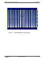
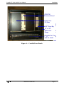
Centellis CT Series 16000 User’s Manual P/N 209298 Edition B July 1998 FORCE COMPUTERS Inc./GmbH All Rights Reserved This document shall not be duplicated, nor its contents used for any purpose, unless express permission has been granted. Copyright by FORCE COMPUTERS World Wide Web: www.forcecomputers.com Headquarters The Americas Europe Asia FORCE COMPUTERS Inc. 2001 Logic Drive San Jose, CA 95124-3468 U.S.A. FORCE COMPUTERS GmbH Prof.-Messerschmitt-Str. 1 D-85579 Neubiberg/München Germany Tel.: +1 (408) 369-6000 Fax: +1 (408) 371-3382 Email [email protected] Tel.: +49 (89) 608 14-0 Fax: +49 (89) 609 77 93 Email [email protected] FORCE COMPUTERS Japan KK Miyakeya Building 4F 1-9-12 Hamamatsucho Minato-ku, Tokyo 105 Japan Tel.: +81 (03) 3437 3948 Fax: +81 (03) 3437 3968 Email [email protected] NOTE The information in this document has been carefully checked and is believed to be entirely reliable. FORCE COMPUTERS makes no warranty of any kind with regard to the material in this document, and assumes no responsibility for any errors which may appear in this document. FORCE COMPUTERS reserves the right to make changes without notice to this, or any of its products, to improve reliability, performance, or design. FORCE COMPUTERS assumes no responsibility for the use of any circuitry other than circuitry which is part of a product of FORCE COMPUTERS Inc./GmbH. FORCE COMPUTERS does not convey to the purchaser of the product described herein any license under the patent rights of FORCE COMPUTERS Inc./GmbH nor the rights of others. All product names as mentioned herein are the trademarks or registered trademarks of their respective companies. Table of Contents Using This Manual . . . . . . . . . . . . . . . . . . . . . . . . . . . . . . . . . . . . . . . . . . . . . . . . . . . . . . . . . . . . . . . . vii 1.0 Introduction . . . . . . . . . . . . . . . . . . . . . . . . . . . . . . . . . . . . . . . . . . .1 1.1 General Information . . . . . . . . . . . . . . . . . . . . . . . . . . . . . . . . . . . . . . . . . . . . . . . . . 1 1.2 Manual Overview . . . . . . . . . . . . . . . . . . . . . . . . . . . . . . . . . . . . . . . . . . . . . . . . . . . 1 1.3 General Description . . . . . . . . . . . . . . . . . . . . . . . . . . . . . . . . . . . . . . . . . . . . . . . . . 1 1.4 System Features . . . . . . . . . . . . . . . . . . . . . . . . . . . . . . . . . . . . . . . . . . . . . . . . . . . . 3 1.5 Chassis Modular Components. . . . . . . . . . . . . . . . . . . . . . . . . . . . . . . . . . . . . . . . . . 4 1.6 System Applications . . . . . . . . . . . . . . . . . . . . . . . . . . . . . . . . . . . . . . . . . . . . . . . . . 4 1.7 CompactPCI Backplane Architecture . . . . . . . . . . . . . . . . . . . . . . . . . . . . . . . . . . . . 4 2.0 System Setup and Operation . . . . . . . . . . . . . . . . . . . . . . . . . . . . . .7 2.1 General Information . . . . . . . . . . . . . . . . . . . . . . . . . . . . . . . . . . . . . . . . . . . . . . . . . 7 2.2 Warnings and Safety Information . . . . . . . . . . . . . . . . . . . . . . . . . . . . . . . . . . . . . . . 7 2.3 Pre-Installation Instructions . . . . . . . . . . . . . . . . . . . . . . . . . . . . . . . . . . . . . . . . . . . 8 2.4 Chassis Front Description . . . . . . . . . . . . . . . . . . . . . . . . . . . . . . . . . . . . . . . . . . . . . 8 2.5 Chassis Rear Description . . . . . . . . . . . . . . . . . . . . . . . . . . . . . . . . . . . . . . . . . . . . 10 2.6 Power Controls . . . . . . . . . . . . . . . . . . . . . . . . . . . . . . . . . . . . . . . . . . . . . . . . . . . . 11 2.7 Board Switches . . . . . . . . . . . . . . . . . . . . . . . . . . . . . . . . . . . . . . . . . . . . . . . . . . . . 11 2.8 CompactPCI Slots . . . . . . . . . . . . . . . . . . . . . . . . . . . . . . . . . . . . . . . . . . . . . . . . . . 12 2.9 Integrated Peripheral Tray. . . . . . . . . . . . . . . . . . . . . . . . . . . . . . . . . . . . . . . . . . . . 12 2.10 Power-up Procedures . . . . . . . . . . . . . . . . . . . . . . . . . . . . . . . . . . . . . . . . . . . . . . . 13 2.10.1 Connecting Chassis Peripherals . . . . . . . . . . . . . . . . . . . . . . . . . . . . . . . . . 13 2.10.2 Powering Up . . . . . . . . . . . . . . . . . . . . . . . . . . . . . . . . . . . . . . . . . . . . . . . . 14 2.11 Power Supplies . . . . . . . . . . . . . . . . . . . . . . . . . . . . . . . . . . . . . . . . . . . . . . . . . . . . 14 3.0 Configuration and Connections . . . . . . . . . . . . . . . . . . . . . . . . . . .15 3.1 Chassis Backplane Layout . . . . . . . . . . . . . . . . . . . . . . . . . . . . . . . . . . . . . . . . . . . 15 3.2 Connectors and Pin-outs . . . . . . . . . . . . . . . . . . . . . . . . . . . . . . . . . . . . . . . . . . . . . 15 3.2.1 Serial COM Port Devices . . . . . . . . . . . . . . . . . . . . . . . . . . . . . . . . . . . . . . 16 3.2.2 Ethernet Interface (RJ-45) Connector. . . . . . . . . . . . . . . . . . . . . . . . . . . . . 17 3.2.3 Keyboard Interface Connector . . . . . . . . . . . . . . . . . . . . . . . . . . . . . . . . . . 18 3.2.4 Mouse Port Connector . . . . . . . . . . . . . . . . . . . . . . . . . . . . . . . . . . . . . . . . 19 3.2.5 IEEE 1284 Printer Port Connector . . . . . . . . . . . . . . . . . . . . . . . . . . . . . . . 19 3.2.6 AC Power Connector . . . . . . . . . . . . . . . . . . . . . . . . . . . . . . . . . . . . . . . . . 21 3.2.7 SVGA Video Port Rear-Panel Connector. . . . . . . . . . . . . . . . . . . . . . . . . . 21 3.3 SCSI Connections . . . . . . . . . . . . . . . . . . . . . . . . . . . . . . . . . . . . . . . . . . . . . . . . . . 22 iii Table of Contents 3.3.1 SCSI Bus Cable Length Guidelines . . . . . . . . . . . . . . . . . . . . . . . . . . . . . . 25 3.3.2 SCSI Bus Termination . . . . . . . . . . . . . . . . . . . . . . . . . . . . . . . . . . . . . . . . 25 3.4 CompactPCI Connector Pin Assignments . . . . . . . . . . . . . . . . . . . . . . . . . . . . . . . 25 3.4.1 J1/J2 Backplane CompactPCI Connector . . . . . . . . . . . . . . . . . . . . . . . . . . 25 3.4.2 J3: Backplane I/O Connector . . . . . . . . . . . . . . . . . . . . . . . . . . . . . . . . . . . 27 3.4.3 J4 Backplane I/O Connector . . . . . . . . . . . . . . . . . . . . . . . . . . . . . . . . . . . . 27 3.4.4 J5 Backplane I/O Connector. . . . . . . . . . . . . . . . . . . . . . . . . . . . . . . . . . . . 27 4.0 Rack Mounting . . . . . . . . . . . . . . . . . . . . . . . . . . . . . . . . . . . . . . .29 4.1 Chassis Installation . . . . . . . . . . . . . . . . . . . . . . . . . . . . . . . . . . . . . . . . . . . . . . . . . 29 4.2 Ventilation and Airflow. . . . . . . . . . . . . . . . . . . . . . . . . . . . . . . . . . . . . . . . . . . . . . 29 5.0 Requirements and Specifications. . . . . . . . . . . . . . . . . . . . . . . . . .31 5.1 Chassis Identication . . . . . . . . . . . . . . . . . . . . . . . . . . . . . . . . . . . . . . . . . . . . . . . . 31 5.2 Power Requirements . . . . . . . . . . . . . . . . . . . . . . . . . . . . . . . . . . . . . . . . . . . . . . . . 31 5.2.1 Power Supplies . . . . . . . . . . . . . . . . . . . . . . . . . . . . . . . . . . . . . . . . . . . . . . 31 5.2.2 Peripheral Tray Modules. . . . . . . . . . . . . . . . . . . . . . . . . . . . . . . . . . . . . . . 32 5.3 Mechanical Specifications . . . . . . . . . . . . . . . . . . . . . . . . . . . . . . . . . . . . . . . . . . . 32 5.4 Environmental Requirements . . . . . . . . . . . . . . . . . . . . . . . . . . . . . . . . . . . . . . . . . 32 5.5 Safety and Emissions Certification . . . . . . . . . . . . . . . . . . . . . . . . . . . . . . . . . . . . . 33 Product Error Report iv List of Figures Figure Figure Figure Figure Figure Figure Figure Figure Figure Figure Figure Figure Figure Figure 1: 2: 3: 4: 5: 6: 7: 8: 9: 10: 11: 12: 13: 14: Centellis Internal Modules (Chassis Front View) . . . . . . . . . . . . . . . . . . . . . . . . . . . 2 Centellis Internal Modules (Chassis Rear View). . . . . . . . . . . . . . . . . . . . . . . . . . . . 2 Centellis Backplane Layout Drawing . . . . . . . . . . . . . . . . . . . . . . . . . . . . . . . . . . . . 5 Centellis Front Panels . . . . . . . . . . . . . . . . . . . . . . . . . . . . . . . . . . . . . . . . . . . . . . . . 9 Centellis Back Panels. . . . . . . . . . . . . . . . . . . . . . . . . . . . . . . . . . . . . . . . . . . . . . . . 10 Chassis Power Controls (Lower Left, Rear) . . . . . . . . . . . . . . . . . . . . . . . . . . . . . . 11 Serial COM Connector and Pins . . . . . . . . . . . . . . . . . . . . . . . . . . . . . . . . . . . . . . . 16 Ethernet Interface (RJ-45) Connector Pin-out . . . . . . . . . . . . . . . . . . . . . . . . . . . . . 17 Keyboard Interface Connector Pin-out . . . . . . . . . . . . . . . . . . . . . . . . . . . . . . . . . . 18 Mouse Port Connector Pin-out . . . . . . . . . . . . . . . . . . . . . . . . . . . . . . . . . . . . . . . . 19 LPT1 IEEE 1284 Printer Port Connector Pin-out . . . . . . . . . . . . . . . . . . . . . . . . . . 20 AC Power Connector . . . . . . . . . . . . . . . . . . . . . . . . . . . . . . . . . . . . . . . . . . . . . . . . 21 Video Graphics . . . . . . . . . . . . . . . . . . . . . . . . . . . . . . . . . . . . . . . . . . . . . . . . . . . . 21 Wide SCSI Rear-Panel Connector. . . . . . . . . . . . . . . . . . . . . . . . . . . . . . . . . . . . . . 22 List of Tables Table Table Table Table Table Table Table Table Table Table Table Table Table Table Table Table Table Table 1: 2: 3: 4: 5: 6: 7: 8: 9: 10: 11: 12: 13: 14: 15: 16: 18: 17: Peripheral Tray Disk Drive Combinations . . . . . . . . . . . . . . . . . . . . . . . . . . . . . . . 12 Centellis CT Series 16000 System Connectors . . . . . . . . . . . . . . . . . . . . . . . . . . . . 15 Rear COM1 & COM2 Serial Connector . . . . . . . . . . . . . . . . . . . . . . . . . . . . . . . . . 16 Ethernet Interface (RJ-45) . . . . . . . . . . . . . . . . . . . . . . . . . . . . . . . . . . . . . . . . . . . . 17 PS/2 Keyboard Interface . . . . . . . . . . . . . . . . . . . . . . . . . . . . . . . . . . . . . . . . . . . . . 18 PS/2 Mouse Interface. . . . . . . . . . . . . . . . . . . . . . . . . . . . . . . . . . . . . . . . . . . . . . . . 19 LPT1 IEEE 1284 Printer Port Interface . . . . . . . . . . . . . . . . . . . . . . . . . . . . . . . . . . 20 AC Power Connector . . . . . . . . . . . . . . . . . . . . . . . . . . . . . . . . . . . . . . . . . . . . . . . . 21 SVGA Video Interface. . . . . . . . . . . . . . . . . . . . . . . . . . . . . . . . . . . . . . . . . . . . . . . 22 Wide SCSI-2 Pin-out . . . . . . . . . . . . . . . . . . . . . . . . . . . . . . . . . . . . . . . . . . . . . . . . 23 SCSI - Signal Descriptions . . . . . . . . . . . . . . . . . . . . . . . . . . . . . . . . . . . . . . . . . . . 24 J1 CompactPCI Interface . . . . . . . . . . . . . . . . . . . . . . . . . . . . . . . . . . . . . . . . . . . . . 25 J2 CompactPCI Interface . . . . . . . . . . . . . . . . . . . . . . . . . . . . . . . . . . . . . . . . . . . . . 26 J4: CompactPCI Interface . . . . . . . . . . . . . . . . . . . . . . . . . . . . . . . . . . . . . . . . . . . . 27 Power Supplies Specifications. . . . . . . . . . . . . . . . . . . . . . . . . . . . . . . . . . . . . . . . . 32 Power Consumption (Typical Values). . . . . . . . . . . . . . . . . . . . . . . . . . . . . . . . . . . 32 Environmental Conditions . . . . . . . . . . . . . . . . . . . . . . . . . . . . . . . . . . . . . . . . . . . . 33 Physical Specifications . . . . . . . . . . . . . . . . . . . . . . . . . . . . . . . . . . . . . . . . . . . . . . 33 v vi Centellis CT Series 16000 User’s Manual Preface Using This Manual This preface provides information on the standard production and format features of the manual, including its structure, layout conventions, and any related documents. Audience of the Manual This user’s manual is intended for users of the Centellis CT Series 16000 system family. Overview of the Manual This manual provides a comprehensive guide to your Centellis CT Series 16000 system. IMPORTANT Take a moment to examine the manual’s “Table of Contents” to see how this document is structured. This will aid you in the future when looking for specific information. This manual includes: • an introductory overview of the Centellis CT Series 16000 (Section 1, “Introduction”) • installation instructions, detailed information on modules, controls, and system connections, and chassis power-up procedures (Section 2, “System Setup and Operation”) • chassis backplane information, connectors, and pin-out assignments for the Centellis 16000 (Section 3, “Configuration and Connections”) • rack mount installation guidelines (Section 4, “Rack Mounting”) • power requirements and equipment specifications (Section 5, “Requirements and Specifications”) • a copy of the Force Computers Product Error Report. Publication History Revision Date Writer Description AA June 1998 G. A. Osika Pre-release AB July 1998 G. A. Osika First Release Special Message Icons and Notes There are three levels of iconicized notes used in this manual. These notes are described below via typical layout examples. Always read and follow the safety notes whenever they appear in the manual. Failure to follow these instructions can result in personal injury or equipment damage. 20000325 420 000 AB Page vii Preface Centellis CT Series 16000 User’s Manual WARNING Danger: personal injury or equipment damage possible. CAUTION Warning: no danger to people, but equipment damage or loss of data possible. ! IMPORTANT Special Message: important product features, instructions, and user tips and information. Page viii 20000325 420 000 AB Centellis CT Series 16000 User’s Manual Introduction 1.0 Introduction 1.1 General Information The Centellis CT Series 16000 is a CompactPCI, rackmountable system chassis that offers a costeffective CompactPCI environment suitable for the U.S., European, and Asian marketplaces. The chassis’s rugged construction and integral mounting points provide the high quality and versatility necessary for peak product performance. The Centellis CT Series 16000 system chassis accommodates a main processor board (three 6U CompactPCI slots) and supports 14 standard 6U CompactPCI slots in numerous user-implemented I/O configurations. 1.2 Manual Overview This document describes the features and functions of the Centellis CT Series 16000 system chassis. This section (Section 1) includes a brief overview of the hardware (chassis and mechanical modules) and the software applications for the Centellis CT Series 16000. Installation instructions, cautionary notes, and information on how to handle the Centellis CT Series 16000 system chassis are outlined in Section 2 of this manual. Section 3 provides an overview of the chassis layout and a description of the interconnections within the chassis. Section 4 supplies information on rackmounting the chassis. Section 5 provides important safety notes and warnings, product operational and mechanical specifications, and all relevant regulatory agency approvals. 1.3 General Description The Centellis CT Series 16000 is an aluminum chassis designed primarily for mounting in a standard 19- or 23-inch equipment rack. The chassis encases a slotted subchassis containing a 16-slot CompactPCI backplane. The CompactPCI backplane has 14 open 6U slots after the CPU board is installed. The chassis contains an integrated peripheral tray with space for one front-accessible 5-1/4" half-height disk drive and one internal 3-1/2" half-height disk drive. Two 300 watt AC power supplies with individual on/off switches and 110VAC/230VAC voltage switches provide system power. System cooling is handled by a three-fan tray module. The chassis has EMI/RFItight front and rear covers, and rear panel I/O with installed 80mm rear transition boards. Convertible mounting ears are provided for rack mounting. The mounting ears can be attached either flush to the front of the chassis or at a chassis midpoint recess. Figure 1 shows the internal component modules located at the front of the Centellis CT Series 16000 chassis; Figure 2 shows the modules located at the rear of the chassis. 20000325 420 000 AB Page 1 Centellis CT Series 16000 User’s Manual Front 5.25” Introduction 7 6U Expansion Slots 7 6U Expansion Slots Serviceable Fan Module 80mm I/O Expansion 80mm IOBP 80mm I/O Expansion 80mm IOBP Figure 1: Centellis Internal Modules (Chassis Front View) Pending receipt of graphic from Pocheng. Power Input Module 300W PSU J1 300W PSU Rear View Figure 2: Centellis Internal Modules (Chassis Rear View) Page 2 20000325 420 000 AB Centellis CT Series 16000 User’s Manual 1.4 Introduction System Features CompactPCI and the H.110 CT bus, the primary technologies of the Centellis CT Series 16000, provide high-speed performance, manageability, and flexibility for growing telephony applications. Key hardware and software features include: • 16-slot CompactPCI Backplane - Secondary H.110 CT bus - 14 6U I/O expansion slots - Passive (non-active) components - Integrated alarms on power backplane • I/O Connectivity - 80 mm rear I/O transition boards - Configurable front or rear CPU I/O connectivity, including VGAand SCSI • Power Supply - Two rear-serviceable 300W modules - Load sharing (with system power up to 300W) - Hot swappable (with system power less than or equal to 300W) - 110/220 VAC voltage user-selectable - Switched, fused, and filtered AC system input • Chassis - Aluminum chassis - Size: 17" W x 17" D 15.75(9U) H (432 mm x 432 mm x 400 mm) - 19" or 23" equipment rack mounting via chassis mounting ears - Front-flush or midpoint recessed rack mounting • Integrated Peripheral Tray - One front-accessible 5.25" drive bay - One internal 3.5" drive bay • Fan Tray Module - Three 12VDC brushless fans - 110 CFM (cubic feet per minute)/fan (330 CFM total) air draw - Front-to-back cooling airflow - Front-serviceable - No monitoring or sensing 20000325 420 000 AB Page 3 Introduction 1.5 Centellis CT Series 16000 User’s Manual Chassis Modular Components The Centellis CT Series 16000 chassis contains four functional hardware modular components. Each component mounts in or to the Centellis chassis frame. The modular components of a Centellis CT Series 16000 chassis are: • One card cage with a CompactPCI backplane • One serviceable fan tray holding three cooling fans • Two power supply assemblies • One Integrated Peripheral Tray holding two disk drives 1.6 System Applications The Centellis CT Series 16000 system chassis was designed as a CompactPCI platform for a variety of embedded applications. Users can install up to 14 6U CompactPCI boards into the chassis. System chassis configurations can include 3.5" hard disk drives and a CD-ROM drive. Applications for the Centellis CT Series 16000 include: • Telephony applications, including voice and FAX processing • WLL applications for SS7 execution • Firewall applications for data filtering • Other applications with additional intelligent I/O or real-time processing boards 1.7 CompactPCI Backplane Architecture The Centellis CT Series 16000 chassis contains a 16-slot CompactPCI backplane. Two backplane slots for the system CPU subdivide the remaining 6U user I/O expansion slots into two independent 7-slot segments. (Although 17 slots physically exist, a third CPU slot is an inactive "dummy" slot.) Figure 3 shows a sample CPCI backplane layout diagram. The J4 connector on the I/O expansion slots supports an integrated H.110 Computer Telephony bus. This provides the backplane’s time division multiplexing capability. The H.110 bus is wired to slots A1 thru A7 and B10 thru B16. The CPCI backplane is a passive backplane; it holds no active components. Page 4 20000325 420 000 AB 6U Expansion Slot 6U Expansion Slot 6U Expansion Slot 6U Expansion Slot 6U Expansion Slot 6U Expansion Slot 6U Expansion Slot 6U Expansion Slot 6U Expansion Slot 6U Expansion Slot 6U Expansion Slot 6U Expansion Slot 6U Expansion Slot 6U Expansion Slot 6U Expansion Slot 6U Expansion Slot 6U Expansion Slot 6U Expansion Slot 6U Expansion Slot 6U Expansion Slot 6U Expansion Slot 6U Expansion Slot 6U Expansion Slot 6U Expansion Slot 6U Expansion Slot 6U Expansion Slot 6U Expansion Slot 6U Expansion Slot Centellis CT Series 16000 User’s Manual Introduction J5J 5 3-slot CPU board set J4J 4 20000325 420 000 AB J3J 3 J2J 2 J1J 1 Figure 3: Centellis Backplane Layout Drawing Page 5 Introduction Page 6 Centellis CT Series 16000 User’s Manual 20000325 420 000 AB Centellis CT Series 16000 User’s Manual Installation 2.0 System Setup and Operation 2.1 General Information This section describes the set up and usage of the 16000 chassis and its component modules. Included are important warnings and safety notes, pre-installation information, a description of the front and back panels, power supply specifications, power up procedures, and chassis identification information. 2.2 Warnings and Safety Information WARNING This section contains several important check points which must be observed before the chassis is powered on. In addition, warnings and important safety information will be included throughout this manual for specific equipment and operating situations. • Follow all warnings and instructions marked on the equipment. • To allow for sufficient cooling of the card cage slots, do not exceed an 18 watt limit per CompactPCI slot. As to the power consumption of the components used, see the respective technical specifications. Furthermore, make sure that the individual output currents of the separate sources are not exceeded. • Ensure that the CPU card is properly installed between the two seven-slot I/O segments. The board contains special ejectors (the handles). To guarantee proper installation, the board must be plugged in, the handles on the front panel firmly locked, and all screws must be tightened to the card cage. • Adequate space must always exist around the fans and the air inlets and outlets for successful airflow. Insufficient cooling may cause the system to crash and result in serious hardware damage. • This equipment generates, uses and can radiate radio frequency energy. If not installed correctly and used in accordance with the instruction manual, it may cause interference to radio communications. It has been tested and found to comply with the limits of a Class A computing device pursuant to Subpart B of Part 15 of FCC Rules. When operating the system when not in compliance with these instructions and rules, or in the case of interference from radio stations, the user will be required to take whatever measures (e.g. EMI measurements) necessary to correct the disturbances at the user’s expense. • Use ferrite bead on the following cables: parallel, serial, Ethernet, mouse, and keyboard. Wind the cable around the ferrite bead one full turn. • FORCE COMPUTERS, Inc. is not responsible for regulatory compliance or malfunction of any user-modified product. 20000325 420 000 AB Page 7 Installation Centellis CT Series 16000 User’s Manual CAUTION ESD PRECAUTIONS - Static Destroys Products ! • 2.3 The chassis contains static-sensitive devices. Good static control procedures should be used when installing, removing, and handling all components. Use an antistatic wrist strap at all times. Never touch the board components with any conductive objects. Pre-Installation Instructions Upon receipt of your Centellis CT Series 16000 system, check the attached packing slip to verify that the equipment that was ordered was correctly shipped and received in full. Contact Force Computers if any discrepancy exists among the original purchase order, the packing slip, and the received equipment. Visually inspect the product for any physical damage. The product was shipped from Force Computers manufacturing in working condition; any product damage must be immediately reported to the shipping agent. Save the shipping carton and enclosed packing material in case the system must be reshipped in the future. 2.4 Chassis Front Description The Centellis chassis is shipped with two 7-slot 6U front panels that cover the 14 user I/O expansion slots. An installed CPCI-723 module separates the panels into two 7-slot CPCI segments. Use a small Phillips screwdriver to remove the panels. An installed peripheral tray panel for a 5.25" drive bay fills the far right end of the chassis. A pluggable fan tray panel with air intake grillwork is attached to the bottom of the chassis via thumb screws. Figure 4 shows the external front panels of the Centellis chassis. Page 8 20000325 420 000 AB Centellis CT Series 16000 User’s Manual Installation CPCI-720 Processor Board 14 6U User I/O Slots CPCI-720 5.25” Drive BayProcessor Board 19” or 23” Rackmount Flange 14 6U User I/O Slots Pluggable Fan Tray 5.25” Drive Bay with Air Intake 19” or 23” Rackmount Figure 4: Centellis Front Panels 20000325 420 000 AB Page 9 Installation 2.5 Centellis CT Series 16000 User’s Manual Chassis Rear Description The back of the Centellis 16000 chassis contains two seven-slot user I/O segments, two 80mm transition boards, two hot swappable power supplies, and a power connector (with chassis On/Off and AC switches). Figure 5 shows the rear of the chassis and the rear-accessible modules. Top rear air exhaust 16 slot Compact PCI backplane AC Switch Pluggable PSU 80mm transition module Figure 5: Centellis Back Panels Page 10 20000325 420 000 AB Centellis CT Series 16000 User’s Manual 2.6 Installation Power Controls The Centellis CT Series 16000 chassis has one AC input power connector and an on/off power switch located at the lower left back of the chassis. The “ ” symbol at the top of the green switch indicates the on position; the “ O ” on the bottom half of the switch indicates the off position. Two user-replaceable 7A fuses are provided to the left of the power switch. The unit’s power cord is detachable. See Figure 6 for an illustration of these controls. Input voltage for the two AC power supplies is selectable via external slide switches. On/Off Switch Fuses Power Connector Figure 6: Chassis Power Controls (Lower Left, Rear) IMPORTANT The socket outlet that the system is connected to must be installed near the equipment and readily accessible. 2.7 Board Switches The switches of installed boards are always accessible from the front of the chassis. Consult the appropriate CPU board hardware user’s manual to adjust the board switches. CAUTION ! With the exception of lithium batteries installed on a board in this system, the Centellis system is designed to be maintenance-free. The lithium battery in the RTC/NVRAM provides a data retention capability of ten years (actual battery use); after this usage period, the Ethernet address, the host ID address, and all other RTC/NVRAM contents may be lost. Contact Force Computers before ten years of actual battery use have elapsed. There is a danger of explosion if the battery is incorrectly replaced. Replace the 20000325 420 000 AB Page 11 Installation Centellis CT Series 16000 User’s Manual battery only with the same or an equivalent type recommended by the manufacturer. Dispose of used batteries according to the manufacturer’s instructions. Force Computers strongly suggests that only authorized service personnel exchange the RTC/NVRAM and the lithium battery. 2.8 CompactPCI Slots CompactPCI boards can be installed in or removed from the system chassis after one or both of the 7-slot 6U front panels are removed. If all seven slots in a segment are not occupied by CPCI boards, however, a 6U blank panel (with EMI gasket) must be installed in each unoccupied slot. All slots of the chassis must be either occupied by a board or closed off with a covering panel to maintain the EMI integrity of the system. The chassis holds up to fourteen CPCI 6U boards. 2.9 Integrated Peripheral Tray The chassis contains an integrated peripheral tray that holds one external (front-accessible) 5.25" half-height disk drive and one internal 3.5" disk drive. The 5.25" disk drive bay normally holds a CD-ROM drive (SCSI or IDE), but it can be used for a tape backup device. The 3.5" disk drive bay accommodates either a SCSI or IDE 3.5" hard disk drive. There are eight possible combinations of SCSI and IDE CD-ROM and hard disk drives that can be installed in the peripheral tray. Table 1 shows these different combinations. Table 1: Peripheral Tray Disk Drive Combinations CD-ROM Drive Hard Disk Drive IDE SCSI (Narrow) IDE SCSI (Wide) IDE IDE SCSI (Narrow) SCSI (Narrow) SCSI (Narrow) IDE SCSI (Narrow) SCSI (Wide) IDE none SCSI (Narrow) none none* none * If none, use the EMI cover plate. To install either a 5.25" CD-ROM or a 3.5" hard disk drive in the peripheral tray: 1. Unscrew the two thumb screws on the face plate of the peripheral tray, and pull the tray out of the chassis. 2. Install the CD-ROM or the hard disk drive to the peripheral tray. Page 12 20000325 420 000 AB Centellis CT Series 16000 User’s Manual Installation • For hard disk drives, mount the drive onto the HDD mounting bracket with a 6/32" x 1/4" Phillips pan head screw, a #6 split lock washer, and a #6 flat washer at each of the four positions. Do not mount this assembly to the peripheral tray yet; OR • For CD-ROM drives, align the four mounting screw holes on the peripheral tray and the CD-ROM. Attach the drive to the peripheral tray with four 3cm x 6cm pan head screws, four M3 split lock washers, and four M3 flat washers. 3. Attach one end of the flat ribbon cable (the end with two connectors close to each other) and one end of the power cable to the CD-ROM or hard disk drive. 4. For a hard disk drive, attach the completed drive/HDD mounting bracket assemblage to the peripheral tray with four 6/32" x 1/4' flat head screws. 5. Reinsert the peripheral tray with the attached drive(s) back into the chassis. 6. Remove the left rear panel, and attach the other end of the flat ribbon cable to the I/O boards. Route the cables together as directly as possible to avoid cable damage and to save space for other cables and boards. CAUTION: Pin 1 of the flat ribbon cable (red stripe) MUST match with Pin 1 of the connector. 7. Retighten the two thumb screws on the tray face plate to secure the tray to the chassis. 2.10 Power-up Procedures This section explains how to connect chassis peripherals and power up the Centellis chassis. Note the following CAUTION statements before powering up the unit. CAUTION ! Connections between peripherals of the computer equipment must be made with lowvoltage, shielded computer data cables. CAUTION ! Do not attach like devices to both the front CPU panel and the rear chassis panel as damage to components may result. The Centellis 16000 has CPU board connectors at the front of the chassis as well as I/O connectors on the chassis back. 2.10.1 Connecting Chassis Peripherals Peripheral components can be connected to the Centellis chassis at the CPU board in the front of the chassis, or at the transitional board (if installed) at the back of the chassis. Install the peripherals in the following order: 1. Connect an IBM PS/2-style keyboard into the keyboard connection. 2. Connect a PS/2-style mouse into the mouse connection. 3. If installing an optional SVGA compatible monitor, both the monitor and the Centellis chassis must be turned off. Connect the video cable to the video port connection. 20000325 420 000 AB Page 13 Installation Centellis CT Series 16000 User’s Manual 2.10.2 Powering Up 1. Connect the power cable to the AC connector. 2. Turn on each power supply switch. (This is the black switch on each power supply.) 3. Turn on the green power switch at the back of the chassis. After a few seconds, a message will appear on the connected monitor. 4. Check that the fans work properly and that the LEDs on the boards, if available, indicate the run status. 5. To boot the installed operating system, see the operating system’s user’s manual. 2.11 Power Supplies The Centellis CT Series 16000 chassis contains two 300W load-sharing power supplies. The power supplies are installed at the bottom rear side of the chassis. A green LED on the face of each power supply lights when a power supply is in use and functioning properly. If either of the power supplies is malfunctioning, an audible beep will sound from the chassis combiner board. (The green LED on the bad power supply will not light.) This alarm continues until the bad power supply is replaced by a new, working power supply. Ensure that the replacement power supply’s power switch is turned to the On position; if not, the alarm beep will continue. A fifteen-prong connector on the back of the power supply connects to the chassis backplane. See the Centellis Power Supply Installation Instructions (P/N 209652) for complete information on installing and removing the power supplies. CAUTION ! The power supplies are provided with input voltage selector switches. These switches must be set to the correct voltage for your voltage source (115V or 230V). Ensure that each power supply is set to the correct voltage. WARNING The power supplies must be serviced only by service personnel familiar with the hazards and dangers associated with switched mode power supplies. Page 14 20000325 420 000 AB Centellis CT Series 16000 User’s Manual Chassis Layout and Interconnection 3.0 Configuration and Connections The Centellis CT Series 16000 is a CompactPCI-based system chassis designed for CompactPCI in an industrial environment. The 16000’s modularity ensures easy operation, flexibility, and easy rack mounting. All module interconnections in the system are made via standard connectors. The Centellis chassis contains the following modules: • Backplane and Card Cage The Centellis CT Series 16000 chassis contains a backplane which supports up to fourteen 6U CompactPCI slots and a double-slot CPU board. • Power Supplies The chassis is powered by two, rear-accessible 300-watt AC power supplies. • Integrated Peripheral Tray The chassis contains an integrated peripheral tray that holds one 3.5" disk drive bay (for SCSI or EIDE hard disk drives) and one front-accessible 5.25" CD-ROM disk drive bay. • Fan Tray Module There are three brushless DC fans for the chassis unit, and an additional cooling fan in each power supply. 3.1 Chassis Backplane Layout The layered backplane for CompactPCI has continuous ground and power planes. The Centellis 16000 chassis backplane has inboard termination. Refer to CPCI Specification PICMG 2.0 D2.13 (April 14, 1997) for detailed information. 3.2 Connectors and Pin-outs The Centellis CT Series 16000 chassis has a CPU card with both front panel connectors and rear I/O connectors. Table 2 lists the type of connectors located at both the front and rear of the chassis. Table 2: Centellis CT Series 16000 System Connectors Function Quantity Type Serial I/O Com 1 1 9-pin Ethernet (ENET 1) 1 RJ-45 Printer Port IEEE 1284 1 25-pin D-shell Video (SVGA) 1 15-pin PS/2 Mouse 1 PS/2 PS/2 Keyboard 1 PS/2 * A Serial I/O Com 2 connector is located at the rear of the chassis only. 20000325 420 000 AB Page 15 Chassis Layout and Interconnection 3.2.1 Centellis CT Series 16000 User’s Manual Serial COM Port Devices There are two serial com ports: Com 1 and Com 2. Com 1 is located on the front and rear panels of the Centellis chassis, while Com 2 is only found on the chasis rear. Serial devices that may be attached to these ports include printers, terminals, and modems. Figure 7 shows the pin configuration of the COM ports. Table 3 provides the function and signal type of each COM port connector pin. CAUTION ! Simultaneously using both the front and rear panel I/O connectors may cause system damage. Com 1 and Com 2 1 2 3 4 5 6 7 8 9 Figure 7: Serial COM Connector and Pins Table 3: Rear COM1 & COM2 Serial Connector Page 16 Pin Function Descriptions 1 DCD Data Carrier Detect 2 RxD Receive Data 3 TxD Transmit Data 4 DTR Data Terminal Ready 5 GND Ground 6 DSR Data Send Ready 7 RTS Request to Send 8 CTS Clear to Send 9 RIN Ring Indicator 20000325 420 000 AB Centellis CT Series 16000 User’s Manual 3.2.2 Chassis Layout and Interconnection Ethernet Interface (RJ-45) Connector The Ethernet Interface, an RJ-45 connector, provides both 10 Mbit (10Base-T) and 100 Mbit (100Base-TX) protocols. The Ethernet interface uses autosensing circuitry to switch between 10 Mbit and 100 Mbit operation. The connector pin-out is shown in figure 8, and the pin functions and signals are provided in Table 4. The connector also incorporates a yellow LED for data packet transfer and a green LED for indication of network packet traffic. A bi-color status LED on the front panel indicates 10 Mbit operation (Green) or 100 Mbit operation (Red). ENET1 1 2 34 5 6 7 8 Figure 8: Ethernet Interface (RJ-45) Connector Pin-out Table 4: Ethernet Interface (RJ-45) Pin Function Signal 1 TX+ Transmit Data+ 2 TX- Transmit Data- 3 RX+ Receive Data+ 4 GND Ground 5 GND Ground 6 RX- Receive Data- 7 GND Ground 8 GND Ground 20000325 420 000 AB Page 17 Chassis Layout and Interconnection 3.2.3 Centellis CT Series 16000 User’s Manual Keyboard Interface Connector The Keyboard Interface allows interfacing to standard PS/2-style keyboard devices. The connector pin-outs are shown in Figure 9, and the pin functions are provided in Table 5. Keyboard connectors are located on the front and the rear panel of the chassis. CAUTION ! Using both the front-panel and rear-panel I/O connectors simultaneously may cause system damage. 5 6 3 4 1 2 Figure 9: Keyboard Interface Connector Pin-out Table 5: PS/2 Keyboard Interface Pin Page 18 Function 1 KBDAT 2 No Connect 3 GND 4 Vcc (Fused) 5 KBCLK 6 No Connect 20000325 420 000 AB Centellis CT Series 16000 User’s Manual 3.2.4 Chassis Layout and Interconnection Mouse Port Connector The Mouse Port Interface allows the hookup of PS/2-style mouse devices. The connector pin-outs are shown in Figure 10, and the pin functions are provided in Table 6. Mouse connectors are located on the front and read panels of the chassis. CAUTION ! Using both the front-panel and rear-panel I/O connectors simultaneously may cause system damage. 5 6 3 4 1 2 Figure 10: Mouse Port Connector Pin-out Table 6: PS/2 Mouse Interface Pin 3.2.5 Function 1 MSDAT 2 No Connect 3 GND 4 Vcc (Fused) 5 MSCLK 6 No Connect IEEE 1284 Printer Port Connector The IEEE 1284 printer port allows interfacing to standard printer functions. The connector adheres to the IEEE 1284-C specification. The connector pin-outs are shown in Table 7. AMP manufactures cable assemblies for interfacing between an IEEE-1284C connector and older Type 20000325 420 000 AB Page 19 Chassis Layout and Interconnection Centellis CT Series 16000 User’s Manual A (Centronics) and Type B (25-pin D-shell) printer connectors. Printer ports are located on the front and rear panels of the 16000 chassis. CAUTION ! Using both the front-panel and rear-panel I/O connectors simultaneously may cause system damage. .. . .. . 18 .. . .. . 36 1 19 Figure 11: LPT1 IEEE 1284 Printer Port Connector Pin-out Table 7: LPT1 IEEE 1284 Printer Port Interface Pin Page 20 Function Pin Function 1 BUSY 19 GND 2 SLCT 20 GND 3 ACK- 21 GND 4 ERR- 22 GND 5 PE 23 GND 6 PPD0 24 GND 7 PPD1 25 GND 8 PPD2 26 GND 9 PPD3 27 GND 10 PPD4 28 GND 11 PPD5 29 GND 12 PPD6 30 GND 13 PPD7 31 GND 14 INIT- 32 GND 15 STB- 33 GND 16 SLIN- 34 GND 17 AFD- 35 GND 18 HLD 36 PLH 20000325 420 000 AB Centellis CT Series 16000 User’s Manual 3.2.6 Chassis Layout and Interconnection AC Power Connector Figure 12 illustrates the chassis AC power connector located at the lower left rear of the chassis. Table 8 identifies the function of each power plug connector pin. 1 2 3 Figure 12: AC Power Connector Table 8: AC Power Connector Pin 3.2.7 Function 1 Neutral 2 Line 3 Chassis Ground SVGA Video Port Rear-Panel Connector The SVGA video port is only functional with the optional video card. Figure 13 and Table 9 provide pinout information for the video port. 10 5 15 .. . .. . 11 1 6 Figure 13: Video Graphics 20000325 420 000 AB Page 21 Chassis Layout and Interconnection Centellis CT Series 16000 User’s Manual Table 9: SVGA Video Interface Pin 3.3 Function 1 Red 2 Green 3 Blue 4 Not Used 5 Ground 6 Red Return 7 Green Return 8 Blue Return 9 Key 10 Ground 11 Not Used 12 Not Used 13 Horiz. Sync. 14 Vert. Sync. 15 Not Used SCSI Connections SCSI allows the connection of the system unit to external storage units, such as hard disks, cartridge tapes, and compact disk drives. The Centellis CT Series 16000 chassis has a wide SCSI-2 connector (see Figure 14) on the rear panel. IMPORTANT When using wide SCSI devices, the WIDE* signal must be connected to ground. This signal is available on BP-J5B at pin-17 as illustrated in the section on alarm support for setting alarm priorities in the CPU-720 Technical Manual. .. . .. . 68 .. . .. . 34 1 35 Figure 14: Wide SCSI Rear-Panel Connector Page 22 20000325 420 000 AB Centellis CT Series 16000 User’s Manual Chassis Layout and Interconnection Table 10: Wide SCSI-2 Pin-out Pin Number Signal Name Pin Number Signal Name 1 Ground 35 SCD12* 2 Ground 36 SCD13* 3 Ground 37 SCD14* 4 Ground 38 SCD15* 5 Ground 39 SCDPH* 6 Ground 40 SCD0* 7 Ground 41 SCD1* 8 Ground 42 SCD2* 9 Ground 43 SCD3* 10 Ground 44 SCD4* 11 Ground 45 SCD5* 12 Ground 46 SCD6* 13 Ground 47 SCD7* 14 Ground 48 SCDPL* 15 Ground 49 Ground 16 Ground 50 WIDE 17 TERMPWR 51 TERMPWR 18 TERMPWR 52 TERMPWR 19 Ground 53 Ground 20 Ground 54 Ground 21 Ground 55 ATN* 22 Ground 56 Ground 23 Ground 57 BSY* 24 Ground 58 SACK* 25 Ground 59 SRST* 26 Ground 60 MSG* 27 Ground 61 SEL* 20000325 420 000 AB Page 23 Chassis Layout and Interconnection Centellis CT Series 16000 User’s Manual Table 10: Wide SCSI-2 Pin-out 28 Ground 62 CD* 29 Ground 63 SREQ* 30 Ground 64 IO* 31 Ground 65 SCD8* 32 Ground 66 SCD9* 33 Ground 67 SCD10* 34 Ground 68 SCD11* Table 11: SCSI - Signal Descriptions Page 24 Signal Descriptions scd<0-15> SCSI Data Bits 0 to 15 scdph* SCSI Data Parity atn* Attention bsy* Busy sack* Acknowledge srst* Reset msg* Message sel* Select cd* Control/Data sreq* Request io* Input/Output Termpwr Termination Voltage WIDE Wide SCSI mode 20000325 420 000 AB Centellis CT Series 16000 User’s Manual 3.3.1 Chassis Layout and Interconnection SCSI Bus Cable Length Guidelines The SCSI standard sets a maximum of 6.0 meters total length for all SCSI signals. The internal SCSI bus length on the Centellis system chassis is 0.68 meters maximum. For specific information about installing SCSI devices consult the manual that comes with the device. 3.3.2 SCSI Bus Termination The Centellis CT Series 16000 system chassis automatically terminates the SCSI bus. This termination response can be overridden if a cable is plugged into the chassis rear connector. Users must supply termination on the SCSI segments external to the 16000. 3.4 CompactPCI Connector Pin Assignments The CompactPCI bus is designed for 5V and 3.3V operation. Centellis CT Series 16000 chassis are preset for 5V operation. 3.4.1 J1/J2 Backplane CompactPCI Connector The J1 and J2 connectors, combined, provide a 220-pin 2 mm x 2 mm female connector for the CompactPCI backplane interface. Blue keying is used on J1 to indicate 5V operation. Tables 12 and 13 provide the signal type of each J1 and J2 interface pin. Table 12: J1 CompactPCI Interface PIN 25 24 23 22 21 20 19 18 17 16 15 14 13 12 11 10 9 8 7 6 5 4 3 2 1 Z GND GND GND GND GND GND GND GND GND GND GND KEY KEY KEY GND GND GND GND GND GND GND GND GND GND GND A 5V AD(1) 3.3V AD(7) 3.3V AD(12) 3.3V SERR# 3.3V DEVSEL# 3.3V KEY KEY KEY AD(18) AD(21) C/BE(3)# AD(26) AD(30) REQ# BRSV(B10) BRSV(A9) INTA# TCK 5V B REQ64# 5V AD(4) GND AD(9) GND AD(15) GND SDONE GND FRAME# KEY KEY KEY AD(17) GND IDSEL GND AD(29) GND BRSV(A11) GND INTB# 5V -12V C ENUM V(I/O) AD(3) 3.3V AD(8) V(I/O) AD(14) 3.3V SBO# V(I/O) IRDY# KEY KEY KEY AD(16) 3.3V AD(23) V(I/O) AD(28) 3.3V RST# V(I/O) INTC# TMS TRST# D 3.3V AD(O) 5V AD(6) M66EN AD(11) GND PAR GND STOP# GND KEY KEY KEY GND AD(20) GND AD(25) GND CLK GND INTP 5V TDO +12V 20000325 420 000 AB E 5V ACK64# AD(2) AD(5) C/BE(0)# AD(10) AD(13) C/BE(1)# PERR# LOCK# TRDY# KEY KEY KEY C/BE(2)# AD(19) AD(22) AD(24) AD(27) AD(31) GNT# INTS INTD# TDI 5V F GND GND GND GND GND GND GND GND GND GND GND KEY KEY KEY GND GND GND GND GND GND GND GND GND GND GND Page 25 Chassis Layout and Interconnection Centellis CT Series 16000 User’s Manual Table 13: J2 CompactPCI Interface PIN 22 21 20 19 18 17 16 15 14 13 12 11 10 9 8 7 6 5 4 3 2 1 Z A B C D E F GND GND GND GND GND GND GND GND GND GND GND GND GND GND GND GND GND GND GND GND GND GND RSV RSV RSV RSV BRSV(B92) BRSV(A92) BRSV(A19) BRSV(A14) AD[35] AD[38] AD[42] AD[45] AD[49] AD[52] AD[56] AD[59] AD[63] C/BE[5] V(I/0) INTA# TCK 5V RSV GND RSV GND BRSV(A94) GND BRSV(B93) GND AD[34] GND AD[41] GND AD[48] GND AD[55] GND AD[62] GND BRSVB4 INTB# 5V -12V RSV RSV RSV RSV BRSVC18 PRST# DEG# FAL# AD[33] V(I/0) AD[40] V(I/0) AD[47] V(I/0) AD[54] V(I/0) AD[61] V(I/0) C/BE[7] INTC# TMS TRST# RSV RSV GND RSV GND REQ6# GND REQ5# GND AD[37] GND AD[44] GND AD[51] GND AD[58] GND C/BE[4]# GND 5V TDO +12V RSV RSV RSV RSV BRSVE18 GNT6# BRSVE16 GNT5#(8) AD[32] AD[36] AD[39] AD[43] AD[46] AD[50] AD[53] AD[57] AD[60] PAR64 C/BE[6] INTD# TDI 5V GND GND GND GND GND GND GND GND GND GND GND GND GND GND GND GND GND GND GND GND GND GND Notes: V(I/O) are 5V NC = Not Connected Page 26 20000325 420 000 AB Centellis CT Series 16000 User’s Manual 3.4.2 Chassis Layout and Interconnection J3: Backplane I/O Connector J3 is a user-defined I/O connector on the Centellis backplane. For pin-out information, consult the appropriate CompactPCI PICMG specifications. 3.4.3 J4 Backplane I/O Connector The J4 connector is used for the H.110 bus. This connector is a 220-pin 2 mm x 2 mm female connector for a 2mm interface. Red keying is used on J4. Table 14: J4: CompactPCI Interface Pin Row Z Row A 25 Not Used SGA4 M SGA3 Row B M SGA2 Row C M SGA1 Row D M SGA0 Row E M FG Row F L 24 " GA4 M GA3 M GA2 M GA1 M GA0 M FG L 23 " +12V M /CT_Reset M /CT_EN S -12V M CT_MC M FG L 22 " RSVD M RSVD M RSVD M RSVD M RSVD M FG L L RSVD M RSVD M RSVD M -SELVbatRtn L FG L 21 " -SELVbat 20 " Not Used 19 " Not Used 18 " VRG M Not Used Not Used Not Used Not Used Not Used Not Used Not Used Not Used Not Used Not Used Not Used Not Used 17 " Not Used Not Used Not Used Not Used Not Used 16 " Not Used Not Used Not Used Not Used Not Used 15 " -Vbat Not Used Not Used Not Used Not Used L NP NP M NP NP NP L NP 14 KEY AREA (keep unobstructed on backplane to ease routing constraints) 13 12 11 " CT_D29 M CT_D30 M CT_D31 M V(I/O) L /CT_FRAME_A M GND L 10 " CT_D27 M +3.3V M CT_D28 M +5V L /CT_FRAME_B M GND L 9 " CT_D24 M CT_D25 M CT_D26 M GND L /FR_COMP M GND L 8 " CT_D21 M CT_D22 M CT_D23 M +5V L CT_C8_A M GND L 7 " CT_D19 M +5V M CT_D20 M GND L CT_C8_A M GND L 6 " CT_D16 M CT_D17 M CT_D18 M GND L CT_NETREF_1 M GND L 5 " CT_D13 M CT_D14 M CT_D15 M +3.3V L CT_NETREF_2 M GND L 4 " CT_D11 M +5V M CT_D12 M +3.3V L SCLK M GND L 3 " CT_D8 M CT_D9 M CT_D10 M GND L SCLKx2 M GND L 2 " CT_D4 M CT_D5 M CT_D6 M CT_D7 M GND L GND L 1 " CT_D0 M +3.3V M CT_D1 M CT_D2 M CT_D3 M GND L 3.4.4 J5 Backplane I/O Connector. J5 is a user-defined I/O connector on the Centellis backplane. For pin-out information, consult the appropriate CompactPCI PICMG specifications. 20000325 420 000 AB Page 27 Chassis Layout and Interconnection Page 28 Centellis CT Series 16000 User’s Manual 20000325 420 000 AB Centellis CT Series 16000 User’s Manual Rack Mounting 4.0 Rack Mounting 4.1 Chassis Installation To install the Centellis CT Series 16000 chassis in a standard 19-inch or 23-inch equipment rack: • Remove the two filler plates on the left and right sides of the front of the chassis. • Attach the mounting bracket ears with a Phillips head screwdriver and screws on each side of the chassis. WARNING 4.2 To prevent bodily injury when mounting or servicing this unit in a rack, you must take special precautions to ensure that the system remains stable. The following guidelines are provided to ensure your safety: • This unit should be mounted at the bottom of the rack if it is the only unit in the rack. • When mounting the unit in a partially filled rack, use the lowest available open space in the rack. Always load the rack from the bottom to the top with the heaviest components at the bottom of the rack. • If the rack is provided with stabilizing devices, install the stabilizers before mounting or servicing the unit in the rack. Ventilation and Airflow Three throughput fans in the Centellis CT Series 16000, and a fan on each power supply, provide optimal chassis airflow. Adequate space must always exist around the fans and the air inlets and outlets for successful airflow. Allow at least 3-1/2" at the front and back of the chassis, and do not cover the side vents. FORCE COMPUTERS 20000325 420 000 AB 15172101 420 000 AAPage 29 Page 29 Rack Mounting Page 30 Centellis CT Series 16000 User’s Manual 20000325 420 000 AB FORCE COMPUTERS Centellis CT Series 16000 User’s Manual Specifications 5.0 Requirements and Specifications 5.1 Chassis Identication A system chassis identification label is attached to the lower right side of the chassis. The label provides the following chassis information: • • • • • 5.2 Serial number (bar coded) System name Operating voltage Operating voltage frequency Country of manufacture (origin) Power Requirements Power requirements and specifications for the power supplies and the integrated peripheral tray of the Centellis CT Series 16000 are provided in Tables 15 and 16. 5.2.1 Power Supplies Table 15 provides complete operating and voltage specifications for the 300W power supplies used in the Centellis CT Series 16000 chassis. Table 15: Power Supplies Specifications Input Voltage: 115/230 VAC single phase Input Frequency: 50/60 Hz Input Current: 230V AC: IE = 3A 115V AC: IE = 6A Output Power 300 Watts @ 43°C ambient temperature Output Voltage: DC Output Voltage +3.3 V @ 20A, +5.0V @ 30A +12 V @ 15A, -12V @ 1.5A Efficiency: >74% to 78% (5V) Output Protection: Current limit protection 105% to 150% rated output OVP for 3.3V @3.8V to 4.8V, and for 5V @ 5.6V to 7.0V M.T.B.F.: 65,000 hours Safety: UL 1950, CAN/CSA C22.2 No. 950-95, EN60950 EMI EN55022 Class A, FCC Rules Part 15 Subpart B Class A 20000325 420 000 AB Page 31 Specifications 5.2.2 Centellis CT Series 16000 User’s Manual Peripheral Tray Modules Table 16 provides power consumption values for the peripheral tray modules. Table 16: Power Consumption (Typical Values) 5.3 Device +5V +12V -12V +3.3 Hard Disk Drive 500 mA 1.2 A N/A N/A CD-ROM 400 mA 1.8 A N/A N/A Floppy Disk Drive 700 mA N/A N/A N/A Mechanical Specifications Table 17 provides physical data on the Centellis chassis. The weight of the unit is for the base configuration (including power supplies, disk drives, and mounting brackets) but DOES NOT include the weight of any user-installed I/O boards.. Table 17: Physical Specifications Specification Value Dimensions: Width x Depth x Height 17 x 17 x 15.75 inches (43.2 x 43.2 x 40 centimeters) NOTE: Width does not include 2 inches (5.1 centimeters) for two mounting brackets Weight: 5.4 50 pounds (22.7 kilograms) Environmental Requirements Table 18 lists the tested environmental conditions for the Centellis CT Series 16000 chassis. Table 18: Environmental Conditions Page 32 Vibration, Operating (w/o hard disk drive) 1.5g, 3 axis Shock, Operating (w/o hard disk drive) 10g, 3 axis 20000325 420 000 AB Centellis CT Series 16000 User’s Manual 5.5 Specifications Safety and Emissions Certification The Centellis CT Series 16000 chassis is tested and certified to the following specifications: • • • • • • FCC part 15 Class A UL 1950 (Third Edition, 1995) CAN/CSA C22.2 No. 950-95 EN 60950 CISPR 22 Class A Emission Immunity, EN 61000-4 Series CE declaration of conformity to: • • EMC Directive 89/336/EEC Class A Low Voltage Directive 73/23/EEC, I.T.E. FCC NOTICE INFORMATION FOR THE USER This equipment has been tested and found to comply with the limits for a Class A digital device, pursuant to Part 15 of the FCC rules. These limits are designed to provide reasonable protection against harmful interference when the equipment is operated in a commercial environment. This equipment generates, uses, and can radiate radio frequency energy and, if not installed and used in accordance with the instruction manual, may cause harmful interference to radio communications. Operation of this equipment in a residential area is likely to cause harmful interference. In which case, the user will be required to correct the interference at his own expense. The following publication prepared by the federal Communications Commission maybe helpful: "How to Identify and Resolve Radio-TV Interference Problems" (Stock Number 004-000-00345-4). Available exclusively from the Superintendent of Documents, Government Printing Office, Washington, DC 20402 (telephone 202-512-1800). FCC WARNING: Changes or modifications not expressly approved by the party responsible for compliance to Part 15 of the FCC Rules could void the user’s authority to operate the equipment. INDUSTRY CANADA NOTICE INFORMATION FOR THE USER This digital apparatus does not exceed the Class A limits for radio noise emissions from digital apparatus as set out in the interference-causing equipment standard entitled "Digital Apparatus", ICES-003 of the Industry Canada. Cet appareil numérique respecte les limites de bruits radioélectriques applicables aux appareils numériques de Classe A prescrites dans la norme sur le matériel brouilleur : "Appareils Numériques", NMB-003 édictée par le ministre des Communications du Canada. 20000325 420 000 AB Page 33 Specifications Page 34 Centellis CT Series 16000 User’s Manual 20000325 420 000 AB Product Error Report PRODUCT: SERIAL NO.: DATE OF PURCHASE: ORIGINATOR: COMPANY: POINT OF CONTACT: TEL.: EXT.: ADDRESS: PRESENT DATE: AFFECTED PRODUCT: AFFECTED DOCUMENTATION: ❏ HARDWARE ❏ SOFTWARE ❏ SYSTEMS ❏ HARDWARE ❏ SOFTWARE ❏ SYSTEMS ERROR DESCRIPTION: THIS AREA TO BE COMPLETED BY FORCE COMPUTERS: DATE: PR#: RESPONSIBLE DEPT.: ❏ MARKETING ❏ PRODUCTION ENGINEERING ➠ ❏ BOARD ❏ SYSTEMS ✉ Send this report to the nearest FORCE COMPUTERS headquarters listed on the back of the title page.


![PLAS A O ]-OR](http://vs1.manualzilla.com/store/data/005852706_1-5db0b7ed584537f0e62af161fb124638-150x150.png)