1
Operation Manual
Goodrive10
Series Mini Inver ter
ia°c§
SHENZHEN INVT ELECTRIC CO., LTD.
Goodrive10 inverters
Content
Content
Content
1 Safety precautions
1.1 Safety definition
1.2 Warning symbols
1.3 Safety guidelines
2 Product overview
2.1 Quick start-up
2.2 Product specification
2.3 Name plate
2.4 Type designation key
2.5 Rated specifications
2.6 Structure diagram
3 Installation guidelines
3.1 Mechanical installation
3.2 Standard wiring
3.3 Layout protection
4 Keypad operation procedure
4.1 Keypad displaying
4.2 Keypad operation
5 Function parameters
6 Fault tracking
6.1 Maintenance intervals
6.2 Fault solution
7 Communication protocol
7.1 Brief instruction to Modbus protocol
7.2 Application of the inverter
7.3 RTU command code and communication data illustration
Appendix A Technical data
A.1 Ratings
A.2CE
A.3 EMC regulations
Appendix B Dimension drawings
B.1 Keypad structure
B.2 Inverter chart
Appendix C Peripherial options and parts
C.1 PeripheriaI wiring
C.2 Power supply
C.3 Cables
C.4 Breaker and electromagnetic contactor
C.5 Reactors
C.6 Filter
C.7 Braking system
Appendix D Further information
2
2
2
2
5
5
6
8
8
8
9
10
10
12
15
16
18
19
21
67
67
70
74
74
74
78
89
.89
90
90
92
92
92
94
94
95
95
96
97
97
99
101
Safety precautions
Goodrive10 inverters
1 Safety precautions
Please read this manual carefully and follow all safety precautions before moving, installing, operating and
servicing the inverter. If ignored, physical injury or death may occur, or damage may occur to the devices.
If any physical injury or death or damage to the devices occurs for ignoring to the safety precautions in the
manual, our company will not be responsible for any damages and we are not legally bound in any manner.
1.1 Safety definition
Danger:
Warning:
Note:
Qualified electricians:
Serious physical injury or even death may occur if not follow relevant
requirements
Physical injury or damage to the devices may occur if not follow relevant
requirements
Physical hurt may occur if not follow relevant requirements
People working on the device should take part in professional electrical and
safety training, receive the certification and be familiar with all steps and
requirements of installing, commissioning, operating and maintaining the
device to avoid any emergency.
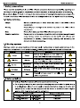
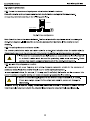
1.2 Warning symbols
Warnings caution you about conditions which can result in serious injury or death and/or damage to the
equipment, and advice on how to avoid the danger. Following warning symbols are used in this manual:
Symbols
A
A Warning
Danger
A
A
Do not
Hot sides
Note
Name
Instruction
Abbreviation
Serious physical injury or even death may
Danger
occur if not follow the relative requirements
Physical injury or damage to the devices may
Warning
occur if not follow the relative requirements
A
A
Damage to the PCBA board may occur if not
Electrostatic
follow the relative requirements
discharge
_
Sides of the device may become hot. Do not
Hot sides
touch.
Physical hurt may occur if not follow the
Note
relative requirements
A
Note
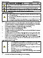
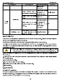
1.3 Safety guidelines
今
A
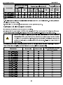
Do not carry out any wiring and inspection or changing components when the power supply
is applied. Ensure all input power supply is disconnected before wiring and checking and
always wait for at least the time designated on the inverter or until the DC bus voltage is
less than 36V. Below is the table of the waiting time:
_
Minimum waiting time
Inverter module
Single-phase 220V
0.2kW-2.2kW
5 minutes
Three-phase 220V
0.2kW-2.2kW
5 minutes
2
Safety precautions
GoodrivelO inverters
Three-phase 380V
A
A
A
今
0.75kW-2.2kW
5 minutes
Do not refit the inverter unauthorizedly; otherwise fire, electric shock or other injury may
occur.
The base of the radiator may become hot during running. Do not touch to avoid hurt.
_
electrical parts and components inside the inverter are electrostatic. Take
measurements to avoid electrostatic discharge during relevant operation.
1.3.1 Delivery and installation
A
<>ÿ
今
Please install the inverter on fire-retardant material and keep the inverter away from
combustible materials.
Connect the braking optional parts (braking resistors or feedback units) according to the
wiring diagram.
Don't operate on the inverter if there is any damage or components loss to the inverter.
Don’t touch the inverter with wet items or body, otherwise electric shock may occur
Note:
Select appropriate moving and installing tools to ensure a safe and normal running of the inverter
and avoid physical injury or death. For physical safety, the erector should take some mechanical
protective measurements, such as wearing exposure shoes and working uniforms.
Ensure to avoid physical shock or vibration during delivery and installation.
Do not carry the inverter by its cover. The cover may fall off.
Install away from children and other public places.
The inverter cannot meet the requirements of low voltage protection in IEC61800-5-1 if the sea level
of installation site is above 2000m.
The pick-up current of the inverter may be above 3.5mA during operation. Ground with proper
techniques and ensure the grounding resistor is less than 10Q. The conductivity of PE grounding
conductor is the same as that of the phase conductor (with the same cross sectional area).
R, S and T are the input terminals of the power supply, while U, V and W are the motor terminals.
Please connect the input power cables and motor cables with proper techniques; otherwise the
damage to the inverter may occur.
1.3.2 Commissioning and running
Disconnect all power supplies applied to the inverter before the terminal wiring and
wait for at least the designated time after disconnecting the power supply
A
High voltage is present inside the inverter during running. Do not carry out any
operation except for the keypad setting.
.
The inverter may start up by itself when P01.21=1 Do not get close to the inverter
and motor.
The inverter can not be used as "Emergency-stop device".
The inverter can not be used to break the motor suddenly. A mechanical braking
device should be provided.
Note:
Do not switch on/off the input power supply of the inverter frequently.
3
Safety precautions
Goodrive10 inverters
For inverters that have been stored for a long time, check and fix the capacitance and try to run it
again before utilization (see Maintenance and Hardware Fault Diagnose).
Cover the front board before running, otherwise electric shock may occur.
1.3.3 Maintenance and replacement of components
Only qualified electricians are allowed to perform the maintenance, inspection, and
A
components replacement of the inverter.
Disconnect all power supplies to the inverter before the terminal wiring. Wait for at
least the time designated on the inverter after disconnection.
Take measures to avoid screws, cables and other conductive matters to fall into the
inverter during maintenance and component replacement.
Note:
Please select proper torque to tighten screws.
Keep the inverter, parts and components away from combustible materials during maintenance and
component replacement.
Do not carry out any isolation and pressure test on the inverter and do not measure the control
circuit of the inverter by megameter.
1.3 4 What to do after scrapping
A
There are heavy metals in the inverter. Deal with it as industrial effluent.
4
Product overview
GoodrivelO inverters
2 Product overview
2.1 Quick start-up
2.1.1 Unpacking inspection
Check as followings after receiving products:
1. Check that there are no damage and humidification to the package. If not, please contact with local
agents or INVT offices.
2. Check the information on the type designation label on the outside of the package to verify that the drive
is of the correct type. If not, please contact with local dealers or INVT offices.
3. Check that there are no signs of water in the package and no signs of damage or breach to the inverter.
If not, please contact with local dealers or INVT offices.
4. Check the information on the type designation label on the outside of the package to verify that the name
plate is of the correct type. If not, please contact with local dealers or INVT offices.
_
5. Check to ensure the accessories (including user's manual and control keypad) inside the device is
complete. If not, please contact with local dealers or INVT offices.
2.1.2 Application confirmation
Check the machine before beginning to use the inverter:
1. Check the load type to verify that there is no overload of the inverter during work and check that whether
the drive needs to modify the power degree.
_
2. Check that the actual current of the motor is less than the rated current of the inverter.
3. Check that the control accuracy of the load is the same of the inverter.
4. Check that the incoming supply voltage is correspondent to the rated voltage of the inverter.
2.1.3 Environment
Check as followings before the actual installation and usage:
1, Check that the ambient temperature of the inverter is below 40°C. If exceeds, derate 3% for every
additional 1 °C. Additionally, the inverter can not be used if the ambient temperature is above 50°C.
_
Note: for the cabinet inverter, the ambient temperature means the air temperature inside the cabinet.
2. Check that the ambient temperature of the inverter in actual usage is above -10°C. If not, add heating
facilities.
Note: for the cabinet inverter, the ambient temperature means the air temperature inside the cabinet.
3. Check that the altitude of the actual usage site is below 1000m. If exceeds, derate1% for every
additional 100m.
4. Check that the humidity of the actual usage site is below 90% and condensation is not allowed. If not,
_
inverter. If
add additional protective measures. _
add additional
6. Check that there is no conductive dust or flammable gas in the actual usage site. If
protection inverters. _
add additional protection inverters.
5. Check that the actual usage site is away from direct sunlight and foreign objects can not enter the
not,
not,
to
5
Product overview
GoodrivelO inverters
2.1.4 Installation confirmation
Check as followings after the installation:
1. Check that the load range of the input and output cables meet the need of actual load.
2. Check that the accessories of the inverter are correctly and properly installed. The installation cables
should meet the needs of every component (including reactors, input filters, output reactors, output filters,
DC reactors and braking resistors).
3. Check that the inverter is installed on non-flammable materials and the calorific accessories (reactors
and brake resistors) are away from flammable materials.
4. Check that all control cables and power cables are run separately and the routation complies with EMC
requirement,
5. Check that all grounding systems are properly grounded according to the requirements of the inverter.
_
_
_
6. Check that the free space during installation is sufficient according to the instructions in user’s manual.
7. Check that the installation conforms to the instructions in user's manual. The drive must be installed in
an upright position,
8. Check that the external connection terminals are tightly fastened and the torque is appropriate.
9. Check that there are no screws, cables and other conductive items left in the inverter. If not, get them
out.
2.1.5 Basic commissioning
Complete the basic commissioning as followings before actual utilization:
1. Autotune. If possible, de-coupled from the motor load to start dynamic autotune. Or if not, static autotune
is available.
2. Adjust the ACC/DEC time according to the actual running of the load.
3. Commission the device via jogging and check that the rotation direction is as required. If not, change the
rotation direction by changing the wiring of motor.
4. Set all control parameters and then operate.
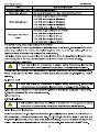
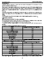
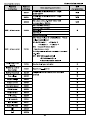
2.2 Product specification
Function
Specification
Single-phase 220(-15%)~240(+10%)
Input voltage (V)
Power input
Input current (A)
Input frequency (Hz)
Three-phase 220(-15%)~240(+10%)
Three-phase 380(-15%)~440(+10%)
Refer to 2.5
50Hz or 60Hz
Allowed range: 47
GoodrivelO inverters
Product overview
Function
Specification
frequency
Adjustable-speed ratio
1:100
150% of rated current: 1 minute
Overload capability
180% of rated current: 10 seconds
200% of rated current: 1 second
Key functions
Temperature
measurement accuracy
Terminal switch input
resolution
Terminal analog input
resolution
Analog input
Running
Analog output
control
Digital input
Digital output
Communication
Stop mode and anti-overtemperature of the bus
Overtemperature point ±3°C
<2ms
<20mV
1 input 0~10V/0~20mA
1 input 0~10V/0~20mA
5 common input
_
1 Y output (commonly used with digital output) and 1
rogrammable relay output
485 communication
Digital setting, analog setting, multi-step speed setting,
Frequency setting
PID setting, MODBUS communication setting and so on
Switch between different settings
Automatic voltage
adjustment
Fault protection
Mountable method
Temperature of the
running 6nvironm6nt
Others
Cooling
Keep output voltage stable when the grid voltage changes
More than 10 fault protections
Wall mountable
-10~50°C, derate above 40°C
Single/three-phase 220V 0.2-0.75kW natural cooling
Single/three-phase 220V 1.5-2.2kW, three-phase 380V
0.75-2.2kW
Braking unit
Embedded
DC reactor
Not optional
Braking resistor
EMC filter
Optional and external
Optional C2 filter
Product overview
GoodrivelO inverters
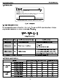
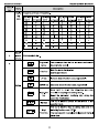
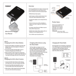
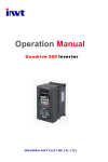
2.3 Name plate
C€
IPOO
MODEL: GD10 -2R2G- 4- B
POWER: 2.2kW
INPUT: AC 3PH 380V(-15% )-440V(+10%) 7.1A 47Hz- 63Hz
OUTPUT: AC 3PH 0V -Vin 5.5A 0Hz- 400Hz
S/N:
MADE IN CHINA
SHENZHEN INVT ELECTRIC CO., LTD.
Fig 2-1 Name plate
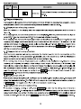
2.4 Type designation key
The type designation contains information on the inverter. The user can find the type designation on the type
designation label attached to the inverter or the simple name plate.
GDIO
?
4
旦
- 2R2G
- ??
?
Fig 2-2 Product type
Detailed description of the sign
Field identification
Sign
Abbreviation
?
Product abbreviation
Rated power
?
Power range + Load type
Detailed content
GoodrivelO is shorted for GD10.
2R2-2.2kW
—
G Constant torque load
4: Three-phase 380(-15%)~440(+10%)
Voltage degree
?
2: Three-phase 220(-15%)~240(+10%)
Voltage degree
S2: Single-phase 220(-15%)~240(+10%)
Lot No.
?
B: Standard braking unit
Lot No.
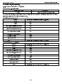
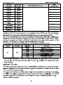
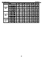
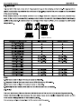
2.5 Rated specifications
Output power(kW)
Input current(A)
GD10-0R2G-S2-B
0.2
4.9
1.6
GD10-0R4G-S2-B
0.4
6.5
2.5
GD10-0R7G-S2-B
0.75
9.3
4.2
GD10-1R5G-S2-B
1.5
15.7
7.5
Model
Single-phase
220V
Output current (A)
GD10-2R2G-S2-B
2.2
24
10
Three-phase
GD10-0R2G-2-B
0.2
1.9
1.6
220V
GD10-0R4G-2-B
0.4
2.7
2.5
GD10-0R7G-2-B
0.75
4.9
4.2
8
Goodrive10 inverters
Product overview
Model
Three-phase
380V
Output power(kW)
Input current(A)
Output current (A)
GD10-1R5G-2-B
1.5
9.0
7.5
GD10-2R2G-2-B
2.2
15
10
GD10-0R7G-4-B
0.75
3.2
2.5
GD10-1R5G-4-B
1.5
4.3
GD10-2R2G-4-B
2.2
4.2
5.5
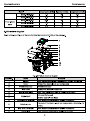
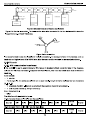
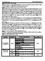
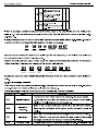
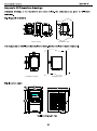
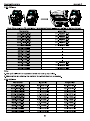
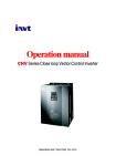
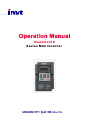
2.6 Structure diagram
Below is the layout figure of the inverter (take the inverter of 2.2kW as the example).
2
3
4
5
6
8
9
10
11
Fig 2-3 Product structure diagram
Serial No.
Name
Keypad
2
Cover
3
POWER indicator
4
Side cover
5
Simple name plate
6
Keypad port
8
Control circuit terminals
9
巳obbin winder
10
Main circuit terminals
11
Name plate
Illustration
See Keypad Operation Procedure lor detailed information
Protect the internal parts and components
POWER indicator
Protect the internal components
See Type Designation Key for detailed information
Connect the keypad
6 is for external installation
See Electric Installation for detailed information
To protect the internal parts and components, detachable for
wiring
See Electric Installation for detailed information
See Product Overview
9
detailed information
Installation guidelines
GoodrivelO inverters
3 Installation guidelines
The chapter describes the mechanical installation and electric installation.
<>ÿ
<>ÿ
A
<>ÿ
Only qualified electricians are allowed to carry out what described in this chapter.
Please operate as the instructions in Safety Precautions. Ignoring these may cause
physical injury or death or damage to the devices.
Ensure the power supply of the inverter is disconnected during the operation. Wait for at
least the time designated until the POWER indicator is off after the disconnection if the
power supply is applied.
The installation and design of the inverter should be complied with the requirement of
the local laws and regulations in the installation site. If the installation infringes the
requirement, our company will exempt from any responsibility. Additionally, if users do
not comply with the suggestion, some damage beyond the assured maintenance range
may occur.
3.1 Mechanical installation
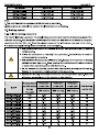
3.1.1 Installation environment
The installation environment is the safeguard for a full performance and long-term stable functions of the
inverter. Check the installation environment as followings:
Environment
Installation site
Conditions
Indoor
~+40°C , and the temperature changing rate is less than O.S'C /minute.
If the ambient temperature of the inverter is above 40 °C , derate 3% for every
additional TC.
-1ÿ°C
It is not recommended to use the inverter if the ambient temperature is above
60°C.
Environment
temperature
In order to improve the reliability of the device, do not use the inverter if the
ambient temperature changes frequently.
Please provide cooling fan or air conditioner to control the internal ambient
temperature below the required one if the inverter is used in a close space
such as in the control cabinet.
When the temperature is too low, if the inverter needs to restart to run after a
long stop, it is necessary to provide an external heating device to increase
the internal temperature, otherwise damage to the devices may occur.
RH<90%
Humidity
Storage
temperature
Running environment
condition
No condensation is allowed.
The maximum relative humility should be equal to or less than 60% in
corrosive air.
_
-40°C ~ +70°C, and the temperature changing rate is less than 1°C/minute.
The installation site of the inverter should:
keep away from the electromagnetic radiation source;
10
Installation guidelines
Goodrive10 inverters
Environment
Conditions
keep away from contaminative air, such as corrosive gas, oil mist and
flammable gas;
ensure foreign objects, such as metal power, dust, oil, water can not enter
into the inverter(do not install the inverter on the flammable materials such as
wood);
keep away from direct sunlight, oil mist, steam and vibration environment.
Altitude
Vibration
Installation direction
Below 1000m
If the sea level is above 1000m, please derate 1% for every additional 100m.
< 5.8m/s2(0.6g)
The inverter should be installed on an upright position to ensure sufficient
cooling effect.
Note:
GoodrivelO series inverters should be installed in a clean and ventilated environment according
to enclosure classification.
Cooling air must be clean, free from corrosive materials and electrically conductive dust.
3.1.2 Installation direction
The inverter may be installed on the wall or in a cabinet.
The inverter must be installed in an upright position. Check the installation site according to the requirements
below. Refer to chapter Dimension Drawings in the appendix for frame details.
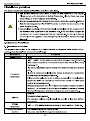
3.1.3 Installation manner
The inverter can be installed in wall mounting (for all frame sizes):
00001001
:1
11
a
f\
Wall mounting
Fig 3-1 Installation
(1) Mark the hole location. The location of the holes is shown in the dimension drawings in the appendix.
(2) Fix the screws or bolts to the marked locations..
(3) Position the drive onto the wall.
(4) Tighten the screws in the wall securely.
11
Installation guidelines
GoodrivelO inverters
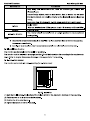
3.1.4 Installation space
11
B
I
Warm air
!::l:
A
A
Cool air
/I
B
Fig 3-2 Installation space
Note: The minimum space of A and B is 100mm.
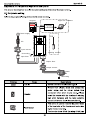
3.2 Standard wiring
3.2.1 Connection diagram of main circuit
Braking resistor
In pu t
re a ctor
Single - phase
power supply
Ou tpu t
re a ctor
L1
Ou tpu t
f il ter
In pu t
f il ter
Fuse
Braking resistor
u i-AIn pu t
re a ctor
Three - phase
power supply
Ou tpu t
re a ctor
F
Ou tpu t
f il ter
In pu t
f il ter
Fuse
Diagram 3-3 Connection diagram of main circuit
Note:
The fuse, DC reactor, braking resistor, input reactor, input filter, output reactor, output filter are
optional parts. Please refer to Peripheral Optional Parts for detailed information.
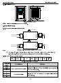
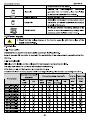
3.2.2 Terminals figure of main circuit
R/L1
S/L2
PB
十
U
V
w
©
Fig 3-4 Terminals of main circuit
Terminal
sign
Terminal name
Function
Power input of the main circuit
3-phase/single-phase AC input terminals which are generally
connected with the grid.
L1/R
L2/S
U
V
W
The inverter output
3-phase AC output terminals which are generally connected
with the motor.
12
Goodrive10 inverters
Terminal
sign
PB
(+)
©
Note:
Installation guidelines
Terminal name
Function
Braking resistor terminal
PB and (+) are connected to the external resistor.
Grounding terminal
Each machine has a standard PE terminal.
Do not use an asymmetrically constructed motor cable. If there is a symmetrically constructed
grounding conductor in the motor cable in addition to the conductive shield, connect the
grounding conductor to the grounding terminal at the inverter and motor ends.
Route the motor cable, input power cable and control cables separately.
'T'terminal can not be wired in single-phase input.
3.2.3 Wiring of terminals in main circuit
1. Fasten the grounding conductor of the input power cable with the grounding terminal of the inverter (PE)
by 360 degree grounding technique. Connect the phase conductors to R/L1, S/L2 and T terminals and
fasten,
2. Strip the motor cable and connect the shield to the grounding terminal of the inverter by 360 degree
grounding technique. Connect the phase conductors to U, V and W terminals and fasten.
3. Connect the optional brake resistor with a shielded cable to the designated position by the same
procedures in the previous step.
4. Secure the cables outside the inverter mechanically.
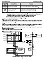
3.2.4 Connection diagram of the control circuit
Multi - function input terminal 1
S1
Multi - function input terminal 2
S2
Multi - function input terminal 3
J2
|ÿ
V
S3
}(:
Multi - function input terminal 4
S4
Multi - function input terminal 5
S5/Y
AO
>c: |ÿ
Open collector output
485+
485-
24V
10V
0-10V/0-20mA
J1
S5
GND
tÿh AO
GNDf
Frequency setting
power supply
lÿ
Al
ROA
ROC,)
V
TOND
PE
X
Figure 3-5 Connection diagram of the control circuit
13
R O 1
Installation guidelines
GoodrivelO inverters
3.2.5 Wiring diagram of control circuit
AO
S5/Y
o
o
1 RQA 1 ROC 1
AI
I
O
o
J1
V
I
I
J2
ra
485
V
J3
。]
o—
ON
1
J4
|24V| S1 I S2 |S3 |S4 I S5/Y I GND I GND |AI|Aÿ|10V|485+|485-|
Fig 3-6 Wiring of control circuit
Description
ROA
RO relay output
ROC
Contactor capability: 3A/AC250V.1A/DC30V
10V
Local power supply +10V
1, Input range: Al voltage and curren: 0-10V/0-20mAand switch by J3
2. Input impedance:voltage input: 20kQ; current input: 500Q
Al
3. Resolution: the minimum one is 5mV when 10V corresponds to 50Hz
4. Deviation ±1%, 25°C
Notel: Keyboard potentiometer set AM parameters of and Al terminal setAI2
parameters
24V
Local +24V power supply, 100mA
GND
+10V reference zero potential
1. Output range :0~10V or 0-20mA
AO
2. The voltage or the current output is depended on J2
3. Deviation±1%,25°C
S1
Switch input 1
S2
Switch input 2
S3
Switch input 3
S4
Switch input 4
S5
Switch input 5
丫
485+
485-
Digital output
1. Internal impedance:3.3kQ
2. 0-4V corresponds to low electric level input and
7-30V corresponds to high electric level input
3. Max input frequency:1kHz
4. All are programmable digital input terminal. User
can set the terminal function through function
codes.
Common terminal for S5/Y and switch by J1
Note : S5 and Y can not be used at the same time
terminal
485 communication interface and 485 differential signal interface
If it is the standard 485 communication interface, please use twisted pairs or
shield cable.
14
Installation guidelines
GoodrivelO inverters
3.3 Layout protection
3.3.1 Protect the inverter and input power cable in short-circuit situations
Protect the inverter and input power cable in short circuit situations and against thermal overload.
Arrange the protection according to the following guidelines.
Inverter
Input cable
M
Fuse
Fig 3-10 Fuse configuration
Note: Select the fuse as the manual indicated. The fuse will protect the input power cable from damage in
short-circuit situations. It will protect the surrounding devices when the internal of the inverter is short
circuited,
3.3.2 Protecting the motor and motor cables
The inverter protects the motor and motor cable in a short-circuit situation when the motor cable is
dimensioned according to the rated current of the inverter. No additional protection devices are needed.
A
令
If the inverter is connected to multiple motors, a separate thermal overload switch
or a circuit breaker must be used for protecting each cable and motor. These
devices may require a separate fuse to cut off the short-circuit current.
3.3.3 Implementing a bypass connection
It is necessary to set power frequency and variable frequency conversion circuits for the assurance of
continuous normal work of the inverter if faults occur in some significant situations.
In some special situations, for example, if it is only used in soft start, the inverter can be conversed into
power frequency running after starting and some corresponding bypass should be added.
A
Never connect the supply power to the inverter output terminals U, V and W.
Power line voltage applied to the output can result in permanent damage to
the inverter.
If frequent shifting is required, employ mechanically connected switches or contactors to ensure that the
motor terminals are not connected to the AC power line and inverter output terminals simultaneously.
15
Keypad operation procedure
GoodrivelO inverters
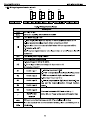
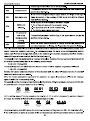
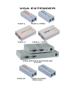
4 Keypad operation procedure
The keypad is used to control GoodrivelO series inverters, read the state data and adjust parameters.
1
S.S.S.S.S.
o 42
S®®
3
k 關|5瞭 ©I
Fig 4-1 Keypad
Note: Fix the external keypad with M3 screws or the installation bracket. The installation bracket is
optional.
Serial
No.
Description
Name
LED off means that the inverter is in the stopping
state; LED blinking means the inverter is in the
RUN/TUNE
parameter autotune state; LED on means the
inverter is in the running state.
FED/REV LED
LED off means the inverter is in the forward rotation
FWD/REV
state; LED on means the inverter is in the reverse
rotation state
State
LED for keypad operation, terminals operation and
LED
remote communication control
LED off means that the inverter is in the keypad
operation state; LED blinking means the inverter is in
the terminals operation state; LED on means the
inverter is in the remote communication control state.
LOCAL/REMOT
LED for faults
LED on when the inverter is in the fault state; LED off
TRIP
in normal state; LED blinking means the inverter is in
the overload pre-alarm state.
Mean the unit displayed currently
2
3
Unit
a
LED
Code
Hz
Frequency unit
A
Current unit
V
Voltage unit
RPM
Rotating speed unit
%
Percentage
5-figure LED display displays various monitoring data and alarm code such as set
16
Keypad operation procedure
GoodrivelO inverters
Serial
No.
Description
Name
display
ing
zone
frequency and output frequency.
Displayed Corres Displayed Corres Displayed Corres Displayed Corres
word 3ÿnd wore word >ond word word 3ÿnd wore word pond wore
0
5
E
2
B
6
4
5
8
8
3
9
R
厂
C
d
D
E
H
5
o
p
3
3
A
b
巳
E
F
r,
p
F
N
n
c<
S
b
U
Programmi
ng key
Enter or escape from the first level menu and remove
the parameter quickly
V
Digital
4
potenti
ometer
5
Corresponds to AM.
PRG
ESC
DATA
Button
»
ShF-
RST
Confirm parameters
UP key
Increase data or function code progressively
DOWN key
Decrease data or function code progressively
Right-shift
Move right to select the displaying parameter
circularly in stopping and running mode.
key
<!> RUN
STOP
Enter the menu step-by-step
Entry key
©
Select the parameter modifying digit during the
parameter modification
This key is used to operate on the inverter in key
operation mode
Run key
This key is used to stop in running state and it is
limited by function code P07.04
This key is used to reset all control modes in the fault
Stop/
Reset key
alarm state
17
GoodrivelO inverters
Serial
No.
Keypad operation procedure
Description
Name
QUICK
JOG
The function of this key is confirmed by function code
Quick key
P07.02.
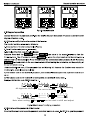
4.2 Keypad displaying
The keypad displaying state of GoodrivelO series inverters is divided into stopping state parameter, running
state parameter, function code parameter editing state and fault alarm state and so on.
4.1.1 Displayed state of stopping parameter
When the inverter is in the stopping state, the keypad will display stopping parameters which is shown in
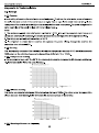
figure 4-2.
In the stopping state, various kinds of parameters can be displayed. Select the parameters to be displayed or
not by P07.07. See the instructions of P07.07 foÿ the detailed definition of each bit.
In the stopping state, there are 14 stopping parameters can be selected to be displayed or not. They are: set
frequency, bus voltage, input terminals state, output terminals state, PID reference, PID feedback, AM, AI2
and the current stage of multi-stage speeds, pulse counting value. P07.07 can select the parameter to be
displayed or not by bit and[» /SHIFT| can shift the parameters form left to right, |QUICK/J6G|(P07.02=2) can
shift the parameters form right to left.
4.1.2 Displayed state of running parameters
After the inverter receives valid running commands, the inverter will enter into the running state and the
keypad will display the running parameters. RUN/TUNE LED on the keypad is on, while the FWD/REV is
determined by the current running direction which is shown as figure 4-2.
In the running state, there are 22 parameters can be selected to be displayed or not. They are: running
frequency, set frequency, bus voltage, output voltage, output torque, PID reference, PID feedback, input
terminals state, output terminals state, and the current stage of multi-stage speeds, pulse counting value, AM,
AI2, percentage of motor overload, percentage of inverter overload, linear speed. P07.05 and P07.06 can
select the parameter to be displayed or not by bit and[)> /SHIFTl can shift the parameters form left to right,
|QUICK/J6G|(P07.02=2) can shift the parameters from right to left.
4.1.3 Displayed state of fault
If the inverter detects the fault signal, it will enter into the fault pre-alarm displaying state. The keypad will
display the fault code by flicking. The TRIP LED on the keypad is on, and the fault reset can be operated by
the|STOP/RST| on the keypad, control terminals or communication commands.
4.1.4 Displayed state of function codes editing
In the state of stopping, running or fault, press |PRG/ESC~| to enter into the editing state (if there is a
password, see P07.00 ).The editing state is displayed on two classes of menu, and the order is: function
code group/function code numberÿfunction code parameter, press |DATA/ENT| into the displayed state of
function parameter. On this state, press |DATA/ENT| to save the parameters or press! PRG/ESCj to escape.
18
Keypad operation procedure
GoodrivelO inverters
s
D
SSGD-!
圓R 國
I I Y I IÿT I
RuNi iw ©i
Stopping parameter
5 LfU U 'I
o
圍 ®圍
tF
o
圍 E圍
k RUN|
k RUN| I 靜 ©|
|W
©I
Running parameter
Fault parameter
Fig 4-2 Displayed state
4.2 Keypad operation
Operate the inverter via operation panel. See the detailed structure description of function codes in the brief
diagram of function codes.
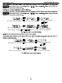
4.2.1 How to modify the function codes of the inverter
The inverter has three levels menu, which are:
1. Group number of function code (first-level menu)
2, Tab of function code (second-level menu)
3. Set value of function code (third-level menu)
Remarks: Press both the
_
|PRG/ESC] and the |DATA/ENT| can
return to the second-level menu from the
third-level menu. The difference is: pressing |DATA/ENf| will save the set parameters into the control panel,
and then return to the second-level menu with shifting to the next function code automatically; while pressing
|PRG/ESCl will directly return to the second-level menu without saving the parameters, and keep staying at
the current function code.
Under the third-level menu, if the parameter has no flickering bit, it means the function code cannot be
modified. The possible reasons could be:
1) This function code is not modifiable parameter, such as actual detected parameter, operation records and
so on;
2) This function code is not modifiable in running state, but modifiable in stop state.
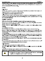
Example: Set function code P00.01 from 0 to 1.
•m
°
All digits are blinking
E
I
。?則
PMÿ
-o
圄 The unit is blinking
The unit is blinking
圊 回
f|°
3。
O
The unit is blinking
Note : when setting ,[S and
® +S]
囡
o
I_
o
o
o
,ÿ
3。
O
can be used to shift and adjust .
Fig 4-3 Sketch map of modifying parameters
4.2.2 How to set the password of the inverter
GoodrivelO series inverters provide password protection function to users. Set P7.00 to gain the password
19
Keypad operation procedure
Goodrive10 inverters
and the password protection becomes valid instantly after quitting from the function code editing state. Press
|PRG/ESC] again to the function code editing state, '*0.0.0.0.0" will be displayed. Unless using the
correct
password, the operators cannot enter it.
Set P7.00 to 0 to cancel password protection function.
The password protection becomes valid instantly after retreating form the function code editing state. Press
|PRG/ESC] again to the function code editing state,
will be displayed. Unless using the correct
password, the operators cannot enter it.
m
I—SGSSI:
圍
All digits are blinking
I PGSi~~
I PCl»
~~
M
-
--
The unit is blinking
The unit is blinking
圍
國
IPO
1C-t\ÿ
— —
m
IPSlgSI;
iaaqgai°
圊
The unit is blinking
The unit is blinking
+
Note : when setting ,is and
can be used to shift and adjust .
The unit is blinking
Fig 4-4 Sketch map of password setting
4.2.3 How to watch the inverter state through function codes
GoodrivelO series inverters provide group P17 as the state inspection group. Users can enter into P17
directly to watch the state.
i
•圍
a
I
PCCI-o
FT1-
通
All digits are blinking {W\ The unit is blinking
~~~~~ O
?
E no
The unit is blinking
•?
®
°
?
IP
則
ns siÿ
The unit is blinking
Fig 4-5 Sketch map of state watching
20
I!'
The unit is blinking
GoodrivelO inverters
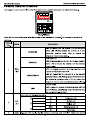
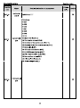
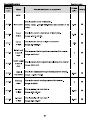
5 Function parameters
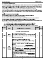
Function codes
The function parameters of GoodrivelO series inverters have been divided into 30 groups (POO
GoodrivelO inverters
Function
code
Function codes
Default
Detailed instruction of parameters
Name
value
Modify
rotation, reverse rotation and forward jogging and reverse
jogging of the multi-function terminals
running
command
2:Communication
(l,|[ÿCAL/REMOT|" on)ÿ
channel
The running command is controlled by the upper monitor via
communication
This parameter is used to set the maximum output
P00.03
P00.04
Max. output
frequency
Upper limit of
the running
frequency
frequency of the inverter. Users should pay attention to this
parameter because it is the foundation of the frequency
setting and the speed of acceleration and deceleration.
Setting range: P00.04~400.00Hz
50.00Hz
The upper limit of the running frequency is the upper limit of
the output frequency of the inverter which is lower than or
equal to the maximum frequency.
50.00Hz
Setting range:P00.05~P00.03 (Max. output frequency)
The lower limit of the running frequency is that of the output
frequency of the inverter.
Lower limit of
P00.05
the running
frequency
The inverter runs at the lower limit frequency if the set
frequency is lower than the lower limit one.
Note: Max. output frequency > Upper limit frequency >
0.00Hz
Lower limit frequency
Setting range:0.00Hz~P00.04 (Upper limit of the running
frequency)
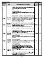
P00.06
A frequency
command
selection
P00.07
B frequency
command
selection
0:Keypad data setting
Modify the value of function code POO.10 (set the frequency
by keypad) to modify the frequency by the keypad.
1:Analog AM setting
2:Analog AI2 setting
Analog input terminal sets the frequency. There are 2
standard analog input terminal, of which AM is adjusted
through digital potentiometer, AI2 (0~10V/0~20mA)can be
switched by the jumper.
Note: when AI2 selects 0~20mA input, 20mA corresponds to
10V.
100.0% of the analog input corresponds to P00.03, -100.0%
of the analog input corresponds to the reverse P00.03.
6: Multi-stage speed running setting
22
0
O
2
O
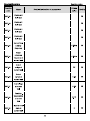
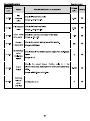
GoodrivelO inverters
Function
code
Name
Function codes
Detailed instruction of parameters
Default
value
Modify
The inverter runs at multi-stage speed mode when
P00.06=6 or P00.07=6. Set P05 to select the current
running stage, and set P10 to select the current running
frequency.
The multi-stage speed has the priority when P00.06 or
P00.07 does not equal to 6, but the setting stage can only
be the "M5 stage. The setting stage is 1-15 if P00.06 ?「
P00.07 equals to 6.
7: PID control setting
The running mode of the inverter is process PID control
when P00.06=7 or P00.07=7. It is necessary to set P09.
The running frequency of the inverter is the value after PID
effect. See P09 for the detailed information of the preset
source, preset value, feedback source of PID.
8:MODBUS communication setting
The frequency is set by MODBUS communication. See P14
for detailed information.
Note: A frequency and B frequency can not set as the same
frequency reference method.
P00.08
P00.09
B frequency
command
reference
Combination
type of the
setting
source
POO.10
Keypad set
frequency
0: Maximum output frequency, 100% of B frequency
setting corresponds to the maximum output frequency
1: A frequency command, 100% of B frequency setting
corresponds to the maximum output frequency. Select this
setting if it needs to adjust on the base of A frequency
command
0
O
0: A, the current frequency setting is Afreauency command
1: B, the current frequency setting is B frequency command
2: A+B, the current frequency setting is A frequency
command + B frequency command
3: A-B, the current frequency setting is A frequency
command - B frequency command
4: Max (A, B): The bigger one between A frequency
command and B frequency is the set frequency.
5: Min (A, B): The lower one between A frequency command
and B frequency is the set frequency.
Note:The combination manner can be shifted by
P05(terminal function)
0
O
When A and B frequency commands are selected as
"keypad setting", this parameter will be the initial value of
inverter
frÿquBncy
Setting range:0.00 Hz~P00.03(the Max. frequency)
50.00Hz
O
23
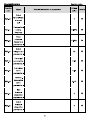
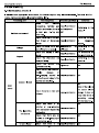
Goodrive10 inverters
Function
code
POO.11
Function codes
ACC time 1
Default
Detailed instruction of parameters
Name
value
ACC time means the time needed if the inverter speeds up
from 0Hz to the Max. One (P00.03).
Depend
on model
DEC time means the time needed if the inverter speeds
down from the Max, Output frequency to 0Hz (P00.03).
POO.12
DEC time 1
Goodrive10 series inverters define four groups of ACC/DEC Depend
time which can be selected by P05. The factory default on model
ACC/DEC time of the inverter is the first group.
Setting range of POO.11 and P00.12:0.0~3600.0s
0: Runs at the default direction, the inverter runs in the
forward direction. FWD/REV indicator is off.
Running
POO.13
direction
selection
1: Runs at the opposite direction, the inverter runs in the
reverse direction. FWD/REV indicator is on.
Modify the function code to shift the rotation direction of the
motor. This effect equals to the shifting the rotation direction
by adjusting either two of the motor lines (U, V and W). The
motor rotation direction can be changed by [QUICK/JOG] on
the keypad. Refer to parameter P07.02.
Note: When the function parameter comes back to the
default value, the motor's running direction will come back
to the factory default state, too. in some cases it should be
used with caution after commissioning if the change of
rotation direction is disabled.
2: Forbid to run in reverse direction: It can be used in some
special cases if the reverse running is disabled.
Carrier
frequency
1kHz
Carrier
POO.14
Electromagnetic
noise
Noise and leakage
current
Heating
eliminating
High
Low
Low
Low
High
High
10kHz
frequency
setting
15kHz
The relationship table of the motor type and carrier
frequency:
The factory value of
carrier frequency
Motor type
24
0
Depend
on model
Modify
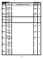
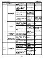
Goodrive10 inverters
Function
code
Function codes
Detailed instruction of parameters
Name
0.2~2.2kW
Default
value
Modify
4kHz
The advantage of high carrier frequency: ideal current
waveform, little current harmonic wave and motor noise.
The disadvantage of high carrier frequency: increasing the
switch loss, increasing inverter temperature and the impact
to the output capacity. The inverter needs to derate on high
carrier frequency. At the same time, the leakage and
electrical magnetic interference will increase.
Applying low carrier frequency is contrary to the above, too
low carrier frequency will cause unstable running, torque
decreasing and surge.
The manufacturer has set a reasonable carrier frequency
when the inverter is in factory. In general, users do not need
to change the parameter.
When the frequency used exceeds the default carrier
frequency, the inverter needs to derate 20% for each
additional 1k carrier frequency.
Setting range:1.0--15.0kHz
0:lnvalid
POO.16
AVR function
selection
1:Valid during the whole prodecure
The auto-adjusting function of the inverter can cancel the
impact on the output voltage of the inverter because of the
bus voltage fluctuation.
0:Nÿ
Function
POO.18
restore
parameter
O
operation
1:Restore the default value
2:Clear fault records
Note: The function code will restore to 0 after finishing the
operation of the selected function code.
0
Restoring to the default value will cancel the user password,
please use this function with caution.
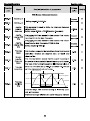
P01 Group Start-up and stop control
0:Start-up directly:start from the starting frequency P01.01
P01.00
Start mode
1:Start-up after DC braking: start the motor from the starting
frequency after DC braking (set the parameter P01.03 and
25
0
Goodrive10 inverters
Function
code
Name
Function codes
Detailed instruction of parameters
Default
value
P01.04). It is suitable in the cases where reverse rotation
may occur to the low inertia load during starting.
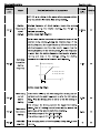
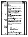
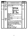
P01.01
Starting
Starting frequency of direct start-up means the original
frequency of
frequency during the inverter starting. See P01.02 for
direct
start-up
detailed information.
0.50Hz
Setting range: 0.00ÿ50.00Hz
Set a proper starting frequency to increase the torque of the
inverter during starting. During the retention time of the
starting frequency, the output frequency of the inverter is the
starting frequency. And then, the inverter will run from the
starting frequency to the set frequency. If the set frequency
is lower than the starling frequency, the inverter will stop
running and keep in the stand-by state. The starting
P01.02
Retention
time of the
starting
frequency
frequency is not limited in the lower limit frequency.
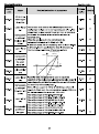
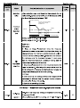
0.0s
Output frequency
fmax
f1 set by P01 . 01
t1 set by P01 . 02
f1
t1
Setting range: 0.0
T
Modify
Goodrive10 inverters
Function
code
Function codes
Detailed instruction of parameters
Name
Default
value
Modify
0:Linear type
The output frequency increases or decreases linearly.
0: Decelerate to stop: after the stop command becomes
valid, the inverter decelerates to decrease the output
P01.08
Stop
selection
frequency during the set time. When the frequency
decreases to 0, the inverter stops.
1: Coast to stop: after the stop command becomes valid, the
0
O
0.00Hz
O
0.00s
O
0.0%
O
inverter ceases the output immediately. And the load coasts
to stop at the mechanical inertia.
Starting
P01.09
frequency of
DC braking
Waiting time
P01.10
before DC
braking
P01.11
P01.12
P01.13
DC braking
current
Starting frequency of DC braking: start the DC braking when
running frequency reaches starting frequency determined
by P1.09.
Waiting time before DC braking: Inverters block the output
before starting the DC braking. After this waiting time, the
DC braking will be started so as to prevent over-current fault
caused by DC braking at high speed.
The value of P01.11 is the percentage
of rated current of inverter. The bigger the DC braking
DC
braking currentÿ
current is, the greater the braking torque is.
DC braking time: The retention time of DC brake. If the time
is 0, the DC brake is invalid. The inverter will stop at the set
deceleration time.
The setting range of P01.09: 0.00Hz~P00.03
The setting range of P01.10: 0.00~50.00s
The setting range of P01.11: 0.0~100.0%
The setting range of P01.12: 0.00~50.00s
DC braking
time
Dead time of
0.00s
During the procedure of switching FWD/REV rotation, set
27
0.0s
O
O
Goodrive10 inverters
Function
code
Name
FWD/REV
Function codes
Detailed instruction of parameters
the threshold by P01.14, which is as the table below:
rotation
Output frequency
FWD
Starting
frequency
Shift after the
starting frequency
Shift after the
zero frequency
REV
Setting range: 0.0
T
Default
value
Modify
Goodrive10 inverters
Function
code
Function codes
Detailed instruction of parameters
Name
one (valid if
the lower limit
frequency is
above 0)
Default
value
1: Stop
2: Hibernation
The inverter will coast to stop when the set frequency is
lower than the lower-limit one.if the set frequency is above
the lower limit one again and it lasts for the time set by
P01.20, the inverter will come back to the running state
automatically.
This function code determines the hibernation delay time.
Hibernation
P01.20
restore delay
time
When the running frequency of the inverter is lower than the
lower limit one, the inverter will pause to stand by.
When the set frequency is above the lower limit one again
and it lasts for the time set by P01.20, the inverter will run
automatically.
Note: The time is the total value when the set frequency is
0.0s
above the lower limit one.
Setting range: 0.0~3600.0s (valid when P01.19=2)
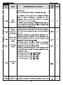
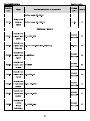
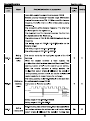
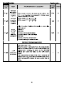
P01.21
Restart after
power off
This function can enable the inverter start or not after the
power off and then power on.
0: Disabled
0
1: Enabled, if the starting need is met, the inverter will run
automatically after waiting for the time defined by P01.22.
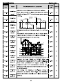
The function determines the waiting time before the
automatic running of the inverter when powering off and
then powering on.
The waiting
P01.22
time of restart
after power
t1 = P01.22
Output frequency
1.0s
off
t1
t
Running
Running Power off
Setting range: 0.0
Power on
Modify
Goodrive10 inverters
Function
code
Function codes
Detailed instruction of parameters
Name
Default
value
Setting range: 0.0~60.0s
Delay of the
P01.24
stopping
speed
Setting range: 0.0-100.0 s
0.0s
P02 Group Motor 1
Asynchronou
P02.01
s motor rated
0.1~3000.0kW
power
Asynchronou
s motor rated
frequency
0.01Hz
Depend
on model
Modify
Goodrive10 inverters
Function
code
Function codes
Detailed instruction of parameters
Name
Default
value
Asynchronou
P02.09
s motor
mutual
inductance
Depend
on model
0.1
T
Modify
Goodrive10 inverters
Function
code
Name
Function codes
Detailed instruction of parameters
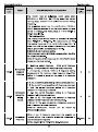
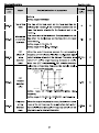
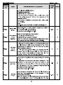
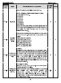
P04 Group
P04.00
Motor V/F
curve setting
P04.01
Torque boost
Default
value
SVPWM control
These function codes define the V/F curve of GoodrivelO
motor to meet the need of different loads.
0:Straight line V/F curveÿ applying to the constant torque
load
1:Multi-dots V/F curve
0
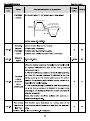
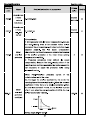
Torque boost to the output voltage for the features of low
0.0%
frequency torque. P04.01 is for the Max. Output voltage Vb.
P04.02 defines the percentage of closing frequency of
manual torque to fb.
Torque boost should be selected according to the load. The
bigger the load is, the bigger the torque is. Too big torque
boost is inappropriate because the motor will run with over
magnetic, and the current of the inverter will increase to add
the temperature of the inverter and decrease the efficiency.
When the torque boost is set to 0.0%, the inverter is
P04.02
Torque boost
close
automatic torque boost.
Torque boost threshold: below this frequency point, the
torque boost is valid, but over this frequency point, the
torque boost is invalid.
Output voltage
Vboost
Output frequency
Cut- off
fb
The setting range of P04.01:0.0%:(automatic)0.1%~10.0%
The setting range of P04.02:0.0%
Output voltage
V3
V2
V1
Output frequency
f1
f2 f3
20.0%
Modify
Goodrive10 inverters
Function
code
Function codes
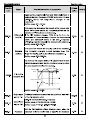
Name
Detailed instruction of parameters
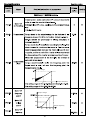
point 2
When P04.00 =1, the user can set V//F curve through
Default
value
P04.03~P04.08.
P04.06
Motor V/F
voltage point
2
Motor V/F
P04.07
frequency
point 3
V/F is generally set according to the load of the motor.
Note:V1 <V2< V3,f1 <f2<f3. Too high low frequency
voltage will heat the motor excessively or damage. The
00.0%
inverter may occur the overcurrent speed or overcurrent
protection.
The setting range of P04.03: 0.00Hz~P04.05
The setting range of P04.04, P04.06 and P04.08 :
0.0% 110.0%
The setting range of P04.05:P04.03~ P04.07
The setting range of P04.07:P04.05~P02.02(the rated
00.00Hz
?
P04.08
Motor V/F
voltage point
3
Motor V/F
P04.09
slip
compensatio
n gain
00.0%
frequency of motor 1 )
This function code is used to compensate the change of the
rotation speed caused by load during compensation
control to improve the rigidity of the motor. It can be set to
380V:
the rated slip frequency of the motor which is counted as
100%
below:
Af=fb-n*p/60
Of which, fb is the rated frequency of the motor, its function
code is P02.01; n is the rated rotating speed of the motor
and its function code is P02.02; p is the pole pair of the
motor. 100.0% corresponds to the rated slip frequency Af.
Note: no torque compensation for single-phase 220V
220V:
0%
inverters
Setting range:0.0~200.0%
Low
P04.10
frequency
vibration
control factor
High
P04.11
frequency
vibration
control factor
P04.12
Vibration
In the control mode, current fluctuation may occur to the
motor on some frequency, especially the motor with big
power. The motor can not run stably or overcurrent may
occur. These phenomena can be canceled by adjusting this
parameter.
The setting range of P04.10: 0~100
The setting range of P04.11: 0-100
The setting range of P04.12:0.00Hz~P00.03(the Max.
frequency)
control
33
10
10
30.00 Hz
Modify
Goodrive10 inverters
Function
code
Name
Function codes
Detailed instruction of parameters
Default
value
threshold
0: No operation
P04.26
Eneregy-savi
ng operation
1: Automatic eneergy-saving
The motor adjust the output voltage in non-load state
0
automatically.
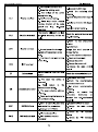
P05 Group Input terminals
S1 terminals
P05.01
function
selection
S2 terminals
P05.02
function
selection
S3 terminals
P05.03
function
selection
S4 terminals
P05.04
function
selection
S5 terminals
P05.05
function
selection
0: No function
1: Forward rotation operation
2: Reverse rotation operation
3: 3-wire control operation
4: Forward rotation jogging
5: Reverse rotation jogging
6: Coast to stop
7: Fault reset
8: Operation pause
9: External fault input
10:lncreasing frequency setting(UP)
11:Decreasing frequency setting(DOWN)
12:Cancel the frequency change setting
13:Shift between A setting and B setting
14:Shift between combination setting and A setting
15:Shift between combination setting and B setting
16:Multi-stage speed terminal 1
17:Multi-stage speed terminal 2
18:Multi-stage speed terminal 3
19:Multi- stage speed terminal 4
20:Multi- stage speed pause
21:ACC/DECtime option 1
25:PID control pause
26:Traverse Pause(stop at the current frequency)
27:Traverse reset(return to the center frequency)
28:Counter reset
30:ACC/DEC prohibition
31:Counter trigger
33:Cancel the frequency change setting temporarily
34
4
0
0
Modify
Goodrive10 inverters
Function
code
Function codes
Default
Detailed instruction of parameters
Name
value
34:DC brake
36:Shift the command to the keypad
37:Shift the command to the terminals
38:Shift the command to the communication
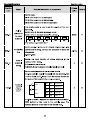
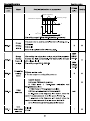
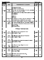
The function code is used to set the polarity of the input
Polarity
P05.10
selection of
the input
terminals
terminals,
Set the bit to 0, the input terminal is anode.
_
Set the bit to 1, the input terminal is cathode.
IBITTI
[BITOI
[BjT2|
[BjT3|
S3
S1
S2
The setting range:0x000~0x1F
S4
[BiT4|
S5
Setthe sample filter time of S1~S5 and HDI terminals. If the
interference is strong, increase the parameter to avoid the
disoperation.
0.000
K1
K1
K2
K2
FWD
OFF OFF
REV
Running
command
ON
OFF
OFF
ON
Stopping
Forward
running
Reverse
running
ON
ON
Hold on
COM
0x000
Modify
Goodrive10 inverters
Function
code
Name
Function codes
Detailed instruction of parameters
K1
K2
FWD
REV
COM
K1
K2
Runn ing
c omm and
OF F OF F
Sto ppin g
ON
OF F
Fo rwar d
ru nnin g
OF F
ON
Ho ld on
ON
ON
Reve rse
ru nnin g
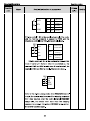
2:3-wire control 1; Sin is the enabling terminal in this mode,
and the running command is caused by FWD and the
direction is controlled by REV. Sin is natural closed. .
SB1
SB2
K
FW D
K
Running
command
ON
Forward
running
OFF
Reverse
running
Sln
REV
COM
3:3-wire control 2; Sin is the enabling terminal on this
mode, if set Si (i=1
SB1
FWD
Sln
SB3 REV
COM
SB2
Default
value
Modify
Goodrive10 inverters
Function
code
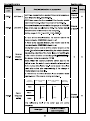
P05.14
S1 terminal
The function code defines the corresponding delay time of
switching on
electrical level of the programmable terminals from
switching on to switching off.
S1
terminal
switching off
delay time
S2 terminal
P05.16
Detailed instruction of parameters
Name
delay time
P05.15
Function codes
Default
value
0.000s
Si electric level
Si valid
Invalid
Switch on
delay
?ValidV//////////A invalid
t*Switch
off
delay
0.000s
Setting range:0,000~50.000s
0.000s
switching on
delay time
P05.17
S2
terminal
0.000s
switching off
delay time
S3 terminal
P05.18
0.000s
switching on
delay time
S3
P05.19
terminal
0.000s
switching off
delay time
S4 terminal
P05.20
switching on
0.000s
delay time
S4
P05.21
terminal
switching off
0.000s
delay time
S5 terminal
P05.22
switching on
0.000s
delay time
37
Modify
Goodrive10 inverters
Function
code
P05.23
Name
Function codes
Detailed instruction of parameters
S5 terminal
switching off
Default
value
Modify
0.000s
O
0.00V
O
0.0%
O
10.00V
O
100.0%
O
0.100s
O
0.00V
O
0.0%
O
10.00V
O
delay time
P05.32
P05.33
Lower limit of
AM
Correspondin
g setting of
the lower limit
of AM
P05.34
Upper limit of
AM
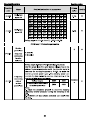
The function code defines the relationship between the
analog input voltage and its corresponding set value. If the
analog input voltage beyond the set minimum or maximum
input value, the inverter will count at the minimum or
maximum one.
When the analog input is the current input, the
corresponding voltage of 0~20mA is 0-10V.
In different cases, the corresponding rated value of 100.0%
is different. See the application for detailed information.
The figure below illustrates different applications:
Corresponding
setting
Correspondin
P05.35
P05.36
P05.37
P05.38
g setting of
the upper
limit of AH
AM input filter
P05.40
AI
-10V
10V
20mA
Al3
AI1/AI2
time
Lower limit of
AI2
Correspondin
g setting of
the lower limit
of AI2
P05.39
100%
Upper limit of
AI2
Correspondin
g setting of
the upper
-100%
Input filter time: this parÿ imeter is used to adjust the
sensitivity of the analog input. Increasing the value properly
can enhance the anti-interference of the analog, but weaken
the sensitivity of the analog input.
Note: AI2 can support 0 10V or 0 20mA input, when AI2
selects 0~20mA input, the corresponding voltage of 20mA is
5V. AI3 can support the output of -10V~+10V.
The setting range of P05.32:0.00V~P05.34
The setting range of P05.33:-100.0%~100.0%
The setting range of P05.34:P05.32~10.00V
The setting range of P05.35:-100.0%~100.0%
The setting range of P05.36:0.000s~10.000s
The setting range of P05.37:0.00V~P05.39
The setting range of P05.38:-100.0%~100.0%
The setting range of P05.39:P05.37~10.00V
?
?
38
100.0%
O
Goodrive10 inverters
Function
code
Name
Function codes
Detailed instruction of parameters
The setting range of P05.41:0.000s 10.000s
P05.41
?
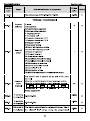
P06 Group
P06.01
Y1 output
selection
P06.03
Relay RO
output
P06.05
Polarity of
output
terminals
Default
value
0.100s
Output terminals
0:lnvalid
1:On operation
2:Forward rotation operation
3:Reverse rotation operation
4: Jogging operation
5:The inverter fault
6:Frequency degree test FDT 1
7:Frequency degree test FDT2
8:Frequency arrival
9:Zero speed running
10:Upper limit frequency arrival
11:Lower limit frequency arrival
12:Ready for operation
1(Overload pre-alarm
15: Underload pre-alarm
16:Completion of simple PLC stage
17:Completion of simple PLC cycle
18:Setting count value arrival
19:Defined count value arrival
20:ExternaI fault valid
22:Running time arrival
23:MODBUS communication virtual terminals output
The function code is used to set the pole of the output
terminal.
When the current bit is set to 0, input terminal is positive.
When the current bit is set to 1, input terminal is negative.
BIT3
BIT0
BIT2
BIT1
Reserved
Reserved
R01
Y
Setting range:00
0
00
Modify
Goodrive10 inverters
Function
code
Function codes
Detailed instruction of parameters
Name
Default
value
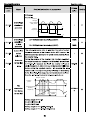
terminal switching on and off.
P06.11
RO switching
off delay time
Y electric level
Y valid
Invalid
H- Switch
on
delay
The setting range :0_000
invalid
ValidV//////////A
t*Switch off
delay
0.000s
Modify
GoodrivelO inverters
Function
code
Function codes
Detailed instruction of parameters
Name
Default
value
Modify
A °ÿSÿV (20mA)
P06.21
Corresponding
setting
AO output
filter time
0.0%
100.0%
0.000s
O
0
O
Setting range of P06.18 0.00V-10.00V
Setting range of P06.19 P06.17-100.0%
Setting range of P06.20 0.00V-10.00V
Setting range of P06.21 0.000s~10.000s
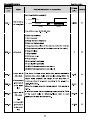
P07 Group Human-Machine Interface
0-65535
P07.00
User's
password
The password protection will be valid when setting any
non-zero number.
00000: Clear the previous user's password, and make the
password protection invalid.
After the user's password becomes valid, if the password is
incorrect, users cannot enter the parameter menu. Only
correct password can make the user check or modify the
parameters. Please remember all users' passwords.
Retreat editing state of the function codes and the password
protection will become valid in 1 minute. If the password is
available, press |PRG/ESC| to enter into the editing state of
the function codes, and then "O.O.O.O.O" will be displayed.
Unless input right password, the operator can not enter into
it.
Note: restoring to the default value can clear the password,
please use it with caution.
0: No function
P07.02
iQUICK/JOGl
function
1: Jogging running. Press
jogging running.
|QUICK/JOG| to realizes the
2: Shift the display state by the shifting key. Press
|QUICK/JOG| to shift the displayed function code from right
to left.
3: Shift between forward rotations and reverse rotations.
41
Goodrive10 inverters
Function
code
Name
Function codes
Detailed instruction of parameters
Default
value
Modify
Press |QUICK/J(5G| to shift the direction of the frequency
commands. This function is only valid in the keypad
commands channels.
4: Clear UP/DOWN settings. Press |QUICK/JOG|to clear the
set value of UP/DOWN.
5: Coast to stop. Press |QUICK/JOG| to coast to stop.
6: Shift the running commands source. Press |QUICK/JOG|
to shift the running commands source.
7:Quick commission mode(committee according to the
non-factory parameter)
Note: Press |QUICK/JC5G| to shift between forward rotation
and reverse rotation, the inverter does not record the state
after shifting during powering off. The inverter will run
according to parameter POO.13 during next powering on.
IQUICK/JOGI
the shifting
P07.03
sequence
selection of
running
command
P07.04
ISTOP/RSTl
stop function
When P07.02=6, set the shifting sequence of running
command channels.
0:Keypad control—terminals
control
-ÿcommunication
control
1:Keypad control——terminals control
2:Keypad control——
control
3:Terminals control--
0
O
0
O
0x03FF
O
control
Select the stop function by |STOP/RST|. |STOP/RST| is valid
in any state for the fault reset.
0:Only valid for the panel control
1:Both valid for panel and terminals control
2:Both valid for panel and communication control
3:Valid for all control modes
0x0000~0xFFFF
The
P07.05
parameter
selection1 of
running st3t6
BIT0:running frequency (Hz on)
BIT1:set frequency(Hz flickering)
BIT2:bus voltage (Hz on)
BIT3:output voltage(V on)
BIT4:output current(A on)
BIT5:running rotation speed (rpm on)
BIT6:output power(% on)
BIT7:output torque(% on)
42
Goodrive10 inverters
Function
code
Function codes
Detailed instruction of parameters
Name
Default
value
Modify
BIT8:PID reference(% flickering)
BIT9:PID feedback value(% on)
BIT10:input terminals state
BIT11:output terminals state
BIT12:torque set value(% on)
BIT13:pulse counter value
BIT14:length value
BIT15:current stage in multi-stage speed
0x0000~0xFFFF
The
P07.06
parameter
selection 2 of
running st3t6
BITO: analog AM value (V on)
BIT1: analog AI2 value (V on)
BIT4: motor overload percentage (% on)
BIT5: the inverter overload percentage (% on)
BIT6: ramp frequency reference value(Hz on)
0x0000
BIT7: linear speed
0x0000~0xFFFF
BITO:setfrequency(Hz on, frequency flickering slowly)
BIT1:bus voltage (V on)
BIT2:input terminals state
BIT3:output terminals state
parameter
BIT4:PID reference (% flickering)
selection of
BIT5:PID feedback value(% on)
the stop state
BIT7:analog AM value(V on)
BIT8:analog AI2 value(V on)
BIT11:current stage in multi-stage speed
BIT12:pulse counters
The
P07.07
Frequency
display
coefficient
0.01
OxOOFF
O
Goodrive10 inverters
Function
code
P07.12
Name
Module
temperature
Function codes
Detailed instruction of parameters
Default
value
Modify
Goodrive10 inverters
Function
code
P07.26
Function codes
Detailed instruction of parameters
Name
Factory bar
code 6
0x0000~0xFFFF
0:No fault
4:OC1
5:OC2
6:OC3
7:OV1
8ÿOV2
9ÿOV3
10ÿUV
P07.27
Current fault
type
11:Motor overload(OL1)
12:The inverter overload(OL2)
15:Overheat of the rectifier module(OH1)
16:Overheat fault of the inverter module(OH2)
17:Externalfault(EF)
18:485 communication fault(CE)
21:EEPROM operation fault(EEP)
22:PID response offline fault(PIDE)
24:Running time arrival(END)
25:Electrical overload(OL3)
36: Undervoltage fault(LL)
P07.28
Previous fault
type
45
Default
value
Modify
Goodrive10 inverters
Function
code
Name
P07.29
Previous 2
fault type
P07.30
Previous 3
fault type
P07.31
Previous 4
fault type
P07.32
Previous 5
fault type
Function codes
Detailed instruction of parameters
Current fault
P07.33
Default
value
0.00Hz
running
frequency
Ramp
P07.34
reference
0.00Hz
frequency at
current fault
Output
P07.35
voltage at
OV
current fault
P07.36
Output
current at
current fault
0.0A
Bus voltage
P07.37
P07.38
P07.39
0.0V
at current
fault
The Max.
temperature
at current
fault
O.CTC
Input terminal
state at
0
current fault
46
Modify
Goodrive10 inverters
Function
code
P07.40
P07.41
Name
Function codes
Detailed instruction of parameters
Output
terminal state
at current
fault
Default
value
0
Previous fault
running
0.00Hz
frequency
Ramp
P07.42
reference
0.00Hz
frequency at
previous fault
Output
P07.43
OV
voltage at the
previous fault
P07.44
P07.45
The output
current at the
previous fault
0.0A
Bus voltage
at the
0.0V
previous fault
P07.46
The Max.
temperature
at the
previous fault
P07.47
terminals
state at the
O.CTC
Input
0
previous fault
P07.48
Output
terminals
0
state at the
previous fault
47
Modify
Goodrive10 inverters
Function
code
P07.49
Name
Function codes
Detailed instruction of parameters
Previous 2
fault runnig
frequency
Default
value
0.00Hz
Output
P07.50
voltage at the
0.00Hz
previous 2
faults
P07.51
Output
current at the
previous 2
faults
0V
P07.52
Output
current at the
previous 2
fault
0.0A
P07.53
P07.54
Bus voltage
at the
0.0V
previous 2
fault
The Max.
temperature
at previous 2
fault
O.CTC
Input
terminals
P07.55
0
state at
previous 2
fault
Output
P07.56
terminals
state at
0
previous 2
fault
48
Modify
GoodrivelO inverters
Function
code
Function codes
Default
Detailed instruction of parameters
Name
value
P08 Group Enhanced function
P08.00
ACC time 2
P08.01
DEC time 2
P08.06
Jogging
running
frequency
P08.07
Jogging
running ACC
time
P08.08
Jogging
running DEC
time
P08.15
Traverse
range
This function applies to the industries where traverse and
convolution function are required such as textile and
P08.16
Sudden
jumping
frequency
range
chemical fiber.
The traverse function means that the output frequency of
P08.17
Traverse
boost time
Depend
on model
Setting range:0.0~3600.0s
This parameter is used to define the reference frequency
during jogging.
Setting range: 0.00Hz ~P00.03(the Max. frequency)
5.00Hz
The jogging ACC time means the time needed if the inverter Depend
runs from 0Hz to the Max. Frequency.
on model
The jogging DEC time means the time needed if the inverter
goes from the Max. Frequency (P0.03) to 0Hz.
Depend
Setting range:0.0~3600.0s
on model
the inverter is fluctuated with the set frequency as its center.
The route of the running frequency is illustrated as below, of
which the traverse is set by P08.15 and when P08.15 is set
as 0, the traverse is 0 with no function.
0.0%
0.0%
5.0s
Output freque ncy
Upper limit
Ji tter freq uency
Tra verse am plltu de
Center freque ncy
P08.18
Traverse
declining
time
Decel erate
5.0s
Lower limit
Accelerate
Fa ll time Raise tim e
o f traverse木 o f traverse
T
Traverse range: The traverse running is limited by upper
and low frequency.
The traverse range relative to the center frequency: traverse
49
Modify
Goodrive10 inverters
Function
code
Function codes
Default
Detailed instruction of parameters
Name
value
Modify
range AW=center frequencyxtraverse range P08.15.
Sudden jumping frequency = traverse range AWxsudden
jumping frequency range P08.16. When run at the traverse
frequency, the value which is relative to the sudden jumping
frequency.
The raising time of the traverse frequency: The time from
the lowest point to the highest one.
The declining time of the traverse frequency: The time from
the highest point to the lowest one.
The setting range of P08.15: 0.0~100.0%(relative to the set
frequency)
The setting range of P08.16: 0.0~50.0%(relative to the
traverse range)
The setting range of P08.17: 0.1~3600.0s
The setting range of P08.18: 0.1~3600.0s
P08.25
Setting
The counter works by the input pulse signals of the HDI
counting
terminals.
When the counter achieves a fixed number, the
value
0
O
0
O
0m
O
multi-function output terminals will output the signal of 'fixed
counting number arrival" and the counter go on working;
when the counter achieves a setting number, the
multi-function output terminals will output the signal of
''setting counting number arrival", the counter will clear all
numbers and stop to recount before the next pulse.
Reference
P08.26
counting
value
The setting counting value P08.26 should be no more than
the setting counting value P08.25.
The function is illustrated as below:
HDI
Setting
counting
arrival
RO1 , RO2
Fixed
counting
arrival
Setting range of P08.25:P08.26~65535
Setting range of P08.26:0~P08.25
P08.27
Setting
running time
Pre-set running time of the inverter. When the accumulative
running time achieves the set time, the multi-function digital
output terminals will output the signal of "running time
50
Goodrive10 inverters
Function
code
Function codes
Default
Detailed instruction of parameters
Name
value
Modify
arrival”.
Setting range:0~65535min
P08.28
P08.29
Time of fault
reset
Interval time
of automatic
fault reset
The time of the fault reset: set the fault reset time by
selecting this function. If the reset time exceeds this set
value, the inverter will stop for the fault and wait to be
repaired.
The interval time of the fault reset: The interval between the
time when the fault occurs and the time when the reset
action occurs.
Setting range of P08.28:0~10
0
O
1.0s
O
50.00Hz
O
5.0%
O
0.00Hz
O
Setting range of P08.29:0.1 3600.0s
?
P08.32
FDT
When the output frequency exceeds the corresponding
electrical
level
frequency of FDT electrical level, the multi-function digital
output terminals will output the signal of 'frequency level
detection
value
detect FDT" until the output frequency decreases to a value
lower than (FDT electrical level FDT retention detection
—
value) the corresponding frequency, the signal is invalid.
Below is the waveform diagram:
Output current
Overload
pre- warning
point
FDT
P08.33
T
retention
detection
value
Pre - warning
tim e
Pre -warning
tim e
RO1 , R O2
range
frequency)
Setting
of
P08.32:
0.00Hz~Pb0.03(the
T
Max.
Setting range of P08.33: 0.0~100.0%(FDT electrical level)
P08.36
Frequency
When the output frequency is among the below or above
arrival
range of the set frequency, the multi-function digital output
terminal will output the signal of "frequency arrival", see the
detection
value
diagram below for detailed information:
51
Goodrive10 inverters
Function
code
Name
Function codes
Default
Detailed instruction of parameters
value
O utput frequency
D etecting range
R eference frequency
T
Y,
RO1 , RO2
run
T
The setting range:0.00Hz~P00.03(the Max. frequency)
Energy
P08.37
Braking
enable
P08.38
Energy
Braking
threshold
voltage
P08.39
Cooling fan
running
mode
This parameter is used to control the internal braking pipe.
0:Disabled
1:Enabled
Note: Only applied to internal braking pipe.
After setting the original bus voltage, adjust this parameter
to brake the load appropriately. The factory value changes
with voltage level,
The setting range:200.0~2000.0V
0:Rated running mode
1:The fan keeps on running after power on
0x0000
0
220V
voltage:
380.0V
380V
voltage:
700.0V
0
Modify
Goodrive10 inverters
Function
code
Function codes
Detailed instruction of parameters
Name
0x000
Default
value
Modify
Goodrive10 inverters
Function
code
Function codes
Detailed instruction of parameters
Name
integral ratio
0x000
Default
value
Modify
Goodrive10 inverters
Function
code
Name
Function codes
Detailed instruction of parameters
Default
value
2:Analog channel AI2 reference
5:Multi-stage speed set
6:MODBUS communication set
The setting target of procedure PID is a relative one, 100%
of the setting equals to 100% of the response of the
controlled system.
The system is calculated according to the relative value
(0-100.0%).
Note:
Multi-stage speed reference, it is realized by setting P10
P09.01
Keypad PID
preset
When P09.00=0, set the parameter whose basic value is
the feedback value of the system.
The setting range:-100.0%~100.0%
0.0%
Select the PID channel by the parameter.
P09.02
PID feedback 1:Analog channel AI2 feedback
source
4:MODBUS communication feedback
Selection
Note: The reference channel and the feedback channel can
not coincide, otherwise, PID can not control validly.
PID output
feature
selection
0: PID output is positive: When the feedback signal exceeds
the PID reference value, the output frequency of the inverter
will decrease to balance the PID. For example, the strain
PID control during wrapup
1: PID output is negative: When the feedback signal is
stronger than the PID reference value, the output frequency
of the inverter will increase to balance the PID. For
example, the strain PID control during wrapdown
0
P09.04
Proportional
gain (Kp)
The function is applied to the proportional gain P of PID
input.
P determines the strength of the whole PID adjuster. The
parameter of 100 means that when the offset of PID
feedback and reference value is 100%, the adjusting range
of PID adjustor is the Max. Frequency (ignoring integral
function and differential function).
The setting range:0.00~100.00
1.00
P09.05
Interval
time(Ti)
This parameter determines the speed of PID adjustor to
carry out integral adjustment on the deviation of PID
feedback and reference.
When the deviation of PID feedback and reference is 100%,
the integral adjustor works continuously after the time
0.10s
P09.03
55
Modify
Goodrive10 inverters
Function
code
Name
Function codes
Detailed instruction of parameters
Default
value
(ignoring the proportional effect and differential effect) to
achieve the Max. Frequency (P00.03) or the Max. Voltage
(P04.31). Shorter the integral time, stronger is the
adjustment
Setting range: 0.01-10.00s
P09.06
P09.07
Differential
time(Td)
This parameter determines the strength of the change ratio
when PID adjustor carries out integral adjustment on the
deviation of PID feedback and reference.
If the PID feedback changes 100% during the time, the
adjustment of integral adjustor (ignoring the proportional
effect and differential effect) is the Max. Frequency
(P00.03). Longer the integral time, stronger is the adjusting.
Setting range: 0.00-10.00s
Sampling
This parameter means the sampling cycle of the feedback.
The modulator calculates in each sampling cycle. The
longer the sapling cycle is, the slower the response is.
cycle(T)
0.00s
0.10s
Setting range: 0.00-100.00s
As shown in the diagram below, PID adjustor stops to work
during the deviation limit. Set the function properly to adjust
the accuracy and stability of the system.
Feedback value
Reference
value
P09.08
PID control
deviation limit
Bias limit
0.0%
T
Output frequency
T
Setting range:0.0~100.0%
P09.09
P09.10
Output upper
limit of PID
Output lower
limit of PID
These parameters are used to set the upper and lower limit
of the PID adjustor output.
100.0 % corresponds to Max. Frequency
Setting range of P09.09: P09.10-100.0%
Setting range of P09.10: -100.0%~P09.09
Set the PID feedback offline detection value, when the
P09.11
Feedback
oTTime
detection value is smaller than or equal to the feedback
56
100.0%
0.0%
0.0%
Modify
Goodrive10 inverters
Function
code
Function codes
Default
Detailed instruction of parameters
Name
value
detection
offline detection value, and the lasting time exceeds the set
value
value in P09.12, the inverter will report "PID feedback offline
fault" and the keypad will display PIDE.
Output frequency
T1 < T2 , so the inverter
continues to work
t2 = P09 . 12
Feedback
P09.12
offline
detection
time
P09.11
_
t1
I
I
_J
V-
t2
PIDE
n
W///////////,In runningv///\ Fault output PIDE
Setting range of P09.11: 0.0-100.0%
Setting range of P09.12: 0.0~3600.0s
0x00
T
1.0s
Modify
Goodrive10 inverters
Function
code
P10.04
Function codes
Default
Name
Detailed instruction of parameters
Multi-stage
define the running frequency and direction of all stages.
Note: The symbol of multi-stage determines the running
speed 1
direction of simple PLC. The negative value means reverse
value
0.0%
rotation,
P10.06
P10.08
P10.10
Multi-stage
P10.30
0.0%
P10.32
ACC time
(2 stags)
Multi-stage
P10.06
0.0%
speed 3
speed 4
P10.28
P10.02
speed 2
Multi-stage
DEC time
(2 stages)
P10.04
P10.03
P10.05
P10.07
P10.31
P10.33
Multi-stage speeds are in the range of ~fma:<~W and it can
be
Goodrive100 series inverters can set 16 stages speed,
selected by the combination of multi-stage terminals 1
Outp ut freq uency
T
T
T
T
T
0.0%
Modify
GoodrivelO inverters
Function
code
P10.30
Function codes
Detailed instruction of parameters
Name
Multi-stage
S1
OFF ON
OFF ON OFF ON OFF ON
speed 14
S2
OFF OFF
ON
S3
OFF OFF OFF OFF ON ON ON ON
S4
OFF OFF OFF OFF OFF OFF OFF OFF
stage
P10.32
Multi-stage
speed 15
0
2
ON OFF OFF ON ON
3
4
5
Default
value
0.0%
6
S1
OFF ON
OFF ON OFF ON OFF ON
S2
OFF OFF
ON
S3
OFF OFF OFF OFF ON ON ON ON
ON OFF OFF ON ON
0.0%
S4 ON ON ON ON ON ON ON ON
9
stage 8
10
11 12 13 14 15
Setting range of P10.(2n,1<n<17): -100.0-100.0%
P11 Group
Protective parameters
Sudden
power loss
P11.01
P11.02
frequency
decreasing
function
selection
Frequency
decreasing
ratio of
sudden
power loss
0
0: Enabled
1: Disabled
Setting range: 0.00Hz/s~P00.03 (the Max. frequency)
After the power loss of the grid, the bus voltage drops to the
sudden frequency-decreasing point, the inverter begin to
decrease the running frequency at P11.02, to make the
inverter generate power again. The returning power can
maintain the bus voltage to ensure a rated running of the
inverter until the recovery of power.
220V
380V
Voltage degree
Frequency-decreasing point
260V
460V
of sudden power loss
Note:
1. Adjust the parameter properly to avoid the stopping
caused by inverter protection during the switching of the
grid.
2. Prohibition of input phase protection can enable this
function.
_
59
10.00Hz/
s
Modify
Goodrive10 inverters
Function
code
Function codes
Default
Detailed instruction of parameters
Name
value
0:Disabled
1:Enabled
Overvoltage
P11.03
speed loss
Output
voltage
Over- voltage
stall point
protection
T
Output
frequency
T
P11.04
Overvoltage
speed loss
voltage
protection
Current limit
P11.05
action
selection
Automatic
P11.06
current limit
level
120~150%(standard bus voltage )(380V)
140%
120-150%(standard bus voltage )(220V)
120%
The actual increasing ratio is less than the ratio of output
frequency because of the big load during ACC running. It is
necessary to take measures to avoid overcurrent fault and
the inverter trips.
During the running of the inverter, this function will detect
the output current and compare it with the limit level defined
in P11.06. If it exceeds the level, the inverter will run at
stable frequency in ACC running, or the inverter will derate
to run during the constant running. If it exceeds the level
continuously, the output frequency will keep on decreasing
to the lower limit. If the output current is detected to be lower
than the limit level, the inverter will accelerate to run.
160.0%
Output current
Limiting
point
The
P11.07
decreasing
ratio during
current limit
T
Output frequency
Setting
frequency
10.00Hz/
s
ACC
Setting range of P11.05:
0:current limit invalid
1:current limit valid
Setting range of P11.06:50.0
Constant
speed
T
Modify
Goodrive10 inverters
Function
code
P11.08
Function codes
Name
Detailed instruction of parameters
Overload
pre-alarm of
the motor or
The output current of the inverter or the motor is above
P11.09 and the lasting time is beyond P11.10ÿ overload
pre-alarm will be output.
Default
value
0x000
the inverter
Overload
P11.09
Output frequency
FD T level
Lag
pre-alarm
test level
150%
T
R O1 , RO2
T
P11.10
Overload
pre-alarm
detection
time
Setting range of P11.08:
Enable and define the overload pre-alarm of the inverter or
the motor.
Setting range: 0x000~0x131
LED ones:
0:Overload pre-alarm of the motor, comply with the rated
current of the motor
1:Overload pre-alarm of the inverter, comply with the rated
current of the inverter
LED tens:
0:The inverter continues to work after underload pre-alarm
1:The inverter continues to work after underload pre-alarm
and the inverter stops to run after overload fault
2: The inverter continues to work after overload pre-alarm
and the inverter stops to run after underload fault
3. The inverter stops when overloading or underloading.
LED hundreds :
0:Detection all the time
1:Detection in constant running
Setting range of P11.09: P11.11-200%
Setting range of P11.10: 0.1~60.0s
61
1.0s
Modify
Goodrive10 inverters
Function
code
Name
Function codes
Detailed instruction of parameters
Default
value
Modify
Detection
P11.11
level of the
underload
pre-alarm
If the inverter current or the output current is lower than
P11.11, and its lasting time is beyond P11.12, the inverter
will output underload pre-alarm.
Setting range of P11.11: 0
50%
O
Goodrive10 inverters
Function
code
Function codes
Detailed instruction of parameters
Name
Default
value
Note: The address of the slave cannot set to 0.
Set the digital transmission speed between the upper
monitor and the inverter.
0:1200BPS
1:2400BPS
2ÿ4800BPS
P14.01
Baud rate
3:9600BPS
4ÿ19200BPS
5:38400BPS
Note: The baud rate between the upper monitor and the
inverter must be the same. Otherwise, the communication is
not applied. The bigger the baud rate, the quicker the
communication speed.
P14.02
Digital bit
checkout
setting
The data format between the upper monitor and the inverter
must be the same. Otherwise, the communication is not
applied.
0: No check (N,8,1
1:ÿdd check (Eÿ8,1)forRTU
2:Even check (0,8,1)for RTU
3:Nocheck(N,8,2)for RTU
4: Odd check(E,8,2)for RTU
5:Even check(0,8,2)for RTU
0
4
Modify
Goodrive10 inverters
Function
code
Function codes
Detailed instruction of parameters
Name
Default
value
0:Alarm and stop freely
Transmission
P14.05
fault
processing
1:No alarm and continue to run
2:No alarm and stop according to the stop means(only
under the communication control)
3:No alarm and stop according to the stop means(under all
control modes)
0x00
0
Modify
Goodrive10 inverters
Function
code
Function codes
Detailed instruction of parameters
Name
Default
value
motor
Display current power of the motor.
P17.08
Motor power
Setting range: -300.0%~300.0%(the rated current of the
0.0%
motor)
P17.09
P17.11
Output
Display the current output torque of the inverter.
torque
Range: -250.0-250.0%
DC bus
Display current DC bus voltage of the inverter
voltage
Range: 0.0-2000.0V
Switch input
P17.12
terminals
state
Switch output
P17.13
P17.14
P17.18
P17.19
P17.20
terminals
state
Digital
adjustment
Counting
value
AM input
Display current Switch input terminals state of the inverter
Range: 0000-00FF
Display current Switch output terminals state of the inverter
Range: 0000-000F
Display the adjustment through the keypad of the inverter.
Range : 0.00Hz~P00.03
Display the current counting number of the inverter.
Range: 0-65535
Display analog AM input signal
voltage
Range: 0.00-10.00V
AI2 input
voltage
Range: 0.00-10.00V
Display analog AI2 input signal
65
0.0%
0.0V
0
0
0.00V
0
0.00V
0.00V
Modify
Goodrive10 inverters
Function
code
Name
PID
Function codes
Detailed instruction of parameters
Display PID reference value
Range: -100.0
Default
value
Modify
Fault tracking
Goodrive10 inverters
6 Fault tracking
6.1 Maintenance intervals
If installed in an appropriate environment, the inverter requires very little maintenance. The table lists the
routine maintenance intervals recommended by INVT.
_
Checking item
Checking part
Check
the
Checking method
temperature, humidity and Visual examination
vibration and ensure there is and instrument
Ambient environment
no dust, gas, oil fog and test
water drop.
Ensure there are no tools or
other foreign or dangerous Visual examination
objects
Voltage
Keypad
Criterion
ambient
Ensure the main circuit and Measurement
by
control circuit are normal.
millimeter
Ensure the display is clear
Visual examination
enough
Conforming to the
manual
There are no tools
or
dangerous
objects.
Conforming to the
manual
The characters are
displayed normally.
Ensure the characters are
Visual examination
displayed totally
Conforming to the
manual
Ensure the screws
tightened securility
NA
are
Tighten up
Ensure there is no distortion
crackles,
or
damage
color-changing caused by Visual examination
overheating and aging to the
Commonly used
Main
circuit
machine and insulator.
NA
Note: if the color of
Ensure there is no dust and
Visual examination
dirtiness
Ensure that there is no
The lead of the
conductors
NA
the copper blocks
change, it does not
mean that there is
something wrong
with the features.
NA
distortion or color-changing
Visual examination
of the conductors caused by
_
overheating.
Ensure that there are no
NA
crackles or color-changing of Visual examination
the protective layers.
Terminals seat
Ensure that there is no Visual examination
67
NA
Fault tracking
Goodrive10 inverters
Checking part
Checking item
Checking method
Criterion
damage
Ensure that there is no
weeping, color-changing,
crackles and cassis
NA
Visual examination
expansion.
Estimate the usage NA
Filter capacitors
time according to
Ensure the safety valve is in
th6 m3inten3nc6 ?「
the right place.
measure the static
capacity.
Measure the
The static capacity
is above or equal to
instruments.
the original value
*0.85.
If necessary, measure the
capacity by
static capacity.
Ensure whether there is
Smelling and visual
NA
replacement and splitting
examination
caused by overheating.
Resistors
Visual examination
or remove one The resistors are in
Ensure that there is no
ending to coagulate 土10% of the
offline.
or measure with standard value.
multimeters
Transformers and
reactors
Electromagnetism
contactors 3nd relays
Ensure there is no abnormal
Hearing,
smelling
and visual
vibration, noise and smelling,
examination
NA
Ensure whether
vibration noise
NA
there is
in the Hearing
workrooms.
Ensure the contactor is good
enough.
_ Visual examination
Ensure there is no loose
screws and contactors.
Fasten up
NA
NA
Ensure there is no smelling Smelling and visual NA
and color-changing.
Control
circuit
PCB and plugs
examination
Ensure there are no crackles,
Visual examination
damage distortion and rust.
NA
Visual examination NA
Ensure there is no weeping
or estimate the
and distortion to the
usage time
capacitors.
according to the
68
Fault tracking
Goodrive10 inverters
Checking item
Checking part
Checking method
Criterion
msinte ?3?C6
information
Estimate whether there is
abnormal noise and vibration.
Estimate there is no losses
Cooling fan
Cooling
screw.
Hearing and Visual
exami ?atio ? or
Stable rotation
rotate with hand
Tighten up
NA
Visual examination
Ensure there is no color¬ or estimate the
NA
changing caused by over¬ usage time to the
maintenance
heating.
information
system
Ventilating duct
Ensure whether there is stuff
or foreign objection in the Visual examination NA
cooling fan, air vent.
6.1.1 Cooling fan
The inverter's cooling fan has a minimum life span of 25,000 operating hours. The actual life span depends
on the inverter usage and ambient temperature.
The operating hours can be found through P07.14 (accumulative hours of the inverter).
Fan failure can be predicted by the increasing noise from the fan bearings. If the inverter is operated in a
critical part of a process, fan replacement is recommended once these symptoms appear. Replacement fans
are available from INVT.
<>- Read and follow the instructions in chapter Safety Precautions. Ignoring the
instructions would cause physical injury or death, or damage to the equipment.
A
1. Stop the inverter and disconnect it from the AC power source and wait for at least the time designated on
the inverter.
2. Lever the fan holder off the drive frame with a screwdriver and lift the hinged fan holder slightly upward
from its front edge.
3. Disconnect the fan cable.
4. Remove the fan holder from the hinges.
5. Install the new fan holder including the fan in reverse order.
6. Restore power.
6.1.2 Capacitors
Reforming the capacitors
The DC bus capacitors must be reformed according to the operation instruction if the inverter has been
stored for a long time. The storing time is counted form the producing date other than the delivery data which
has been marked in the serial number of the inverter.
69
Fault tracking
Goodrive10 inverters
Operational principle
Time
Storing time less than 1 year
Operation without charging
Storing time 1-2 years
Connect with the power for 1 hour before first ON command
Storing time 2-3 years
Add 25% rated voltage for 30 minutes
•
Add 50% rated voltage for 30 minutes
•
Add 75% rated voltage for 30 minutes
•
Use power surge to charge for the inverter
» Add
100% rated voltage for 30 minutes
Use power surge to charge for the inverter
Storing time more than 3
years
Add 25% rated voltage for 2 hours
•
Add 50% rated voltage for 2 hours
•
Add 75% rated voltage for 2 hours
•
Add 100% rated voltage for 2 hours
•
The method of using power surge to charge for the inverter:
The right selection of Power surge depends on the supply power of the inverter. Single phase 220V AC/2A
power surge applied to the inverter with single/three-phase 220V AC as its input voltage. All DC bus
capacitors charge at the same time because there is one rectifier.
High-voltage inverter needs enough voltage (for example, 380V) during charging. The small capacitor power
(2A is enough) can be used because the capacitor nearly does not need current when charging.
Change electrolytic capacitors
A
<>- Read
and follow the instructions in chapter Safety Precautions. Ignoring the
instructions may cause physical injury or death, or damage to the equipment.
Change electrolytic capacitors if the working hours of electrolytic capacitors in the inverter are above 35000.
Please contact with the local INVT offices or diall our national service hotline (400-700-9997) for detailed
operation.
6.1.3 Power cable
A
Read and follow the instructions in chapter Safety Precautions. Ignoring the
instructions may cause physical injury or death, or damage to the equipment.
1. Stop the drive and disconnect it from the power line. Wait for at least the time designated on the inverter.
2. Check the tightness of the power cable connections.
3. Restore power.
6.2 Fault solution
A
Only qualified electricians are allowed to maintain the inverter. Read the safety
instructions in chapter Safety precautions before working on the inverter.
6.2.1 Alarm and fault indications
Fault is indicated by LEDs. See Operation Procedure. When TRIP light is on, an alarm or fault message on
the panel display indicates abnormal inverter state. P07.27~P07.32 record the lastest 6 fault type and
P07.33~P07.56 record the operation data of the lastest 3 fault type. Using the information reference in this
chapter, most alarm and fault cause can be identified and corrected. If not, contact with the INVT office.
70
Fault tracking
Goodrive10 inverters
6.2.2 Fault reset
The inverter can be reset by pressing the keypad key |STOP/RSTl, through digital input, or by switching the
power light. When the fault has been removed, the motor can be restarted.
6.2.3 Fault instruction and solution
Do as the following after the inverter fault:
1. Check to ensure there is nothing wrong with the kepad. If not, please contact with the local INVT office.
2. If there is nothing wrong, please check P07 and ensure the corresponding recorded fault parameters to
confirm the real state when the current fault occurs by all parameters.
3. See the following table for detailed solution and check the corresponding abnormal state.
4. Eliminate the fault and ask for relative help.
5. Check to eliminate the fault and carry out fault reset to run the inverter,
Fault code
OC1
OC2
Fault type
Over-current when
acceleration
Over-current when
deceleration
_
Possible cause
1. The acceleration or
deceleration is too fast.
2. The voltage of the grid is too
low.
3. The power of the inverter is
too low.
Over-current when
OC3
constant speed
running
OV1
OV2
Over-voltage when
acceleration
Over-voltage when
deceleration
Over-voltage when
OV3
constant speed
DC bus Under-voltage
5. The grounding is short
circuited or the output is phase
loss.
6. There is strong external
smooth.
5. Check the output
configuration.
6. Check if there is strong
interference.
interference.
1. Check the input power
2. Check if the DEC time of the
1. The input voltage is abnormal. load is too short or the inverter
2, There is large energy starts during the rotation of the
feedback.
motor or it needs to increase the
energy consumption
components.
The voltage of the power supply Check the input power of the
is too low.
supply line
1. The voltage of the power
OL1
Motor overload
4. Check if the load is short
circuited (the grounding short
4. The load transients or is circuited or the wire short
abnormal.
circuited) or the rotation is not
running
UV
What to do
1. Increase the ACC time
2. Check the input power
3. Select the inverter with a
larger power
_
1. Check the power of the supply
line
supply is too low.
2. The motor setting rated 2. Reset the rated current of the
current is incorrect.
motor
3. The motor stall or load 3. Check the load and adjust the
_
transients is too strong.
71
torque lift
_
GoodriveIG inverters
OL2
OL3
1. The acceleration is too fast
Inverter overload
Electrical overload
2. Reset the rotating motor
3. The voltage of the power
supply is too low.
4. The load is too heavy.
5. Close loop vector control,
reverse direction of the code
panel and long low-speed
operation
Fault tracking
1. Increase the ACC time
2. Avoid
the restarting after
stopping.
3. Check the power of the supply
line
4. Select an inverter with bigger
power.
5. Select a proper motor.
The inverter will report overload
Check the load and the overload
pre-alarm according to the set
pre-alarm point.
value.
1. Refer
OH1
Rectify overheat
1. Air duct jam or fan damage
2. Ambient temperature is too
high.
to the overcurrent
solution
2. Redistribute
dredge the wind channel or
change the fan
3. Low the ambient temperature
3. The time of overload running 4. Check and reconnect
is too long.
5. Change the power
OH2
IGBT overheat
EF
External fault
CE
Communication error
EEP
EEPROM fault
PIPE
PID feedback fault
6. Change the power unit
7. Change the main control
panel
SI external fault input terminals
Check the external device input
action
1. Set proper baud rate
1. The baud rate setting is
2. Check the communication
incorrect.
connection distribution
2. Fault occurs to the
3. Set proper communication
communication wiring.
address.
3. The communication address
or replace the
4. Chang
is wrong.
or
connection
distribution
4. There is strong interference to
improve the anti-interference
the communication.
capability.
_
1. Error of controlling the write
1. Press STOP/RST to reset
and read of the parameters
2. Damage to EEPROM
2. Change
panel
1. PID feedback offline
2. PID feedback source
disappear
72
the main control
1. Check the PID feedback
signal
2. Check the PID feedback
source
Fault tracking
GoodrivelO inverters
END
LL
Time reach of factory
setting
Electronic underload
fault
The actual running time of the
Ask for the supplier and adjust
inverter is above the internal
the setting running time.
setting running time.
The inverter will report the
Check
underload pre-alarm according
to the set value.
73
the load and
underload pre-alarm point.
the
Goodrive10 inverters
7 Communication protocol
Communication protocol
7.1 Brief instruction to Modbus protocol
Modbus protocol is a software protocol and common language which is applied in the electrical controller.
With this protocol, the controller can communicate with other devices via network (the channel of signal
transmission or the physical layer, such as RS485). And with this industrial standard, the controlling devices
of different manufacturers can be connected to an industrial network for the convenient of being monitored.
There are two transmission modes for Modbus protocol: ASCII mode and RTU (Remote Terminal Units)
mode. On one Modbus network, all devices should select same transmission mode and their basic
parameters, such as baud rate, digital bit, check bit, and stopping bit should have no difference.
Modbus network is a controlling network with single-master and multiple slaves, which means that there is
only one device performs as the master and the others are the slaves on one Modbus network. The master
means the device which has active talking right to sent message to Modbus network for the controlling and
inquiring to other devices. The slave means the passive device which sends data message to the Modbus
network only after receiving the controlling or inquiring message (command) form the master (response).
After the master sends message, there is a period of time left for the controlled or inquired slaves to
response, which ensure there is only one slave sends message to the master at a time for the avoidance of
singles impact.
Generally, the user can set PC, PLC, IPC and HMI as the masters to realize central control. Setting certain
device as the master is a promise other than setting by a bottom or a switch or the device has a special
message format For example, when the upper monitor is running, if the operator clicks sending command
bottom, the upper monitor can send command message actively even it can not receive the message form
other devices. In this case, the upper monitor is the master. And if the designer makes the inverter send the
data only after receiving the command, then the inverter is the slave.
The master can communicate with any single slave or with all slaves. For the single-visiting command, the
slave should feedback a response message; for the broadcasting message from the master, the slave does
not need to feedback the response message.
7.2 Application of the inverter
The Modbus protocol of the inverter is RTU mode and the physical layer is 2-wire RS485.
7.2.1 2-wire RS485
The interface of 2-wire RS485 works on semiduplex and its data signal applies differential transmission
which is called balance transmission, too. It uses twisted pairs, one of which is defined as A (+) and the other
is defined as B (-). Generally, if the positive electrical level between sending drive A and B is among +2
Communication protocol
Goodrive10 inverters
Baud
Max.
rate
transmission
distance
2400BPS
1800m
Baud
Max.
rate
transmission
distance
4800BPS
1200m
Baud
Max.
rate
transmission
distance
9600BPS
800m
Baud
rate
transmission
distance
19200BPS
600m
It is recommended to use shield cables and make the shield layer as the grounding wires during RS485
remote communication,
In the cases with less devices and shorter distance, it is recommended to use 120Q terminal resistor as the
performance will be weakened if the distance increase even though the network can perform well without
load resistor.
7.2.1.1 Single application
Figure 1 is the site Modbus connection figure of single inverter and PC. Generally, the computer does not
have RS485 interface, the RS232 or USB interface of the computer should be converted into RS485 by
converter. Connect the A terminal of RS485 to the 485+ terminal of the inverter and B to the 485- terminal. It
is recommended to use the shield twisted pairs. When applying RS232-RS485 converter, if the RS232
interface of the computer is connected to the RS232 interface of the converter, the wire length should be as
short as possible within the length of 15m. It is recommended to connect the RS232-RS485 converter to the
computer directly. If using USB-RS485 converter, the wire should be as short as possible, too.
Select a right interface to the upper monitor of the computer (select the interface of RS232-RS485 converter,
such as COM1) after the wiring and set the basic parameters such as communication baud rate and digital
check bit to the same as the inverter.
pairs
A_ B_
〈…X
irth
RS485Rÿute
_
Ear h
4J485+
鐵
Computer
Figure 1 RS485 physical connection in single application
7.2.1.2 Multi-applicationIn the real multi-application, the chrysanthemum connection and star connection are
commonly used.
Chrysanthemum chain connection is required in the RS485 industrial fieldbus standards. The two ends are
connected to terminal resistors of 120Q which is shown as figure 2. Figure 3 is the simply connection figure
and figure 4 is the real application figure.
75
Communication protocol
Goodrive10 inverters
485+
485+
485E arth
Convertor
485+
485-
120Ω
te rmina l re sisto r
485-
E arth
E arth
RS 232 - 4 85
In vert er
In vert er
In vert er
Max leng th of
RS is 15m
GND
Co mp uter
Addres s2
A ddres s1
A ddres s n
Figure 2 Chrysanthemum connection applications
Figure 5 is the star connection. Terminal resistor should be connected to the two devices which have the
longest distance. (1# and 15#device)
1#
4
Main contr ol
devices
o
32 #
Figure 3 star connection
It is recommended to use shield cables in multiple connection. The basic parameter of the devices, such as
baud rate and digital check bit in RS485 should be the same and there should be no repeated address.
7.2.2 RTU mode
7.2.2.1 RTU communication frame format
If the controller is set to communicate by RTU mode in Modbus network every 8bit byte in the message
includes two 4Bit hex characters. Compared with ACSII mode, this mode can send more data at the same
baud rate.
Code system
•1
start bit
• 7 or
8 digital bit, the minimum valid bit can be sent firstly. Every 8 bit frame includes two hex characters
(0...9,A...F)
•1
even/odd check bit . If there is no checkout, the even/odd check bit is inexistent.
end bit (with checkout), 2 Bit(no checkout)
Error detection field
•1
• CRC
The data format is illustrated as below:
11-bit character frame (BIT1~BIT8 are the digital bits)
Start bit
BIT1
BIT2
BIT3
BIT4
_
BIT5
BIT6
BIT7
BIT8
Check
bit
End bit
10-bit character frame (BIT1~BIT7 are the digital bits)
Start bit
BIT1
BIT2
BIT3
BIT4
BIT5
76
BIT6
BIT7
Check
bit
End bit
Communication protocol
Goodrive10 inverters
In one character frame, the digital bit takes effect. The start bit, check bit and end bit is used to send the
digital bit right to the other device. The digital bit, even/odd checkout and end bit should be set as the same
in real application.
The Modbus minimum idle time between frames should be no less than 3.5 bytes. The network device is
detecting, even during the interval time, the network bus. When the first field (the address field) is received,
the corresponding device decodes next transmitting character. When the interval time is at least 3.5 byte, the
message ends.
The whole message frame in RTU mode is a continuous transmitting flow. If there is an interval time (more
than 1,5 bytes) before the completion of the frame, the receiving device will renew the uncompleted
message and suppose the next byte as the address field of the new message. As such, if the new message
follows the previous one within the interval time of 3.5 bytes, the receiving device will deal with it as the same
with the previous message. If these two phenomena ail happen during the transmission, the CRC will
generate a fault message to respond to the sending devices.
The standard structure of RTU frame:
START
T1-T2-T3-T4( transmission time of 3.5 bytes)
ADDR
Communication address: 0~247(decimal system)(0 is the broadcast address)
CMD
DATA(N-1)
DATA(O)
CRC CHK low bit
CRC CHK high bit
END
03H:read slave parameters
06H:write slave parameters
The data of 2*N bytes are the main content of the communication as well as
the core of data exchanging
Detection value:CRC (16BIT)
T1-T2-T3-T4( transmission time of 3.5 bytes)
7.2.2.2 RTU communication frame error checkout
Various factors (such as electromagnetic interference) may cause error in the data transmission. For
example, if the sending message is a logic "r.A-B potential difference on RS485 should be 6V, but in reality,
it may be -6V because of electromagnetic interference, and then the other devices take the sent message as
logic “0” . If there is no error checkout, the receiving devices will not find the message is wrong and they may
give incorrect response which cause serious result. So the checkout is essential to the message.
The theme of checkout is that: the sender calculate the sending data according to a fixed formula, and then
send the result with the message. When the receiver gets this message, they will calculate anther result
according to the same method and compare it with the sending one. If two results are the same, the
message is correct. If not, the message is incorrect.
The error checkout of the frame can be divided into two parts: the bit checkout of the byte and the whole data
checkout of the frame (CRC check).
Bit checkout of the byte
The user can select different bit checkouts or non-checkout, which impacts the check bit setting of each byte.
The definition of even checkout: add an even check bit before the data transmission to illustrate the number of
"1" in the data transmission is odd number or even number. When it is even, the check byte is "0", otherwise,
the check byte is'T. This method is used to stabilize the parity of the data.
The definition of odd checkout: add an odd check bit before the data transmission to illustrate the number of "1"
77
Communication protocol
Goodrive10 inverters
in the data transmission is odd number or even number. When it is odd, the check byte is "0", otherwise, the
check byte is"1". This method is used to stabilize the parity of the data.
For example, when transmitting "11001110", there are five "1" in the data. If the even checkout is applied, the
even check bit is "1"; if the odd checkout is applied; the odd check bit is "0". The even and odd check bit is
calculated on the check bit position of the frame. And the receiving devices also carry out even and odd
checkout. If the parity of the receiving data is different from the setting value, there is an error in the
communication,
CRC check
The checkout uses RTU frame format. The frame includes the frame error detection field which is based on the
CRC calculation method. The CRC field is two bytes, including 16 figure binary values. It is added into the
frame after calculated by transmitting device. The receiving device recalculates the CRC of the received frame
and compares them with the value in the received CRC field. If the two CRC values are different, there is an
error in the communication,
During CRC, 0*FFFF will be stored. And then, deal with the continuous 6-above bytes in the frame and the
value in the register. Only the 8Bit data in every character is valid to CRC, while the start bit, the end and the
odd and even check bit is invalid.
The calculation of CRC applies the international standard CRC checkout principles. When the user is editing
CRC calculation, he can refer to the relative standard CRC calculation to write the required CRC calculation
program.
Here provided a simple function of CRC calculation for the reference (programmed with C language):
unsigned int crc_cal_value(unsigned char *data_value,unsigned char datajength)
inti;
unsigned int crc_value=0xffff;
while( datajength-)
{ crc_valueA=*data_value++;
for(i=0;i<8;i++)
if(crc_value&0x0001)crc_value=(crc_value»1)A0xa001;
elsecrc value=crc value»1;
return(crc_value);
In ladder logic, CKSM calculated the CRC value according to the frame with the table inquiry. The method is
advanced with easy program and quick calculation speed. But the ROM space the program occupied is huge.
So use it with caution according to the program required space.
7.3 RTU command code and communication data illustration
7.3.1 Command code: 03H
03H( correspond to binary 0000 0011 ),read N words(Word)(the Max. continuous reading is 16 words)
Command code 03H means that if the master read data form the inverter, the reading number depends on
78
Communication protocol
Goodrive10 inverters
the "data number" in the command code. The Max. Continuous reading number is 16 and the parameter
address should be continuous. The byte length of every data is 2 (one word). The following command format
is illustrated by hex (a number with "H" means hex) and one hex occupies one byte.
The command code is used to read the working stage of the inverter.
For example, read continuous 2 data content from0004H from the inverter with the address of 01H (read the
content of data address of 0004H and 0005H), the frame structure is as below:
RTU master command message (from the master to the inverter)
START
T 1-T2-T3-T4 (transmission time of 3.5 bytes)
ADDR
01H
CMD
03H
High bit of the start bit
00H
Low bit of the start bit
04H
High bit of data number
00H
Low bit of data number
02H
CRC low bit
85H
CRC high bit
CAH
END
T 1-T2-T3-T4 (transmission time of 3.5 bytes)
T1-T2-T3-T4 between START and END is to provide at least the time of 3.5 bytes as the leisure time and
distinguish two messages for the avoidance of taking two messages as one message.
ADDR = 01H means the command message is sent to the inverter with the address of 01H and ADDR
occupies one byte
CMD=03H means the command message is sent to read data form the inverter and CMD occupies one byte
"Start address" means reading data form the address and it occupies 2 bytes with the fact that the high bit
is in the front and the low bit is in the behind.
“Data number” means the reading data number with the unit of word. If the "start address’ is 0004H and the
"data number" is 0002H, the data of 0004H and 0005H will be read.
CRC occupies 2 bytes with the fact that the high bit is in the front and the low bit is in the behind.
RTU slave response message (from the inverter to the master)
START
T1-T2-T3-T4 (transmission time of 3.5 bytes)
ADDR
01H
CMD
03H
Byte number
04H
Data high bit of address 0004H
13H
Data low bit of address 0004H
88H
Data high bit of address 0005H
00H
Data low bit of address 0005H
00H
CRC CHK low bit
7EH
CRC CHK high bit
9DH
END
T 1-T2-T3-T4 (transmission time of 3.5 bytes)
The meaning of the response is that:
ADDR = 01H means the command message is sent to the inverter with the address of 01H and ADDR
79
Communication protocol
Goodrive10 inverters
occupies one byte
CMD=03H means the message is receiced from the inverter to the master for the response of reading
command and CMD occupies one byte
a
Byte number" means all byte number from the byte(excluding the byte) to CRC byte(excluding the byte).
04 means there are 4 byte of data from the "byte number" to "CRC CHK low bit", which are "digital address
0004H high bit”ÿ “digital address 0004H low bit”ÿ “digital address 0005H high bit” and “digital address 0005H
low bit".
There are 2 bytes stored in one data with the fact that the high bit is in the front and the low bit is in the
behind of the message, the data of data address 0004H is 1388H,and the data of data address 0005H is
0000H.
CRC occupies 2 bytes with the fact that the high bit is in the front and the low bit is in the behind.
7.3.2 Command code:06H
06H(correspond to binary 0000 0110), write one word(Word)
The command means that the master write data to the inverter and one command can write one data other
than multiple dates. The effect is to change the working mode of the inverter.
For example, write 5000 (1388H) to 0004H from the inverter with the address of 02H, the frame structure is
as below:
RTU master command message (from the master to the inverter)
T1-T2-T3-T4 (transmission time of 3.5 bytes)
START
ADDR
02H
CMD
06H
High bit of writing data address
00H
Low bit of writing data address
High bit of data content
04H
Low bit of data content
88H
CRC CHK low bit
C5H
13H
CRC CHK high bit
6EH
T1-T2-T3-T4 (transmission time of 3.5 bytes)
END
RTU slave response message (from the inverter to the master)
T1-T2-T3-T4 (transmission time of 3.5 bytes)
START
ADDR
02H
CMD
06H
High bit of writing data address
00H
Low bit of writing data address
High bit of data content
04H
Low bit of data content
88H
13H
CRC CHK low bit
C5H
CRC CHK high bit
6EH
END
T 1-T2-T3-T4 (transmission time of 3.5 bytes)
Note: section 10.2 and 10.3 mainly describe the command format, and the detailed application will be
80
Communication protocol
Goodrive10 inverters
mentioned in 10.8 with examples.
7.3.3 Command code 08H for diagnosis
_
Meaning of sub-function codes
Sub-function Code
Description
Return to inquire information data
0000
For example: The inquiry information string is same as the response information string when the loop
detection to address 01H of driver is carried out.
__
The RTU request command is:
START
T1-T2-T3-T4 (transmission time of 3.5 bytes)
ADDR
01H
CMD
08H
High byte of sub-function code
00H
Low byte of sub-function code
00H
High byte of data content
12H
Low byte of data content
ABH
Low byte of CRC
ADH
High byte of CRC
14H
T1-T2-T3-T4 (transmission time of 3.5 bytes)
END
The RTU response command is:
START
T 1-T2-T3-T4 (transmission time of 3.5 bytes)
ADDR
01H
CMD
08H
High byte of sub-function code
00H
Low byte of sub-function code
00H
High byte of data content
12H
Low byte of data content
ABH
Low byte of CRC
ADH
High byte of CRC
END
14H
T1-T2-T3-T4 (transmission time of 3.5 bytes)
81
Communication protocol
Goodrive10 inverters
7.3.4 The definition of data address
The address definition of the communication data in this part is to control the ainning of the inverter and get
the state information and relative function parameters of the inverter.
7.3.4.1 The rules of parameter address of the function codes
The parameter address occupies 2 bytes with the fact that the high bit is in the front and the low bit is in the
behind. The range of high and low byte are: high byte—00~ffH; low byte—00~ffH. The high byte is the group
number before the radix point of the function code and the low byte is the number after the radix point. But
both the high byte and the low byte should be changed into hex. For example P05.05, the group number
before the radix point of the function code is 05, then the high bit of the parameter is 05, the number after the
radix point 05, then the low bit of the parameter is 05, then t he function code address is 0505H and the
parameter address of P10.01 is 0A01H.
Note: PE group is the factory parameter which can not be read or changed. Some parameters can not be
changed when the inverter is in the running state and some parameters can not be changed in any state.
The setting range, unit and relative instructions should be paid attention to when modifying the function code
parameters.
Besides, EEPROM is stocked frequently, which may shorten the usage time of EEPROM. For users, some
functions are not necessary to be stocked on the communication mode. The needs can be met on by
changing the value in RAM. Changing the high bit of the function code form 0 to 1 can also realize the
function. For example, the function code P0D.D7 is not stocked into EEPROM. Only by changing the value in
RAM can set the address to 8007H. This address can only be used in writing RAM other than reading. If it is
used to read, it is an invalid address.
7.3.4.2 The address instruction of other function in Modbus
The master can operate on the parameters of the inverter as well as control the inverter, such as running or
stopping and monitoring the working state of the inverter.
Below is the parameter list of other functions
Function
instruction
Address
definition
Data meaning instruction
R/W
characteristics
QQQIHÿorward running
QQQ2H:reverse running
QQQ3H forward jogging
Communication
control command
2000H
QQQ4H:reverse jogging
QQQ5H:stop
W/R
QQQ6H:coastto stop (emergency stop)
0007H:fault reset
0008H:jogging stop
The address of the
communication
setting value
2001H
2002H
2003H
_
_
_
Communication setting frequency(0~Fmax(unit:
0.01Hz))
PID reference, range(0~1000, 1000 corresponds
to100.0%)
PID feedback, range(0~1000, 1000 corresponds
to100.0%)
82
W/R
W/R
Communication protocol
Goodrive10 inverters
Function
instruction
Address
definition
200AH
200BH
200DH
SW 1 of the inverter
2100H
SW 1 of the inverter
2101H
Fault code of the
inverter
Identifying code of
the inverter
Data meaning instruction
Virtual input terminal command , range:
0x000-0x1FF
Virtual input terminal command , range:
0x00 OxOF
AO output setting 1(-1000-1000, 1000
corresponds to 100.0%)
0001H forward running
0002H forward running
QQQ3H:stop
0004H:fault
0005H: POFF state
BitO: =0:bus voltage is not established =1:bus
voltage is established
Bi 1~2:=00:motor 1 =01:motor 2
= 10:motor 3 =11:motor 4
Bit3: =0:asynchronous motor
= Asynchronous motor
Bit4:=0:pre-alarm without overload =1:overload
pre-alarm
Bit5~ Bit6:=00:keypad control
=01:terminal control
= 10:communication control
?
_
R/W
characteristics
W/R
W/R
W/R
R
R
R
2102H
See the fault type instruction
2103H
Goodrive10
Setting frequency
3001H
Bus voltage
3002H
Compatible with GD series, CHF100A and
CHV100
Output voltage
3003H
R
Output current
3004H
R
Operation speed
3005H
R
Output power
3006H
R
Output torque
3007H
R
PID setting
3008H
R
PID feedback
3009H
R
Input lÿ state
300AH
R
Output IO state
300BH
R
AM
300CH
R
AI2
300DH
——0x010d
83
R
R
R
Communication protocol
Goodrive10 inverters
Function
instruction
Address
definition
Reserved
300EH
Reserved
300FH
Reserved
3010H
Reserved
3011H
Reserved
3012H
Reserved
3013H
External counting
value
R/W
characteristics
Data meaning instruction
3014H
Torque setting
3015H
Inverter code
3016H
Fault code
5000H
R/W characteristics means the function is with read and write characteristics. For example, "communication
control command" is writing chrematisties and control the inverter with writing command (06H). R
characteristic can only read other than write and W characteristic can only write other than read.
Note: when operate on the inverter with the table above, it is necessary to enable some parameters. For
example, the operation of running and stopping, it is necessary to set P00.01 to communication running
command channel and set P00.02 to MODBUS communication channel. And when operate on "PID
reference", it is necessary to set P09.00 to "MODBUS communication setting".
The encoding rules for device codes (corresponds to identifying code 2103H of the inverter)
Code high
8bit
01
Meaning
GD
_
Code low 8
position
0x08
0x09
0x0a
0x0b
0x0c
OxOd
Meaning
GD35 vector inverters
GD35-H1 vector inverters
GD300 vector inverters
GD100 simple vector inverters
GD200 general inverters
GD10 mini inverters
Note: the code is consisted of 16 bit which is high 8 bits and low 8 bits. High 8 bits mean the motor type
series and low 8 bits mean the derived motor types of the series. For example, 0110H means Goodrive100
vector inverters.
7.3.5 Fieldbus ratio values
The communication data is expressed by hex in actual application and there is no radix point in hex. For
example, 50.12Hz can not be expressed by hex so 50.12 can be magnified by 100 times into 5012, so hex
1394H can be used to express 50.12.
A non-integer can be timed by a multiple to get an integer and the integer can be called fieldbus ratio values.
The fieldbus ratio values are refered to the radix point of the setting range or default value in the function
parameter list If there are figures behind the radix point (n=1), then the fieldbus ratio value m isl0.!,
Take the table as the example:
84
Communication protocol
Goodrive10 inverters
I run automatically.
i
Ume is the total
I: Enable, if the starting
need
If there is one figure behind the radix point in the setting range or the default value, then the fieldbus ratio
value is 10, if the data received by the upper monitor is 50, then the "hibernation restore delay time" is 5.0
(5.0=50+10).
If Modbus communication is used to control the hibernation restore delay time as 5.0s. Firstly, 5.0 can be
magnified by 10 times to integer 50 (32H) and then this data can be sent.
06 01 14 00 32 49 E7
01
Inverter
address
Read
command
Parameters
address
Data num ber
CRC check
After the inverter receives the command, it will change 50 into 5 according to the fieldbus ratio value and
then set the hibernation restore delay time as 5s.
Another example, after the upper monitor sends the command of reading the parameter of hibernation
restore delay time ,if the response message of the inverter is as following:
01 03 02 00 32 39 91
Inverter
address
Read
command
2 - byte
data
Parameters
data
CRC check
Because the parameter data is 0032H (50) and 50 divided by 10 is 5, then the hibernation restore delay time
is 5s.
7.3.6 Fault message response
There may be fault in the communication control. For example, some parameter can only be read. If a writing
message is sent, the inverter will return a fault response message.
The fault message is from the inverter to the master, its code and meaning is as below:
_
Name
Meaning
01H
Illegal command
1. This command is only for new version and this version can not realize.
2. Slave is in fault state and can not execute it.
02H
Illegal data
address.
Code
The command from master can not be executed. The reason maybe:
Some of the operation addresses are invalid or not allowed to access.
Especially the combination of the register and the transmitting bytes are
invalid.
When there are invalid data in the message framed received by slave.
03H
Illegal value
Note: This error code does not indicate the data value to write exceed
the range, but indicate the message frame is an illegal frame.
04H
Operation failed
The parameter setting in parameter writing is invalid. For example, the
85
Communication protocol
Goodrive10 inverters
function input terminal can not be set repeatedly.
05H
Password error
The password written to the password check address is not same as the
password set by P7.00.
06H
Data frame error
frame is incorrect or the counting of CRC check bit in RTU is different
In the frame message sent by the upper monitor, the length of the digital
07H
Written not
allowed.
from the lower monitor.
It only happen in write command, the reason maybe:
1. The written data exceeds the parameter range.
2. The parameter should not be modified now.
_
3. The terminal has already been used.
The parameter
08H
can not be
changed during
The modified parameter in the writing of the upper monitor can not be
modified during running.
running
09H
Password
When the upper monitor is writing or reading and the user password is
protection
set without password unlocking, it will report that the system is locked.
The slave uses functional code fields and fault addresses to indicate it is a normal response or some error
occurs (named as objection response). For normal responses, the slave shows corresponding function
codes, digital address or sub-function codes as the response. For objection responses, the slave returns a
code which equals the normal code, but the first byte is logic 1.
For example: when the master sends a message to the slave, requiring it to read a group of address data of
the inverter function codes, there will be following function codes:
00 0000 1 1 (Hex03H)
For normal responses, the slave responds the same codes, while for objection responses, it will return:
1 0 0000 1 1 (Hex83H)
Besides the function codes modification for the objection fault, the slave will respond a byte of abnormal
code which defines the error reason.
When the master receives the response for the objection, in a typical processing, it will send the message
again or modify the corresponding order.
For example, set the "running command channel" of the inverter (P00.01, parameter address is 0001H) with
the address of 01H to 03, the command is as following:
01
Inverter
address
06
Read
command
00 01
00 03
98 0B
Parameters
data
Parameters
address
CRC check
But the setting range of "running command channel" is 0~2, if it is set to 3, because the number is beyond
the range, the inverter will return fault response message as below:
01
Inverter
address
86
Abnormal
response
code
04
Fault code
43 A3
CRC check
Abnormal response code 86H means the abnormal response to writing command 06H; the fault code is 04H.
In the table above, its name is operation failed and its meaning is that the parameter setting in parameter
86
Communication protocol
Goodrive10 inverters
writing is invalid. For example, the function input terminal can not be set repeatedly.
7.3.7 Example of writing and reading
Refer to 10,4,1 and 10.4.2 for the command format.
7.3.7.1 Example of reading command 03H
Read the state word 1 of the inverter with the address of 01H (refer to table 1). From the table 1, the
parameter address of the state word 1 of the inverter is 2100H.
The command sent to the inverter:
01
03
Inverter
address
Read
command
21 00
If the response message is as below:
01
Data num ber
02 00 03
03
Inverter
address
00 01 8E36
Parameters
address
Read
command
Parameters
address
CRC check
F8 45
CRC check
Data num ber
The data content is 0003H. From the table 1, the inverter stops.
Watch "the current fault type" to "the previous 5 times fault type" of the inverter through commands, the
corresponding
071BH
function
Inverter
address
Inverter Read
Byte
address command number
code
is
P07.27~P07.32
Read
command
Current
fault
type
Previous
fault type
Star ting
address
Previous 2
fault type
and
corresponding
6
parameters
Previous 3
fault type
Previous 4
fault type
parameter
address
CRC check
Previous 5
fault type
CRC check
is
Communication protocol
Goodrive10 inverters
06 20 00
03
Inverter
address
00 01 42 28
Parameters
address
Wr ite
command
Forward
running
CRC check
If the operation is successful, the response may be as below (the same with the command sent by the
master):
03
Inverter
address
06
20 00
00 01
Wr ite
command
Parameters
address
Forward
running
42 28
CRC check
Set the Max. Output frequency of the inverter with the address of 03H as100h
Frequency of the inverter. Users should pay attention
to this parameter because it is the four»dation of the
frequency setting and the speed of acceleration and
—
—
P00.04~4O0.00Hz
See the figures behind tne radix poini, tne TieiaDus ratio value OT tne Max. output frequency (P00.03) is 100.
100Hz timed by 100 is 10000 and the corresponding hex is 271OH.
The command sent by the master:
03
06
00 03
Inverter
address
Wr ite
command
Param eters
address
27 10 62 14
Param eters
data
CRC check
If the operation is successful, the response may be as below (the same with the command sent by the
master):
03
Inverter
address
06
Wr ite
command
27 10
03
Parameters
address
Parameters
data
62 14
CRC check
Note: the blank in the above command is for illustration. The blank can not be added in the actual application
unless the upper monitor can remove the blank by themselves.
88
Appendix A
Goodrive10 inverters
Appendix A Technical data
A.1 Ratings
A.1.1 Capacity
inverter sizing is based on the rated motor current and power. To achieve the rated motor power reference in
the table, the rated current of the inverter must be higher than or equal to the rated motor current. Also the
rated power of the inverter must be higher than or equal to the rated motor power. The power ratings are the
same regardless of the supply voltage within one voltage range.
Note:
1. The maximum allowed motor shaft power is limited to 1.5*PN. If the limit is exceeded, motor torque and
current are automatically restricted. The function protects the input bridge of the drive against overload.
2. The ratings apply at ambient temperature of 40 °C
3. It is important to check that in Common DC systems the power flowing through the common DC
connection does not exceed PN.
A.1.2 Derating
The load capacity decreases if the installation site ambient temperature exceeds 40 °C, the altitude exceeds
1000 meters or the switching frequency is changed from 4 kHz to 8, 12 or 15 kHz.
A.1.2.1 Temperature derating
in the temperature range +40 °C~+50 °C, the rated output current is decreased by 3% for every additional 1
°C. Refer to the below list for the actual derating.
Derating coefficient
(%)
100
80
40
20
Tery?erature
A.1.2.2 Altitude derating
The device can output at rated power if the installation site below 1000m. The output power decreases if the
altitude exceeds 1000 meters. Below is the detailed decreasing range of the derating:
‘Derating coefficient
(%)
100
80
60
40
20
?
V/A?
Ititude
A.1.2.3 Derating of the carrier frequency
89
(m)
Appendix A
Goodrive10 inverters
The setting range of carrier frequrncy in different power rating is different. The rated power is defined as its
factory carrier frequency. The inverter has to derate 20% for every additional 1kHz carrier frequency if the
carrier frequency exceeds the factory value.
A.2 CE
A.2.1 CE mark
The CE mark is attached to the drive to verify that the drive follows the provisions of the European Low
Voltage (2006/95/EC) and EMC Directives (2004/108/EC).
A.2.2 Compliance with the European EMC Directive
The EMC Directive defines the requirements for immunity and emissions of electrical equipment used within
the European Union, The EMC product standard (EN 61800-3:2004) covers requirements stated for drives.
See section EMC regulations
A.3 EMC regulations
EMC product standard (EN 61800-3:2004) contains the EMC requirements to the inverter.
First environment: domestic environment (includes establishments connected to a low-voltage network which
supplies buildings used for domestic purposes).
Second environment includes establishments connected to a network not directly supplying domestic
premises.
Four categories of the inverter:
Inverter of category C1: inverter of rated voltage less than 1000 V and used in the first environment.
Inverter of category C2: inverter of rated voltage less than 1000 V other than pins, sockets and motion
devices and intended to be installed and commissioned only by a professional electrican when used in the
first environment.
Note: iEC/EN 61800-3 in EMC standard doesn't limit the power distribution of the inverter, but it defines the
ustage, installation and commission. The professional electrician has necessary skills in installing and/or
commissioning power drive systems, including their EMC aspects.
Inverter of category C3: inverter of rated voltage less than 1000 V and used in the second environment other
than the first one
Inverter of category C4: inverter of rated voltage more than 1000 V or the nomninal current is above or equal
to 400Aand used in the complicated system in second environment
A.3.1 Category C2
The emission limits are complied with the following provisions:
1. The optional EMC filter is selected according to the options and installed as specified in the EMC filter
manual.
2. The motor and control cables are selected as specified in this manual.
3. The drive is installed according to the instructions reference in this manual.
A
<>- In a domestic environment, this product may cause radio inference, in which case
supplementary mitigation measures may be required.
90
Appendix A
Goodrive10 inverters
A.3.2 Category C3
The immunity performance of the drive complies with the demands of IEC/EN 61800-3, second environment.
The emission limits are complied with the following provisions:
optional EMC filter is selected according to the options and installed as specified in the EMC filter
1, The
manual.
2, The motor and control cables are selected as specified in this manual.
3. The drive is installed according to the instructions reference in this manual.
A
令
_
A drive of category C3 is not intended to be used on a low-voltage public network
which supplies domestic premises. Radio frequency interference is expected if
the drive is used on such a network.
91
Appendix B
Goodrive10 inverters
Appendix B Dimension drawings
Dimension drawings of the Goodrive10 are shown below. The dimensions are given in millimeters
andinches.
B.1 Keypad structure
-
28.6
56.0—
I》
i囹圄
i<ÿ—l IW»I
8.I
(Tl
]
A
62.0
16.0
Fÿ26.ÿl
Wall mounting
5
Installation hole
The keypad can be installed on the installation bracket. Bu the installation bracket is optional.
M.1
57.1
5
61.5
53.2
Installation bracket
Installation size
B.2 Inverter chart
—
i
\NX
D-
W2-
IN
o
(N
III:111111
關8關~
XX
i
:]
III]
:ÿ
Wall mounting (unit: mm)
92
I
厂
Appendix B
Goodrive10 inverters
Model
Single-phase
220V
Three-phase
220V
Three-phase
380V
W1
W2
H1
H2
D
GD10-0R2G-S2-B
85.0
74.0
145.5
131.5
134.2
GD10-0R4G-S2-B
85.0
74.0
145.5
131.5
134.2
GD10-0R7G-S2-B
85.0
74.0
145.5
131.5
153.2
GD10-1R5G-S2-B
100.0
89.0
170.5
154.0
153.2
GD10-2R2G-S2-B
100.0
89.0
170.5
154.0
153.2
GD10-0R2G-2-B
85.0
74.0
145.5
131.5
134.2
GD10-0R4G-2-B
85.0
74.0
145.5
131.5
134.2
GD10-0R7G-2-B
85.0
74.0
145.5
131.5
153.2
GD10-1R5G-2-B
100.0
89.0
170.5
154.0
153.2
GD10-2R2G-2-B
100.0
89.0
170.5
154.0
153.2
GD10-0R7G-4-B
100.0
89.0
170.5
154.0
153.2
GD10-1R5G-4-B
100.0
89.0
170.5
154.0
153.2
GD10-2R2G-4-B
100.0
89.0
170.5
154.0
153.2
93
Appendix C
Goodrive10 inverters
Appendix C Peripherial options and parts
This chapter describes how to select the options and parts of GoodrivelO series inverters.
C.1 Peripherial wiring
Below is the peripherial wiring of GoodrivelO series inverters.
Upper PC software
Keypad
bsakii
485+ RS485
to RS232
485-
O
圍?圍
Power supply
'v
l: ;ÿ
〔菱啤
EC
)
Braking resistor
置
Grounding
PB +
0
Input reactor
JJJ
Input filter
PC
Output filter
Output reactor
Motor
Grounding
Pictures
Descriptions
Name
Device to transfer the electronic signals
Cables
Prevent from electric shock and protect the
power supply and the cables system from
overcurrent whe ? short circuits occur (Please
select the breaker with the function of reducing
high order harmonic and the rated sensitive
current to 1 inverter should be above 30mA).
Breaker
This device is used to improve the power factor
of the input side of the inverter and control the
Input reactor
higher harmonic current.
The inverter above 37kW (including 37kW) can
94
Appendix C
Goodrive10 inverters
be connected with DC reactor.
a
a
the electromagnetic interference
generated from the inverter, please install close
Control
Input filter
_
to the input terminal side of the inverter.
Braking resistors
Shorten the DEC time
Output filter
Control the interference from the output side of
the inverter and please install close to the output
terminals of the inverter.
Prolong the effective transimiting distance of the
Output reactor
inverter to control the sudden high voltage when
switchiong on/off the IGBT of the inverter-
C.2 Power supply
A
今
Check that the voltage degree of the inverter complies with the voltage of the
supply power voltage.
C.3 Cables
C.3.1 Power cables
Dimension the input power and motor cables according to local regulations.
Note: A separate PE conductor is required if the conductivity of the cable shield is not sufficient for the
purpose.
C.3.2 Control cables
All analog control cables and the cable used for the frequency input must be shielded.
The relay cable needs the cable type with braided metallic screen.
Note: Run analog and digital signals in separate cables.
Check the insulation of the input power cable according to local regulations before connecting to the drive.
Recommended cable
The inverter
size(mm2)
RST
UVW
PE
Connecting cable size(mm2)
RST
P1 and
PB
UVW
(+)
(+) and (-)
Terminal Tightening
screw
torque
PE
size
(Nm)
GD10-0R2G-S2-B
1.5
1.5
1.5
1.5
1.5
1.5
M3
0.56
GD10-0R4G-S2-B
1.5
1.5
1.5
1.5
1.5
1.5
M3
0.56
GD10-0R7G-S2-B
1.5
1.5
1.5
1.5
1.5
1.5
M3
0.56
GD10-1R5G-S2-B
2.5
2.5
2.5
2.5
2.5
2.5
M3
0.8
GD10-2R2G-S2-B
2.5
2.5
2.5
2.5
2.5
2.5
M3
0.8
GD10-0R2G-2-B
1.5
1.5
1.5
1.5
1.5
1.5
M3
0.56
GD10-0R4G-2-B
1.5
1.5
1.5
1.5
1.5
1.5
M3
0.56
GD10-0R7G-2-B
1.5
1.5
1.5
1.5
1.5
1.5
M3
0.56
GD10-1R5G-2-B
2.5
2.5
2.5
2.5
2.5
2.5
M3
0.8
GD10-2R2G-2-B
2.5
2.5
2.5
2.5
2.5
2.5
M3
0.8
95
Appendix C
Goodrive10 inverters
Recommended cable
Connecting cable size(mm2)
_size(mm2)_
The inverter
RST
UVW
PE
RST
P1 and
PB
UVW
(+)
(+)and (ÿ)
Terminal Tightening
screw
torque
PE
size
(Nm)
GD10-0R7G-4-B
1.5
1.5
1.5
1.5
1.5
1.5
M3
0.8
GD10-1R5G-4-B
2.5
2.5
2.5
2.5
2.5
2.5
M3
0.8
GD10-2R2G-4-B
2.5
2.5
2.5
2.5
2.5
2.5
M3
0.8
Note:
1. It is appropriate to use the recommended cable size under 40°C and rated current. The wiring distance
should be no more than 100m.
2. Terminals P1, {+), PB and {-) connects the DC reactor options and parts.
C.4 Breaker and electromagnetic contactor
It is necessary to add fuse for the avoidance of overload.
It is appropriate to use a breaker (MCCB) which complies with the inverter power in the 3-phase AC power
_
and input power and terminals. The capacity of the inverter should be 1 .5-2 times of the rated current.
-v- Due to the inherent operating principle and construction of circuit breakers,
A
independent of the manufacturer, hot ionized gases may escape from the breaker
enclosure in case of a short-circuit. To ensure safe use, special attention must be
paid to the installation and placement of the breakers. Follow the manufacturer's
instructions.
It is necessary to install the electromagnetic contactor in the input side to control the switching on and off
safety of the main circuit. It can switch off the input power supply when syatem fault.
The inverter
Breaker (A)
Breaker (A)
The rated working current
of the contactor(A)
GD10-0R2G-S2-B
16
10
10
GD10-0R4G-S2-B
16
16
10
GD10-0R7G-S2-B
16
16
16
GD10-1R5G-S2-B
25
25
16
GD10-2R2G-S2-B
50
40
32
GD10-0R2G-2-B
6
6
6
GD10-0R4G-2-B
6
10
10
GD10-0R7G-2-B
10
10
10
GD10-1R5G-2-B
25
16
16
GD10-2R2G-2-B
32
25
16
GD10-0R7G-4-B
10
6
10
GD10-1R5G-4-B
10
10
10
GD10-2R2G-4-B
16
16
10
96
Appendix C
Goodrive10 inverters
C.5 Reactors
High current in the input power circuit may cause damage to the rectifying components. It is appropriate to
use AC reactor in the input side for the avoidance of high-voltage input of the power supply and improvement
of the power factors.
If the distance between the inverter and the motor is longer than 50m, frequent overcurrent protection may
occur to the inverter because of high leakage current caused by parasitic capacitance effects from the long
cables to the ground. In order to avoid the damage of the motor insulation, it is necessary to add reactor
compensation,
IS
V
_ri
(i
I
Output reactor
Input reactor
The power of the inverter
Input reactor
Output reactor
GD10-0R2G-2-B
ACL2-1R5-4
OCL2-1R5-4
GD10-0R4G-2-B
ACL2-1R5-4
OCL2-1R5-4
GD10-0R7G-2-B
ACL2-2R2-4
OCL2-2R2-4
GD10-0R7G-4-B
ACL2-1R5-4
OCL2-1R5-4
GD10-1R5G-4-B
ACL2-1R5-4
OCL2-1R5-4
GD10-2R2G-4-B
ACL2-2R2-4
OCL2-2R2-4
GD10-0R2G-S2-B
GD10-0R4G-S2-B
GD10-0R7G-S2-B
GD10-1R5G-S2-B
GD10-2R2G-S2-B
GD10-1R5G-2-B
GD10-2R2G-2-B
Note:
1. The rated derate voltage of the input reactor is 2%±15%.
2. The power factor of the input side is above 90% after adding DC reactor.
3. The rated derate voltage of the output reactor is 1%±15%.
4. Above options are external, the customer should indicate when purchasing.
C.6 Filter
The input interference filter can decrease the interference of the inverter to the surrounding equipments.
Output interference filter can decrease the radio noise cause by the cables between the inverter and the
motor and the leakage current of the conducting wires.
Our company configured some filters for the convenient of the users.
97
Appendix C
GoodrivelO inverters
C.6.1 C3 filters
Note: When selecting C3 input filters, it is necessary to parallel-connect the filter to the inverter input.
The inverter
Input filter
GD10-0R2G-S2-B
FLT-PS2003L-B-G
GD10-0R4G-S2-B
FLT-PS2003L-B-G
GD10-0R7G-S2-B
FLT-PS2003L-B-G
GD10-1R5G-S2-B
FLT-PS2010L-B-G
GD10-2R2G-S2-B
FLT-PS2010L-B-G
GD10-0R2G-2-B
GD10-0R4G-2-B
GD10-0R7G-2-B
GD10-1R5G-2-B
GD10-2R2G-2-B
GD10-0R7G-4-B
FLT-P04006L-B-G
GD10-1R5G-4-B
FLT-P04006L-B-G
GD10-2R2G-4-B
FLT-P04006L-B-G
Note:
1. The input EMI meet the requirement of C2 after adding input filters.
2. Above options are external, the customer should indicate when purchasing.
C.6.2 C2 filters
The inverter
Input filter
Output filter
GD10-0R2G-S2-B
FLT-PS2010H-B
FLT-LS2010H-B
GD10-0R4G-S2-B
FLT-PS2010H-B
FLT-LS2010H-B
GD10-0R7G-S2-B
FLT-PS2010L-B
FLT-LS2010L-B
GD10-1R5G-S2-B
FLT-P04016L-B
FLT-L04016L-B
GD10-2R2G-S2-B
FLT-P04032L-B
FLT-L04032L-B
GD10-0R2G-2-B
FLT-P04006L-B
FLT-L04006L-B
GD10-0R4G-2-B
FLT-P04006L-B
FLT-L04006L-B
GD10-0R7G-2-B
FLT-P04006L-B
FLT-L04006L-B
GD10-1R5G-2-B
FLT-P04010L-B
FLT-L04010L-B
GD10-2R2G-2-B
FLT-P04016L-B
FLT-L04016L-B
98
Appendix C
GoodrivelO inverters
The inverter
Input filter
Output filter
GD10-0R7G-4-B
FLT-P04006L-B
FLT-L04006L-B
GD10-1R5G-4-B
FLT-P04006L-B
FLT-L04006L-B
GD10-2R2G-4-B
FLT-P04010L-B
FLT-L04010L-B
Note:
1. The input EMI meet the requirement of C2 after adding input filters.
2. Above options are external, the customer should indicate when purchasing.
C.7 Braking system
C.7.1 Select the braking components
The motor will become a generator if its actual rotating speed is higher than the corresponding speed of the
reference frequency. As a result, the inertial energy of the motor and load return to the inverter to charge the
capacitors in the main DC circuit. When the voltage increases to the limit, damage may occur to the inverter.
It is necessary to apply braking resistor to avoid this accident happens.
_
Only qualified electricians are allowed to design, install, commission and operate
on the inverter.
Follow the instructions in "warning" during working. Physical injury or death or
serious property may occur.
A
Only qualified electricians are allowed to wire. Damage to the inverter or braking
options and part may occur. Read carefully the instructions of braking resistors
今
A
Model
or units before connecting them with the inverter.
Do not connect the braking resistor with other terminals except for PB and (ÿ)•
Damage to the inverter or braking circuit or fire may occur.
_
Connect the braking device with the inverter according to the diagram. Incorrect
wiring may cause damage to the inverter or other devices.
_
Braking resistor
Dissipation
Dissipation
at 100% of the
power (kW)
power (kW)
power (kW)
10% braking
50% braking
80% braking
brakign
torque(Q)
Dissipation
Mini braking
resistor (Cl)
GD10-0R2G-S2-B
722
0.03
0.15
0.24
42
GD10-0R4G-S2-B
361
0.06
0.30
0.48
42
GD10-0R7G-S2-B
192
0.11
0.56
0.90
42
GD10-1R5G-S2-B
96
0.23
1.8
30
GD10-2R2G-S2-B
65
0.33
2.6
21
GD10-0R2G-2-B
722
0.03
0.15
0.24
42
GD10-0R4G-2-B
361
0.06
0.30
0.48
42
GD10-0R7G-2-B
192
0.11
0.56
0.90
42
GD10-1R5G-2-B
96
0.23
1.8
30
GD10-2R2G-2-B
65
0.33
2.6
21
99
Appendix C
GoodrivelO inverters
Braking resistor
at 100% of the
Model
brakign
torque(Q)
Dissipation
Dissipation
Dissipation
power (kW)
power (kW)
power (kW)
10% braking
50% braking
80% braking
Mini braking
resistor (Cl)
GD10-0R7G-4-B
653
0.11
0.6
0.9
100
GD10-1R5G-4-B
326
0.23
1.1
1.8
100
GD10-2R2G-4-B
222
0.33
2.6
54
Note:
Select the resistor and power of the braking resistor according to the data our company provided.
The braking resistor may increase the braking torque of the inverter. Above table is measured at 100%
braking torque, 10%, 50% and 80% braking usage rate, the user can select braking system according to
actual working.
A
A
_
Never use a brake resistor with a resistance below the minimum value specified for
the particular drive. The drive and the internal chopper are not able to handle the
overcurrent caused by the low resistance.
今
Increase the power of the braking resistor properly in the frequent braking
situation (the frequency usage ratio is more than 10%).
C.7.2 Place the brake resistor
Install all resistors in a place where they will cool.
A
今
The materials near the brake resistor must be non-flammable. The surface
temperature of the resistor is high. Air flowing from the resistor is of hundreds of
degrees Celsius. Protect the resistor against contact.
Only external braking resistor is needed in GoodrivelO.
©
GoodrivelO
External braking resistor
P巳
100
_
Appendix D
Goodrive10 inverters
Appendix D Further information
D.1 Product and service inquirie
Address any inquiries about the product to your local INVT offices, quoting the type designation and serial
number of the unit in question. A listing of INVT sales, support and service contacts can be found by
navigating to www.invt.com.cn.
D.2 Provide feedback on INVT Inverters manuals
Your comments on our manuals are welcome. Go to www.invt.com.cn a?d select
Contact Us.
Peectoac/c of
D.3 Document library on the Internet
You can find manuals and other product documents in PDF format on the Internet. Go to wwwÿnvt.com.cn
and select Service and Support of Document Download.
101
Service line:86-755-8631 2859
No. 4 Building, Gaofa Scientific Industrial Park,
Longjing, Nanshan District, Shenzhen, China
SHENZHEN INVT ELECTRIC CO., LTD.
Industrial Automation:
Frequency ? nverter _Servo & Motion Control
Electric Power:
SVG
Motor & 曰ectric Spindle _PLC
Elevator Control System
HMI
Website:www.invt.com
Solar Inverter
Drive
Energy Management System
6 6 00 1 - 00 0 99
INVT Copyright.
information may be subject to change without notice during product improving.
201401(V1.4)