1
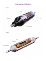
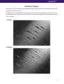
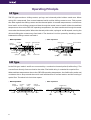
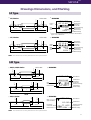
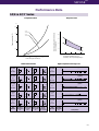
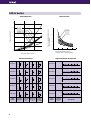
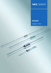
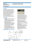
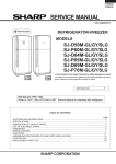
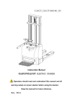
SEFUSE
TM
THERMAL CUTOFF
8th Edition
Cutaway View of SEFUSETM
SF Type
SF Type
SEFUSE
TM
Contents
Introduction ..................................................................................................................................... 4
Features ............................................................................................................................................ 4
Applications ..................................................................................................................................... 4
Product Types .................................................................................................................................. 5
Operating Principle ......................................................................................................................... 6
Drawings, Dimensions and Marking ............................................................................................. 7
Standard Ratings ............................................................................................................................. 8
Performance Data .......................................................................................................................... 11
Lead Cutting and Taping ............................................................................................................... 15
Cautions ......................................................................................................................................... 16
Application Examples ................................................................................................................... 21
Series
Rated Current
Rated Functioning Temperature
Page
SF / E
10 Aa.c.
73 ˚C to 240 ˚C
8
SF / Y
15 Aa.c.
73 ˚C to 24C ˚C
8
SM / A
2 Aa.c.
70 ˚C to 187 ˚C
9
SM / B
1 Aa.c.
100 ˚C to 150 ˚C
9
SM / G
0.5 Aa.c.
100 ˚C to 150 ˚C
9
Select optimum series according to temperature and electrical ratings.
Please be sure to read the "Cautions" on pages 16 through 19 before using.
3
Introduction
NEC's SEFUSETM is a compact and reliable thermal cutoff designed to protect domestic electrical
appliances and industrial electrical equipment from fire. Cutoff occurs and an electrical circuit opens
when ambient temperature increases to an abnormal level.
Two NEC SEFUSE types are available. The SF type uses an organic thermosensitive material as the
thermal pellet and its operating temperature range is 73 ˚C to 240 ˚C.
The SM type uses a fusible alloy and has an operating range of 70 ˚C to 187 ˚C.
SEFUSE is manufactured in Japan and thailand, and both factories are ceritified by the International Standards Organization (lSO) for the ISO9001 quality standard. The factory in Japan is certified for the ISO 14001 environmental management system too.
Features
●
Compact, durable, and reliable by resin-sealed construction
●
One shot operation
●
Excellently sensitive to abnomal temperature rise and high accuracy in operation
●
Stable and precise operation
●
Wide choice of types to suit the application (SF or SM)
●
Meets many international safety standards
Applications
●
Electric heaters, electric irons, hair dryers, electric blankets
●
Air conditioners, compressors, washing machines, electric fans, ventilation fans, electric pencil
sharpeners, electric sewing machines, copy machines, various motors
●
Color televisions, LCD televisions, stereo equipment, Iamps, fluorescent lamps, electric shavers,
video and audio cassette recorders, various transformers, AC adaptor, charger, Battery packs
●
Rice cookers, microwave ovens, electric refrigerators, electric water pots, toasters, electric pans,
coffee makers, juicers, dish dryers
●
Gas boilers, gas heaters, oil heaters, cameras, telephone switching (PBX) equipment
Safety standards
Japan
UL
CSA
VDE
BEAB
Electrical Appliance and
Material Control Law of
Japan
Underwriters Laboratories
Inc. (U. S. A.)
Canadian Standards
Association
Verband Deutscher
Elektrotechniker e.V.
(F. R. G.)
British Electrotechnical
Approvals Board
4
SEFUSE
TM
Product Types
The SF type uses an organic thermosensitive pellet inside a metal case. It features a large cutoff
(rated) current of 10 A or 15 A.
The SM type uses a fusible alloy inside a ceramic case. It has a cutoff(rated)current of 0.5 A, 1 A or
2 A. Because of its insulated case, the SM type can be attached directly where temperature detection is required.
●
SF Type
●
SM Type
5
Operating Principle
SF Type
THE SF type contains a sliding contact, springs, and a thermal pellet inside a metal case. When
spring B is compressed, firm contact between lead A and the sliding contact occurs. This presses
two disks against the sliding contact and the thermal pellet. At normal temperatures, current flows
from lead A to the sliding contact and then through the metal case to lead B. When the ambient
temperature rises to the SEFUSE operating temperature, the heat transferred through the metal
case melts the thermal pellet. When the thermal pellet melts, springs A and B expand, moving the
disk and sliding the contact away from lead A. The electrical circuit is opened by breaking contact
between the sliding contact and lead A.
●
Before Operation
●
Ceramic
Spring B
After Operation
Metal Case
Thermal Pellet
,,
,,
Sealing
Compound
Lead A
Ceramic Pipe
Spring A
Sliding
Contact
Disks
Thermal Pellet
,,,
,,,
Spring B
Lead B
Metal Case
Sliding
Contact
Spring A
Disks
SM Type
In the SM type, Ieads A and B are connected by a conductive thermal pellet (fusible alloy). The
current flows directly from one lead to the other. The fusible alloy is coated with a special flux.
When ambient temperature rises to the SEFUSE operating temperature, the fusible alloy melts and
condenses into a drop around the end of each lead because of surface tension and the coating of
special flux. The electrical circuit then opens.
Before Operation
Sealing
Compound
Lead
●
Ceramic
Case
Fusible
Alloy
,,,
Flux
6
After Operation
Sealing
Compound
Fusible Alloy
Lead
Lead
,
●
Flux
,
Lead
SEFUSE
TM
Drawings Dimensions, and Marking
SF Type
Unit : mm
11
20(35)
●
φ 1.0
φ 4.2
SF/E Series
φ 1.0
●
MARKING
Factory ∗
Code
SEFUSE
SF139E
T f 1 4 2˚C
10A
250V ~
MITI
Approved
Mark
35
66(81)
Brand Name
Part Number
Production
Control No.
Rated Functioning
Temperature
Rated Current
Rated Voltage
∗ Factory Code represents the factory location as shown below.
Japan : none, Thailand : B
Unit : mm
●
MARKING
SEFUSE
SF139Y
φ 1.3
φ 4.2
SF/Y Series
φ 1.3
●
Maker
Mark
11
20(35)
MITI
Approved
Mark
35
66(81)
139˚C
15A
250V
Brand Name
Part Number
Production
Control No.
Rated Functioning
Temperature
Rated Current
Rated Voltage
Note: The dimensions for long lead devices are in parentheses.
SM Type
Unit : mm
38(68)
9
●
MARKING
φ 0.6
φ 2.5
SM/A, SM/B Series
φ 0.6
●
38(68)
SEFUSE
Brand Name
SM126A0
Part Number
Production
Control No.
Rated Functioning
Temperature
85(145)
φ 0.53
φ 0.53
φ 2.0
SM/A
MITI
Approved Mark
Rated Current
39.5(69.5)
6
T f 1 3 1˚ C
2A 250V ~
Rated Voltage
39.5(69.5)
85(145)
SM/B
SM/G Series
40(70)
5
85(145)
φ 0.53
φ 1.6
●
φ 0.53
●
40(70)
MARKING
MITI
Approved Mark
Production
Control No.
Rated Current
SEFUSE
Brand Name
110 G0
Part Number
Tf 115˚C
0.5 A 2 5 0 V ~
Rated Functioning
Temperature
Rated Voltage
Note: The dimensions for long lead devices are in parentheses.
7
Standard Ratings
SF Type
●
SF/E Series
Part 1) Rated Functioning Operating
Temperature
Number
Temperature
TF, Tf
SF 70E
73 ˚C
70±2 ˚C
SF 76E
77 ˚C
76± 204 ˚C
3
1
TH
Th
TC
45 ˚C
150 ˚C
51 ˚C
150 ˚C
TM
Tm
Safety Standard
Rated
Rated
Current Voltage
UL
CSA
VDE
BEAB
5)
SF 91E
94 ˚C
91± 2 ˚C
66 ˚C
150 ˚C
SF 96E
99 ˚C
96±2 ˚C
71 ˚C
150 ˚C
SF109E
113 ˚C
109± 231 ˚C
84 ˚C
150 ˚C
SF119E
121 ˚C
119±2 ˚C
94 ˚C
150 ˚C
SF129E
133 ˚C
129±2 ˚C
104 ˚C
159 ˚C
10 A
250 V
SF139E
142 ˚C
139±2 ˚C
114 ˚C
159 ˚C
(AC)
(AC)
SF152E
157 ˚C
152±2 ˚C
127 ˚C
172 ˚C
SF169E
172 ˚C
169± 213 ˚C
144 ˚C
189 ˚C
SF188E
192 ˚C
188± 231 ˚C
164 ˚C
300 ˚C
SF214E
216 ˚C
214± 213 ˚C
189 ˚C
350 ˚C
SF226E
227 ˚C
226± 213 ˚C
190 ˚C
SF240E
240 ˚C
237±2 ˚C
190 ˚C
2)
3)
E71747
4)
LR
52330
6778.2
–1171
–0002
6778.2
–4510
–1008
2)
350 ˚C
made in
Japan
made in
Thailand
33–312
33–835
33–331
33–834
33–332
33–833
33–333
33–832
33–334
33–831
33–335
33–830
C0632
33–336
33–886
33–549
33–827
33–354
33–828
Note : 1) Part numbers are for standard lead devices. For long leads, add the number “–1” at the end of part number.
2) The maximum temperature limit of SF226E is partially approved as shown below.
TM.Tm
UL
CSA
VDE
BEAB
SF226E
240˚C ∗
330˚C
300˚C
300˚C
* Under application to increase to over 300˚C
3) The additional electrical ratings are recognized by UL and CSA as follows.
UL : 277 Vac / 15 Aac (Resistive), 240 Vac / 15 Aac (Resistive), 120 Vac / 15 Aac (Resistive, Inductive)
CSA : 250 Vac max. / 15 Aac max. (Resistive, Inductive)
4) SF169E, SF188E, SF214E, SF226E and SF240E are also UL-recognized of optional CH-rating
(Conductive Heat Aging Test).
5) The VDE recognized file number had been changed in February 1998. The number in parentheses are previous
file number.
●
SF/Y Series
Part
Number
1)
Rated Functioning
Temperature
Operating
Temperature
Rated Current
Rated Voltage
SF 70Y
73 ˚C
70± 2 ˚C
SF 76Y
77 ˚C
76± 204 ˚C
SF 91Y
94 ˚C
91± 231 ˚C
SF 96Y
99 ˚C
96± 2 ˚C
SF109Y
113 ˚C
109± 231 ˚C
SF119Y
121 ˚C
119± 2 ˚C
SF129Y
133 ˚C
129± 2 ˚C
SF139Y
142 ˚C
139± 2 ˚C
SF152Y
157 ˚C
152± 2 ˚C
SF169Y
172 ˚C
169± 213 ˚C
33–335
SF188Y
192 ˚C
188± 231 ˚C
33–336
SF214Y
216 ˚C
214± 213 ˚C
33–549
SF226Y
227 ˚C
226± 213 ˚C
SF240Y
240 ˚C
237± 2 ˚C
33–312
33–331
33–332
33–333
15 A (AC)
250 V (AC)
Note : 1) Part numbers are for standard lead devices. For long leads, add the number “–1” at the
end of part number.
8
Safety Standard
33–334
33–354
SEFUSE
TM
SM Type
#) The VDE recognized file number had been changed in February 1998. The number in parentheses are previous
file number.
●
SM/A Series
Part 1) Rated Functioning Operating
Temperature
Number
Temperature
TF, Tf
SM065A0
70 ˚C
65± 2 ˚C
TH
Th
TC
40 ˚C
80 ˚C
TM
Tm
Rated
Rated
Current Voltage
Safety Standard
UL
CSA
VDE
BEAB
33–528
#)
SM095A0
100 ˚C
95± 250 ˚C
65 ˚C
115 ˚C
SM110A0
115 ˚C
110± 2 ˚C
80 ˚C
125 ˚C
SM126A0
131 ˚C
126± 2 ˚C
96 ˚C
140 ˚C
2A
250 V
SM130A0
135 ˚C
130± 2 ˚C
100 ˚C
145 ˚C
(AC)
(AC)
SM145A0
150 ˚C
145± 2 ˚C
115 ˚C
160 ˚C
SM164A0
169 ˚C
164± 232 ˚C
133 ˚C
180 ˚C
SM182A0
187 ˚C
182± 2 ˚C
152 ˚C
195 ˚C
6778.2
–1171
–0001
E71747 LR52330
33–466
33–472
C0600
( )
6778.2
–4510
–1007
33–467
33–468
33–470
33–556
Note : 1) Part numbers are for standard devices. For long leads, change the last number from 0 to 1.
●
SM/B Series
TH
Th
TC
Part 1) Rated Functioning Operating
Temperature
Number
Temperature
TF, Tf
SM095B0
100 ˚C
95±250 ˚C
65 ˚C
115 ˚C
SM110B0
115 ˚C
110±2 ˚C
80 ˚C
125 ˚C
SM126B0
131 ˚C
126±2 ˚C
96 ˚C
140 ˚C
SM130B0
135 ˚C
130±2 ˚C
100 ˚C
145 ˚C
SM145B0
150 ˚C
145±2 ˚C
115 ˚C
160 ˚C ∗
TM
Tm
Rated
Rated
Current Voltage
Safety Standard
UL
CSA
VDE
BEAB
#)
1A
250 V
(AC)
(AC)
E71747 LR52330
6778.2
–1171
–0004
6778.2
–4510
–1009
33–466
33–472
C0557
( )
33–467
33–468
Note : 1) Part numbers are for standard devices. For long leads, change the last number from 0 to 1.
∗ Tm of SM145B for CSA is 155 ˚C
●
SM/G Series
Part 1) Rated Functioning Operating
Temperature
Number
Temperature
TF, Tf
SM095G0
100 ˚C
95±250 ˚C
TH
Th
TC
65 ˚C
115 ˚C
SM110G0
115 ˚C
110±2 ˚C
80 ˚C
125 ˚C
SM126G0
131 ˚C
126±2 ˚C
96 ˚C
140 ˚C
SM130G0
135 ˚C
130±2 ˚C
100 ˚C
145 ˚C
SM145G0
150 ˚C
145±2 ˚C
115 ˚C
155 ˚C
TM
Tm
Rated
Rated
Current Voltage
Safety Standard
UL
CSA
VDE
BEAB
#)
2)
2)
0.5 A
250 V
(AC)
(AC)
E71747 LR52330
6778.2
–1171
–0003
6778.2
–4510
–1005
( )
33–466
33–472
C0743
33–467
33–468
Note : 1) Part numbers are for standard lead devices. For long leads, change the last number from 0 to 1.
2) The additional electrical ratings are recognized by UL as follows.
SM095G : DC 50 V / 3 A,
SM110G, SM126G, SM130G, SM145G : DC 50 V / 5 A
9
Definition of Terms
●
Rated Functioning Temperature
Rated functioning temperature is the operating temperature of thermal cutoffs, measured using
the method specified in the safety standard. In present E.A.M.C. (Electrical Appliance and Material
Control) Law of Japan, Valid until June 2001, the operation should be within the specified operating temperature range of ± 7˚C. In various standards such as UL, CSA, VDE, BEAB and new
E.A.M.C. Low of Japan, which comply with the IEC standard, it is called the rated functioning
temperature, and should operate within the prescribed temperature range of +0/–10 ˚C.
It is represented by the symbol TF in the UL standard, and by the symbol Tf in the CSA, VDE and
BEAB and new E.A.M.C. standards.
In SEFUSE, a temperature that complies with both standards is set as the rated functioning
temperature, and is indicated on the body of the thermal cutoff.
●
Operating Temperature
Operating temperature is the actual operating temperature range when the thermal cutoff is
made to operate inside a constant temperature oven whose temperature is raised at the rate of
1 ˚C/min. while a detection current of 100 mA or lower is applied.
The operating temperature is a standard set by NEC and is not specified by a safety standard.
●
TH, Th, Tc (Holding Temperature)
Holding temperature is the maximum temperature at which, when applying a rated current to
the thermal cutoff, the state of conductivity is not changed during specified time not hess than
168 hours (1 week).
It is represented by the symbol TH in the UL standard, Th in the CSA standard, and Tc in the VDE,
BEAB and new E.A.M.C. standards.
●
TM, Tm (Maximum Temperature Limit)
Maximum temperature limit is the temperature up to which thermal cutoffs will not change its
state of cutoff without impairing.
It is represented by the symbol TM in the UL standard and by Tm in the CSA, VDE, BEAB and new
E.A.M.C. standards.
●
Rated Current
Reted current is the maximum current that thermal cutoffs allow to carry and are able to cutoff
the circuit in safety.
●
Rated Voltage
Reted voltage is the maximum voltage that is allowed to apply to the circuit in wich the thermal
cutoff is used.
10
SEFUSE
TM
Performance Data
SF/E & SF/Y Series
Temperature Rise
Response Time
(˚C)
40
30
Time for opening after immersion
into oil (seconds)
Temperature Rise (˚C)
SF/E
SF/Y
20
10
40
30
20
10
0
5
5
10
15
10
20
30
40
Temperature Difference (˚C)
(oil temp. minus operating temp.)
20
Pass-through Current (A)
Initial Characteristics
SF169E
&
SF169Y
SF139E
&
SF139Y
SF109E
&
SF109Y
SF96E
&
SF96Y
SF70E
&
SF70Y
Part
Number
High Temperature Storage Test
169
106
2.0
1.5
168
105
1.5
1.0
SF169E
E
104
1.0
0.5
Y
140
106
2.0
1.5
E
105
138
104
1.0
0.5
Y
112
106
2.0
1.5
E
1.0
110
104
1.0
0.5
Y
97
106
2.0
1.5
E
96
105
1.5
1.0
1.0
0.5
Y
71
106
2.0
1.5
E
70
105
1.5
1.0
Operating
Temperature
(˚C)
1.0
(MΩ)
(kV)
–2
@76˚C
+2
&
0
–2
SF70E
@50˚C
+2
&
0
SF70Y
Y
–2
Internal
Resistance
(mΩ/25 mm)
Part
Operating
Number Temperature
0.5
Insulation
Withstand Voltage
Resistance after
after Operation
Operation
0
SF96Y
1.0
@89˚C
+2
&
SF96E
95
104
–2
SF109Y
104
69
0
SF109E
105
@119˚C
+2
&
SF139Y
111
1.5
0
–2
SF139E
139
1.5
&
SF169Y
167
@140˚C
+2
Change of
(˚C)
0
10
100
1,000
10,000
Time (Hours)
Note : The values following @ are the storage temperature.
11
SM/A Series
Temperature Rise
Response Time
(˚C)
6
4
,
,
,
,
,
,
,
,
,, ,,,,
,,,,,,,,,,,,,,
,,,,,,,,
,,
30
SM095A0
SM110A0
SM126A0
SM130A0
SM145A0
Time for opening after immersion
into oil (seconds)
Temperature Rise (˚C)
5
3
2
1
SM095A0
SM110A0
SM126A0
SM130A0
SM145A0
20
10
0
0
1
2
Initial Characteristics
SM130A0
SM126A0
SM110A0
SM095A0
30
40
50
High Temperature Storage Test
106
3.0
3.4
145
105
2.0
3.0
144
104
1.0
2.6
–5
131
106
3.0
4.4
+5
130
105
2.0
4.0
129
104
1.0
3.6
–5
127
106
3.0
4.4
+5
126
105
2.0
4.0
125
104
1.0
3.6
–5
111
106
3.0
4.4
+5
110
105
2.0
4.0
109
104
1.0
3.6
–5
99
106
3.0
11
+5
98
105
2.0
9
97
104
1.0
7
Withstand Voltage
Operating
Internal
Resistance after
after Operation
Temperature
Resistance
Operation
(kV)
(˚C)
(mΩ/25 mm)
(MΩ)
@125˚C
+5
146
SM145A0
SM130A0
SM126A0
SM110A0
SM095A0
0
@110˚C
0
@106˚C
0
@90˚C
0
@75˚C
0
–5
Insulation
Part
Number
20
Temperature Difference (˚C)
(oil temp. minus operating temp.)
Pass-through Current (A)
SM145A0
10
Part
Number
Change of
Operating
Temperature
(˚C)
0 10
100
1,000
10,000
Time (Hours)
Note : The values following @ are the storage temperature.
12
SEFUSE
TM
SM/B Series
Temperature Rise
Response Time
10
9
SM095B0
SM110B0,SM126B0,SM130B0
SM145B0
,
,
,
,,,,,,,,
,
,
,
,
,
,
,,,,,,,,,,,,
, , ,,
30
Time for opening after immersion
into oil (seconds)
Temperature Rise (˚C)
8
7
6
5
4
3
2
1
20
10
0
0
1
2
3
SM095B0
SM110B0
SM125B0
SM130B0
SM145B0
10
20
30
40
50
Temperature Difference (˚C)
(oil temp. minus operating temp.)
Pass-through Current (A)
Initial Characteristics
SM145B0
SM130B0
SM126B0
SM110B0
SM095B0
High Temperature Storage Test
146
106
3.0
4.0
145
105
2.0
3.5
144
104
1.0
3.0
–5
130
106
3.0
4.7
+5
129
105
2.0
4.6
128
104
1.0
4.5
–5
127
106
3.0
4.8
+5
126
105
2.0
4.6
125
104
1.0
4.4
–5
112
106
3.0
4.7
+5
111
105
2.0
4.6
110
104
1.0
4.5
98
106
3.0
9.5
+5
97
105
2.0
9.0
0
96
104
1.0
8.0
SM145B0
SM130B0
SM126B0
SM110B0
Withstand Voltage
Operating
Internal
Resistance after
after Operation
Temperature
Resistance
Operation
(kV)
(˚C)
(mΩ/25 mm)
(MΩ)
0
@110˚C
0
@106˚C
0
@90˚C
0
–5
SM095B0
@75˚C
–5
Insulation
Part
Number
@125˚C
+5
Part
Number
Change of
Operating
Temperature
(˚C)
0 10
100
1,000
10,000
Time (Hours)
Note : The values following @ are the storage temperature.
13
SM/G Series
Temperature Rise
,
,
,
,
,
,,,,,,,,,,
,,,,,,,,,,,,
,,,,,,,,,,,,,,,,,,
, , ,, ,
SM095G0
Time for opening after immersion
into oil (seconds)
Temperature Rise (˚C)
10
Response Time
SM110G0
SM125G0
SM130G0
SM145G0
5
30
SM095G0
SM110G0
SM126G0
SM130G0
SM145G0
20
10
0
0
1
2
3
Initial Characteristics
SM130G0
SM126G0
SM110G0
SM095G0
106
3.0
5.0
145
105
2.0
4.0
144
104
1.0
3.0
–5
131
106
3.0
6.0
+5
130
105
2.0
5.0
129
104
1.0
4.0
–5
127
106
3.0
6.0
+5
126
105
2.0
5.0
125
104
1.0
4.0
–5
112
106
3.0
6.0
+5
111
105
2.0
5.0
110
104
1.0
4.0
–5
99
106
3.0
13.0
+5
98
105
2.0
11.0
97
104
+5
SM145G0
SM130G0
SM126G0
SM110G0
SM095G0
9.0
Withstand Voltage
Operating
Internal
Resistance after
after Operation
Temperature
Resistance
Operation
(kV)
(˚C)
(mΩ/25 mm)
(MΩ)
@125˚C
0
@110˚C
0
@106˚C
0
@90˚C
0
@75˚C
0
–5
Insulation
Part
Number
30
High Temperature Storage Test
146
1.0
20
Temperature Difference (˚C)
(oil temp. minus operating temp.)
Pass-through Current (A)
SM145G0
10
Part
Number
Change of
Operating
Temperature
(˚C)
0 10
100
1,000
10,000
Time (Hours)
Note : The values following @ are the storage temperature.
14
SEFUSE
TM
Lead Cutting and Taping
NEC will perform lead cutting or taping as requested by customers.
K
Applicable Products
●
SF type : SF ∗ ∗ ∗ E (only for lead cutting), SF ∗ ∗ ∗ E-1
Does not apply to the SF/Y series.
●
K
SM ∗ ∗ ∗ A0, SM ∗ ∗ ∗ B0, SM ∗ ∗ ∗ G0 (short lead type)
SM type :
Taping
reel
φ 285
Z
φ 75
P
φ 30
R
R
t
89
L1
S
L2
T
W
SF type: 2000 pcs/reel
SM type: 2500 pcs/reel
S
T
(75)
(Unit : mm)
W
P
L1 - L2
52±2
63±2 5±0.5 2.0
67±2
K
T
Z
R
t
S
6±1
2.0
0.5
3.2
0.8
Lead Cutting
●
SF Type
L1 : 7 to 30
L2 : 7 to 33 (mm)
L1
●
L2
SM Type
L1, L2 : 7 to 33 (mm)
L1
L2
For more information on dimensions not described in diagrams above, please call NEC.
15
Cautions
This section describes cautions designed to protect the performance of the thermal cutoff. Be sure
to read and fully understand these cautions.
To obtain full performance from the thermal cutoff, it is necessary for the customer to
appropriately store the thermal cutoff, design appropriate circuits for the application, and
perform evaluations, mounting and testing as necessary. Problems arising from the
inappropriate execution of the above are the responsibility of the customer, and NEC declines
any and all responsibility.
Design Cautions
●
Do not use this device for and purpose other than as a thermal cutoff.
The thermal cutoff is designed to detect abnormal rises in temperature and break circuits if
needed. It is not a current fuse that cuts excess current. If used as a current fuse, the SEFUSE
may malfunction.
●
Do not use this device in aerospace equipment, aeronautical equipment, nuclear reactor control
systems, Iife support equipment or systems, transportation machinery engine control or safetyrelated equipment.
This device is designed for use in household electric appliance, office automation equipment,
audio and video equipment, computer communications equipment, test and measurement
equipment, personal electronic equipment and transportation equipment (excluding engine
control).
●
The customer should select the proper thermal cutoff device, mounting location, and mounting
method as appropriate for each application.
Verify whether the chosen selections are appropriate by repeatedly testing the final design for
thermal cutoff under normal conditions as well as under predicted maximum abnormal
conditions.
●
Make designs so that the temperature of the body of the thermal cutoff does not exceed the
temperatures shown in Table 1.
If, the temperature is exceeded on a regular basis, the thermal cutoff may start operating only at
temperature lower than the normal operating temperature. Malfunctions may also occur. Even
if the thermal cutoff's operating temperature is exceeded, it may malfunction.
16
SEFUSE
SM Type
TM
SF Type
Type
Body
Temperature
Type
Body
Temperature
SM065A
SM095A, B, G
SM110A, B, G
SM126A. B. G
SM130A, B, G
SM145A, B, G
SM164A
SM182A
45 ˚C
75 ˚C
90 ˚C
106 ˚C
110 ˚C
125 ˚C
140 ˚C
140 ˚C
SF 70E, Y
SF 76E, Y
SF 91E, Y
SF 96E, Y
SF109E, Y
SF119E, Y
SF129E, Y
SF139E, Y
SF152E, Y
SF169E, Y
SF188E, Y
SF214E, Y
SF226E, Y
SF240E, Y
50 ˚C
56 ˚C
71 ˚C
76 ˚C
89 ˚C
99 ˚C
109 ˚C
119 ˚C
132 ˚C
140 ˚C
140 ˚C
140 ˚C
140 ˚C
140 ˚C
Table 1
●
The body temperature of the thermal cutoff becomes higher as current passes through and
might rise higher than the ambient operating temperature (see test data). The temperature may
rise even higher depending on the mounting method and other conditions. Therefore, after mounting the thermal cutoff under the same conditions you would use for the actual application, work
the final product and measure the body temperature of the thermal cutoff.
●
Use the thermal cutoff with a voltage and current level lower than the rated level.
If the thermal cutoff is used with a voltage or current level higher than the rated level, contacts
may melt in the SF type, causing the fuse to malfunction. In the SM type, the body of the thermal
cutoff may be destroyed.
●
Do not use the thermal cutoff in water, organic solvents or other liquids, or environments
containing sulfurous acid gas, nitrous acid gas, or high humidity. Doing so will cause
deterioration of the sealing resin, the thermal cutoff may operate at lower than operating
temperature, or any other malfunctions may occur. Also, the thermal cutoff may not operate
even if its operating temperature is exceeded.
17
Lead wire process
●
When bending the lead wire, in order to protect the resin seal from excessive pressure, secure
the lead wire cIose to the case and bend the part beyond the secured section.
3 mmor more
,,,,,
,,
,,,,,
,,
,,,,,
,
,,,,,
,
Secured
Secured
The lead wire should be bent at a distance 3 mm or more from the body of the fuse, and should
not be twisted.
●
The tensile strength applied to the lead wire should be 5 kg or less for the SF type, and 1 kg or
less for the SM type.
●
The strength applied to the body of the thermal cutoff should be 10 kg or less for the SF type, and
5 kg or less for the SM type.
SF(10 kgf)
SM(5 kgf)
φ 0.8 steel wire
In the case of an SF type, deformation of the case may change the location of the moving
electrode during operation and may cause the thermal cutoff to operate only at temperatures
lower than the normal operating temperature range. The thermal cutoff also may not operate
even if the thermal cutoff's operating temperature is exceeded.
Mounting
SEFUSE can be mounted by soldering, caulking, or welding.
●
If soldering, note that the thermal cutoff may not function because of excessive solder
temperature.
To prevent such malfunctions, for example, holding the lead new the case by a tool is effective
for allowing the heat to escape, and the soldering should be done in short interval.
Another effective method is to use a lower solder temperature and to solder at a location that is
distant from the case.
●
If caulking or welding, be careful to keep the resistance value of the connecting section low.
If the connecting section has a high resistance value, the passing current may generate an
abnormally high temperature that will cause the thermal cutoff to operate (break the circuit).
18
TM
SEFUSE
●
It is recommended that the connecting position at the lead of resign-sealed side should be 5 mm
or more from the body of the thermal cutoff.
5 mm or more
●
Connecting Position
5 mm or more
5 mm or more
Connecting Position
After mounting the thermal cutoff, be careful not to apply force that may pull, push or twist the
lead wires.
●
If using an SF type thermal cutoff, be sure not to make the lead on the resin-sealed side touch
the case. This would cause the current to flow from the lead on the resin-sealed side to the
opposite lead so that the thermal cutoff cannot break the circuit.
Note that the body of the SF type is the same in potential as the circuit. Therefore, it must be
electrically isolated from the other metalic part.
Storage
●
The body and lead A of SF type, and the leads of SM164A and SM182A are silver-plated. Therefore, these parts may discolor because of sulfuration. In the case, the marking of the body wiII
become difficult to discriminate or the solder-abiIity of lead wiII decline. To avoid this, the SEFUSE
should not keep around materials (such as cardboard or rubber, etc.) which generate sulfurous
acid gas.
●
When the SEFUSE have to be storaged in a cardboard box, the SEFUSE's packs should be put
into other bags (such as polyethylene) and make sure the packs seal.
Recommendation
●
Be careful when mounting the thermal cutoff because external force, heat, or a harmful atmosphere (containing excessive humidity or sulfurous acid gas) may damage the characteristics of
the thermal cutoff. If applicable, it is recommended to warn general consumers who are not
aware of the usage cautions for the thermal cutoff not to mount, remove or replace the thermal
cutoff through a note to this effect in the user's manual and other related material.
If you desire any clarifications or explanations regarding these cautions, please call an NEC
sales representative.
The values contained in this document were obtained under certain testing conditions at NEC.
They are not guaranteed and are for reference only.
19
The information in this document is based on documents issued in February, 1999 at the latest. The
information is subject to change without notice. For actual design-in, refer to the latest publications of
data sheet, etc., for the most up-date specifications of the device.
No part of this document may be copied or reproduced in any form or by any means without the prior
written consent of NEC Corporation. NEC Corporation assumes no responsibility for any errors which
may appear in this document.
NEC Corporation does not assume any liability for infringement of patents, copyrights or other intellectual property rights of third parties by or arising from use of a device described herein or any other
liability arising from use of such device. No license, either express, implied or otherwise, is granted
under any patents, copyrights or other intellectual property rights of NEC Corporation or others.
While NEC Corporation has been making continuous effort to enhance the reliability of its electronic
components, the possibility of defects cannot be eliminated entirely. To minimize risks of damage or
injury to persons or property arising from a defect in an NEC electronic component, customer must
incorporate sufficient safety measures in its design, such as redundancy, fire-containment, and antifailure features.
NEC devices are classified into the following three quality grades:
"Standard", "Special", and "Specific". The Specific quality grade applies only to devices developed based
on a customer designated "Quality assurance program" for a specific application. The recommended
applications of a device depend on its quality grade, as indicated below. Customers must check the
quality grade of each device before using it in a particular application.
Standard: Computers, office equipment, communications equipment, test and measurement equipment, audio and visual equipment, home electronic appliances, machine tools, personal electronic equipment and industrial robots
Special: Transportation equipment (automobiles, trains, ships, etc.), traffic control systems, anti-disaster
systems, anti-crime systems, safety equipment and medical equipment (not specifically designed for life support)
Specific: Aircrafts, aerospace equipment, submersible repeaters, nuclear reactor control systems, life
support systems or medical equipment for life support, etc.
The quality grade of NEC devices is "Standard" unless otherwise specified in NEC's Data Sheets or Data Books.
If customers intend to use NEC devices for applications other than those specified for Standard quality grade,
they should contact an NEC sales representative in advance.
Anti-radioactive design is not implemented in this product.
20
SEFUSE
TM
Application Examples
Electric Iron
Transformer
LCD Television
Rice Cooker
Remark(∗)
For the purpose of photography, the
insulation tube of the thermal cutoff
has been removed.
In reality, the thermal cutoff is covered
by the insulation tube.
Inverter for EL Light Drive
19
21
For further information, please contact:
NEC Corporation
NEC Building
7-1, Shiba 5-chome, Minato-ku
Tokyo 108-8001, Japan
Tel: 03-3798-6148
Fax: 03-3798-6149
[North & South America]
NEC Electronics Inc.
Electron Components
2880 Scott Boulevard, M/S SC900
P.O.Box 58062
Santa Clara, CA 95052-2554, U.S.A.
Tel: 408-588-6160
Fax: 408-588-6130
(Regional Sales Offices)
Central Region
Greenspoint Tower
2800 West Higgins
Road Suite 765
Hoffman Estates, IL 60195, U.S.A.
Tel: 708-519-3930
Fax: 708-519-9329
Northern California Region
3033 Scott Blvd.
Santa Clara, CA 95054, U.S.A.
Tel: 408-588-5100
Fax: 408-588-5134
Eastern Region
901 N. Lake Destiny Drive
Suite 320
Maitland, FL 32751, U.S.A.
Tel: 407-875-1145
Fax: 407-875-0962
Western Region
One Embassy Centre
9020 S.W. Washington
Square Road
Suite 400
Tigard OR 97223, U.S.A.
Tel: 503-671-0177
Fax: 503-643-5911
Document No.
Date Published
©
[Asia & Oceania]
NEC Electronics Hong Kong Ltd.
12/F, Cityplaza 4, 12
Taikoo Wan Road, Hong Kong
¨ 2886-9318
Tel:
Fax: 2886-9022, 2886-9044
Seoul Branch
10F, ILSONG Bldg., 157-37,
Samsung-Dong, Kangnam-Ku,
Seoul, The Republic of Korea
Tel: 02-528-0303
Fax: 02-528-4411
Shen-zhen Office
31st, Floor, Shen-zhen International Financial
Bldg. 23 Jian She Road, Shenzhen, China
Tel: 755-2227094
Fax: 755-2256360
Australia Representative Office
303-313 Burwoood Highway
Burwood East, Victoria 3151,Australia
Tel: 03-98878012/98878013
Fax: 03-98878014
NEC Electronics Taiwan Ltd.
7F, No. 363 Fu Shing North Road
Taipei, Taiwan, R.O.C.
Tel: 02-2719-2377
Fax: 02-2719-5951/5936
NEC Electronics Singapore Pte., Ltd.
101 Thomson Road
#04-02/05 United Square
Singapore 307591
Tel: 65-253-8311
Fax: 65-250-3583
EM0060EJ8V1SG00 (8th edition)
February 1999 M
1989 (1997)
Printed in Japan