1
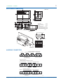
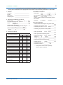
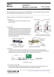
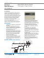
<<Contents>> <<Index>> Model MG8G (General Purpose) Paramagnetic Oxygen Analyzer General Specifications GS 11P03A03-01E GENERAL The Model MG8G Paramagnetic Oxygen Analyzer measures the concentration of oxygen based on the fact that a magnet attracts gaseous oxygen. The sensor employs a magnetic proportional flow rate system, which has been developed based on our long and field-proven experience, providing improved and advanced performance. Whereas Zirconia Oxygen Analyzers cannot measure oxygen in flammable gas mixtures, the MG8G can measure oxygen concentration in flammable gas mixtures. The converter is microprocessor based, to provide ease of use and self-diagnostics. It can be used together with a sampling unit to measure oxygen in high temperature, high pressure, high dusty, or high-humidity process gas mixtures. • FEATURES • • • Long-life Sensor Regardless of Measurement Gas Types A clean auxiliary gas (N2), not process gas, is always flowing past the detection unit sensor. Therefore, a stabilized output can be obtained for a long period uninfluenced by contamination in the process gas or by corrosive gas. 90% Response within 3 sec Since a thermistor having high sensitivity and a high speed of response directly detects variations in an auxiliary gas, a response can be derived instantaneously. Moreover, since the thermistor does not come into contact with the process gas, a long service life and stable high-speed response can be obtained. Structure with No Movable Parts Having no movable parts, the MG8G is excellent in seismic-proof property and shock resistance. Since the material along the process-gas flow path is made of JIS SUS316 stainless steel, it has excellent durability • • • Interference-gas Compensation Function A flammable gas (such as H2) has a little magnetism, although their magnetism is very low compared to oxygen. This causes error in a paramagnetic oxygen analyzer to result in error. However, the MG8G has a function to compensate for one type of interfering gas (or multi component gas having constant of its mixture ratio) using the differences in gas densities. Easy Operation with Large Display The large display can display oxygen concentration, thermostat temperature of the detector, cell output, and so on. The analog bar graphs can indicate the analog output statuses for each range. One-touch Calibration, Automatic Calibration for Labor-saving Calibration is enabled by only pressing the calibration button after turning on the calibration gas (zero/span gas) flow. Further, an automatic calibration mode is available if you need. Multiple Self-diagnosis Functions Since five types of errors including cell error, analog error, and temperature error are clearly displayed, appropriate actions can be immediately taken. BASIC SYSTEM CONFIGURATION 180 kPa (Flow rate: approx. 35 ml / min) Gas pressure regulator Gas pressure meter Needle valve * Gas pressure 0.3~0.5MPa regulator (G7033XF) Auxiliary gas N2 Filter Flowmeter MG8G Analog output (0 to 1V DC) (4 to 20 mA DC) Contact output (abnormal) (maintenance) (range selection answerback) (Hi / Lo alarm) Needle valve Gas outlet Needle valve Measurement gas Gas flow: 200 ml/min ±10% Pre-treatment unit Feed Drain Gas pressure regulator Gas pressure regulator Steam inlet Steam outlet Zero gas N2 Span gas O2+N2 Power supply F01.ai * Gas pressure ragulator for auxiliary gas is supplied as standard accessory with oxygen analyzer. Yokogawa Electric Corporation 2-9-32, Nakacho, Musashino-shi, Tokyo, 180-8750 Japan Tel.: 81-422-52-5617 Fax.: 81-422-52-6792 GS 11P03A03-01E ©Copyright June 2004 4th Edition Nov. 2010 2 <<Contents>> <<Index>> ■STANDARD SPECIFICATIONS Measurement Object: Oxygen concentration in gaseous mixture Measurement System: Paramagnetic system Measurement Range: 0-5 to 0-25 vol%O2 3 ranges can be programmed arbitrarily within the above specified range. Self-diagnostic content: Sensor unit error, Constant temperature chamber error, Analog error, Memory error, Calibration coefficient error Analog output signal: 4 to 20 mA DC (load resistance: Maximum 550 Ω) Contact output: Contact rating; 3 A at 250 V AC or 30 V DC, dry contacts Fail; 1 point, open or closed when error occurs, user configurable Contact is activated when sensor unit error, constant temperature chamber error,analog error, memory error, or calibration coefficient error (when automatic or semiautomatic calibration is enabled) occurs Maintenance status; 1 point, closed during maintenance Range answerback or high/low alarm; 2 points, normally de energized (open) Range answerback or high/low alarm contact output, user selectable Operate solenoid valve: 3 points, Switching between zero and span calibration gas and measured gas. Maximum load; AC 1A Contact input: Input specification;Contact ON: 200 Ω or less, Contact OFF: 100 kΩ or greater Remote range switching; 2 points, Output ranges 1 to 3 can be switched by external contact signal. Calibration start; 1 point, calibration start command by external contact signal. Calibration methods: (1) Automatic calibration at set intervals by internal timer (2) Semiautomatic calibration started by external contact input (3) Manual calibration in the field Calibration gas: Zero gas; N2 gas Note: Zero gas should not contain O2 gas with a concentration equal to or greater than 0.1% of the upper range value. Span gas: Dry air (instrument air O2: 20.95 vol%) or standard gas containing O2 gas with a concentration of 80 to 100 % of the span value (balance nitrogen). Auxiliary gas pressure: N2, 180 kPa (Approx. 35 ml/min) Note: Auxiliary gas should not contain O2 gas with a concentration equal to or greater than 0.1 % of the upper range value. Measurement gas condition: Flow; 200ml/min ±10 %, The gas flow rate may be less than 200 ml/min depending on the composition of the measurement gas. Temperature; 0 to 50°C Humidity; No moisture condensation in the flow path or the sensor. Warm-up time: Approx. 2.5 hours Installation condition: Ambient temperature; -5 to 55°C All Rights Reserved. Copyright © 2007, Yokogawa Electric Corporation Humidity; 10 to 95 %RH (No condensing) Power supply: Power supply Voltage 100 to 115 V AC; Reted voltage range: 100 to 115 V AC Allowable voltage range: 90 to 127 V AC Rated frequency: 50 or 60 Hz Allowable frequency range: 48 to 63 Hz Power supply Voltage 200 to 240 V AC; Reted voltage range: 200 to 240 V AC Allowable voltage range: 180 to 264 V AC Rated frequency: 50 or 60 Hz Allowable frequency range: 48 to 63 Hz Power consumption: 100 to 115 V AC; Max. 110 VA, normally approx. 25 VA 200 to 240 V AC; Max. 125 VA, normally approx. 35 VA KC Marking: Korea Electromagnetic Conformity Standard Materials in contact with gas: SUS316 stainless steel, Fluorine-contained rubber Line connection: Rc1/4 Conduit connection port: Ø27 hole Installation: Indoor, panel or wall mounting Structure: Dustproof, General purpose Dimension: 406 (W) X 288 (H) X 216 (D) mm Weight: Approx. 18kg Characteristics Repeatability: ±1% or less of F.S. Linearity: ±1% or less of F.S. Response time : 90% response within 3 sec. (from changing analog output at measured gas flow rate 200 ml / min.) Zero drift: ±1.5% or less of F.S. / Week Span drift: ±2% or less of F.S. / Week Temperature drift: ±1.5% or less of F.S. / 10°C Effects of measured gas flow rate: ±1% or less of F.S. for the rated flow rate ±10% MODEL AND SUFFIX CODES Suffix Code Option MG8G Model ------------------ ------ Paramagnetic oxygen analyzer Measurement range -M ------ 0 - 5 to 25 vol% O2 ------ SUS316, Fluorine-contained ----------- 200 - 240V AC, 50/60Hz 100 - 115V AC, 50/60Hz Wetted material A Power supply -2 -5 Auxiliary gas -W Flow rate of auxiliary gas L Language -J -E Auto calibration -C Style code *C Description ------ N2 gas ------ Standard (35 ml /min) ----------- Japanese English ------ available ------ Style *C STANDARD ACCESSORIES Parts No. Qty Fuse Item A1111EF 2 250V 2A Description Spanner G7050YZ 1 for adjustment of sensor angle Regulator G7033XF 1 for Auxiliary gas Mirror K9320CC 1 for adjustment of sensor angle – 1 User's Manual GS 11P03A03-01E 4th Edition Apr.19,2013-01 3 <<Contents>> <<Index>> EXTERNAL DIMENSIONS 25 Panel thickness: 10 mm or less A 194 216 B C H G F J E 260 70 (22) 59 65 406 D 41 34 252 288 Unit: mm 50 41 54 30 30 366 A: Gas outlet B: Auxiliary gas inlet C: Measurement gas inlet D: Purge E: Grounding terminal F: Conduit connection port dia. G:Conduit connection port dia. H: Conduit connection port dia. J: Conduit connection port dia. 380 Panel Cut Rc 1/4 Rc 1/4 Rc 1/4 Rc 1/8 M4 27 hole 27 hole 27 hole 27 hole F02.ai Panel Mount Mounting Hole Dimensions 100 388 OUT PUT MEA NS MAI NT DAT H-AL A M FUN C vol %O 2 4-M8 7 L-AL M FAIL HEA TER AUT O MRT CAL AUT .RAN GE LCL O RAN RAN GE GE PA RAM OXY AG AN GEN NET AL YZ ER IC 2 No. 6 1 2 3 5 4 4 3 5 1 6 7 Item Analyzer Mounting bracket Bolt(M8x10) Washer Washer Bolt(M8x14) Washer F6.2.ai Wall Mount WIRING CONNECTION Ground 1 2 Automatic calibration Remote range contact input Output signal contact input 3 4 5 6 7 + CAL START 4-20mA DC ANALOG OUTPUT FG 8 9 R3 R2 COM RANGE CHANGE High/low limit alarm contact output or Maintenance mode range contact output contact output FAIL contact output 10 11 12 R3/Hi R2/Lo COM RANGE-OUT/HL ALM Ground 19 FG 13 14 21 22 23 ZERO SPAN SMPL COM SV POWER OUTPUT AUTO CAL All Rights Reserved. Copyright © 2007, Yokogawa Electric Corporation 16 FAIL MAIT• CAL Automatic calibration solenoid valve drive signal 20 15 17 18 NOT CONNECTION Power supply (AC) 26 27 G L N POWER SUPPLY FG 24 25 F04.ai GS 11P03A03-01E 4th Edition Nov.19,2010-00 4 <<Contents>> <<Index>> Inquiry Sheet for the MG8G Paramagnetic Oxygen Analyzer. Please place checkmarks in the appropriate boxes and fill in the necessary information in the blanks. 4. Installation Conditions 1. General Customer Tag No. Plant name Sampling point : : : : ___________________________ ___________________________ ___________________________ ___________________________ 2. Utilities and Installation Conditions Power supply :...............V AC ±.............%,............Hz Air supply (instrument air) : pressure ................... kPa Steam : pressure .......................................... kPa temperature ....................................... °C Cooling water : temperature .................................. °C Distance between sampling point and analyzer : ........................ m ; ........................ feet Distance between analyzer and control panel : Approx. ............ m ; ........................ feet 3. Process Conditions Process Gas Component Concentration (vol%) Nor. Max. Min. 1 2 3 4 5 6 7 Temperature : Max. .............. °C; Min. ............. °C Max. .............. °F; Min. .............. °F Corrosive gases : Not present Present ................ Vibration : No Yes .......................... Location where the analyzer and sampling system are installed: Indoors Outdoors Other_________ 5. Scope of Estimate Model MG8G Paramagnetic Oxygen Analyzer ___________/ set Auxiliary gas pressure meter ___________/ set Auxiliary gas cylinder 10 l 40 l ___________/ set Auxiliary gas pressure reducing valve ___________/ set Zero gas cylinder 10 l 40 l ___________/ set Zero gas pressure deducing valve ___________/ set Span gas cylinder 10 l 40 l Range of _____to _____vol%O2 ___________/ set Range of _____to _____vol%O2 ___________/ set Span gas pressure reducing valve ___________/ set Spare parts for year(s) ___________/ set Sampling probe (*) ___________/ set Sampling system (*) ___________/ set * : Arrangements will be made separately. Tokuchu sheet is required. 8 9 10 11 12 Process pressure (kPa) Process temperature (°C) Dust (g/Nm3) Water content vol%, °C, °F Saturated Corrosiveness No Yes All Rights Reserved. Copyright © 2007, Yokogawa Electric Corporation Subject to change without notice. GS 11P03A03-01E 4th Edition Apr.19,2013-01