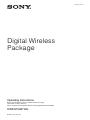
1
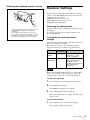
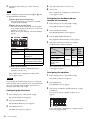
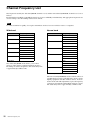
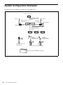
4-460-562-11 (1)
Digital Wireless
Package
Operating Instructions
Before operating the unit, please read this manual thoroughly
and retain it for future reference.
Please read this manual together with the manual supplied with the BC-DWZ1.
DWZ-M70/B70HL
© 2012 Sony Corporation
For the ZTX-M02RC/B02RC
Transmitters
Owner’s Record
The model and serial numbers are located at the rear or on
the bottom of the unit. Record the model and serial
numbers in the space provided below.
Refer to these numbers whenever you call upon your
Sony dealer regarding this product.
Model No. _____________________
Serial No. ______________________
Any change to the antenna or the device could result in the device
exceeding the RF exposure requirements and void user’s authority
to operate this device.
This device complies with FCC radiation exposure limits set forth
for uncontrolled equipment and meets the FCC radio frequency
(RF) Exposure Guidelines in Supplement C to OET65. This device
has very low levels of RF energy that it is deemed to comply
without testing of specific absorption ratio (SAR).
This transmitter must not be co-located or operated in conjunction
with any other antenna or transmitter.
For the customers in Canada
This Class B digital apparatus complies with Canadian ICES-003.
WARNING
Batteries shall not be exposed to excessive heat such as sunshine,
fire or the like.
If the transmitter develops an abnormally high temperature, a
burning odor or smoke during use, remove the battery holder and
stop using the transmitter immediately.
Take care not to burn your fingers when removing the battery
holder as the batteries may be very hot at this time.
For the customers in the U.S.A.
This equipment has been tested and found to comply with the limits
for a Class B digital device, pursuant to Part 15 of the FCC Rules.
These limits are designed to provide reasonable protection against
harmful interference in a residential installation. This equipment
generates, uses, and can radiate radio frequency energy and, if not
installed and used in accordance with the instructions, may cause
harmful interference to radio communications. However, there is
no guarantee that interference will not occur in a particular
installation. If this equipment does cause harmful interference to
radio or television reception, which can be determined by turning
the equipment off and on, the user is encouraged to try to correct the
interference by one or more of the following measures:
– Reorient or relocate the receiving antenna.
– Increase the separation between the equipment and receiver.
– Connect the equipment into an outlet on a circuit different from
that to which the receiver is connected.
– Consult the dealer or an experienced radio/TV technician for
help.
You are cautioned that any changes or modifications not expressly
approved in this manual could void your authority to operate this
equipment.
All interface cables used to connect peripherals must be shielded in
order to comply with the limits for a digital device pursuant to
Subpart B of Part 15 of FCC Rules.
If you have any questions about this product, you may call ;
Sony Customer Information Service Center 1-800-222-7669 or
http://www.sony.com/
This device complies with Industry Canada licence-exempt RSS
standard(s).
Operation is subject to the following two conditions: (1) this device
may not cause interference, and (2) this device must accept any
interference, including interference that may cause undesired
operation of the device.
The term “IC:” before the radio certification number only signifies
that Industry Canada technical specifications were met.
This equipment complies with IC radiation exposure limits set forth
for an uncontrolled environment and meets RSS-102 of the IC radio
frequency (RF) Exposure rules. This equipment has very low levels
of RF energy that are deemed to comply without testing of specific
absorption ratio (SAR).
For the customers in Europe
Hereby, Sony Corporation, declares that this ZTX-M02RC/B02RC
is in compliance with the essential requirements and other relevant
provisions of the Directive 1999/5/EC.
For details, please access the following URL: http://
www.compliance.sony.de/
Voor de klanten in Europa
Hierbij verklaart Sony Corporation dat het toestel ZTX-M02RC/
B02RC in overeenstemming is met de essentiële eisen en de andere
relevante bepalingen van richtlijn 1999/5/EG.
Nadere informatie kunt u vinden op:
http://www.compliance.sony.de/
För kunder i Europa
Härmed intygar Sony Corporation att denna ZTX-M02RC/B02RC
står I överensstämmelse med de väsentliga egenskapskrav och
övriga relevanta bestämmelser som framgår av direktiv 1999/5/EG.
För ytterligare information gå in på följande hemsida: http://
www.compliance.sony.de/
Declaration of Conformity
Trade Name : SONY
Model : ZTX-M02RC/B02RC
Responsible party : Sony Electronics Inc.
Address : 16530 Via Esprillo, San Diego, CA 92127 U.S.A.
Telephone Number : 858-942-2230
Para clientes na Europa
This device complies with part 15 and part 18 of the FCC
Rules. Operation is subject to the following two conditions:
(1) this device may not cause harmful interference, and (2)
this device must accept any interference received,
including interference that may cause undesired operation.
Til europæiske kunder
IMPORTANT NOTE: To comply with the FCC RF exposure
compliance requirements, no change to the antenna or the device is
permitted.
2
This ISM device complies with Canadian ICES-001.
Sony Corporation declara que este ZTX-M02RC/B02RC está
conforme com os requisitos essenciais e outras disposições da
Directiva 1999/5/CE.
Para mais informacoes, por favor consulte a seguinte URL:
http://www.compliance.sony.de/
Undertegnede Sony Corporation erklærer herved, at følgende
udstyr ZTX-M02RC/B02RC overholder de væsentlige krav og
øvrige relevante krav i direktiv 1999/5/EF.
For yderligere information gå ind på følgende hjemmeside:
http://www.compliance.sony.de/
Asiakkaille Euroopassa
Pentru clienţii din Europa
Sony Corporation vakuuttaa täten että ZTX-M02RC/B02RC
tyyppinen laite on direktiivin 1999/5/EY oleellisten vaatimusten ja
sitä koskevien direktiivin muiden ehtojen mukainen.
Halutessasi lisätietoja, käy osoitteessa:
http://www.compliance.sony.de/
Prin prezenta, Sony Corporation declară că acest
ZTX-M02RC/B02RC respectă cerinţele esenţiale și este în
conformitate cu prevederile Directivei 1995/5/EC.
Pentru detalii, vă rugăm accesaţi următoarea adresă:
http://www.compliance.sony.de/
For kunder i Europa
Pre zákazníkov v Európe
Sony Corporation erklærer herved at utstyret ZTX-M02RC/B02RC
er i samsvar med de grunnleggende krav og øvrige relevante krav i
direktiv 1999/5/EF.
For flere detaljer, vennligst se:
http://www.compliance.sony.de/
Sony Corporation týmto vyhlasuje, že ZTX-M02RC/B02RC
spĺňa základné požiadavky a všetky príslušné ustanovenia
Smernice 1999/5/ES.
Podrobnosti získate na nasledovnej webovej adrese:
http://www.compliance.sony.de/
Για τους πελάτες που διαμένουν σε χώρες της
Eυρώπης
Za stranke v Evropi
Με την παρούσα η Sony Corporation δηλώνει τι
ZTX-M02RC/B02RC συμμορφώνεται προς της
ουσιώδεις απαιτήσεις και τις λοιπές σχετικές διατάξεις
της οδηγίας 1999/5/ΕΚ.
Για λεπτομέρειες παρακαλούμε πως ελένξετε την
ακλουθη σελίδα του διαδικτύου:
http://www.compliance.sony.de/
Pro zákazníky v Evropě
Sony Corporation tímto prohlašuje, že tento ZTX-M02RC/
B02RC je ve shodě se základními požadavky a dalšími
příslušnými ustanoveními směrnice 1999/5/ES.
Podrobnosti lze získat na následující URL:
http://www.compliance.sony.de/
Klientidele Euroopas
Sony Corporation kinnitab käesolevaga seadme ZTX-M02RC/
B02RC vastavust 1999/5/EÜ direktiivi põhinõuetele ja nimetatud
direktiivist tulenevatele teistele asjakohastele sätetele.
Üksikasjalikum info: http://www.compliance.sony.de/.
Európai ügyfeleinknek
Alulírott, Sony Corporation nyilatkozom, hogy a(z)
ZTX-M02RC/B02RC megfelel a vonatkozó alapvető
követelményeknek és az 1999/5/EC irányelv egyéb előírásainak.
További információkat a következő weboldalon találhat:
http://www.compliance.sony.de/
Sony Corporation izjavlja, da je ta ZTX-M02RC/B02RC v
skladu z bistvenimi zahtevami in ostalimi relevantnimi določili
direktive 1999/5/ES.
Za podrobnosti vas naprošamo, če pogledate na URL:
http://www.compliance.sony.de/
For the ZRX-HR70 Receivers
Owner’s Record
The model and serial numbers are located at the rear or on
the bottom of the unit. Record the model and serial
numbers in the space provided below.
Refer to these numbers whenever you call upon your
Sony dealer regarding this product.
Model No. _____________________
Serial No. _____________________
IMPORTANT
The nameplate is located on the bottom.
WARNING
Excessive sound pressure from earphones and headphones can
cause hearing loss.
In order to use this product safely, avoid prolonged listening at
excessive sound pressure levels.
Batteries shall not be exposed to excessive heat such as sunshine,
fire or the like.
If the receiver develops an abnormally high temperature, a burning
odor or smoke during use, remove the battery holder and stop using
the receiver immediately.
Take care not to burn your fingers when removing the battery
holder as the batteries may be very hot at this time.
For the customers in the U.S.A.
Dla klientów w Europie
Niniejszym Sony Corporation oświadcza, że ZTX-M02RC/
B02RC jest zgodne z zasadniczymi wymaganiami oraz innymi
stosownymi postanowieniami Dyrektywy 1999/5/WE.
Szczegółowe informacje znaleźć można pod następującym
adresem URL:
http://www.compliance.sony.de/
This equipment has been tested and found to comply with the limits
for a Class B digital device, pursuant to Part 15 of the FCC Rules.
These limits are designed to provide reasonable protection against
harmful interference in a residential installation. This equipment
generates, uses, and can radiate radio frequency energy and, if not
installed and used in accordance with the instructions, may cause
harmful interference to radio communications. However, there is
no guarantee that interference will not occur in a particular
installation. If this equipment does cause harmful interference to
radio or television reception, which can be determined by turning
the equipment off and on, the user is encouraged to try to correct the
interference by one or more of the following measures:
– Reorient or relocate the receiving antenna.
– Increase the separation between the equipment and receiver.
– Connect the equipment into an outlet on a circuit different from
that to which the receiver is connected.
– Consult the dealer or an experienced radio/TV technician for
help.
3
You are cautioned that any changes or modifications not expressly
approved in this manual could void your authority to operate this
equipment.
All interface cables used to connect peripherals must be shielded in
order to comply with the limits for a digital device pursuant to
Subpart B of Part 15 of FCC Rules.
If you have any questions about this product, you may call ;
Sony Customer Information Service Center 1-800-222-7669 or
http://www.sony.com/
Declaration of Conformity
Trade Name : SONY
Model : ZRX-HR70
Responsible party : Sony Electronics Inc.
Address : 16530 Via Esprillo, San Diego, CA 92127 U.S.A.
Telephone Number : 858-942-2230
This device complies with part 15 of the FCC Rules.
Operation is subject to the following two conditions: (1) this
device may not cause harmful interference, and (2) this
device must accept any interference received, including
interference that may cause undesired operation.
For the customers in Canada
This Class B digital apparatus complies with Canadian ICES-003.
For kunder i Europa
Sony Corporation erklærer herved at utstyret ZRX-HR70 er i
samsvar med de grunnleggende krav og øvrige relevante krav i
direktiv 1999/5/EF.
For flere detaljer, vennligst se:
http://www.compliance.sony.de/
Για τους πελάτες που διαμένουν σε χώρες της
Eυρώπης
Με την παρούσα η Sony Corporation δηλώνει τι ZRXHR70 συμμορφώνεται προς της ουσιώδεις απαιτήσεις
και τις λοιπές σχετικές διατάξεις της οδηγίας 1999/5/ΕΚ.
Για λεπτομέρειες παρακαλούμε πως ελένξετε την
ακλουθη σελίδα του διαδικτύου:
http://www.compliance.sony.de/
Pro zákazníky v Evropě
Sony Corporation tímto prohlašuje, že tento ZRX-HR70 je ve
shodě se základními požadavky a dalšími příslušnými
ustanoveními směrnice 1999/5/ES.
Podrobnosti lze získat na následující URL:
http://www.compliance.sony.de/
Klientidele Euroopas
For the customers in Europe
Hereby, Sony Corporation, declares that this ZRX-HR70 is in
compliance with the essential requirements and other relevant
provisions of the Directive 1999/5/EC.
For details, please access the following URL: http://
www.compliance.sony.de/
Voor de klanten in Europa
Hierbij verklaart Sony Corporation dat het toestel ZRX-HR70 in
overeenstemming is met de essentiële eisen en de andere relevante
bepalingen van richtlijn 1999/5/EG.
Nadere informatie kunt u vinden op:
http://www.compliance.sony.de/
Sony Corporation kinnitab käesolevaga seadme ZRX-HR70
vastavust 1999/5/EÜ direktiivi põhinõuetele ja nimetatud
direktiivist tulenevatele teistele asjakohastele sätetele.
Üksikasjalikum info: http://www.compliance.sony.de/.
Európai ügyfeleinknek
Alulírott, Sony Corporation nyilatkozom, hogy a(z) ZRXHR70 megfelel a vonatkozó alapvető követelményeknek és az
1999/5/EC irányelv egyéb előírásainak.
További információkat a következő weboldalon találhat:
http://www.compliance.sony.de/
För kunder i Europa
Härmed intygar Sony Corporation att denna ZRX-HR70 står I
överensstämmelse med de väsentliga egenskapskrav och övriga
relevanta bestämmelser som framgår av direktiv 1999/5/EG.
För ytterligare information gå in på följande hemsida: http://
www.compliance.sony.de/
Para clientes na Europa
Sony Corporation declara que este ZRX-HR70 está conforme com
os requisitos essenciais e outras disposições da Directiva 1999/5/
CE.
Para mais informacoes, por favor consulte a seguinte URL:
http://www.compliance.sony.de/
Til europæiske kunder
Undertegnede Sony Corporation erklærer herved, at følgende
udstyr ZRX-HR70 overholder de væsentlige krav og øvrige
relevante krav i direktiv 1999/5/EF.
For yderligere information gå ind på følgende hjemmeside:
http://www.compliance.sony.de/
Asiakkaille Euroopassa
Sony Corporation vakuuttaa täten että ZRX-HR70 tyyppinen laite
on direktiivin 1999/5/EY oleellisten vaatimusten ja sitä koskevien
direktiivin muiden ehtojen mukainen.
Halutessasi lisätietoja, käy osoitteessa:
http://www.compliance.sony.de/
4
Dla klientów w Europie
Niniejszym Sony Corporation oświadcza, że ZRX-HR70 jest
zgodne z zasadniczymi wymaganiami oraz innymi stosownymi
postanowieniami Dyrektywy 1999/5/WE.
Szczegółowe informacje znaleźć można pod następującym
adresem URL:
http://www.compliance.sony.de/
Pentru clienţii din Europa
Prin prezenta, Sony Corporation declară că acest ZRX-HR70
respectă cerinţele esenţiale și este în conformitate cu
prevederile Directivei 1995/5/EC.
Pentru detalii, vă rugăm accesaţi următoarea adresă:
http://www.compliance.sony.de/
Pre zákazníkov v Európe
CAUTION
Sony Corporation týmto vyhlasuje, že ZRX-HR70 spĺňa
základné požiadavky a všetky príslušné ustanovenia Smernice
1999/5/ES.
Podrobnosti získate na nasledovnej webovej adrese:
http://www.compliance.sony.de/
The apparatus shall not be exposed to dripping or splashing. No
objects filled with liquids, such as vases, shall be placed on the
apparatus.
Za stranke v Evropi
The unit is not disconnected from the AC power source (mains) as
long as it is connected to the wall outlet, even if the unit itself has
been turned off.
Sony Corporation izjavlja, da je ta ZRX-HR70 v skladu z
bistvenimi zahtevami in ostalimi relevantnimi določili
direktive 1999/5/ES.
Za podrobnosti vas naprošamo, če pogledate na URL:
http://www.compliance.sony.de/
For the ECM-LZ1UBMP/
HZ1UBMP Microphones
About the supplied AC adapter
For the customers in Europe
Important Safety Instructions
•
•
•
•
•
•
•
•
•
•
•
•
Read these instructions.
Keep these instructions.
Heed all warnings.
Follow all instructions.
Do not use this apparatus near water.
Clean only with dry cloth.
Do not block any ventilation openings.
Install in accordance with the manufacturer’s instructions.
Do not install near any heat sources such as radiators, heat
registers, stoves, or other apparatus (including amplifiers) that
produce heat.
Do not defeat the safety purpose of the polarized or groundingtype plug. A polarized plug has two blades with one wider than
the other. A grounding-type plug has two blades and a third
grounding prong. The wide blade or the third prong are provided
for your safety. If the provided plug does not fit into your outlet,
consult an electrician for replacement of the obsolete outlet.
Protect the power cord from being walked on or pinched
particularly at plugs, convenience receptacles, and the point
where they exit from the apparatus.
Only use attachments/accessories specified by the manufacturer.
Use only with the cart, stand, tripod, bracket, or table specified
by the manufacturer, or sold with the apparatus. When a cart is
used, use caution when moving the cart/apparatus combination to
avoid injury from tip-over.
This product with the CE marking complies with the EMC
Directive issued by the Commission of the European Community.
Compliance with this directive implies conformity to the following
European standards:
• EN55103-1 : Electromagnetic Interference(Emission)
• EN55103-2 : Electromagnetic Susceptibility(Immunity)
This product is intended for use in the following Electromagnetic
Environments: E1 (residential), E2 (commercial and light
industrial), E3 (urban outdoors), E4 (controlled EMC
environment, ex. TV studio).
This product has been manufactured by or on behalf of Sony
Corporation, 1-7-1 Konan Minato-ku Tokyo, 108-0075 Japan.
Inquiries related to product compliance based on European Union
legislation shall be addressed to the authorized representative, Sony
Deutschland GmbH, Hedelfinger Strasse 61, 70327 Stuttgart,
Germany. For any service or guarantee matters, please refer to the
addresses provided in the separate service or guarantee documents.
• Unplug this apparatus during lightning storms or when unused
for long periods of time.
• Refer all servicing to qualified service personnel. Servicing is
required when the apparatus has been damaged in any way, such
as power-supply cord or plug is damaged, liquid has been spilled
or objects have fallen into the apparatus, the apparatus has been
exposed to rain or moisture, does not operate normally, or has
been dropped.
WARNING
To reduce the risk of fire or electric shock, do not
expose this apparatus to rain or moisture.
To avoid electrical shock, do not open the cabinet.
Refer servicing to qualified personnel only.
When installing the unit, incorporate a readily accessible
disconnect device in the fixed wiring, or connect the power plug to
an easily accessible socket-outlet near the unit. If a fault should
occur during operation of the unit, operate the disconnect device to
switch the power supply off, or disconnect the power plug.
5
Table of Contents
Package Contents .......................................7
DWZ-M70 .................................................... 7
DWZ-B70HL................................................ 7
Features .......................................................8
DWZ-M70 .................................................... 8
DWZ-B70HL................................................ 8
ZTX-M02RC ................................................ 8
ZTX-B02RC ................................................. 8
ZRX-HR70 ................................................... 8
Parts Identification ......................................9
DWZ-M70 .................................................... 9
DWZ-B70HL.............................................. 11
Power Supply.............................................12
Inserting Batteries....................................... 12
Attaching the Supplied Accessories .......13
Attaching the Supplied Accessories to the
Handheld Microphone
(ZTX-M02RC) .................................. 13
Attaching the Supplied Accessories to the
Half-Rack Receiver (ZRX-HR70) .... 14
Attaching the Supplied Accessories to the
Body-Pack Transmitter
(ZTX-B02RC) ................................... 14
Using the Headset Microphone
(ECM-HZ1UBMP) ........................... 14
Receiver Settings ......................................15
Transmitter Settings .................................17
Configuring the Transmitting Channel
Settings .............................................. 17
Channel Display.......................................... 18
Enabling Encrypted Transmission ..........18
Channel Frequency List............................20
System Configuration Examples .............22
Troubleshooting ........................................23
Important Notes on Use............................25
Usage and Storage ...................................... 25
Cleaning...................................................... 25
Notes on Charging Batteries....................25
Specifications ............................................26
DWZ-M70 .................................................. 26
DWZ-B70HL.............................................. 27
6
Table of Contents
Package Contents
This manual contains information on the Sony DWZ-M70/B70HL Digital Wireless Packages. The contents of each
package are as follows.
DWZ-M70
This set includes a handheld microphone (transmitter: ZTX-M02RC) and a half-rack receiver (receiver: ZRX-HR70).
ZTX-M02RC handheld
microphone (1)
ZRX-HR70 half-rack
receiver (1)
Supplied accessories
Mic holder (1)
Antenna (2)
AC adapter (1)
Power cord (1)
(for KR4 model only)
Power cord (2)
(for E model only)
Conversion adapter (1)
(for E model only)
Before Use (1)
Operating Instructions
(CD-ROM) (1)
Warranty card (1)
(for UC model only)
Warranty booklet (1)
(for SYV model only)
DWZ-B70HL
This set includes a body-pack (transmitter: ZTX-B02RC) and a half-rack receiver (receiver: ZRX-HR70).
ZTX-B02RC body-pack
transmitter (1)
Belt clip (1)
• Belt clip screw (1)
ZRX-HR70 half-rack
receiver (1)
Antenna (2)
Supplied accessories
ECM-LZ1UBMP uni-directional
lavalier microphone (1)
• Wind screen (1)
• Mic holder clip (1)
ECM-HZ1UBMP headset
microphone (1)
• Wind screen (1)
• Cord clip (1)
• Headband (1)
AC adapter (1)
Power cord (1) (for KR4 model only)
Power cord (2) (for E model only)
Conversion adapter (1) (for E model only)
Before Use (1)
Operating Instructions (CD-ROM) (1)
Warranty card (1) (for UC model only)
Warranty booklet (1) (for SYV model only)
Package Contents
7
Features
The DWZ series is a digital wireless system that
combines Sony’s consistently developed superior audio
technology, highly reliable wireless technology, and
state-of-the-art digital signal processing technology.
Using an unlicensed 2.4 GHz band, the system provides
wide-range functionality with simple, user-friendly
operability.
By providing a package that is optimized for specific
usage environments, the system offers a wireless solution
to users ranging from those inexperienced with wireless
systems to seasoned professionals.
Superb audio quality
By transmitting audio signals via 24-bit high-quality
linear PCM digital transmission, without signal
compression, decompression, or similar processing, the
system provides superb audio quality and high-bandwidth
transmissions that approach that of wired microphones.
High reliability
By allowing you to select from two RF modes based on
your intended use and incorporating Sony’s unique data
processing technology, the system provides highlyreliable wireless transmission in wireless LAN
environments. In addition, the two RF modes each consist
of six channels, allowing you to select the appropriate RF
mode and channel according to your intended purpose.
The receiver is equipped with two antennas with the
antenna with the best reception status selected
automatically via space diversity, providing stable
reception with minimized audio breakup and noise
occurrences.
Highly confidential transmissions are also possible using
the 128-bit AES (Advanced Encryption Standard).
DWZ-M70
This package includes a rechargeable handheld
microphone (transmitter: ZTX-M02RC) and a half-rack
receiver (receiver: ZRX-HR70) and is ideal for use during
speeches and vocal performances.
DWZ-B70HL
This package can connect to headset microphones and
lavalier microphones, and includes a rechargeable bodypack microphone (transmitter: ZTX-B02RC) and a halfrack receiver (receiver: ZRX-HR70).
ZTX-M02RC
A microphone designed with a sturdy metal body.
Using an optional battery charger (BC-DWZ1) and
nickel-metal-hydride rechargeable batteries makes
contactless recharging possible. The unit is equipped with
a sliding power switch for easy ON/OFF switching and an
8
Features
attenuator adjustment function for a wide range of audio
input level support. In addition, the interchangeable
microphone unit allows you to use the microphone in a
variety of applications.
* The microphone unit’s mounting area has a diameter of 31.3 mm
and a pitch of 1.0 mm.
ZTX-B02RC
A transmitter designed with a sturdy metal body.
Using an optional battery charger (BC-DWZ1) and
nickel-metal-hydride rechargeable batteries makes
contactless recharging possible. Equipped with a muting
function, an instrument or line input / mic input switching
function, and an attenuator adjustment function, the unit
supports a wide range of audio input levels. The supplied
belt clip can be rotated in 90-degree increments, allowing
you to adjust the direction in which the cables extend
based on your environment.
ZRX-HR70
A half-rack receiver equipped with large-screen highresolution color LCD that combines high-functionality
with simple operability.
The unit’s high-performance DSP and real-time
intelligent feedback reduction function suppresses
distracting howling noise.
The Best Channel Selection and Clear Channel Scan
functions allow quick and easy configuration of safe
channels. In addition, the 5-band graphic equalizer allows
wide-range audio-quality adjustment. You can also select
whether the muting function applies to the
UNBALANCED/BALANCED OUTPUT connector*.
Using the optional RMM-HRD1 Rack Mount Kit allows
you to mount the unit on a rack.
* The muting function is not available on the ZTX-M02RC.
Note
Some functions may not be available depending on the
combination of devices used.
Parts Identification
e Antenna cover
Contains the antenna.
Caution
Do not squeeze the antenna cover. Doing so will weaken
the signal that is transmitted, decreasing the transmission
range.
DWZ-M70
Handheld microphone (transmitter: ZTXM02RC)
Top (when microphone unit is removed)
f ATT (attenuator) switch
Set the attenuation level based on the sound volume.
Attenuation level (dB) When to use
0
Standard switch position
6
Set to this position if a red bar
occasionally appears in the audio
level meter of the receiver.
12
Set to this position if a red bar
always appears in the audio level
meter of the receiver.
Grip interior
The attenuator switch is located at the top of the unit when
the microphone unit is removed.
For details on attaching and removing the microphone
unit, see “Replacing the microphone unit” (page 13).
a Microphone unit
The standard-equipped microphone unit can be
interchanged with another interchangeable microphone
unit with a diameter of 31.3 mm and a pitch of 1.0 mm.
For details on attaching and removing the microphone
unit, see “Replacing the microphone unit” (page 13).
b BATT/CHARGE (remaining battery / charge)
indicator
Lights when the unit is turned on. This indicates the
remaining battery charge or the charge status.
Indicator
Status
Lit (green)
Good
Lit (red)
Almost dead
Lit (orange)
Charging
The remaining battery indication only appears when
alkaline dry cell batteries are being used.
c POWER switch
Turns the unit on or off.
g Channel display
Displays the transmission channel.
The display disappears after about 10 seconds. You can
display it again by pressing the channel selection button.
For details on the channel display, see “Channel
Display” (page 18).
h Channel selection button
Allows you to select the RF mode and the transmitting
channel.
For details on selecting the RF mode and transmitting
channel, see “Configuring the Transmitting Channel
Settings” (page 17).
i ENCRYPTION switch
Allows you to use the encrypted transmission function.
For details on the encrypted transmission function, see
“Enabling Encrypted Transmission” (page 18).
Half-rack receiver (receiver: ZRX-HR70)
Front
d Grip
Contains the control buttons, channel display, and battery
compartment.
Open the grip to configure channel settings and replace
the batteries.
For details on opening the grip, see “Inserting Batteries”
(page 12).
a POWER button
Turns the unit on or off.
Parts Identification
9
b POWER indicator
Lights when the unit is turned on.
Rear
c Display
a ANTENNA a/b connector (BNC type)
Connect the supplied antenna here.
Displays setting configurations and other information.
A Receiving channel indicator
Displays the receiving channel.
B Encryption status display
Displays whether encrypted transmission is enabled.
C Remaining transmitter battery indicator
Displays the remaining battery charge of the transmitter.
An approximate duration is displayed for the remaining
usage time. This duration appears only when signals are
being received.
D Audio level meter
Displays the audio level.
Set the audio level so that the red bar is not displayed
continuously.
E FBR (feedback reducer) status indicator
Displays the status of the feedback reducer in one of four
levels (Off, Low, Mid, High).
F EQ (equalizer) status indicator
Displays the on/off status of the equalizer.
G Receiving level indicator
Displays the reception status of the radio signal.
More bars indicate more stable reception.
d ESC (escape) button
Cancels operations, or returns to the main screen from the
settings screen.
e Rotary encoder
Allows you to change settings.
For details on changing settings, see “Receiver Settings”
(page 15).
b UNBALANCED OUTPUT AUX/TUNER
(external audio output) connector (headphone
jack)
Connect monitoring equipment and similar peripheral
devices here.
You can configure muting based on your intended use.
For details on settings, see “Configuring the transmitter
muting function for the output connectors” (page 17).
For details on connections, see “System Configuration
Examples” (page 22).
c UNBALANCED OUTPUT MAIN (main audio
output) connector (headphone jack)
Connect a mixer or an amp here.
You can configure muting based on your intended use.
For details on settings, see “Configuring the transmitter
muting function for the output connectors” (page 17).
For details on connections, see “System Configuration
Examples” (page 22).
d BALANCED OUTPUT connector (XLR type)
Connect a mixer or similar device here.
You can configure muting based on your intended use.
For details on settings, see “Configuring the transmitter
muting function for the output connectors” (page 17).
For details on connections, see “System Configuration
Examples” (page 22).
e MIC/LINE (audio output level) selector
Selects the audio output level of the BALANCED
OUTPUT connector.
MIC: Sets the audio output level to the mic level.
LINE: Sets the audio output level to the line level.
Caution
Do not set the selector to the LINE position while
outputting audio to an audio mixer or similar device.
Inputting audio at excessive levels may distort audio or
damage the playback/recording device.
10
Parts Identification
f Cable clamp
Secures the cable of the supplied AC adapter.
g DC IN 12V (power input) connector
Connect the supplied AC adapter here.
DWZ-B70HL
Body-pack transmitter (transmitter: ZTXB02RC)
e AUDIO/MUTING indicator
Indicates the input level of the audio signal and the status
of the muting function.
Indicator
Status
Lit (green)
Audio input present
Lit (red)
Excessive audio input
Off
Audio input weak or nonexistent
Blinking
(orange)
Muting function enabled (i.e., audio
disabled)
f INPUT switch
Set this based on the connected equipment.
MIC: Set to this position when a microphone is
connected.
INST/LINE: Set to this position when a guitar or audio
equipment is connected.
Caution
Do not set the switch to the MIC position while inputting
audio from an audio mixer or similar device. Outputting
audio at excessive levels may distort audio or damage the
playback/recording device.
For details on the setting, see “System Configuration
Examples” (page 22).
g ATT (attenuator) switch
Set the attenuation level based on the connected
equipment.
a Antenna cover
Contains the antenna.
Caution
Do not squeeze the antenna cover. Doing so will weaken
the signal that is transmitted, decreasing the transmission
range.
b BATT/CHARGE (remaining battery / charge)
indicator
Lights when the unit is turned on. This indicates the
remaining battery charge or the charge status.
Indicator
Status
Lit (green)
Good
Lit (red)
Almost dead
Lit (orange)
Charging
The remaining battery indication only appears when
alkaline dry cell batteries are being used.
c ENCRYPTION switch
Allows you to use the encrypted transmission function.
For details on the encrypted transmission function, see
“Enabling Encrypted Transmission” (page 18).
d Audio input connector
Connect the supplied microphone or use a guitar cable
(GC-0.7BMP; not supplied) to connect a guitar or similar
instrument here.
Attenuation level (dB)
When to use
0
Standard switch position
10
Set to this position if the AUDIO/
MUTING indicator on the receiver
occasionally lights red.
20
Set to this position if the AUDIO/
MUTING indicator on the receiver
is always lit red.
h Battery compartment
Insert two LR6 (size AA) batteries here.
For details on how to insert batteries, see “Inserting
Batteries” (page 12).
i POWER/MUTING button
Turns the unit on or off. This button can also be used to
enable or disable the muting function.
Function
Button operation
Turn power on
Press the button for at least 1
second
Turn power off
Press the button until indicator
turns off
Enable muting function
Press the button
Disable muting function
j Channel display
Displays the transmission channel.
Parts Identification
11
The display disappears after about 10 seconds. You can
display it again by pressing the channel selection button.
For details on the channel display, see “Channel
Display” (page 18).
k CHANNEL SELECT button
Allows you to select the RF mode and the transmitting
channel.
For details on selecting the RF mode and transmitting
channel, see “Configuring the Transmitting Channel
Settings” (page 17).
Half-rack receiver (receiver: ZRX-HR70)
For details on the half-rack receiver, see “ZRX-HR70
half-rack receiver” (page 27) for the DWZ-M70.
Power Supply
This section describes the power supply for each device.
For details on how to insert batteries, see “Inserting
Batteries” (page 12).
Handheld microphone (ZTX-M02RC),
body-pack transmitter (ZTX-B02RC)
Power supplied by two LR6 (size AA) batteries.
The following types of battery can be used.
• Alkaline dry cell batteries
• Rechargeable nickel-metal hydride batteries
• Lithium batteries
Half-rack receiver (ZRX-HR70)
Power supplied by the supplied AC adapter.
Inserting Batteries
CAUTION
Danger of explosion if battery is incorrectly replaced.
Replace only with the same or equivalent type
recommended by the manufacturer.
When you dispose of the battery, you must obey the law
in the relative area or country.
Notes
• Always use sets of the same type of battery. Do not use
batteries of different types or remaining charges
together as a set.
• Replacing the batteries during operation will result in
high noise. Be sure to turn off the unit before replacing
the batteries.
Handheld microphone (ZTX-M02RC)
12
Power Supply
1
Slide the POWER switch to turn off the unit.
2
Turn the grip in the direction of the arrow, and pull
down the grip until the battery compartment is shown.
3
Insert two new LR6 (size AA) batteries while making
sure the polarities are correct.
Attaching the Supplied
Accessories
This section describes how to attach the supplied
accessories to each unit.
4
Close the grip and turn it in the reverse direction in
the step 2 above.
Body-pack transmitter (ZTX-B02RC)
1
Press and hold the POWER/MUTING button to turn
off the unit.
2
Slide the battery-compartment catches inward (in the
direction of the arrows b B) to take out the
compartment.
3
Insert two new LR6 (size AA) batteries into the
battery compartment while making sure the polarities
are correct, and then reinsert the compartment into the
unit.
Attaching the Supplied Accessories
to the Handheld Microphone (ZTXM02RC)
Attaching the microphone holder
Insert the bottom part of the
microphone into the holder.
Replacing the microphone unit
To remove the microphone unit
Turn the microphone unit in the direction of the arrow.
To attach the microphone unit
Turn the microphone unit in the opposite direction from
when you removed it, and make sure that the unit is
securely attached to the microphone.
Attaching the Supplied Accessories
13
Attaching the Supplied Accessories
to the Half-Rack Receiver (ZRXHR70)
To attach to a belt
Attaching the antenna
Insert the supplied antenna into the
ANTENNA a/b connector at the rear of
the receiver and turn it.
Slide the belt into the belt clip on the unit
completely, and make sure it is secure.
Caution
Depending on the thickness and width of the strap, the
belt clip may not attach securely.
Using the Headset Microphone
(ECM-HZ1UBMP)
To remove the feet
Wearing the microphone
Use a flat-bladed screwdriver or
similar tool to remove the pins that
secure the feet, and then remove the
feet from the half-rack receiver.
Attaching the Supplied Accessories
to the Body-Pack Transmitter (ZTXB02RC)
Attaching the belt clip
Align the mounting hole at the rear of the transmitter with the
hole in the middle of the supplied belt clip, and secure the belt
clip using the supplied belt clip screw.
You can also rotate the belt clip 180 degrees or 90 degrees to
the left or right before securing it.
14
Attaching the Supplied Accessories
The ECM-HZ1UBMP is designed to be worn on either ear.
Press the ear clip in the direction of the arrows to fit the shape
of the ear.
To improve sound collection, adjust the sound collector (1) of
the microphone unit so that is faces the mouth by using the
guideline (protrusion (2)) as a guide.
Attaching the headband and the cord clip
Receiver Settings
Use the rotary encoder and the ESC button to configure
settings on the ZRX-HR70 half-rack receiver. Perform
setting operations as follows.
Confirm: Press the rotary encoder.
Move cursor: Turn the rotary encoder.
Cancel: Press the ESC button.
Displaying the settings menu
To wear the microphone more securely, attach the
supplied headband (1) before wearing the
microphone.
The headband can be attached on either side.
To prevent the microphone from falling off, attach
the supplied cord clip (2) to the microphone cable,
then clip the microphone cable to the clothing.
Press the rotary encoder to display the [Setup] screen in
the display.
To return to the main screen from the [Setup] screen,
press the ESC button.
Configuring the receiving channel
settings
Two RF modes (channel modes), wide band and narrow
band, are available on the DWZ.
Each RF mode consists of six channels. Select the
appropriate channel according to your intended use.
RF mode
Transmitting
Description
channel number
Wide band
(WIDE)
1/2/3/4/5/6
Narrow band a/b/c/d/e/f
(NARROW)
This mode reduces any
interference to other
wireless equipment.
This mode uses the Clear
Channel Scan function,
making it useful for
avoiding any interference
from other wireless
equipment.
Caution
When using multiple channels (up to six), the two RF
modes, wide band and narrow band, cannot be used
simultaneously. Select only one RF mode during use.
To select the RF mode
1
In the [Setup] screen, select [Advanced Settings].
2
Select [RF Mode Settings].
The [RF Mode Settings] screen appears.
3
Select [Wide Band] or [Narrow Band].
When the configuration is complete, the main screen
appears again.
To select the channel
1
In the [Setup] screen, select [Channel Setup].
The [Channel Setup] screen appears.
Receiver Settings
15
2
Specify the channel using one of the following
methods.
4
Select the effect level you want to use.
5
Select [Set].
Note
This completes the configuration, and the main
screen appears again.
When configuring settings using method A or B, turn
off all transmitters beforehand.
ASelect [Best Channel Selection]
The channel with the least interference will be
configured automatically.
BSelect [Clear Channel Scan]
The status of all the channels in the selected RF
mode will be displayed, allowing you to select the
channel you want to use.
If there are no open channels, “No Clear Channel”
appears.
Configuring the feedback reducer
function for connectors
1
In the [Setup] screen, select [Audio Setup].
The [Audio Setup] screen appears.
2
Select [Feedback Reducer].
The [Feedback Reducer] screen appears.
3
Select [Apply Feedback Reducer].
The [Apply Feedback Reducer] screen appears.
4
Display
Status
White font
(underlined)
Channel with low interference.
White font
Channel with relatively low
interference.
Gray font
Select the connectors for which you want the
feedback reducer function enabled.
Screen display
Connector
To
To All
To
Outputs Balanced AUX/
& Main
Tuner
Only
Only
–
BALANCED OUTPUT
UNBALANCED
OUTPUT MAIN
Channel with high
interference, or channel that is
being used by another device.
Enabled
UNBALANCED
OUTPUT AUX/
TUNER
“No Clear Channel” No usable channels available.
–
Enabled
–
Enabled
This completes the configuration, and the main
screen appears again.
CSelect [Manual Setup]
Configure the channel manually. Select the
channel you want to use.
Configuring the equalizer
This completes the configuration, and the main
screen appears again.
1
The [Audio Setup] screen appears.
Caution
If you change the channel setting, be sure to change the
channel setting on the transmitter to the same channel. If
the receiver channel and transmitter channel are not
identical, audio will not be output.
Configuring the effect level
1
In the [Setup] screen, select [Audio Setup].
In the [Setup] screen, select [Audio Setup].
2
Select [Equalizer].
The [Equalizer] screen appears.
3
Select [On] to enable the equalizer function, or [Off]
to disable it.
If you select [On], the equalizer settings screen
appears.
The [Audio Setup] screen appears.
2
Select [Feedback Reducer].
The [Feedback Reducer] screen appears.
3
Select [Effect Level].
The [Effect Level] screen appears.
16
Receiver Settings
If you select [Off], configuration is complete and the
main screen appears again.
4
5
Select the frequency for which you want to adjust the
level, and adjust the setting.
Select [Set].
The setting value is saved.
To cancel the setting, press the ESC button.
Configuring the Transmitting
Channel Settings
Configuring the transmitter muting
function for the output connectors
You can select whether to enable the muting function
controlled by the transmitter for the audio output of each
output connector.
1
In the [Setup] screen, select [Audio Setup].
The [Audio Setup] screen appears.
2
Transmitter Settings
Two RF modes (channel modes), wide band and narrow
band, are available on the DWZ.
Each RF mode consists of six channels. Select the
appropriate channel according to your intended use.
RF mode
Transmitting
Description
channel number
Wide band
(WIDE)
1/2/3/4/5/6
Narrow band a/b/c/d/e/f
(NARROW)
Select [TX Muting].
The [Apply TX Muting] screen appears.
3
Select the connectors for which you want the muting
function enabled.
Screen display
Connector
To
To All
To
Outputs Balanced AUX/
& Main
Tuner
Only
Only
This mode uses the Clear
Channel Scan function,
making it useful for
avoiding any interference
from other wireless
equipment.
Caution
The two RF modes, wide band and narrow band, cannot
be used simultaneously. Select only one RF mode during
use.
–
BALANCED OUTPUT
UNBALANCED
OUTPUT MAIN
This mode reduces any
interference to other
wireless equipment.
Enabled
–
Enabled
UNBALANCED
OUTPUT AUX/
TUNER
Selecting the RF mode
1
–
Enabled
To turn off the ZTX-M02RC, slide the POWER
switch to the OFF position.
To turn off the ZTX-B02RC, press and hold the
POWER/MUTING button.
This completes the configuration, and the main
screen appears again.
Configuring the battery type
2
Specify the type of battery that is being used in the
transmitter so that the transmitter’s remaining battery
charge can be displayed properly on this unit.
1
In the [Setup] screen, select [Advanced Settings].
2
Select [Battery Type].
3
Select the battery type.
Turn off the unit.
For the ZTX-M02RC, slide the POWER switch to the
ON position while holding down the channel
selection button.
For the ZTX-B02RC, press and hold the POWER/
MUTING button (about 1 second) while holding
down the channel selection button.
“0” blinks in the channel display.
Alkaline: Alkaline dry cell batteries are being used in
the transmitter.
Ni-MH: Rechargeable nickel-metal hydride batteries
are being used in the transmitter.
Lithium: Lithium batteries are being used in the
transmitter.
This completes the configuration, and the main
screen appears again.
3
Press the channel selection button to select “1” or “a.”
4
Press and hold the channel selection button.
Selecting the channel
1
Press and hold the channel selection button while the
unit is turned on.
The channel display blinks.
2
Press the channel selection button to select the
channel.
Transmitter Settings
17
3
Press and hold the channel selection button to apply
the channel selection.
Caution
If you change the channel setting on the transmitter, be
sure to change the channel setting on the receiver to the
same channel. If the receiver channel and transmitter
channel are not identical, audio will not be output.
Enabling Encrypted
Transmission
Encrypted transmission will only be enabled on
transmitter and receiver pairs for which the following
settings have been configured.
Notes
Channel Display
Each channel will appear as follows in the transmitter’s
channel display.
RF mode
Channel number
Wide band (WIDE)
1
2
3
4
5
6
• After encrypted transmission is enabled, the enabled
settings will remain until they are disabled.
• To disable encrypted transmission, disable the settings
on both the transmitter and the receiver.
• If you want to change the transmitter and receiver pair
for which encrypted transmission is used, you must
configure the settings again.
Enabling encrypted transmission
1
Narrow band (NARROW) a
b
c
d
e
f
Synchronize the transmitter and receiver channels.
For details on configuring the transmitter’s channel
and the receiver’s channel, see “Configuring the
Transmitting Channel Settings” (page 17) and
“Configuring the receiving channel settings”
(page 15) respectively.
2
Set the ENCRYPTION switch on the transmitter to
the OFF position.
Leave the power on.
3
In the [Setup] screen of the receiver, select
[Advanced Settings].
The [Advanced Settings] screen appears.
For details on displaying the [Setup] screen, see
“Displaying the settings menu” (page 15).
4
Select [Encryption].
The [Encryption] screen appears.
5
Set the [Encryption] setting to [On].
6
Set the ENCRYPTION switch on the transmitter to
the ON position.
When the setting is properly enabled, “Complete”
appears on the receiver.
Note
If “Connection Failed” appears on the receiver, the setting
has not been configured properly. Configure the settings
again from step 1.
18
Enabling Encrypted Transmission
Disabling encrypted transmission
1
Set the ENCRYPTION switch on the transmitter to
the OFF position.
2
In the [Setup] screen of the receiver, select
[Advanced Settings].
The [Advanced Settings] screen appears.
For details on displaying the [Setup] screen, see
“Displaying the settings menu” (page 15).
3
Select [Encryption].
The [Encryption] screen appears.
4
Set the [Encryption] setting to [Off].
Encrypted transmission status display on
the receiver
Icon
display
Encrypted
transmission
status
Description
Lit
Encrypted
transmission in
progress.
Encrypted transmission
is enabled.
Blinking
Encrypted
transmission not
configured properly.
The encrypted
transmission settings on
the transmitter and
receiver do not match.
Off
Normal transmission
The encrypted
in progress or there is transmission setting is
no signal reception.
set to OFF and normal
transmission is enabled,
or there is no RF signal.
Enabling Encrypted Transmission
19
Channel Frequency List
The frequencies used by the wide band (WIDE, channels 1 to 6) and the narrow band (NARROW, channels a to f) are as
follows.
Each channel uses multiple compatible frequencies to increase reliability and redundancy. The appropriate frequencies are
used according to the surrounding wireless environment.
Note
To ensure transmission quality, do not place transmitters and receivers near wireless routers or computers.
Wide band
Narrow band
Channel number
Frequency
Channel number
Frequency
1
2402
a
2469.5
2478.5
2
2474
2421.5
2472.5
3
4
2447
2475.5
2451.5
c
2415.5
2446.5
2420
2449.5
2424.5
2469.5
6
2442.5
2427.5
2424.5
5
2478.5
b
d
2456
2405
2460.5
2452.5
2465
(Unit: MHz)
The wide band (WIDE) mode allows you to reduce
effects to other wireless equipment without extensive
knowledge of wireless frequencies. The audio delay time
is approximately 6 milliseconds.
e
2429
2433.5
2438
f
2402
2406.5
2411
(Unit: MHz)
The narrow band (NARROW) mode avoids the effects of
2.4 GHz wireless remote controls that are used to operate
lighting equipment and other wireless devices. You can
use this mode and make adjustments to prevent frequency
overlaps in environments with multiple wireless systems.
The audio delay time is approximately 3 milliseconds.
20
Channel Frequency List
Wi-Fi channels
The frequencies covered by each Wi-Fi channel are as follows. The ranges that cover the most commonly used channels,
channels 1, 6, and 11, are shown in grey.
Wi-Fi channels
1
Frequencies (MHz)
DWZ
Wide band
DWZ
Narrow band
2
3
4
5
6
7
8
9
10
11
12
13
2402 2407 2412 2417 2422 2427 2432 2437 2442 2447 2452 2457 2462 2467 2472 2477 2482
Ch 1
Ch 2
Ch 3
Ch 4
Ch 5
Ch 6
Ch a
Ch b
Ch c
Ch d
Ch e
Ch f
Channel Frequency List
21
System Configuration Examples
The following system configuration examples are of the DWZ series.
Mixer, recorder, etc.
Antenna
Half-rack receiver
(ZRX-HR70)
UNBALANCED OUTPUT
MAIN (main audio output)
connector
Antenna
ANTENNA
a connector
AC adapter
ANTENNA b connector
DC IN 12V (power input) connector
BALANCED OUTPUT
connector
Mixer
Power amp
Headset
microphone
(ECM-HZ1UBMP)
Speaker
Lavalier
microphone
(ECM-LZ1UBMP)
Handheld microphone
(ZTX-M02RC)
Body-pack transmitter (ZTX-M02RC)
Battery charger (BC-DWZ1) (not supplied)
22
System Configuration Examples
Troubleshooting
Check the following if problems occur.
Should any problem persist, consult your Sony dealer.
Symptom
Meanings
Remedy
The unit does not turn on. The polarity orientation of the batteries in the Insert the batteries with the correct polarity
battery compartment is incorrect.
orientation.
The batteries drain
quickly.
The batteries are exhausted.
Replace the batteries with new ones.
The batteries are exhausted.
Replace the batteries with new ones.
Manganese batteries are being used.
Use alkaline batteries. The battery life of a manganese
battery is less than half that of an alkaline battery.
The unit is being used under cold conditions. The batteries drain quickly under cold conditions.
There is no sound.
The sound is weak.
The RF mode or channel setting on the
transmitter is different from that on the
receiver.
Use the same RF mode and channel setting on both
the transmitter and the receiver.
The muting function is enabled.
Disable the muting function.
The transmitter has been placed on the
battery charger and is recharging.
Remove the transmitter from the battery charger.
The encrypted transmission settings on the
transmitter and receiver do not match.
Configure the encrypted transmission settings on
the transmitter and receiver again.
The attenuation level on the transmitter is too The input level is low. Set the attenuation level on
high.
the transmitter to the appropriate level.
The output level of the receiver does not
Set the MIC/LINE selector according to the input
match the input level setting of the connected level of the connected device. (ZRX-HR70)
device.
The sound is distorted.
The attenuation level of the transmitter is too The audio input level is too high. Set the attenuation level
on the transmitter to a level where sound is not distorted.
low.
The transmitter’s MIC/LINE selector is set to
MIC.
The audio input level is too high. Specify INST/LINE
input.
The output level of the receiver does not
Set the MIC/LINE selector according to the input
match the input level setting of the connected level of the connected device. (ZRX-HR70)
device.
Noise occurs.
The transmitter and receiver are far away
from each other.
Shorten the distance between the transmitter and
receiver until audio breakup does not occur.
Signal interference from other devices is
occurring.
Change the selected channel, or move the devices
that are causing interference away from the unit.
Two or more transmitters are set to the same Do not use the same channel for more than one
channel.
transmitter.
Wide band and narrow band are being used
simultaneously.
The service area (i.e.,
The antenna is not attached to the receiver.
operating range) is small.
The antenna is being squeezed.
The audio quality is
abnormal.
The equalizer setting is incorrect.
When using multiple channels simultaneously, use
channels from a single RF mode, either wide mode
or narrow mode.
Attach the supplied antenna.
Remove your hands from the antenna.
Set the equalizer setting to 0. (ZRX-HR70)
The unit does not turn off The RF mode is being configured.
when the POWER switch
is pressed.
The unit cannot be turned off while RF mode
configuration is in progress. Press and hold the
channel selection button to end configuration before
turning off the unit. (ZTX-B02RC)
Channels cannot be
changed.
Follow the instructions in “Displaying the settings
menu” and “Configuring the receiving channel
settings” (page 15) to configure settings. (ZRX-HR70)
The settings menu is not open.
The RF indicator on the
Interference is being received.
receiver lights even when
the transmitter is off.
Set the receiver to a channel for which the RF
indicator does not light, and then set the transmitter
to the same channel.
Troubleshooting
23
24
Symptom
Meanings
Remedy
The BATT/CHARGE
(remaining battery /
charge) indicator does
not light when the BCDWZ1 is connected to the
transmitter.
The batteries are not inserted.
Insert nickel-metal hydride batteries.
The nickel-metal hydride batteries are fully
charged.
Charging is not necessary. (Charging will not start to
prevent overcharging.)
The BATT/CHARGE
(remaining battery /
charge) indicator on the
transmitter is blinking.
The nickel-metal hydride batteries are close
to fully charged.
Charging is not necessary. Use the batteries in their
current condition. (The remaining charge is
sufficient, and further charging is being interrupted
to prevent overcharging.)
Batteries that are not nickel-metal hydride
batteries are inserted.
Insert nickel-metal hydride batteries.
The conditions of the inserted batteries do
not match.
Always charge sets of batteries of the same type,
capacity, and usage condition. In addition, do not
insert batteries that were used in other devices in
the transmitter for charging.
The nickel-metal hydride batteries have
deteriorated.
Replace the batteries with new nickel-metal hydride
batteries.
Troubleshooting
The polarity orientation of the batteries in the Insert the batteries with the correct polarity
battery compartment is incorrect.
orientation.
Important Notes on Use
The operating range of the 2.4 GHz band used by the units
may be reduced and noise may occur due to interference
from the operating environment or from other wireless
stations. In such cases, moving the units away from other
wireless stations or changing the channel may resolve the
problem.
• If other wireless stations are being used nearby,
distance the units from the stations as much as possible,
or change the channel or RF mode being used.
• If this does not resolve the problem, try turning off the
other wireless stations (i.e., stopping their radio signals)
one by one.
• If microphones other than those supplied or other than
the ECM-HZ1UBMP/LZ1UBMP are connected,
problems such as lack of sound and phase inversion
may occur.
Notes on Charging
Batteries
• Always use the BC-DWZ1 battery charger (not
supplied) when recharging.
• Only nickel-metal-hydride batteries can be recharged.
• The unit will automatically turn off during recharging.
Audio cannot be transmitted during this time.
• When charging batteries, follow the temperature
specifications for the batteries you are using.
• Do not insert batteries that were used in other devices in
the transmitter for charging.
Important
The antenna covers (ZTX-M02RC) and the body of the
unit (ZTX-B02RC) are the areas that are charged and may
become hot during or immediately after charging. This is
not a malfunction.
Caution
To prevent audio noise caused by interference from other
transmitters or by excessive RF inputs, maintain a
distance of at least 30 cm between the transmitter and the
receiver.
Usage and Storage
• Operating the DWZ series components near electrical
equipment (motors, transformers, or dimmers) may
cause it to be affected by electromagnetic induction.
Keep the DWZ series components as far from such
equipment as possible.
• The presence of the lighting equipment may produce
electrical interference over the entire frequency range.
Position the DWZ series components so that
interference is minimized.
Cleaning
Clean the surface and the connectors of the DWZ series
components with a dry, soft cloth. Never use thinner,
benzene, alcohol or any other chemicals, since these may
mar the finish.
To prevent electromagnetic interference from portable
communication devices
The use of portable telephones and other communication
devices near the DWZ series components may result in
malfunction and interference with audio signals. It is
recommended that portable communication devices near
the DWZ series components be turned off.
Important Notes on Use / Notes on Charging Batteries
25
Dimensions
Specifications
48
258
Design and specifications are subject to change without
notice.
Note
Always verify that the unit is operating properly before use.
SONY WILL NOT BE LIABLE FOR DAMAGES OF ANY
KIND INCLUDING, BUT NOT LIMITED TO,
COMPENSATION OR REIMBURSEMENT ON ACCOUNT
OF THE LOSS OF PRESENT OR PROSPECTIVE PROFITS
DUE TO FAILURE OF THIS UNIT, EITHER DURING THE
WARRANTY PERIOD OR AFTER EXPIRATION OF THE
WARRANTY, OR FOR ANY OTHER REASON
WHATSOEVER.
ZTX-M02RC handheld microphone
RF output level 10 mW (e.i.r.p.)
Antenna
λ/4 monopole antenna
Microphone type
Uni-directional dynamic
Frequency response
Transmission: 10 Hz to 22 kHz
Microphone unit: 70 Hz to 16 kHz
Maximum input level
142 dBSPL (when attenuator level is
12 dB)
Dynamic range 102 dB (A-weighted)
Power requirements
3.0 V DC (two LR6 (size AA) alkaline
dry cell batteries)
Battery life
Approx. 10 hours of continuous use
(25 °C (77 °F) ambient temperature,
Sony LR6 (size AA) alkaline dry cell
batteries)
26
Specifications
ZRX-HR70 half-rack receiver
Reception type Space diversity
ANTENNA a/b connector
BNC-R, 50 Ω
Frequency response
10 Hz to 22 kHz
Maximum output level
Balanced Output MIC: –22 dBu
LINE: +24 dBu
Unbalanced Output: +8 dBu
Reference output level
Balanced Output MIC: –58 dBu
LINE: –12 dBu
Unbalanced Output: –28 dBu
Power requirements
External DC input: 12 V DC
Consumption current (during 12 V DC input)
250 mA
Dimensions
96
Carrier frequencies
2402.0 MHz to 2478.5 MHz
Occupied RF bandwidth
2.5 MHz
Type of emission
F1D and F1E
Modulation method
GFSK
Operating temperature
0 °C to 50 °C (32 °F to 122 °F)
Storage temperature
–20 °C to +60 °C (–4 °F to +140 °F)
(during charging: 0 °C to 40 °C
(32 °F to 104 °F))
Delay time
Approx. 6 milliseconds (wide band)
Approx. 3 milliseconds (narrow band)
Mass
φ 48 × 258 mm (1 15/16 × 10 1/4 inches)
(diameter/length)
Approx. 308 g (11 oz.) (including
batteries)
44
DWZ-M70
Unit: mm
168
Unit: mm
Mass
168 × 44 × 96 mm (6 5/8 × 1 3/4 ×
3 7/8 inches) (w/h/d) (excluding
protrusions)
Approx. 510 g (1 lb. 2.0 oz.)
Mass
DWZ-B70HL
Carrier frequencies
2402.0 MHz to 2478.5 MHz
Occupied RF bandwidth
2.5 MHz
Type of emission
F1D and F1E
Modulation method
GFSK
Operating temperature
0 °C to 50 °C (32 °F to 122 °F)
Storage temperature
–20 °C to +60 °C (–4 °F to +140 °F)
(during charging: 0 °C to 40 °C
(32 °F to 104 °F))
Delay time
Approx. 6 milliseconds (wide band)
Approx. 3 milliseconds (narrow band)
ZTX-B02RC body-pack transmitter
RF output level 10 mW (e.i.r.p.)
Antenna
λ/4 monopole antenna
Frequency response
10 Hz to 22 kHz
Maximum input level
MIC: –22 dBu
INST/LINE: +8 dBu
(when attenuator level is 0 dB)
Reference input level
MIC: –58 dBu
INST/LINE: –28 dBu
(when attenuator level is 0 dB)
Dynamic range MIC: 102 dB (A-weighted)
INST/LINE: 98 dB (A-weighted)
Power requirements
3.0 V DC (two LR6 (size AA) alkaline
dry cell batteries)
Battery life
Approx. 10 hours of continuous use
(25 °C (77 °F) ambient temperature,
Sony LR6 (size AA) alkaline dry cell
batteries)
Dimensions
Approx. 162 g (5.7 oz.) (including
batteries)
ZRX-HR70 half-rack receiver
For details on the half-rack receiver, see “ZRX-HR70
half-rack receiver” (page 26) for the DWZ-M70.
ECM-LZ1UBMP lavalier microphone
Type
Electret condenser microphone
Frequency range
60 Hz to 18,000 Hz
Directivity
Uni-directional
Sensitivity
–36.0 dB ±3.0 dB (1 kHz/Pa)
Operating temperature
0 °C to 50 °C (32 °F to 122 °F)
Storage temperature
–20 °C to +50 °C (–4 °F to +122 °F)
Cable length
Approx. 1.2 m
Dimensions
15 × 25
Unit: mm
Dimensions
Mass
φ 15 × 25 mm (19/32 dia. × 1 in.)
Approx. 5 g (0.18 oz.) (without
connector)
ECM-HZ1UBMP headset microphone
87
109
13
63
20
Unit: mm
Type
Electret condenser microphone
Frequency range
60 Hz to 18,000 Hz
Directivity
Uni-directional
Sensitivity
–36.0 dB ±3.0 dB (1 kHz/Pa)
Operating temperature
0 °C to 50 °C (32 °F to 122 °F)
Storage temperature
–20 °C to +50 °C (–4 °F to 122 °F)
Cable length
Approx. 1.2 m
63 × 87 × 20 mm (2 1/2 × 3 1/2 ×
13/ inches) (w/h/d) (excluding the
16
antenna)
Specifications
27
Dimensions
15 × 170
Unit: mm
Dimensions
Mass
28
Specifications
φ 15 × 170 mm (19/32 dia. × 6 3/4 in.)
Approx. 10 g (0.35 oz.) (without
connector)
Sony Corporation