1
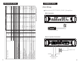
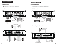
SERIES
800.4
3000.1
5000.1
FULL RANGE
4-CH POWER AMPLIFIER
1 OHM-STABLE D CLASS
FULL DIGITAL
MONOBLOCK AMPLIFIER
Congratulations
on your selection of a RE Audio
series amplifier.
We take pride in manufacturing our products and you can expect
your new amplifier to give you years of trouble-free service.
To make your installation as easy and reliable as possible, please
read this manual carefully before beginning.
If you need more information, your RE Audio Dealer will be glad to
help. To locate a RE Audio Dealer near you, go to our web site and
look for “Locate Dealer”.
CONTENTS
1 •••••••••••••
Congratulations / TOC
2 •••••••••••••
Features & Installation
3 •••••••••••••
Wiring Instructions
4 •••••••••••••
Basic Wiring
• Monoblock
• 4-channel
6 •••••••••••••
Bridged Wiring
• 4-channel
1
7 •••••••••••••
Specifications
8 •••••••••••••
Troubleshooting
9 •••••••••••••
Caution
10 •••••••••••
Limited Warranty
Limited Warranty:
RE Audio warrants all manufactured electronic products to be free from defects in
material and workmanship for a period not to exceed ONE YEAR from the date of
purchase.
IMPORTANT WARRANTY NOTICE: RE Audio will only warrant and service
products displaying valid RE Audio serial numbers. WARRANTY SERVICE
WILL ONLY BE PERFORMED WHEN THE UNIT IS ACCOMPANIED BY A
COPY OF THE ORIGINAL SALES RECEIPT FROM AN AUTHORIZED
DEALER. All product returned to RE Audio for service MUST be accompanied
by a Return Authorization Number, issued by RE Audio in advance of
shipment. The Return Authorization Number must be clearly and conspicuously displayed on the shipping carton or RE Audio will refuse delivery.
For Return Authorization Numbers, first call your RE Audio dealer you purchased the
products from. The dealer will help you to obtain Return Authorization Numbers.
This warranty extends only to the original purchaser and is not transferable. Defective
equipment must be returned within the warranty period, freight prepaid, to the RE
Audio Factory or an Authorized RE Audio Warranty Station.
This warranty covers only detects in materials and workmanship of manufactured
electronic products(amplifiers). Incidents of misuse, abuse, neglect, or unauthorized
modification will not be covered within the terms of this warranty.
RE Audio reserves the right to refuse warranty service under such conditions.
RE Audio WILL NOT BE RESPONSIBLE FOR ANY DAMAGES, WHETHER
INCIDENTAL OR CONSEQUENTIAL, RELATED TO THE USE OF THIS OR
ANY OTHER PRODUCT BEARING OR SOLD UNDER THE RE Audio
BRAND NAME. USE THIS PRODUCT AT YOUR OWN RISK. IMPROPER
USE OF THIS PRODUCT CAN RESULT IN PROPERTY DAMAGE, BODILY
HARM, AND OR OTHER DAMAGE. RE Audio ASSUMES NO RESPONSIBILITY FOR YOUR HEALTH OR SAFETY.
10
Caution !
Jump starting your vehicle can cause large voltage spikes within your
automobile’s electrical system. To prevent damage to your stereo
system, make sure the entire system is shut down until full battery
charge has been reached and jumper cables have been removed from
the battery.
We want you listening for a lifetime!
Used wisely, you new
will provide a lifetime of fun and enjoyment.
Since hearing damage from loud sound is often undetectable until it is too
late, RE Audio and the Electronic Industry Association’s Consumer Electronics Group recommend you avoid prolonged exposure to excessive loud
sound.
dB level
30
40
50
60
70
80
Examples
Quiet library, soft whispers
Living room, refrigerator, away from traffic
Light traffic, normal conversation, quiet office
Air conditioner at 20 feet, sewing machine
Vacuum cleaner, hair dryer, noisy restaurant
Average city traffic, garbage disposal, alarm clock at 2 feet
The following noises can be dangerous under constant exposure
90
100
120
140
180
Subway, motorcycle, truck traffic, lawn mower
Garbage truck, chain saw, pneumatic drill
Rock band concert in front of speakers, thunderclap
Gunshot blast, jet plane
Rocket launching pad
Information courtesy of the Deafness Research Foundation
9
FEATURES
• Low Pass Frequency control
• Gain control
• Sub Sonic control
• Bass Boost control
• Low Level input
• Bass Frequency control
• MOSFET power supply
• Time delay turn on
• Thermal, short circuit protection
• Remote Turn-on/off circuit
• LED power and protection indicator
INSTALLATION
• Please choose a mounting place without any direct weather influences.
Note that the amplifier generates heat so a well ventilated place is
necessary.
• Use at least 8-gauge wire for power and ground connections
• Use at least 12-gauge wire for speaker connections
• Use at least 16-gauge wire for remote connection
• Keep the wire connections as short as possible in order to minimize power
loss and provide a higher audio out quality
• Use the shortest ground connection to the chassis of the vehicle and
make sure that the paint is removed at the connection point
• Connect the remote input to the remote/antenna output of the head unit
• Mount the fuse holder within 200mm(8”) of the vehicle’s battery. Use a
fuse equal to that specified for your amplifier if a large, single +12V line is
run which feeds more than one amplifier add up all required fuse ratings
and use the total rating for the fuse
• Connect the speaker to the amplifier observing the correct phasing.
Make sure that none of the speaker connections can touch the vehicle
chassis
• Connect the RCA inputs to the appropriate signal source using only the
highest quality RCA cables
• Make sure that the RCA and speaker cables do not run parallel to the
+12V wiring
2
WIRING INSTRUCTIONS
Power Connection
The battery terminal(+12V) must be connected directly to the positive terminal of the
vehicle’s battery to provide an adequate voltage source and minimize noise. Connecting
the battery terminal lead to any other point(such as the fuse block) will reduce the power
output and may cause noise and distortion. Use only 8 AWG or thicker(smaller AWG) wire
for this lead and connect it to the terminal of the battery after all other wiring is completed.
Ground Connection
The ground terminal(GND) connection is also critical to the correct operation of the
amplifier. Use a wire of the same gauge as the power connection(8 AWG or thicker) and
connect it between the ground terminal(GND) of the amplifier and a metal part of the
vehicle close to the mounting location. This wire should be as short as possible and any
paint or rust at the grounding point should be scraped away to provide a clean metal
surface to which the end of the ground wire can be screwed or bolted.
Remote Turn-on Connection
The amplifier is turned on by applying +12V to the remote turn-on terminal(REM).
The wire lead to this terminal should be connected to the “Auto-Antenna” lead from the
head unit. If the head unit does not provide an “Auto-Antenna” lead, the remote turn-on
lead may be wired to an “Accessory” or “Radio” terminal in the vehicle’s fuse block. This
will turn the amplifier on or off with the ignition key regardless of whether the head unit is
on or off. The remote turn-on lead does not carry large currents. So 20 AWG wire may be
used for this application.
Speaker Connection
Depending on the type and number of speakers, connect them to the speaker terminals
as shown in the appropriate wiring diagram. For most applications, 16 AWG wire would
be adequate, but in no case thinner than 18 AWG. For leads more than 10 feet long, 14
AWG is recommended. When wiring the speakers, pay special attention to the polarity of
the terminals. Do not ground any speaker leads to the chassis of the vehicle.
Input Connection
Caution! Use either the low-level or high-level inputs on the amplifier. Do not use both at
the same time. If the head unit does not provide low-level outputs, the amplifier may be
connected via the speaker(high-level) outputs from the head unit. Wire the speaker leads
from the head unit to the 5-pin adaptor harness as shown in the diagram(shielded cable
is not required) and plug the connector into the input connector on the amplifier. Carefully
splice and insulate all wire connection.
3
Before removing your amplifier, refer to the list below and follow
the suggested procedures. Always test the speakers and their
wires first.
No Output
• Confirm that all terminal strip connections are secure and tight.
• Check both in-line and built-in fuses.
• Confirm that the audio signal source (car radio, equalizer, etc) is
connected and is supplying output signal. To check if the amplifier is
supplying signal, unplug the RCA cables from the signal source (but
leave them plugged into the amp) and briefly tap the center pin of each
of the disconnected RCA plugs with your finger. This should produce a
noise (feedback) in your speakers.
Only one channel works
• Confirm that all terminal strip connections are secure and tight.
• Check the “BALANCE” control on the head unit (or other source) to
verify that it is set to its mid point.
• If you are using the low-level RCA input, reverse the input plugs at the
amplifier (switch the R with the L). If the channel which is silent
switches to the other side, the problem is either in the head unit/other
source or the connecting cables.
Weak output
• Re-adjust the Input Level Control to better suit the input signal.
Noise in the audio
• If the noise is a “whine” whose pitch follows the engine speed,
confirm that the amplifier and any other signal sources (head unit,
equalizer, etc) are properly grounded.
• If the noise is a “clicking” or “popping” noise whose rate follows the
engine speed, this usually means that the vehicle is equipped with
resistor spark plugs and wires, or that the ignition is in need of service.
• Check the routing of the speaker and input wires to make sure they
are not adjacent to wires which interconnect with lights and other
accessories.
• If the above steps fail to improve or clear noise interference, the
system should be checked by a authorized RE Audio Dealer.
8
7
(W)9.45/240 x (H)2.44/62
Power Voltage Range
Protection (thermal, overload, short circuit, DC offset)
Fuse Rating
Dimensions [(L) in/mm]
Input Impedance
Input
Sensitivity
Gain Control
Wired Remote Control
Bass Frequency
Bass Boost Control @ 45Hz
Crossover Frequency
Power Band Width (Frequency Response)
Channel Separation @ 4Ω RMS
S/N Ratio
Total Harmonic Distortion
Power Output (RMS)
High Level
Low Level
High Pass
Subsonic
Low Pass
Input Short
4Ω
4Ω mono
1Ω
2Ω
4Ω
Hz
24dB
12dB
V
A
in/mm
KΩ
V
mV/V
dB
dB
Hz
Hz
24dB
Hz
dB
-3dB
1KHz/100Hz
4Ω
W
%
1KHz/100Hz
W
100Hz
1KHz/100Hz
W
@ 14.4V
30~80
0~12
—
0~18
11~15V
Yes
250A x 1¹
21.75/552
20
6
100
Yes
Yes
30~80
0~12
—
17~50
40~180
17~180
90
< 0.05
—
1 x 2500
1 x 1700
1 x 1000
5000.1
* Specification subject to change without notice
¹ External fuse must be used(at least 250A)
Yes
11~15V
35A x 4
35A x 2
Yes
14.75/375
14.06/357
11~15V
6
20
2
22
100
—
40~250
200
17~50
—
Yes
40~180
40~250
Yes
17~180
10~30K
—
90
90
Yes
—
1 x 1400
—
< 0.05
1 x 1000
4 x 110
<0.02
1 x 600
4 x 85
2 x 210
3000.1
800.4
SPECIFICATIONS
CONNECTIONS
[Basic Wiring]
Monoblock [ZTX² 3000.1/5000.1] Amplifiers
RCA Connection
3000.1
from OUTPUT of HEAD UNIT
Power & Speaker Connection
3000.1
Impedance: 2~8Ω
GROUND
+
to BATTERY
from REMOTE OUTPUT
of HEAD UNIT
4
CONNECTIONS
CONNECTIONS
[Basic Wiring]
[Bridged Wiring]
4-channel [ZTX² 800.4] Amplifiers
4-channel [ZTX² 800.4] Amplifiers
RCA Connection
RCA Connection
Ch2 Ch1
Ch3
Ch4
(Y-adapter)
from OUTPUT of
HEAD UNIT
HI INPUT
from OUTPUT of
HEAD UNIT
HI INPUT
Power & Speaker Connection
Impedance: 2~4Ω
Power & Speaker Connection
Impedance: 4~8Ω
800.4
800.4
to BATTERY
GROUND
5
+
from REMOTE OUTPUT
of HEAD UNIT
GROUND
Impedance: 2~4Ω
to BATTERY
+
from REMOTE OUTPUT
of HEAD UNIT
Impedance: 4~8Ω
6