1
1-36-96
"Only for internal use by Draeger. Not applicable as Instructions for Use!"
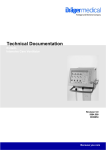
Julian
Anaesthetic Workstation
Instructions for Use
Software 3.n
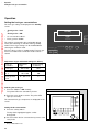
How to use these Instructions for Use
How to use these Instructions for Use
"Only for internal use by Draeger. Not applicable as Instructions for Use!"
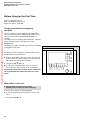
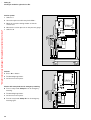
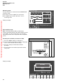
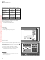
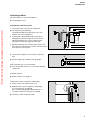
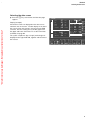
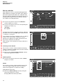
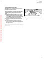
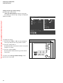
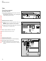
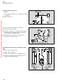
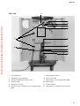
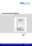
In the header is the subject…
of the main chapter.
Underneath is the title of the subchapter, to help you
find your way around quickly.
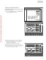
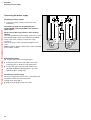
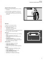
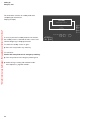
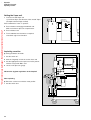
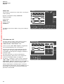
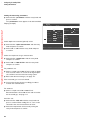
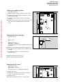
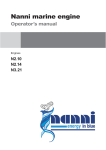
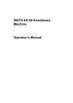
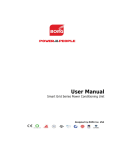
Operation
Selecting the ventilation mode
MAN/SPONT
1
Press the »MAN/SPONT« key,
2
and confirm with the rotary knob.
Julian
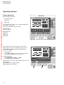
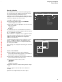
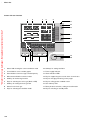
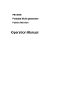
On each page…
the instructions for use
combining text with illustrations. The information is
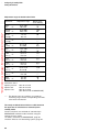
translated directly into actions to enable the user to
learn „hands-on“ how to use the workstation.
Left-hand column: the text…
provides explanations and guides the user clearly and
ergonomically with brief directions on the use of the
product.
Bullet points indicate the steps to be followed, and
where there are several steps, numbers refer to the
illustration and indicate the sequence.
2
1
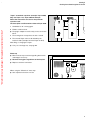
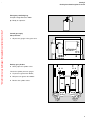
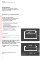
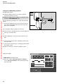
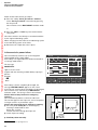
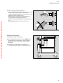
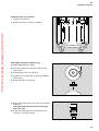
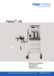
Display (example):
MAN/SPONT
Pleth
SpO2
40
MV
0
O2
VT
0.65
--
N2O
0
0
Start volumeter: Confirm
O2 %
L/min
50 4.00
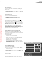
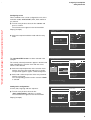
Screen displays guide the user and confirm the steps
to be followed.
0.5
1
Volumeter --s
Freshgas O2 + N2O
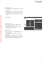
Right-hand column: the illustration…
provides the link with the text and serves as a guide
to the workstation. Points mentioned in the text are
emphasised and non-essential information is omitted.
etCO2
CO2
Enf.
5
10
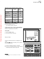
!
freshgas
internal
external
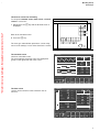
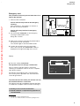
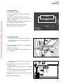
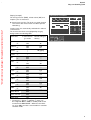
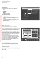
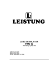
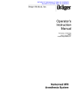
O2 flush
–
For flushing and rapidly filling the breathing
system and breathing bag with O2 while
bypassing the Vapor unit.
3
Press the »O2 +« button.
O2 flows into the breathing system without
anaesthetic gas as long as the button is held
down.
3
2
Iso.
98
38
5.2
67
FiCO2
_
freq
8
Fi
Fet
45
53
0.8
0.6
41
51
0.6
0.5
MAC (age: 36)
1.3
alarm
limits
CO2-al.
on/off
alarm
info
list
curves
config.
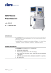
Contents
"Only for internal use by Draeger. Not applicable as Instructions for Use!"
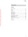
Contents
For Your Safety and that of Your Patients
5
Intended Use
7
Operating Concept
11
Before Using for the First Time
19
Preparation
21
Starting Up
25
Operation
35
Monitoring
55
Configuring in Standby Mode
81
Care
97
Julian as Wall-mounted Unit
115
Maintenance Intervals
117
Fault – Cause – Remedy
121
What's what
127
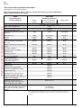
Technical Data
133
Abbreviations / Symbols
141
Index
144
3
4
"Only for internal use by Draeger. Not applicable as Instructions for Use!"
For Your Safety and that of Your Patients
For Your Safety and that of Your
Patients
"Only for internal use by Draeger. Not applicable as Instructions for Use!"
Strictly follow the Instructions for Use
Any use of the apparatus requires full understanding and
strict observation of these instructions.
The apparatus is only to be used for purposes specified
here.
Maintenance
The apparatus must be inspected and serviced regularly
by trained service personnel at six monthly intervals
(and a record kept).
Repair and general overhaul of the apparatus may only
be carried out by trained service personnel.
We recommend that a service contract be obtained with
DrägerService and that all repairs also be carried out by
them. Only authentic Dräger spare parts may be used for
maintenance.
Observe chapter "Maintenance Intervals".
Accessories
Do not use accessory parts other than those in the
order list.
Not for use in areas of explosion hazard
This apparatus is neither approved nor certified for use in
areas where combustible or explosive gas mixtures are
likely to occur.
Safe connection with other electrical equipment
Electrical connections to equipment which is not listed in
these Instructions for Use should only be made following
consultations with the respective manufacturers or an
expert.
Liability for proper function or damage
The liability for the proper function of the apparatus is
irrevocably transferred to the owner or operator to the
extent that the apparatus is serviced or repaired by
personnel not employed or authorized by DrägerService
or if the apparatus is used in a manner not conforming to
its intended use.
Dräger cannot be held responsible for damage caused
by non-compliance with the recommendations given
above. The warranty and liability provisions of the terms
of sale and delivery of Dräger are likewise not modified
by the recommendations given above.
Dräger Medizintechnik GmbH
5
6
"Only for internal use by Draeger. Not applicable as Instructions for Use!"
Intended Use
Contents
Intended Use
Contents
"Only for internal use by Draeger. Not applicable as Instructions for Use!"
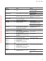
Intended Use............................................................................................. 9
7
8
"Only for internal use by Draeger. Not applicable as Instructions for Use!"
Intended Use
Intended Use
Julian Anaesthetic Workstation for patients with a body
weight of 5 kg and over with the use of IPPV ventilation.
For the use of:
Monitoring
by means of adjustable alarm limits that are automatically
adapted to the ventilation mode.
"Only for internal use by Draeger. Not applicable as Instructions for Use!"
– Inhalation anaesthesia in rebreathing systems
– Inhalation anaesthesia in semi-closed to virtually
closed systems with "low flow" and "minimal flow"
techniques (for minimal gas and anaesthetic agent
consumption).
The workstation may only be used under the
supervision of qualified medical personnel, so that
assistance can be provided immediately in the event
of any malfunctions.
– Inhalation anaesthesia in non-rebreathing systems,
with separate fresh gas outlet for the connection of
e.g. the Bain system or Magill system
with a fresh gas flow of 0.5 to 12 L/min.
Ventilation modes:
– Automatic ventilation (IPPV)
and
pressure-controlled ventilation (PCV).
– Manual ventilation (MAN).
– Spontaneous ventilation (SPONT).
The following measured values are displayed:
– Peak pressure, mean pressure, plateau pressure and
PEEP
Explosive anaesthetics, such as ether or cyclopropane, must not be used due to the risk of fire.
Mobile radio telephones must not be used within
10 metres of the workstation!
Mobile telephones may interfere with the operation of
electrical and electronic medical equipment.*
Julian must not be used with nuclear spin
tomography (MRT, NMR, NMI)!
Operation of the apparatus may be impaired.
– Expiratory minute ventilation
Tidal volume VT
Breathing rate
Patient compliance
– Inspiratory and expiratory concentration of O2, N2O,
anaesthetic gas and CO2
optional:
– Functional oxygen saturation (SpO2) and pulse rate.
The following parameters are displayed as curves:
– Airway pressure
– Expiratory flow
– Inspiratory and expiratory concentration of O2, CO2
and anaesthetic gas
optional:
– Plethysmogram
Trend curves and measured value lists are also available.
*
Dräger medical equipment fulfils the interference resistance
requirements according to the product-specific standards or
EN 60601-1-2 (IEC 601-1-2). However, depending on the design
of the mobile phone and circumstances of use, field strengths
may occur in the immediate environment of a mobile phone that
exceed the limits of the above standards and therefore cause
interference.
9
10
"Only for internal use by Draeger. Not applicable as Instructions for Use!"
Operating Concept
Contents
Operating Concept
"Only for internal use by Draeger. Not applicable as Instructions for Use!"
Contents
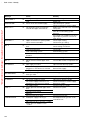
Screen ergonomics.................................................................................12
Selecting / setting ventilation parameters.................................................. 14
Selecting / setting monitoring functions.....................................................15
Screen layout.......................................................................................... 16
Three basic screens for monitoring........................................................... 17
The standard screen.................................................................................17
The data screen....................................................................................... 17
The trend screen...................................................................................... 18
11
Operating Concept
Screen ergonomics
Operating Concept
Screen ergonomics
Monitoring
All the settings required for
IPPV
– Fresh gas delivery
Pleth
"Only for internal use by Draeger. Not applicable as Instructions for Use!"
etCO2
CO2
– Monitoring
are entered on the system screen using the appropriate
keys and the rotary knob.
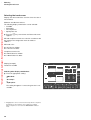
The keys are grouped in function fields:
Left-hand field
Fresh gas delivery
40
MV
0
Freshgas O2+N2O
O2 %
L/min
50 4.00
Pmax
Fet
45
53
0.8
0.6
41
51
0.6
0.5
Freq.
TI:TE
1/min
MAN
SPONT
IPPV
list
..
12...
curves
config.
1.3
TIP:TI
PEEP
%
mbar
25 600 10 1:2.0 10
AIR
N 2O
VT
mL
mbar
0
PCV
Ventilation
IPPV
Pleth
SpO2
etCO2
CO2
MV
O2
0
PAW
20
N2O
Iso.
Enf.
0
98
67
38
6.0
freq
alarm
limits
auto set
limits
10
alarm
info
Fi
Fet
45
53
0.8
0.6
41
51
0.6
0.5
MAC (age: 36)
Freshgas O2+N2O
O2 %
L/min
50 4.00
AIR
N 2O
1
12
alarm
info
Fi
MAC (age: 36)
40
These function keys are located in the bottom row on the
control panel.
Left-hand block for fresh gas setting
Right-hand block for ventilation
freq
10
Enf.
0
The main functions for anaesthesia, e.g. selection of
N2O or AIR, or selection of ventilation modes, can be
selected directly by keys with permanently defined
functions ("hardkeys"):
2 Right-hand block
The »MAN SPONT«, »IPPV« or »PCV«
keys select the ventilation mode.
38
6.0
alarm
limits
auto set
limits
N2O
Iso.
Fresh gas
delivery
1 Left-hand block
The »N2O« or »AIR« keys are used to select the gas
to be mixed with O2 for the fresh gas mix.
67
O2
PAW
20
Right-hand field
Ventilation
Middle field
Monitoring
98
SpO2
– Ventilation
Pmax
mbar
VT
mL
Freq.
TI:TE
1/min
IPPV
2
PCV
curves
config.
1.3
TIP:TI
PEEP
%
mbar
35 600 10 1:2.0 10
MAN
SPONT
list
0
..
12...
Operating Concept
Screen ergonomics
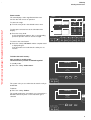
Complementary "softkeys" with variable functions are
provided at the bottom edge of the screen, above each
group of hardkeys. These softkeys are used to set the
fresh gas delivery parameters and ventilation parameters.
IPPV
Pleth
etCO2
CO2
40
1 Left-hand block:
The keys for setting the O2 concentration and fresh
gas flow.
MV
0
N2O
"Only for internal use by Draeger. Not applicable as Instructions for Use!"
Freshgas O2+N2O
O2 %
Pmax
mbar
L/min
50 4.00
VT
mL
Fi
Fet
45
53
0.8
0.6
41
51
0.6
0.5
Freq.
N 2O
TI:TE
1/min
alarm
limits
auto set
limits
alarm
info
list
..
12...
curves
config.
1.3
TIP:TI
PEEP
%
mbar
35 600 10 1:2.0 10
1
0
2
MAN
SPONT
AIR
IPPV
PCV
IPPV
In a prominent position at the bottom right-hand side:
Pleth
SpO2
etCO2
CO2
40
MV
0
O2
PAW
20
– to set and confirm the parameters for fresh gas and
ventilation modes,
freq
MAC (age: 36)
The current parameter values are displayed in the softkey
field.
– to confirm the selected carrier gas or a ventilation
mode,
10
Enf.
These softkeys have different functions, depending on
the operating status or ventilation mode.
4 confirm = press
38
6.0
Iso.
2 Right-hand block:
The keys for setting the parameters for the relevant
ventilation mode. The example shows the parameters
for IPPV controlled ventilation.
3 select = turn
67
O2
PAW
20
0
The "turn-and-push" rotary knob
is the main operating control of the apparatus and has the
following functions in all setting operations:
98
SpO2
N2O
Iso.
Enf.
0
98
67
38
6.0
10
Fi
Fet
45
53
0.8
0.6
41
51
0.6
0.5
MAC (age: 36)
Freshgas O2+N2O
O2 %
L/min
50 4.00
Pmax
mbar
VT
mL
Freq.
TI:TE
1/min
AIR
MAN
SPONT
alarm
info
list
..
12...
curves
config.
1.3
TIP:TI
PEEP
%
mbar
35 600 10 1:2.0 10
– to set and confirm the monitoring functions.
N 2O
freq
alarm
limits
auto set
limits
0
3
IPPV
PCV
Beside the rotary knob:
The standby key E for switching over to standby mode.
5 Press standby key E and confirm by pressing the
rotary knob.
5
4
13
Operating Concept
Screen ergonomics
Selecting / setting ventilation parameters
Julian
Example: PEEP ventilation parameter
1 Press the softkey »PEEP«.
2 Select the PEEP value = turn the rotary knob.
"Only for internal use by Draeger. Not applicable as Instructions for Use!"
3 Confirm the PEEP value = press the rotary knob.
1
2
3
The keys for the various monitoring functions are located
on the right-hand side of the screen.
IPPV
Pleth
SpO2
These keys also have different functions = softkeys,
depending on the monitoring screen required.
etCO2
CO2
40
MV
O2
0
PAW
20
N2O
Iso.
Enf.
0
98
67
38
6.0
freq
alarm
limits
auto set
limits
10
alarm
info
Fi
Fet
45
53
0.8
0.6
41
51
0.6
0.5
MAC (age: 36)
Freshgas O2+N2O
O2 %
L/min
50 4.00
N 2O
14
AIR
Pmax
mbar
VT
mL
Freq.
TI:TE
1/min
IPPV
PCV
curves
config.
1.3
TIP:TI
PEEP
%
mbar
35 600 10 1:2.0 10
MAN
SPONT
list
0
..
12...
Operating Concept
Screen ergonomics
Selecting / setting monitoring functions
Julian
For example, to change the lower alarm limit of the endtidal CO2 concentration.
1
"Only for internal use by Draeger. Not applicable as Instructions for Use!"
1 Press the »alarm limits« softkey. The alarm limits
menu is displayed on the screen.
IPPV
Pleth
SpO2
CO2
etCO2
40
MV
0
FiO2
PAW
20
FiHal.
-95
98
67
38
6.0
29
0.8
120
50
42
30
auto set
limits
alarm
info
-3.0
list
-20
curves
1.0
0.0
0
alarm
limits
config.
40
8
PAW
Select limit: Turn and confirm ! !
Freshgas O2 + N2O
Pmax
O2 %
50 1.00
●
Freq.
TIP:TI
PEEP
%
mbar
25 600 10 1:2.0 10
0
IPPV
Pleth
Set the alarm limit value = turn the rotary knob.
SpO2
●
TI:TE
1/min
Select the alarm limit value = turn the rotary knob.
Confirm the selection = press the rotary knob.
The limit value is highlighted.
Example: lower alarm limit etCO2: <30
●
VT
mL
mbar
L/min
Confirm the new alarm limit = press the rotary knob.
The cursor returns to the zsymbol.
CO2
etCO2
40
MV
0
FiO2
PAW
20
FiHal.
-95
98
67
38
6.0
29
0.8
120
50
42
30
-3.0
-20
1.0
0.0
0
auto set
limits
alarm
info
list
curves
config.
40
8
PAW
Select limit value: Turn and confirm
alarm
limits
!
Freshgas O2 + N2O
O2 %
L/min
50 1.00
Pmax
VT
Freq.
mbar
mL
1/min
TI:TE
TIP:TI
PEEP
%
mbar
25 600 10 1:2.0 10
0
15
Operating Concept
Screen ergonomics
Screen layout
Exit the alarm limits menu:
Julian
"Only for internal use by Draeger. Not applicable as Instructions for Use!"
1 Press the rotary knob
or
2 Press the Q key.
2
1
The function keys for standard functions are located on
the right-hand side of the control panel.
IPPV
Pleth
98
SpO2
G Suppress the acoustic alarm for 2 minutes.
S Select the screen page.
Q Back to standard page.
etCO2
CO2
40
MV
38
6.0
O2
0
PAW
20
N2O
Iso.
Enf.
0
67
O2 %
Pmax
mbar
L/min
50 4.00
N 2O
Screen layout
➀ Status field:
Freq.
MAN
SPONT
AIR
45
53
0.8
0.6
41
51
0.6
0.5
TI:TE
1/min
IPPV
➃ Numerical value field:
For numerical values
➄ Lower softkeys – for fresh gas parameters
➅ Prompt field:
For user guidance
➆ Lower softkeys – for ventilation parameters
➇ Right-hand softkeys – for monitoring:
For rapid selection of the desired monitoring function
16
..
12...
curves
config.
1.3
TIP:TI
PEEP
%
mbar
➂
0
➃
IPPV
Pleth
SpO2
For curves and bargraphs
Displays information on the alarms, warnings, etc.
and their priority
list
PCV
➁
➁ Graphics field:
➂ Alarm field:
alarm
info
Fet
35 600 10 1:2.0 10
➀
Displays information on the current operating mode
VT
mL
10
Fi
MAC (age: 36)
Freshgas O2+N2O
freq
alarm
limits
auto set
limits
etCO2
CO2
40
MV
O2
0
PAW
20
N2O
Iso.
Enf.
0
98
38
6.0
O2 %
L/min
50 4.00
➄
Pmax
VT
mbar
mL
Freq.
1/min
freq
10
Fi
Fet
45
53
0.8
0.6
41
51
0.6
0.5
MAC (age: 36)
Freshgas O2+N2O
67
TI:TE
➆
auto set
limits
alarm
info
list
curves
config.
1.3
TIP:TI
PEEP
%
mbar
35 600 10 1:2.0 10
➅
alarm
limits
0
➇
Operating Concept
Screen layout
Three basic screens for monitoring
To call up the standard screen, data screen and trend
screen in succession:
Julian
"Only for internal use by Draeger. Not applicable as Instructions for Use!"
1 Briefly press the S key until the desired screen is
displayed.
2
1
Back to the standard screen:
2 Press the Q key.
The fresh gas and ventilation parameters can be set by
means of the softkeys in each of the three basic screens.
The standard screen
with three selectable curves.
The most important numerical values are displayed in
groups on the right-hand side of the screen.
IPPV
Pleth
98
SpO2
etCO2
CO2
40
MV
38
6.0
O2
0
PAW
20
N2O
Iso.
Enf.
0
67
freq
10
Fi
Fet
45
53
0.8
0.6
41
51
0.6
0.5
O2 %
L/min
50 4.00
The data screen
contains all the numerical values with their units of
measure.
Pmax
VT
mL
mbar
Freq.
TI:TE
auto set
limits
alarm
info
list
curves
config.
1.3
MAC (age: 36)
Freshgas O2+N2O
alarm
limits
TIP:TI
PEEP
%
mbar
1/min
25 600 10 1:2.0 10
0
IPPV
PAW
peak
plat.
40
PEEP
mean
compliance
27
20
5
15
65
mbar
6.0
VT
0.60
freq
10
AW-temp.
34
0
98
67
1/min
Fi
Fet
0
40
58
0.8
0.4
MAC (age: 36)
36
33
56
0.6
0.5
1.3
1/min
15. Dec. 99
12 : 00
°C
sys. comp. 6.40 mL/mbar
leckage
10 mL/min
mbar
CO2
mmHg
mbar
O2 %
mL/mbar
N2O %
20
MV
SpO2
%
mbar
Iso. %
L/min
Enf. %
L
alarm
limits
auto set
limits
alarm
info
list
config.
01-10
8 : 00
Freshgas O2 + N2O
Pmax
O2 %
L/min
50 1.00
mbar
VT
mL
Freq.
1/min
TI:TE
TIP:TI
PEEP
%
mbar
25 600 10 1:2.0 10
0
17
Operating Concept
Screen layout
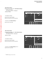
The trend screen
displays the recorded progress of the numerical values
over time since measurement started. The current
measured values are displayed on the right-hand side.
IPPV
PAW
60
SpO2
40
0
11:00
"Only for internal use by Draeger. Not applicable as Instructions for Use!"
20
0
98
67
30
etCO2
Display (example):
Trends for CO2 and minute ventilation MV
CO2
12:00
13:00
MV
MV
15
O2
10
N2O
Iso.
Enf.
5
38
6.0
freq
AGas
N 2O
Fi
Fet
45
53
0.8
0.6
41
51
0.6
0.5
O2
compl.
Zoom in: Press
!
CO2
MV
10
SpO2
pulse
full
trend
1.3
MAC (age: 36)
0
Select zoom area: Turn
alarm
limits
!
Freshgas O2 + N2O
O2 %
L/min
50 1.00
18
Pmax
VT
Freq.
mbar
mL
1/min
TI:TE
TIP:TI
PEEP
%
mbar
25 600 10 1:2.0 10
0
Before Using for the First Time
Contents
Before Using for the First Time
Contents
"Only for internal use by Draeger. Not applicable as Instructions for Use!"
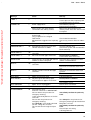
Charging the battery for emergency operation...................................... 20
When Julian is not in use........................................................................ 20
19
Before Using for the First Time
Charging the battery for emergency operation
When Julian is not in use
Before Using for the First Time
"Only for internal use by Draeger. Not applicable as Instructions for Use!"
Fit the enclosed O2 sensor,
page 119 "Replacing O2 sensor"
Fit the flow sensor, page 108.
Charging the battery for emergency
operation
Julian has a built-in uninterruptible power supply UPS
which maintains the power supply for 30 minutes in the
event of a mains failure, provided that the battery is
charged.
The switch-over to the battery-powered UPS is automatic
and is indicated on the screen by the message:
POWER FAIL!
The battery recharges automatically when the workstation
is plugged into the mains.
1
The battery must be charged for 10 hours before using
the Workstation for the first time.
●
Plug the mains plug of the Julian workstation into the
mains socket. The mains voltage must correspond to
the voltage specified on the nameplate.
1 The green LED N lights up.
●
Leave Julian connected to the mains for 10 hours.
The workstation does not have to be switched on.
The devices connected to auxiliary power sockets will
not be powered by the UPS in the event of a power
failure.
When Julian is not in use
●
Charge battery at least every 4 weeks.
Allowing it to run down can lead to damage.
If Julian is out of use for an extended period:
●
Leave the workstation connected to the mains at all
times.
1 The green LED N is lit.
20
Preparation
Contents
Preparation
"Only for internal use by Draeger. Not applicable as Instructions for Use!"
Contents
Connecting the gas supply..................................................................... 22
Connecting the backup gas cylinders for O2 and N2O .............................23
Caution when handling O2 cylinders......................................................... 23
Connecting the anaesthetic gas scavenging system............................. 23
Connecting the power supply................................................................. 24
Connecting auxiliary systems.................................................................... 24
Equipotential bonding............................................................................... 24
Connecting the power supply................................................................... 24
21
Preparation
Connecting the gas supply
Preparation
Use only cleaned and disinfected parts!
"Only for internal use by Draeger. Not applicable as Instructions for Use!"
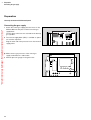
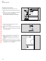
Connecting the gas supply
1 Screw the central gas supply pressure hoses for O2,
AIR and N2O into the ports on the back of the gas
supply block.
The two ports at the front are reserved for the backup
gas cylinders.
1
2
N2O AIR O2 VAC
2 The vacuum supply block (VAC) is available as option
for secretion aspiration.
Plug the other end of the pressure hoses into the wall
supply points.
●
Make sure the gas pressures of the central gas
supply are between 2.7 and 5.5 bar:
D
Julian
3 All three pressure gauges in the green zone.
3
22
Preparation
Connecting the gas supply
Connecting the anaesthetic gas scavenging system
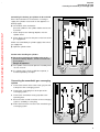
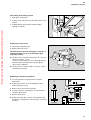
Connecting the backup gas cylinders for O2 and N2O
Even if the workstation is connected to a central gas
supply, the cylinders must remain on the apparatus as
backup supply.
"Only for internal use by Draeger. Not applicable as Instructions for Use!"
●
2
2
On the back of the workstation:
place full cylinders in the cylinder holders and secure
in position.
1 Screw the pressure reducing adapters onto the
cylinder valves.
2 Screw the gas hoses into the ports on the front of the
gas supply block.
1
1
Switch over immediately to cylinder supply if the central
gas supply fails:
●
Open the cylinder valves.
Caution when handling O2 cylinders
●
Do not oil or grease the O2 cylinder valves or O2
pressure reducing adapters, and do not handle with
greasy fingers.
Danger of explosion!
●
The cylinder valves must be opened / closed by hand.
Do not use tools.
●
If a cylinder valve is leaky or difficult to operate, it
must be repaired by an expert.
N2O
O2
Connecting the anaesthetic gas scavenging
system
3 Connect the transfer hose to the waste gas port and
to the port of the scavenging system.
3
4 Connect the scavenging hose to the port of the
scavenging system.
3
5 Connect the anaesthetic waste gas probe to the
aspirating hose.
5
6 Ensure that the second connection to the scavenging
system is sealed by a screw plug.
●
Follow the Instructions for Use of the anaesthetic gas
scavenging system.
6
3
4
23
Preparation
Connecting the power supply
Connecting the power supply
Connecting auxiliary systems
1
"Only for internal use by Draeger. Not applicable as Instructions for Use!"
1 connect to auxiliary sockets on the back of the
workstation.
The auxiliary sockets are not powered by the
uninterruptible power supply UPS in the event of a
power failure!
Do not connect HF surgical devices to the auxiliary
sockets!
Connecting equipment to the auxiliary sockets may cause
the patient leakage current to rise above the permitted
values in the event of failure of a protective earth
conductor.
The risk of electric shock cannot be excluded in such
cases.
Additional power adapter sockets must not be connected
to the auxiliary sockets.
Equipotential bonding
e.g. for intracardial or intracranial operations.
2 Connect one end of the earth cable to one of the
connecting pins on the back of the workstation.
●
Connect the other end of the earth cable to the
specified equipotential bonding point, e.g. on the
operating table or ceiling lamp.
Connecting the power supply
The mains voltage must be the same as specified on the
nameplate on the back of the workstation.
Voltage range: 90 to 265 V
●
24
Plug the mains plug into the wall socket.
2
Starting Up
Contents
Starting Up
Contents
"Only for internal use by Draeger. Not applicable as Instructions for Use!"
Checking the workstation against the checklist.................................... 26
Switching on............................................................................................ 26
Gas pressures.........................................................................................29
Central gas supply................................................................................... 29
Backup gas cylinders............................................................................... 29
Suction system.........................................................................................30
O2 flush .................................................................................................. 30
O2 emergency metering........................................................................... 30
Preparing Julian for the self-test................................................................ 31
Self-test...................................................................................................31
Electronics............................................................................................... 31
Fresh gas mixer........................................................................................31
Ventilator and breathing system ............................................................... 31
System compliance................................................................................ 32
Leakage................................................................................................... 32
Emergency start......................................................................................33
25
Starting Up
Checking the workstation against the checklist
Starting Up
"Only for internal use by Draeger. Not applicable as Instructions for Use!"
Checking the workstation against
the checklist
D
Julian
Preconditions:
The workstation must be prepared as described on
pages 97 to 107 and assembled ready for operation as
described on pages 108 to 113.
The gas supply and power supply must be connected.
Switching on
1 Switch on Julian: press the power switch »
«.
1
Version without rotary knob for O2 emergency
metering:
After switching on, Julian delivers an O2 flow of 8 L/min*
for manual ventilation.
This O2 flow is switched off automatically by Julian as
soon as the »cancel test« key appears after
acknowledging the checklist.
The opening screen appears with the current software
version after about 10 seconds. Julian now loads its
software and tests its internal memory.
Technology for life
Julian
03.00
01-may-2000
Please wait !
The checklist is displayed after about 40 seconds.
●
If the self-test has to be interrupted, e.g. for a quick start
in an emergency:
●
●
Check-list Julian
Check the components as instructed in the checklist
on the screen.
Acknowledge the checklist:
Press the rotary knob.
After a few seconds, the »cancel test« softkey
appears on the right-hand edge of the screen.
Press the »cancel test« key. See "Emergency start"
on page 33 to continue.
Examine machine according to check-list prior to operation
Before commencing test, close y-piece, connect gas sample-line
and set APL valve to 30 Pa*100 (mbar) and "Man"
Vapor
Filling device
Vapor Mont
Interlock system
Handwheel set to zero,
fill level o.k.
correctly closed
Vaporiser present and locked
into position
non used vapor blocked
Watertrap
Gas scavenging system
Breathing system
Soda lime
Emergency breathing bag
Central gas supply
Back up cylinders
Suction unit
O2-Flush
level ok ?
connected and ready for use
complete (valve discs) and fixed in place
no colour change
present and functional
O2 pressure, AIR, N2O pressure, 2.7 kPa*100 (bar)
O2 pressure > 50 , N2O pressure > 30 kPa*100 (bar)
functional
audible flow, breathing bag fills
Julian o.k. according to check-list? Please confirm
* Can be set to 4 L/min by DrägerService
26
!
Starting Up
Checking the workstation against the checklist
"Vapor" anaesthetic vaporizer (example: Vapor 2000)
3
3
Only use Vapor 19.3, Vapor 2000 or Devapor.
Follow the Instructions for Use for the particular
vaporizer used.
0
The description and illustrations relate to Vapor 2000.
1
4
0
1
"Only for internal use by Draeger. Not applicable as Instructions for Use!"
1 Handwheel to "0" and engaged.
2 Filled to sufficient level.
●
The plug-in adapter must fit evenly on the connection
block.
2
2
3 The locking lever must point to the left = locked.
4 The unused Vapor unit must be locked by the
interlock slider (example: left-hand Vapor locked).
After filling or changing the Vapor:
●
Carry out a leakage test, see page 48.
Water trap
●
Remove water trap container by pulling downwards
and empty if necessary.
●
Observe the hygiene regulations of the hospital.
●
Replace container from below.
When using the "Waterlock" water trap
●
See separate Instructions for Use
27
Starting Up
Checking the workstation against the checklist
AGS anaesthetic gas scavenging system
1 The transfer hose from the waste gas port must be
connected.
"Only for internal use by Draeger. Not applicable as Instructions for Use!"
2 The scavenging hose must be connected;
the anaesthetic waste gas probe must be plugged
into the Dräger wall socket and the indicator must be
green.
3 The float must be between the two marks.
1
2
1 2
3
Breathing system
●
Complete and engaged, with both valve discs
inserted, bellows fitted and hoses securely
connected.
●
Soda lime renewed, no violet discoloration.
28
Starting Up
Checking the workstation against the checklist
Emergency ventilating bag
Example: Dräger Resutator 2000
"Only for internal use by Draeger. Not applicable as Instructions for Use!"
●
Ready for operation.
Central gas supply
Gas pressures:
1 All pressure gauges in the green zone.
D
Julian
1
Backup gas cylinders
2 Slowly open the cylinder valves.
4 2
2 3
Check the cylinder pressure gauges:
3 O2 pressure greater than 50 bar,
4 N2O pressure greater than 30 bar.
2 Reclose the cylinder valves.
N2O
O2
29
Starting Up
Checking the workstation against the checklist
Suction system
D
Julian
1 Switch to I.
2 Set suction pressure with rotary knob »Vac.«.
3 Block the secretion viewing window or kink the
suction hose.
"Only for internal use by Draeger. Not applicable as Instructions for Use!"
4 Measure the suction pressure on the pressure gauge.
1 Switch to 0.
4
1
3
O2 flush
2
D
Julian
5 Press »O2 +« button.
6 The breathing bag inflates.
7 O2 flows from the Y-piece.
Version with rotary knob for O2 emergency metering
8 5
8 Turn on rotary knob »Safety O2« for O2 emergency
metering.
6 The breathing bag inflates.
7 O2 flows from the Y-piece.
8 Turn off rotary knob »Safety O2« for O2 emergency
metering again.
30
7
6
Starting Up
Checking the workstation against the checklist
Preparing Julian for the self-test
●
2
Make sure that the breathing system is securely
connected.
2
1 Close the Y-piece = plug firmly on to the cone.
"Only for internal use by Draeger. Not applicable as Instructions for Use!"
2 Ensure that the sample line is connected to the
Y-piece and to the water trap on the back of the
workstation.
1
Self-test
If all points on the checklist are OK:
●
Confirm = press the rotary knob.
The self-test is started.
The self-test is run automatically
and takes 3 to 4 minutes.
3 Julian essentially carries out the following automatic
tests and actions, which are coded:
3
Electronics
– Testing and calibration (Zeroing) of gas metering
bench
– Testing and calibration of O2 sensor
– Testing of pressure sensor for airway pressure
measurement
– Testing the flow sensor
– Activating the default settings for alarm limits,
monitoring parameters and the default settings of
the ventilator and fresh gas settings
Self-test
ventilator
electronics
✓
24
✓
cancel
test
freshgas
mixer
Fresh gas mixer
–
–
–
–
Testing of gas supply O2, N2O, AIR
Testing of gas inlet valves
Testing of O2 emergency metering
Testing of fresh gas failure monitoring (optional)
Ventilator
–
–
–
–
–
–
Testing and calibration of PEEP/Pmax valves
Testing of safety valve
Testing of MAN/AUTO switch-over valve
Testing of breathing phase valve
Testing of internal pressure sensor
Determination of compliance and leakage
31
Starting Up
Checking the workstation against the checklist
System compliance
Julian determines the current system compliance.
Depending on the breathing hoses used, the system
compliance is 5 to 6 mL/bar.
"Only for internal use by Draeger. Not applicable as Instructions for Use!"
Leakage
Julian determines the current leakage of the breathing
system and breathing hoses.
The system tolerates leaks of up to 150 mL/min.
For leaks of more than 150 mL/min:
●
Check the components of the breathing system,
repair any leaks and repeat the leak test.
Possible causes of leaks include:
–
–
–
–
–
–
–
–
–
–
–
damaged breathing hoses
O2 sensor not connected, or incorrectly connected
gas measurement sensor line not connected
water trap not inserted
breathing bag perforated
Vapor not correctly connected / filling device open
absorber not firmly screwed into place
flow sensor not firmly screwed into place
breathing system not correctly used
microbe filter not firmly connected up
measured gas return connection is open
Self-test
ventilator
Display (example):
electronics
A tick (✓) indicates that the relevant test point has been
completed successfully.
The clock symbol u indicates the test stage is currently
in progress.
freshgas
mixer
✓
✓
system
compliance
72
✓
5.00 mL/mbar
cancel
test
leakage
16 mL/mbar
Malfunctions detected in the self-test and any gas failures
are displayed on the screen. Some malfunctions can be
accepted by confirming = pressing the rotary knob, for
example no AIR supply (AIR FAILURE!!!).
Other malfunctions need to be corrected before starting
up the workstation, for example no O2 supply
(O2 FAILURE!!!).
●
The progress of the self-test is shown on the bar
display.
Standby
Julian
leakage
test
03.00
01-may-2000
delete
trend
config.
Julian switches to standby after the self-test.
Operation with
Display:
Freshgas O2+N2O
O2 %
L/min
50 4.00
32
MAN
SPONT
,
IPPV
or
PCV
Starting Up
Emergency start
Emergency start
This procedure should only be used when there is no
time for the self-test!
D
Julian
"Only for internal use by Draeger. Not applicable as Instructions for Use!"
1 Switch on the workstation.
Version without rotary knob for O2 emergency
metering:
After switching on, Julian delivers an O2 flow of
8 L/min* for manual ventilation.
Version with rotary knob for O2 emergency
metering:
2 Set rotary knob »Safety-O2« for O2 emergency
metering to the desired O2 flow.
Range 0 to 12 L/min.
●
Wait for the software to be internally loaded and for
the electronics to be self-tested.
The checklist appears after about 40 seconds.
●
Confirm the checklist: press the rotary knob.
After a few seconds, the »Cancel test« softkey is
displayed on the right-hand edge of the screen.
1
2
Display:
Self-test
●
36
Press the softkey »Cancel test«.
The apparatus only runs through a minimal test.
Julian is ready for operation about 1 minute after
switching on. Calibration of the O2 sensor is complete
after about 2 minutes.
The leakage and compliance test is not performed.
The accuracy levels specified in the "Technical Data"
cannot be guaranteed.
ventilator
electronics
✓
cancel
test
freshgas
mixer
To prevent abuse of this facility, the self-test can only
be cancelled 10 times in succession.
The self-test cannot be cancelled the next time that Julian
is started and a complete self-test must be run through.**.
Cancelling a test can lead to malfunction.
● Greater attention is required during operation of
the workstation.
*
**
Can be set to 4 L/min by DrägerService
Can be set to unlimited self-test cancellation by DrägerService
33
Starting Up
Emergency start
The workstation switches to standby mode after
completing the minimal test.
Display (example):
Standby
First interruption of self-test
Julian
leakage
test
"Only for internal use by Draeger. Not applicable as Instructions for Use!"
03.00
01-may-2000
delete
trend
config.
Operation with
Freshgas O2
If no key is pressed in standby mode for two minutes,
the standby screen is switched off and a screen saver
with the Dräger logo is displayed instead.
To switch the standby screen on again:
●
Press the rotary knob or any other key.
To start Julian:
Version with rotary knob for O2 emergency metering:
●
Turn rotary knob for O2 emergency metering to 0.
●
Select fresh gas setting and ventilation mode.
See »Operation«, page 36 onwards.
34
O2 %
L/min
50 2.00
MAN
SPONT
,
IPPV
or
PCV
Operation
Contents
Operation
"Only for internal use by Draeger. Not applicable as Instructions for Use!"
Contents
Setting the fresh gas concentrations..................................................... 36
Adjustment ranges................................................................................... 36
Selecting the carrier gas...........................................................................36
Setting the O2 concentration.................................................................... 36
Setting the fresh gas flow......................................................................... 37
Selecting the ventilation mode............................................................... 37
MAN/SPONT ventilation mode................................................................. 37
Manual ventilation..................................................................................... 37
Spontaneous breathing.............................................................................37
Monitoring mode...................................................................................... 40
IPPV ventilation mode...............................................................................40
Starting IPPV............................................................................................41
PCV ventilation mode............................................................................... 43
Starting PCV............................................................................................ 44
Setting the Vapor unit............................................................................. 46
Aspirating secretion................................................................................ 46
Changing patients...................................................................................47
Changing soda lime................................................................................ 47
Leakage test........................................................................................... 48
Ventilating children................................................................................. 49
Connecting the breathing hoses............................................................... 49
Using non-rebreathing systems..............................................................50
In the event of a power failure................................................................52
In the event of a gas failure.................................................................... 53
In the event of a Major Hardware Fault.................................................. 53
End of Operation.....................................................................................54
35
Operation
Setting the fresh gas concentrations
Operation
Setting the fresh gas concentrations
"Only for internal use by Draeger. Not applicable as Instructions for Use!"
The fresh gas settings are displayed in the Standby
screen:
–
»Fresh gas O2 + N2O«
or
»Fresh gas O2 + AIR«
–
O2 concentration »O2 %«
–
Standby
Julian
leakage
test
03.00
01-may-2000
Fresh gas flow »L/min«
The settings correspond to the configurable default
values after switching on and after entering standby
mode. The fresh gas settings can be modified before
selecting the ventilation mode.
Fresh gas does not flow in standby mode. The fresh gas
flow is not enabled until a ventilation mode has been
started.
delete
trend
config.
Operation with
MAN
SPONT
,
IPPV
or
PCV
Freshgas O2+N2O
O2 %
L/min
50 4.00
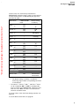
Adjustment ranges and default settings on delivery
Fresh gas
parameters
Carrier gas
O2 %
Fresh gas flow
L/min
Adjustment
range
Default setting
on delivery
AIR or N2O
N2O
25 to 100
100
0* ; 0,5 to 12
2
Selecting the carrier gas
1 Press the »N2O« or »AIR« hardkey.
The yellow LED in the selected key flashes.
●
Julian
Press the rotary knob to confirm. The yellow LED
lights up constantly.
The selected fresh gas components are displayed on the
screen.
Setting the O2 concentration
2
2 Press the softkey »O2%«.
The key field is highlighted against a white
background.
●
Set and confirm the O2 concentration by means of the
rotary knob.
*
Only in MAN/SPONT mode
36
1
Operation
Setting the fresh gas flow
Selecting the ventilation mode
MAN/SPONT
Setting the fresh gas flow
Julian
1 Press the softkey »L/min«.
The key field appears dark against a light background.
Set and confirm the fresh gas flow by means of the
rotary knob.
Julian is fitted with an electronic O2 minimum dosing
system to avoid hypoxic gas mixtures. For fresh gas flow
settings below 1 L/min, the O2 concentration is
automatically increased to a value corresponding to an
O2 flow of 250 mL/min. If this control system is
activated, the O2 value is highlighted in addition to the
active softkey »L/min«.
1
Version with fresh gas failure detection (optional):
During operation, Julian checks that the bellows are
sufficiently full.
If the message „Fresh gas ? !!“ appears:
●
Increase the fresh gas flow
The default settings valid whenever Julian is switched on
can also be modified; see "Setting default values" on
page 82.
Selecting the ventilation mode
MAN/SPONT ventilation mode
Choose between manual ventilation MAN and spontaneous breathing SPONT on the APL pressure-limiting
valve.
Manual ventilation
2 Set the lever of the APL pressure-limiting valve to
MAN.
2
MAN
3 Set the pressure limit = rotate lever.
MAN
3
Spontaneous breathing
4
SPONT
4 Set the lever of the APL pressure-limiting valve to
SPONT.
The valve is open for a free spontaneous breathing
stroke regardless of the set pressure limit.
SPONT
"Only for internal use by Draeger. Not applicable as Instructions for Use!"
●
37
Operation
Selecting the ventilation mode
MAN/SPONT
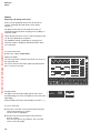
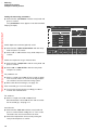
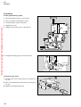
1 Press the »MAN/SPONT« key,
Julian
"Only for internal use by Draeger. Not applicable as Instructions for Use!"
2 and confirm with the rotary knob.
2
1
Display (example):
MAN/SPONT
Pleth
SpO2
etCO2
CO2
40
MV
0
O2
VT
0.65
--
N2O
0
0.5
Volumeter --s
0
Start volumeter: Confirm
Freshgas O2 + N2O
O2 %
Iso.
1
L/min
50 4.00
Enf.
5
98
38
5.2
FiCO2
_
freq
8
Fi
Fet
45
53
0.8
0.6
41
51
0.6
0.5
MAC (age: 36)
10
67
1.3
!
freshgas
internal
external
O2 flush
D
Julian
– For flushing and rapidly filling the breathing system
and breathing bag with O2 while bypassing the
Vapor unit.
3 Press the »O2 +« button.
O2 flows into the breathing system without
anaesthetic gas as long as the button is held down.
3
38
alarm
limits
CO2-al.
on/off
alarm
info
list
curves
config.
Operation
Selecting the ventilation mode
MAN/SPONT
Certain alarms are automatically switched off in
MAN/SPONT ventilation mode in order to avoid artefacts.
The deactivated alarms are identified by the grey background in the table.
"Only for internal use by Draeger. Not applicable as Instructions for Use!"
Alarm limits
in MAN/SPONT
mode
Default setting
on delivery
SpO2
_
ON
ON
––
92
Pulse H
_
ON
ON
120
50
etCO2
_
*
*
50 mmHg
––
FiCO2
>
_
*
5 mmHg
*
*
––
––
FiO2
_
*
ON
––
20
Fi Hal.
_
ON
OFF
1.5
––
Fi Iso.
_
ON
OFF
2.3
––
Fi Enf.
_
ON
OFF
3.4
––
Fi Des.
_
ON
OFF
12.0
––
Fi Sev.
_
ON
OFF
3.4
––
PAW
_
ON
OFF
40
––
MV
Apnoea pressure
OFF
Apnoea flow
OFF
Apnoea CO2
ON
activated after
60 seconds
– – : The default setting on delivery is outside the
monitoring range and the corresponding alarm limit
is switched off.
*
The etCO2 _, FiCO2 >, MV _ and FiO2 > alarms
can be configured »ON« or »OFF« in standby mode
for the transition from MAN/SPONT. When the alarm
limits are set to »ON«, the value is transferred from
automatic ventilation mode.
To set the values of the alarm limits during operation see
page 60.
To set the default alarm limits see page 87.
39
Operation
Selecting the ventilation mode
Monitoring mode
IPPV
Monitoring mode
MAN/SPONT
Pleth
Fresh gas delivery can be deactivated in MAN/SPONT
ventilation mode.
●
Set fresh gas flow to 0.00 L/min and confirm.
●
An audible signal sounds and Julian is now in
monitoring mode.
SpO2
et
CO2
CO2
40
MV
"Only for internal use by Draeger. Not applicable as Instructions for Use!"
0
Display (example):
O2
8
VT
4
0.04 0
2
1
Volumeter --s
1
O2
0.5
Enf.
2.7
N2O
0
5
Start volumeter: Confirm
Freshgas O2 + N2O
O2 %
L/min
50 0.00
N2O
Iso.
10
98
67
alarm
limits
FiCO2
38 _ freq
5.2
8
Fi
Fet
45
53
0.8
0.6
41
51
0.6
0.5
CO2-al.
on/off
alarm
info
list
curves
config.
1.3
MAC (age: 36)
!
fresh gas
Monitoring mode only !
Freshgas delivery deactivated !
internal
external
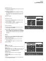
IPPV ventilation mode
IPPV = Intermittent Positive Pressure Ventilation
Volume-controlled ventilation with fixed mandatory minute
volume (MV), set with the tidal volume (VT), breathing
rate (Freq.) and the ratio of inspiration time to expiration
(TI:TE ).
Presetting the ventilation parameters for IPPV
Julian
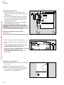
1 Press the »IPPV« hardkey; its LED flashes.
●
The six ventilation parameters for IPPV are displayed
on the screen with their default settings.
2 Press the softkey for the desired ventilation
parameter.
3 Set and confirm the ventilation parameter with the
rotary knob.
2
3
1
Display (example):
Standby
Julian
03.00
01-may-2000
Operation with
To Start IPPV: Confirm
Freshgas O2 + N2O
O2 %
L/min
50 4.00
40
MAN
SPONT
,
IPPV
or
PCV
!
Pmax
mbar
VT
mL
Freq.
1/min
TI:TE
TIP:TI
%
25 600 12 1:2.0 10
PEE
mbar
0
Operation
Selecting the ventilation mode
IPPV
Adjustment ranges and default settings on delivery
"Only for internal use by Draeger. Not applicable as Instructions for Use!"
Ventilation parameters
Adjustment
range
Default
setting
on delivery*
10 to 70
25
50 to 1400
600
6 to 60
12
2.0:1 to 1:2.0 in
increments of 0.1,
1:2.0 to 1:4.0, in
increments of 0.5
1 : 2.0
Insp. pause time :
Insp. time TIP : TI [%]
0 to 50
10
PEEP [mbar]
0 to 20
0
Pressure limit
Pmax [mbar]
Tidal volume VT
[mL]
Frequency Freq.
[1/min]
Insp/Exp ratio
TI : TE
For tidal volumes VT of less than 200 mL:
●
Use the paediatric hose set,
see "Ventilating children", page 49.
In IPPV ventilation mode, automatic system compliance
compensation takes place, and the applied tidal volume
therefore corresponds to the set volume.
Julian
Starting IPPV
1 Press the »IPPV« hardkey
2 and confirm with the rotary knob.
Display (example):
2
1
The preset ventilation parameters are displayed on the
screen.
The symbol
rotates in the softkey »L/min« to indicate
that fresh gas is flowing.
IPPV
Pleth
SpO2
If a change in ventilation parameters is required:
●
Press the corresponding softkey. Set and confirm the
ventilation parameter with the rotary knob.
etCO2
CO2
40
MV
O2
0
PAW
20
N2O
Iso.
Enf.
0
98
38
6.0
Freshgas O2+N2O
The default values can be set specifically for each hospital,
see page 82.
O2 %
L/min
50 4.00
Pmax
mbar
VT
mL
Freq.
1/min
freq
10
Fi
Fet
45
53
0.8
0.6
41
51
0.6
0.5
MAC (age: 36)
*
67
TI:TE
alarm
limits
auto set
limits
alarm
info
list
curves
config.
1.3
TIP:TI
PEEP
%
mbar
25 600 10 1:2.0 10
0
41
Operation
Selecting the ventilation mode
IPPV
Alarms effective in IPPV mode
"Only for internal use by Draeger. Not applicable as Instructions for Use!"
Alarm limits
In IPPV mode
Default setting
on delivery
SpO2
_
ON
ON
––
92
Pulse H
_
ON
ON
120
50
etCO2
_
ON
ON
50 mmHg
––
FiCO2
>
_
ON
5 mmHg
ON
ON
––
3.0
FiO2
_
ON
ON
––
20
Fi Hal.
_
ON
ON
1.5
––
Fi Iso.
_
ON
ON
2.3
––
Fi Enf.
_
ON
ON
3.4
––
Fi Des.
_
ON
ON
12.0
––
Fi Sev.
_
ON
ON
3.4
––
PAW
_
ON
ON
40
8
MV
Apnoea pressure
ON
Active after
15 seconds
Apnoea flow
ON
Active after
15 seconds
Apnoea CO2
ON
Active after
15 seconds
– – : The default setting on delivery is outside the
monitoring range and the corresponding alarm limit
is switched off.
To set the values of the alarm limits during operation see
page 60.
To set the default alarm limits see page 87.
42
Operation
Selecting the ventilation mode
PCV
PCV ventilation mode
"Only for internal use by Draeger. Not applicable as Instructions for Use!"
PCV = Pressure Controlled Ventilation
In pressure controlled ventilation mode, the applied tidal
volume depends on the ventilation parameters Pmax,
insp. Flow, insp. Time, PEEP and the lung compliance.
Changes in ventilation parameters or lung compliance
influence the tidal volume and the MV minute volume
must therefore be monitored constantly.
Presetting ventilation parameters for PCV
Julian
1 Press »PCV« its LED flashes.
●
The five ventilation parameters for PCV appear on the
screen with the default settings.
2 Press the softkey of the relevant ventilation parameter.
3 Set and confirm the ventilation parameter with the
rotary knob.
2
3
1
Display (example):
Standby
Julian
03.00
01-may-2000
Operation with
To Start PCV : Confirm
Freshgas O2 + N2O
O2 %
L/min
50 4.00
MAN
SPONT
,
IPPV
or
PCV
!
Pmax
Freq.
mbar
1/min
15
TI:TE
Insp.Flow
L/min
12 1:2.0 30
PEE
mbar
0
43
Operation
Selecting the ventilation mode
PCV
Adjustment ranges and default settings on delivery*
"Only for internal use by Draeger. Not applicable as Instructions for Use!"
Ventilation parameter
Pressure limit
Pmax [mbar]
Frequency Freq.
[1/min]
Insp./Exp. ratio
TI : TE
Insp. flow [L/min]
PEEP [mbar]
Adjustment
range
(PEEP+1)
to 70
6 to 60
Default setting
on delivery
15
2.0:1 to 1:2.0 in
increments of 0.1,
1:2.0 to 1:4.0, in
increments of 0.5
1 : 2.0
5 to 50 (75**)
0 to 20
30
0
12
When ventilating infants weighing less than 20 kg:
●
Use the paediatric hose set;
see page 49 "Ventilating children".
Starting PCV
Julian
1 Press »PCV«.
2 Confirm by pressing the rotary knob.
2
1
Display (example):
IPPV
The preset ventilation parameters appear on the screen.
Pleth
Fresh gas flows, as indicated by the rotating symbol
in the softkey »L/min«.
If a change in ventilation parameters is required:
●
Press the relevant softkey. Set and confirm the
ventilation parameter with the rotary knob.
SpO2
etCO2
CO2
40
MV
0
O2
PAW
20
N2O
Iso.
Enf.
0
98
67
38
6.0
10
Fi
Fet
45
53
0.8
0.6
41
51
0.6
0.5
MAC (age: 36)
*
The default settings can be set specifically for each hospital,
see page 82.
** Can be set by DrägerService.
44
Freshgas O2+N2O
O2 %
L/min
50 4.00
Pinsp
mbar
VT
mL
Freq.
1/min
freq
TI:TE
alarm
limits
auto set
limits
alarm
info
list
curves
config.
1.3
TIP:TI
PEEP
%
mbar
25 600 10 1:2.0 10
0
Operation
Selecting the ventilation mode
PCV
Alarms effective in PCV mode
"Only for internal use by Draeger. Not applicable as Instructions for Use!"
Alarm limits
In PCV mode
Default setting
on delivery
SpO2
_
ON
ON
––
92
Pulse H
_
ON
ON
120
50
etCO2
_
ON
ON
50 mmHg
––
FiCO2
>
ON
5 mmHg
MV
_
ON
ON
––
3.0
FiO2
_
ON
ON
––
20
Fi Hal.
_
ON
ON
1.5
––
Fi Iso.
_
ON
ON
2.3
––
Fi Enf.
_
ON
ON
3.4
––
Fi Des.
_
ON
ON
12.0
––
Fi Sev.
_
ON
ON
3.4
––
PAW
_
ON
ON
40
8
Apnoea pressure
ON
Active after
15 seconds
Apnoea flow
ON
Active after
15 seconds
Apnoea CO2
ON
Active after
15 seconds
– – : The default setting on delivery is outside the
monitoring range and the corresponding alarm limit
is switched off.
To set the values of the alarm limits during operation see
page 60.
To set the default alarm limits see page 87.
45
Operation
Setting the Vapor unit
Aspirating secretion
Setting the Vapor unit
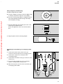
1 Lock the unused Vapor unit
= push lever fully in the direction of the unused Vapor
(example: left-hand Vapor locked).
0
If the handwheel is in the »T« position:
1
0
"Only for internal use by Draeger. Not applicable as Instructions for Use!"
2 Press 0 button and engage handwheel at 0.
Wait 5 seconds for pressure compensation.
3
2
2 Press 0 button and
3 Turn handwheel anti-clockwise to required
anaesthetic agent concentration.
Aspirating secretion
●
Swing the bottles forwards.
D
1 Set the switch to I.
Julian
2 Seal the "fingertip" or kink the suction hose and
3 Set the appropriate suction pressure for the patient
with the rotary knob »Vac.« and
4 check on the pressure gauge.
4
Observe the hygiene regulations of the hospital!
1
2
After aspirating
●
Rinse the suction hose with the water purifier.
1 Set the switch to 0.
46
3
Operation
Changing patients
Changing soda lime
Changing patients
To switch Julian to standby:
●
Press the Standby key E and confirm with the
rotary knob.
Standby
"Only for internal use by Draeger. Not applicable as Instructions for Use!"
The functions of the workstation are switched off.
The set alarm limits are cancelled and the default alarm
settings are valid again.
Julian
leakage
test
03.00
01-may-2000
The default settings are loaded for dosing anaesthetic
gas and for the ventilation parameters.
delete
trend
config.
If the ventilation hoses have been changed:
●
Perform a leakage test, page 48.
Operation with
MAN
SPONT
,
IPPV
or
PCV
Freshgas O2+N2O
O2 %
L/min
50 4.00
Changing soda lime
– If the soda lime in the absorber has turned violet.
1
– If the inspiratory CO2 concentration FiCO2 equals
5 mmHg or more.
●
Press the Standby key E and confirm by pressing
the rotary knob.
1 Raise the writing top.
2 Pull the catch and draw out the breathing system at
the same time.
2
3 Turn the absorber counterclockwise and pull it out
downwards.
●
Drain the used soda lime and dispose of with
domestic waste.
●
Fill the absorber with fresh soda lime up to the MAX
mark.
●
Fit the absorber to the breathing system from below
and turn it clockwise as far as it will go.
●
Push the breathing system inwards until it clicks into
place.
●
Fold down the writing top.
MAX
3
47
Operation
Leakage test
Leakage test
Must not be performed when a patient is connected to
the workstation!
– When the soda lime has been changed
or
"Only for internal use by Draeger. Not applicable as Instructions for Use!"
– when the breathing hoses have been changed.
– if the Vapor has been changed or topped up.
●
test with the handwheel set to »0« and
●
test with the handwheel set to less than 0.2% by vol.
●
After the leakage test, turn handwheel to »0«.
1 Close the Y-piece = place firmly on the cone.
2
2 Ensure that the sample line is connected to the
Y-piece and to the water trap at the back of the
workstation.
●
2
Press the softkey »leakage« in standby mode.
1
Julian performs the leakage test for IPPV/PCV and
determines the volume correction for system compliance.
Duration approx. 30 seconds.
The breathing bag and its hose are not included in the
test.
Display:
Leakage test
After the test has been successfully completed, the clock
symbol disappears and Julian displays the values for
leakage and system compliance for a few seconds.
The results of the leakage test are continually displayed
on the data screen.
To return to the standby screen:
●
48
Press the rotary knob.
Systemcompliance
Leakage
Please wait.
cancel
test
Operation
Ventilating children
Ventilating children
For tidal volumes VT of less than 200 mL:
●
Use paediatric hoses.
Connecting the breathing hoses
"Only for internal use by Draeger. Not applicable as Instructions for Use!"
1 Use Y-piece with connection for sample line.
●
The inspiratory and expiratory
microbial filter 654 St should not be used – this
reduces the system compliance.
1
3
2
2 Connect 0.5 L breathing bag with socket to the
breathing hose with the large connection sleeves.
Slip the breathing hose over the angled socket.
Hang the 0.5 L breathing bag onto the hook.
3 Slip the breathing hoses with the large sleeves onto
the inspiratory and expiratory sockets and connect the
small sleeves to the Y-piece.
4 Connect the sample line to the Y-piece and water
trap.
●
4
Set the sample rate to 200 mL/min, page 84.
If the measured gas is not recirculated:
●
Increase the tidal volume VT in accordance with the
sample rate.
Volumeter function:
●
Select »Child« scale, page 67.
To determine system compliance and leakage:
5 Firmly connect the Y-piece to the cone.
●
Determine the system compliance and leakage,
see „Leakage test“ on page 48.
Set a correspondingly higher tidal volume VT in
accordance with the airway pressure PAW.
●
Use PCV or IPPV ventilation mode.
5
49
Operation
Using non-rebreathing systems
Using non-rebreathing systems
"Only for internal use by Draeger. Not applicable as Instructions for Use!"
Example: Bain system
●
Prepare the Bain system in accordance with the
separate Instructions for Use.
●
Remove sample line from Y-piece, as otherwise Julian
activates a PAW NEGATIVE alarm.
2
3
1
For the specified monitoring of O2, CO2 and anaesthetic
agents:
1 Screw the sample line to the Luer lock connection of
the mask manifold pipe and to the water trap on the
back of the workstation.
For mask pipes without sample line connector:
●
Place a T-piece with filter between the mask pipe and
fresh gas connection port.
or:
●
where applicable, use the Luer lock connection of a
filter.
2 Connect the fresh gas hose of the Bain system to the
fresh gas outlet.
3 Connect the anaesthetic gas scavenging system AGS
to the Bain system.
●
Note the Instructions for Use of the Bain system.
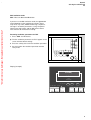
MAN/SPONT
Display (example):
Pleth
SpO2
In MAN/SPONT ventilation mode:
●
Press the softkey »Fresh gas internal / external«,
select »Fresh gas external« and confirm by pressing
the rotary knob.
etCO2
CO2
40
MV
0
O2
VT
0.65
--
0
0.5
Volumeter --s
0
Start volumeter: Confirm
Freshgas O2 + N2O
O2 %
L/min
50 4.00
50
1
N2O
Iso.
Enf.
5
10
!
freshgas
internal
external
98
38
5.2
67
FiCO2
_
freq
8
Fi
Fet
45
53
0.8
0.6
41
51
0.6
0.5
MAC (age: 36)
1.3
alarm
limits
CO2-al.
on/off
alarm
info
list
curves
config.
Operation
Using non-rebreathing systems
Display (example):
FRESHGAS EXTERNAL
Pleth
The airway pressure (PAW), minute volume (MV) and
frequency are not measured.
●
Set the fresh gas flow. The fresh gas supply must be
at least twice the minute volume in order to prevent
rebreathing.
SpO2
etCO2
CO2
40
MV
"Only for internal use by Draeger. Not applicable as Instructions for Use!"
0
O2
Certain alarms are automatically switched off in order to
avoid artefacts.
The inactive alarm limits are highlighted by the grey
background in the following table.
Alarm limits
In external fresh
gas mode
Default setting on
delivery
N2O
Iso.
Enf.
_
ON
ON
––
92
Pulse H
_
ON
ON
120
50
etCO2
_
*
*
FiCO2
>
*
50 mmHg
––
––
MV
_
OFF
OFF
––
––
FiO2
_
*
ON
––
20
Fi Hal.
_
ON
OFF
1,5
––
Fi Iso.
_
ON
OFF
2,3
––
Fi Enf.
_
ON
OFF
3,4
––
Fi Des.
_
ON
OFF
12,0
––
Fi Sev.
_
ON
OFF
3,4
––
PAW
_
ON
OFF
40
––
Apnoe Druck
OFF
Apnoe Volumen
OFF
Apnoe CO2
ON
*
38
--
67
_
alarm
limit
freq
CO2 al.
on/off
--
alarm
info
FiCO2
Fi
Fet
45
53
0.8
0.6
41
51
0.6
0.5
MAC (age: 36)
list
curves
config.
1.3
Freshgas O2 + N2O
freshgas
O2 %
L/min
50 6.00
SpO2
98
internal
external
The etCO2 _, FiCO2 > and FiO2 > alarms can
be configured »ON« or »OFF« in standby mode for the
transition from MAN/SPONT. When the alarm limits
are set to »ON«, the value is transferred from automatic
ventilation mode.
51
Operation
Using non-rebreathing systems
In the event of a power failure
Switch off the external fresh gas output:
●
Press the softkey »Fresh gas internal / external«,
select »Fresh gas internal« and confirm by pressing
the rotary knob:
Julian switches over to MAN/SPONT ventilation mode
or
"Only for internal use by Draeger. Not applicable as Instructions for Use!"
●
Press the »IPPV« or »PCV« key and confirm with the
rotary knob.
Julian then switches over directly to controlled ventilation
via the original rebreathing system.
When changing from the external non-rebreathing system
to the rebreathing system of the Julian:
●
Reconnect the sample line to the Y-piece.
In the event of a power failure
IPPV
Julian automatically switches over to the integrated
uninterruptible power supply (UPS).
If the battery is charged, operation will be maintained for
an average of 30 minutes.
The message
POWER FAIL !
Pleth
SpO2
etCO2
CO2
40
MV
POWER FAIL!
0
appears on the screen
together with the remaining available battery capacity in
percent.
Example:
J
95 %
O2
PAW
20
N2O
Iso.
Enf.
0
98
38
6.0
O2 %
L/min
50 1.00
Pmax
mbar
VT
mL
25
600
Freq.
1/min
freq
10
Fi
Fet
45
53
0.8
0.6
41
51
0.6
0.5
MAC (age: 36)
Freshgas O2+N2O
67
TI:TE
Version with rotary knob for O2 emergency metering:
Set rotary knob »Safety-O2« for O2 emergency
metering to the desired O2 flow.
Range 0 to 12 L/min.
This O2 flow flows through the Vapor unit.
●
●
Check Vapor unit setting.
●
Ventilate patient manually!
* Can be set to 4 L/min by DrägerService
52
auto set
limits
alarm
info
list
curves
config.
TIP:TI
PEEP
%
mbar
10 1:2.0 10
In the event of a power failure if the battery is discharged,
Julian switches over automatically to MAN/SPONT
ventilation mode. The fresh gas mixer is deactivated.
D
alarm
limits
1.3
If the battery is almost completely discharged, the
message BATTERY LOW !!! appears on the screen.
Version without rotary knob for O2 emergency
metering:
Julian automatically delivers an O2 flow of 8 L/min*.
This O2 flow bypasses the Vapor unit, and so the patient
no longer receives any anaesthetic agent.
J
95 %
Julian
0
Operation
In the event of a gas failure
System fault
In the Event of a Major Hardware Fault
In the event of a gas failure
"Only for internal use by Draeger. Not applicable as Instructions for Use!"
Julian activates an alarm if the O2 or AIR or N2O supply
fails.
●
Open the valve on the corresponding backup gas
cylinder on the rear of the workstation.
●
Reconnect the central gas supply.
If there is no backup supply of gas available, Julian
replaces the set gas mixture with AIR or O2:
N2O
O2
Julian delivers 100 % AIR if the O2 supply fails.
Julian delivers 100 % O2 if the N2O supply fails.
Julian delivers 100 % O2 if the AIR supply fails.
The amount of fresh gas flow (L/min) remains constant.
Fresh gas metering is still possible even in the event of
failure of one of the gases. For example, if the N2O
supply fails, AIR can be selected as the carrier gas.
System fault
MAN/SPONT
such as implausible measured values, the message:
VENT INOP!!!
will be displayed.
Julian first performs a warm start.
Display (example):
VENT INOP !!!
98 67 alarm
SpO
limits
Pleth
2
MV
0
0.04
O2
0
0.5
1
Volumeter --s
If the warm start is successful, Julian returns to the
previous ventilation mode.
2.7
0
10
Fet
41
51
0.6
0.5
MAC (age: 36)
alarm
info
list
curves
config.
1.3
!
MAN/SPONT
SYSTEM FAULT !!!
98 67 alarm
SpO
limits
Pleth
2
et
CO2
CO2
40
MV
Display (example):
0
O2
VT
In the event of total system failure including the screen,
an alarm will sound for about 30 seconds.
In such cases Julian switches to MAN/SPONT ventilation
mode.
Fi
45
53
0.8
0.6
CO2-al.
on/off
MAN/SPONT ventilation mode is activated. Only manual ventilation is possible.
Mechanical ventilation not available for about 30 sec.
Internal system fault.
In the event of a Major Hardware Fault
The audio alarm can be switched off by acknowledging
via the rotary knob.
N2O
Iso.
Enf.
5
Start volumeter: Confirm
such as the failure of the fresh gas mixer, the message:
SYSTEM FAULT!!!
will be displayed.
38 _
5.2
8
40
VT
If the warm start is unsuccessful, Julian behaves as
described under "In the event of a major hardware fault".
FiCO2 Freq
et
CO2
CO2
0.04
0
0.5
1
Volumeter --s
2.7
0
Switch off alarm:
5
N2O
Iso.
Enf.
10
FiCO2 Freq
38 _
5.2
8
Fi
Fet
45
53
0.8
0.6
41
51
0.6
0.5
MAC (age: 36)
CO2-al.
on/off
alarm
info
list
curves
config.
1.3
Confirm!
MAN/SPONT ventilation mode is activated. Only manual ventilation is possible.
Fresh gas =100% O2 with fixed dosage >4 L/min.
Equipment not dosing anaesthetic agent. Internal system fault has occurred.
Mechanical ventilation not possible.
53
End of Operation
Version without rotary knob for O2 emergency
metering:
Julian automatically delivers an O2 flow of 8 L/min*.
This O2 flow bypasses the Vapor unit, and so the patient
no longer receives any anaesthetic agent.
Version with rotary knob for O2 emergency metering:
Set rotary knob for O2 emergency metering to the
desired O2 flow.
Range 0 to 12 L/min.
This O2 flow flows through the Vapor unit.
"Only for internal use by Draeger. Not applicable as Instructions for Use!"
●
●
Check the Vapor unit setting.
●
Ventilate the patient manually!
End of Operation
To switch Julian to Standby:
●
Press the standby key E and confirm by pressing
the rotary knob.
The workstation is now on standby.
The fresh gas flow is switched off.
Manual ventilation is not possible!
The following default values are activated in standby
mode:
Fresh gas default values
Ventilation parameters
Alarm limits
To switch Julian off:
●
Press the power switch »
« down completely.
Julian is fitted with a switch-off delay. When the power
switch is pressed, an audible signal sounds and the
message
"System can be switched on again without loss of
data. System is being closed down and switched off"
appears for 10 seconds.
Within this 10-second period Julian can be restarted
immediately by pressing the power switch again.
The switch-off delay is not active during the self-test.
●
Remove the gas supply probes from the wall sockets.
●
Leave Julian plugged into the power supply in order to
charge the uninterruptible power supply (UPS).
●
In case of mains power supply failure, the power
switch should always be switched off. Starting up
the workstation with the power switch on and the
UPS discharged leads to emergency dosage.
To switch off the anaesthetic gas scavenging system
AGS:
●
Pull back the black sleeve on the connector of the
suction hose to release the connector.
* Can be set to 4 L/min by DrägerService
54
Monitoring
Contents
Monitoring
Contents
"Only for internal use by Draeger. Not applicable as Instructions for Use!"
Selecting the standard screen................................................................56
Selecting the data screen.......................................................................57
Selecting the trend screen..................................................................... 58
Zoom function.......................................................................................... 59
To delete the trend memory...................................................................... 59
Alarms..................................................................................................... 60
Displaying and setting alarm limits............................................................ 60
Adapting limits – AutoSet......................................................................... 62
If an alarm occurs................................................................................... 63
Alarm info................................................................................................64
CO2 alarms on /off................................................................................. 64
List display.............................................................................................. 65
Delete list................................................................................................. 65
Selecting curves..................................................................................... 66
Using the volumeter function................................................................. 67
Starting the volumeter...............................................................................67
Configuring in operation......................................................................... 68
Setting the monitoring functions................................................................69
Setting the pulse tone...............................................................................69
Setting the alarm sound............................................................................69
Selecting the scale................................................................................... 69
Setting the measuring parameters............................................................ 70
Record..................................................................................................... 71
Time.........................................................................................................71
Manual calibration...................................................................................72
Activating monitor defaults........................................................................72
Selecting alarms.......................................................................................72
Default..................................................................................................... 72
Alarm mode for the heart-lung machine HLM............................................ 73
MAC configuration.................................................................................. 74
Anaesthetic agent identification and display.............................................. 74
Calculating the MAC values......................................................................74
Displaying MAC....................................................................................... 75
SpO2 Measurement (optional)................................................................. 76
Sensor selection.......................................................................................76
C-lock-ECG synchronization (optional)..................................................... 77
Tips to prevent artefacts........................................................................... 78
Applying the Durasensor DS-100 A.......................................................... 79
Airway temperature measurement (optional)..........................................80
55
Monitoring
Selecting the standard screen
Monitoring
Selecting the standard screen
"Only for internal use by Draeger. Not applicable as Instructions for Use!"
The standard screen is automatically displayed on the
screen whenever a ventilation mode is selected
(MAN/SPONT or IPPV or PCV). This page can always
be selected during operation:
Julian
1 Press the Q key
or
2
1
2 Press the S key several times.
Display (example):
IPPV
Pleth
The most important parameters are grouped together on
the right-hand side of the screen.
Three curves are displayed on the left-hand side
(to select other curves, see page 66).
SpO2
etCO2
CO2
40
MV
O2
0
Measured values shown in grey
Calibration is performed automatically by Julian. The
measured values are shown in grey until sufficient data
are available and until the sensors have reached their
operating temperature.
In this way, Julian indicates that the accuracy of these
data is still reduced in comparison with the "Technical
data".
For maximum accuracy the sensors can be calibrated
manually – see page 72.
When measuring CO2, anaesthetic agent and N2O, their
numerical values are shown in grey during the warm-up
phase whenever the workstation is switched on.
Because the gas measuring module switches off
internally in standby mode, calibration is carried out each
time the unit is switched on. This is indicated by »Cal« in
the measured value window.
The display CAL appears instead of the numerical value
during automatic calibration of the O2 sensor (every
24 hours).
The flow sensor is automatically calibrated as soon as a
CO2 signal is detected by the gas measuring system.
Julian takes account of the relevant gas mixture when
calculating the volumetric concentrations.
56
PAW
20
N2O
Iso.
Enf.
0
98
38
6.0
O2 %
L/min
50 4.00
Pmax
mbar
VT
mL
Freq.
1/min
freq
10
Fi
Fet
45
53
0.8
0.6
41
51
0.6
0.5
MAC (age: 36)
Freshgas O2+N2O
67
TI:TE
alarm
limits
auto set
limits
alarm
info
list
curves
config.
1.3
TIP:TI
PEEP
%
mbar
25 600 10 1:2.0 10
0
Monitoring
Selecting the data screen
Selecting the data screen
● Press the S key several times until the data page
appears.
IPPV
PAW
Display (example):
plat.
"Only for internal use by Draeger. Not applicable as Instructions for Use!"
40
All numerical values are displayed on the data screen
with their units of measure. The bar display on the left of
the screen shows the change in airway pressure PAW
over time. The lines cutting across the bar graph mark
the upper and lower alarm limits. To set the alarm limits
for PAW, see page 60.
PEEP
mean
compliance
27
20
5
15
65
mbar
6.0
VT
0.60
freq
10
AW-temp.
34
MV
SpO2
%
98
mbar
67
1/min
Fi
Fet
0
40
58
0.8
0.4
MAC (age: 36)
36
33
56
0.6
0.5
1.3
1/min
15. Dec. 99
12 : 00
°C
sys. comp. 6.40 mL/mbar
leckage
10 mL/min
mbar
CO2
mmHg
mbar
O2 %
mL/mbar
N2O %
20
0
The system compliance (Sys.-Compl.) and leakage are
displayed in the right-hand field, together with the time of
the last test.
peak
Iso. %
L/min
Enf. %
L
alarm
limits
auto set
limits
alarm
info
list
config.
01-10
8 : 00
Freshgas O2 + N2O
Pmax
O2 %
L/min
50 1.00
mbar
VT
mL
Freq.
1/min
TI:TE
TIP:TI
PEEP
%
mbar
25 600 10 1:2.0 10
0
57
Monitoring
Selecting the trend screen
Selecting the trend screen
Displays the measured values over time since the start of
measurement.
"Only for internal use by Draeger. Not applicable as Instructions for Use!"
Maximum storable time: 8 hours.
The following display combinations can be selected:
– CO2/MV
– AGas/N2O
– O2/compliance*
– SpO2/pulse rate
●
Press the S key several times until the trend screen
appears.
MV and compliance trends are scaled in accordance with
the setting in the configuration menu for adults or
children.
MV trend scale:
0 to 3 L/min for children
0 to 15 L/min for adults
Compliance trend scale:
0 to 20 mL/mbar for children
0 to 100 mL/mbar for adults
Display (example):
Trend CO2 and MV
IPPV
PAW
60
SpO2
40
0
11:00
Press the appropriate softkey:
»AGas N2O«
or
»O2 compl.«
or
»SpO2 pulse«
20
0
98
67
30
etCO2
Selecting other display combinations
●
CO2
12:00
13:00
MV
MV
15
O2
10
N2O
Iso.
38
6.0
AGas
N 2O
Fi
Fet
45
53
0.8
0.6
41
51
0.6
0.5
O2
compl.
Enf.
0
MAC (age: 36)
Zoom in: Press
!
CO2
MV
10
5
Select zoom area: Turn
freq
alarm
limits
SpO2
pulse
full
trend
1.3
!
Freshgas O2 + N2O
The softkey disappears if a measuring function is not
available.
____________
*
58
Lung properties can be monitored continuously with the compliance
trend display so that ventilation can be adjusted accordingly.
Patient compliance is not measured in MAN/SPONT ventilation
mode.
O2 %
L/min
50 1.00
Pmax
VT
Freq.
mbar
mL
1/min
TI:TE
TIP:TI
PEEP
%
mbar
25 600 10 1:2.0 10
0
Monitoring
Selecting the trend screen
Zoom function
The trend display can be magnified with the zoom
function after half-an-hour of operation.
IPPV
PAW
60
CO2
SpO2
40
etCO2
0
Turn the rotary knob = the dashed frames move.
11:00
"Only for internal use by Draeger. Not applicable as Instructions for Use!"
20
To enlarge the selected area to the full width of the
display:
0
●
Press the rotary knob.
A new dashed frame appears after a corresponding
period of operation and can also be enlarged.
●
12:00
MV
13:00
MV
15
O2
10
N2O
Iso.
Enf.
5
38
6.0
freq
CO2
MV
AGas
N 2O
Fi
Fet
45
53
0.8
0.6
41
51
0.6
0.5
O2
compl.
Zoom in: Press
!
alarm
limits
10
SpO2
pulse
full
trend
1.3
MAC (age: 36)
0
Select zoom area: Turn
!
Freshgas O2 + N2O
O2 %
To return to the overall trend:
67
30
To select the range:
●
98
L/min
50 1.00
Pmax
VT
Freq.
mbar
mL
1/min
TI:TE
TIP:TI
PEEP
%
mbar
25 600 10 1:2.0 10
0
Press the softkey »full trend« and the complete trend
is displayed again.
If the trend data are insufficient this softkey has no
function.
To delete the trend memory
Only possible in standby mode.
The trend memory and list are deleted together!
Standby
In standby mode:
●
Press the softkey »delete trend«.
Julian
leakage
test
03.00
01-may-2000
delete
trend
config.
Operation with
MAN
SPONT
,
IPPV
or
PCV
Freshgas O2+N2O
O2 %
L/min
50 4.00
The system asks you to confirm that the trend is really to
be deleted.
To delete:
●
Standby
Press the softkey »delete«.
The stored trend for the anaesthetic gas concentration is
deleted automatically when a new anaesthetic gas is
selected.
Julian
delete
03.00
01-may-2000
do not
delete
config.
Operation with
MAN
SPONT
,
IPPV
or
PCV
Freshgas O2+N2O
O2 %
L/min
50 4.00
59
Monitoring
Alarms
Alarms
Displaying and setting alarm limits
"Only for internal use by Draeger. Not applicable as Instructions for Use!"
Alarms can be displayed and set from all three basic
screens (standard, data and trend screen) during
operation.
The default alarm limits for the ventilation mode are
activated automatically when changing from standby to a
ventilation mode.
These default alarm limits can be used unchanged or they
can be set individually for the patient.
The individual settings are deleted on changing from
ventilation mode to standby and the default alarm limits
are reactivated.
To call up alarm limits:
●
Press the softkey »alarm limits«.
IPPV
Display (example):
Pleth
The measured values and their alarm limits are shown on
the right-hand side.
The curves with the alarm limits represented by dashed
lines are shown on the left.
SpO2
CO2
etCO2
40
MV
0
FiO2
PAW
20
FiHal.
-95
98
67
38
6.0
29
0.8
120
50
42
30
-3.0
-20
1.0
0.0
0
auto set
limits
alarm
info
list
curves
config.
40
8
PAW
Select limit value: Turn and confirm
alarm
limits
!
Freshgas O2 + N2O
O2 %
L/min
50 1.00
Example etCO2:
The upper alarm limit (42 mmHg) and the lower alarm
limit (30 mmHg) are shown alongside the measured value
(38 mmHg).
A deactivated alarm limit is indicated by two dashes (– –).
To set an alarm limit:
●
Place the cursor bar on the alarm limit by turning the
rotary knob and press to confirm.
The alarm limit is highlighted.
●
Set the new value by turning the rotary knob and
press to confirm.
The new alarm limit is now effective. The cursor bar
returns to the z symbol.
60
etCO2
Pmax
VT
Freq.
mbar
mL
1/min
TI:TE
TIP:TI
PEEP
%
mbar
25 600 10 1:2.0 10
38
42
30
0
Monitoring
Alarms
Adjustment range of the alarm limits
"Only for internal use by Draeger. Not applicable as Instructions for Use!"
Alarm limit
Adjustment range
SpO2
[%]
_
51 to 100
50 to 99
Pulse H
[1/min]
_
21 to 250
20 to 249
etCO2
[mmHg]
_
1 to 75
0 to 74
FiCO2
[mmHg]
_
0 to 10
––
MV
[L/min]
_
0,1 to 39
0 to 38,9
FiO2
[Vol.%]
_
19 to 100
18 to 99
Fi Hal.
[Vol.%]
_
0,1 to 7
0 to 6,9
Fi Iso.
[Vol.%]
_
0,1 to 7
0 to 6,9
Fi Enf.
[Vol.%]
_
0,1 to 7
0 to 6,9
Fi Des.
[Vol.%]
_
0,1 to 21,9
0 to 21,8
Fi Sev.
[Vol.%]
_
0,1 to 9,9
0 to 9,8
PAW
[mbar]
_
5 to 98
4 to 35
To quit the alarm limits menu:
●
●
Press the rotary knob
or
Press the Q key.
61
Monitoring
Alarms
Adapting limits – AutoSet
When the ventilation settings have been made, Julian can
automatically adapt the alarm limits for the minute volume
(MV) and airway pressure (PAW) to the current
ventilation settings in IPPV mode.
"Only for internal use by Draeger. Not applicable as Instructions for Use!"
●
Press the softkey »auto set limits«. The alarm limits
menu opens automatically.
The alarm limits for MV and PAW are adapted.
At the same time, an advisory message is displayed:
"MV and PAW limits have been automatically
adapted". The menu closes again automatically after
5 seconds.
The new alarm limits for the set MV are calculated by
Julian as follows:
MV
[L/min]
Upper alarm limit
Lower alarm limit
Measured MV · 1,4
At least 2,0
Measured MV · 0,6
At least 0,5
Julian calculates the new PAW alarm limits by determining
PEAK, PPlateau and PEEP by two different methods and
selecting the higher value as the "measured value".
Method 1:
The mean of the last 4 measured breaths. If fewer
measured values are available, these are used as the
basis of determination.
Method 2:
The measured value of the last breath.
Julian sets the upper alarm limit for PAW to the absolute
higher determined measured value of
– PEAK + 5 mbar or
– PPlateau + 10 mbar, but at not less than 10 mbar
in IPPV/PCV.
Julian sets the lower alarm limit for PAW from the
determined measured values to
– PEEP + 0,6 · (PPlateau – PEEP),
and not less than 4 mbar in IPPV/PCV.
To reset individual alarm limits for MV and PAW:
●
See "Displaying and setting alarm limits"
on page 60.
To reuse all default alarm limits:
●
62
See "Activating monitor defaults" on page 72.
Monitoring
If an alarm occurs
If an alarm occurs
Alarm messages are assigned to three priority classes
by Julian, depending on their urgency, and identified by
exclamation marks:
"Only for internal use by Draeger. Not applicable as Instructions for Use!"
Warning !!! = message with top priority
A warning message requires immediate action.
Caution !! = message with medium priority
A caution message requires prompt action.
Advisory ! = message with lowest priority
Least-priority messages can also be displayed by
symbols. An advisory message requires to be noted and
action taken if necessary.
If several alarms occur simultaneously, Julian displays the
alarm with the highest priority. The others are not
displayed.
All warning, caution and advisory messages that have
been emitted can be displayed by pressing the
»alarm Info« softkey.
Each time an alarm message is displayed, the alarm lamp
either flashes or lights up continuously and an audible
tone sequence is emitted to indicate the alarm priority
class:
Warning:
1 Red lamp flashes, accompanied by a continuous tone.
Caution:
1 Yellow lamp flashes, accompanied by an intermittent
tone every 30 seconds.
Julian
1
2
Advisory:
1 Yellow lamp lights up continuously, accompanied by a
single tone.
The alarm tone can be suppressed for two minutes:
2 Press the G key and its yellow LED lights up.
To reactivate the alarm tone:
2 Press the G key and its yellow LED goes out.
A list of alarm messages can be found on page 122,
"Message – Cause – Remedy".
63
Monitoring
CO 2 alarms on/off
Alarm info
Alarm info
IPPV
This function is used to list all active alarms / warnings in
order of priority.
●
FIO2
ETCO2
Pleth
Press and hold the softkey »alarm info«.
!!!
!!
alarm
limits
auto set
limits
CO2
alarm
info
40
Display (example):
"Only for internal use by Draeger. Not applicable as Instructions for Use!"
list
Active alarms:
FIO2 < !!!
0
PAW
20
Active warning:
ETCO2 < !!
curves
config.
0
Freshgas O2 + N2O
Pmax
O2 %
L/min
50 1.00
The display only remains visible as long as the softkey is
pressed.
mbar
VT
mL
25
600
Freq.
TI:TE
TIP:TI
PEEP
%
mbar
1/min
10 1:2.0 10
0
CO2 alarms on /off
The alarm limits for FiCO2, etCO2 and CO2 apnoea
monitoring can be switched off with the softkey
»CO2-al. on/off« in MAN/SPONT mode.
In this case, the symbol CO2 gappears alongside the
measured end-expiratory CO2 concentration.
The CO2 alarm limits are reactivated by pressing the
softkey again. The deactivated CO2 alarm limits are
reactivated automatically when changing to a different
ventilation mode.
The CO2 alarm limits can also be activated and
deactivated under "Alarm limits" in the configuration
screen in all ventilation modes, see page 72.
The etCO2 _ and FiCO2 > alarms can be configured
»ON« or »OFF« in standby mode for the transition from
MAN/SPONT. When the alarm limits are set to »ON«, the
value is transferred from automatic ventilation mode.
National and European standards require a minimum
monitoring with alarm function. These standards may not
be met if the alarm function of the etCO2 monitoring
parameter is deactivated.
64
MAN/SPONT
Pleth
SpO2
etCO2
CO2
40
MV
0
O2
VT
N2O
0.35 Volumeter
-0
0
Start Volumeter: Confirm
0.5
1
-- s
5
Freshgas O2 + N2O
O2 %
L/min
50 4.00
Enf.
10
!
freshgas
internal
external
Iso.
98
38
5.2
67
CO2
g
freq
8
Fi
Fet
45
53
0.8
0.6
41
51
0.6
0.5
MAC (age: 36)
1.3
alarm
limits
CO2-al.
off / on
alarm
info
list
curves
config.
Monitoring
List display
List display
Record of measured values, alarms and ventilation
modes to facilitate compilation of the anaesthetic record.
The control criteria for entries can be configured, see
"Record" on page 71.
●
Press the softkey »list«.
"Only for internal use by Draeger. Not applicable as Instructions for Use!"
Display (example):
IPPV
next page
PAW
time
alarm
12:13
FI HAL
12:15
FI O2
HR/Puls NiBP/mmHg
Sys/M/Dia
40
"Open" the previous page:
12:20
●
Select »previous page« by turning the rotary knob
and press to confirm.
!!!
!!!
previous page
SpO2 etCO2 MV
O2
Fi/Fet
AGas
Fi/Fet
PAW
Peak/Peep
65
99
40
6.0
30/26
1.6/0.6
33/10
65
98
38
5.9
25/20
0.8/0.7
30/10
66
99
40
6.1
30/26
0.8/0.7
30/10
20
"Open" the next page:
●
Select »next page« by turning the rotary knob and
press to confirm.
0
Freshgas O2 + N2O
Return to the standard page:
●
O2 %
L/min
50 1.00
Pmax
VT
Freq.
mbar
mL
1/min
TI:TE
TIP:TI
PEEP
%
mbar
25 600 10 1:2.0 10
0
Place cursor on the zsymbol by turning the rotary
knob and press to confirm.
or
●
Press the Q key.
Delete list
The list and trend memory are deleted together!
Only possible in standby!
Standby
In standby:
●
Julian
Press the softkey »delete trend«.
leakage
test
03.00
01-may-2000
delete
trend
config.
Delete trends and list:
●
Press the softkey »delete«.
Operation with
MAN
SPONT
,
IPPV
or
PCV
Freshgas O2+N2O
O2 %
L/min
50 4.00
65
Monitoring
Selecting curves
Selecting curves
"Only for internal use by Draeger. Not applicable as Instructions for Use!"
Only possible from the standard screen!
Three curves can be selected and positioned for the
momentary ventilation mode in this menu.
The following curves can be selected:
CO2
Curve of CO2 concentration at the Y-piece
PAW
Airway pressure
Pressures
Digital indication of the measured value for
PPEAK, PPlateau, PMEAN and PEEP
Flow
Expiration flow
Pleth
The plethysmogram derived from SpO2
measurement (optional)
Volumeter
A display mode showing the minute volume
and tidal volume VT as bar graphs
O2
Curve of O2 concentration at the Y-piece
AGas
Curve of anaesthetic agent concentration at
the Y-piece
FG/volu
Volumeter in combination with bar display
of fresh gas flow in L/min for O2 and N2O
or AIR (virtual flow tubes)
FG/press
Pressures in combination with bar display
of fresh gas flow in L/min for O2 and N2O
or AIR (virtual flow tubes)
blank
Blank field
IPPV
Pleth
SpO2
et
CO2
●
Press the softkey »curves«.
Pleth
Flow
Display (example):
PAW
The names of the curves in each curve field are displayed
together with the choice of possible parameters. The
current curves are highlighted by a grey background.
In the example, the PAW curve is to be replaced by the
volumeter display.
Turn the rotary knob to select the required
parameter (»volumeter« ) and press to confirm.
The cursor jumps to the
menu.
●
O2
AGas
FG/volu
MV
FG/press
O2
blank
N2O
Iso.
Enf.
To select curve position:
38
6.0
Freq
Fi
Fet
45
53
0.8
0.6
41
51
0.6
0.5
alarm
info
list
curves
config.
1.3
Freshgas O2 + N2O
L/min
50 1.00
Pmax
VT
Freq.
mbar
mL
1/min
25 600
TI:TE
TIP:TI
PEEP
%
mbar
10 1:2.0 10
0
IPPV
Pleth
Select the desired position with the rotary knob and
press to confirm.
SpO2
et
CO2
Pleth
Flow
Volumeter
To return to the standard page:
CO2
PAW
Pressures
Flow
Pleth
Volumeter
O2
AGas
FG/volu
MV
FG/press
O2
blank
N2O
Iso.
Enf.
Press the rotary knob.
98
67
38
6.0
Freq
To select curve position:
If a curve field is to remain blank:
Select »blank« with the rotary knob and
press to confirm.
10
Fi
Fet
45
53
0.8
0.6
41
51
0.6
0.5
MAC (age: 36)
66
auto set
limits
zsymbol of the positioning
The curve is replaced and the cursor returns to the z
symbol in the selection menu.
●
10
alarm
limits
turn and confirm!
Display (example):
●
67
MAC (age: 36)
O2 %
●
CO2
PAW
Pressures
Flow
Pleth
Volumeter
98
alarm
limits
auto set
limits
alarm
info
list
curves
config.
1.3
turn and confirm!
Freshgas O2 + N2O
Pmax
O2 %
L/min
50 1.00
mbar
25
VT
mL
Freq.
1/min
TI:TE
TIP:TI
PEEP
%
mbar
600 10 1:2.0 10
0
Monitoring
Using the volumeter function
Using the volumeter function
MAN/SPONT
Pleth
To observe and assess ventilation in manual and
pressure controlled ventilation modes and during
spontaneous breathing.
etCO2
CO2
40
➀ Upper bar:
MV
Current tidal volume VT, preceded by the numerical
value.
"Only for internal use by Draeger. Not applicable as Instructions for Use!"
SpO2
0
O2
VT
0.35 Volumeter
4.1
➁ Lower bar:
0
Volumeter (minute volume measurement), preceded
by the numerical value.
0
0.5
46 s
Enf.
5
Tidal volume VT
in L
Minute
volume MV
in L/min
Scale
for children
0.2
2
Scale
for adults
1.0
10
Setting
67
38
5.2
FiCO2
_
freq
8
Fi
Fet
45
53
0.8
0.6
41
51
0.6
0.5
alarm
limits
CO2-al.
off / on
alarm
info
list
curves
config.
1.3
MAC (age: 36)
10
Volumeter started. To re-start: Confirm
The scale of the bar display depends on the default
setting, see "Configuring in operation, selecting the
scale" on page 69
and "Configuring in standby mode, selecting the scale"
on page 83.
N2O
Iso.
1
98
!
Freshgas O2 + N2O
freshgas
internal
external
L/min
O2 %
50 4.00
➁ ➀
Starting the volumeter
●
Press the rotary knob.
The values are deleted and volumeter restarted if the
rotary knob is pressed again before
60 seconds have elapsed.
The elapsed time in seconds is displayed above the bar
with the summed volume on the left. The individual
breaths are separated by segments in the bar. The
volumeter stops automatically with an acoustic signal
after 60 seconds.
The measured values are displayed for 4 minutes and
then erased.
MAN/SPONT
Pleth
SpO2
Display combination with flow tubes
See »Selecting curves« for selection of display
combinations.
Possible combinations:
40
MV
0
– »FG/volu« or
– »FG/press«
VT
4
0.04 0
Display (example):
●
»Start volumeter«, see »Using the volumeter
function«, page 67.
0.5
1
Volumeter 25s
1
O2
O2
8
2
The fresh gas flow in L/min (O2, N2O or AIR) is displayed
in the flow tubes.
et
CO2
CO2
Enf.
2.7
N2O
0
5
Volumeter started. To re-start:
N2O
Iso.
10
98
67
FiCO2 Freq
38 _
5.2
13
Fi
Fet
45
53
0.8
0.6
41
51
0.6
0.5
MAC (age: 36)
alarm
limits
CO2-Al.
off/on
alarm
info
list
curves
config.
1.3
Confirm!
Freshgas O2 + N2O
O2 %
L/min
50 4.00
Freshgas
intern
extern
●
67
Monitoring
Configuring in operation
Configuring in operation
"Only for internal use by Draeger. Not applicable as Instructions for Use!"
The configuration menus are used to select or modify
individual monitoring functions for the measurements in
progress.
The settings entered here are only valid while measurement is in progress and are deleted on switching to
standby mode.
In the standard screen (example) or data screen:
●
IPPV
Pleth
Press the softkey »config.«.
SpO2
etCO2
CO2
40
MV
O2
0
PAW
20
N2O
Iso.
Enf.
0
98
38
6.0
O2 %
L/min
50 4.00
Display (example):
The softkeys for fresh gas and ventilation parameters
remain active.
Pmax
VT
mL
mbar
Freq.
freq
10
Fi
Fet
45
53
0.8
0.6
41
51
0.6
0.5
MAC (age: 36)
Freshgas O2+N2O
67
TI:TE
1/min
alarm
limits
auto set
limits
alarm
info
list
curves
config.
1.3
TIP:TI
PEEP
%
mbar
25 600 10 1:2.0 10
0
IPPV
PAW
MAC-config.
40
MAC display
The values highlighted in grey represent the current
settings.
on
off
alarms
default
CO2 on
MAC correction
20
on
off
SpO2 on
age
36
HLM on
calibration
settings
O2-Sensor
pulse tone 0 1 2 3 4 5 6 7 8 9
21 Vol.% ✓ alarm sound 1 2 3 4 5 6 7 8 9
scale
adult child
gas sensor ✓
parameters
off
record
activate monitor defaults
off
off
FiCO2 > 5
0
Freshgas O2 + N2O
O2 %
L/min
50 1.00
68
Pmax
VT
Freq.
mbar
mL
1/min
TI:TE
TIP:TI
PEEP
%
mbar
25 600 10 1:2.0 10
0
Monitoring
Configuring in operation
Setting the monitoring functions
Setting the monitoring functions
Select the »settings« column by turning the rotary
knob and press to confirm.
Display (example):
●
IPPV
PAW
MAC-config.
40
MAC display
"Only for internal use by Draeger. Not applicable as Instructions for Use!"
on
off
alarms
default
CO2 on
MAC correction
20
on
off
SpO2 on
age
36
HLM on
calibration
settings
O2-Sensor
pulse tone 0 1 2 3 4 5 6 7 8 9
21 Vol.% ✓ alarm sound 1 2 3 4 5 6 7 8 9
scale
adult child
gas sensor ✓
parameters
off
record
activate monitor defaults
off
off
FiCO2 > 5
0
Freshgas O2 + N2O
O2 %
L/min
50 1.00
Pmax
VT
Freq.
mbar
mL
1/min
TI:TE
TIP:TI
PEEP
%
mbar
25 600 10 1:2.0 10
0
Setting the pulse tone
0 = OFF
9 = Maximum volume
●
●
Select the line »pulse tone« by turning the rotary knob
and press to confirm. The cursor automatically jumps
to the last value selected (in the example: setting 5).
Set the value with the rotary knob and press to
confirm.
Setting the alarm sound
1 = Minimum volume
9 = Maximum volume
● Select the line »alarm sound« by turning the rotary
knob and press to confirm. The cursor automatically
jumps to the last value selected (in the example:
setting 4).
● Set the value with the rotary knob and press to
confirm.
Set a sufficiently loud alarm sound!
The audible »NO O2« and »NO FRESH GAS« alarms are
always sounded at maximum volume.
Julian complies with national regulations in certain
countries that stipulate a minimum volume of 45 dB (A).
Settings 1 to 4 are programmed at 45 dB (A) for these
countries.
Selecting the scale
To adapt the scale for the volumeter function and trend
curve.
● Select the line »scale« with the rotary knob and press
to confirm.
● Select »adult« or »child« with the rotary knob and
press to confirm.
69
Monitoring
Configuring in operation
Setting the monitoring functions
Setting the measuring parameters
●
Select the line »parameters« with the rotary knob and
press to confirm.
The »parameters« menu appears in the left-hand field.
Display (example):
IPPV
"Only for internal use by Draeger. Not applicable as Instructions for Use!"
PAW
MAC-config.
alarms
calibration
40
20
SpO2 measurement
on
off
Sample rate
60 200 mL/min
CO2 unit
mmHg
CO2 scale
0-75
Pressure unit
Pa*100
Flow display
MV
kPa
%vol.
settings
puls tone 0 1 2 3 4 5 6 7 8 9
alarm sound 1 2 3 4 5 6 7 8 9
Scale
adult child
parameter
record
activate monitor defaults
0-110 mmHg
mbar cmH20
0
Switch SpO2 measurement (optional) on/off:
●
●
Select the line »SpO2 measurement« with the rotary
knob and press to confirm.
Select »on« or »off« with the rotary knob and press to
confirm.
Select the sample rate for gas measurement:
●
Select the line »sample rate« with the rotary knob and
press to confirm.
●
Select »60« or »200 mL/min« with the rotary knob
and press to confirm.
For paediatric use:
●
Select a sample rate of 200 mL/min in order to obtain
more accurate values on account of the high frequencies and time constant of the measuring system.
●
Recirculate the measured gas, see page 111.
If the measured gas is not recirculated:
●
Increase the minute volume accordingly in order to
maintain the volume balance.
For adult use:
●
Select a sample rate of 60 or 200 mL/min.
Recommendation: select 200 mL/min and recirculate
the measured gas, see page 111.
Set CO2 unit:
●
Select the line »CO2 unit« with the rotary knob and
press to confirm. Either mmHg, kPa or %vol. can be
selected as the unit of measurement for CO2.
●
Select the required unit of measure by turning the
rotary knob and press to confirm.
70
Vt
Menu for configuration of measurement parameters.
Freshgas O2 + N2O
O2 %
L/min
50 1.00
Pmax
VT
Freq.
mbar
mL
1/min
TI:TE
TIP:TI
PEEP
%
mbar
25 600 10 1:2.0 10
0
Monitoring
Configuring in operation
Setting the monitoring functions
"Only for internal use by Draeger. Not applicable as Instructions for Use!"
Selecting CO2 scale:
●
Select the line »CO2 scale« by turning the rotary knob
and press to confirm.
●
Select the required scale by turning the rotary knob
and press to confirm.
The »CO2 scale« can be selected between two fixed
default values. The value depends on the CO2 unit
chosen.
IPPV
Display (example):
Setting pressure unit:
●
calibration
settings
puls tone 0 1 2 3 4 5 6 7 8 9
alarm sound 1 2 3 4 5 6 7 8 9
Scale
adult child
parameter
record
activate monitor defaults
40
Select the line »Pressure unit« by turning the rotary
knob and press to confirm.
20
●
alarms
MAC-config.
PAW
Select »Pa*100« or »mbar« or »cmH2O« by turning
the rotary knob and press to confirm.
SpO2 measurement
on
off
Sample rate
60 200 mL/min
CO2 unit
mmHg
CO2 scale
0-75
Pressure unit
Pa*100
Flow display
MV
kPa
%vol.
0-110 mmHg
mbar cmH20
0
Setting flow display:
●
●
Vt
Menu for configuration of measurement parameters.
Freshgas O2 + N2O
Select the line »Flow display« by turning the rotary
knob and press to confirm.
O2 %
50 1.00
Select »MV« or »Vt« by turning the rotary knob and
press to confirm. The selected parameter is displayed
on the standard page. Vt alarm limits are not monitored.
The alarm limits set for MV continue to be monitored in
operation.
Pmax
VT
Freq.
mbar
mL
1/min
L/min
TI:TE
TIP:TI
PEEP
%
mbar
25 600 10 1:2.0 10
0
Record
This function is used to determine the type of event that
triggers an entry in the record list or a printout on the
connected logging printer.
●
Select the line »record« with the rotary knob and
press to confirm.
The »record« menu appears on the left-hand side.
Display (example):
Time
interval-started (min)
A list entry is activated after a fixed time interval in minutes.
NiBP-started
An entry is made after every NiBP measurement with new
measured values. This entry can be read by an external
Dräger monitor via the MEDIBUS interface.
warning-started
An entry is made whenever an alarm is triggered.
caution-started
An entry is made whenever a caution message is
triggered.
●
IPPV
alarms
PAW
MAC-config.
40
list entry:
time
intervall (min)
NiBP started
warning started
caution started
1 2
on
on
on
5 10 off
off
off
off
printer entry:
time
intervall (min)
NiBP started
warning started
caution started
1 2
on
on
on
5 10 off
off
off
off
20
0
settings
calibration
puls tone 0 1 2 3 4 5 6 7 8 9
alarm sound 1 2 3 4 5 6 7 8 9
Scale
adult child
parameter
record
activate monitor defaults
Menu for configuration of measurement parameters.
Freshgas O2 + N2O
O2 %
L/min
50 1.00
Pmax
VT
Freq.
mbar
mL
1/min
TI:TE
TIP:TI
PEEP
%
mbar
25 600 10 1:2.0 10
0
Turn the rotary knob to select the event triggering the
entry and press to confirm.
71
Monitoring
Configuring in operation
Manual calibration
Manual calibration
Julian calibrates its sensors automatically during operation.
While calibration is in progress, the letters "CAL" appear in
place of the respective measured value. Calibration of the
O2 sensor and zero alignment for the other gas sensors can
be repeated manually, for instance if automatic calibration
has not been successfully performed.
IPPV
PAW
MAC-config.
40
MAC display
on
off
alarms
default
CO2 on
MAC correction
20
on
off
SpO2 on
age
36
HLM on
calibration
settings
O2-Sensor
pulse tone 0 1 2 3 4 5 6 7 8 9
21 Vol.% ✓ alarm sound 1 2 3 4 5 6 7 8 9
scale
adult child
gas sensor ✓
parameters
off
record
activate monitor defaults
off
off
"Only for internal use by Draeger. Not applicable as Instructions for Use!"
FiCO2 > 5
●
Turn the rotary knob to select the »Calibration«
column and press to confirm.
●
Turn the rotary knob to select the corresponding line
and press to confirm, e.g.
»O2 sensor
21% by vol.«
Confirming the selection starts the respective calibration
procedure. The clock symbol U appears behind the line
= calibration is in progress.
Once calibration has been completed, a tick (✓) appears
in place of the clock symbol. A question mark (?)
indicates that calibration should be repeated, because
the previous calibration was defective.
Other settings can be altered even though calibration is
in progress.
0
Freshgas O2 + N2O
O2 %
50 1.00
Pmax
VT
Freq.
mbar
mL
1/min
TI:TE
TIP:TI
PEEP
%
mbar
25 600 10 1:2.0 10
0
IPPV
PAW
calibration
40
O2-sensor
21 Vol.%
gas sensor ✓
20
0
Activating monitor defaults
Freshgas O2 + N2O
O2 %
This function is used to activate the default monitoring
settings configured in standby mode and active whenever
the apparatus is switched on.
●
L/min
L/min
50 1.00
Pmax
VT
Freq.
mbar
mL
1/min
TI:TE
TIP:TI
PEEP
%
mbar
25 600 10 1:2.0 10
0
Select the line »activate monitor defaults« with the
rotary knob and press to confirm.
Selecting alarms
●
Turn the rotary knob to select the column »alarms«
and press to confirm.
Default
This function is used to activate the default alarm limits
set in the standby configuration which are effective
whenever the apparatus is switched to standby.
IPPV
PAW
MAC-config.
alarms
40
MAC display
default
on
off
CO2 on
MAC correction
20
on
off
SpO2 on
age
36
HLM on
calibration
settings
O2-Sensor
pulse tone 0 1 2 3 4 5 6 7 8 9
21 Vol.% ✓ alarm sound 1 2 3 4 5 6 7 8 9
scale
adult. child
gas sensor ✓
parameters
off
record
activate monitor defaults
off
off
FiCO2 > 5
Setting default alarm limits:
●
Select the »default settings« menu by turning the
rotary knob and press to confirm.
See page 88 for the further procedure.
0
Freshgas O2 + N2O
O2 %
L/min
50 1.00
72
Pmax
VT
Freq.
mbar
mL
1/min
TI:TE
TIP:TI
PEEP
%
mbar
25 600 10 1:2.0 10
0
Monitoring
Configuring in operation
Selecting alarms
CO2 alarms on/off
To activate / deactivate all CO2 alarms, including the
apnoea alarm.
"Only for internal use by Draeger. Not applicable as Instructions for Use!"
●
Turn the rotary knob to select »CO2 on« or »CO2 off«
and press to confirm.
SpO2 alarms on/off
To activate/deactivate all SpO2 alarms.
●
Turn the rotary knob to select »SpO2 on« or
»SpO2 off« and press to confirm.
Deactivated alarms are indicated by the symbol _ in
the measurement field with a corresponding message.
If all the alarms for this measured value are deactivated,
this is indicated by the symbol G and a corresponding
message.
National and European standards require minimum
monitoring with alarm function. These standards may not
be met when the alarm function of the monitoring
parameter etCO2 or SpO2 is deactivated.
Alarm mode for the heart-lung machine HLM
HLM alarm mode can be used independently of the
active ventilation mode for patient monitoring when using
the heart-lung machine.
In HLM alarm mode,
– all apnoea alarms are deactivated.
– the gas concentrations are measured continuously
regardless of the respiratory phase.
– the SpO2 alarms are deactivated.
They are reactivated automatically when pulsations
are detected by the apparatus again after switching
off the HLM alarm mode.
MAN/SPONT HLM
CO2
_
40
SpO2
0
etCO2
Selecting HLM alarm mode
●
●
●
Press the softkey »config«.
Turn the rotary knob to select the column »alarms«
and press to confirm.
PAW
20
0
MV
O2
N2O
Iso.
Turn the rotary knob to select the line »HLM on« and
press to confirm.
Enf.
--
5
-.-
_
alarm
limit
freq
HLM
off
--
alarm
info
FiCO2
_
Fi
Fet
45
53
0.8
0.6
41
51
0.6
0.5
MAC (age: 36)
Display (example):
--
list
curves
config.
1.3
Freshgas O2 + AIR
freshgas
O2 %
L/min
50 6.00
internal
external
The lung is kept open with constant airway pressure.
73
Monitoring
Configuring in operation
MAC configuration
HLM alarm mode can be switched off at any time:
●
Press the softkey »HLM off«.
IPPV
PAW
MAC-config.
alarms
40
MAC display
default
on
In standby mode, the HLM alarm mode is automatically
deactivated.
off
CO2 on
MAC correction
20
on
off
SpO2 on
age
36
HLM on
calibration
settings
O2-Sensor
pulse tone 0 1 2 3 4 5 6 7 8 9
21 Vol.% ✓ alarm sound 1 2 3 4 5 6 7 8 9
off
scale
adult. child
gas sensor ✓
parameters
off
record
activate monitor defaults
off
"Only for internal use by Draeger. Not applicable as Instructions for Use!"
FiCO2 > 5
Setting FiCO2 alarm limit
To set the upper inspiratory CO2 alarm limit.
●
Select »FiCO2« by turning the rotary knob and press
to confirm.
0
Freshgas O2 + N2O
O2 %
●
Set required value by turning the rotary knob and
press to confirm.
L/min
50 1.00
Pmax
VT
Freq.
mbar
mL
1/min
TI:TE
TIP:TI
PEEP
%
mbar
25 600 10 1:2.0 10
0
MAC configuration
Anaesthetic agent identification and display
IPPV
Pleth
Julian automatically identifies the anaesthetic agent used
and adjusts the measurement and monitoring of the
anaesthetic gas concentration to suit the gas identified.
If there is a mixture of two volatile anaesthetic agents,
the concentration of the secondary anaesthetic agent is
displayed from a MAC value of 0.1 MAC upwards. The
gas with the higher expiratory MAC value is displayed
above the secondary gas.
A secondary anaesthetic agent becomes the main
anaesthetic agent if its MAC value exceeds the MAC
value of the main anaesthetic agent by 0.2 MAC.
A mixture of more than 2 volatile anaesthetic agents
cannot be reliably detected.
Calculating the MAC values
Julian calculates the MAC value (Minimum Alveolar
Concentration) from the linear total of volatile anaesthetic
agents measured and N2O. The measured values used
are the end-expiratory concentrations. Partial pressures
are taken into account.
Age-corrected MAC values are calculated according to
W. W. Mapleson, British Journal of Anaesthesia 1996,
pp. 179-185.
74
SpO2
etCO2
CO2
40
MV
O2
0
PAW
20
N2O
Iso.
Enf.
0
98
38
6.0
O2 %
L/min
50 4.00
Pmax
mbar
VT
mL
Freq.
1/min
freq
10
Fi
Fet
45
53
0.8
0.6
41
51
0.6
0.5
MAC (age: 36)
Freshgas O2+N2O
67
TI:TE
alarm
limits
auto set
limits
alarm
info
list
curves
config.
1.3
TIP:TI
PEEP
%
mbar
25 600 10 1:2.0 10
0
Monitoring
Configuring in operation
MAC configuration
Displaying MAC
To activate the MAC display:
●
Select column »MAC config.« by turning the rotary
knob and press to confirm.
●
Select line »MAC display« by turning the rotary knob
and press to confirm.
"Only for internal use by Draeger. Not applicable as Instructions for Use!"
●
Select line »on« by turning the rotary knob and press
to confirm.
IPPV
To select the age correction for the MAC display:
●
Select line »MAC correction« by turning the rotary
knob and press to confirm.
●
Select line »on« by turning rotary knob and press to
confirm.
PAW
MAC-config.
alarms
40
MAC display
default
on
off
MAC correction
20
on
off
SpO2 on
age
36
HLM on
Select line »age« by turning the rotary knob and press
to confirm.
●
Set age by turning the rotary knob and press to confirm.
settings
O2-Sensor
pulse tone 0 1 2 3 4 5 6 7 8 9
21 Vol.% ✓ alarm sound 1 2 3 4 5 6 7 8 9
scale
adult. child
gas sensor ✓
parameters
off
record
activate monitor defaults
off
off
FiCO2 > 5
To select the patient's age:
●
CO2 on
calibration
0
Freshgas O2 + N2O
O2 %
L/min
50 1.00
Pmax
VT
Freq.
mbar
mL
1/min
TI:TE
TIP:TI
PEEP
%
mbar
25 600 10 1:2.0 10
0
If the MAC display is configured to »off«, the »MAC
correction« and »age« lines are automatically dimmed.
If MAC correction is configured to »off«, the »age« line is
automatically dimmed.
MAC-Definition:
1 MAC is equal to the anesthetic gas concentration at
which 50% of all patients no longer respond to a stimulation of the nerves.
The influence of other medication(opiates or intravenous
hypnotics) is not taken into consideration when calculating MAC values.
75
Monitoring
SpO 2 Measurement
SpO2 Measurement (optional)
Sensor selection
"Only for internal use by Draeger. Not applicable as Instructions for Use!"
Only use Nellcor sensors.
Note the Instructions for Use of the sensors –
incorrect positioning or use can cause tissue damage.
Select the sensor according to the following criteria:
– Patient weight
– Patient mobility
– Possible application site
– Patient perfusion
– Duration of use
The following table listing the specific sensor types
available and their characteristics is intended as an aid
for selection.
Sensor type
OXISENSOR
I-20
OXISENSOR
D-20
DURASENSOR OXISENSOR
DS-100 A
D-25
OXISENSOR
R-15
Age group
Infants
Children
Adults
Adults
Adults
Patient
weight
1 to 20 kg
10 to 50 kg
>40 kg
>30 kg
>50 kg
Duration
of use
Short and long-term Short and long-term Short-term
monitoring
monitoring
monitoring
Short and long-term Short and long-term
zeitüberwachung
monitoring
Patient
mobility
Limited
mobility
Limited
mobility
Immobile
patients only
Limited
mobility
Immobile
patients only
Preferred
Toe
measuring site
Finger
Finger
Finger
Nose
Sterility1)
Sterile packaging
____
Sterile packaging
Sterile packaging
Sterile packaging
OXISENSOR I-20, OXISENSOR D-20,
DURASENSOR DS-100 A, OXISENSOR D-25 and
OXISENSOR R-15 are registered trademarks.
1) in unopened, undamaged packaging
76
Monitoring
SpO 2 Measurement
●
Select the appropriate sensor.
On back of unit:
"Only for internal use by Draeger. Not applicable as Instructions for Use!"
1 Swing the flap over the socket »SpO2« to the left and
insert the sensor plug.
1
C-lock-ECG synchronization (optional)
If the patient is highly agitated or the arterial flow is very
low, the measurement signals of the SpO2 measurement
can be improved with the C-Lock-ECG synchronization.
In this case, Julian receives two separate signals that
transmit the heart activity:
– An optical signal from the SpO2 sensor
and
– An electrical signal from the separate ECG monitor.
2
ECG
monitor
Julian uses the R-wave of the ECG signal to identify the
pulse and to synchronize with the SpO2 measurement.
2 Channel the ECG signal of the ECG monitor with the
cable andyesck-plug to the back of the Julian
(»Sync.« socket).
See the "Technical data" on page 133 for the
requirements for the electrical signal and plug layout.
In the event of a delayed ECG signal
Synchronization may be impaired if the ECG signal is
delayed by more than 40 milliseconds to the QRS
complex.
If you suspect a fault of this kind:
●
Use the Julian without C-Lock-ECG synchronization.
77
Monitoring
SpO 2 Measurement
Tips to prevent artefacts
Only use Nellcor sensors in the recommended positions,
otherwise incorrect measurements and tissue damage
may result.
"Only for internal use by Draeger. Not applicable as Instructions for Use!"
Damaged sensors with exposed electrical contacts must
not be used – danger of electric shock.
Used adhesive strips of the Oxiband-OXI-A/N and
OXI-P/I sensor must not be reused, as they may not
adhere properly.
The strips must not be stretched unduly.
Never use two strips together, as this may lead to venous
pulsation and failure of the pulse signal.
High intrathoracic pressure, pressure on the thorax and
other consecutive impairments of the venous flow can
lead to venous pulsation with failure of the pulse signal.
The pulse signal may fail in the presence of shock, low
blood pressure, severe vasoconstriction, major anaemia,
hypothermia, arterial occlusion proximal to the sensor and
asystolia.
The sensor must be protected from exposure to bright
light (e.g. surgical lamps and direct sunlight), otherwise
the pulse signal may fail or inaccurate results may be
obtained.
The sensor should not be positioned on limbs together
with an arterial catheter, sphygmomanometer cuff or
intravascular venous infusion, otherwise the pulse signal
may fail and measurement become inaccurate.
Measurement accuracy may be reduced in the presence
of significant concentrations of dyshaemoglobins, such
as carboxyhaemoglobin or methaemoglobin.
Intravascular dyes, such as methylene blue, may also
impair measurement accuracy.
Electrocautery can impair the measuring accuracy; the
leads and sensor should therefore be positioned as far
away as possible from the electrocautery and its neutral
electrode.
Sensor performance may be impaired and lead to
inaccurate results if the patient moves violently. The
sensor should be applied to a different site in such cases
in order to reduce the risk of artefacts due to movement.
78
Monitoring
SpO 2 Measurement
Applying the Durasensor DS-100 A
Reusable sensor for short-term monitoring of relatively
quiet patients weighing over 40 kg.
"Only for internal use by Draeger. Not applicable as Instructions for Use!"
The sensor is preferably positioned on the index finger,
although other fingers can also be used. The little finger
should be used if the patient is particularly large or
obese.
●
Open the clip slightly and slide the sensor onto the
finger. The tip of the finger must touch the end and
the soft padding should rest on the nail and tip of the
finger. The lead should be on top of the finger.
●
Ensure that the finger is not compressed or hurt by
the clip.
●
Change the application site after not more than
4 hours in order to avoid a build-up of blood pressure
(blocked circulation).
Follow the specific Instructions for Use when using other
Nellcor sensors!
79
Monitoring
Airway temperature measurement
Airway temperature measurement (optional)
"Only for internal use by Draeger. Not applicable as Instructions for Use!"
Parts required:
– Temperature sensor
– Y-piece with connection
for temperature sensor
– T-piece
– Filter with Luer lock
connection for gas
measurement
84 05 371
M 30 543
86 00 224
86 00 225
1 Connect Y-piece to respiratory hoses.
4
2 Insert T-piece into Y-piece.
1
3 Insert filter into T-piece.
4 Insert temperature sensor into Y-piece.
2
3
5 Connect temperature sensor plug to »Temp.« socket
at the back of the workstation.
●
The airway temperature is displayed in the data
section of the screen:
AW temp. XX °C
The upper alarm limit is fixed. If the airway temperature
exceeds 40°C, the »AW Temp > !!!« alarm will be
activated.
5
80
Configuring in Standby Mode
Contents
Configuring in Standby Mode
"Only for internal use by Draeger. Not applicable as Instructions for Use!"
Contents
Setting default values............................................................................. 82
Setting the pulse tone...............................................................................83
Setting the alarm sound............................................................................83
Selecting the scale................................................................................... 83
Setting the measuring parameters............................................................ 84
Record..................................................................................................... 86
Time.........................................................................................................86
Configuring the interfaces........................................................................ 86
Interface...................................................................................................87
Setting default alarm limits........................................................................ 87
Setting default alarm limits for anaesthetic agents..................................... 87
Adjustment range for default alarm limits...................................................88
Configuring curves................................................................................... 89
Setting basic configurations......................................................................89
IPPV default settings................................................................................ 91
PCV default settings.................................................................................91
Setting the fresh gas default settings........................................................ 92
Manual calibration...................................................................................93
100 Vol.% O2 calibration..........................................................................93
O2 linearity test........................................................................................ 94
MAC configuration.................................................................................. 94
Anaesthetic agent identification and display.............................................. 94
Calculating the MAC values......................................................................94
Displaying MAC....................................................................................... 95
81
Configuring in Standby Mode
Setting default values
"Only for internal use by Draeger. Not applicable as Instructions for Use!"
Configuring in Standby Mode
The default settings for the monitoring functions and the
fresh gas and ventilation parameters can be configured in
standby mode. The default values of the monitoring
functions apply each time the unit is switched on. The
default values for the alarm limits, fresh gas parameters
and ventilation parameters are valid after each standby.
●
Switch Julian to standby mode.
●
Press the softkey »config.«.
Display (example):
Standby / Configuration
MAC-config.
calibration
– MAC config.
MAC display
O2-sensor
21 vol.%
✓
– Calibration
MAC correction
gas sensor
✓
default settings
The following settings can be made in the menu:
– Default settings
on
off
on
off
age
36
Fields highlighted by a grey background contain the
currently valid settings.
The symbol z indicates a return to the previous
menu level.
●
0 1 2 3 4 5 6 7 8 9
pulse tone
1 2 3 4 5 6 7 8 9
alarm sound
adult child
scale
parameters
record
interfaces
alarm limits
curves
basic configurations
IPPV default settings
PCV default settings
fresh gas delivery
Select, set and confirm the new settings with the
rotary knob.
Setting default values
Default values are valid whenever the apparatus is
switched on. The default monitoring settings can be
activated during operation with activate monitor
defaults, see "Activating monitor defaults" on page 72.
●
Select and confirm the default settings with the
rotary knob.
Display (example):
Standby / Configuration
MAC-config.
calibration
MAC display
O2-sensor
21 vol.%
✓
gas sensor
✓
on
off
MAC correction
on
off
age
36
default settings
These default settings are password
protected.
The default settings are active
on start-up.
To change the default settings
enter the password:
0
1
2
3
4
***
Turn and confirm
82
.
5
6
7 8
9
Configuring in Standby Mode
Setting default values
The menu requests the user to enter a 4-digit password
in order to prevent unauthorized tampering with the basic
settings. This password is notified during system training.
The function can be disabled by DrägerService if
required.
"Only for internal use by Draeger. Not applicable as Instructions for Use!"
●
Turn the rotary knob to select the digits con-secutively
from the line provided and press to confirm. The password is indicated underneath with asterisks (* * * *).
The menu for selecting the default settings appears
when the password has been entered correctly.
Display (example):
Standby / Configuration
MAC-config.
Setting the pulse tone (optional)
0 = OFF
9 = Maximum volume
●
Select the line »pulse tone« by turning the rotary knob
and press to confirm. The cursor automatically jumps
to the last value selected (example 5).
●
Set the value with the rotary knob and press to
confirm.
calibration
default settings
0 1 2 3 4 5 6 7 8 9
pulse tone
1 2 3 4 5 6 7 8 9
alarm sound
adult child
scale
parameters
record
interfaces
alarm limits
curves
basic configurations
IPPV default settings
PCV default settings
fresh gas delivery
Setting the alarm sound
1 = Minimum volume
9 = Maximum volume
●
Select the line »alarm sound« by turning the rotary
knob and press to confirm. The cursor automatically
jumps to the last value selected (example 4).
●
Set the value with the rotary knob and press to
confirm.
Set a sufficiently loud alarm sound!
The audible »NO O2« and »NO FRESH GAS« alarms are
always sounded at maximum volume.
Julian complies with national regulations in certain
countries that stipulate a minimum volume of 45 dB (A).
Settings 1 to 4 are programmed at 45 dB (A) for these
countries.
Selecting the scale
To adapt the scale for the volumeter function and trend
curve.
●
Select the line »scale« with the rotary knob and press
to confirm.
●
Select »adult« or »child« with the rotary knob and
press to confirm.
83
Configuring in Standby Mode
Setting default values
Setting the measuring parameters
●
Select the line »parameters« with the rotary knob and
press to confirm.
The »parameters« menu appears in the left-hand field.
Display (example):
IPPV
PAW
"Only for internal use by Draeger. Not applicable as Instructions for Use!"
40
MAC-config.
calibration
SpO2 measurement on
off
default settings
pulse tone
alarm sound
20
Sample rate
60 200 mL/min
scale
CO2 unit
mmHg
parameters
CO2 scale
0-75
Pressure unit
Pa*100
Flow display
MV
kPa
Vol%
0-110 mmHg
0 1 2 3 4 5 6 7 8 9
1 2 3 4 5 6 7 8 9
adult
record
interfaces
0
mbar cmH20
Vt
alarm limits
curves
basic configurations
Switch SpO2 measurement (optional) on/off:
IPPV default settings
●
●
Select the line »SpO2 measurement« with the rotary
knob and press to confirm.
Select »on« or »off« with the rotary knob and press
to confirm.
Select the sample rate for gas measurement:
●
Select the line »sample rate« with the rotary knob
and press to confirm.
●
Select »60« or »200 mL/min« with the rotary knob
and press to confirm.
For paediatric use:
●
Select a sample rate of 200 mL/min in order to obtain
more accurate values on account of the high frequencies and time constant of the measuring system.
●
Recirculate the measured gas, see page 111.
If the measured gas is not recirculated:
●
Increase the minute volume accordingly in order to
maintain the volume balance.
For adult use:
●
Select a sample rate of 60 or 200 mL/min.
Recommendation: select 200 mL/min and recirculate
the measured gas, see page 111.
Set CO2 unit:
●
Select the line »CO2 unit« with the rotary knob and
press to confirm. Either mmHg, kPa or %vol. can be
selected as the unit of measurement for CO2.
●
Select the required unit of measure by turning the
rotary knob and press to confirm.
84
PCV default settings
fresh gas delivery
Menu for configuration of measurement parameters.
child
Configuring in Standby Mode
Setting default values
"Only for internal use by Draeger. Not applicable as Instructions for Use!"
Selecting CO2 scale:
●
Turn rotary knob to select »CO2 scale« line and press
to confirm.
●
Turn rotary knob to select required scale and press to
confirm.
The »CO2 scale« can be selected between two fixed
default values. The value depends on the CO2 unit
chosen.
Display (example):
IPPV
PAW
40
MAC-config.
calibration
SpO2 measurement on
off
default settings
pulse tone
alarm sound
20
Setting pressure unit:
●
●
Turn rotary knob to select the »Pressure unit«
line and press to confirm.
Sample rate
60 200 mL/min
scale
CO2 unit
mmHg
parameters
CO2 scale
0-75
Pressure unit
Pa*100
Flow display
MV
kPa
Vol%
0-110 mmHg
0 1 2 3 4 5 6 7 8 9
1 2 3 4 5 6 7 8 9
adult
child
record
interfaces
0
mbar cmH20
Vt
alarm limits
curves
basic configurations
IPPV default settings
Turn rotary knob to select »Pa*100« or »mbar« or
»cmH2O« and press to confirm.
PCV default settings
fresh gas delivery
Menu for configuration of measurement parameters.
Setting flow display:
●
Turn rotary knob to select »Flow display« line and
press to confirm.
●
Turn rotary knob to select »MV« or »Vt« and press
to confirm.
Julian displays the selected parameters on the standard
page. Vt alarm limits are not monitored. The alarm limits
set for MV continue to be monitored in operation.
85
Configuring in Standby Mode
Setting default values
Record
This function is used to determine the type of event that
triggers an entry in the record list or a printout on the
connected record printer.
"Only for internal use by Draeger. Not applicable as Instructions for Use!"
●
Select the line »record« with the rotary knob and
press to confirm.
The »record« menu appears on the left-hand side.
Display (example):
Standby / Configuration
MAC-config.
calibration
Time
interval-started (min)
A list entry is activated after a fixed time interval in
minutes.
list entry:
time
intervall (min)
NiBP started
warning started
caution started
1 2
on
on
on
5 10 off
off
off
off
NiBP-started
An entry is made after every NiBP measurement with new
measured values. This entry can be read by an external
Dräger monitor via the MEDIBUS interface.
printer entry:
time
intervall (min)
NiBP started
warning started
caution started
1 2
on
on
on
5 10 off
off
off
off
Warning-started
An entry is made whenever an alarm is triggered.
default settings
0 1 2 3 4 5 6 7 8 9
pulse tone
1 2 3 4 5 6 7 8 9
alarm sound
adult child
scale
parameters
record
interfaces
alarm limits
curves
basic configurations
IPPV default settings
PCV default settings
fresh gas delivery
Menu for configuration of list and printer entries.
Caution-started
An entry is made whenever a caution message is
triggered.
●
Turn the rotary knob to select the event triggering the
entry and press to confirm.
Configuring the interfaces
Julian has three serial interfaces:
COM1, COM2, COM3.
COM2 and COM3 are configured as MEDIBUS*
interfaces and COM1 as printer interface. The interfaces
can be adapted to the connected equipment.
●
Turn the rotary knob to select the line »interfaces«
and press to confirm.
The »interfaces« menu appears in the left-hand field.
Display (example):
COM2 is configured in the upper half of the menu and
COM1 and COM3 in the bottom half.
Standby / Configuration
MAC-config.
COM 2 (Medibus):
baud rate
parity
data bits
stop bits
calibration
1.2 9.6
even
8
1
COM 1 (printer), COM 3 (Medibus):
config. of:
COM 1 COM 3
baud rate
1.2 2.4 4.8 9.6 19.2
parity
odd
even
none
data bits
7
8
stop bits
1
2
default settings
0 1 2 3 4 5 6 7 8 9
pulse tone
1 2 3 4 5 6 7 8 9
alarm sound
adult child
scale
parameters
record
interfaces
alarm limits
curves
basic configurations
IPPV default settings
PCV default settings
fresh gas delivery
Menu for configuration of Medibus and printer port.
_____________
* MEDIBUS: Dräger communications protocol for medical equipment.
86
Configuring in Standby Mode
Setting default values
Interface
Choice between configuration of COM2 or COM3.
"Only for internal use by Draeger. Not applicable as Instructions for Use!"
Baud rate
Transmission speed (variable, see Instructions for Use of
the equipment to be connected).
Parity
This display is invariable for MEDIBUS and is shown only
for information.
Data bits
This display is invariable for MEDIBUS and is shown only
for information.
Stop bits
This display is invariable for MEDIBUS and is shown only
for information.
Setting default alarm limits
●
Turn the rotary knob to select the line »alarm limits«
and press to confirm.
The »alarm limits« menu appears in the left-hand field.
Display (example):
Standby / Configuration
MAC-config.
●
●
Select required parameter by turning the rotary knob
and press to confirm.
The "alarm limits" menu appears.
In the menu, select the required alarm limit by turning
the rotary knob and press to confirm. The default
alarm limit is highlighted against a white background.
●
Set and confirm the value with the rotary knob. The
value is then displayed in normal mode.
The cursor bar jumps to the next default alarm limit.
●
Set the next default alarm limit as described above.
default settings
calibration
SpO2/pulse
CO2/O2
Flow/pressure
Anaesthetic agent
MAN/SPONT alarms
SpO2
100
90
120
50
0 1 2 3 4 5 6 7 8 9
pulse tone
1 2 3 4 5 6 7 8 9
alarm sound
adult child
scale
parameters
record
interfaces
alarm limits
curves
basic configurations
IPPV default settings
PCV default settings
fresh gas delivery
The following alarm limits can be configured:
SpO2/pulse
CO2/O2
Flow/pressure
Anaesth. agent
MAN/SPONT
alarms
SpO2
etCO2
MV
Fi Iso.
etCO2
Pulse rate
FiCO2
PAW
Fi Hal.
FiCO2
FiO2
Fi Sev. Fi Enf. Fi Des.
FiO2
MV
The etCO2 _, FiCO2 >, FiO2 > and MV _ alarms can
be configured »ON« or »OFF« in standby mode for the
transition from MAN/SPONT. When the alarm limits are
set to »ON«, the value is transferred from automatic
ventilation mode.
87
Configuring in Standby Mode
Setting default values
Adjustment range for default alarm limits
"Only for internal use by Draeger. Not applicable as Instructions for Use!"
Alarm limit
Adjustment range
Default value
set on delivery
SpO2
[%]
_
51 to 100
50 to 99
––
92
Pulse H
[1/min]
_
31 to 300
30 to 299
120
50
etCO2
[mmHg]
_
1 to 75
0 to 74
50
––
FiCO2
[mmHg]
_
0 to 10
––
5
––
MV
[L/min]
_
0,1 to 39
0 to 38,9
12
3,0
FiO2
[Vol.%]
_
19 to 100
18 to 99
––
20
Fi Hal.
[Vol.%]
_
0,1 to 7
0 to 6,9
1,5
––
Fi Iso.
[Vol.%]
_
0,1 to 7
0 to 6,9
2,3
––
Fi Enf.
[Vol.%]
_
0,1 to 7
0 to 6,9
3,4
––
Fi Des.
[Vol.%]
_
0,1 to 21,9
0 to 21,8
12,0
––
Fi Sev.
[Vol.%]
_
0,1 to 9,9
0 to 9,8
3,4
––
PAW
[mbar]
_
5 to 98
0 to 35
40
8
Fixed alarm times:
Apnoea pressure
Apnoea flow
Apnoea CO2
after 15 seconds
after 15 seconds
after 15 seconds
(after 60 seconds in MAN/SPONT)
– – : The default value set on delivery is outside the
monitoring range and the corresponding alarm limit
is therefore switched off.
The newly set default alarm limits are valid whenever
the apparatus is switched on or started up from
standby mode.
Certain alarm limits are switched off automatically in
MAN/SPONT ventilation mode and when using the
external fresh gas outlet:
see tables, alarm limits for MAN/SPONT, page 39
and alarm limits for non-rebreathing systems, page 51.
88
Configuring in Standby Mode
Setting default values
Configuring curves
Three standard curves can be configured for each of the
ventilation modes: MAN/SPONT, IPPV, PCV and Fresh
gas external.
"Only for internal use by Draeger. Not applicable as Instructions for Use!"
●
Turn the rotary knob to select the line »curves« and
press to confirm.
The selection menu appears in the left-hand field.
Display (example):
Standby / Configuration
MAC-config.
●
Select the required ventilation mode with the rotary
knob:
calibration
default curves
Man./Spont.
default curves
IPPV
default curves
PCV
default curves
freshgas external
default settings
0 1 2 3 4 5 6 7 8 9
pulse tone
1 2 3 4 5 6 7 8 9
alarm sound
adult child
scale
parameters
record
interfaces
alarm limits
curves
basic configurations
IPPV default settings
PCV default settings
fresh gas delivery
Screen configuration menu.
The »Standard IPPV screen« has been selected in the
example:
Standby / Configuration
MAC-config.
The currently selected parameters appear in the left-hand
field, followed by the selection menu with the curves
which can be selected.
●
●
Select the required parameter in the selection menu
with the aid of the rotary knob and press to confirm.
The parameter appears against a white background.
Select and confirm the position of the new parameter
with the rotary knob.
The corresponding position remains unused if »blank«
is selected.
Setting basic configurations
for time, date, language and tone sequence.
●
Turn the rotary knob to select the line
»basic configurations« and press to confirm.
The selection menu appears in the left-hand field.
Display (example):
calibration
default curves IPPV
CO2
Flow
Volumeter
CO2
PAW
Pressures
Flow
FG/volu
blank
Select curve: Turn and confirm
Pleth
O2
AGas
Volumeter
FG/press
default settings
0 1 2 3 4 5 6 7 8 9
pulse tone
1 2 3 4 5 6 7 8 9
alarm sound
adult child
scale
parameters
record
interfaces
alarm limits
curves
basic configurations
IPPV default settings
PCV default settings
fresh gas delivery
.
Standby / configuration
MAC-config.
time
date
language
tone sequence
Calibration
08 : 15
day month year
01 - 05 - 00
English (GB)
Dräger
Euro-stand.
default settings
0 1 2 3 4 5 6 7 8 9
pulse tone
1 2 3 4 5 6 7 8 9
alarm sound
adult child
scale
parameters
record
interfaces
alarm limits
curves
basic configurations
IPPV default settings
PCV default settings
fresh gas delivery
Menu for setting time, date, language and tone sequence.
89
Configuring in Standby Mode
Setting default values
"Only for internal use by Draeger. Not applicable as Instructions for Use!"
Setting the date/time:
●
Select and confirm the »time« line with the rotary
knob.
The cursor bar marks the hours.
●
Press the rotary knob to confirm and the value is
highlighted against a white background. It can now be
adjusted and confirmed with the rotary knob.
The minutes are adjusted and confirmed in the same
way.
●
Set and confirm the date as described above.
Setting the language of the display texts:
The last language selected is highlighted by a grey
background.
The following alternatives can be selected:
English (GB)
French (F)
Italian (I)
Spanish (E)
Dutch (NL)
Danish (DK)
Norwegian (N)
Swedish (SW)
English (US)
Polish (PL)
Portuguese (P)
Japanese (JA)
Greek (GR)
Hungarian (HU)
Catalan (CA)
Turkish (T)
German (D)
To change the language setting:
●
Turn the rotary knob to select the line »language« and
press to confirm.
●
Select and confirm the relevant country code with the
rotary knob. The texts in the menu now appear in the
language selected.
Setting the tone sequence:
●
Turn the rotary knob to select the line
»tone sequence« and press to confirm.
●
Select and confirm either the Dräger alarm tone
sequence or the standard European alarm tone
sequence.
90
Configuring in Standby Mode
Setting default values
IPPV default settings
●
Select and confirm the line »IPPV default settings«
with the rotary knob.
The softkeys for IPPV are displayed:
"Only for internal use by Draeger. Not applicable as Instructions for Use!"
Display (example):
Standby / Configuration
calibration
MAC display
O2-sensor
21 vol.%
✓
gas sensor
✓
on
To modify the settings:
●
Press the relevant softkey.
●
Set and confirm with the rotary knob.
To return to the »default settings«:
●
default settings
MAC-config.
off
MAC correction
on
off
age
36
Modify default settings or confirm
Press the rotary knob.
0 1 2 3 4 5 6 7 8 9
pulse tone
1 2 3 4 5 6 7 8 9
alarm sound
adult child
scale
parameters
record
interfaces
alarm limits
curves
basic configurations
IPPV default settings
PCV default settings
fresh gas delivery
.
Pmax
VT
Freq.
mbar
mL
1/min
TI:TE
TIP:TI
PEEP
%
mbar
25 600 12 1:2.0 10
0
PCV default settings
●
Select and confirm the line »PCV default settings«
with the rotary knob.
The softkeys for PCV are displayed:
Display (example):
Standby / Configuration
calibration
MAC display
O2-sensor
21 vol.%
✓
gas sensor
✓
on
To modify the settings*:
●
Press the relevant softkey.
●
Set and confirm with the rotary knob.
off
MAC correction
on
off
age
36
Modify default settings or
To return to the »default settings« menu:
●
Press the rotary knob.
default settings
MAC-config.
0 1 2 3 4 5 6 7 8 9
pulse tone
1 2 3 4 5 6 7 8 9
alarm sound
adult child
scale
parameters
record
interfaces
alarm limits
curves
basic configurations
IPPV default settings
PCV default settings
fresh gas delivery
confirm.
Pmax
freq.
mbar
1/min
TI:TE
Insp. flow
15
12 1:2.0 10
L/min
PEEP
mbar
0
_____________
*
Maximum setting for Pmax: 30 mbar.
91
Configuring in Standby Mode
Setting default values
Setting the fresh gas default settings
●
Select and confirm the line
»fresh gas default settings« with the rotary knob.
The softkeys for the fresh gas settings are displayed:
"Only for internal use by Draeger. Not applicable as Instructions for Use!"
Display (example):
Standby / Configuration
default settings
MAC-config.
calibration
MAC display
O2-sensor
21 vol.%
✓
gas sensor
✓
on
off
MAC correction
on
off
age
36
Modify default settings or confirm
Freshgas O2
O2 %
0 1 2 3 4 5 6 7 8 9
pulse tone
1 2 3 4 5 6 7 8 9
alarm sound
adult child
scale
parameters
record
interfaces
alarm limits
curves
basic configurations
IPPV default settings
PCV default settings
fresh gas delivery
! Carrier gas selection via hardkey.
L/min
100 2.00
To modify the settings:
Julian
1 Press the keys »N2O« or »Air« to select the default
carrier gas and press the rotary knob to confirm.
2 Press the softkey »O2 %«.
Set the default O2 concentration with the rotary knob
and press to confirm.
3 Press the softkey »L/min«.
Set and confirm the default fresh gas flow with the
rotary knob.
To return to the »fresh gas default settings« menu:
●
92
Press the rotary knob.
2 3
1
Configuring in Standby Mode
Manual calibration
Manual calibration
"Only for internal use by Draeger. Not applicable as Instructions for Use!"
Julian calibrates its sensors automatically during operation. The message CAL appears instead of the current
measured value during a calibration process.
Calibration of the O2 sensor and zero calibration of the
other gas sensors can be repeated manually, for instance
if automatic calibration was unsuccessful.
In standby / configuration mode:
●
Turn the rotary knob to select the »calibration«
column and press to confirm.
●
Select and confirm the appropriate line with the rotary
knob, for example:
»O2-sensor
21 vol.%«
Standby / Configuration
MAC-config.
calibration
MAC display
O2-sensor
21 vol.%
✓
gas sensor
✓
on
off
MAC correction
on
off
age
36
default settings
0 1 2 3 4 5 6 7 8 9
pulse tone
1 2 3 4 5 6 7 8 9
alarm sound
adult child
scale
parameters
record
interfaces
alarm limits
curves
basic configurations
IPPV default settings
PCV default settings
fresh gas delivery
The calibration process is started when the selection is
confirmed. The clock symbol Uappears after the relevant
line, i.e. calibration is in progress.
When calibration is complete, a tick (✓) appears instead
of the clock symbol. A question mark (?) indicates that
calibration must be repeated because the previous
calibration was defective.
To improve the measuring accuracy of high O2 concentrations, an additional 100 vol% O2 calibration and a
linearity test of the O2 sensor can be performed under
the menu option »more«.
Standby / Configuration
calibration
Other settings can already be made during the calibration
process.
O2-sensor
21 Vol.%
✓
gas sensor
✓
more
O2-sensor
100 Vol.%
linearity
test O2
100 vol.% O2 calibration
●
Use a separate O2 source, e.g. O2 flowmeter.
O2 from the Julian breathing system is not suitable, as
it still contains traces of anaesthetic gas.
●
Unscrew the sample line from the Y-piece and place it
in the continuous flow of the O2 source.
●
Turn the rotary knob to select the line
»O2-sensor
100 vol.%«
and press to confirm.
●
Allow the O2 flow to continue flowing into the sample
line.
Confirm
A tick (✓) appears after the field when calibration is
complete.
●
Screw the sample line back on to the Y-piece.
93
Configuring in Standby Mode
Manual calibration
O2 linearity test
●
"Only for internal use by Draeger. Not applicable as Instructions for Use!"
●
Standby / Configuration
calibration
First perform the "100 vol.% O2 calibration".
Then:
Turn the rotary knob to select the line
»linearity
test O2«
and press to confirm.
✓
gas sensor
✓
First calibrate with 100 vol.% O2
then expose sample-line to
to ambient air for about 2 minutes !
O2
21 Vol. %
If the displayed value is outside
the range 18 to 24 vol.% O2
the sensor is defective.
more
O2-sensor
100 Vol.%
After approx. 20 seconds:
●
O2-sensor
21 Vol.%
linearity
test O2
Display (example):
O2 21 vol.%
A display in the range between 18 and 24 vol.% is
correct.
If the display is outside this range, the O2 sensor is
defective or spent
(replace O2 sensor, see page 119).
After self-test: Confirm
.
MAC configuration
Anaesthetic agent identification and display
IPPV
Julian automatically identifies the anaesthetic agent used
and adjusts the measurement and monitoring of the
anaesthetic gas concentration to suit the gas identified.
If there is a mixture of two volatile anaesthetic agents,
the concentration of the secondary anaesthetic agent is
displayed from a MAC value of 0.1 MAC upwards. The
gas with the higher expiratory MAC value is displayed
above the secondary gas.
A secondary anaesthetic agent becomes the main
anaesthetic agent if its MAC value exceeds the MAC
value of the main anaesthetic agent by 0.2 MAC.
A mixture of more than 2 volatile anaesthetic agents
cannot be reliably detected.
Calculating the MAC values
Julian calculates the MAC value (Minimum Alveolar
Concentration) from the linear total of volatile anaesthetic
agents measured and N2O. The measured values used
are the end-expiratory concentrations. Partial pressures
are taken into account.
Age-corrected MAC values are calculated according to
W. W. Mapleson, British Journal of Anaesthesia 1996,
pp. 179-185.
94
Pleth
SpO2
etCO2
CO2
40
MV
O2
0
PAW
20
N2O
Iso.
Enf.
0
98
38
6.0
O2 %
L/min
50 4.00
Pmax
mbar
VT
mL
Freq.
1/min
freq
10
Fi
Fet
45
53
0.8
0.6
41
51
0.6
0.5
MAC (age: 36)
Freshgas O2+N2O
67
TI:TE
alarm
limits
auto set
limits
alarm
info
list
curves
config.
1.3
TIP:TI
PEEP
%
mbar
25 600 10 1:2.0 10
0
Monitoring
Configuring in operation
MAC configuration
Displaying MAC
To activate the MAC display:
●
Select column »MAC config.« by turning the rotary
knob and press to confirm.
●
Select line »MAC display« by turning the rotary knob
and press to confirm.
Select line »On« by turning the rotary knob and press
to confirm.
"Only for internal use by Draeger. Not applicable as Instructions for Use!"
●
IPPV
To select the age correction for the MAC display:
●
●
Select line »MAC correction« by turning the rotary
knob and press to confirm.
PAW
MAC-config.
alarms
40
MAC display
default
on
Select line »On« by turning rotary knob and press to
confirm.
off
CO2 on
MAC correction
20
on
off
SpO2 on
age
36
HLM on
calibration
settings
O2-Sensor
pulse tone 0 1 2 3 4 5 6 7 8 9
21 Vol.% ✓ alarm sound 1 2 3 4 5 6 7 8 9
off
scale
adult. child
gas sensor ✓
parameters
off
record
activate monitor defaults
off
FiCO2 > 5
To select the patient's age:
●
Select line »Age« by turning the rotary knob and press
to confirm.
●
Set age by turning the rotary knob and press to confirm.
0
Freshgas O2 + N2O
O2 %
L/min
50 1.00
Pmax
VT
Freq.
mbar
mL
1/min
TI:TE
TIP:TI
PEEP
%
mbar
25 600 10 1:2.0 10
0
If the MAC display is configured to »Off«, the »MAC
correction« and »Age« lines are automatically dimmed.
If MAC correction is configured to »Off«, the »Age« line is
automatically dimmed.
MAC-Definition:
1 MAC is equal to the anesthetic gas concentration at
which 50% of all patients no longer respond to a stimulation of the nerves.
The influence of other medication(opiates or intravenous
hypnotics) is not taken into consideration when calculating MAC values.
95
96
"Only for internal use by Draeger. Not applicable as Instructions for Use!"
Care
Contents
Care
"Only for internal use by Draeger. Not applicable as Instructions for Use!"
Contents
Dismantling components........................................................................98
Dismantling sample line............................................................................ 98
Removing water trap container................................................................. 98
Removing breathing hoses........................................................................98
Removing microbial filters......................................................................... 99
Dismantling the suction system...............................................................100
Dismantling the breathing system........................................................... 101
Removing the flow sensor...................................................................... 101
Removing the absorber and bellows....................................................... 101
Opening the breathing system................................................................ 102
Dismantle the anaesthetic gas scavenging system AGS..........................102
Removing waste gas connector..............................................................103
Dismantling emergency ventilation bag................................................... 103
Disinfecting / cleaning / sterilizing...................................................... 104
Breathing system................................................................................... 104
Surfaces................................................................................................ 104
Flow-Sensor.......................................................................................... 104
Microbial filter 654 St............................................................................. 105
Care list for Julian anaesthetic workstation......................................... 106
Assembling........................................................................................... 108
Installing the breathing system................................................................108
Inserting the flow sensor........................................................................ 108
Installing the bellows.............................................................................. 109
Filling and installing the absorber............................................................109
Installing the breathing hoses................................................................. 110
Preparing the suction system..................................................................110
Connecting the measured gas recirculation system................................ 111
Fitting waste gas connector....................................................................112
Sample gas scavenging..........................................................................112
Fitting emergency ventilation bag............................................................113
Connecting the anaesthetic gas scavenging system AGS.......................113
97
Care
Dismantling components
Care
Dismantling components
Dismantling sample line
"Only for internal use by Draeger. Not applicable as Instructions for Use!"
●
Unscrew the sample line from the Y-piece and water
trap on the back of the unit.
The sample line is not reusable and can be disposed
of with ordinary domestic waste.
Removing water trap container
●
Pull the container of the water trap down and off, and
empty it.
Note the hygiene regulations of the hospital!
●
Prepare the container of the water trap for disinfection
and cleaning in a washing machine.
When using the "Waterlock" water trap
●
See separate Instructions for Use.
Removing breathing hoses
●
Remove the breathing hoses and breathing bag.
●
Dismantle Y-piece and connector.
●
Prepare the breathing hoses, breathing bag and
Y-piece for disinfection and cleaning in a washing
machine.
98
Care
Dismantling components
"Only for internal use by Draeger. Not applicable as Instructions for Use!"
●
Do not damage the breathing hoses!
Always hold the hoses by the connection sleeve and
not by the spiral ribbing when removing and
connecting the breathing hoses, otherwise the spiral
ribbing may be torn off the sleeve.
Breathing hoses with damaged spiral ribbing can
easily be kinked and interrupt ventilation!
Always check the breathing hoses for damage prior to
use.
Damaged breathing hoses must not be used.
Removing microbial filters
On the sleeve of the microbial filter:
●
Press together the surfaces marked »PRESS« and
pull the filter off the connection at the same time.
Do not use force, otherwise the sleeve may be
damaged.
●
Prepare the microbial filter for conditioning in
accordance with the separate Instructions for Use.
99
Care
Dismantling components
Dismantling the suction system
1 Remove the suction hose and vacuum hose.
1
2 Grip the silicone sleeve of the bottle cap and pull it
off.
1
"Only for internal use by Draeger. Not applicable as Instructions for Use!"
3 Remove the secretion collecting bottle and flushing
bottle from the bracket and empty them.
Note the hygiene regulations of the hospital.
2
3
3
4 Remove the silicone sleeve from the lid of the
secretion collecting bottle.
5 Remove the overflow protection float from the rising
pipe.
Store the parts together for disinfection and cleaning
in a washing machine.
5
4
6 Replace the bacterial filter in the side panel of the
Julian – if soaked through or if contamination is
suspected.
The filter must be replaced at the latest every two
weeks.
●
The bacterial filter must be disposed of as infectious
special waste. It can be incinerated with little pollution
at temperatures of more than 800 °C.
6
100
Care
Dismantling components
Dismantling the breathing system
1
1 Fold up the writing top.
2 Pull the catch and at the same time pull out the slot-in
module.
3
"Only for internal use by Draeger. Not applicable as Instructions for Use!"
3 Hold breathing system by the handle and pull
upwards to remove.
2
Removing the flow sensor
4 Unscrew the expiration port.
5 Remove the flow sensor.
The flow sensor cannot be disinfected / cleaned in a
washing machine, nor can it be sterilized in hightemperature steam.
●
●
The flow sensor must be disinfected in 70 % ethanol
solution for approx. 1 hour.
Leave the sensor to dry in air for at least 30 minutes,
otherwise the remaining alcohol can damage the
sensor when calibrated.
5
4
The flow sensor can be reused as long as it can be
calibrated successfully.
Removing the absorber and bellows
6 Turn the absorber counterclockwise and pull it
downwards.
●
7
Empty the soda lime; it can be disposed of with
ordinary domestic waste.
7 Remove the insert from the absorber.
MAX
8 Turn the container of the bellows counterclockwise
and pull it downwards.
9 Remove the bellows.
●
Prepare the absorber, container of the bellows and
the bellows for disinfection and cleaning in a washing
machine.
9
6
8
101
Care
Dismantling components
Opening the breathing system
– Weekly
1 Loosen the five sealing screws a quarter-turn with the
key supplied.
"Only for internal use by Draeger. Not applicable as Instructions for Use!"
●
Remove the cover.
1
1
1
1
1
2 Remove the two white ceramic valve discs.
●
Lift off the metal valve plate.
●
Keep the valve discs in a cassette to protect them
against damage and prepare them for disinfection
and cleaning in a washing machine.
●
2
2
Prepare the housing parts for disinfection and
cleaning in a washing machine.
Dismantle the anaesthetic gas scavenging system
AGS
3 Remove the scavenging hose.
4 Remove the transfer hose.
4
5 Remove the anaesthetic gas scavenging system.
●
Prepare the individual parts for disinfection and
cleaning in a washing machine.
5
4
102
3
Care
Dismantling components
Removing waste gas connector
1
1 Pull hose off connector.
2 Remove waste gas connector completely.
"Only for internal use by Draeger. Not applicable as Instructions for Use!"
2
Dismantling emergency ventilation bag
Example: Dräger Resutator 2000
●
Disconnect the mask or ventilation tube from the
patient valve.
●
Pull the patient valve out of the bag.
●
Compress the retaining ring on the bag completely
and remove it.
●
Pull the adapter out of the bag.
●
Unscrew the bottom part of the valve and remove the
diaphragm.
The small diaphragm must remain in the upper
part of the valve
●
Prepare the individual parts for disinfection and
cleaning in a washing machine.
103
Care
Disinfecting / cleaning / sterilizing
Disinfecting / cleaning / sterilizing
Only products from the list of surface disinfectants may
be used for disinfection. To ensure material compatiblity,
products based on the following agents may be used:
"Only for internal use by Draeger. Not applicable as Instructions for Use!"
– Aldehydes
– Alcohols
– Quaternary ammonium compounds.
The following products are not suitable:
–
–
–
–
–
Alcohols and agents containing alcohol must not be
allowed to seep into the sample line!
Alcohol can distort the measurement results.
Breathing system
All parts of the breathing system, valve discs, bellows,
bellows container, Y-piece, breathing hoses, water
trap containers, breathing bag, parts of the absorber
and Resutator 2000, parts of the secretion aspirator
and parts of the anaesthetic gas scavenging system
Disinfect in hot liquid disinfectant – in a disinfecting
machine at 93 °C for 10 minutes.
Only use cleaning agent, no alkaline or chlorinereleasing substances – risk of corrosion!
All parts of the breathing system (except the flow
sensor!), Y-piece, breathing hoses, water trap
containers, breathing bag, parts of the absorber, parts
of the secretion aspirator and parts of the anaesthetic
gas scavenging system
●
The surface of the apparatus must not be treated with
agents containing alcohol.
●
Wipe off impurities with a damp disposable cloth.
●
Disinfect with a wipe-on disinfectant, e.g.
Buraton 10 F
(made by Schülke & Mayr GmbH).
Note the manufacturer's Instructions for Use.
Do not allow any liquids to enter openings in the
apparatus.
Compounds containing alkylamines
Compounds containing phenols
Halogen-releasing compounds
Strong organic acids
Oxygen-releasing compounds.
Users in the Federal Republic of Germany are advised to
use disinfectants specified in the current list published by
the German Society for Hygiene and Microbiology
(DGHM). The DGHM list also specifies the active agent
of each disinfectant.
Users in countries in which the DGHM list is not available
are advised to use the agents mentioned above.
●
Surfaces of Julian, compressed gas hoses, cables and
Vapor 19.3 / Vapor 2000 / Devapor
can be sterilized in hot steam at 134 °C.
104
Flow-Sensor
●
Disinfect for approx. 1 hour in 70 % ethanol solution.
Leave the sensor to dry in air for at least 30 minutes,
otherwise the remaining alcohol can damage the
sensor when calibrated.
The flow sensor cannot be autoclaved.
●
The flow sensor can be reused as long as it can be
calibrated successfully.
●
The flow sensor must be disposed of as infectious
special waste. It can be incinerated with little pollution
at temperatures of more than 800 °C.
Care
Disinfecting / cleaning / sterilizing
Microbial filter 654 St
●
Wipe the surface with a disposable cloth.
"Only for internal use by Draeger. Not applicable as Instructions for Use!"
Do not clean with solvents such as naphtha, alcohol or
ether.
Do not clean the filter in cleaning and disinfecting
machines.
Do not immerse the filter in disinfectant solution.
●
Sterilize the filter at max. 134 °C in a hot steam
sterilizer.
Do not use ethylene oxide sterilization!
Do not sterilize when connected!
●
Mark each sterilization in the corresponding field on
the filter housing (e.g. with a water-resistant pen).
The filter can be sterilized up to 24 times.
The filter must be discarded:
– if the pressure rise in the resistance test is greater
than 2 mbar.
– after being sterilized 24 times at the most.
●
The filter must be sterilized once more in hot steam
at 134 °C after use and can then be disposed of as
plastic with ordinary domestic waste.
Note the hygiene regulations of the hospital.
All the components are listed in the care list for Juian
on pages 106 and 107, together with the corresponding
intervals and appropriate means.
105
Care
Care list
Care list for Julian anaesthetic workstation
Only applies for non-infectious patients.
When used with infectious patients, all parts in contact with breathing gas must additionally be
sterilized after disinfection and cleaning.
What
How often
Components which
can be conditioned
Conditioning intervals1)
Filter on inspiration
and expiration port
Filter on
Y-piece
"Only for internal use by Draeger. Not applicable as Instructions for Use!"
Julian workstation
Front daily, other surfaces weekly
Vapor 19.3 / Devapor unit
Power cable, compressed gas hoses,
equipotential bonding lead
Breathing bag with twin connector
and hose
Breathing hoses
Bellows
Y-piece
Cover of breathing system with
APL valve
Middle and bottom part of breathing
system
Container of bellows
Valve discs (use a cassette)
Expiration port
Absorber and insert
Water trap (monitoring)
Microbial filter 654 St
Filter of the measured gas
recirculation system
Flow sensor
AGS housing
AGS flow tube (without filter)
Container for AGS buffer volume
AGS transfer hose
Scavenging hose with connector
Waste gas connector with tube
Hose of sample gas return or hose of
sample gas scavenging
Emergency breathing bag, its
diaphragm, upper and lower valve
parts (Dräger Resutator 2000)
Silicone sleeve of secretion collecting
bottle and rinsing bottle, their lid with
float, suction hose and inspection
window
Without filter
Daily
Monthly
Daily
Daily
Per patient
Daily
Weekly
Daily
Weekly
Per patient
Weekly
Per patient
Weekly
Per patient
Daily
Per patient
Weekly
Weekly
Daily
Weekly
Weekly
Weekly
Weekly
Daily
–––
Weekly
Weekly
Weekly
Weekly
Weekly
Daily
Daily
Weekly
Weekly
Daily
Daily
Daily
Daily
–––
Weekly
Weekly
Weekly
Weekly
Daily
Daily
Weekly
Weekly
Weekly
Monthly
Weekly
Weekly
After each use
As required,
but at least daily
1) The conditioning intervals depend on the use and position of the filters. The table is
merely intended as a rough guide. The instructions of the hospital's hygiene officer shall
prevail!
106
Care
Care list
The parts should preferably be cleaned and disinfected in a washing machine, otherwise by
immersion.
Julian and its components must not be treated with formaldehyde vapours or ethylene oxide!
How
Disinfection and cleaning4)
Washing
93 °C 10 minutes
no
no
Wiping3)
Immersion3)
outside
outside
no
no
Sterilization
Steam, 134 °C,
10 minutes
no
no
no
yes
no
no
yes
no
possible
yes
yes
yes
yes
no
no
no
possible
possible
possible
yes
yes, max. 25 times
yes
yes
no
possible
yes
yes
no
possible
yes
yes
yes
yes
yes
yes
no
no
no
no
no
no
outside4)
possible
possible
possible
possible
possible
no
yes
yes
yes
yes
yes
yes, max. 24 times
no
outside
no
yes, max. 10 times
no
yes
no
yes
yes
yes
yes
yes
outside
no
yes
no
no
no
no
no
possible 5)
possible
no
possible
possible
possible
possible
possible
no
no
no
yes
no
no
no
yes
yes
no
possible
yes
yes
no
possible
yes
"Only for internal use by Draeger. Not applicable as Instructions for Use!"
machine2)
2) Only use cleaning
agents, no alkaline or
chlorine-releasing
substances. Risk of
corrosion!
3) Surface disinfectants
5) Disinfect the flow
based on aldehydes,
sensor in 70% ethanol
alcohols and quaternary
solution for approx.
ammonium compounds,
1 hour and leave
such as PaMo dur rapid
to dry in air for at least
or PaMo sept (Dräger
30 minutes.
Parts&More GmbH)
can be used to ensure
compatibility.
4) Do not use any agents
containing alcohol.
107
Care
Assembling
Assembling
Installing the breathing system
1 Place the bottom section on a flat surface.
2 Fit the valve plate on the bottom section.
5
3 Insert both white ceramic valve discs.
5
"Only for internal use by Draeger. Not applicable as Instructions for Use!"
4 Tightly fit the cover.
5 Tighten all five sealing screws a quarter-turn.
5
5
4
5
5
3
2
3
1
6 Hang the breathing system into the slot-in unit.
6
Inserting the flow sensor
7 Insert the flow sensor with the electric connection in
the slot.
8 Push in the expiration port with the nose of the port in
the slot.
●
Tighten the knurled nut by hand.
7
8
108
Care
Assembling
Installing the bellows
●
Hold the breathing system from above to prevent it
dropping out and
1
1 uniformly slide the tightly compressed bellows onto
the connector.
"Only for internal use by Draeger. Not applicable as Instructions for Use!"
2 Insert the container in the breathing system from
below and turn it clockwise as far as possible.
2
Filling and installing the absorber
3 Push the insert fully into the absorber.
●
Fill the absorber with fresh soda lime
– up to the MAX mark.
Only use Drägersorb 800!
MAX
4
3
If the breathing system is to remain unused during the
next 24 hours:
●
Only fill with soda lime immediately before use!
Soda lime dries out when exposed to ambient air
and sun for a longer period of time. This reduces
the CO2 absorption capacity and the effectiveness
of the indicator.
4 Insert the absorber in the breathing system from
below and turn clockwise as far as possible.
5 Slot in the breathing system – as far as possible.
6
6 Fold down the writing top.
5
5
109
Care
Assembling
Installing the breathing hoses
"Only for internal use by Draeger. Not applicable as Instructions for Use!"
1 Fit the microbial filters on the inspiration and
expiration ports of the breathing system until they
audibly engage.
1
3
2
2 Connect the 2.3 L breathing bag to the breathing
hose with a connecting sleeve. Plug the breathing
hose onto the angled connector and hang the
breathing bag on the hook.
3 Plug the breathing hoses into the microbial filters
and connect them to the Y-piece.
●
Do not use antistatic or conductive breathing
hoses!
Fire hazard when using HF electrosurgery.
Julian has no components containing latex.
For latex-free use:
●
Use latex-free breathing bag and breathing hoses.
4 Fit the water trap container from underneath.
5 Screw the sample line onto the Y-piece and water
trap.
Only use original sample line. Other lines may
change the technical data of the device.
5
4
Alcohol and agents containing alcohol must not be
allowed to penetrate the sample line!
Alcohol distorts the results of the concentration
measurement.
Preparing the suction system
6 Plug the bacterial filter into the port on the side panel
of the Julian.
●
Replace the bacterial filter every two weeks.
●
The filter must be disposed of as infectious special
waste. It can be incinerated with little pollution at
temperatures of more than 800 °C.
6
110
5
Care
Assembling
1 Press the overflow protection float into the rising pipe
until it clicks into place. The float must move freely
without falling out.
2 Uniformly button the silicone sleeve onto the cover.
51
"Only for internal use by Draeger. Not applicable as Instructions for Use!"
42
●
Connect the bottle cap to the secretion collecting
bottles.
●
Place the secretion collecting bottle in the inner
sleeve and the rinsing bottle in the outer sleeve.
3
5
3 Fit the vacuum hose to the port on the Julian and to
the thin port on the cap.
4 Fit the suction hose to the thick port on the cap.
4
3
5 Fit the secretion inspection window in the suction
hose.
Connecting the measured gas recirculation system
6 Fit the short hose to the port of the measured gas
outlet.
6
7 Fit the long hose to the port of the recirculation
system.
7
111
Care
Assembling
1
Fitting waste gas connector
1 Push waste gas connector into the aperture all the
way to the stop, angle downwards.
2
"Only for internal use by Draeger. Not applicable as Instructions for Use!"
2 Fit hose to connector.
Sample gas scavenging
If the sample gas is not to be recirculated:
●
Use hose 11 90 520, connector M 33 151 and
sealing cap (optional).
3
3 Connect the hose to the port of the sample gas
outlet port.
4 Fit the connector with sleeve to the free end of the
hose.
Insert the connector in the coupling of the anaesthetic
gas scavenging system until it clicks into place.
5
5 Fit the cap to seal the port.
4
112
Care
Assembling
Fitting emergency ventilation bag
"Only for internal use by Draeger. Not applicable as Instructions for Use!"
Example: Dräger Resutator 2000
●
Insert the adapter in the bag so that the rubber flange
is uniformly located in the groove of the adapter.
●
Press the retaining ring together completely with the
large eyelet pointing towards the bag and clamp it
over the bead on the bag.
1 Place the diaphragm in the bottom part of the valve
with the lip facing downwards.
Screw the upper part of the valve onto the bottom
part.
1
2 Plug the patient valve into the bag adapter.
2
Connecting the anaesthetic gas scavenging system
AGS
3 Connect the transfer hose to the excess gas
connector and to the port of the scavenging system.
3
4 Connect the suction hose to the port of the
scavenging system.
5 Connect the anaesthetic waste gas connector to the
suction hose.
3
5
6 Ensure that the second port on the scavenging
system is sealed with the sealing screw.
●
Note the Instructions for Use of the anaesthetic gas
scavenging system AGS.
6
3
4
113
114
"Only for internal use by Draeger. Not applicable as Instructions for Use!"
Julian as Wall-mounted Unit
Contents
Julian as Wall-mounted Unit
"Only for internal use by Draeger. Not applicable as Instructions for Use!"
Contents
Features................................................................................................ 116
Preparation............................................................................................ 116
Anaesthetic gas aspiration......................................................................116
115
Julian as Wall-mounted Unit
Julian as Wall-mounted Unit
Features
The wall-mounted unit is fixed to the wall and is available
in left or right-hand hinged versions.
"Only for internal use by Draeger. Not applicable as Instructions for Use!"
The supply lines are permanently connected to the wallmounted unit.
The auxiliary power sockets and the grounding pins for
earth leads are located on the left and right sides of the
lower half of the unit.
The AGS anaesthetic gas scavenging line is built into the
unit.
The on/off switch and display symbols for anaesthetic
gas aspiration are located in the lower half of the unit.
The bacterial filter for secretion aspiration is located on
the left side of the unit.
The wall-mounted unit must be installed by qualified
personnel only.
We recommend DrägerService.
Preparation
Julian can be swung clear of the wall on its hinges to gain
access to the back panel.
1 Pull the handle to swing the unit about 30° clear of the
wall.
D
●
Julian
Connect the sampling line for anaesthetic gas
measurement to the back panel.
After connecting the sample line:
●
Swing the unit back against the wall until it latches
into place.
●
Pull gently to check that Julian is fixed to the wall.
●
Always return the device to the wall position in order
to save space and avoid damage.
1
Anaesthetic gas aspiration
2 Switch on = switch pointing upwards,
symbol lights up green.
Switch off = switch pointing downwards,
symbol unlit.
Operation and Care as per standard Julian
model.
116
2
Maintenance Intervals
Contents
Maintenance Intervals
Contents
"Only for internal use by Draeger. Not applicable as Instructions for Use!"
Cleaning the cooling air filters..............................................................119
Replacing the water separator............................................................. 119
Replacing the O2 sensor.......................................................................119
Disposing of batteries and O2 sensors................................................ 120
Disposing of the used device............................................................... 120
117
Maintenance Intervals
Maintenance Intervals
"Only for internal use by Draeger. Not applicable as Instructions for Use!"
The workstation and its components must be cleaned and disinfected before every maintenance operation even when returning for repair!
Water separator
Replace when dirty or when
the message CO2 line?! is displayed
(if the sample line is correctly installed and free of any blockage).
Can be disposed of as domestic waste.
O2 sensor
Replace when calibration is no longer possible or when
the message FIO2 INOP! is displayed.
Disposal, see page 120.
Flow sensor
Replace when calibration is no longer possible or when
the message FLOW INOP! is displayed.
Can be incinerated with little pollution at temperatures of more
than 800 °C.
Bacterial filter for secretion aspiration
Replace after two weeks.
Must be disposed of as infectious special waste.
Can be incinerated with little pollution at temperatures of more
than 800 °C.
Bacterial filter
for measured gas recirculation
Replace every six months.
Can be incinerated with little pollution at temperatures of more
than 800 °C.
Cooling air filter (set of 3)
Should be cleaned and thoroughly dried or replaced every month.
Must be replaced after one year at the latest.
Can be disposed of as domestic waste.
Lithium battery for data backup (set of 2)
Must be replaced by professionals after two years.
Must be disposed of in accordance with local waste disposal regulations.
Lead gel battery in power pack (set of 2)
Julian should be used in battery mode without a patient at least every
4 weeks.
A fully charged battery should keep the workstation operating for at least
30 minutes.
If not, get lead gel battery (set of 2) replaced by professionals.
Must be replaced by professionals after 2 years.
Must be disposed of in accordance with local waste disposal regulations.
Optical measuring set for determining
the anaesthetic gas concentration
Must be checked by professionals every six months.
Time-keeper RAM
Must be replaced by professionals after four years.
Must be disposed of in accordance with the local waste disposal
regulations.
Inspection and maintenance
Must be carried out by professionals every six months
118
Maintenance Intervals
Cleaning the cooling air filters
Replacing the water separator
Replacing the O2 sensor
Cleaning the cooling air filters
– clean filters monthly.
"Only for internal use by Draeger. Not applicable as Instructions for Use!"
1 Remove all three cooling air filters from their mount.
●
Clean in warm water to which a detergent has been
added; dry thoroughly.
●
Insert the cooling air filters in their mount without
creasing.
●
Replace the cooling air filters after not more than one
year. The filters can be disposed of as domestic
waste.
1
1
1
Replacing the water separator
– Every two weeks
or
– When soiled
or
– When the message
CO2 line? ! is displayed
(if the sample line is correctly installed and free of any
blockage).
●
Grip the water separator by its sides and pull it out.
●
Push the new water separator into the holder as far as
possible.
●
The old water separator can be disposed of as
domestic waste.
Replacing the "Waterlock" water trap:
●
See separate Instructions for Use.
Replacing the O2 sensor
– When the message
FIO2 INOP! is displayed
or
– when the sensor can no longer be calibrated.
2 Remove the screw.
3 Remove the spent O2 sensor from the screw and
insert a new O2 sensor in the screw.
2 Refit the screw.
●
3
2
Dispose of the spent O2 sensor, see page 120.
119
Maintenance Intervals
Disposing of batteries and O2 sensors
Disposing of the used device
Disposing of batteries and O2 sensors
"Only for internal use by Draeger. Not applicable as Instructions for Use!"
Batteries and O2 sensors:
●
must not be incinerated or thrown into a fire – risk of
explosion!
●
must not be opened forcibly – danger of chemical
burns!
●
must not be recharged.
Batteries must be handled as special waste:
●
They must be disposed of in conformity with the local
waste disposal regulations.
Spent O2 sensors can also be returned to Dräger
Medizintechnik GmbH.
Disposing of the used device
–
At the end of its useful life.
Julian can be returned to Dräger Medizintechnik GmbH
for disposal.
120
Fault – Cause – Remedy
Contents
Fault – Cause – Remedy
Contents
"Only for internal use by Draeger. Not applicable as Instructions for Use!"
Fault – Cause – Remedy....................................................................... 122
121
Fault – Cause – Remedy
Fault – Cause – Remedy
"Only for internal use by Draeger. Not applicable as Instructions for Use!"
Julian divides the alarm messages into three priority
classes identified by exclamation marks:
!!! Warning = Message with top priority
!! Caution = Message with middle priority
!
Advisory = Message with least priority
Message
The messages are listed below in alphabetical order.
The list is intended to help identify the cause of an alarm
message and to remedy the fault rapidly.
Cause
Remedy
Anaesthetic gas measurement faulty.
Call DrägerService.
AGAS MIX
!
!
Mixture of more than two anaesthetic
agents present.
Scavenge system.
Check fresh gas setting.
2nd AGAS
!
2nd anaesthetic agent recognized
AIR SUPPLY
!!!
Compressed air supply has failed.
Central supply connector not plugged
in.
Compressed air hose kinked.
Scavenge system if necessary.
Check fresh gas setting.
Wait for transitional phase.
Check connection to central supply.
AGAS INOP
APNEA CO2
APNEA PRESSURE
APNEA VOL
!!!
!!!
!!!
Air compressor failure.
Check compressor.
Breathing/ventilation has stopped.
No breath detected for 30 seconds.
Patient must immediately be
ventilated by hand!
Check ventilator setting.
Ensure it is not disconnected.
No breath detected for 60 seconds in
the "MAN/SPONT alarm limits" alarm
mode.
Patient must immediately be
ventilated by hand!
Check patient's spontaneous breathing
ability.
Breathing/ventilation has stopped.
No change of pressure detected for
15 seconds.
Patient must immediately be
ventilated by hand!
Inadequate supply of fresh gas.
Check fresh gas setting.
Leak in hose system.
Check that hose system is not
disconnected.
Patient connection open.*
Connect patient up correctly.
Breathing/ventilation has stopped.
No expiratory tidal volume for
15 seconds.
Patient must immediately be
ventilated by hand!
Check patient's spontaneous breathing
ability.
Check ventilator setting.
Inadequate supply of fresh gas.
Check fresh gas setting.
Tube kinked.
Leak in hose system.
Check hose system.
* In automatic ventilation mode and with PEEP = 0, due to its very low
internal breathing resistances, the workstation can display a
measured value for the minute volume. This display is irrelevant in
conjunction with the message "APNOEA PRESSURE!!!".
122
Fault – Cause – Remedy
"Only for internal use by Draeger. Not applicable as Instructions for Use!"
Message
Cause
Remedy
If using a breathing gas humidifier:
disconnect humidifier.
If using heated breathing hoses: remove
plug of hose heater.
Check sensor lead.
Replace sensor.
Check patient's condition!
Prepare manual ventilation with
100 % O2.
AW TEMP >
!!!
Breathing gas temperature above
40 °C.
AW TEMP INOP
!
Airway temperature sensor defective.
BATTERY LOW
!!!
The battery capacity of the uninterruptible power supply is almost exhausted.
CO2/AGA INOP
!
CO2 INOP
CO2 LINE?
!
!
CO2 / anaesthetic gas measurement
faulty, and consequently:
aspiratory O2 measurement faulty.
CO2 gas measurement faulty.
Sample line blocked.
COOLING ?
!
Internal temperature in apparatus is
too high or fan for mixer electronics or
DC/DC converter is defective.
EMERGENCY O2 OPEN
!
O2 emergency metering has opened in
normal operation.
Upper alarm limit for end-expiratory
CO2 concentration has been exceeded
for at least two breaths.
End-expiratory CO2 concentration has
fallen below lower alarm limit for at least
two breaths.
Upper alarm limit for expiratory MAC
value has been exceeded.
ET CO2
>
!!
ET CO2
<
!!
EXP MAC
>
>
>
>
>
>
FI HAL <
FI ISO <
FI ENF <
FI DES <
FI SEV <
FI O2 <
FI HAL
FI ISO
FI ENF
FI DES
FI SEV
FLOW INOP
!!
!!!
!!!
!!!
!!!
!!!
!!
!!
!!
!!
!!
!!!
!
The inspiratory gas concentration of the
relevant anaesthetic agent exceeds the
upper alarm limit.
The upper alarm limit has been
exceeded for at least two breaths.
Call DrägerService.
Call DrägerService.
Check sample line, filter in T-piece and
watertrap, WaterLock or water
separator; replace if necessary.
Check that hose to anaesthetic gas
scavenging system is not kinked.
Clean filter on the back panel.
Call DrägerService.
Close O2 emergency metering.
Check ventilation.
Check ventilation.
Check Vapor setting.
Check fresh gas setting.
Check setting of anaesthetic vaporizer.
Inspiratory gas concentration of the
Check setting of anaesthetic vaporizer.
relevant anaesthetic agent is below the
lower alarm limit.
The value has remained below the lower
alarm limit for at least two breaths.
Inspiratory O2 concentration is below
the lower alarm limit.
Flow sensor defective.
Check O2 supply.
Check O2 concentration in fresh gas
flow.
Replace flow sensor, page 108.
123
Fault – Cause – Remedy
Message
Cause
Remedy
!!
Fresh gas setting too low.
Increase fresh gas flow.
GAS FAILURE
!!!
Leak
Failure of the O2 and AIR supply.
INSP CO2 >
!!
Repair leak.
Open backup O2 cylinder.
Check connection to central supply.
Replace the soda lime in the anaesthetic
unit system.
"Only for internal use by Draeger. Not applicable as Instructions for Use!"
FRESH GAS ?
INSP MAC >
MV
MV
<
>
N2O SUPPLY
!!
Minute volume below the lower alarm
limit.
Tube blocked/kinked.
Check tube.
Leak in breathing system.
Seal breathing system.
Ventilation volume reduced by pressure
limitation.
Correct ventilation pattern.
Inadequate fresh gas flow.
Increase fresh gas flow.
!!
Minute volume exceeds upper alarm
limit.
Correct tidal volume or respiration rate.
!!!
N2O supply has failed.
Open the N2O backup cylinder.
The central supply connector is not
plugged in or the N2O hose is kinked.
Check connection to central supply.
Restore N2O supply.
N2O cylinder empty.
Fault on switching over to the external
fresh gas outlet.
O2 sensor worn or defective
Connect a full N2O cylinder.
Call Dräger Service.
The oxygen supply has failed.
Open the O2 backup cylinder.
The central supply connector is not
plugged in or the O2 hose is kinked.
O2 cylinder empty.
Airway pressure exceeds upper alarm
limit.
Ventilation hose kinked.
Stenosis.
Pressure limit set too high.
Inadequate supply of fresh gas.
Check connection to central supply.
Restore O2 supply.
Connect a full O2 cylinder.
Check hose system.
!!
!!!
O2 INOP
!
!!!
PAW
>
PAW NEGATIVE
Upper alarm limit for inspiratory MAC
value has been exceeded.
!!!
!!!
Mean pressure pmean less than –2 mbar.
Airway pressure PAW less than
–7 mbar.
124
Valve discs in breathing system
defective.
Set sample rate to 200 mL/min due to
high frequency and time constant of
CO2 sensor.
Check Vapor setting.
Check fresh gas setting.
Check breathing system.
Check setting of ventilator.
NO FRESHGAS
O2 SUPPLY
The inspiratory CO2 concentration
exceeds the upper alarm limit set.
Replace O2 sensor, page 119
Correct pressure limit.
Set adequate fresh gas flow on the
anaesthetic unit.
Fault – Cause – Remedy
"Only for internal use by Draeger. Not applicable as Instructions for Use!"
Message
Cause
Remedy
P MAX ?
!
PCV pressure limit not reached.
Seal the leak.
Correct pressure limit, inspiratory flow
or inspiration time if necessary.
POWER FAIL
!
Power supply failure.
Check battery capacity.
Prepare manual ventilation.
Remove the device plug from the
auxiliary socket. Press the switch on the
back panel.
Short-circuit in one of the devices
connected to the auxiliary sockets.
PRESSURE LIMIT
!!
PRESSURE INOP
!
PRESSURE EXP >
!!!
End-expiratory pressure is more than
10 mbar above the set PEEP.
Increase expiration time.
Check hose system and microbial filter.
Drain water trap.
PULSE SPO2 <
!!!
Pulse rate has dropped below the set
alarm limit.
Pulse rate exceeds upper alarm limit.
Check patient's condition!
No pulse signal detected by SpO2
measurement for approx. 10 seconds.
Check patient's condition!
PULSE SPO2
>
!!
RS 232 COM
!
SPO2 <
!!!
SPO2 >
!!
SPO2 INOP
!
!!!
SPO2 PULSE ?
The ventilator is operating in pressurelimited mode.
Lung compliance has changed.
Tube kinked.
Check tube/microbial filter.
Microbial filter clogged on the inspiratory If necessary, increase Pmax or reduce
side.
VT
Pressure sensor defective.
Call DrägerService.
Check patient's condition!
Correct alarm limit if necessary.
Communication via the RS 232 interface Check the plug connection on Julian
COM 2 has been interrupted.
and the connected device.
Oxygen saturation is below the set lower Check ventilation.
alarm limit.
Check O2 concentration of the fresh
gas.
Oxygen saturation exceeds the upper
Check O2 concentration of the fresh
alarm limit.
gas flow.
Check ventilation.
SpO2 measurement faulty.
Call DrägerService.
Check SpO2 sensor!
SpO2 sensor not plugged in.
Check sensor connection.
SPEAKER FAIL
!
!
No alarm tone, loudspeaker faulty.
Call DrägerService.
SYSTEM ERROR
!!!
Internal device error.
Automatic switchover to MAN/SPONT.
SPO2 SENSOR?
Version without rotary knob for O2
emergency metering:
Julian automatically delivers an O2 flow
of 8 L/min.
Immediately ventilate the patient by
hand.
Version with rotary knob for O2
emergency metering:
Set »Safety O2« rotary knob to desired
O2 flow. Range 0 to 12 L/min.
This O2 flow flows through the Vapor
unit.
Set »Safety O2« rotary knob for O2
emergency metering to desired O2 flow.
Range 0 to 12 L/min.
Immediately ventilate the patient by
hand.
Check Vapor unit setting.
Call DrägerService.
125
Fault – Cause – Remedy
Message
!!!
WATER TRAP
!
"Only for internal use by Draeger. Not applicable as Instructions for Use!"
VENT INOP
126
Cause
Remedy
The ventilator control unit is performing
an internal restart. This restart
procedure takes about 30 seconds.
The collecting jar of the water trap at
the back of the unit is full.
After about 30 seconds, Julian is
restored to its previous operating mode.
The prism of the water trap is misted
over with condensation.
Wipe the prism dry.
Empty the jar.
Exchange the watertrap, WaterLock.
What's what
Contents
What's what
"Only for internal use by Draeger. Not applicable as Instructions for Use!"
Contents
Front view............................................................................................. 128
Gas supply panel................................................................................... 129
Screen with user interface......................................................................130
Rear view.............................................................................................. 131
Interface panel....................................................................................... 132
127
What's what
What's what
Front view
15
"Only for internal use by Draeger. Not applicable as Instructions for Use!"
14
1
13
2
3
12
4
11
5
6
10
7
9
1-36-96
8
1
Screen with user interface
10 Bacterial filter for suction system
2
Rotary knob for selection, setting and confirmation
11 Compact breathing system
3
Main power switch
12 Gas supply panel (see page 129)
4
Writing top
13 Vapors with interlock system
5
Catch to unlock the breathing system
14 Mounting rail for accessories
6
Bellows
15 Shelf for patient monitor
7
Absorber
8
Drawer
9
Suction system
128
What's what
Gas supply panel
6
7
8
O2
"Only for internal use by Draeger. Not applicable as Instructions for Use!"
2.5
N2O
Air
2.5
6
kPa x 100
bar
2.5
6
kPa x 100
bar
6
kPa x 100
bar
5
Safety-O 2
6
4
2
8
10
Vac.
0
12
O2
+
L/min
4
3
2
1
O2 flush
2
Adjustable O2 emergency metering (optional)
3
Secretion aspiration on/off switch
4
Rotary knob for secretion aspiration suction
5
Secretion aspiration pressure gauge
6
Central gas supply O2 pressure gauge
7
Central gas supply AIR pressure gauge
8
Central gas supply N2O pressure gauge
1
129
What's what
Screen with user interface
1
2
3
4
5
11
IPPV
12
Pleth
"Only for internal use by Draeger. Not applicable as Instructions for Use!"
SpO2
etCO2
CO2
40
MV
O2
0
PAW
20
N2O
Iso.
Enf.
0
98
67
13
alarm
limits
38
6.0
freq
auto set
limits
10
Fi
Fet
alarm
info
45
53
0.8
0.6
41
51
0.6
0.5
list
..
12...
14
curves
config.
15
1.3
MAC (age: 36)
16
Freshgas O2+N2O
O2 %
L/min
Pmax
VT
mbar
mL
TI:TE
TIP:TI
PEEP
%
mbar
1/min
35 600 10 1:2.0 10
50 4.00
MAN
SPONT
AIR
N 2O
Freq.
IPPV
0
PCV
17
18
6
7 8
9
10
1
Status field showing the current ventilation mode
10 Softkeys for setting ventilation
2
Curve field for curves and bar graphs
11 Power supply indicator
3
Alarm field for alarm messages and their priority
12 Alarm indication LEDs
4
Measurement field for numerical values
13 Key for suppressing the acoustic alarm for 2 minutes
5
Softkeys for monitoring functions
14 Key for changing monitoring screen pages
6
Keys for selecting the carrier gas (N2O or AIR)
15 Key for calling up the standard screen
7
Softkeys for setting the fresh gas flow
16 User advisory field
8
Status line for fresh gas
17 Rotary knob for selection, setting and confirmation
9
Keys for selecting the ventilation mode
18 Key for switching to standby mode
130
What's what
Rear view
12
1
2
"Only for internal use by Draeger. Not applicable as Instructions for Use!"
3
4
11
5
6
10
7
8
MT-490-98
9
1
Gas supply ports
7
Auxiliary power sockets
2
Sample gas return with filter
8
Pin for earth cable
3
O2 sensor (behind the sealing screw)
9
Anaesthetic gas scavenging system AGS
4
Interface panel
10
Power cable
5
Waste gas connector
11
Cooling air filters
6
Transfer hose to anaesthetic gas scavenging system
AGS
12
Connection for sample line with water trap
131
What's what
"Only for internal use by Draeger. Not applicable as Instructions for Use!"
Interface panel
Analog
1
COM 3
2
COM 2
3
COM 1
4
SA-Bus
5
Sync.
[
CAN 2
SpO2
m
CAN 1
Temp.
6 7
8
9 10
1
Analog
Analog output for three curves
2
COM3
RS232 interface for MEDIBUS
3
COM2
RS232 interface for MEDIBUS (additional monitoring)
4
COM1
RS232 interface for printer
5
SA-Bus
For DrägerService only
6
CAN1
Interface for PM 8060 vitara
(haemodynamic screen), optional
7
CAN2
Interface for parameter box PB 8800, optional
8
Temp
Socket for temperature sensor, optional
9
SpO2
Socket for SpO2 sensor, optional
10 Sync
132
Socket for C-Lock-ECG synchronization of the optional
SpO2 measurement
Technical Data
Contents
Technical Data
Contents
"Only for internal use by Draeger. Not applicable as Instructions for Use!"
Ambient conditions...............................................................................134
Fresh gas.............................................................................................. 134
Ventilator...............................................................................................134
Breathing system..................................................................................135
Measuring systems...............................................................................135
Pressure measurement ..........................................................................135
O2 measurement....................................................................................135
Flow measurement................................................................................. 136
Airway temperature measurement....................................................... 136
CO2 measurement................................................................................. 136
Anaesthetic gas measurement................................................................ 137
SpO2 measurement............................................................................... 137
C-Lock-ECG synchronization (optional)..................................................138
Interfaces.............................................................................................. 138
Operating data...................................................................................... 139
133
Technical Data
Technical Data
Ambient conditions
"Only for internal use by Draeger. Not applicable as Instructions for Use!"
In operation:
Temperature
Air pressure
Rel. humidity
CO2 concentration of ambient air
In storage:
Temperature
Air pressure
Rel. humidity
10 to 35 °C
700 to 1060 hPa
20 to 80 % (no condensation)
300 to 800 ppm
–20 to 60 °C
O2 sensor max. 50 °C
500 to 1100 hPa
<98 % (no condensation)
Fresh gas
(electronic mixer)
Settings:
O2 concentration
25 to 100% by vol., at least 25% by vol. or 250 mL/min
± 5% of set value
Fresh gas flow
0 and 0.5 to 12 L/min
± 10% of set value or max. ±100 mL
>35 L/min
O2 flush
Ventilator
(electronically controlled, pneumatically
driven bellows in bottle ventilator,
fresh gas disconnected)
Settings:
Pressure limit Pmax
for IPPV
for PCV
Tidal volume
for IPPV
for PCV
10 to 70 mbar
(PEEP+1) to 70 mbar
±10 % of setting or at least ±2 mbar
50 to 1400 mL
± 15% of the setting for inspiration flows ≥ 10 L/min.
20 to 1400 mL
(result of the ventilation settings)
Ventilation frequency
6 to 60 per minute
Tinsp
0.2 to 6.7 seconds
Texp
0.33 to 8 seconds
Insp/Exp. time ratio TI : TE
1 : 4 to 2 : 1 with automatic ventilation
Plateau time ratio TIP : TI
0 to 50 %
Inspiratory flow (PCV)
5 to 50 L/min ±10 %
Can be set to up to 75 L/min by DrägerService
Inspiratory flow (IPPV)
(cannot be set directly; depends on
the setting for VT, Freq. TI:TE and TIP:TI)
3 to 75 L/min
PEEP
0 to 20 mbar
at least ±2 mbar
134
Technical Data
"Only for internal use by Draeger. Not applicable as Instructions for Use!"
Breathing system
Total gas volume (without breathing hoses)
Approx. 4.5 L enclosed gas volume
Compliance with filled absorber container,
without breathing hoses
Approx. 4.5 mL/mbar
Absorber volume
1.5 L
Leakage (EN 740)
<150 mL at 30 mbar
Pressure limiting valve APL
Adjustment range
5 to 70 mbar
±15 % of setting
Exp. resistance (EN 740)
4,8 mbar at 60 L/min
Insp. resistance (EN 740)
4,6 mbar at 60 L/min
absorber container filled with DrägerSorb 800 Plus
Fresh gas outlet for
non-rebreathing system
Connection
dia. 22 ISO
Pressure
max. 80 mbar
Fresh gas flow
0; 0,5 to 12 L/min
Measuring systems
Pressure measurement
(piezoresistive)
Airway pressure
Resolution
Accuracy
–10 to 99 mbar
1 mbar
Better than ±4 % of measured value or at least 1 mbar,
the larger value applies.
O2 measurement
(fuel cell in sidestream)
Sample rate
Delay time for sampling
Measuring range
Resolution
Accuracy
60 mL/min or 200 mL/min
Less than 1 second (for a sample rate of 200 mL/min)
5 to 100 vol%
1 vol%
Calibration in air:
±3 vol% in the range from 5 to 50 vol%
±5 vol% in the range from 50 to 100 vol%
Calibration with 100 % O2:
±3 vol% in the range from 5 to 100 vol%
Drift
Within the ranges specified above
Response time t10...90
at 200 mL/min
at 60 mL/min
500 ms
1s
135
Technical Data
Flow measurement
(hot wire anemometry)
"Only for internal use by Draeger. Not applicable as Instructions for Use!"
Tidal volume VT
Range
Resolution
Accuracy (under calibration conditions
and 1013 hPa)
Minute volume MV
Range
Resolution
Accuracy
(under calibration conditions and BTPS*)
Respiration rate
Range
Resolution
Accuracy
0.02 to 9.99 L
0.01 L
Better than ±8 % of the measured value or 0.01 L, the larger value
applies
0 to 99.9 L/min
0.1 L/min
Better than ±8 % of the measured value
0 to 60 per minute
±1 per minute
±1 per minute
Airway temperature measurement
(NTC resistance)
Measuring range
Resolution
Accuracy
20 to 50 °C
1K
±0.5 K in the range from 30 to 41 °C
CO2 measurement
(infrared spectrometry)
Sample rate
(selectable)
Delay time for sampling
60 mL/min or
200 mL/min
Less than 1 s (for a sample rate of 200 mL/min)
Response time t 10...90
at 200 mL/min
at 60 mL/min
300 ms
1s
Measuring range
Resolution
Accuracy
0 to 9.9 kPa (0 to 80 mmHg)
0.1 kPa
±0.2 vol% or 5 % of measured value
___________
* BTPS: Body temperature, current atmospheric pressure, gas saturated
136
"Only for internal use by Draeger. Not applicable as Instructions for Use!"
Technical Data
Anaesthetic gas measurement
(infrared spectrometry)
All data in % by volume at
1013 mbar current atmospheric pressure
Sample rate (selectable)
Delay time for sampling
60 mL/min or 200 mL/min
Less than 1 s (for a sample rate of 200 mL/min)
Response time t 10...90
at 200 mL/min
at 60 mL/min
300 ms
1s
Accuracy
The measurement accuracy required by DIN ISO 11196 is
attained at the latest 4 minutes after switching on the apparatus.
The threshold for automatic detection is 0.15% by volume.
To check the complete accuracy of Julian, a temperature
stabilisation time of 1 hour at 21°C should be observed.
The accuracy of the measuring equipment used should be at
least 5 times and if possible 10 times higher than that of Julian.
Display range for N2O
Resolution
Accuracy
0 to 100 vol%
0.1 vol%
Better than ±2 vol% absolute or ±3 % of measured value
Display range for halothane
Resolution
Accuracy for
0 to 4 vol%
>4 to 8.5 vol%
0 to 8.5 vol%
0.1 vol%
Display range for isoflurane
Resolution
Accuracy for
0 to 5 vol%
>5 to 8.5 vol%
Display range for enflurane
Resolution
Accuracy for
0 to 54 vol%
>4 to 9.9 vol%
Display range for sevoflurane
Resolution
Accuracy for
0 to 6 vol%
>6 to 9.9 vol%
Display range for desflurane
Resolution
Accuracy for
0 to 15 vol%
>8 to 22 vol%
0.15 vol% or 5 % of measured value
±10 % of measured value
0 to 8.5 vol%
0.1 vol%
0.15 vol% or 5 % of measured value
±10 % of measured value
0 to 9.9 vol%
0.1 vol%
0.15 vol% or 5 % of measured value
±10 % of measured value
0 to 9.9 vol%
0.1 vol%
0.15 vol% or 5 % of measured value
±10 % of measured value
0 to 22 vol%
0.1 vol%
0.15 vol% or 5 % of measured value
±10 % of measured value
Automatic anaesthetic gas identification
Volatile anaesthetic agents are automatically identified.
Manual selection is not necessary and not possible.
In the case of a mixture of two volatile anaesthetic agents,
the concentration of the secondary anaesthetic agent is
displayed from a MAC value of 0.1 MAC. A secondary
anaesthetic agent becomes the main anaesthetic agent if its
MAC value exceeds the MAC value of the main anaesthetic
agent by 0.2 MAC. If a mixture of more than 2 volatile
anaesthetic agents is present, the display is blank.
Cross-sensitivity
None with respect to alcohol, acetone, methane, NO and CO.
137
Technical Data
"Only for internal use by Draeger. Not applicable as Instructions for Use!"
SpO2 measurement, optional
(light absorption)
Display range
Accuracy (adults)
between 70 and 100 % SpO2
between 50 and 70 % SpO2
between 0 and 50 % SpO2
0 to 100 % SpO2
Better than ±2 % SpO2
Better than ±3 % SpO2
Not specified
Accuracy (neonates)
between 70 and 95 % SpO2
between 0 and 70 % SpO2
between 95 and 100 % SpO2
Better than ±3 % SpO2
Not specified
Not specified
Actualization time
Once per heartbeat
Pulse rate
Accuracy
20 to 250 per minute
±2 per minute
Sensors
Type
Compatible with Nellcor sensors
Oxisensor, Oxiband and Durasensor
Wavelengths
660 nm (red)
920 nm (infrared)
Acoustic pulse signal
A tone is produced for each detected pulse,
tone pitch proportional to oxygen saturation
C-Lock-ECG synchronization (optional)
Requirements for ECG
synchronization signal
Max. permissible signal delay
with reference to current
QRS complex
Pos. pulse with voltage >4.5 V,
>10 ms duration for driving 2 mA
40 ms
Ground
Socket for 2-pin jack-plug,
dia. 3.5
Jack layout
Signal isolation from other
electronic components
Dielectric strength
Signal
4 kV
Interfaces
Analog output
Plug connector
PAW
Flow
CO2
Earth
138
9-pin sub-D, electrical isolation 1.5 kV
0 to 100 mbar; 0 to 5 V =; PIN 3
0 to 150 L/min; 0 to 5 V=; PIN 6
0 to 10 kPa; 0 to 5 V=; PIN 9
PIN 1, 4, 7
Technical Data
"Only for internal use by Draeger. Not applicable as Instructions for Use!"
COM1 record (printer)
Connector
Pin assignment
COM2 (MEDIBUS 1)
Connector
Pin assignment
COM3 (MEDIBUS 2)
Connector
Pin assignment
9-pin sub-D, electrical isolation 1.5 kV
1 shield
2 TxD
3 RxD
5 GND
9-pin sub-D, electrical isolation 1.5 kV
1 shield
2 TxD
3 RxD
5 GND
9-pin sub-D, electrical isolation 1.5 kV
1 shield
2 TxD
3 RxD
5 GND
Operating data
Operating voltage
90 – 265 V~
Power input
400 W typically, max. 2.3 kW
Uninterruptible power supply
with fully charged battery: typically 30 min
(auxiliary sockets are not powered!)
Mains fuse
Automatic circuit-breaker 10 A
Auxiliary sockets
Each with two fuses 2 A T2L 250V
DIN 41662, IEC 127-2/III
Medical gas supply
O2
N2O
AIR
2.7 to 5.5 bar
2.7 to 5.5 bar
2.7 to 5.5 bar
Drive gas consumption
Operation
Standby and MAN/SPONT
MV +1 L/min AIR or O2
0 L/min
Dimensions of Julian W x H x D
68 cm x 133 cm x 68 cm
Dimensions of the storage tray W x D
43 cm x 29 cm
Dimensions of the breathing system W x H x D 31 cm x 35 cm x 21 cm
Weight of Julian
(Ready for operation without
Vapor units and gas cylinders)
Approx. 90 kg
Weight of breathing system without soda lime
4.8 kg
Screen
Electro-luminescent screen, 10.4" diagonal
Protection class
Device
I, type B conforming to EN 60601-1
SpO2 sensor
Type BF
electrically isolated from protective earth
139
"Only for internal use by Draeger. Not applicable as Instructions for Use!"
Technical Data
Electromagnetic compatibility EMC
Tested to EN 60601-1-2
Classification
according to Directive 93/42/EC
Appendix IX
Class II b
UMDNS Code
Universal Medical Device
Nomenclature System
10-134
Latex
Julian is latex-free.
For latex-free use, latex-free breathing bag and breathing
hoses should be used with Julian.
140
Abbreviations / Symbols
Contents
Abbreviations / Symbols
Contents
"Only for internal use by Draeger. Not applicable as Instructions for Use!"
Abbreviations........................................................................................ 142
Symbols ............................................................................................... 143
141
Abbreviations
"Only for internal use by Draeger. Not applicable as Instructions for Use!"
Abbreviations
Abbreviation Meaning
Abbreviation
Meaning
AGas
Anaesthetic gas
MAC
Minimum Alveolar Concentration
AGS
Anaesthesia Gas Scavenging System
MAN/SPONT
AIR
Compressed air for medical use
Manual ventilation / spontaneous
breathing
APL
Adjustable Pressure Limitation
MEAN
Mean pressure
BTPS
Measuring condition at body temperature,
current atmospheric pressure and
saturated gas
MV
Expiratory minute volume
N2O
Nitrous oxide (laughing gas)
NiBP
Non-invasive blood pressure
O2
Oxygen
Pa
Pascal (1mbar = Pa x 100)
PAW
Airway pressure
PCV
Pressure Controlled Ventilation
PEAK
Peak pressure
PEEP
Positive end-expiratory pressure
Plateau
Plateau pressure
Pleth
Plethysmogram
Pmax
Maximum pressure
Sev.
Sevoflurane
SpO2
Functional O2 saturation
Tip:Ti
Ratio of inspiratory pause time to
inspiration time
ç
Conformité Européenne
Directive 93/42/EC
on Medical Products
CC-Lock
The SpO2 signal is synchronized with the
ECG signal
Compl.
Compliance
Des.
Desflurane
etCO2
End-expiratory CO2 concentration
Enf.
Enflurane
Fet
End-expiratory fraction
Fi
Inspiratory fraction
Fi Des
Inspiratory desflurane concentration
Fi Enf
Inspiratory enflurane concentration
Fi Hal
Inspiratory halothane concentration
Fi Iso
Inspiratory isoflurane concentration
TI:TE
Ratio of inspiration time to expiration time
Fi Sev
Inspiratory sevoflurane concentration
USV
Uninterruptible power supply
FLOW
Expiration flow
VAC
Vacuum (e.g. for secretion aspiration)
Fi CO2
Inspiratory CO2 concentration
VT
Tidal volume
Fi O2
Inspiratory O2 concentration
ZV
Hal.
Halothane
Piped medical gas supply for O2, N2O,
AIR and vacuum
HLM
Alarm mode for heart-lung machine
INOP
Function failure
IPPV
Intermittent Positive Pressure Ventilation
Iso.
Isoflurane
142
Symbols
Symbols
Symbol
"Only for internal use by Draeger. Not applicable as Instructions for Use!"
G
Q
Meaning
Suppress alarm tone for 2 minutes
Call up standard page
S
Call up basic pages in succession
E
Standby / operation switch
ª
Pulse rate
Fresh gas flowing
u
Action in progress
✓
Action has been completed successfully
?
Repeat calibration
_
Upper and lower alarm limits
>
Upper alarm limit only
<
Lower alarm limit only
_
Alarm monitoring inactive
––
Alarm limit deactivated
****
Enter 4-digit password
!
Advisory message
!!
Caution message
!!!
Warning message
m
m
Protection class type B (body)
P
Connection for equipotential bonding
Protection class type BF (body floating)
Connection for equipotential bonding
z
Close menu, back to previous menu
Connection for non-rebreathing
systems
J
>XX min
Available operating time with
uninterruptible power supply UPS
143
Index
"Only for internal use by Draeger. Not applicable as Instructions for Use!"
Index
Abbreviations ......................................................... 142
Absorber, dismantling ............................................. 101
Absorber, filling and installing ................................. 109
Accessories ................................................................ 5
Advisory ........................................................... 63, 122
Airway temperature measurement ............................. 80
Alarm info ................................................................. 64
Alarm limits ............................................................... 61
Alarm sound, setting ........................................... 69, 83
Alarms ............................................................... 55, 60
Alarms, FRESH GAS EXTERNAL ............................ 51
Alarms, IPPV ............................................................ 42
Alarms, MAN/SPONT .............................................. 39
Alarms, PCV ............................................................ 45
Alarms, selecting ................................................ 60, 72
Ambient conditions ................................................. 134
Anaesthetic agent ....................................... 74, 93, 116
Anaesthetic agent scavenging
system AGS ....................................... 23, 28, 102, 113
AutoSet .................................................................... 62
Auxiliary devices ....................................................... 24
Auxiliary power socket .............................................. 24
Backup gas cylinders ............................................... 29
Basic configurations ................................................. 89
Basic pages ............................................................. 17
Batteries ................................................................. 120
Battery ..................................................................... 19
Bellows, installation ................................................ 109
Bellows, removal .................................................... 101
Breathing bag ......................................................... 110
Breathing hoses ..................................................... 110
Breathing hoses, installing ...................................... 110
Breathing system .............................................. 28, 135
Breathing system, dismantling ................................. 100
Breathing system, installing ..................................... 108
Breathing system, opening ...................................... 102
C-Lock ECG synchronization ........................... 77, 138
Calibration ......................................................... 75, 93
Care ......................................................................... 98
Care list .................................................................. 106
Carrier gas, selecting ............................................... 36
Caution ............................................................ 63, 122
Checking against checklist ....................................... 26
Checklist .................................................................. 26
Children, ventilating .................................................. 49
Classification .......................................................... 139
Cleaning ................................................................. 104
CO2 alarms on/off .............................................. 64, 72
CO2 unit, setting ................................................ 70, 84
CO2, setting ............................................................. 84
COM1 ..................................................................... 86
COM2 ..................................................................... 86
COM3 ..................................................................... 86
144
Compliance ................................................ 32, 40, 135
Configuring in operation ........................................... 68
Configuring in standby .............................................. 82
Connection ................................................................. 5
Cooling air filter, cleaning ............................... 118, 119
Curves ............................................................... 66, 89
Data page .......................................................... 17, 57
Date ......................................................................... 89
Default alarm limits, setting ....................................... 87
Default setting, fresh gas .......................................... 92
Default setting, IPPV ................................................. 91
Default setting, PCV ................................................. 91
Default values ........................................................... 82
Disinfecting ............................................................ 104
Disposal ................................................................. 120
Disposing of the used device .................................. 120
ECG signal .............................................................. 77
Emergency ......................................................... 33, 52
Emergency metering ................................................. 30
Emergency mode ..................................................... 52
Emergency ventilation bag ........................ 29, 103, 113
End of operation ....................................................... 54
Equipotential bonding ............................................... 24
Explosion hazard areas ............................................... 5
First-time operation .................................................. 20
Flow sensor, installation .......................................... 108
Flow sensor, removal .............................................. 101
For your safety and that of your patients ...................... 5
Fresh gas flow, setting ............................................. 36
Fresh gas metering ........................................... 93, 134
Fresh gas, setting ..................................................... 36
Gas cylinders ........................................................... 23
Gas cylinders ........................................................... 23
Gas failure ................................................................ 53
Gas supply ....................................................... 22, 129
HLM alarm mode ..................................................... 73
HLM mode ............................................................... 73
Intended use .............................................................. 9
Intended use ............................................................... 9
Interfaces ............................................................... 132
Interfaces, configuring ........................................ 86, 87
IPPV ......................................................................... 40
Language ................................................................. 89
Latex-free......................................................... 110, 139
Leakage test ............................................................. 48
Liability ....................................................................... 5
Limits ....................................................................... 60
Limits, adjusting ....................................................... 62
List ........................................................................... 65
Index
"Only for internal use by Draeger. Not applicable as Instructions for Use!"
MAC .................................................................. 74, 94
Maintenance ....................................................... 5, 118
Maintenance intervals ............................................. 118
Major hardware fault ................................................. 53
MAN/SPONT ........................................................... 37
Manual calibration .............................................. 75, 93
Manual ventilation ..................................................... 37
Measured gas recirculation system, connecting ...... 111
Measured gas, scavenging ..................................... 112
Measuring parameters, setting ............................ 70, 84
Measuring systems ................................................. 135
MEDIBUS ................................................................ 86
Message – Cause – Remedy .................................. 122
Microbial filter ................................................... 99, 105
Microbial filter 654 St ....................................... 99, 105
Mobile telephones ...................................................... 9
Monitor defaults, activating ....................................... 71
Monitoring functions, selecting/setting ...................... 15
Non-rebreathing systems .......................................... 50
Nuclear spin tomography ............................................ 9
O2 concentration, setting ......................................... 36
O2 cylinders ............................................................. 23
O2 emergency metering ........................................... 30
O2 flush ............................................................. 23, 30
O2 sensor, replacing .............................................. 119
Operating characteristics ........................................ 139
Operating concept ................................................... 12
Paediatric hoses ...................................................... 49
Patient, change ........................................................ 47
PCV ......................................................................... 43
Power failure ............................................................ 20
Power failure ............................................................ 52
Power supply ........................................................... 24
Preparation ............................................................... 22
Pulse tone, setting .............................................. 69, 83
Standard screen ....................................................... 89
Standby ............................................................. 47, 54
Starting up ......................................................... 26, 33
Sterilization ............................................................. 104
Suction rate .............................................................. 84
Switch-off time lag .................................................... 54
Symbols ................................................................. 143
System compliance ............................... 32, 39, 40, 135
Technical data ........................................................ 134
Time ......................................................................... 89
Trend memory, deleting ............................................ 59
Trend page ........................................................ 17, 58
UMDNS code ........................................................ 139
Uninterruptible power supply UPS ...................... 20, 52
Vapor ................................................................. 27, 46
Vapor, setting ........................................................... 46
Ventilation mode ....................................................... 37
Ventilation mode IPPV .............................................. 40
Ventilation mode MAN/SPONT ................................. 37
Ventilation mode PCV ............................................... 43
Ventilation parameters for IPPV .......................... 40, 90
Ventilation parameters for PCV ........................... 43, 90
Ventilation parameters, selecting/setting ................... 14
Ventilator ................................................................ 134
Volumeter function .................................................... 67
Wall-mounted unit ................................................... 116
Waste gas connector ..................................... 101, 112
Water separator, replacing .................................... 119
Water trap ................................................................ 27
What‘s what ........................................................... 128
Zoom function .......................................................... 59
Record ............................................................... 71, 86
Safety checks ............................................................ 5
Sample line ........................................................ 79, 98
Scale, selecting .................................................. 69, 83
Screen ergonomics .................................................. 12
Screen layout ........................................................... 16
Secretion aspiration .................................................. 30
Secretion aspiration, dismantling ............................. 100
Secretion aspiration, preparation ............................ 110
Secretion, aspirating ................................................. 46
Self-test .................................................................... 31
Soda lime, changing ................................................. 47
SpO2 alarms on/off .................................................. 72
SpO2 measurement .......................................... 76, 137
SpO2 sensor ............................................................ 76
Spontaneous breathing ............................................. 37
Standard page ................................................... 17, 56
145
146
"Only for internal use by Draeger. Not applicable as Instructions for Use!"
147
"Only for internal use by Draeger. Not applicable as Instructions for Use!"
These Instructions for Use apply only to
Julian
with Serial No.:
If no Serial No. has been filled in by
Dräger these Instructions for Use are
provided for general information only and
are not intended for use with any specific
machine or device.
ç
"Only for internal use by Draeger. Not applicable as Instructions for Use!"
Directive 93/42/EEC
concerning Medical Devices
Dräger Medizintechnik GmbH
Germany
H Moislinger Allee 53 – 55
D-23542 Lübeck
T (4 51) 8 82 - 0
X 26 80 70
FAX (4 51) 8 82-20 80
! http://www.draeger.com
90 37 064 - GA 5132.006 en
Dräger Medizintechnik GmbH
2nd edition - May 2000
Subject to alteration