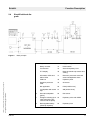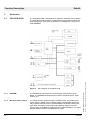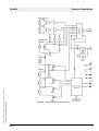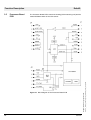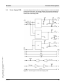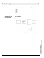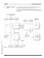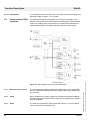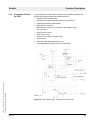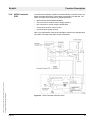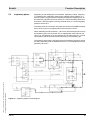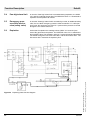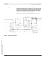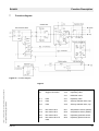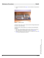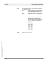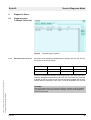
1
Technical Documentation EvitaXL Intensive Care Ventilator Revision 5.0 5664.590 9036054 Because you care Contents General 1 Symbols and Definitions 3 2 Notes 3 Function Description 1 General 7 2 Basic principle 7 All rights reserved. Copyright reserved. K5664590IECIVZ.fm 09.03.06 3 2.1 Control panel .......................................................................................................................... 8 2.2 Electronics .............................................................................................................................. 8 2.3 Pneumatics ............................................................................................................................. 8 2.4 Simplified block diagram ........................................................................................................ 9 Electronics 10 3.1 CPU PCB 68332 .................................................................................................................. 10 3.2 CO2 Carrier PCB .................................................................................................................. 12 3.3 CO2 measurement ............................................................................................................... 15 3.4 CO2 sensor .......................................................................................................................... 16 3.5 Processor Board PCB .......................................................................................................... 18 3.6 Power Supply PCB ............................................................................................................... 19 3.7 Power pack ........................................................................................................................... 20 3.8 Graphic Controller 8 PCB ..................................................................................................... 21 3.9 Communication PCB (optional) ............................................................................................ 24 3.10 Pediatric Flow PCB (optional) .............................................................................................. 26 3.11 IFCO Carrier PCB for additional optional features ............................................................... 27 3.12 SmartCare PCB (option) ...................................................................................................... 28 3.13 Pneumatic Controller PCB ................................................................................................... 29 3.14 HPSV Controller PCB ........................................................................................................... 33 I Contents 4 5 6 7 Pneumatics 34 4.1 Gas connection block ........................................................................................................... 35 4.2 Parallel mixer ........................................................................................................................ 38 4.3 Inspiratory block ................................................................................................................... 42 4.4 Patient system ...................................................................................................................... 44 4.5 PEEP/PIP valve .................................................................................................................... 46 Theory of operation 47 5.1 AIR supply ............................................................................................................................ 47 5.2 O2 supply ............................................................................................................................. 48 5.3 Inspiratory phase .................................................................................................................. 49 5.4 Paw high alarm limit ............................................................................................................. 50 5.5 Emergency pressure relief mechanism (safety valve) .......................................................... 50 5.6 Expiration .............................................................................................................................. 50 Gas mixture 52 6.1 Correcting the oxygen cartridge valve .................................................................................. 52 6.2 Dependence on the supply pressure .................................................................................... 52 Function diagram 53 Maintenance Procedures 1 Cooling-air filter 1.1 Ambient-air filter 2.1 II Replacing the ambient-air filter ............................................................................................. 59 Lithium battery (CPU 68332 PCB) 3.1 59 61 Replacing the lithium battery (CPU 68332 PCB) .................................................................. 61 K5664590IECIVZ.fm 09.03.06 3 Replacing the cooling-air filter ..............................................................................................57 All rights reserved. Copyright reserved. 2 57 Contents 4 Real-time clock 4.1 63 Replacing the real-time clock ............................................................................................... 63 Service Diagnosis Mode 1 General 69 2 Call-up of service diagnosis mode 71 3 Diagnosis ’Front’ 72 3.1 4 5 Diagnosis ’Electronic’ 73 4.1 Diagnosis page ’Processor’ .................................................................................................. 73 4.2 Diagnosis page ’Sensors’ ..................................................................................................... 76 4.3 Diagnosis page ’add. HW’ .................................................................................................... 78 Diagnosis ’Pneumatic’ 79 5.1 Diagnosis page ’Processor’ .................................................................................................. 79 5.2 Diagnosis page ’Sensors’ ..................................................................................................... 80 5.3 Diagnosis page ’Valves’ ........................................................................................................ 83 Diagnosis ’Other’ 85 6.1 Diagnosis page ’Lokbook’ (error list) .................................................................................... 85 6.2 Diagnosis page ’Option Release’ ......................................................................................... 88 6.3 Diagnosis page ’SW Info’ ..................................................................................................... 88 All rights reserved. Copyright reserved. K5664590IECIVZ.fm 09.03.06 6 Diagnosis page ’Processor’ .................................................................................................. 72 III Contents Schematics and Diagrams 1 Piping and function diagram 91 Annex Test List Technical Information K5664590IECIVZ.fm 09.03.06 All rights reserved. Copyright reserved. IV General 1 2 EvitaXL 1 Symbols and Definitions General WARNING A WARNING statement provides important information about a potentially hazardous situation which, if not avoided, could result in death or serious injury. CAUTION A CAUTION statement provides important information about a potentially hazardous situation which, if not avoided, may result in minor or moderate injury to the user or patient or in damage to the equipment or other property. NOTE A NOTE provides additional information intended to avoid inconvenience during operation. Definitions according to German standard DIN 31051: 2 Notes Inspection = examination of actual condition Maintenance = measures to maintain specified condition Repair = measures to restore specified condition Servicing = inspection, maintenance, and repair This Technical Documentation conforms to the IEC 60601-1 standard. Read each step in every procedure thoroughly before beginning any test. Always use the proper tools and specified test equipment. If you deviate from the instructions and/or recommendations in this Technical Documentation, the equipment may operate improperly or unsafely, or the equipment could be damaged. It is our recommendation to use only Dräger parts and supplies. The information in this Technical Documentation is confidential and may not be disclosed to third parties without the prior written consent of the manufacturer. All rights reserved. Copyright reserved. Version 3.0_ Released_Printed on_09.03.06_KGeneral.fm The maintenance procedures described in this Technical Documentation may be performed by qualified service personnel only. These maintenance procedures do not replace inspections and servicing by the manufacturer. This Technical Documentation is for the purpose of information only. Product descriptions found in this Technical Documentation are in no way a substitute for reading and studying the Instructions for Use/Operating Manual enclosed with the product at the time of delivery. Know-how contained in this Technical Documentation is subject to ongoing change through research and development and Dräger Medical reserves the right to make changes to this Technical Documentation without notice. 5664.590 3 General EvitaXL 4 5664.590 Version 3.0_ Released_Printed on_09.03.06_KGeneral.fm All rights reserved. Copyright reserved. NOTE Unless otherwise stated, reference is made to laws, regulations or standards (as amended) applicable in the Federal Republic of Germany for equipment used or serviced in Germany. Users or technicians in all other countries must verify compliance with local laws or applicable international standards. Function Description 5 6 Function Description 1 General The machine is a time-controlled, constant-volume long-term ventilator for adults and children. 2 Basic principle The machine communicates via a serial interface (CAN) and consists of the following assemblies: – Control panel – Electronic assembly – Pneumatic assembly Figure 1 All rights reserved. Copyright reserved. Version 4.1_ Released_Printed on_09.03.06_F5664590_Function_description.fm EvitaXL 5664.590 Assemblies of the machine 7 Function Description Control panel The control unit is the interface between the machine and the operator. The control unit is used to set parameters, it displays measured values, and generates warnings. The control unit comprises the following subassemblies: – 15“ TFT display – Membrane keypad – Touchscreen with resistive touch – Rotary encoder – Graphic Controller 8 PCB – Connector PCB Electronics The electronic assembly is the central control unit. The electronic assembly includes the CPU 68332 PCB, the CO2 Carrier PCB with the Processor PCB and the Power Supply PCB, and the power pack (Communication PCB, Pediatric Flow PCB, IFCO Carrier PCB, and the SpO2 PCB as option). 2.3 Pneumatics The pneumatic assembly controls the pneumatic valves following preset ventilation parameters. The pneumatic assembly includes an independent microprocessor system and the valve control. The pneumatic assembly comprises the Pneumatic Controller PcB, the HPSV Controller AIR/O2 PCB, the PEEP valve, the mixer, the compressed-gas connection, the flow sensor, and the O2 sensor. All rights reserved. Copyright reserved. 2.2 8 5664.590 Version 4.1_ Released_Printed on_09.03.06_F5664590_Function_description.fm 2.1 EvitaXL EvitaXL 2.4 Simplified block diagram All rights reserved. Copyright reserved. Version 4.1_ Released_Printed on_09.03.06_F5664590_Function_description.fm Figure 2 5664.590 Function Description Basic principle 1 Keys 13 Supply voltages 2 Rotary encoder 14 Power switch 3 Touchscreen 15 Second inspiratory Paw 4 TFT display 16 Reset pneumatics processor and venting 5 Information LEDs and Alarm LEDs 17 Electronic processor reset and second loudspeaker alarm 6 CAN bus 18 Inspiratory Paw 7 Graphics processor reset 19 O2 sensor 8 Not applicable 20 FiO2 (HPSV mixer) 9 Loudspeaker with sound 21 chip AIR (HPSV mixer) 10 Second loudspeaker (piezo) flow sensor 11 Voltage monitoring (acti- 23 vates reset of the processors and the piezo) Expiratory valve with PEEP 12 Rechargeable battery (Goldcap capacitor) Expiratory Paw 22 24 9 Function Description 3.1 CPU PCB 68332 The CPU 68332 PCB is integrated in the electronic assembly of the machine. The CPU 68332 PCB includes an independent microprocessor system, two external interfaces, three internal interfaces, the loudspeaker control and a serial EEPROM. Figure 3 Block diagram of the 68332 PCB 3.1.1 EEPROM The EEPROM is connected to the synchronized, serial interface of the 68332. The EEPROM characterizes the machine (enabled options, serial number, etc.). 3.1.2 Microprocessor system The microprocessor systems consists of a 68332 CPU, a 512 kB randomaccess memory (RAM), and a 1 MB electrically programmable and electrically erasable read-only memory (flash EPROM). The RAM is battery-buffered. When the battery is being replaced a Goldcap capacitor ensures voltage supply of the RAM. Programming of the flash EPROMs is only possible if the system identifies the “SERVICE-Q” signal. 10 5664.590 Version 4.1_ Released_Printed on_09.03.06_F5664590_Function_description.fm Electronics All rights reserved. Copyright reserved. 3 EvitaXL Function Description 3.1.3 RS232 interface The CPU 68332 PCB provides an RS232 interface in the Evita. The interface is labeled COM1. Optocouplers electrically isolate the RS232 interface from the machine. 3.1.4 ILV port The ILV interface allows for independent lung ventilation with two machines. The ILV interface is not electrically isolated. Pin 3 of the ILV interface is provided with a filler plug. This filler plug prevents confusion with the RS232 interface. 3.1.5 Driver The driver adjusts the access times between the 68332 CPU, the clock and the DUART. 3.1.6 Clock The clock makes sure that the current time is displayed. The clock is batterybuffered. This is to ensure that the clock is supplied with the required operating voltage after the device is switched off. 3.1.7 DUART The DUART (Dual Universal Asynchronous Receiver/Transmitter) has two serial interfaces and digital inputs and outputs. The SpO2 module and the CO2 module are connected to the serial interfaces. 3.1.8 DC/DC converter The DC/DC converter generates the voltage “+5 V ISO” required for the interface. The input voltage of the DC/DC converter is +5V. 3.1.9 CAN interface The CAN interface is a fast, serial interface. Via the CAN interface the control unit can communicate with the electronic and pneumatic assemblies. The transmission rate is 800 kbit/s. 3.1.10 Bus driver Via the bus driver, the signals from the address bus, the data bus, and the control bus are transmitted to the motherboard. The 68332 CPU uses the bus driver to communicate with the optional printed circuit boards installed on the motherboard (currently the Pediatric flow PCB (optional Neoflow feature)). 3.1.11 Sound generator The sound generator controls the loudspeaker in the control unit. The sound generator includes the sound volume control and the tone generation of the loudspeaker. The sound volume is controlled by the DUART. 3.1.12 Reset logic The CPU 68332 PCB uses a reset signal to reset (restart) the control unit and the pneumatic assembly. A reset is also triggered when the +5 V operating voltage is not reached (too low or too high). The pneumatic assembly can also send a reset signal to the CPU 68332 PCB, thus resetting the CPU 68332 PCB. The reset logic controls and displays the resets. All rights reserved. Copyright reserved. Version 4.1_ Released_Printed on_09.03.06_F5664590_Function_description.fm EvitaXL 5664.590 11 Function Description CO2 Carrier PCB The CO2 Carrier PCB is integrated in the electronic assembly of the Evita. The printed circuit board includes the mount and the electrical isolation of the CO2 module and the SpO2 module, the mains voltage failure logic, the temperature measurement and the voltage monitoring. Block diagram of the CO2 Carrier PCB All rights reserved. Copyright reserved. Figure 4 12 5664.590 Version 4.1_ Released_Printed on_09.03.06_F5664590_Function_description.fm 3.2 EvitaXL All rights reserved. Copyright reserved. Version 4.1_ Released_Printed on_09.03.06_F5664590_Function_description.fm EvitaXL 5664.590 Function Description Figure 5 Block diagram of the CO2 Carrier PCB, part 1 13 EvitaXL Block diagram of the CO2 Carrier PCB, part 2 3.2.1 Electrical isolation Optocouplers electrically isolate the printed circuit boards from the interfaces. The printed circuit board is provided with plug-in contacts. The SpO2 and CO2 modules are plugged into these plug-in contacts. The X3 connector is part of the optional “SpO2” module and is not equipped. 3.2.2 Mains voltage failure logic The mains voltage failure logic monitors the mains voltage supply. In the event that a mains voltage failure occurs while the machine is operating an audible alarm will sound. 14 5664.590 All rights reserved. Copyright reserved. Figure 6 Version 4.1_ Released_Printed on_09.03.06_F5664590_Function_description.fm Function Description EvitaXL 3.2.3 Voltage monitoring Function Description The microprocessor monitors the following voltages: – 15 V – +10 V – +24 V – +12 V – +5 V All voltages are present at a voltage divider. An A/D converter reads out the respective voltages. The CPU 68332 PCB reads out the AD converter. 3.2.4 Measurement of temperature and pressure A temperature sensor measures the current temperature. The temperature sensor is a thermistor (NTC). A temperature hybrid outputs the respective analog voltage value. The output signal from the temperature hybrid is transmitted to an A/D converter which converts the analog voltage value in a digital value. The CPU 68332 PCB reads out the digital value. A pressure sensor measures the current ambient pressure. The output signal from the pressure sensor is transmitted to an A/D converter which converts the analog voltage value in a digital value. The CPU 68332 PCB reads out the digital value. CO2 measurement The CO2 measuring system comprises three modules: – CO2 sensor – Processor Board PCB – Power Supply PCB Figure 7 All rights reserved. Copyright reserved. Version 4.1_ Released_Printed on_09.03.06_F5664590_Function_description.fm 3.3 5664.590 Block diagram of the CO2 measurement 15 Function Description 3.4 CO2 sensor EvitaXL The CO2 sensor comprises the CO2 measuring unit and a microprocessor system. A lamp generates a light spectrum of up to 4.5 m. This light travels through the cuvette and two sapphire discs and reaches the detectors. The detectors emit electrical signals depending on the CO2 concentration. The microprocessor analyzes these signals and transmits them to the Processor Board PCB via an RS232 interface. The CO2 measuring unit is kept at a constant temperature to avoid condensation. 16 5664.590 Version 4.1_ Released_Printed on_09.03.06_F5664590_Function_description.fm Sectional view of the CO2 sensor All rights reserved. Copyright reserved. Figure 8 All rights reserved. Copyright reserved. Version 4.1_ Released_Printed on_09.03.06_F5664590_Function_description.fm EvitaXL 5664.590 Function Description Figure 9 Block diagram of the CO2 sensor 17 Function Description Processor Board PCB The Processor Board PCB controls the heating (CO2 measuring unit) and the measured-data transfer of the CO2 sensor. 18 All rights reserved. Copyright reserved. Figure 10 Block diagram of the Processor Board PCB 5664.590 Version 4.1_ Released_Printed on_09.03.06_F5664590_Function_description.fm 3.5 EvitaXL EvitaXL All rights reserved. Copyright reserved. Version 4.1_ Released_Printed on_09.03.06_F5664590_Function_description.fm 3.6 Power Supply PCB Function Description The Power Supply PCB provides the supply voltages for the Processor Board PCB and the CO2 sensor. The supply voltages are electrically isolated from the machine. The CO2 measured values are transmitted to the CPU 68332 PCB via the Power Supply PCB. Figure 11 5664.590 Block diagram of the Power Supply PCB 19 Function Description 3.7 Power pack EvitaXL The switched-mode power pack provides the following output voltages: – +24 V – +15 V – -15 V – +12 V – +5 V The output voltages are short-circuit-proof. 3.7.1 DC module (option in converted Evita 4 or Evita 2 dura units) The DC module makes sure that the device is powered in the event of a mains voltage failure. 20 5664.590 Version 4.1_ Released_Printed on_09.03.06_F5664590_Function_description.fm All rights reserved. Copyright reserved. Figure 12 Schematic circuit diagram of the switched-mode power pack EvitaXL 3.8 Graphic Controller 8 PCB Function Description The Graphic Controller 8 PCB is fitted to the control unit. Connection to the electronic assembly is made via a 15-pin SUB-D connector. All rights reserved. Copyright reserved. Version 4.1_ Released_Printed on_09.03.06_F5664590_Function_description.fm The printed circuit board includes an independent processor system, the voltage supply of the control unit, the interface to the electronic assembly and the display control. Figure 13 Block diagram of the Graphic Controller 8 PCB 5664.590 21 Function Description 3.8.1 MPC 850 EvitaXL The power PC “MPC 850” has a maximum clock frequency of 80 MHz. The bus frequency rate is 40 MHz. – 32-bit RISC microprocessor – 2 kB data cache, 1 kB program cache – MMU (Memory Management Unit) – On-chip emulation debug mode – Timer, bus monitor, watchdog, interrupt controller, closk synthesizer, JTAG interface – Memory controller – CPM (Communications Processor Module) – 4 baud rate generators – 2 SCC (Serial Communication Controller) – 2 SMC (Serial Management Controller) – 1 SPI – 1 I2C – 3.3 V operation with 5 V-tolerance inputs 3.8.2 SDRAM The RAM has a memory area of 16 MB. This memory area is provided by two SDRAMs with 4 Mbit x 16 bit each. 3.8.3 Flash EPROM The program of the control unit is stored in the flash EPROM. It has a total capacity of 8 MB. The flash EPROMs are connected to the MPC 850 through a logic circuit in order to avoid unintentional changing of the contents. The logic circuit avoids that data is written without a connector being connected to the “COM1” interface. 3.8.4 LED Control The seven keys on the membrane keypad have a status LED each. In order to activate a status LED, the MPC 850 sends signals to a parallel port. This parallel port triggers the respective driver of the status LED. 3.8.5 Key inputs All keys are connected to ground. For interference suppression purposes, the key inputs are provided with ferrite cores and suppressor capacitors. 3.8.6 Loudspeaker monitoring The MPC 850 monitors the current across the loudspeaker. To this end, a 5ohm resistor is looped in the loudspeaker lead as a combination of eight 10ohm resistors. Capacitors tap the voltage present at the 5-ohm resistor and supply it to a differential amplifier. The amplified signal is available at a comparator. 3.8.7 Reset generator The 3.3-V reset generator DS1819A delivers the reset signals for the MPC 850. 3.8.8 CAN controller The CAN controller 82527 is connected to the MPC 850 through level converters. The CAN controller is supplied with 5 V. 22 5664.590 All rights reserved. Copyright reserved. The control knob key and all other key are connected to the MPC 850. Version 4.1_ Released_Printed on_09.03.06_F5664590_Function_description.fm The MPC 850 contains the following components: EvitaXL 3.8.9 ADuC 812 Function Description The microcontroller ADuC 812 controls the control knob and the touchscreen. Rotary transducer input The rotary transducer supplies two signals that are phase-shifted by 90 degrees. The microcontroller ADuC 812 scans both signals periodically (at approx. 1 ms period duration) thus determining the position of the rotary transducer. Touchscreen control The glass pane used on the control unit is coated and conductive. In front of it, there is a foil which is also coated and conductive. The foil's coating resistance is approx. 1 kohm. Electrodes are attached to the foil (at the top and bottom) and to the glass pane (at the left and right). When a finger touches the glass pane, the front foil is pressed against the glass pane thus creating a conductive connection. The position of the finger is calculated as follows: A current flows from top to bottom. The glass pane is switched to high resistance. The voltages are measured from top to bottom. The conductive, coated foil functions as a voltage divider the tap point of which is formed by the contact point of the finger. The Y coordinate is determined by measuring the voltage. Now the foil becomes high-resistant and a current flows across the glass pane from the left to the right instead. The X coordinate is determined by measuring the voltage. All rights reserved. Copyright reserved. Version 4.1_ Released_Printed on_09.03.06_F5664590_Function_description.fm The glass pane has a 8-wire design. That means that two electrodes each are attached to the edges. Changes in resistance on the glass pane itself or in the leads have no influence on the measurement result. A 4-wire measurement allows a current to flow across two electrodes, the reference voltage is then measured at the other two electrodes. 3.8.10 Graphic controller The graphic controller MB86290A generates graphic signals and includes character operations. The graphic controller is connected to the MPC 850, it occupies an address area of 64 MB. The output signals are analog. The video memory has 16 MB. 3.8.11 Voltage supply The control units uses the 24 V supplied from the power pack to generate the following voltages: – 12 V (15“ TFT display), can be switched off with MPC 850 – 5 V (ADuC 812) – 3.3 V (MPC 850) – 2.5 V (grafic controller) 3.8.12 Switched-mode regulator The switched-mode regulator (DC/DC converter) converts the 24 V into 12 V. A second switched-mode regulator (DC/DC converter) converts the 24 V into 5 V. 3.8.13 Series regulators Two series regulators filter any interference from the DC/DC converter. As a result, the voltages (3.3 V and 2.5 V) do not receive any clock signals from the DC/DC converter. 5664.590 23 EvitaXL 3.8.14 Comparators The comparators make sure that the 5-V converter only starts operating at an operating voltage of approx. 17 V or higher. 3.9 The CommunicationPCB is integrated in the electronic assembly of the machine. The printed circuit board includes an independent microprocessor system, the voltage supply of the interfaces, an internal CAN interface, an external CAN interface, two RS232 interfaces and two analog outputs. Communication PCB (optional) 3.9.1 Microprocessor system The microprocessor system comprises the 68332 CPU, one 512-KB RAM, and one 1-MB flash EPROM (electrically programmable and erasable readonly memory). 3.9.2 Uprog Uprog generates the voltage required for programming the flash EPROMs. An enable logic prevents unintentional supply of the programming voltage to the flash EPROMs. 3.9.3 Reset The reset logic generates a defined reset after power-up. The CPU 68332 can be reset by the CPU 68332 PCB. 24 5664.590 All rights reserved. Copyright reserved. Figure 14 Block diagram of the Communication PCB Version 4.1_ Released_Printed on_09.03.06_F5664590_Function_description.fm Function Description Function Description 3.9.4 CAN interfaces The Communication PCB is not connected to the data bus of the CPU 68332 PCB. The data are transmitted via an internal CAN interface (Controller Area Network – fast, serial interface). The external CAN interface is electrically isolated from the machine. Electrical isolation is made by means of optocouplers. 3.9.5 RS232 Interfaces The Communication PCB provides an RS232 interface in the machine. The interfaces are labeled COM2 and COM2. The interfaces are electrically isolated from the machine. Electrical isolation is made by means of optocouplers. 3.9.6 Analog outputs The analog outputs supply voltages between 0 V and 4.095 V. The assignment of analog outputs is freely selectable. The resolution of the output voltage is 1m V per bit. 3.9.7 DC/DC converter The DC/DC converters generate +5V ISO each for the voltage supply of the interfaces. The input voltages of the DC/DC converters are +5 V. 3.9.8 EEPROM The EEPROM stores internal data of the interface. The EEPROM has a 2 kB capacity. All rights reserved. Copyright reserved. Version 4.1_ Released_Printed on_09.03.06_F5664590_Function_description.fm EvitaXL 5664.590 25 Function Description 3.10 Pediatric Flow PCB (optional) EvitaXL The Pediatric Flow PCB is integrated in the electronic assembly. The printed circuit board has two flow measuring channels for connection of the Babylog flow sensor, one four-channel multiplexer, one 12-bit A/D converter, and one interface to the CPU 68332 PCB. The Babylog flow sensor measures the flow. The Babylog flow sensor is equipped with two measuring wires. One measuring wire is covered by a plastic bar, the Babylog flow sensor recognizes the direction of the flow. A measuring bridge analyzes the flow. 3.10.2 Multiplexer The multiplexer consists of four analog-value selectors. The software controls the analog-value selectors. The multiplexer transmits the flow sensor measurement signals “CGND and Uref LIMIT” to a buffer (AMP). Then the measurement signals are transmitted to an A/D converter (ADC). 3.10.3 A/D converter The input voltage of the A/D converter ranges from 0 V to 10 V. The A/D converter converts the flow measurement signals into digital data. The CPU PCB controls the A/D converter and the multiplexer via an interface (DATA OUT, DATA IN). The voltage drop across the multiplexer, the buffer and the A/D converter is measured using the “UREF LIMIT” reference voltage and can be taken into account when measuring the flow. All rights reserved. Copyright reserved. 3.10.1 Flow Measurement 26 5664.590 Version 4.1_ Released_Printed on_09.03.06_F5664590_Function_description.fm Figure 15 Block diagram of the Pediatric Flow PCB EvitaXL 3.11 IFCO Carrier PCB for additional optional features Function Description The IFCO Carrier PCB functions as carrier board for other optional features; it supports the nurse call and Remote Pad (cable remote control) functions and one additional ambient pressure sensor (optional). Figure 16 Block diagram of the IFCO Carrier PCB 3.11.1 Nurse Call The nurse call transmits top-priority alarms (!!!) displayed on the screen to, e.g., a central station. An alarm is also transmitted if the internal loudspeaker for audible alarms fails. The alarm is reset automatically as soon as the cause of the alarm disappears. The alarms are suppressed during the boot phase (start phase of the device). The central station alarm signaling is carried out by relay contacts. The alarm status can be determined by scanning these relay contacts. An alarm is considered to be triggered if contacts 3 and 5 of the nurse call connectors are closed by the relay contacts. These relay contacts are electrically isolated from the rest of the electronics. A bistable relay is used in order to keep this alarm signaling function active even when the power supply fails. All rights reserved. Copyright reserved. Version 4.1_ Released_Printed on_09.03.06_F5664590_Function_description.fm The nurse call function monitors the contacts of the power switch thus being able to detect whether the device is switched on or off. A power failure in the device can thus be detected. This alarm (power failure) can be cancelled by switching the device off. However, the device must be switched off within a defined time window. This time window is dependent on the charge status of specific capacitors. The time window is typically 2 minutes. 3.11.2 Remote Pad The Remote Pad is a cable remote control that is connected to the IFCO Carrier PCB. The Remote Pad has 6 key to control the ventilator. The Remote Pad is also provided with alarm LEDs. The inputs and outputs of the Remote Pads are short-circuit protected and protected against inadvertent wrong connections. 3.11.3 Pressure sensor (optional) The measured value supplied by the ambient pressure sensor on the IFCO Carrier PCB is evaluated by the safety software. This measured value is used to monitor the ambient pressure sensor on the CO2 Carrier PCB. 5664.590 27 Function Description 3.12 SmartCare PCB (option) EvitaXL The SmartCare PCB allows the patient to be weaned much faster from the ventilator. The PCB has a microcontroller, an EEPROM, an SDRAM, a flash EPROM, a reset generator and “CAN” and “Ethernet” interfaces. The microcontroller controls the hardware of the SmartCare PCB. 3.12.2 EEPROM The serial, rewritable memory module “EEPROM” stores the SmartCare PCB's data. The EEPROM has a 16 kByte capacity. 3.12.3 SDRAM The SDRAM is a synchronous RAM with a capacity of 32 MBytes. 3.12.4 Flash EPROM The flash EPROM (electrically programmable and electrically erasable ROM) has a capacity of 16 MBytes. 3.12.5 Reset generator The reset generator generates reset signals for the microcontroller. 3.12.6 Ethernet LTX 905 The “Ethernet” interface allows the communication with external devices. The “Ethernet” interface is electrically isolated from the machine. Electrical isolation is made by means of an optocoupler. 3.12.7 CAN Intel 82527 The “CAN Intel 82527” interface allows the communication with other microcontrollers in the device. The “CAN Intel 82527” interface is connected directly to the Motherboard PCB. 28 5664.590 Version 4.1_ Released_Printed on_09.03.06_F5664590_Function_description.fm 3.12.1 Microcontroller All rights reserved. Copyright reserved. Figure 17 Block diagram of the SmartCare PCB EvitaXL All rights reserved. Copyright reserved. Version 4.1_ Released_Printed on_09.03.06_F5664590_Function_description.fm 3.13 Pneumatic Controller PCB Function Description The Pneumatic Controller PCB is located in the pneumatic assembly. The printed circuit board provides the following functions: – Supply pressure measurement – Inspiratory and expiratory airway pressure measurement – Esophageal pressure measurement – Measurement of the flow – Measurement of the O2 concentration in the respiratory gas – Fan monitoring – Solenoid valve control – PEEP valve control – Interface to the HPSV Controller PCBs – CAN Interface – 68332 CPU with RAM and flash memory – Serial EEPROM for storage of device configuration Figure 18 Flow measurement, Pneumatic Controller PCB 5664.590 29 EvitaXL 3.13.1 Pressure measurement Two pressure sensors measure the pressure. The respective pressure sensors measure the pressure during the inspiratory phase and the expiratory phase. The airway pressure signals are transmitted to a multiplexer. A zero calibration of the pressure sensors is carried out automatically every three minutes. 3.13.2 Flow Measurement The flow sensor works according to the principle of a constant-temperature hot-wire flowmeter. Respiratory gas flows along a very thin, electrically heated platinum wire in a measuring tube. The wire is heated to a temperature of 180 degrees centigrade and kept at this temperature with a closedloop control system. If gas flows past this wire, heat is dissipated. The larger 30 5664.590 All rights reserved. Copyright reserved. Figure 19 Pneumatic Controller PCB block diagram Version 4.1_ Released_Printed on_09.03.06_F5664590_Function_description.fm Function Description EvitaXL Function Description the gas volume per time unit flowing past, the higher the heat dissipation. The heating power required to keep the wire at a constant temperature is a measure of the gas flow. 3.13.3 Cleaning of the flow sensor The control for cleaning (glowing) of the flow sensor supplies a defined current to both measuring wires. During calibration the measuring wires begin to glow and burn any impurities. The sensor is cleaned when pressing the “flow calibration” key or automatically after drug nebulization. The cleaning process occurs during the next inspiratory phase or after 15 seconds at the latest. 3.13.4 Oxygen measurement The O2 sensor works according to the galvanic cell principle. Oxygen molecules contained in the gas mixture to be measured diffuse through a plastic diaphragm into the electro-chemical cell and are reduced at the noble metal electrodes. At the same time a base electrode is being oxidized. The base electrode is spent by the oxidation process and thus determines the life of a sensor. The current flowing through the cell is proportional to the oxygen partial pressure in the gas mixture to be measured. 3.13.5 Fan monitoring At the front panel of the machine a fan is mounted to limit the temperature and the O2 concentration in the electronic unit of the pneumatic assembly in case of failure. The electronics monitors the fan. 3.13.6 Multiplexer The multiplexer consists of 16 analog-value selectors. The software controls the analog-value selectors. The multiplexer routes the measurement signals from the pressure sensors, the O2 amplifier, the FAN UREF and the flow sensor to a buffer. The output signals of the buffer are then available at an A/D converter. 3.13.7 Solenoid valves Two power drivers control the solenoid valves. A comparator monitors the power driver outputs for the nebulizer and the O2/Air switchover. The power drivers can be switched off from the electronic unit. 3.13.8 PEEP valve control A voltage-controlled current source with power MOSFET controls the PEEP valve. A quad operational amplifier serves to adapt the D/A converter output signal to the current range of the PEEP valve. The CPU controls the D/A converter. All rights reserved. Copyright reserved. Version 4.1_ Released_Printed on_09.03.06_F5664590_Function_description.fm Provided the pressure and temperature of the gas mixture to be measured are kept constant, the measured value will be directly proportional to the oxygen partial pressure. The O2 amplifier on the O2 Top PCB is mounted externally on the inspiratory block The output signal is transmitted to the O2 Contact PCB via spring contacts. From there the output signal is transferred to the Pneumatic Controller PCB. The O2 cell is also connected to the O2 Top PCB via spring contacts. The PEEP valve control is calibrated to the PEEP valve. The calibration data are stored in the serial EEPROM. 3.13.9 HPSV interface 5664.590 The status lines of the HPSV Controller PCB are led to the Pneumatic Controller PCB via the pneumatics motherboard. Two bus drivers transmit the data to the data bus of the CPU. The data are transmitted to the HPSV Controller PCB by two power drivers. The data are accepted by “power swing” of the respective chip-select pin. 31 EvitaXL The CAN interface comprises a CAN controller and a series-connected driver. The CAN controller is directly connected to the data bus of the CPU. The control unit, the electronics and the pneumatics communicate via a CAN interface. The transmission rate is 1 Mbit/s. 3.13.11 Microprocessor system The microprocessor system on the Pneumatic Controller PCB consists of a 68332 CPU, a 256 kByte flash EPROM (electrically programmable and erasable read-only memory) and a 256 kByte RAM. 3.13.12 Serial EEPROM The serial EEPROM stores the data of the pneumatics. The EEPROM has a 128 Byte capacity. All rights reserved. Copyright reserved. 3.13.10 CAN Interface 32 5664.590 Version 4.1_ Released_Printed on_09.03.06_F5664590_Function_description.fm Function Description EvitaXL 3.14 HPSV Controller PCB Function Description The pneumatic assembly contains two identical HPSV Controller PCBs. The board slot determines which of the boards is assigned to O2 and AIR. The HPSV Controller PCB comprises the following functions: – Microcontroller with EPROM and RAM – A/D converter for measurement of supply pressure – D/A converter for current set-point specification – Closed-loop circuit for current control – Power transistor (power source) All rights reserved. Copyright reserved. Version 4.1_ Released_Printed on_09.03.06_F5664590_Function_description.fm Note: The characteristic of the HPSV cartridge is stored in the cartridge itself. The HPSV Controller PCB reads out this chracteristic. Figure 20 HPSV Controller PCB with HPSV 5664.590 33 Function Description 4 Pneumatics EvitaXL The machine needs a driving gas pressure (AIR and O2) of 2.7 to 6 bar. Dräger gas connection block/FAS gas connection block – Parallel mixer or mixer block – Pressure sensors – PEEP/PIP valve – Inspiratory block – patient system Figure 21 Layout of the pneumatic subassemblies 34 5664.590 Version 4.1_ Released_Printed on_09.03.06_F5664590_Function_description.fm – All rights reserved. Copyright reserved. The pneumatic assembly consists of the following subassemblies: EvitaXL 4.1 Gas connection block Function Description The gas connection block comprises the “O2” gas connection (M12x1 female) and the “compressed air” connection (M 20x1.5 male). The following connections are available: NIST, DISS (USA) and DIN. The connections are fitted with filters F1.1 and F1.2 (metal fiber web). The check valves D1.1 (AIR) and D1.2 (O2) prevent the gas from flowing back into the central gas supply system. The pressure regulators DR1.1 and DR1.2 are set to 2 bar. The control gas flows past the DR1.1 to the 3/2-way valve Y1.1, from there to the emergency valve Y1.3, to the PEEP/PIP valve Y4.1 and finally to the emergency valve Y3.1. The gas also flows to the expiratory pressure sensor S6.2 (purge flow) via the restrictor R1.1 (0.08 L/min). Gas flows to the nebulizer via the 3/2-way valve Y1.4, if appropriately adjusted. Figure 22 Functional diagram of the gas connection block All rights reserved. Copyright reserved. Version 4.1_ Released_Printed on_09.03.06_F5664590_Function_description.fm In the event of “AIR” supply failure, the machine will switch over to O2 supply (O2 switchover function) 5664.590 35 Function Description 4.1.1 Characteristics of various gas connection blocks EvitaXL Characteristics of the FAS gas connection block: – Connector plate – Pressure regulator Figure 23 Dräger gas connection block (left) and FAS gas connection block (right) DR1.1 AIR pressure regulator DR1.2 O2 pressure regulator Y1.1 3/2-way solenoid valve, O2/AIR Y1.2 3/2-way solenoid valve pressure, sensor calibration inspiration Y1.3 3/2-way solenoid valve, venting Y1.4 3/2-way solenoid valve, nebulizer All rights reserved. Copyright reserved. The gas connection blocks are interchangeable since their mounts for attaching to the machine are identical. External distinguishing feature of the “Dräger gas connection block”: – four fixing screws External distinguishing feature of the FAS gas connection block: – 36 two fixing screws 5664.590 Version 4.1_ Released_Printed on_09.03.06_F5664590_Function_description.fm Legend EvitaXL Function Description All rights reserved. Copyright reserved. Version 4.1_ Released_Printed on_09.03.06_F5664590_Function_description.fm Figure 24 Dräger gas connection block (left), FAS gas connection block (right) 5664.590 37 Function Description 4.2 Parallel mixer EvitaXL The parallel mixer is a fast, electrically controllable proportional valve for gas flows between 5 and 180 L/min at supply pressures of 3 to 6 bar. Partial flows of less than 5 L/min are pulsed at a constant flow of 5 L/min. The supply gases compressed air (AIR) and oxygen (O2) available at the parallel mixer have a supply pressure of 2.7 bar to 6 bar. The parallel mixer mixes the two gases in accordance with the set parameters. The parallel mixer supplies the inspiratory gas to the patient. The parallel mixer consists of the following components: – Mixer connection block – 1 cartridge valve with displacement sensor system for compressed air (AIR) – 1 cartridge valve with displacement sensor system for oxygen (O2) – 2 supply pressure sensors measuring the inlet pressure of the supply gases 4.2.1 38 Mixer connection block The two cartridge valves are mounted to the mixer connection block. The inspiratory gases in the mixer connection block are supplied to the respective cartridge valve. The respiratory gas available at the outlet of the cartridge valves is mixed in the mixer connection block and supplied to the inspiratory unit. 5664.590 All rights reserved. Copyright reserved. Figure 25 Parallel mixer Version 4.1_ Released_Printed on_09.03.06_F5664590_Function_description.fm The HPSV Controller PCBs control the parallel mixer electrically. The control signals are transmitted to the parallel mixer via the Pneumatic Motherboard PCB and the Pneumatic Controller PCB. EvitaXL 4.2.2 Cartridge valves (HPS valves O2 and AIR) Function Description The cartridge valve (HPS valve = HPSV = high-pressure servo-valve) supplies a defined amount of gas to the patient in accordance with the preset adjustment parameters for e.g. inspiration, trigger pressure, leak flow compensation. Figure 26 Cartridge valve (HPS valve O2; HPS valve AIR) During expiration the supply gas is available at the cartridge valve and at the supply pressure sensor In the cartridge valve the ball “A” is pressed into the valve seat “B”; this action closes the cartridge valve (see the following Figure). All rights reserved. Copyright reserved. Version 4.1_ Released_Printed on_09.03.06_F5664590_Function_description.fm During inspiration, the drive system applies a current to the cartridge valve. The drive system is equipped with a coil working according to the principle of a moving coil of the type used e.g. in loudspeakers. The plunger is deflected in proportion to the supplied current and pushes ball “A” out of valve seat “B”. This causes an annular gap. The cartridge valve opens and gas flows to the patient. Figure 27 Sectional view of the cartridge valve Consequently, the size of the annular gap determines the gas flow. The annular gap between the ball and the valve seat is determined by the deflection of the plunger (i.e., by the displacement of the ball from the valve seat). The deflection is measured and controlled by a displacement measuring system. 5664.590 39 Function Description EvitaXL A supply pressure sensor at the cartridge valve measures the supply pressure of the gas to be dosed. The supply pressure at the cartridge valve is also used in the calculation of the gas flow. Twice the pressure for the same width of gap will produce twice the flow. A larger width of gap (annular gap) or a higher supply pressure results in a higher flow. The flow is determined indirectly by the displacement signal and the supply pressure. The cartridge valves supply a flow of 5 to 180 L/min. The plunger displacement depends on the supply pressure. The supply pressure is between 3 and 6 bar absolute. For a flow requirement of 120 L/min and a supply pressure of 5 bar the displacement will be approx. 0.2 mm. For a flow requirement of 120 L/min and a supply pressure of 1.5 bar the displacement will be approx. 0,6 mm. As the parallel mixer must permanently operate with high precision over the full flow range, it is measured and the data (non-linearity) are stored in an EEPROM on the Displacement Sensor PCB. Therefore no calibration is required when the cartridge valves are replaced. The cartridge valves must not be interchanged since they are specifically dimensioned and fitted for each individual gas. 4.2.3 Displacement sensor system The displacement sensor system measuring the position of the plunger in the valve is integrated in the cartridge valve. The displacement sensor system consists of the displacement measuring system and the Displacement Sensor PCB. The two circuits of the cartridge valves of parallel mixers are operated asynchronously in parallel (AIR, O2). To avoid beat interferences, the frequencies of the two oscillators must differ by a minimum of 200 kHz. Therefore the two cartridge valves have two different frequencies. The cartridge valves are measured at a special test stand. 40 5664.590 All rights reserved. Copyright reserved. As the displacement output signal is not linear to the gas flow, the characteristic of the cartridge valve is measured and stored in the EEPROM. The micro-controller on the HPSV PCB thus balances the non-linearity of the cartridge valve. Version 4.1_ Released_Printed on_09.03.06_F5664590_Function_description.fm The displacement measuring system is a differential transformer. The a.c. voltage applied to the primary winding of the transformer has a frequency of approx. 1 MHz. The two secondary windings are switched such that their output voltages balance out. If the ferrite core (plunger of the cartridge valves) moves in the differential transformer, the output voltage of the displacement sensor system will change. EvitaXL 4.2.4 Supply pressure sensors Function Description The supply pressure sensors are calibrated to absolute pressure (0 bar). They measure the inlet pressure of the supplied gas. The supply pressure sensor is fitted with a P/U converter generating a pressure-dependent output voltage. Measuring range 0 -7 bar Sensitivity 1.58 V/bar 8 mV/bar Offset voltage 300 mV 30 mV The supply pressure sensors are linked via a flex-strip to the Displacement Sensor PCB. The Displacement Sensor PCB is installed in the cartridge valves. 4.2.5 Airway pressure sensors The pressure sensor mount comprises the airway pressure sensors S6.1 for the inspiratory side and S6.2 for the expiratory side. During inspiration, S6.1 monitors the airway pressure “high” (Paw high) and the airway pressure “low” (Paw low). Measuring range 140 mbar Sensitivity 36.5 mV/mbar 0.3 mV/mbar Offset voltage 1.74 V 0.04 V Calibration of the airway pressure sensors All rights reserved. Copyright reserved. Version 4.1_ Released_Printed on_09.03.06_F5664590_Function_description.fm The solenoid valves Y6.1 and Y6.2 expose the relevant airway pressure sensors to atmospheric pressure at specific time intervals, consequently, the airway pressure sensors are automatically calibrated. The airway pressure sensors S6.1 and S6.2 are zero-calibrated every 3 minutes. (Calibration of the possible electronic zero drift). To do so, the solenoid valves Y6.1 and Y6.2 are subsequently exposed to atmospheric pressure and the airway pressure sensors automatically calibrated. Figure 28 Function diagram of the airway pressure sensors 5664.590 41 Function Description 4.3 Inspiratory block EvitaXL The safety valve D3.3 limits the pressure in the inspiratory line to 100 mbar max. In the event of compressed air failure or mains voltage failure the pneumatically controlled emergency air valve Y3.1 will open so that the patient can breathe ambient air passing the filter F3.1. The non-return valve D3.1 prevents rebreathing of the air through the inspiratory line. The spring-loaded non-return valve D3.2 allows pressure to drop if valve Y3.1 opens. In the case of emergency air spontaneous breathing the patient can exhale through the expiratory valve Y5.1 on account of the spring loading (5 mbar) thus preventing rebreathing. The inspiration block is provided with the plug-in connection for the oxygen sensor. The restrictor R1.2 limit the drug nebulizer flow to 9 L/min. If the gas supply or the voltage supply fails, the emergency air valve Y3.1 will no longer be controlled. The patient can breathe spontaneously through filter F3.1, non-return valve D3.1 and emergency air valve Y3.1. Figure 29 Emergency air function diagram 42 5664.590 Version 4.1_ Released_Printed on_09.03.06_F5664590_Function_description.fm Emergency air All rights reserved. Copyright reserved. 4.3.1 EvitaXL Function Description Figure 30 Inspiratory block All rights reserved. Copyright reserved. Version 4.1_ Released_Printed on_09.03.06_F5664590_Function_description.fm Legend 5664.590 1-1a Patient connection (inspiration) 2-2a Nebulizer port 3-3a Esophageal pressure P1 4-4a Esophageal pressure P2 5 10 mbar pressure relief valve D3.2 6 100 mbar pressure relief valve D3.3 (adjustable; NOTE: until middle of ’96 valve slot milled in the block, after ’96 separate piece screwed onto the block) 7 Emergency pressure relief mechanism control 8 Pressure measurement (inspiration) 9 O2 calibration control 10 O2 sensor chamber (behind the O2 amplifier) 11 O2 calibration purge flow outlet 12 Emergency air non-return valve D3.1 in O2 amplifier 13 O2 calibration diaphragm lattice Y3.3 with R3.1 14 Valve Y3.1 15 O2 amplifier 43 Function Description 4.4 Patient system EvitaXL The expiratory gas flows from the patient directly to the expiratory valve Y5.1. The copper measuring line at the 8a connection has a germicidal effect and connects the expiratory side to the pressure sensor S6.2. The expiratory valve has a transmission ratio of approx. 1:1. The non-return valve D5.1 allows flow in one direction only and makes sure that gases do not travel backwards. The flow sensor S5.1 measures the expiratory flow. Figure 31 Patient system function diagram Figure 32 Sectional view of the patient system Control pressure of 3 mbar => expiratory pressure of 0 mbar All rights reserved. Copyright reserved. Control pressure of 33 mbar => expiratory pressure of 33 mbar 44 5664.590 Version 4.1_ Released_Printed on_09.03.06_F5664590_Function_description.fm The ratio between the control pressure at the 7a connection of the PEEP/PIP valve and the resulting pressure at the expiratory port is linear to the following values: EvitaXL 4.4.1 Patient system with RS water trap Function Description The water trap avoids flow measurement faults caused by water droplets. Such faults may occur if the water traps on the ventilation hoses are not positioned at the lowest possible point. In this case the condensation water is collected in the water trap of the patient system. The collector jar of the water trap can be removed during operation. The opening to the patient system is sealed automatically. Figure 33 Function diagram of the patient system with water trap All rights reserved. Copyright reserved. Version 4.1_ Released_Printed on_09.03.06_F5664590_Function_description.fm Figure 34 Sectional view of the patient system with water trap 5664.590 45 Function Description 4.5 PEEP/PIP valve EvitaXL The PEEP/PIP valve Y4.1 consists of a diaphragm valve acting as a flowcontrol device and the linear drive whose plunger closes the diaphragm valve. A coil drives the PEEP/PIP valve Y4.1. The preset ventilation defines the settings. A computer program processes these settings, and the coil is driven by an appropriate current. The PEEP valve opens and adjusts a pressure proportional to the adjusted electric current (Note: 0 mA will correspond to –1 mbar, 500 mA to 120 mbar). The PEEP/PIP valve Y4.1 controls the expiratory valve Y5.1 in the patient system via a servo-line. The solenoid valve Y1.3 supplies control gas to the restrictor R4.1 and to the PEEP/PIP valve Y4.1. The non-adjustable restrictor R4.1 is set to a flow of 3.5 L/min. Depending on the PEEP setting the plunger coil is activated causing an appropriate servo-pressure to be applied to the diaphragm of the expiratory valve. The software compares the preset and measured airway pressures. This comparison is a measure of the Pneumatic Controller PCB’s control action on the PEEP/PIP valve. The PEEP/PIP valve is calibrated to the electronics. The calibration data are stored on the Pneumatic Controller PCB. Figure 36 Section view of the PEEP valve 46 5664.590 Version 4.1_ Released_Printed on_09.03.06_F5664590_Function_description.fm All rights reserved. Copyright reserved. Figure 35 PEEP valve function diagram 5 Theory of operation 5.1 AIR supply Function Description AIR flows through the filter F1.1 passing the non-return valve D1.1 reaching the mixer and flow control unit (pressure sensor S2.1 and HPSV Y2.1). At the same time, the gas flows to the 3/2-way solenoid valve Y1.1 via the pressure regulator DR1.1 which is set to 2 bar. From here the gas flows through the 3/2-way solenoid valve Y1.3 to the emergency air valve Y3.1 which closes. Furthermore, the gas passes the restrictor R4.1 to reach the PEEP/PIP valve Y4.1 and from there – depending on the setting – to the expiratory valve Y5.1. Finally, the gas passes the restrictor R1.1 to flow to the expiratory pressure sensor S6.2 connecting line on the patient side. At this point, expiratory humidity is prevented from reaching the pressure sensor S6.2. Figure 37 AIR supply function diagram All rights reserved. Copyright reserved. Version 4.1_ Released_Printed on_09.03.06_F5664590_Function_description.fm EvitaXL 5664.590 47 Function Description 5.2 O2 supply EvitaXL O2 flows through the filter F1.2 passing the non-return valve D1.2 reaching the mixer and flow control unit (pressure sensor S2.2 and HPSV Y2.2). At the same time, the gas flows to the 3/2-way solenoid valve Y1.1 via the pressure regulator DR1.2 which is set to 2 bar. O2/AIR changeover valve The 3/2-way solenoid valve Y1.1 switches under the following circumstances: – If the “AIR” supply fails – When the O2 sensor is calibrated – When the nebulizer function (depending on FiO2 setpoint) is triggered If these conditions are given, the servo-system will be supplied with O2. 48 5664.590 All rights reserved. Copyright reserved. 5.2.1 Version 4.1_ Released_Printed on_09.03.06_F5664590_Function_description.fm Figure 38 O2 supply function diagram EvitaXL 5.3 Inspiratory phase Function Description Depending on the settings (O2 concentration, inspiratory volume, frequency, Ti, inspiratory flow, inspiratory pressure) the cartridge valves (HPSVs Y2.1 and Y2.2) open. The gas flows to the patient through the inspiratory port. At the same time, gas flows to the O2 sensor S3.1 and to the safety valve D3.3; from there, it flows through the 3/2-way solenoid valve Y6.1 to the inspiratory pressure sensor S6.1. The safety valve D3.3 is fixed to 100 mbar and serves as an additional safety device in the event of a complete failure of the electronic control. When calibrating the O2 sensor S3.1, valve Y3.3 disconnects the sensor from the inspiratory gas. The O2 sensor S3.1 is supplied with 100% O2 from the valve Y1.2, the restrictor R1.3, the restrictor R3.1 and the valve Y3.2. The O2 concentration and the flow will not be influenced by the inspiratory gas. All rights reserved. Copyright reserved. Version 4.1_ Released_Printed on_09.03.06_F5664590_Function_description.fm The pressure sensors S6.1 and S6.2 monitor the inspiratory pressure. During the entire inspiratory time the PEEP/PIP valve Y4.1 provides pressure to the expiratory valve Y5.1. Figure 39 Inspiratory phase function diagram 5664.590 49 EvitaXL 5.4 Paw high alarm limit In case the “Paw high” alarm limit is exceeded during inspiration, the HPSV Y2.1 and Y2.2 interrupt the gas flow. The PEEP/PIP valve Y4.1 is switched to expiration and the patient can exhale. 5.5 Emergency pressure relief mechanism (safety valve) In case the “Paw high” alarm limit is exceeded by 5 mbar, an additional safety valve, the so-called “emergency pressure relief mechanism” Y1.3 will open. As a result, the emergency air valve Y3.1 opens and the pressure is vented through the non-return valve D3.2. 5.6 Expiration At the start of expiration the cartridge valves (HPSV Y2.1 and Y2.2) are closed. No gas flows to the patient. The PEEP/PIP valve Y4.1 is switched to the set PEEP value. The expiratory valve Y5.1 is also relieved and the patient can exhale through the non-return valve D5.1 and the flow sensor S5.1. The flow sensor S5.1 measures the expiratory flow. 50 All rights reserved. Copyright reserved. Figure 40 Expiratory phase function diagram 5664.590 Version 4.1_ Released_Printed on_09.03.06_F5664590_Function_description.fm Function Description EvitaXL 5.6.1 Drug nebulizer Function Description After pressing the “drug nebulizer” button, the drug nebulizer is switched on for 30 minutes. At the same time, the solenoid valve Y1.4 switches through in the flow-active inspiratory phase. The restrictor R1.2 supplies the drug nebulizer with drive gas. At the end of the inspiratory gas supply phase, the solenoid valve Y1.4 also switches back. The minute volume remains constant while the flow setting is being corrected. After completion of the drug nebulization the flow sensor S5.1 is automatically glowed clean. Note: the drug nebulizer needs a minimum inspiratory flow of 16 L/min. All rights reserved. Copyright reserved. Version 4.1_ Released_Printed on_09.03.06_F5664590_Function_description.fm Figure 41 Nebulizer function diagram 5664.590 51 Function Description EvitaXL 6 Gas mixture One cartridge valve (HPSV) each controls the air flow or the oxygen flow, directly from the supply lines. Both sub-flows are joined in the parallel mixer and then supplied to the inspiration block. Depending on the set oxygen concentration (FiO2: 0.21 to 1.00), the total flow to be metered is split into an “AIR” sub-flow and an “oxygen” sub-flow. Sub-flows of less than 5 L/min are no longer metered continuously, but in pulses lasting at least 8 ms and with a constant flow value of 5 L/min. This results in a pulse/pause ratio that corresponds to the sub-flow value. 6.1 Correcting the oxygen cartridge valve Corresponding to its operating principle, the cartridge valve (HPSV) meters a mass flow. Owing to the differing gas density values of the compressed air and the oxygen, different volume flows would therefore be applied if these values were not corrected. Owing to the different gas density values, the portion of the inspiration flow demanded of the oxygen cartridge valve is therefore increased by 5%. 6.2 Dependence on the supply pressure With regard to the gas supply, the operating range of the machine is specified from 2.7 bar to 6 bar gauge pressure. The machine monitors this operating range with the aid of the absolute pressure sensors on the cartridge valves on the basis of the following criteria: – Supply pressure always higher than 1.2 relative/absolute – At no flow, supply pressure higher than 2.5 bar relative At low supply pressures (below 3 bar gauge pressure), the cartridge valve can no longer apply high flows without errors, i.e. the actually supplied flow is less than the demanded flow. The inspiratory flow must be limited for reasons of flow accuracy and thus also for oxygen concentration accuracy reasons. Prior to the start of an inspiration, the maximum inspiratory flow for spontaneous inspiration of the cartridge valve is defined on the basis of the measured supplied gauge pressure: Psupply > 4 bar absolute --> max. inspiratory flow = 180 L/min All rights reserved. Copyright reserved. For mandatory inspirations, the inspiration flow is limited by the setting to 120 L/min. 52 5664.590 Version 4.1_ Released_Printed on_09.03.06_F5664590_Function_description.fm Psupply < 4 bar absolute --> max. inspiratory flow = 150 L/min EvitaXL 7 Function Description Function diagram Figure 42 Function diagram All rights reserved. Copyright reserved. Version 4.1_ Released_Printed on_09.03.06_F5664590_Function_description.fm Legend 5664.590 AIR Air connection Y3.1 Emergency air valve O2 Oxygen connection Y3.3 Inspiratory valve Y4.1 PEEP/PIP valve F1.1 Filter Y5.1 Expiratory valve F1.2 Filter Y6.1 3/2-way solenoid valve, insp. F3.2 Filter Y6.2 3/2-way solenoid valve, exp. D1.1 Non-return valve S2.1 AIR pressure sensor (HPSV) D1.2 Non-return valve S2.2 O2 pressure sensor (HPSV) D3.1 Non-return valve S6.1 Inspiratory pressure sensor D3.2 Non-return valve 10 mbar S6.2 Expiratory pressure sensor 53 EvitaXL D3.3 Non-return valve 100 mbar S3.1 O2 sensor D5.1 Non-return valve S5.1 Flow sensor DR1.1 AIR pressure regulator R1.1 Restrictor 0.08 L/min/2bar DR1.2 O2 pressure regulator R1.2 Restrictor 9 L/min/2bar R1.3 Restrictor 0.4 L/min/2bar R3.1 Restrictor (hole in the diaphragm in Y3.3) 0.25 L/min/1.4 bar R4.1 Restrictor 3.5 L/min/2bar 3/2-way solenoid valve, O2/AIR Y1.2 3/2-way solenoid valve calibration O2 sensor Y1.3 3/2-way solenoid valve, venting Y1.4 3/2-way solenoid valve, nebulizer Y2.1 AIR HPSV (high-pressure servo-valve) parallel mixer Y2.2 O2 HPSV (high-pressure servo-valve) parallel mixer All rights reserved. Copyright reserved. Y1.1 54 5664.590 Version 4.1_ Released_Printed on_09.03.06_F5664590_Function_description.fm Function Description Maintenance Procedures 55 56 EvitaXL 1 Cooling-air filter 1.1 Replacing the cooling-air filter Maintenance Procedures 1. Remove cooling-air filter (Figure 1 /1) from its slot on the back of machine. Figure 1 Rear view of the machine 2. If cooling-air filter is dirty, clean it in warm water with detergent added; allow to dry well. 3. If cooling-air filter is faulty, dispose of it according to local waste disposal regulations. All rights reserved. Copyright reserved. Version 1.1_ Released_Printed on_09.03.06_W5664590_Wartung_Kuehlluftfilter.fm 4. Insert cooling-air filter in slot (white side inside), taking care not to crease it, see Figure 1/1. 5664.590 57 58 5664.590 Version 1.1_ Released_Printed on_09.03.06_W5664590_Wartung_Kuehlluftfilter.fm All rights reserved. Copyright reserved. Maintenance Procedures EvitaXL EvitaXL 2 Ambient-air filter 2.1 Replacing the ambient-air filter Maintenance Procedures 1. Swivel inspiratory port down (Figure 2/1). Figure 2 Front view of the machine, protective cover Figure 3 Protective cover All rights reserved. Copyright reserved. Version 1.1_ Released_Printed on_09.03.06_W5664590_Wartung_Raumluftfilter.fm 2. Loosen screw (Figure 3/1) with an appropriate screwdriver and remove the protective cover. 5664.590 59 Maintenance Procedures EvitaXL 3. Remove the ambient-air filter (Figure 4/1) from the tabs on the protective cover. Figure 4 Ambient-air filter If ambient-air filter is dirty, clean it in warm water with detergent added; allow to dry well. Continue with step 4. If ambient-air filter is faulty, dispose of it according to local waste disposal regulations. 4. Slide new or cleaned ambient-air filter under the tabs on the protective cover, making sure the fitting position is correct, see Figure 4/1. 60 5664.590 Version 1.1_ Released_Printed on_09.03.06_W5664590_Wartung_Raumluftfilter.fm All rights reserved. Copyright reserved. 5. Replace the protective cover on the machine, and tighten the screw (Figure 3/1) with an appropriate screwdriver. EvitaXL 3 Lithium battery (CPU 68332 PCB) 3.1 Replacing the lithium battery (CPU 68332 PCB) Maintenance Procedures 1. Switch on the machine and wait 2 minutes (Note: the capacitor for power supply to the memory modules (RAM) needs to be charged). 2. Write down the customer-specific settings (alarm limits, screen set-up, etc.) so that you can re-enter them after replacing the lithium battery. 3. Switch off the machine. CAUTION Electrostatic discharge may damage the electronic components. When handling electrostatic sensitive devices, use a static-dissipative mat and a static dissipative wrist strap. 4. Create ESD conditions. Figure 5 Rear view of the machine CAUTION A data loss will occur if the RAM power supply is missing. Replace the lithium battery within one minute! When installing the lithium battery make sure that it is properly seated in its holder. All rights reserved. Copyright reserved. Version 1.1_ Released_Printed on_09.03.06_W5664590_Wartung_LithiumBatterie.fm 5. Remove the screws (Figure 5/1) on the CPU 68332 PCB (Note: The CPU 68332 PCB might also be in another slot than that shown here). 6. Remove the CPU 68332 from the machine. 5664.590 61 Maintenance Procedures EvitaXL 7. Remove the spent lithium battery (Figure 6/1) from the battery holder and dispose of according to local waste disposal regulations. Figure 6 Detail of the CPU PCB 8. Push the lithium battery into the battery holder (see Figure 6), making sure the polarity is correct. 9. Push the CPU 68332 PCB into the machine. Rear view of the machine 11. Check the electrical safety and the correct functioning of the device as described in the PMS procedure. 62 5664.590 Version 1.1_ Released_Printed on_09.03.06_W5664590_Wartung_LithiumBatterie.fm Figure 7 All rights reserved. Copyright reserved. 10. Secure the CPU 68332 PCB to the machine using the screws (Figure 7/1). EvitaXL 4 Real-time clock 4.1 Replacing the realtime clock Maintenance Procedures 1. Switch off the machine. 2. Unplug the power plug of the machine from the socket-outlet. CAUTION Electrostatic discharge may damage the electronic components. When handling electrostatic sensitive devices, use a static-dissipative mat and a static dissipative wrist strap. 3. Create ESD conditions. Figure 8 Rear view of the machine 5. Remove the CPU 68332 from the machine, and place it on the static-dissipative mat. All rights reserved. Copyright reserved. Version 1.1_ Released_Printed on_09.03.06_W5664590_Wartung_RealTimeClock.fm 4. Remove the screws (Figure 8/1) (Note: The CPU 68332 PCB might also be in another slot than that shown here). 5664.590 63 Maintenance Procedures EvitaXL 6. Carefully remove the real-time clock (Figure 9/1) from its IC socket. Figure 9 Detail of the CPU PCB 7. Dispose of the spent real-time clock according to local waste disposal regulations. NOTE If, in the next work step, the real-time clock is not fitted correctly it will not display the time and date. Make sure the fitting position is correct when fitting the real-time clock in the next work step. Figure 10 Real-time clock 9. Push the CPU 68332 PCB into the machine. 64 5664.590 Version 1.1_ Released_Printed on_09.03.06_W5664590_Wartung_RealTimeClock.fm All rights reserved. Copyright reserved. 8. Firmly push the new real-time clock into its IC socket, making sure the fitting position is correct (coding), see Figure 10. EvitaXL Maintenance Procedures 10. Secure the CPU 68332 PCB to the machine using the screws (Figure 11/1). Figure 11 Rear view of the machine 11. Plug the power plug of the machine into the socket-outlet. 12. Switch on the machine. 13. Using the rotary knob, set the current time and date in the “Configuration” and “Basic Settings” menu. All rights reserved. Copyright reserved. Version 1.1_ Released_Printed on_09.03.06_W5664590_Wartung_RealTimeClock.fm 14. Check the electrical safety and the correct functioning of the machine as described in the PMS procedure. 5664.590 65 66 5664.590 Version 1.1_ Released_Printed on_09.03.06_W5664590_Wartung_RealTimeClock.fm All rights reserved. Copyright reserved. Maintenance Procedures EvitaXL Service Diagnosis Mode 67 68 Evita XL 1 Service Diagnosis Mode General NOTE The complete Service Diagnosis Mode is only available in SW 6.n or higher The service diagnosis mode enables on-line information to be read out at any time during operation. The Service Diagnosis Mode user interface is always in English, no matter which language version is used in the unit. The diagnosis pages are split up as follows: Front: Readout of control panel data: Processor: Keypad test Loudspeaker monitoring RAM Test Electronic: Readout of electronics section data: Processor: Voltage supply Internal unit temperature AWT sensor inspiratory pressure Ambient pressure sensor RAM/ROM test results Service connector CAN SW options Sensors: Ambient pressure measurement Pediatric flow measurement CO2 measurement add. HW: IFCO-Carrier PCB All rights reserved. Copyright reserved. Version 1.1_ Released_Printed on_09.03.06_K5664590_Service_Diagnosis_Mode.fm SpO2 measurement (not provided for the time being) 5664.590 69 Service Diagnosis Mode Evita XL Pneumatic: Readout of pneumatics section data: Processor: RAM/ROM test results Fan monitoring Reference voltages Sensors: 4 airway pressure sensors Flow measurement Basic flow Pulse threshold O2 sampling Valves: Setting of switching valves HPSV (supply pressure, status, O2 measurement, flow) PEEP/PIP valve (calibration values) Nebulizer flow Logbook: Readout of error list Option Release: Enabling of options SW Info: Software information, e.g. SmartCare. 70 5664.590 Version 1.1_ Released_Printed on_09.03.06_K5664590_Service_Diagnosis_Mode.fm Special functions – error list and SW options: All rights reserved. Copyright reserved. Other: Evita XL 2 Call-up of service diagnosis mode Service Diagnosis Mode Service diagnosis mode can be called up at any time in the course of operation. This mode only involves data readout; settings are not altered. • Press the ’System Setup’ key. • Select the ’Service’ menu. • Enter the number code ’4655’. • Select the required menu. Call-up of service diagnosis mode All rights reserved. Copyright reserved. Version 1.1_ Released_Printed on_09.03.06_K5664590_Service_Diagnosis_Mode.fm Figure 1 5664.590 71 Service Diagnosis Mode 3 Diagnosis ’Front’ 3.1 Diagnosis page ’Processor’ Evita XL Figure 2 Diagnosis page ’Processor’ Keys pressed: Keypad test, determined by Graphics Controller PCB. 0 = key not pressed 1 = key pressed Important: Keys which affect screen content switch Evita out of diagnosis mode. Sound detected: Result of current measurement through loudspeaker in control panel. Detected flow of current through loudspeaker (= yes) continues to be displayed for 10 seconds. 72 5664.590 Version 1.1_ Released_Printed on_09.03.06_K5664590_Service_Diagnosis_Mode.fm Output of result of RAM test, Graphics Controller PCB. All rights reserved. Copyright reserved. RAM: Evita XL 4 Diagnosis ’Electronic’ 4.1 Diagnosis page ’Processor’ Service Diagnosis Mode Figure 3 Diagnosis page ’Processor’ 5V = 4.5 V to 5.5 V 12 V = 9.6 V to 14.4 V 15 V = 14 V to 18 V -15 V = -12 V to -18 V 24 V = 19.2 V to 28.8 V Important: The power pack is specified as follows: All rights reserved. Copyright reserved. Version 1.1_ Released_Printed on_09.03.06_K5664590_Service_Diagnosis_Mode.fm 5 V / 12 V / 15 V / - Power pack supply voltages, measured on the CO2 15 V / 24 V: Carrier PCB. Output of voltages and decimal values of AD conversion. There are no device error messages with the following values: 10 V: 5664.590 5V = 5.07 V to 5.23 V 12 V = 11.76 V to 12.24 V 15 V = 4.55 V to 15.45 V -15 V = -14.55 V to -15.45 V 24 V = 22.32 V to 24.72 V 10V reference voltage, generated from the 15V supply voltage on the CO2 Carrier PCB. Output of voltage and decimal value of AD conversion. Error message is given in the event of deviation greater than 4 %. Set value = 9.65 V to 10.35 V. 73 Evita XL GoldCap: Output of GoldCap voltage. The GoldCap capacitor supplies the substitute horn with current. Output of capacity and resistance value and decimal values of the AD conversion. After startup of the Evita ’???’ are displayed first. The first measured values will appear after approx. 10 minutes. Piezo: The current through the substitute horn is only measured on the old CO2 Carrier PCB. Piezo detected, >30 decimals (0.018 V). Piezo off, <30 decimals. PowerSW: Output of voltage at mains-switch auxiliary contact. Voltage is important for detecting mains failure. Output of voltage and decimal value of AD conversion. Mains switch on, <164 decimals (0.100 V). Mains switch off, >512 decimals (0.312 V). Batt ext.: Output of voltage of externally connected DC voltage supply (option DC module). Output of voltage and decimal value of AD conversion. AD1: Output of AD converter reference voltage 1. Output of voltage and decimal value of AD conversion. Set value approx. 2.500 V. AD2: Output of AD converter reference voltage 2. Output of voltage and decimal value of AD conversion. Set value approx. 2.500 V. TCPU [C]: Temperature inside unit; measured on CO2 Carrier PCB. Output of temperature in °C and voltage. Permissible temperature range <65 °C. The message ’Fan malfunction !’ is displayed as of 65 °C. (removed at 60 °C) and as of 70 °C the alarm ’Fan failure? !!!’ (removed at 65 °C). Tair [C]: AWT sensor respiratory-gas temperature. Output of temperature in °C and voltage. Pinsp [mbar]: Second channel of the inspiratory pressure sensor. Pambient [mbar]: Air pressure currently being used in Evita (filtered). Output of air pressure in mbar and voltage. The permissible measuring range is = 600 mbar to 1100 mbar. Result of EEPROM test. EEPROM D22 is located on the CPU 68332 PCB. All rights reserved. Copyright reserved. EEPROM: 74 5664.590 Version 1.1_ Released_Printed on_09.03.06_K5664590_Service_Diagnosis_Mode.fm Service Diagnosis Mode Evita XL Service Diagnosis Mode Loss of data: Output of data loss of RAM and EEPROM D22 on CPU 68332 PCB: no = no data loss yes = data loss. A data loss in the RAM may due to a flat battery on the CPU 68332 PCB. RAM: Result of RAM test on the CPU 68332 PCB. RAM-Comm: Result of RAM test on Communication PCB. Valid values are only output if the PCB fitted (option). ILV in/out: Outputs only defined with ILV ventilation. Service connector: Output of whether or not RS 232 cable with service encoding is connected to COM1 on CPU 68332 PCB. no - service encoding not recognized, normal operation yes - service encoding recognized, download of operating software or external service mode via PC possible. CAN components: Output of PCBs connected to internal CAN at CPU 68332 PCB (0 = not fitted, 1 = fitted). Sequence is as follows from left to right: Graphics Controller PCB / Pneumatic Controller PCB / Communication PCB / 5 x undefined SW options: The released options are output in the following form: Output form: ’1’_(option 0 - 7)_(option 8 - 15)_(option 16 23)_(option 24 - 31) Meaning: ’1’ = block 1 with 32 options (1 = option fitted, 0 = option not fitted) The following options are currently provided in block 1: Option 7 = SpO2 measurement Option 8 = CO2 measurement Option 9 = DC power pack Option 10 = Comfort Breath (PPS and tube compensation) All rights reserved. Copyright reserved. Version 1.1_ Released_Printed on_09.03.06_K5664590_Service_Diagnosis_Mode.fm Following data loss, the Evita attempts to restore the data. If this proves possible, the red alarm ’Loss of data !!!’ disappears from the screen. The Evita is OK if this alarm is no longer present when the unit is next switched on. 5664.590 75 Service Diagnosis Mode Diagnosis page ’Sensors’ Figure 4 Ambient Pressure: Output of ambient pressure measurement values: Pambient: Air pressure used in Evita. Raw: Current raw voltage from air pressure sensor with calculated air pressure. P_Reference: Air pressure established as air-pressure reference value when Evita is switched on. If the deviation from PAir or PO2 is more than 8 %, the message ’Execute device check’ is given. Pair / PO2: Air pressure of supply pressure sensors PAIR and PO2, determined in last device check. Pinsp: Second channel of the inspiratory pressure sensor. Pediatric flow measurement values. Valid values are only provided if option has been fitted. All rights reserved. Copyright reserved. Paediatric flow: Diagnosis page ’Sensors’ 76 5664.590 Version 1.1_ Released_Printed on_09.03.06_K5664590_Service_Diagnosis_Mode.fm 4.2 Evita XL Evita XL Service Diagnosis Mode CO2: CO2: Output of PCB type of the Signal Processor PCB of CO2 measurement on the CO2 Carrier PCB, e.g. ’DW HL’ or ’Andros 4210’ SW rev: Output of SW revision on Signal Processor PCB, e.g. ’6870277 1.11’ for Dräger software revision 1.11. Tdet / Twin: Output of decimal value of detector (Tdet) and window (Twin) temperature in CO2 sensor. Approx. 43 °C should have been attained in each case after 3 minutes. The temperatures may vary between 40 °C and 50 °C, depending on the operating conditions. 40 °C = 5326 41 °C = 5116 42 °C = 4916 43 °C = 4725 44 °C = 4543 45 °C = 4368 46 °C = 4201 48 °C = 3888 50 °C = 3602 Not provided for the time being. All rights reserved. Copyright reserved. Version 1.1_ Released_Printed on_09.03.06_K5664590_Service_Diagnosis_Mode.fm SpO2: CO2 measurement values. A list of important CO2 measurement data is given below: 5664.590 77 Service Diagnosis Mode 4.3 Evita XL Diagnosis page ’add. HW’ Figure 5 Diagnosis page ’add. HW’ 78 5664.590 Version 1.1_ Released_Printed on_09.03.06_K5664590_Service_Diagnosis_Mode.fm All rights reserved. Copyright reserved. IFCO Carrier PCB: Output whether IFCO Carrier PCB (option) is fitted or not (’PCB detected’). Evita XL 5 Diagnosis ’Pneumatic’ 5.1 Diagnosis page ’Processor’ Service Diagnosis Mode Diagnosis page ’Processor’ Periphery of processor: Status of processor system of Pneumatic Controller PCB and fan for cooling electronics in pneumatics section. Error message is given in the event of deviation. Fan must be detected within 1 minute. ADC: Output of reference voltages of Pneumatic Controller PCB. Error message is given in the event of deviation. Target values: Uref5V = 4.9 V to 5.1 V ADCref = 2.9 V to 3.1 V DACref = 2.9 V to 3.1 V All rights reserved. Copyright reserved. Version 1.1_ Released_Printed on_09.03.06_K5664590_Service_Diagnosis_Mode.fm Figure 6 5664.590 79 Service Diagnosis Mode Diagnosis page ’Sensors’ Figure 7 Diagnosis page ’Sensors’ Pressure Sensors: Output of measured values from the 4 airway pressure sensors insp., exp., oes and aux (oes and aux are envisaged for future options). Three values are output for each sensor: [mbar]: Pressure in mbar of calibrated sensor. [V] Output voltage of sensor; read in by Pneumatic Controller PCB. Voltage = Calibration voltage + sensitivity Sensitivity = 36.5 ±0.3 mV/mbar Measuring range = 140 mbar Cal [V] Calibration voltage of sensor (zero at ambient pressure) Set value = 1.74 ±0.50 V. 80 Paw [mbar]: Pressure Paw calculated in each case by insp. and exp. pressure sensor with allowance for tubing resistance. The permissible difference between the two values is 5 mbar. (PCB CPU): Comparison value in mbar. Output voltage of inspiratory pressure sensor is additionally read in on CO2 Carrier PCB (second channel). The max. difference with respect to Paw is 5 mbar. 5664.590 All rights reserved. Copyright reserved. The pressure at the Y-piece (Paw) is also calculated: Version 1.1_ Released_Printed on_09.03.06_K5664590_Service_Diagnosis_Mode.fm 5.2 Evita XL Evita XL Service Diagnosis Mode R [mbar/L/s]: Tubing resistance: insp: From inspiratory port to the Y-piece. exp: From the Y-piece to the expiratory port. Top row: Measured in operation by safety software. Bottom row: Measured in device check. These values differ as they are measured at different flow rates. C [mL/mbar]: Measured values of the expiratory flow measurement. Note: All values are displayed under BTPS conditions unless otherwise stated. Explanation: BTPS Based on 37 °C, ambient pressure + inspiratory pressure, 100 % relative humidity. All Evita measured values and settings are based on BTPS. NTPS Based on 20 °C, 1013 mbar, 100 % relative humidity. Corresponds to raw value of measured expiratory flow. NTPD Based on 20 °C, 1013 mbar, dry. The mixer delivers the flow under the following conditions. The Evita setting under BTPS is converted to NTPD for the mixer. [L/min]: Measured expiratory flow converted to BTPS. Corresponds to displayed value. [L/min] NTPD/S: Raw flow value measured under NTPS or NTPD conditions [V]: Flow measurement voltages in V: Uinop: Voltage set value >0.1 V, sensor probably OK if F0 and Fsig OK. ’Flow measurement inop. !!!’ is displayed if voltage is <0.1 V. F0: 4-fold amplified bridge voltage of the flow measurement. Set value in no-flow condition = 4.04 V. All rights reserved. Copyright reserved. Version 1.1_ Released_Printed on_09.03.06_K5664590_Service_Diagnosis_Mode.fm Flow Sensor: Inspiratory tubing compliance. Fsig: 2-fold amplified bridge voltage of the flow measurement. Set value in no-flow condition = 2.02 V. Cal DA: 5664.590 Decimal DA converter value for calibration of flow sensor Set value = 2200 to 3200. 81 Service Diagnosis Mode Evita XL Switch: Microswitch for detecting position of flow sensor: on - Flow sensor in right-hand operating position. off - Flow sensor not ready for operation in replacement position. NTPS -> BTPS: Factor for converting raw value of measured flow NTPS to displayed flow BTPS value. Permissible deviation from ’quotient’ = 5 %. Quotient: NTPS/BTPS conversion factor calculated in a different way. BTPS -> NTPD: Factor for converting flow BTPS to NTPD MVinsp [L/min]: Inspiratory minute volume calculated from actuation signals of mixer. The measured expiratory minute volume may be max. 20 % more than this value. ’Flow measurement inop’ is displayed if the difference is greater. The problem may be due to the following: - Flow measurement is faulty - Impermissible feed-in of external flow (e.g. by the nebulizer) - Mixer supplying excessive flow rate. 82 FiO2 [Vol%]: Measured O2 concentration, pressure-compensated. [V]: Amplified sensor voltage at Pneumatic Controller PCB input. This voltage is read in twice on this PCB. Refer to Cal [V] for permissible voltage range. Cal [V]: Amplified sensor voltage during calibration to 100 vol.% O2. Permissible range: 1.257 to 5.644 V. Voltage too low: Sensor spent. Voltage too high: O2 measurement is faulty (O2 amplifier or Pneumatic Controller PCB) Pmean O2: Current mean pressure in tubing system in mbar. Required for pressure compensation of O2 measurement. Cal P: Air pressure allowance in mbar on calibrating O2 measurement. 5664.590 Version 1.1_ Released_Printed on_09.03.06_K5664590_Service_Diagnosis_Mode.fm Measured values and calibration values for inspiratory O2 measurement. Output voltage of O2 sensor is amplified directly at the sensor. All rights reserved. Copyright reserved. O2 Sensor: Evita XL 5.3 Service Diagnosis Mode Diagnosis page ’Valves’ Figure 8 Valves: Diagnosis page ’Valves’ Actuation of switching valves in pneumatics section. For the valves Y1.1 and Y1.4 the actuation voltage is read back and output in the second value. Actuation and feedback must be identical. on: Valve actuated. All rights reserved. Copyright reserved. Version 1.1_ Released_Printed on_09.03.06_K5664590_Service_Diagnosis_Mode.fm off: Valve de-energized. 5664.590 Y1.1: O2/Air switching valve, off = Air. Y1.2: O2 measurement calibration valve, on = O2 measurement calibration. Y1.3: Safety valve, on = ventilation, off = safety shutdown active. Y1.4: Nebulizer valve, off = nebulizer off. Y6.1: Calibration valve for inspiration pressure sensor S6.1, on = calibration. Y6.2: Calibration valve for expiration pressure sensor S6.2, on = calibration. Yx.x: Future option; a total of 10 valves can be connected to the Pneumatic Controller PCB. 83 Service Diagnosis Mode Evita XL PEEP: Pressure: The absolute pressures for Air and O2 are output. Absolute pressure = rel. supply pressure + ambient pressure. Measuring range of supply-pressure sensors = 0 to 7 bar. Sensitivity = 1.58 V/bar ±8 mV/bar. Offset voltage = 300 mV ±30 mV. State: Status messages from the respective HPSV Controller PCB for O2 and Air: 0 = no error. 2 = supply pressure less than 2 bar absolute, pressure supply failure. 1, 3 to 15 = errors on HPSV Controller PCB or in HPSV cartridge. Values for PEEP/PIP valve Y4.1 Cal. values: Calibration values for actuation of PEEP/PIP valve. Valve or PCB replacement must be followed by calibration. Setting PEEP: PEEP setpoint input in mbar. Measured PEEP: PEEP measured by airway pressure measurement in mbar. Flow value set on the nebulizer. All rights reserved. Copyright reserved. Nebuliser Flow: Supply pressures and status of cartridge for O2 and Air. The set values for flow and FiO2 and the measured FiO2 value is output, as well. 84 5664.590 Version 1.1_ Released_Printed on_09.03.06_K5664590_Service_Diagnosis_Mode.fm HPSV: Evita XL 6 Diagnosis ’Other’ 6.1 Diagnosis page ’Lokbook’ (error list) Service Diagnosis Mode Figure 9 Structure of the error list All system errors (software and hardware) are stored in the error list. The system errors are stored as follows: First occurrence Last occurrence Code Count 24.01. 16:45 24.01. 16:45 LL.NN.MMM 1 24.01. 16:55 15.05. 07:25 LL.NN.MMM 4 The error messages are stored in chronological order. The most recent error message will appear at the bottom of the error list. If a specific error message is already on the list, only the most recent event will be updated and the error number will be incremented. In this case, no line will be added to the error list. CAUTION After each replacement of a processor board the software must be updated by DrägerService. Otherwise, different software versions would impair the function of the Evita. All rights reserved. Copyright reserved. Version 1.1_ Released_Printed on_09.03.06_K5664590_Service_Diagnosis_Mode.fm 6.1.1 Diagnosis page ’Logbook’ 5664.590 85 Service Diagnosis Mode Error code key LL = Allocation to a specific component, PCB, or software. NN = Type of error. MMM = More detailed description or enumeration. NN Description of message 00 XX XXX Normal monitoring. Stored in the user log only. 01 XX XXX Settings, etc. Stored in the user log only. 02 01 up to 61 001 up to 999 Errors that are detected by the safety software. 71 001 Loudspeaker not detected. 002 Flow measurement is faulty. 003 up to 006 GoldCap capacitor. 007 BOOT test is faulty. 008 Generation of auxiliary alarm. 009 The current through the piezo alarm generator is too high. 010 The current through the piezo alarm generator is too low. 011 The nebulizer valve monitoring is faulty. 012 The loudspeaker monitoring circuit has detected an error. 013 The loudspeaker monitoring circuit has detected an error. 014 +15 V is too low. 015 +10 V is too low. 016 AD conversion for O2 measurement is faulty. 017 Activation of O2/Air switching valve is faulty. 018 Wrong nebulizer gas. 019 Cold start detection is faulty. 020 Hardware initialization is faulty. 021 Different quartz times. 000 up to 006 Errors that are detected by the safety software. 007 up to 070 Errors that are detected by the ventilation software. XXX Control unit components. 72 03 86 MMM XX 5664.590 Version 1.1_ Released_Printed on_09.03.06_K5664590_Service_Diagnosis_Mode.fm LL All rights reserved. Copyright reserved. 6.1.2 Evita XL Evita XL Service Diagnosis Mode LL 04 MMM Description of message XX XXX Electronic assembly components. Components which are not located on the printed circuit boards. 01 XXX Power pack. XX XXX Pneumatics components. 01 XXX Fan 02 001 Reset-up line 002 Reset-down line 003 Disable line 04 001 up to 004 O2/Air switching valve 06 XX XXX Extension box components 07 XX XXX Software error (ROSI = operating system software) 08 XX XXX Future expansion 09 XX XXX Miscellaneous 10 XX XXX Pneumatics Controller PCB 11 XX XXX HPSV Controller Air PCB 12 XX XXX HPSV Controller O2 PCB 13 XX XXX CPU PCB 68332 98 001 BOOT error 14 XX XXX CO2 Carrier PCB 15 XX XXX Communication PCB 16 XX XXX Pediatric Flow PCB 17 XX XXX Graphic Controller PCB 18 XX XXX Pneumatics Motherboard PCB 19 XX XXX Electronics Motherboard PCB All rights reserved. Copyright reserved. 05 Version 1.1_ Released_Printed on_09.03.06_K5664590_Service_Diagnosis_Mode.fm NN 5664.590 87 Service Diagnosis Mode 6.2 Evita XL Diagnosis page ’Option Release’ Figure 10 Diagnosis page ’Option Release’ Code: Input of release codes for options. Figure 11 Diagnosis page ’SW Info’ Encoded software information about the installed software, e.g. SmartCare. 88 5664.590 Version 1.1_ Released_Printed on_09.03.06_K5664590_Service_Diagnosis_Mode.fm Diagnosis page ’SW Info’ All rights reserved. Copyright reserved. 6.3 Schematics and Diagrams 89 90 Version 1.2_ Released_Printed on_09.03.06_S5664590_Schematics_and_diagrams.fm 5664.590 Piping diagram (Dräger Gas supply block) Piping and function diagram Figure 1 1 Schutzvermerk DIN 34 beachten. Copyright reserved. EvitaXL Schematics and diagrams 91 92 Piping diagram (FAS Gas supply block) 5664.590 Version 1.2_ Released_Printed on_09.03.06_S5664590_Schematics_and_diagrams.fm Schutzvermerk DIN 34 beachten. Copyright reserved. Figure 2 Schematics and diagrams EvitaXL Version 1.2_ Released_Printed on_09.03.06_S5664590_Schematics_and_diagrams.fm Figure 3 Function diagram Schutzvermerk DIN 34 beachten. Copyright reserved. EvitaXL 5664.590 Schematics and diagrams 93 94 5664.590 Version 1.2_ Released_Printed on_09.03.06_S5664590_Schematics_and_diagrams.fm Schutzvermerk DIN 34 beachten. Copyright reserved. Schematics and diagrams EvitaXL Annex Test List Technical Information Test list (TL) Evita XL This test list can be processed with standard commercially available test aids and tools, but does not replace the inspections and maintenance work carried out by the manufacturer. Notes on field of application: Tests marked with the "check" symbol are listed in the test report. The test results are to be documented in the test report. These test instructions apply to software version 5.n. Evita XL 2005-07 Released - page 1 - Table of contents 1 Unit configuration 1. 1 1. 2 1. 3 1. 4 General Serial number (SN) Software version Operating hours 2 Electrical safety 2. 1 2. 2 2. 3 2. 4 Visual check General note Electrical safety to VDE 0751 Electrical safety to IEC 60-601/UL 60601-1 3 Function and condition test 3. 1 3. 2 3. 3 3. 4 3. 5 3. 6 3. 7 3. 8 3. 9 3.10 Accompanying documents Visual check Non-return valve in expiratory valve Power-on test Checking as per internal unit checklist Testing of safety-related valves Temperature measurement (option) CO2 measurement (option) Unit prior to handover Unit handover 4 Test equipment 4. 1 Standard commercially available test equipment 5 Tubing diagrams and pneumatic diagram 5. 1 5. 2 5. 3 Tubing diagram of pneumatic system with Dräger gas connection block Tubing diagram of pneumatic system with FAS gas connection block Pneumatic diagram Evita XL 2005-07 Released - page 2 - 1 Unit configuration 1.1 General The basic unit configuration covers the following components: - EvitaXL - Trolley - Ventilation tubing system - Expiratory valve - Temperature sensor (option) - CO2 sensor (option) 1.2 5 1.2.1 Serial number (SN) [______txt] EvitaXL Serial number (SN) of EvitaXL (Note: The serial number is located on the rating plate. 5 1.2.2 [______txt] Expiratory valve 1 Serial number (SN) of expiratory valve 1 5 1.2.3 [______txt] Control panel Serial number (SN) of control panel 1.3 5 1.3.1 Software version [______txt] Unit software version Connect the power plug of the unit to AC power supply. Switch the device on. The unit completes its self-test. Set unit to operating mode. Press "System Setup" button. The "System Setup" window is shown on the display. Press "Service" softkey. Read and note down the software version from the display. 1.4 5 1.4.1 Operating hours [______h] Unit operating hours Connect the power plug of the unit to AC power supply. Switch the device on. The unit completes its self-test. Evita XL 2005-07 Released - page 3 - Set unit to operating mode. Press "System Setup" button. The "System Setup" window is shown on the display. Press "Service" softkey. Read and note down the operating hours from the display. 2 5 2.1 Electrical safety [_______OK] Visual check - The unit's power supply cord is undamaged. - The screw-type terminal of the power cable is undamaged. - The power switch including power-switch protective cover is undamaged. The power-switch protective cover automatically covers the power switch. - The CO2 sensor, the housing and the connecting cable are undamaged. - The fitted fuse links match the ratings indicated on the power supply unit. [OK] 2.2 General note NOTICE: Devices that are connected to a network must be disconnected from this network first before performing electrical safety tests. Otherwise other devices that are connected to the network could be damaged. The following section details the additional tests of electrical safety to VDE 0751 and IEC 60601-1/UL 60601-1. Which standard is applied depends on the relevant national regulations. If necessary, make the following settings for the unit on the measuring devices: Protection class ”SK 1”, safety class ”BF”. 2.3 Electrical safety to VDE 0751 2.3.1 Medical systems When testing according to VDE 0751, test the system, not the individual devices. Systems must be handled as devices. A medical system is a combination of several devices of which at least one is a medical electrical device connected by functional connections or a movable multiple socket-outlet. Additional ground connections of medical systems such as data cables or similar should be disconnected during testing. Medical systems must be subjected to a visual check to find out whether individual units of the system have been replaced, added or removed in comparison to the previous configuration used for determination of the initial value. Any changes must be recorded. Measured values must be recorded as initial values after a change in the system. The sum of the leakage currents of the individual devices must not exceed the specified limit value. Evita XL 2005-07 Released - page 4 - Note A multiple socket outlet, if applicable, should be included in the test. 5 2.3.2 Protective earth conductor test according to VDE 0751 [_______OK] The value of the protective earth conductor resistance must not exceed 0.3 ohms in each case. 2.3.3 5 2.3.3.1 Device leakage current test to VDE 0751 [______μA] Initial value The initial measured value must not exceed 500 μA. INFO: Each initial measured value must be transferred to a new test report. 5 2.3.3.2 [______μA] Recurrent measurement The value of the repeat measurement may exceed the initial measured value by max. 50%, but must not exceed 500 μA. 2.3.4 5 2.3.4.1 Patient leakage current to VDE 0751, ILV port or temperature sensor Initial measured value, patient leakage current DC [______μA] INFO: Each initial measured value must be transferred to a new test report. The initial measured value must not exceed 10 μA. 5 2.3.4.2 Initial measured value, patient leakage current AC [______μA] INFO: Each initial measured value must be transferred to a new test report. The initial measured value must not exceed 100 μA. 5 2.3.4.3 Recurrent measurement, patient leakage current DC [______μA] The recurrent measurement must not exceed 10 μA. 5 2.3.4.4 Recurrent measurement, patient leakage current AC [______μA] The recurrent measurement must not exceed 100 μA. 2.3.5 Trolley multiple socket strip (option) INFO: The electrical safety test is performed within the system test, see note in test step 2.3.1. Evita XL 2005-07 Released - page 5 - 5 2.3.5.1 [_______OK] Fuse links The fuse links match the ratings on the rating plate. 2.4 5 2.4.1 Electrical safety to IEC 60-601/UL 60601-1 [______Ohm] Protective earth conductor resistance WARNING: Test the PE resistance with the power cable connected! The protective earth conductor resistance must not exceed 0.2 ohms in each case. 2.4.2 5 2.4.2.1 Earth leakage current [______μA] Normal condition N.C. The earth leakage current must not exceed 500 μA. 5 2.4.2.2 [______μA] Single fault condition S.F.C. Open circuit in neutral conductor. The earth leakage current must not exceed 1000 μA. Subsequently the earth leakage current test is repeated with the power plug rotated. This condition can be established internally on some testers. 5 2.4.2.3 [______μA] Normal condition N.C. The earth leakage current must not exceed 500 μA. 5 2.4.2.4 [______μA] Single fault condition S.F.C. Open circuit in neutral conductor. The earth leakage current must not exceed 1000 μA. 2.4.3 5 2.4.3.1 Patient leakage current, ILV port or temperature sensor [______μA] Normal condition N.C. The patient leakage current must not exceed 100 μA. 5 2.4.3.2 [______μA] Single fault condition S.F.C. Open circuit in neutral conductor. The patient leakage current must not exceed 500 μA. Subsequently the patient leakage current test is repeated with the power plug rotated. This condition can be established internally on some testers. Evita XL 2005-07 Released - page 6 - 5 2.4.3.3 [______μA] Normal condition N.C. The patient leakage current must not exceed 100 μA. 5 2.4.3.4 [______μA] Single fault condition S.F.C. Open circuit in power cable conductor. The patient leakage current must not exceed 500 μA. 2.4.4 5 2.4.4.1 Trolley multiple socket strip (option) [_______OK] Fuse links The fuse links match the ratings on the rating plate. 5 2.4.4.2 [______Ohm] Protective earth conductor resistance The protective earth conductor resistance of the socket outlets must not exceed 0.2 ohms in each case. 5 2.4.4.3 [______μA] Earth leakage current (N.C.) The earth leakage current must not exceed 50 μA. 5 2.4.4.4 [______μA] Single fault condition (S.F.C.) Open circuit in neutral conductor. The earth leakage current must not exceed 100 μA. Subsequently the earth leakage current test is repeated with the power plug rotated. This condition can be established internally on some testers. 5 2.4.4.5 [______μA] Earth leakage current (N.C.) The earth leakage current must not exceed 50 μA. 5 2.4.4.6 [______μA] Single fault condition (S.F.C.) Open circuit in neutral conductor. The earth leakage current must not exceed 100 μA. 3 5 3.1 Function and condition test [_______OK] Accompanying documents - Instructions for Use are available according to user (Note: Comply with national laws and standards!). - Instructions for Use of options are available according to the user (Note: Comply with national laws and standards!). - The Medical Products Logbook (applies to Germany only) is available according to the user (Note: Comply with national laws and standards!). [OK] Evita XL 2005-07 Released - page 7 - 3.2 Visual check Check condition of unit and essential accessories. 5 3.2.1 [_______OK] Housing The housing is not damaged or dirty. The housing has no corrosion damage. Also repair any paintwork damage. [OK] 5 3.2.2 [_______OK] Control and display elements The operating and display elements are not damaged or dirty. [OK] 5 3.2.3 [_______OK] AIR and O2 compressed gas ports The AIR and O2 compressed gas ports are undamaged. [OK] 5 3.2.3 [_______OK] Labelling The labeling, including on adhesive option labels, is complete and legible. [OK] 5 3.2.5 [_______OK] PCBs The PCBs are all affixed by two screws to the unit. [OK] 5 3.2.6 [_______OK] Sockets (sensor, communication) The connectors on the PCBs are undamaged. [OK] 5 3.2.7 [_______OK] Power supply unit The power supply unit is not damaged or dirty. [OK] 5 3.2.8 [_______OK] DC connection for external battery (option) The DC connection is undamaged. [OK] 5 3.2.9 [_______OK] Remote socket (optional) INFO: If a remote socket is installed on the Evita 4 with the "XL" option, it must be closed off by a cap. There must also be a warning label affixed next to the remote socket. The remote socket is closed off by a cap. The cap is undamaged. The warning notice is legible, and not dirty or damaged. [OK] Evita XL 2005-07 Released - page 8 - 5 3.2.10 [_______OK] Cooling-air fan on power pack The cooling air fan is not damaged or dirty. The cooling air fan rotates smoothly. Clean out the cooling air fan with a vacuum cleaner if it is dirty. [OK] 5 3.2.11 [_______OK] Cooling-air filter (on rear, right) The cooling air filter is not damaged, dirty or squashed. Replace the cooling air filter as necessary. [OK] Remove the front panel (control panel) to perform the following steps. 5 3.2.12 [_______OK] Cover The cover to the right of the inspiratory block is undamaged. [OK] Remove the screw from the cover and lay the cover aside. - The room air filter F3.1 in the cover is not damaged, dirty or squashed. - The fan behind the cover is not damaged or dirty. The fan rotates smoothly and is not dirt clogged. Vacuum the fan to clean it as necessary. - Unscrew O2 amplifier with non-return valve. The O2 amplifier with non-return valve D3.1 is not damaged or dirty. - Check expiry date of O2 sensor capsule. Replace the O2 sensor capsule as necessary. - The lip seal of the O2 sensor mount in the inspiratory block is undamaged. - The seal between the inspiratory block and the O2 amplifier is undamaged. Insert O2 sensor capsule into inspiratory block. Fit O2 amplifier with non-return valve on unit. - The inspiratory socket is not dirty or damaged. - The nebulizer port is identified by a nebulizer icon. The nebulizer port is not dirty or damaged. [OK] Fit cover on unit. 5 3.2.13 [_______OK] Expiratory block The flow sensor is undamaged. The flow sensor mount is not dirty or damaged. The joint seal between the flow sensor and the expiratory valve is undamaged and the connector seal is correctly seated. [OK] 5 3.2.13.1 [_______OK] Expiratory valve without water trap WARNING: When fitting, keep to the preferential direction of the plug with copper pipe! Visual check of individual components - see Fig.. The individual components of the expiratory valve are undamaged. Evita XL 2005-07 Released - page 9 - [OK] Assemble the expiratory valve(s) in functional condition. 5 3.2.13.2 [_______OK] Expiratory valve with water trap WARNING: When fitting, keep to the preferential direction of the plug with copper pipe! Visual check of individual components as described in previous test step plus additional visual check of individual components – see Figure. The individual components of the expiratory valve and the water trap are undamaged. [OK] Assemble the expiratory valve(s) in functional condition. 5 3.2.13.3 [_______OK] Expiratory valve mount The expiratory valve mount is not damaged or dirty. The expiratory valve locks safely into the mount. [OK] 5 3.2.13.4 Patient system heater ventilation grille (without old filter) [_______OK] The patient system heater ventilation grille is not dirty. Clean the ventilation grille, or suction it clean with a vacuum cleaner, as necessary (Note: The ventilation grille is fitted on the right under the expiratory valve. Block the fan during suction.). [OK] Evita XL 2005-07 Released - page 10 - 5 3.2.13.5 Dust protective filter of the patient system heater (new) [_______OK] The dust protective filter is not damaged, dirty or squashed. [OK] 5 3.2.13.6 [_______OK] Lip seals The lip seals between the expiratory valve and the unit are undamaged. Replace lip seals if necessary. [OK] 5 3.2.14 [_______OK] Control panel with attachment - The housing and touchscreen are not dirty or damaged. - The keypad and the control knob are undamaged. The labelling is complete and legible. - The control panel can be swiveled and locked in place. The control panel can be removed without problem. - The rail mounting with interlock is undamaged. - The cable winder is undamaged. - The control panel connecting cable is undamaged. The connecting cable is secured to the control panel and to the front with 2 screws each. - The interlock for mounting of the control panel is undamaged. - The lid of the base unit is undamaged. If no tray or Dräger monitor is fitted to the unit, the four openings in the lid must be closed off with sealing plugs. - The tray is undamaged. [OK] 5 3.2.15 [_______OK] CO2 sensor (option) - The housing with anti-kink sleeve is undamaged. The housing is bonded tight. - The cable with plug is undamaged. The cable insulation is undamaged. - The window in the CO2 sensor is clean and undamaged. - The mounting of the test filter on the connecting cable is undamaged. The test filter is clean and not scratched. - The windows of the cuvettes are bonded in flat, clean and undamaged. - The windows in the park bracket for the CO2 sensor are clean and undamaged. [OK] 5 3.2.16 [_______OK] Two-column trolley (Evita 4 with "XL" option) The castors are firmly fixed to the trolley and are undamaged. The castors run smoothly and swivel freely. The braking function of castors with parking brakes is safeguarded. [OK] 5 3.2.16.1 [_______OK] Accessories Humidifier bracket The humidifier bracket is undamaged. Cabinet The cabinet is undamaged. Multiple socket strip The multiple socket strip is undamaged. O2 distributor The O2 distributor is undamaged. Evita XL 2005-07 Released - page 11 - ”Battery in cabinet” conversion kit with connecting cable (option) The ”Battery in cabinet” conversion kit with connecting cable shows no signs of damage. [OK] 5 3.2.17 [_______OK] Single-column trolley The castors are firmly fixed to the single-column trolley and are undamaged. The castors run smoothly and swivel freely. The braking function of castors with parking brakes is safeguarded. [OK] 5 3.2.17.1 [_______OK] Accessories Respiratory gas humidifier bracket (option) The respiratory gas humidifier bracket is undamaged. Cylinder bracket (option) The cylinder bracket is undamaged. Multiple socket outlet (option) The multiple socket outlet is undamaged. External rechargeable batteries (option) The external rechargeable batteries in the pedestal of the trolley are undamaged. Connecting cable of external battery (option) The connecting cable of the external battery is undamaged. [OK] 5 3.2.18 [_______OK] Wall rail bracket (option) The wall rail bracket is undamaged. [OK] 5 3.2.19 [_______OK] Hinged arm (option) The hinged arm is moving smoothly and is undamaged. [OK] 5 3.2.20 [_______OK] Temperature sensor (option) The temperature sensor is undamaged. [OK] 5 3.2.21 [_______OK] Compressed gas connecting hoses INFO: Comply with national laws and standards for compressed gas connecting hoses! The compressed gas connecting hoses are undamaged. There are no leaks in the compressed gas connecting hoses. [OK] Evita XL 2005-07 Released - page 12 - 5 3.2.22 [_______OK] Tubing systems as per Instructions for Use The tubing systems as per the Instructions for Use are undamaged. [OK] 5 3.2.23 [_______OK] Dräger test lung (adults) The adult test lung comprises the mask tube, ISO size 7 catheter connection socket and 2 L breathing bag. The mask tube, the ISO size 7 catheter connection socket and the 2 L breathing bag are complete and undamaged. (Note: The breathing bag must not be over-inflated or torn.) [OK] 5 3.2.24 [_______OK] SIEMENS test lung (adults) The SIEMENS test lung is not cracked or porous and is undamaged. [OK] 5 3.2.25 [_______OK] Bellows K (neonatal) The bellows K are undamaged. [OK] 5 3.2.26 [_______OK] Accessories for neonatal flow (option) - Flow sensor cable The flow sensor cable is undamaged. The socket on the flow sensor cable locks safely into the flow sensor insert. - Flow sensor ISO 15 The ISO 15 flow sensor and the flow sensor insert are undamaged. - Water trap for expiratory valve (option) The water trap for the expiratory valve is undamaged. The water trap for the expiratory valve must be used with the optional ”neonate flow” feature. [OK] 3.2.27 Drug nebuliser (white housing) WARNING: If other pneumatic drug nebulisers are used, significant variances in the breathing volume and the inspiratory oxygen concentration may result! INFO: Do not connect the drug nebulizer with the "black" housing to the unit! 5 3.2.27.1 [_______OK] Components of the drug nebuliser Check the following components for damage and dirt contamination: 1 = Patient connection 2 = Drug nebulizer housing, white 3 = Flat seal 4 = O-ring 5 = Nozzle 6 = O-ring 7 = Atomizer 8 = Container 9 = Drug nebulizer tube Evita XL 2005-07 Released - page 13 - The listed drug nebuliser components are not damaged or dirty. [OK] 5 3.2.27.2 [_______OK] Drug nebulizer function test Fill drug nebulizer with water up to the "3" mark. Supply drug nebulizer with 1.8 bar to 2.2 bar. A mist is produced at the outlet of the drug nebuliser. [OK] 5 3.2.28 [_______OK] Special accessories (option) The special accessories listed below are undamaged: - Resutator 2000 - Child Resutator 2000 - Baby resuscitator 5 3.3 [_______OK] Non-return valve in expiratory valve INFO: Test all expiratory valves listed on the Inspection Report/Log. Precondition: The unit is off and the expiratory valves are functional. Connect the non-return valve in the expiratory valve to the switched-off unit. Connect the test set-up below to the expiratory socket. Use the syringe to generate a negative pressure of -7 mbar (cmH2O) and then reduce it to -4 mbar (cmH2O). After approx. 5 seconds, the vacuum for each expiratory valve tested is still at least -1 mbar (cmH2O). Evita XL 2005-07 Released - page 14 - 5 3.4 [_______OK] Power-on test Precondition: The unit is assembled ready for use. The unit is connected to the compressed gas and mains power supply and switched on. The unit starts its self-test. At the end of the self-test all LEDs are lit for approx. 2 seconds. After the power-on test switch the unit to "Standby" mode. 5 3.5 [_______OK] Checking as per internal unit checklist Perform an internal unit check. 3.6 Testing of safety-related valves The emergency air valve (Y3.1), the non-return valve (D3.1), the 10 mbar non-return valve (D3.2) and the 100 mbar safety valve (D3.3) are tested. 5 3.6.1 [______mbar] Emergency air valve Y3.1/non-return valve D3.1 INFO: The length of the adult ventilation hose between the inspiratory socket and the Y-piece (pressure measurement point) must be 0.9 to 1.2 m. Precondition: The unit is switched off. Prepare the following test set-up: With a test pressure regulator and an injector set a flow of 55 to 60 L/min. The measured value on the reference pressure gauge should be 0 mbar (cmH2O) to -6 mbar (cmH2O). Remove the test set-up. Evita XL 2005-07 Released - page 15 - 5 3.6.2 [______mbar] Non-return valve D3.2 Precondition: The unit is connected to the compressed gas supply and switched off. Prepare the following test set-up: Use the syringe to feed a volume of 50 mL into the inspiratory socket within 2 seconds to 4 seconds. The measured value on the reference pressure gauge should be 5 mbar (cmH2O) to 10 mbar (cmH2O). Withdraw the syringe. Evita XL 2005-07 Released - page 16 - 5 3.6.3 [______mbar] Safety valve D3.3 INFO: The emergency air valve vents automatically when the “Standby” mode is activated (After approx. 3 minutes up to and including SW 6.0. With higher SW versions, immediately)! In order to activate the safety for another 3 minutes, the leak test in the “Check” menu must be started once using the “Check” softkey and then stopped immediately using the “Abort” softkey. INFO: The alarm "Pressure meas. inop." may be given in this test; it can be ignored. This alarm must disappear again when the test set-up is removed. There may also be a rise in pressure in the test set-up. The reason for this lies in a leak in the mixer, which has not been zeroed after power-on. The mixer is only zeroed when ventilation starts or after 3 minutes at Standby. The test can be performed immediately, however. Precondition: The unit is connected to the compressed gas and mains power supply and switched on. Prepare the following test set-up: Set EvitaXL to "Standby" mode and confirm. From the “Check” menu, start the leak test once using the “Check” softkey and then stop it immediately using the “Abort” softkey. Use the syringe to feed a volume of 50 mL into the inspiratory socket within 2 seconds to 4 seconds. The measured value on the reference pressure gauge should be 101 mbar (cmH2O) to 110 mbar (cmH2O). Remove the test set-up. Evita XL 2005-07 Released - page 17 - 3.7 Temperature measurement (option) Precondition: The unit is connected to the compressed gas and mains power supply and switched on. 5 3.8 [_______OK] CO2 measurement (option) Connect the test gas cylinder and the cuvette to the tube from the calibration set. Slot the CO2 sensor onto the cuvette and enter the test gas cylinder concentration values into the unit. Calibrate the CO2 Sensor. The displayed concentration corresponds to the value of the test gas. 5 3.9 [_______OK] Unit prior to handover WARNING: If the unit includes the external rechargeable battery option, check that the red cable connector is connected to the rear of the power supply unit. Charge the internal and external batteries. Otherwise it will not be possible to run the unit on the fitted batteries in the event of a mains power failure! 5 3.10 [_______OK] Unit handover Place fully functional unit at the user's/owner's disposal. 4 Test equipment 4.1 Standard commercially available test equipment Pressure gauge. -10 mbar to 10 mbar, class 1.6 Pressure gauge, 0 mbar to 160 mbar, class 1.6 Pressure regulator, adjustable up to 2 bar minimum Flowmeter, 0.01 L/min to 14 L/min, class 1.6 Flowmeter, 10 L/min to 120 L/min, class 1.6 Syringe, 50 mL T-piece or Y-piece Thermometer 5 Tubing diagrams and pneumatic diagram 5.1 Tubing diagram of pneumatic system with Dräger gas connection b Evita XL 2005-07 Released - page 18 - 5.2 Tubing diagram of pneumatic system with FAS gas connection bloc Evita XL 2005-07 Released - page 19 - 5.3 Pneumatic diagram Evita XL 2005-07 Released - page 20 - Evita XL 2005-07 Released - page 21 - Test Report TL Institution: Delivery date: Serial no.: Other: OK Para Name Result OK Para Name 1 Unit configuration 3. 2 Visual check 1. 1 General 3. 2. 1 Housing 1. 2 Serial number (SN) 3. 2. 2 Control and display elements 1. 2. 1 EvitaXL 3. 2. 3 AIR and O2 compressed gas ports 1. 2. 2 Expiratory valve 1 3. 2. 3 Labelling 1. 2. 3 Control panel 3. 2. 5 PCBs 1. 3 Software version 3. 2. 6 Sockets (sensor, communication) 3. 2. 7 Power supply unit 3. 2. 8 DC connection for external battery (option) 1. 3. 1 Unit software version 1. 4 Operating hours 3. 2. 9 Remote socket (optional) 2 Electrical safety 3. 2.10 Cooling-air fan on power pack 1. 4. 1 Unit operating hours h 3. 2.11 Cooling-air filter (on rear, right) 2. 2 General note 3. 2.12 Cover 2. 3 Electrical safety to VDE 0751 3. 2.13 Expiratory block 2. 3. 1 Medical systems 3. 2.13. 1 Expiratory valve without water trap 3. 2.13. 2 Expiratory valve with water trap 2. 1 Visual check 2. 3. 2 Protective earth conductor test according to VDE 07 2. 3. 3 Device leakage current test to VDE 0751 3. 2.13. 3 Expiratory valve mount 2. 3. 3. 1 Initial value μA 3. 2.13. 4 Patient system heater ventilation grille (without 2. 3. 3. 2 Recurrent measurement 3. 2.13. 5 Dust protective filter of the patient system heate μA 2. 3. 4 Patient leakage current to VDE 0751, ILV port or temperature sensor 3. 2.13. 6 Lip seals 2. 3. 4. 1 Initial measured value, patient leakage current DC μA 3. 2.14 Control panel with attachment 2. 3. 4. 2 Initial measured value, patient leakage current AC μA 3. 2.15 CO2 sensor (option) 2. 3. 4. 3 Recurrent measurement, patient leakage current μA 3. 2.16 Two-column trolley (Evita 4 with "XL" option) 2. 3. 4. 4 Recurrent measurement, patient leakage current A μA 3. 2.16. 1 Accessories 2. 3. 5 Trolley multiple socket strip (option) 3. 2.17 Single-column trolley 3. 2.17. 1 Accessories 3. 2.18 Wall rail bracket (option) 3. 2.19 Hinged arm (option) 2. 3. 5. 1 Fuse links 2. 4 Electrical safety to IEC 60-601/UL 60601-1 2. 4. 1 Protective earth conductor resistance Ohm 2. 4. 2 Earth leakage current 3. 2.20 Temperature sensor (option) 2. 4. 2. 1 Normal condition N.C. μA 3. 2.21 Compressed gas connecting hoses 2. 4. 2. 2 Single fault condition S.F.C. μA 3. 2.22 Tubing systems as per Instructions for Use 2. 4. 2. 3 Normal condition N.C. μA 3. 2.23 Dräger test lung (adults) 2. 4. 2. 4 Single fault condition S.F.C. μA 3. 2.24 SIEMENS test lung (adults) 3. 2.25 Bellows K (neonatal) 2. 4. 3 Patient leakage current, ILV port or temperature sensor Result 2. 4. 3. 1 Normal condition N.C. μA 3. 2.26 Accessories for neonatal flow (option) 2. 4. 3. 2 Single fault condition S.F.C. μA 3. 2.27. 1 Components of the drug nebuliser 2. 4. 3. 3 Normal condition N.C. μA 3. 2.27. 2 Drug nebulizer function test 2. 4. 3. 4 Single fault condition S.F.C. μA 3. 2.28 Special accessories (option) 2. 4. 4 Trolley multiple socket strip (option) 3. 3 Non-return valve in expiratory valve 2. 4. 4. 1 Fuse links 3. 4 Power-on test 2. 4. 4. 2 Protective earth conductor resistance 3. 5 Checking as per internal unit checklist 2. 4. 4. 3 Earth leakage current (N.C.) μA 3. 6 Testing of safety-related valves 2. 4. 4. 4 Single fault condition (S.F.C.) μA 3. 6. 1 Emergency air valve Y3.1/non-return valve D3.1 mbar 2. 4. 4. 5 Earth leakage current (N.C.) μA 3. 6. 2 Non-return valve D3.2 mbar 2. 4. 4. 6 Single fault condition (S.F.C.) μA 3. 6. 3 Safety valve D3.3 mbar Ohm 3 Function and condition test 3. 7 Temperature measurement (option) 3. 1 Accompanying documents 2005-07 Released Evita XL 3. 8 CO2 measurement (option) 1/2 3. 9 Unit prior to handover 4 Test equipment 3.10 Unit handover 5 Tubing diagrams and pneumatic diagram Report: Tested according to test specifications. Name: ________________________ Date/signature: ________________________ 2005-07 Released Evita XL 2/2 Technical Information 2005-12-06 Technical Documentation for EvitaXL according to EMC standard IEC/EN 60601-1-2: 2001 General Information The EMC conformity includes the use of following external cables, transducers and accessories (see the following table): Designation Flow sensor for neonates (set of 5) Flow sensor connecting cable Medibus cable ILV cable, Evita 4/2 dura CO2 mainstream sensor External lead-gel rechargeable batteries 12 V/17 Ah Battery cable conversion kit Order no. 8410179 8409626 8306488 8411794 8470300 or 6871500 1843303 8411822 EvitaXL should not be used adjacent to or stacked with other equipment. If adjacent or stacked use is inevitable, EvitaXL should be observed to verify normal use in the configuration in which it will be used. Other equipment which can be used adjacent to or stacked with the EvitaXL are listed in the Instructions for Use manual, in the Order List chapter or in the following table. Designation Aquapor EL Fisher & Paykel humidifier - accessories ECG monitoring Compressor Order no. 8414698, various 8414144, various Various, on demand 8414350, various Page 1 of 4 Electromagnetic Emissions Electromagnetic Emissions EvitaXL is intended for use in the electromagnetic environment specified below. The operator should assure that is used in such an environment. Emissions Compliance Electromagnetic environment according to RF emissions (CISPR 11) Group 1 EvitaXL uses RF energy only for its internal function. Therefore, its RF emissions are very low and are not likely to cause any interference in nearby electronic equipment. Harmonic emissions (IEC 61000-3-2) Voltage fluctuations / flicker (IEC 61000-3-3) Class A EvitaXL is suitable for use in all establishments other than domestic and those directly connected to the public lowvoltage power supply network that supplies buildings used for domestic purposes. Not applicable Not applicable because RF emissions are class A. Not applicable Not applicable because RF emissions are class A. Information re electromagnetic emissions (IEC 60101-1-2: 2001, table 201) Page 2 of 4 Electromagnetic Immunity Electromagnetic Immunity EvitaXL is intended for use in the electromagnetic environment specified below. The operator should assure that is used in such an environment. Immunity against IEC 60601-1-2 test level Compliance Electromagnetic environment level (EvitaXL) electrostatic Floors should be wood, concrete or contact discharge: r 6 kV r 2, 4, 6 kV discharge, ESD ceramic tile. If floors are covered with (IEC 61000-4-2) synthetic material, the relative humidity should be at least 30%. electrostatic Floors should be wood, concrete or air discharge: r 8 kV r 2, 4, 8 kV, discharge, ESD ceramic tile. If floors are covered with except for the (IEC 61000-4-2) synthetic material, the relative humidity interfaces should be at least 30%. marked with ESD the symbol. electrical fast Mains power quality should be that of a power supply lines: r 2 kV r 2 kV transients / bursts longer input / output lines: r typical commercial or hospital (IEC 61000-4-4) environment. 1 kV r 1 kV surges on AC Mains power quality should be that of a common mode: r 2 kV r 2 kV mains lines typical commercial or hospital differential mode: r 1 kV r 1 kV (IEC 61000-4-5) environment. power frequency 3 A/m 3 A/m In close vicinity to EvitaXL, no magnetic field equipment with extraordinary power 50/60 Hz frequency magnetic fields (power (IEC 61000-4-8) transformers, etc.) should be operated. dip >95%, 0.5 periods voltage dips and >95%, 0.5 per. Mains power should be that of a typical short interruptions dip 60%, 5 periods commercial or hospital environment. If 60%, 5 per. on AC mains input dip 30%, 25 periods operator requires continued operation 30%, 25 per. dip >95%, 5 seconds lines >95%, 5 sec. during power mains interruptions, it is (IEC 61000-4-11) recommended to power EvitaXL from an uninterruptible supply or a battery. radiated RF 80 MHz – 2.5 GHz: 10 V/m 10 V/m Recommended separation distance (IEC 61000-4-3) from portable and mobile RF transmitters with transmission power PEIRP to EvitaXL including its lines: 1.84 m * PEIRP X1 RF coupled into 10 V Recommended separation distance 150 kHz – 80 MHz: 10 V lines from portable and mobile RF within ISM bands, 3V 3 V outside ISM bands X2 (IEC 61000-4-6) transmitters with transmission power PEIRP to EvitaXL including its lines: 1.84 m * PEIRP X1 Information re electromagnetic immunity (IEC 60601-1-2: 2001, tables 202, 203, 204) X1 : For PEIRP the highest possible "equivalent isotropic radiated power" of the adjacent RF transmitter has to be inserted (value in Watt). Also in the vicinity of equipment marked with the symbol interference may occur. Field strengths from fixed, portable or mobile RF transmitters at the location of EvitaXL should be less than 3 V/m in the frequency range from 150 kHz to 2.5 GHz and less than 1 V/m above 2.5 GHz. X2 : ISM bands in this frequency range are: 6.765 MHz - 6.795 MHz, 13.553 MHz - 13.567 MHz, 26.957 MHz - 27.283 MHz, 40.66 MHz - 40.70 MHz. Page 3 of 4 Recommended separation distances Recommended separation distances between portable and mobile RF telecommunication devices and the EvitaXL max. PEIRP (W) 3 V/m distance* (m) 1 V/m distance* (m) 0.001 0.06 0.17 0.003 0.10 0.30 0.010 0.18 0.55 0.030 0.32 0.95 e.g. WLAN 5250 / 5775 (Europe) 0.100 0.58 1.73 e.g. WLAN 2440 (Europe), Bluetooth 0.200 0.82 2.46 e.g. WLAN 5250 (not in Europe) 0.250 0.91 2.75 e.g. DECT devices 1.000 1.83 5.48 e.g. GSM 1800- / GSM 1900- / UMTS- mobiles, WLAN 5600 (not in Europe) 2.000 2.60 7.78 e.g. GSM 900 mobiles 3.000 3.16 9.49 Note Information re separation distances (IEC 60601-1-2: 2001, tables 205 and 206) * 3 V/m distance to transmitters with frequencies from 150 kHz to 2.5 GHz, otherwise 1 V/m distance. Page 4 of 4 Manufacturer: Dräger Medical AG & Co. KG Moislinger Allee 53 – 55 D-23542 Lübeck Germany Phone: (+49) (0) 1805-3723437 Fax: (+49) 451/882 - 3779 Subject to change without notice Will not be replaced in the event of modifications. © Copyright by Dräger Medical AG & Co. KG, Lübeck, Germany. The warranty and liability conditions of the general terms and conditions for business transactions of Dräger Medical AG & Co. KG are not extended by this Technical Documentation.