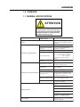
1
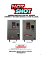
INSTANTANEOUS WATER HEATER
INSTRUCTION AND INSTALLATION MANUAL
3-48 kW
54-144 kW
YOUR DISTRIBUTOR: Chemical Distributors, Inc.
PHONE: 716-856-2300 • 800-777-2436 • FAX: 716-856-7115
80 Metcalfe Street • BUFFALO, NEW YORK 14206 U.S.A.
[email protected]
www.cdibuffalo.com
1
YOUR DISTRIBUTOR: Chemical Distributors, Inc.
80 Metcalfe Street
Buffalo, NY 14206
PH: 716-856-2300
www.cdibuffalo.com
©
COPYRIGHT 2001 Process Technology, Inc.
All rights reserved. Any reprinting or unauthorized use without written permission of
Process Technology, Inc. is expressly prohibited.
The information in this manual has been carefully checked and is believed to be accurate; however, no
responsibility is assumed for omissions or inaccuracies.
All information in this document is subject to change without notice.
This document contains proprietary information and is subject to the conditions that the information:
♦ Be retained in confidence.
♦ Not be reproduced or copied in whole or in part.
♦ Not be used or incorporated as part of any product except under an express written agreement
with Process Technology, Inc.
This document is available on cleanroom paper. Contact Process Technology Inc. to order
place HCT specific label here
2
PREFACE
SAFETY SYMBOLS AND THEIR DEFINITIONS
Take time to review these symbols and their meaning. They are used
throughout this manual to serve as a notification of potential hazards, damage and/or injury. While the notification cannot eliminate
a hazard, a considered understanding of a specific hazard and a
proper course of associated activity will assist in improving accident prevention.
DANGER
Used to indicate an imminent hazardous
situation which, if not avoided, will result
in death or serious injury.
DANGER SYMBOL
WARNING
Used to indicate a potentially hazardous
situation which, if not avoided, could result
in death or serious injury.
WARNING SYMBOL
3
PREFACE
CAUTION
Used to indicate a potentially hazardous
situation which, if not avoided, may result
in injury, or an alert against an unsafe
practice.
CAUTION SYMBOL
ATTENTION
Used to direct operating or installation
personnel to a correct course of action.
ATTENTION SYMBOL
4
PREFACE
RELATED DOCUMENTS
The following documents are to be used in conjunction with this manual:
ANSI/NFPA 70 - National Electric Code®, latest edition. To be used in
conjunction with electrical service, wire sizing, routing and protection.
SEMI S2 - Semiconductor Equipment Safety Guideline, latest edition. To
be used in conjunction with safe operation, access and decommissioning
procedures.
DSL Instruction Manual, latest edition.
To be used in conjunction with accessible features of the DSL temperature
control. (Secure appropriate manual for any optional temperature control
used in place of the DSL.)
ANY state or local building codes that would cover the electrical,
mechanical or physical installation of electric heating equipment.
National Electric Code®
NFPA 1999 Copyright
National Fire Protection Association
Quincy, Mass. 02269
5
PREFACE
LIST OF ILLUSTRATIONS
Overall View of the H2OT SHOT..................................................cover
System Nameplate...........................................................................7
Heating Element Cutaway..................................................................10
Solid State Relays............................................................................11
View of the H2OT SHOTs.................................................................12
DSL Control...................................................................................... 13
Differential Pressure Switch............................................................13
Cool Down Solenoid........................................................................ 13
Mounting Hole Locations
3 element HCT.......................................................................15
9 element HCT.......................................................................15
Orifice Assembly..............................................................................18
Plumbing Connections.......................................................................19
Circuit Breaker...................................................................................20
DSL Functions...................................................................................22
System Front Panel.........................................................................22
Control Terminal Block......................................................................31
Differential Pressure Switch Adjustment.........................................31
Orifice Assembly................................................................................32
Orifice Assembly Supply Side..........................................................32
Orifice Assembly Outlet Side...........................................................32
Orifice Plate.......................................................................................32
O-rings................................................................................................32
GFP Test Button..............................................................................34
Duplex Filter (Strainer) Layout.........................................................36
3 element HCT Components...........................................................37
9 element HCT Components...........................................................38
6
RECEIVING INSPECTION
It is imperative that the H2OT SHOT be examined for any shipping damage
upon receipt. Although the typical damage may be “shake loose” damage
only, any significant structural damage must be noted with the delivering
carrier, as expensive and time consuming remedies may result.
Verify that the unit specifications, found on the H2OT SHOT data tag (see illustration on left) agree with your purchase order. Any discrepancies should be brought
to the attention of your purchasing department for immediate correction.
If problems are encountered with the H2OT SHOT, verify that all applicable
instructions have been followed properly and that they are consistent with
the application and operating parameters.
SYSTEM NAMEPLATE
CONTACTING PROCESS TECHNOLOGY
If problems persist, call Process Technology for technical assistance at (800)
621-1998 (U.S./Canada), or (440) 946-9500 (Outside U.S./Canada). Have
the following information available:
♦
Model Number
♦
Serial Number
♦
Detailed description of the problem
♦
Application specifics such as: flow rates, inlet and outlet
temperatures, and cycle times
A Technical Sales staff member will analyze the problem and provide a course
of action to return the unit to operation. If, after analyzing the problem an
acceptable solution cannot be implemented, or if the repairs require factory
attention, the Tech Sales staff member will issue a Return Material Authorization (RMA) number. The RMA number is for the return and evaluation of the
H2OT SHOT or suspect component(s). Display this RMA number on the outside of the shipping container when returning to Process Technology. Every
effort is made to evaluate returned H2OT SHOTs within 24 hours of receipt.
Items returned to Process Technology for any reason SHALL BE VIA
FREIGHT PREPAID, unless alternate, prior arrangements have been made.
All materials must be cleaned and neutralized to remove all traces of any
chemical deposit. The identity of any substance used in the H2OT SHOT
must be divulged, and corresponding material safety data sheets (MSDS)
must be returned with the unit.
A H2OT SHOT needing to be returned must be sent to Process Technology’s
Mentor, Ohio, USA location:
Process Technology, Inc.
7010 Lindsay Drive
Mentor, OH 44060 USA
Re: RMA#
7
CONTENTS
PREFACE
Safety Symbols and Their Definitions...................................... 3
List of Related Documents........................................................ 5
List of Illustrations... ................................................................... 6
Receiving Inspection....................................................................7
Contacting Process Technology...................................7
1.0 Overview
1.1 General Specifications....................................................... 9
1.2 Principles of Operation.......................................................10
1.3 Controls and Safeties..........................................................13
2.0 Installation
2.1
2.2
2.3
2.4
2.5
Mounting...............................................................................14
Tightening Torques..............................................................16
Mechanical...........................................................................16
Electrical...............................................................................19
PreStart Testing...................................................................21
3.0 Operation
3.1
3.2
3.3
3.4
3.5
Description of Controls......................................................22
Start Up.................................................................................24
Shutdown.............................................................................25
Alarm/Fault Conditions.......................................................25
Non Alarm Conditions.......................................................25
4.0 Troubleshooting
4.1 System Not Heating............................................................26
4.2 Heating Element................................................................27
4.3 Solid State Relay................................................................28
4.4 DSL Output Signal.............................................................29
4.5 Continual Overheating.......................................................30
5.0 Maintenance
5.1
5.2
5.3
5.4
Adjusting the Differential Pressure Switch......................31
Changing the Orifice Plate................................................32
Testing the GFP...................................................................33
Heating Elements...............................................................34
6.0 Components
6.1 3 and 9 Element HCTs.......................................................37
Spare Parts.....................................................................................39
Index....................................................................................................40
8
OVERVIEW
1.0 OVERVIEW
1.1 GENERAL SPECIFICATIONS
ATTENTION
This user’s manual provides information
necessary for the correct and safe operation of the Process Technology H2OT SHOT.
Compliance failure can result in property
damage and personnel injury.
Model
Electric Instantaneous
Water H eater
H 2OT SH OT ((H
Se
HC
CT
Sreie
rs
i e) s )
In-li ne heater for si ngle pass
systems wi th reci rculati ng opti ons
avai lable
System
Heater Power
3-144 kW
Temperature Regulati ng
Accuracy
±1°F (±1°C ), dependent upon
operati ng condi ti ons
Temperature Li mi t
185°F (85°C )
Flow Rate Ranges
3 - 48 kW Models: 1-15 gpm
(3.8 - 57 lpm)
54 - 144 kW Models: 4-17 gpm
(15 - 64 lpm)
For hi gher flow rates consult
factory.
Maxi mum Operati ng
Pressure
100 psi g (7030 g/cm3)
Temperature C ontroller
Mi cro-processor based PID
controller, factory pre-set
Fi ri ng C i rcui t
Zero cross, burst fi red, soli d state
relays (SSRs)
Temperature Sensor
Type J thermocouple
Heati ng Element
Ti tani um tubular heati ng elements
i nsi de ti tani um contai nment tube
(Stai nless Steel constructi on also
avai lable, consult factory)
Materi al of Wetted Parts
Grade 2 C P ti tani um, PVD F, FEP,
Vi ton, T316 Stai nless Steel
Inlet/Outlet C onnecti ons
¾” MNPT standard, custom
connecti ons avai lable
Performance Specifications
C omponents and C onstruction
Emergency Operator Stop Swi tch
(EMO)
Hi gh process temperature alarm
Safety Functions
Low flow heater cutout
Element sheath overtemp
thermostats
Mai n ci rcui t breaker; GFP
standard on 3-48kW models,
opti onal on 54-144kW models
Pow er Supply
208-600 VAC , 3F (1F and custom
voltages avai lable)
9
OVERVIEW
1.2 PRINCIPLES OF OPERATION
The H2OT SHOT is a uniquely designed, compact, self-contained unit that
heats water or process chemistry on demand. It is specifically designed
to minimize fluid holdup volume and provide a clean, non-contaminating
flow path for high purity processes.
Titanium Outer C ontainm ent Shell
H igh Velocity, Low Volum e
W ater C h am ber
Titanium Tubular
H igh Energy
H eating E lem ents
C utaw ay View of H eating Elem ent
The low volum e of w ater heated by the H igh Energy elem ents
requires a reliable inlet water supply at all tim es.
10
OVERVIEW
When properly installed, the H2OT SHOT senses flow rate using a differential pressure switch to sense the presence of a pressure drop across an
orifice plate. When the preset pressure drop is reached, the heater firing
circuit is enabled, allowing the heaters to energize. As the fluid travels
through the outer containment shell (approx. 118 inches [3 m] in length), it is
heated to the desired heat setting. Small differences in flow rate that could
change the outlet temperature are regulated to within +/- 1° F (+/- 0.5°C) by
the DSL temperature controller.
Whenever the flow rate falls below the preset minimum, the H2OT SHOT
switches to a standby mode and a small amount of fluid is discharged to a
drain to permit the heating elements to cool down.
WATER COOLED SSRs
WARNING
Shutting off water flow to the H2OT SHOT while
in operation prevents element cool down and
creates a super heated steam in the heating
element. Customer fitting failure and damage
to the solid state relays may result.
At the end of this cool down cycle, the H2OT SHOT switches to a standby
mode until the design flow rate is achieved and the heating mode is
started.
With multiple flow rate models, multiple pressure switches or a precision
differential pressure transducer with appropriate signal conditioners are
used to detect 2 or more flow rates and a below minimum flow rate to
initiate the cool down cycle.
AIR COOLED SSRs
The basic H2OT SHOT incorporates 3 tubular heating elements while
larger versions have 9 elements. Single element models are used where
low flow rates (less than 1 GPM/4 LPM) are required. In special applications, a basic H2OT SHOT can be coupled to a single element model to
accommodate very low and/or high flows.
Solid state relays regulate the power level to the H2OT SHOT and are
normally water-cooled. Air-cooled SSRs are necessary whenever the
inlet fluid temperature exceeds 90° F.
11
OVERVIEW
H2OT SHOT models 3-48 kW are comprised of 2 enclosures, one on top
of the other. The upper enclosure is the control module and houses the
majority of the electrical components.
3-48 kW H2OT SHOT
H2OT SHOT models 54-144 kW are comprised of 2 enclosures, one
behind the other, connected with a hinge. The front enclosure is the
control module and houses the majority of the electrical components.
54-144 kW H2OT SHOT
12
OVERVIEW
1.3 CONTROLS AND SAFETIES
TEMPERATURE
CONTROLLER
The control of the H2OT SHOT resides in two components, the DSL
temperature controller and the differential pressure switch (or the alternate flow detection method). The temperature controller senses the outlet
temperature, compares that value to the set point and adjusts the firing
rate of the solid state relays to provide the required power level to
achieve (maintain) the required temperature. The DSL control also
contains the high temperature alarm set point. This is factory set for
safety. If the outlet temperature exceeds the factory set point, the main
heating contactor will open, removing heating power and sounding the
alarm.
The differential pressure switch senses pressure drop (which is proportional to flow rate) across a specified orifice plate. When the pressure
drop (flow rate) achieves a predetermined level, power is applied to the
heating elements via the solid state relays. When the pressure drop (flow
rate) falls below this predetermined level, power to the solid state relays
is removed and a timed cool down cycle is initiated. The cool down cycle
consists of approximately 1 gallon (3-4 liters) of water flowing through the
cool down solenoid to a suitable drain site.
COOL DOWN
SOLENOID VALVE
The cool down solenoid is also actuated if the outlet temperature sensed
by the DSL control exceeds the set point value by 10° F (5° C). This
feature moderates the outlet temperature in a momentary low flow
condition.
Situated on the H2OT SHOT heating element are three bimetallic overtemperature safety switches. If the heating element exceeds the factory
set point, the main heating contactor will open, removing power and
sounding the alarm.
DIFFERENTIAL
PRESSURE SWITCH
Most H2OT SHOTs are equipped with electrical ground fault protection
(GFP). A typical mode of failure for electric heating elements is shorting
to ground. If the GFP detects a fault leakage, it will open the main circuit
breaker or main heating contactor.
T
D A N GER
The H 2OT SH OT ground fault circuitry
(GFP) is for detection of heater element
failure ON LY. The GFP will N OT afford
shock protection for personnel.
13
INSTALLATION
2.0 INSTALLATION
2.1 MOUNTING
On H2OT SHOT models 3-48 kW, mounting holes are located on the rear
panels of the upper and lower enclosures.
♦ Do not install the unit in an atmosphere where it will be exposed to
corrosive gases, explosive vapors, temperatures above 104° F (40°
C), or humidity above 90% (non-condensing).
♦ Ample clearance must be provided around the H2OT SHOT in the
event that service or maintenance must be performed. Due to the
need for a drain for the cool down cycle, fluids may require special
disposal methods which may affect placement of the unit.
♦ Examine your proposed mounting surface and assure that it is capable of supporting the weights indicated for the H2OT SHOT.
55 lbs. (25 kG) for H2OT SHOT 3-48 kW
110 lbs (50 kG) for H2OT SHOT 54-144 kW
Access to the interior of the upper and lower H2OT SHOT enclosures is
gained by rotating the circuit breaker (or disconnect) handles counterclockwise slightly past the OFF position and turning each of the cover
latches 1/4 revolution with a flat-bladed screwdriver. Mounting holes are
located at the extreme corners.
On H2OT SHOT models 54-144 kW, mounting holes are located in the
rear enclosure. The front enclosure is accessed by rotating the circuit
breaker handle slightly past the OFF position and turning each of the
cover latches 1/4 revolution with a flat-bladed screwdriver.
To access the rear enclosure, insert a flat bladed screw driver into the
release latch located on the right side of the internal electrical panel and
swing the electrical panel outward.
Power connections are made to the rear enclosure via an umbilical cord
that exits through the back of the control module. Care should be taken to
avoid damaging this umbilical cord. Note the mounting bolt hole locations
on the back panel. These will be used to locate and secure the H2OT
SHOT to a surface capable of supporting the weight of the specific
model.
14
INSTALLATION
0 .5 " (1 3 m m )
4 p laces
1 8 .5 "
470 m m
1 8 .5 "
470 m m
3 0 .6 3 "
778 m m
3-48 kW UNITS
2 8 .5 "
724 m m
54-144 kW UNITS
MOUNTING DIMENSIONS
Measure the four mounting hole locations on the H2OT SHOT rear panel
and transfer these positions onto your mounting surface. Four 3/8" (10
mm) bolts are sufficient for structural support, provided it is mounted on a
suitable structure.
If the mounting surface is masonry, properly installed masonry anchors
can be utilized. If you are unsure of the strenght of the masonry, use
through-bolting with backing plates. Consult your local masonry contractor for assistance.
Structural frameworks should utilize through-bolting (as opposed to
tapped holes) .
Once the H2OT SHOT is securely fastened to the mounting surface, carefully inspect for any loose wiring or loosened power terminal connections.
Shake-loose damage may occur when the H2OT SHOT is subject ed to
excessive vibration during transit.
Electrical connections must be checked to ensure that the required
tightening torque is still applied.
15
INSTALLATION
2.2 TIGHTENING TORQUES
WARNING
Improperly torqued electrical terminal
connections will result in overheating
and may result in a fire.
TIGHTENING TORQUE FOR ELECTRICAL CONNECTIONS
Contactors
see data on contactor tag
Heater Fuses
84 IN-LBS (9.5 Nm)
Circuit Breaker
see data on circuit breaker tag
Power Terminal Blocks (white)
50 IN-LBS (5.6 Nm)
Power Terminal Blocks (black)
see data on terminal block body
Once you arer assured that all of the terminals are properly torqued and
that no loose wires (or parts) exist, proceed with the installation.
2.3 MECHANICAL
The H2OT SHOT must never be used with flammable liquids.
D A N GER
The heating elements are capable of
reaching a temperature in excess of
1385° F (750° C ) which may exceed the
auto ignition temperature of many fluids
and combustible materials.
16
INSTALLATION
Flammable liquids may be heated indirectly using the H2OT SHOT in a
closed loop system with an appropriate thermal transfer fluid and heat
exchanger system. Consult the Technical Sales department at Process
Technology if questions arise regarding the suitability of fluids for use in
the H2OT SHOT.
The H2OT SHOT requires a consistent minimum flow. That flow is determined by using the formula below. This value is also printed on the
faceplate of the unit. Failure to supply sufficient flow may cause permanent damage to the equipment.
6.80 x (kW rating of water heater)
Minimum gpm = ——————————————————(180-maximum inlet water temperature °F)
-orkW rating of water heater
Minimum lpm = ——————————————————(82-maximum inlet water temperature °C)
WARNING
Shutting off water flow to the H2OT SHOT while
in operation prevents element cool down and
creates a super heated steam in the heating
element. Customer fitting failure and damage
to the solid state relays may result.
All flow control valves must be installed on the outlet side of the H2OT
SHOT to ensure that the heater has full pressure and flow available at all
times. Restricting flow on the inlet side of the heater will cause serious
damage to the heating elements.
A service valve on the inlet side of the unit should be installed and clearly
labeled:
“FOR SERVICE ONLY”
17
INSTALLATION
The inlet water temperature to the H2OT SHOT must not exceed 90° F (32°
C) unless the unit is equipped with optional air-cooled solid state relays.
All plumbing must be designed to withstand an over-temperature event (>212°
F/100° C), plus any safety factor specified by your system designer. Low
temperature thermoplastic piping must NOT be used. Piping of titanium,
stainless steel, PVDF, or PFA may be used at inlet and outlet connections.
The H2OT SHOT is supplied with 3/4” MNPT fittings for inlet and outlet connections as standard.
A minimum pipe size of 1/2” (13 mm) is recommended for flow rates up to 5
gpm (19 lpm). Unions or flange fittings are recommended to expedite removal for maintenance.
ORIFICE ASSEMBLY
The direction of flow through the H2OT SHOT is critical for proper performance.
Refer to the indicating arrows on the heating element for proper flow direction.
In the absence of the indicating arrows, you can determine the OUTLET connection by locating the ORIFICE ASSEMBLY. It is always located on the OUTLET side of the H2OT SHOT.
Fluoropolymer tape is suggested as a pipe thread sealant. Clay-based pipe
dope is not an acceptable sealant.
Care must be exercised when engaging threaded fittings to the heater, as
excessive torque can cause damage to the heater. Always secure the heater
side nipple with a pipe wrench. Position this opposite to the tightening wrench
in order to prevent tightening torque from being transferred to the heater.
A 1/4” (6.35 mm) stainless steel compression fitting is supplied for connection to the cool down (bleed) system. Install 1/4” stainless steel tubing from
this fitting to a zero back pressure disposal drain.
The temperature of this cool down fluid will often exceed 100° C. Adjoining
pipe materials must be able to withstand these temperatures.
ATTENTION
Cool down fluid temperature can
exceed 100° C.
18
INSTALLATION
After piping installation, it is recommended that the installed piping and
the heater be thoroughly flushed with DI water to remove any contaminants that were introduced during installation.
Inlet
O utlet
C oo l D ow n O u tlet
Plum bing C onnections
2.4 ELECTRICAL
It is recommended that a service disconnect be installed ahead of the
H2OT SHOT.
Verify that the voltage and service specified on the data tag meets your
specifications.
Survey the power line for transient energy and harmonic distortions that
can be caused by phase angle firing circuits, electromagnetic interference (EMI) and radio frequency interference (RFI). These sources of
interference can cause erratic control and premature solid state relay
failures. Either correct the cause or provide line filters to minimize any
power distortions.
All H2OT SHOTs are energized and tested in the factory prior to shipment.
The end user is responsible for the proper wiring of the unit.
The National Electric Code (NEC), state, local, and other applicable
codes must be followed. The recommendations which follow are not to
conflict with the NEC or any other applicable code, but are to be a guide
for field wiring of the H2OT SHOT.
ONLY QUALIFIED ELECTRICIANS SHOULD BE PERMITTED TO
PERFORM THE INSTALLATION
19
INSTALLATION
DANGER
The H2OT SHOT operates at voltages
hazardous to personnel. Accidental or
purposeful circuit energizing without
proper precautions can be lethal.
Copper wire rated for 75° C should be used for power connection between
the service disconnect and the circuit breaker. Refer to the NEC, Table
310-16, for appropriate wire sizing.
CIRCUIT BREAKER
AND GFP
Stranded wire and compression lugs are recommended for ease of installation and to minimize destructive heating that can occur when the connection torque loosens over time.
Gasketed conduit connections and junction boxes are recommended to
protect the H2OT SHOT from vapors, sprays, or drips.
Flexible conduit or a jointed conduit must be used on 54-144 kW H2OT SHOT
models due to the need for access to the heater module. Be certain to allow
enough conduit and wire for a 90° opening of the control module.
IEEE grounding recommendations should be followed, i.e. both a metal
conduit/raceway and a “green ground wire” be installed. Verify ground impedance per NEC Sec. 250-84.
With the above installation instruction completed, the H2OT SHOT is ready
for initial start-up procedures.
20
INSTALLATION
2.5 PRE-START TESTING
Prior to placing any H2OT SHOT into operation preform the following:
♦
♦
♦
♦
♦
Verify electrical voltage.
Verify water source pressure and flow rate.
Verify destination piping.
With power disconnected at the service disconnect and the H2OT
SHOT enclosure open, open the flow control valve and allow water
to flow through the heater. Crackling and popping noises are an
indication that trapped air is being flushed out of the unit. Cycle the
flow off and on several times to remove all air from the heater. Close
the outlet flow control valve to pressurize the unit. Verify that no
leaks exist.
Close the H2OT SHOT enclosure.
DANGER
The H2OT SHOT operates at voltages
hazardous to personnel. Accidental or
purposeful circuit energizing without
proper precautions or with enclosure
open can be lethal.
♦
♦
With the circuit breaker and the power toggle switch OFF, turn ON
the service disconnect. Turn ON the circuit breaker. Turn ON the
power toggle switch. The audible alarm will annunciate and the
power-on and safety-on lights will be illuminated.
Depress the start/reset push button and verify that the audible
alarm is silenced.
TURN OFF POWER AT THE POWER TOGGLE SWITCH, CIRCUIT
BREAKER AND SERVICE DISCONNECT
The above procedure verifies the serviceability of the installation.
21
INSTALLATION
3.0 OPERATION
3.1 DESCRIPTION OF CONTROLS
DSL CONTROLLER
A ud ib le A larm
C ircu it B re aker
D is co n n e ct H a n d le
P o w er To g g le sw itch
S ta rt/R e s e t
E m erg en cy S top b u tton
SYSTEM FRONT PANEL
22
OPERATION
DSL CONTROL Displays: current outlet temperature PV-upper display;
set point value SV-lower display; displayed temperature units °F or °C;
power applied Set Point 1 Lamp; over-temperature alarm Alarm Lamp;
plus access to review or change factory settings (refer to DSL Manual
provided separately).
AUDIBLE ALARM HORN Annunciates whenever the H2OT SHOT
power contactor is open. Requires a START/RESET action on initial
start up, or a corrective action followed by a START/RESET (following
any alarm condition).
HEATER/ON LAMP When illuminated, indicates that the differential
pressure switch senses a flow rate above the preset minimum and the
heater firing circuit is active.
SAFETY/ON LAMP When illuminated, indicates that the safety circuit is
in the normal condition. The emergency stop switch, element overtemperature sensors, and high temperature alarm are in their normal
states.
POWER/ON LAMP When illuminated, indicates that the control circuitry
is energized.
START/RESET BUTTON When depressed, places the unit in operation. Silences the alarm upon start-up.
EMERGENCY STOP BUTTON When depressed, disables heater
power circuits.
POWER TOGGLE SWITCH Turns control power off or on.
NEVER OPEN THE H2OT SHOT ENCLOSURE WITH POWER
APPLIED TO THE UNIT. DISCONNECT POWER TO THE UNIT
BEFORE INSPECTION OR PERFORMING ANY SERVICE.
23
OPERATION
3.2 START UP
♦
♦
♦
♦
♦
♦
♦
Verify that the power toggle switch is in the OFF position.
Verify that the circuit breaker is in the OFF position.
Turn the service disconnect ON.
Turn the circuit breaker ON.
The digital temperature controller (DSL) will perform a brief self-test,
then display the current outlet temperature (PV) and setpoint (SV) value.
The PV displayed is sensed via a thermocouple located at the outlet of
the H2OT SHOT. Adjustment of SV (SP1) can be made at this point.
(For information on how to adjust SP1 or any other DSL settings, refer
to the enclosed DSL Instruction Manual.) All other DSL settings are
factory preset. Individuals unfamiliar with the programming of proportional-integral-differential (PID) temperature controllers should consult
the Tech Sales staff at Process Technology for assistance in altering
the programming of the DSL.
Turn the power toggle switch ON. This will cause annunciation of
the audible alarm, signifying that the system requires manual
reset. The power-on and safety-on lights will be illuminated.
Depress the green start/reset button. This will silence the alarm
and place the H2OT SHOT in standby mode. The bleed cycle will
also be initiated for 30 to 60 seconds.
At any point after placing the H2OT SHOT into standby mode, the flow control valve may be opened. When water flow above the preset minimum is
detected, the heater will be enabled. This event is signified by illumination
of the heater-on light. At this point, the heater is under the control of the
DSL, and will heat water as required.
The heater subassembly is under pressure during operation and is extremely
hot. In some applications this can mean hot corrosive fluids. Always wear
protective equipment described in the MSDS for the particular chemistry
circulating in the H2OT SHOT when performing maintenance. In addition,
always wear additional thermal protection to minimize the potential of sustaining burns or other injuries.
When the outlet flow control valve is closed, or the flow rate falls below the
preset minimum, the cool down cycle is initiated. The H2OT SHOT then reverts to standby mode. The cool down cycle can be interrupted and the heater
re-enabled by increasing the flow rate to a level above the preset minimum.
24
OPERATION
3.3 SHUTDOWN
Shut down of the H2OT SHOT must be accomplished by closing the outlet
valve. This initiates the cool down cycle and cools the heating element.
Once the cycle has timed out (allow 60 seconds):
♦
♦
Turn the power toggle switch OFF.
Turn the circuit breaker OFF.
3.4 ALARM/FAULT CONDITIONS
The following conditions constitute alarm or fault conditions with the H2OT
SHOT and are accompanied by annunciation of the audible alarm; requiring corrective action and manual reset:
♦
♦
♦
High Solution Temperature -disables heating circuit when outlet
temperature exceeds the preset DSL Alarm setting. This is
usually caused by cyclic low flow conditions. Verify the reliability
of water source.
Heating Element Case Over-temperature - disables heating circuit
when bimetallic temperature sensors, located on the outside of
the heater subassembly, detect abnormally high surface
temperature. Can be caused by sustained insufficient flow
condition or mineral buildup on the heating elements.
Emergency Stop - disables heating circuit when the emergency
stop button is depressed.
3.5 NON ALARM CONDITIONS
♦
Ground Fault - circuit breaker is tripped in the event of a ground
fault in the heating element or control circuitry. Unless nuisance
tripping is suspected, this event may indicate heater failure. See
the Maintenance Section of this manual.
DANGER
The H2OT SHOT ground fault circuitry
(GFP) is for detection of heater element
failure ONLY. The GFP will NOT afford
shock protection for personnel.
♦
DSL Error Messages - refer to the DSL Instruction Manual for an
explanation of the various error messages.
25
TROUBLESHOOTING
4.0
TROUBLESHOOTING
4.1
SYSTEM NOT HEATING
Check to ensure that the service disconnect and the H2OT SHOT circuit
breaker is ON.
Is The DSL display ON?
If not, is the circuit breaker in the ON position?
If not, reset the ground fault protector (GFP).
If not, check control fuses.
Is The DSL set point value (lower display)
higher than the outlet temperature (upper
display)?
If not, program the correct set point (SP1) value.
Is The DSL alarm lamp illuminated?
If so, wait for the lamp to extinguish and reset the
H2OT SHOT.
Is The DSL set point lamp 1 illuminated?
This is normal, continue with troubleshooting.
Is The DSL set point 2 lamp illuminated?
This may be normal. The lamp should extinguish in a
few seconds.
Is the power/on lamp illuminated?
If so, this is normal.
If not, turn the power toggle switch ON.
Is the safety/on lamp illuminated?
If so, this is normal.
If not, press the start/reset button.
Is the heater/on lamp illuminated?
If so, this is normal.
If not, check water flow rate and increase to minimum
flow requirement.
Is the audible alarm sounding?
If so, press the start/reset button.
If alarm continues, allow sufficient time to permit
possible heating element overheat to cool.
If after 20-30 minutes attempts at reset still fail,
contact Technical Sales for assistance.
26
TROUBLESHOOTING
DANGER
The H2OT SHOT operates at voltages
hazardous to personnel. Accidental or
purposeful circuit energizing without
proper precautions can be lethal.
If all of the above appear normal and the H2OT SHOT is NOT heating,
there is the possibility of damage to:
♦
♦
♦
The DSL output signal,
The solid state relays (SSRs), and/or
The heating elements.
Investigation of any of the above possibilities requires a qualified electrician since checking procedures will require energizing of components
with an open enclosure.
4.2 HEATING ELEMENTS
The heating elements can be checked by verifying the full load current
values on all three phase legs.
With power OFF at the disconnect and circuit breaker, open the enclosure to access the incoming power lines.
Using a clamp-on AC amp meter, clamp around one of the incoming
power wires. Restore power and flow rate. Reset H2OT SHOT controls
and verify that all indicators are normal.
Observe the amp meter and compare the reading with the AMPS indicated on the data tag.
Repeat this procedure on each of the three incoming power wires.
A value +/- 10% of the data tag value is considered acceptable.
Any value above or below this range is considered unacceptable. Consult Tech Sales for further assistance.
27
TROUBLESHOOTING
4.3 SOLID STATE RELAYS
The solid state relays (SSRs) can be damaged by transients on the incoming lines or overheating. The mode of failure can be shorted or open with
the H2OT SHOT symptoms being always heating/overheating or no heating
respectively.
Check the solid state relays as follows:
♦
Turn OFF power at the service disconnect and the H2OT SHOT
circuit breaker.
♦
Open the heating enclosure and locate the solid state relays .
♦
Secure these connections as necessary and restore power to the
H2OT SHOT.
♦
Proceed with a normal start-up routine observing the front panel
control indicators.
If all indicators are normal, observe your digital multimeter readings.
Variations of -5 to 10% of the nominal line voltage are considered acceptable. Over -10% or NO voltage indicates the solid state relay has
failed open.
If above appears nominal, slowly reduce the flow rate by throttling the
outlet control valve. If the cool down cycle initiates and the multimeter
indicates NO drop in line voltage (~0 VAC), the solid state relay has
failed shorted.
If all of the above appears nominal, repeat this procedure on each of the
other solid state relays.
Any reading outside of those described may require replacement of the
SSRs. Solid state relay replacement requires special installation considerations, call Technical Sales for detailed replacement instructions.
28
TROUBLESHOOTING
4.4 DSL OUTPUT SIGNAL
Dependent upon the specifications of the H2OT SHOT provided, the DSL
control will either provide a voltage or current output signal to control the
heating cycle.
The output signal is either 15 VDC or 4-20 DCmA. Refer to the supplied
electrical wiring diagram for output provided.
Check the output signal as follows:
♦ Turn OFF power at the service disconnect and the H2OT SHOT
circuit breaker.
♦ Open the enclosure and locate the DSL rear terminals.
For 15 VDC output:
♦ Connect your digital multimeter’s positive voltage probe to terminal 15
and the negative voltage probe to terminal 16.
For 4-20 DCmA output:
♦ Disconnect the wires attached to terminals 15 & 16 and install the
negative mA probe from your digital multimeter to terminal 15. Install a
~560 ohm resistor* on terminal 16, attaching the positive mA probe to the
other end.
*Radio Shack Cat. No. 271-1116
♦ Secure these connections as necessary and restore power to the
H2OT SHOT.
IT IS NOT NECESSARY TO TURN ON THE POWER TOGGLE
SWITCH OR ATTEMPT ANY OTHER RESETS FOR THIS CHECK.
Observe that the DSL set point 1 lamp is illuminated and that your digital
meter values read +/- 5% of either the 15 VDC or 4-20 DCmA signals.
Values outside of this range are unacceptable and may require replacement of the DSL control. Contact the Process Technology Technical Sales
Department for assistance.
29
TROUBLESHOOTING
4.5 CONTINUAL OVERHEATING
The usual cause of continual overheating is low water flow rate. Before
preforming any electrical checks verify that the flow rate is ALWAYS
above the minimum operating flow rate. This value is indicated on the
cabinet data plate. Frequent flow interruptions or reductions will place the
H2OT SHOT in an alarm mode. If flow is insufficient to permit adequate
cooling, an overheat condition will result.
Investigate the system water demand for sufficient pipe sizes and routing.
Provide increased flow or, if momentary demands are causative, booster
pump and captive air tank to correct. If pipe size or routing is causatively,
re-pipe to suit.
REPEATED LOW FLOW EVENTS WILL DAMAGE THE H2OT SHOT.
Flow rates are also diminished due to internal element fouling (scaling) or
plugging. Refer to the section on Maintenance Heating Elements for
corrective action.
Shorted solid state relays can cause continual overheating. Refer to the
previous section on Troubleshooting Solid State Relays. Another cause
can be the drifting of the differential pressure switch settings or failed
differential pressure switch. Refer to the next section for adjustment
procedures.
30
MAINTENANCE
5.0 MAINTENANCE
5.1 ADJUSTING THE DIFFERENTIAL PRESSURE
SWITCH
If the differential pressure switch needs adjustment due to changes in the
process characteristics, contact the Technical Sales staff at Process
Technology for authorization, since flow rates more than 10% lower than
the factory settings can pose the possibility of heating element damage.
If instructed to perform adjustments, proceed as follows:
Disconnect power to the H2OT SHOT and turn off flow through the unit.
CONTROL
TERMINAL BLOCK
Attach a continuity tester across the common (COM) and normally open
(N/O) terminals of the switch. Refer to the wiring diagram, included with
the unit, for the identification of appropriate terminal block numbers.
Using a 3/16” wide slotted stubby screwdriver, turn the adjustment screw
on the side of the switch clockwise, until increased resistance is detected. Be certain to use a properly sized screwdriver, as the
adjustment screw is damaged easily.
DO NOT ADJUST THE INTERNAL HEX KEY SCREW LOCATED
ON THE WIRING SIDE OF THE SWITCH - THIS IS A FACTORY
CALIBRATED ADJUSTMENT!
Turn on flow to the unit. Set the flow rate to the desired level.
♦If continuity is not detected, slowly turn the adjustment screw on the
switch out (counter clockwise) until continuity is detected.
♦If continuity is continuous and the adjustment screw is in all the way,
there is too much differential pressure for the desired flow rate-orifice
combination. A larger orifice or a lower flow rate is required.
♦If no continuity is detected when the adjustment screw is all the way out,
there is not enough differential pressure for the desired flow rate-orifice
combination. A smaller orifice or higher flow rate is required.
If flow rate adjustment is NOT possible, see “CHANGING THE ORIFICE
PLATE” on the following page.
Cycle the flow off and on. There should be continuity only when flow is
present.
DIFFERENTIAL
PRESSURE
SWITCH
Close the enclosures and power-up the unit. Test the solenoid cool down
cycle.
31
MAINTENANCE
5.2 CHANGING THE ORIFICE PLATE
If the orifice plate needs replacement due to changes in process characteristics, contact the Technical Sales staff at Process Technology for
authorization, since flow rates more than 10% lower than the factory
settings can pose the possibility of heating element damage.
Once approval has been given and you are in possession of the replacement orifice plate, proceed as follows:
WARNING
Hot fluids and hot components are
possible. Allow sufficient time for cooling.
Wear protective gloves and face mask.
SUPPLY SIDE
Turn OFF power to the H2OT SHOT and turn off flow to the unit.
Disconnect the outlet plumbing from the unit, including blend/bypass
valve(s), if applicable.
Remove the four screws from the piping cover on the outlet side of the
heater. Remove the piping cover.
Using an open end wrench, hold the plastic tubing fitting extending from
the outlet assembly. Using another wrench, unscrew the compression
nut from the fitting. Remove the 1/4” tubing from the fitting. Unscrew the
fitting from the outlet side.
SEALS MADE
OF VITON®
OUTLET
SIDE
Using a 7/64” hex key, remove the two flange retaining bolts and nuts
through the bottom of the enclosure. With a twisting motion, remove the
outlet side downwards.
Remove the two o-rings and the orifice plate with a small pick or tweezers
from the outlet side. The o-rings should be replaced and the orifice plate
marked and set aside to minimize any confusion when reassembling the
orifice assembly.
ORIFICE PLATE
Lubricate the inside diameter of the orifice outlet and supply side with a
process compatible lubricant or mild hand soap.
Viton ® is a registered trademark of
DuPont Dow Elastomers.
32
MAINTENANCE
Insert the new orifice followed by insertion of new o-rings.
®
(O-rings are Viton AS568A-022)
With a twisting motion, replace the outlet side onto the supply side in the
same orientation as it was. The two flanges should meet flush. If unreasonable resistance is encountered, re-lubricate the mating parts and
verify the flat seating of the orifice plate and proper placement of the orings.
Reassemble the mounting bolts and nuts, and reconnect the tubing. Be
certain to hold any plastic compression fitting with a wrench while tightening the compression nut to avoid damage to the fitting.
Reattach the piping cover and the outlet plumbing.
Turn flow on and check for leaks. Adjust the differential pressure switch as
described on page 31 of this section.
Return the unit to service following the START UP guidelines.
5.3 TESTING THE GFP
The GFP (ground fault protector) should be tested on a monthly basis to
ensure reliable operation.
Turn OFF power at the service disconnect and the H2OT SHOT circuit
breaker.
Open the enclosure and locate the circuit breaker and GFP.
Restore power and depress the GFP Test Button.
All power should shut OFF. If not, replace GFP.
D A N GER
The H 2OT SH OT ground fault circuitry
(GFP) is for detection of heater element
failure ON LY. The GFP will N OT afford
shock protection for personnel.
33
MAINTENANCE
G F P Te s t B u tto n
CIRCUIT BREAKER
AND GFP
5.4 HEATING ELEMENTS
Mineral deposition or fouling inside the element will occur when the H2OT
SHOT is used in city water service or with any fluid source with minerals
and dissolved CO2 or organics. Frequent over-temperature events and
low flow rates compound this problem. It may be an indication that
mineral deposition or fouling is occurring if:
♦
♦
♦
♦
♦
♦
Reduced flow or no flow through the unit
Increased pressure drop across the unit
Failure to cool down at no or low flow conditions
dP switch setpoint shifts
Over-temperature alarms
Shortened element life
Blockage in the heating element may also be due to other sources such as:
♦
♦
♦
♦
♦
♦
Pipe dope compound from upstream plumbing repairs
Fluoropolymer pipe tape from upstream plumbing repairs
Resin beads from DI systems
Rust or scale from upstream piping
Restricted flow through an upstream filter
Particulate blockage from improper filter change-outs
34
MAINTENANCE
The recommended procedure for cleaning the heating element to remove
mineral deposits is to flush it with a compatible acid solution or other
scale remover. Low concentrations of nitric acid and proprietary buffered hydrochloric acid solutions have been used successfully at the
factory. Nitric acid removes deposits and passivates the titanium surfaces. Citric acid or commercial lime removers can be used as directed
by the manufacturer. DO NOT use any cleaner that contains hydrofluoric
acid, as titanium is aggressively attacked by fluorides.
To clean the heating element, power to the H2OT SHOT must be turned
off. The inlet and outlet should be disconnected. The orifice assembly
should be disassembled, the orifice plate removed, cleaned, and set
aside. Reassemble the orifice assembly without the orifice plate. A
polypropylene injector (Mazzei Injector Corp. model 484-A or equivalent),
connected to the inlet should be used to draw the cleansing agent into the
heater. Dispose of the wastewater properly. The time to thoroughly
clean the heating element will vary, depending on the cleaning agent used
and the amount of deposition. Restoration of the original pressure drop
at the specified flow rate indicates a clean heating element. The element
should be rinsed thoroughly and reassembled.
In situations where continued fouling is probable, a water conditioning
system should be installed upstream of the H2OT SHOT to remove or
sequester depositing minerals. It is the responsibility of the end user to
monitor and maintain the quality of any fluid used in the H2OT SHOT.
The recommended procedure for removing blockage is to reverse flush
through the H2OT SHOT as follows:
♦
♦
♦
♦
♦
♦
♦
♦
♦
Power to the H2OT SHOT must be turned off.
The inlet and outlet supply must be turned off.
Tag and remove all of the 1/4” tubing at the orifice assembly.
Remove the orifice plate as described on page 32.
Reassemble the orifice housing without the orifice plate.
Disconnect and plug (1/4” NPT plugs) the 1/4” tee and
straight fittings at the orifice assembly.
Disconnect the inlet and outlet piping.
Connect a high (up to 500 psig) pressure water source to
the outlet fitting.
Connect a temporary drain pipe to the inlet fitting.
35
MAINTENANCE
Direct the temporary drain to a barrel or bucket of known capacity. Determine the time required to fill this container initially. Continue to use this
container to “trap” any material that might have caused the blockage.
Using the high pressure water, reverse flush until an improved flow rate is
noted.
If the reverse flushing proves successful, reassemble the plumbing connections as follows:
♦
♦
♦
♦
♦
♦
Disconnect the reverse flushing source and move the
temporary drain to the outlet fitting.
Reconnect the inlet piping only.
Reinstall the orifice plate, as described on page 32.
Remove the plugs from the orifice housing and reconnect
the fittings.
Reconnect the tagged 1/4” tubing.
With the temporary drain in place, turn on the inlet water
supply and note the flow rate.
In situations where continued blockage is probable and service interruptions are unacceptable, a duplex filter or strainer system should be installed upstream of the H2OT SHOT to remove any particulates.
Install a 3-way inlet valve to eliminate the possibility of shutting off inlet
water to the H2OT SHOT during filter maintenance and creating a hazardous situation.
IN L E T
PRESSURE
GAUGE
W AT E R IN L E T
check valve
OUTLET
PRESSURE
GAUGE
W AT E R
F ILT E R
OUTLET
3 w ay valve
F ILT E R
check valve
WARNING
Shutting off water flow to the H2OT SHOT while
in operation prevents element cool down and
creates a super heated steam in the heating
element. Customer fitting failure and damage
to the solid state relays may result.
36
COMPONENTS
6.0 COMPONENTS
C ontrol R elays
Control
Transform er
M ain P ow er
Contactor
Circuit B reaker
& GFP
G FP coil
Control TBs
P o w er T B s
Fuses
3 ELEMENT HCT CONTROL COMPARTMENT
O vertem p erature S w itches
D isconnect Sw itch
Type "J" Therm ocouple
L e a d W ire
D ifferential Pressure Sw itch
Solenoid
G rounding Block
SSRs
O rifice A ssem bly
3 ELEMENT HCT HEATER COMPARTMENT
37
COMPONENTS
C ontrol R elays
C ircuit B reaker and G FP
C ontrol Fuses
Control
Transform er
R ear E nclosure
R e le as e Latch
m ain contactor
P o w e r Fu ses
9 ELEMENT HCT CONTROL COMPARTMENT
9 E lem ent
H C T C ontrol C om partm ent
overtem perature sw itches
differential pressure sw itch
control TB s
SSRs
orifice assem bly
solenoid valve
9 ELEMENT HCT HEATER COMPARTMENT
38
SPARE PARTS
SPARE PARTS
The following list of recommended spare parts was composed to assist
in maximizing “UP TIME” in the event of a component failure.
Factory ordered parts may be subject to stock outages.
Solenoid valve p/n____
Control Fuses p/n_____
Differential Pressure Switch p/n____
Solid State Relays p/n____
CONTACTING PROCESS TECHNOLOGY
If parts or service are required for the H2OT SHOT, contact Process Technology for technical assistance at (800) 621-1998 (U.S./Canada), or (440)
946-9500 (Outside U.S./Canada). Have the following information available:
♦ Model Number
♦ Serial Number
♦ Application specifics: parts needed, service required, etc.
A Technical Sales staff member will analyze your needs and provide a course
of action.
If the parts are considered under warranty or if the service repairs require
factory attention, the Product Support staff member will issue a Return Material Authorization (RMA) number for the return and evaluation of the H2OT
SHOT or suspect component(s). Display this RMA number on the outside
of the shipping container. Every effort is made to evaluate returned H2OT
SHOTs within 24 hours of receipt.
Items returned to Process Technology for any reason SHALL BE VIA
FREIGHT PREPAID, unless alternate, prior arrangements have been made.
All materials must be cleaned and neutralized to remove all traces of any
chemical deposit. The identity of any substance used in the H2OT SHOT
must be divulged, and corresponding material safety data sheets (MSDS)
must be returned with the unit.
Returned H2OT SHOTs must be returned to Process Technology’s Mentor,
Ohio, USA location:
Process Technology, Inc.
7010 Lindsay Drive
Mentor, OH 44060 USA
Re: RMA#
39