1
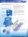
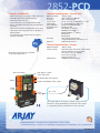
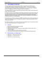
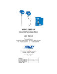
MODEL 2852-PCD Plugged Chute Detector User Manual Technical Support Continental North America Toll Free 1-(800) 387-9487 Ph: +1 (905) 829-2418 Fx: +1 (905) 829-4701 A Product of Arjay Engineering Ltd. Oakville, Ontario, Canada www.ArjayEng.com MODEL: HARDWARE NO.: SOFTWARE NO.: SERIAL NO.: 5.1 2852-PCD Plugged Chute Detector ENGINEERING Non-intrusive monitoring of chutes and hoppers for bulk material detection Over 40 years of capacitance experience stands behind the 2852-PCD plugged chute detectors. The flush mount sensor continuously monitors the change from a normal material chute condition to a plugged condition. Remote Electronics available in painted steel, SS or polycarbonate enclosure optional alarm light and/or buzzer up to 1 km • • • • capacitance technology responds to any material type no moving parts remote alarm unit mounts safely away from pipe no intrusion into chute or hopper The 2852-PCD sensor monitors the capacitance field in front of the sensor plate. The sensing plate forms part of the chute or hopper wall to sense the product within. The increased presence of product in front of the sensor due to a plugging condition increases the capacitance field and initiates an alarm. The sensing plates are embedded into a polyethylene plate which provides monitoring without any intrusion into the product flow. Optional Intrinsically Safe Sensor UHMWPE sensor face for erosion resistance non-intrusive monitoring of bulk product chutes and tanks 2852-PCD Features and Benefits Technical Specifications - Control Unit • flush mount sensor forms part of the chute wall • adjustable time delay and sensitivity to eliminate nuisance alarms • remote electronics via standard twisted pair • Sensor available Intrinsically Safe for Hazardous Locations • high erosion resistant polyethylene resists wear • capacitance technology responds to all types of bulk materials • non-intrusive sensor design does not restrict product movement Operating Temp. Resolution Accuracy Power Input Alarm Relay Analog Output Communication Certified -20˚C to +55˚C .007% (.07 pF at 1,000 pF) .04% of full scale pF 12 vdc or 24 vdc or 100-240 vac +/- 10% 2 x 10 amp@240 vac, SPDT, dry 4 mA normal/20 mA alarm Modbus RS-485 UL 61010-1, 2nd Edition CAN/CSA-22.2 61010-1-4 IEC/EN 61010-1, 2nd Edition IEC 61326-1 CE Declared Type 4 / IP 66 painted steel or Type 4X / IP 66 polycarbonate or SS Light, buzzer, beacon Enclosure Optional Technical Specifications - Sensor Operating Temp. Intrinsic Safety -60˚C to +55˚C CSA Intrinsically Safe when ordered with Approved Barrier in Control Unit Div 1, Class I, Groups A,B,C,D; Class II, Groups E,F,G; Class III, Encl.Type 4 UHMWPE (optional Teflon) Alternate probe designs are available for specialty applications. Wetted Parts Alarm and Status LCD display of alarm status and menus RS-485 Modbus user interface Relays 4 mA normal/20 mA alarm output Power input Probe input up to 1 km The unique PMC circuit design, installed at the probe and exclusive to Arjay, immediately converts the sensor signal to a frequency pulse for furtherance to the controller. ENGINEERING Arjay Engineering Ltd. http://www.arjayeng.com 2851 Brighton Road Oakville, Ontario telephone: ++1 905-829-2418 Canada L6H 6C9 N. America toll free: 1-800-387-9487 fax: ++1 905-829-4701 2852-PCD-12b Model: 2852-PCD User Manual TABLE OF CONTENTS 1.0 2.0 3.0 4.0 5.0 6.0 7.0 INSTRUMENT OVERVIEW ............................................................................................3 1.1 Features .............................................................................................................3 1.2 Model Number vs. Voltage Input........................................................................3 1.3 Specifications .....................................................................................................4 INSTALLATION...............................................................................................................6 2.1 Controller Installation .........................................................................................6 2.1.1 Permanent Power Connection (AC Powered Models only) ................6 2.2 Sensor Installation..............................................................................................7 2.3 Electrical Installation ..........................................................................................8 2.3.1 Input / Output Terminal Specification ..................................................9 2.4 Glossary of Symbols ..........................................................................................10 STARTUP AND CALIBRATION ......................................................................................11 3.1 Startup ................................................................................................................11 3.2 Menu Flow Chart Background Information ........................................................11 3.2.1 Menu Description.................................................................................11 3.2.2 Menu Flow Chart .................................................................................11 3.2.3 Data Entry............................................................................................12 3.3 2852 Controller Calibration ................................................................................12 3.3.1 Site Calibration ....................................................................................12 SETUP and ALARMS .....................................................................................................13 4.1 2852 Controller Setup ........................................................................................13 4.2 2852 Controller Alarms ......................................................................................13 4.3 2852 Controller Network ....................................................................................14 4.3.1 Modbus Configuration .........................................................................14 4.3.2 2800 Series Modbus Register Mapping ..............................................15 MAINTENANCE ..............................................................................................................16 TROUBLESHOOTING ....................................................................................................17 FLOW CHARTS ..............................................................................................................18 TABLE OF FIGURES Figure 1 – Electrical Installation Overview .................................................................................... 8 2 Rev: 2.1 Model: 2852-PCD 1.0 User Manual Rev: 2.1 INSTRUMENT OVERVIEW The Arjay Plugged Chute Detector provides a means of monitoring product within a chute, conveyor shaft, or vessel for a plugged or high product condition. The sensor is designed to mount flush within the chute wall so there is no penetration into the moving product. The sensor uses an RF Capacitance technology that does not require moving parts. The complete 2852-PCD system consists of the flush mount sensor, the PMC card mounted at the sensor, and the 2852 controller. Chute sensor locations can be awkward and are usually accompanied by high vibration equipment. The PMC card allows the 2852 controller to be mounted away from the sensor location for safety and ease of maintenance and set-up. The PMC card at the sensor translates the capacitance signal from the sensor into a frequency pulse, which can then be transmitted up to one kilometer to the 2852 controller via 2-wire shielded cable. The standard sensor facing is constructed of UHMPE (ultra-high molecular weight polyethylene) for high errosion resistance and has a 304 stainless steel backing. Optional facing materials include Teflon, Nylon and PVDF. The model is intended for use in General Purpose non-hazardous areas. For hazardous location use refer to Arjay Engineering Ltd. For appropriate model. 1.1 Features 1.2 Microprocessor based capacitance Controller Relay and 4/20mA alarm output Modbus protocol via RS-485 for access by Arjay handheld, Central Access Panel or compatible system Local Auto calibration or remote calibration via network User specified custom features may be added by contacting Arjay Engineering Ltd. Model Number vs. Voltage Input 2852-PCD-1 100-240 VAC power input 2852-PCD-3 12 VDC power input 2852-PCD-4 24 VDC power input 3 Model: 2852-PCD 1.3 User Manual Rev: 2.1 Specifications Power Input: 12 VDC +15% /-10% or 24 VDC +15% /-10%, 250mA maximum 100VAC – 240VAC +/- 10%, 50/60 Hz, 150mA maximum Note: DC input models must be supplied by Limited Energy power source. Limited Energy means compliance with one of the following requirements: - Connections to mains supply Class 2 circuit according to Canadian Electrical Code, Part, I, C22.1; Class 2 circuit according to National Electrical Code, NFPA-70; Limited Power Supply (LPS) according to IEC 60950-1; Limited-energy circuit according to IEC 61010-1. Permanent (for AC/DC model) User Interface: Display & Keypad Two line LCD with Alarm status display, select menu or enter values by keypad (display is internal to housing and used for set-up and diagnostics only) Communication Interface: Modbus (RS485) Analog /Relay Outputs: mA Signal Output 4 mA during Normal and 20 mA during an alarm condition, 900 Ohms max OR 450 Ohms max (12VDC Power) Relay Output 2 SPDT relay, dry, N.O. Contact 5A @ 250 VAC (Resistive) and N.C. Contact 3A @ 250VAC (Resistive), selectable failsafe or non-failsafe, selectable high or low acting alarm, programmable time delay: 0 – 600 seconds Instrument Performance: Measuring Range 0 - 5000 pF (most applications are 100pF to 1000pF) Accuracy 0.2% of setpoint Resolution 0.05% of setpoint via network display 0.002% of Full Scale capacitance via network display Calibration Single point: Auto calibration Environmental: Operating conditions Continuous Operating Temperature -20 °C to +55 °C controller -60 °C to +55 °C PMC -60 °C to + 55 °C sensor Relative humidity 0 to 95% (non-condensing) Altitude ≤2000 m Installation Category II Pollution Degree 2 Equipment mobility Fixed 4 Model: 2852-PCD User Manual Mechanical Specification: Refer to Dimensional Drawing Enclosure Rating Type 4 / IP65 Painted Steel (Blue) Type 4x / IP66 Polycarbonate (Gray) Type 4x / IP66 316 Stainless Steel Options on Enclosure Buzzer Pilot Light OR Strobe/Beacon Custom alarms Approval Standards: Rev: 2.1 UL / IEC 61010-1, 2nd Edition, 2005-07-22 (Electrical Equipment for Measurement, Control, and Laboratory Use; Part 1: General Requirements) UL file number: E343390 CAN/CSA-22.2 No. 61010-1, 2nd Edition, 2004-07, (Electrical Equipment for Measurement, Control, and Laboratory Use; Part 1: General Requirements) CE: UL / IEC 61010-1; IEC / EN 61000-4; ISO 9001:2008 5 Model: 2852-PCD 2.0 User Manual Rev: 2.1 INSTALLATION NOTE: If any damage to the instrument is found, please notify an Arjay Engineering representative as soon as possible prior to installation. 2.1 Controller Installation Choose the mounting location in accordance with good instrument practice. Extremes of ambient temperature and vibration should be avoided (see specifications and installation drawing). The 2850 controller may be mounted up to one kilometer from the PMC card using a minimum 18 gauge, 2-wire SHIELDED cable. Check the polarity of the + and - wiring between the controller and the PMC prior to powering on the unit; + to + and - to - to avoid damage. Shield of cable should be connected to secondary ground terminal marked as . Incoming Earth ground should be connected to primary ground terminal marked on sub plate. Important Note: The controller is factory set in a Failsafe mode. This means that the relays are in an energized state during normal operation. The N.O. relay contact will be held closed and the N.C. relay contact will be held open during a normal condition. This will allow the relay to return to its non-energized (shelf) state during an alarm, fault or power failure condition. Wire accordingly. Note: Maximum Conduit size for installation size is ¾” FNPT. 2.1.1 Permanent Power Connection (AC Powered Models only) 1) Connection to the building wiring system shall be in accordance with the Canadian Electrical Code (CEC), Part 1 in Canada, the National Electrical Code, ANSI/NFPA 70 in the USA, or the local electrical codes of the country where the equipment is being installed. 2) A disconnecting device is required. The disconnecting means shall disconnect all current-carrying conductors. 3) 15A circuit breaker or equivalent fuse is required. 4) An external switch or breaker shall be in close proximity to the equipment and within easy reach of the operator. The switch shall be marked as the disconnecting device for the equipment and include the symbols to its “ON” and “OFF” positions using the following symbols: Power Off Power On 5) The wiring for AC power should be minimum 18 AWG / 300V or as required by local / country codes. 6) After field wiring, the primary wires must be secured to the enclosure by tie-wraps to maintain the separation from the signal wires. 7) Wiring diagram for permanent connection: See drawings at the back of this manual. 8) Use copper conductors only. 6 Model: 2852-PCD 2.2 User Manual Rev: 2.1 Sensor Installation The controller is tuned to the capacitance field in front of the sensor during normal process conditions. A plugged condition will displace the air & product mix in front of the sensor with solid product. This results in an increase in the capacitance reading in picofards (pF) and will trigger the alarm relays. Consider a mounting location where the sensor face will see a maximum product change from a normal condition to a plugged condition. Avoid locations that may incur build-up of sticky materials or do not physically change during a plugged condition. The controller tunes itself to the capacitance reading of a normal process condition. Changes to product type or conditions such as dry vs. wet material may cause nuisance alarms and require a re-calibration. NOTE: To ensure proper operation and electrical safety, make sure the 2852 enclosure and the PMC junction box are electrically grounded. If the equipment is used in a manner not specified by the manufacturer, the protection provided by the equipment may be impaired. 7 Model: 2852-PCD 2.3 User Manual Rev: 2.1 Electrical Installation Figure 1 – Electrical Installation Overview TB1/TB2 - Relay Output 2 SPDT relay, Dry, N.O. Contact 5A @ 250 VAC (Resistive) and N.C. Contact 3A @ 250VAC (Resistive), selectable failsafe or non-failsafe, selectable high or low acting alarm, programmable time delay: 0 – 600 seconds TB3 - Power Input Power input as per Model. Check if ordered AC or DC. . Earth ground is connected to G. TB4 - Network Output Connect RS485 + and – to the network D+ and D-. TB5 - 4/20 mA Output (+ and -) The 4/20 mA is a sourced output referenced to Ground. It is not loop powered. 4mA = Normal 20mA = Alarm TB6 - Probe Input Connect ‘+’ to ‘+’ , ‘-‘ to ‘-‘ between the controller and the PMC card. Check polarity to avoid damage. TB7 – Buzzer / Red Pilot Light Output (Optional) The connection will be factory wired if ordered. 8 Model: 2852-PCD User Manual Rev: 2.1 2.3.1 Input / Output Terminal Specification Input Terminals – Power Source Terminal ID Overvoltage category Rated Voltage (V) 100-240V Rated Current/power (A/W/VA) 150mA TB3 II TB3 II ___ HZ or DC 50/60Hz Specified Mains fluctuation 10% 12 OR 24V 250mA DC 15% 10% Input Terminals – Measuring Circuits Terminal ID Function Measurement Category Nominal a.c. or d.c line to neutral voltage / if CAT I, Max. transient overvoltage Ut Nominal a.c. or d.c current Rating of insulation required for external circuit TB6 Frequency I 15V,50mA / 0 -- DI * or RI** TB4 RS485 Communicati on I 5V, 5mA / 0 -- DI * or RI** * Double Insulation **Reinforced Insulation Output Terminals Terminal ID Function Isolation or protection Rated V, A Max. V, A Load type and nominal TB1 Load Relay N.O. Contact 5A@250VAC & -- -- -- -- 50mA@18V -- -- Buzzer / Pilot Light N.C. Contact 3A@250VAC TB2 Load Relay N.O. Contact 5A@250VAC & N.C. Contact 3A@250VAC TB5 Current Isolator(optional) TB7 Voltage None - 18V,20mA, 900 - 9V, 20mA, 450 24VDC, 30mA 9 Model: 2852-PCD 2.4 User Manual Rev: 2.1 Glossary of Symbols Attention, consult accompanying documents Attention, veuillez consulter les documents ci-joints. N Protective Earth Terre de protection Fuse Coupe-circuit; fusible Direct Current (DC) Courant continu Normally open relay contacts Contacts travail Normally closed relay contacts Contacts Repos Power off ArróÕ (mise hors tension) Power on Marche (mise sous tension) L Live Sous tension G Ground Terre Neutral Neutre 10 Model: 2852-PCD User Manual 3.0 STARTUP AND CALIBRATION 3.1 Startup Rev: 2.1 Check that the power wiring and PMC wiring are wired in accordance with the electrical installation drawing. Power On the unit. Allow a 1 hour warm-up period before calibrating. The Status LED on the controller circuit board should be green. A red Status LED indicates a fault condition. If red, check the Troubleshooting section. The unit is pre-configured and tested at the factory. However, a quick field calibration is required after power up to tune the sensor to the installation conditions. See section 3.3 to calibrate the 2852-PCD. 3.2 Menu Flow Chart Background Information The control setup, diagnostics, and calibration are accessed using the display and keypad on the controller. The Flow Chart in Section 7.0 provides an overview to the various menus and features. Keep a copy of the flow chart at hand when accessing the internal controller features. Below is a description of the menu functions. 3.2.1 Menu Description Since the 2852 controller has a small LCD, some menu descriptions may be in short form. The following are the menu descriptions: Diags: Diagnostics Cal Pts: Calibration points Auto Cal: Auto calibrate Man Cal: Manual calibrate Cal Ok: Calibrate ok Cal Err: Calibrate err mA out: mA output mA Span: mA output span Sec: Seconds ALRM CAL: Alarm Calibration Cal: Calibration point SENSTVTY: Sensitivity A1: Alarm relay 1 A2: Alarm relay 2 Alrm: Alarm Alrm Lvl: Alarm level Diff Hi: Differential Hi alarm set value Diff Lo: Differential Lo alarm set value Alrm Del: Alarm Delay ^SP: Relay Setpoint Hi action vSP: Relay Setpoint Low action 3.2.2 Menu Flow Chart The 2852 controller will display Normal in its normal operating condition and Alarm during a plugged chute condition. From the main menu, you can select Cal Only, View, and Change. Cal Only allows a user to calibrate after the equipment is installed. A calibration is required at site after initial power up or anytime a component or sensor is changed out. A password is required to enter this and is described in the calibration section. View allows an operator to view the Calibration setpoints in pF, the Alarms settings such as low or high action, failsafe or non-failsafe and the 0-600 second delay, the Diagnostics of raw readings and the Setup values such as mA output and ID address. These can be viewed without a password and without risk of changing any values. This information may be requested during technical assistance inquiries. 11 Model: 2852-PCD User Manual Rev: 2.1 Change is password protected and allows an operator to enter or change the configuration setup values indicated in the View. Changes can be made to the factory defaulted relay setpoints, delays, span etc. 3.2.3 Data Entry 3.3 2852 Controller Calibration Power up the 2852 Controller. The status LED should be green. The LCD will scroll to the normal operating screen after a series of the following screens (each displays for 2 sec.). It may read Normal or Alarm until a calibration is performed. Arjay S XXXXXX SW X.XXX 2800 PMC= EXT HW X.X NET ID: X PCD Normal Normal Screen 3.3.1 Site Calibration A factory pre-configuration and set-up has been defaulted into the 2852-PCD. As such, a user set-up is not required in the field. A basic calibration is only required. Be sure the sensor is wired and installed into it’s final location before calibrating. The process must be operating so that the sensor face is looking at normal process conditions. For example, if solids are normally falling past the sensor, be sure this condition is occurring. This is required so that controller “Zeroes” out any background affects to the capacitance reading. As per the Flow Chart, press and hold Menu key for 5 seconds to enter the main menu. The display will read the first menu item Cal only. Press select key, enter password ¨2000¨. A pF reading of the sensor will be displayed. Press select to acknowledge and then press select to accept the new calibration. To abort, press the MENU key. If the calibration is successful, the display will return to the main operating display. To verify the sensor and electronics are responsive, force a plugged condition, place product in front of the sensor or place your hand firmly in front of the sensor for at least 30 seconds. The high dielectric of your hand simulates a plugged condition. Verify that the control unit alarms. The Alarm1 and Alarm2 LEDs on the circuit will activate red. Remove your hand and the alarm will clear. If the calibration is successful, the display will return to the main operating display and show normal condition. THIS COMPLETES THE SETUP AND CALIBRATION PROCEDURE FOR THE 2852-PCD Plugged Chute Detector 12 Model: 2852-PCD 4.0 SETUP AND ALARMS 4.1 2852 Controller Setup User Manual Rev: 2.1 The 2852 controller has the following Setup parameters: 1. Sensitivity The sensitivity determines the amount of pF change required to cause an alarm. The factory default setting is 1.0 pF. This is the most sensitive setting. Increasing the pF value will increase the amount of product required to cause an alarm. Since different products have different dielectrics, a pF to plugged chute relationship cannot be factory determined. If this setting is changed in the field, it should be tested to confirm an alarm. 2. Alarm Calibration above or below setpoint This setting advises the controller if the calibrated pF value is above or below the alarm setpoint. For the PCD, the calibration pF value is below the setpoint because the unit is required to alarm at a higher pF value, which indicates a plugged condition. The factory default is therefore Below Setpoint. 3. Defaults Factory settings are pre-configured into the unit based on the most typical set-up required for this application. This provides for a quick and easy calibration at site but can be changed for special applications. If the setup has been changed, this will change it back to the factory defaults. 4. Net ID The ID number is used only for network applications. To communicate on a network, each controller must have a unique ID number. The factory default ID number is 1. Important: If multiple units on a network have the same address, network errors will result. 5. Filter Data filtering is used to smooth data from a sudden change and minimize fluctuating readings. For example, a 5 second setting means the calculated value of the capacitance and resulting values of pF will start to respond immediately but will take 5 seconds to reach their final values. The factory default is 0 to provide an immediate and active response. 4.2 2852 Controller Alarms The two relays on the 2852 operate together. The follow parameters are available as a common setting to the two relays: 1. Delay. Minimum time in seconds for an alarm to exist before the relays change to an alarm state. The relay alarm state depends on the Relay Action and Failsafe settings. The factory setting is 15 seconds to suppress false alarms due to sudden of intermittent disturbances in front of the sensor. 2. Action. This determines if the Alarms LEDs should activate when the pF reading rises above or below the setpoint. The factory default is Above the setpoint because the application of a plugged chute is an increase in capacitance. 3. Failsafe. Failsafe typically means that the relay is held in an energized state when in a normal operating condition as opposed to an alarm condition. In an alarm condition, the relay de-energizes which is identical to when the instrument power is shut off. The rationale is that the alarm condition should match the Power Fail condition. The factory default is Yes for Failsafe. 13 Model: 2852-PCD 4.3 User Manual Rev: 2.1 2852 Controller Network The 2852 Controller may be monitored and calibrated via RS-485 protocol compatible digital communications. Typical features are: 1. Ease of wiring in multiple level point monitoring: Up to 255 Model 2852's (or other Arjay 2800 Series level monitors) may be connected together in a daisy chain (2 wire communication plus power wiring) connection to an Arjay Remote Access monitor or customer control system which allows viewing data and setup of any of the transmitters on the network. The relay and analog outputs may still be used if necessary. 2. Setup for the 2852 for network operation: Each 2852 transmitter must have a unique ID number to connect in a network system. 4.3.1 Modbus Configuration Parameter settings: 9600 Baud Rate; Even Parity, 8 Data Bits and 1 Stop Bit. Wiring connection: RS485 (+) connect to D+; RS485 (-) connect to D- 14 Model: 2852-PCD User Manual Rev: 2.1 4.3.2 2800 Series Modbus Register Mapping No. of Reg 2 REG 40001 Zero Based 0 DESCRIPTION Serial Number TYPE float 40003 2 Hardware Rev / Software Rev byte 1 40004 3 Sensitivity / Mode byte 1 40005 4 Instrument Status int 1 40006 5 Model / Modbus Address byte 1 40007 6 Relay2 Setup / Relay 1 Setup byte 1 40008 7 Password int 1 40009 8 XA "A" cal parameter float 2 40011 10 XK "K" cal parameter float 2 40013 12 XC "C" cal parameter float 2 40015 14 Filter float 2 40017 16 Slope – pF per % level float 2 40019 18 Offset – pF for empty vessel float 2 40021 20 mA output span value float 2 40023 22 mA output Zero value float 2 40025 24 mA output Trim Slope value float 2 40027 26 mA output Trim Offset vlaue float 2 40029 28 Cal1 PV: 1st calibration point level value in % float 2 40031 30 Cal2 PV: 2nd calibration point level value in % float 2 40033 32 Cal1 pF: 1st calibration point capacitance value in pF float 2 40035 34 Cal2 pF: 2nd calibration point capacitance value in pF float 2 40037 36 Relay 1 : Differential High Alarm [% Level]. Only used for Linear Level type. Not used for Single Point Alarm application float 2 40039 38 Relay 2: Differential High Alarm [% Level]. Only used for Linear Level type. Not used for Single Point Alarm application float 2 40041 40 Relay 1: Differential Low Alarm [% Level] OR Single Point Alarm [pF]. Single Point Cal: used as captured pF during cal float 2 40043 42 Relay 2: Differential Low Alarm [%Level]. Only used for Linear Level type. Not used for Single Point Alarm application float 2 40045 44 Relay 1 On delay [in seconds]. Only used for Linear Level or Single Point Alarm application int 1 40046 45 Relay 2 On delay [ in seconds]. Only used for Linear Level type. Not used for Single Point Alarm application int 1 40047 46 mA Analog Output float 2 40049 48 Oscillation Frequency float 2 40051 50 Frequency float 2 40053 52 Capacitance float 2 40055 54 Filtered Capacitance float 2 40057 56 Level float 2 15 Model: 2852-PCD 5.0 User Manual MAINTENANCE There is no routine cleaning required for this controller. 16 Rev: 2.1 Model: 2852-PCD 6.0 User Manual Rev: 2.1 TROUBLESHOOTING CONDITION DO THIS 1. Status LED is OFF and the LCD display if off Check the power to the unit. If the unit is a 12VDC or 24VDC model, check the external source and polarity is correct. If the unit is a 100-240VAC model, then check the Line, Neutral and Ground wiring is correct. 2. If the status LED is RED This indicates a major error such as memory failure, no sensor signal etc. Check the following: 3. No mA output OR incorrect mA output. IMPORTANT: THE UNIT SOURCES mA OUT FROM THE mA OUTPUT TERMINAL. THIS TERMINAL SHOULD NOT BE CONNECTED TO +24V. IT IS NOT A 2 WIRE mA TRANSMITTER. See Figure 4 for Electrical hookup details. 4. False Alarms Make sure the PMC is installed Make sure the PMC wiring is correct and there are no breaks in the wiring. At the controller, measure across the Probe Input terminals with a DC meter. Make sure “Common” lead of meter is on ‘-‘ terminal. It should read (+) 8 to (+)10 VDC with the PMC connected and approximately 20 to 24 VDC with the PMC terminal disconnected. Microprocessor may have lost its parameters due to a surge in the line. Go to Diagnostic Menu (see Flow Chart) to check the Calibration values, frequency and capacitance values Call Arjay Technical Support. Disconnect external wires from mA output and measure with mA Meter. Check the mA output Action (direct or inverse) and mA output Span are set as desired. See section 7.0 Flow chart / Change menu. If the mA output still does not match the level, then call Arjay Technical Support. Check that material is not building up on sensor Add some time delay in the unit Make sure there is no external interference and electrical noise such as motors, high voltage interference, splashing, etc Adjust the sensitivity to the next higher value. Test after any changes to confirm an alarm Make sure the product materials and moisture conditions are the same as when calibrated. ARJAY ENGINEERING TECHNICAL SUPPORT (800) 387-9487 +1 (905) 829-2418 www.arjayeng.com 17 Model: 2852-PCD 7.0 User Manual FLOW CHARTS 18 Rev: 2.1 Model: 2852-PCD User Manual 19 Rev: 2.1 Model: 2852-PCD User Manual 20 Rev: 2.1