1
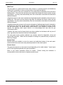
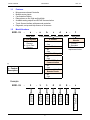
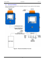
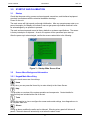
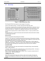
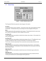
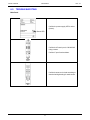
MODEL 4200-IG-2 (Up to 2 Sensors) MODEL 4200-IG-4 (Up to 4 Sensors) Industrial Grade Gas Monitor User Manual Technical Support Continental North America Toll Free 1-(800) 387-9487 Ph: +1 (905) 829-2418 Fx: +1 (905) 829-4701 A Product of Arjay Engineering Ltd. Oakville, Ontario, Canada www.ArjayEng.com MODEL: HARDWARE NO.: SOFTWARE NO.: SERIAL NO.: User Manual Model: 4200-IG Rev: 2.1 TABLE OF CONTENTS 1.0 2.0 3.0 4.0 5.0 6.0 7.0 INSTRUMENT OVERVIEW ............................................................................................3 1.1 Features .............................................................................................................5 1.2 Model Numbers ..................................................................................................5 1.3 Specifications .....................................................................................................6 INSTALLATION...............................................................................................................7 2.1 Main and Remote Panel Installation ..................................................................7 2.2 Sensor Installation..............................................................................................7 2.3 Electrical Installation ..........................................................................................8 2.4 Glossary of Symbols ..........................................................................................10 STARTUP AND CALIBRATION ......................................................................................11 3.1 Startup ................................................................................................................11 3.2 Screen Menu Background Information ..............................................................11 3.2.1 Keypad Main Menu Entry ....................................................................11 SYSTEM CONFIGURATION ..........................................................................................12 4.1 Diagnostic Information .......................................................................................12 4.2 Alarm Setup .......................................................................................................13 4.3 Sensor Setup .....................................................................................................14 4.4 Factory Setup .....................................................................................................15 4.5 Date and Time....................................................................................................15 4.6 System Test .......................................................................................................15 SENSOR CALIBRATION ................................................................................................16 TROUBLESHOOTING ....................................................................................................17 DETAILED ELECTRICAL AND DIMENSIONAL DRAWINGS .......................................18 TABLE OF FIGURES Figure 1 – System Overview ......................................................................................................................... 3 Figure 2 – Electrical Installation Overview .................................................................................................... 8 Figure 3 – Startup Main Screen View ......................................................................................................... 11 Figure 4 – System Configuration Main Screen View .................................................................................. 12 Figure 5 – Diagnostic Information Screen View .......................................................................................... 12 Figure 6 – Alarm Setup Screen View .......................................................................................................... 13 Figure 7 – Sensor Setup Screen View ........................................................................................................ 14 Figure 8 – Date & Time Screen View.......................................................................................................... 15 Figure 9 – System Test Screen View .......................................................................................................... 15 2 User Manual Model: 4200-IG 1.0 Rev: 2.1 INSTRUMENT OVERVIEW The Arjay Model 4200-IG monitors the inputs from various field sensors to provide a gas concentration display, alarms and interlocks. The monitoring system is comprised of one main control panel and a minimum of one remote alarm sensor transmitter. The panel can support multiple sensor inputs and signal types as per the part number ordered. Optional Remote alarm panels can also be added that will display and provide audio/visual alarms. Local or site specific regulations may apply to your application. Be aware and to comply with all applicable regulations for your installation. Figure 1 – System Overview 3 Model: 4200-IG User Manual Rev: 2.1 Main Panel The main panel is a wall mounted touch screen monitor in a general purpose (non-hazardous) location that is accessible for set-up and observation of the display and alarms. A low alarm relay for each zone is activated at a low setpoint and is indicated by the touch screen flashing yellow. The screen text also shows a low alarm and indicates the sensor number and gas concentration. The relay resets automatically when the concentration clears below the determined differential setpoint. A high alarm relay for each zone is activated at a high setpoint and is indicated by the touch screen flashing red. The screen text also shows a high alarm and indicates the sensor number and gas concentration. The relay resets automatically when the concentration clears below the determined differential setpoint. A high/high alarm relay common to all zones is activated at a high/high setpoint and is indicated by the screen text. The screen text also shows a high/high alarm and indicates the sensor number and gas concentration. An optional beacon and/or buzzer is also available to activate at this setpoint. The high/high alarm maybe latched to be acknowledged and reset after the gas concentration clears. If latched, the buzzer can be silenced during an alarm condition but the beacon will only turn off when a gas alarm has cleared and has been acknowledged. The main panel screen provides additional user interface menus for diagnostics, set-up and general help information. Menus can be accessed for viewing but a passcode entry is required to make any changes. Remote Panel Remote panels are available to mimic the screen and audio/visual alarms of the main panel. Access to the touch screen menus are password protected on the remote panels. Remote Sensor The panel will accept one or more sensor inputs depending on the model ordered. Typical inputs are 4-20 mA signals proportional to the gas concentration. Refer to your sensor transmitter manual for details. Routine testing and calibration is recommended to ensure the sensor is responsive and accurate. 4 User Manual Model: 4200-IG 1.1 Features 1.2 Rev: 2.1 Microprocessor based Controller Multiple sensor inputs Concentration Display Relay alarms on low, high and high/high Available analog outputs and RS-485 communication Touch Screen interface with passcode protection Diagnostic, set-up and Help menus on all screens Model Numbers 4200 ‐ IG ‐ x ‐ a x - # of Sensors 2 – Up to Two Sensors 4 – Up to Four Sensors b c d e ‐ f f – Custom vs. Standar x – Custom** z – Standard **Fill in the custom requirement below. a - Buzzer 0 – No 1 – Yes b - Strobe 0 – No 1 – Yes c – 4-20mA Output* 0 – No 1 – Yes d – RS-485 Modbus Communication 0 – No 1 – Yes e – Ethernet Hub For Remote Panels 0 – No 1 – Yes *Per Zone ** x – Custom Description 5 0 0 0 ‐ z Standard Configuration Selected 1 No Ethernet Hub Selected 1 No RS-485 Selected ‐ No 4-20mA Selected 2 Buzzer Selected ‐ 2 Sensors Selected 4200 ‐ IG Strobe Selected Example: User Manual Model: 4200-IG 1.3 Specifications Power Input: 100-240 vac, 50/60 Hz, 1.95A maximum User Interface: Touch Screen Full Colour 6 “ display on Main Panel Monochrome 4” on Remote Panel Outputs: Relay Output DPDT relay, 8 A @ 250 vac dry contacts Selectable failsafe or non-failsafe Programmable time delay: 0 – 1 hour; ON and/or OFF One relay each for: Low Setpoint per zone High Septoint per zone High/High common Sensor Accepts various sensor types Refer to your sensor manual for specifications Environmental: Ambient Temperature 0 to +55 °C Relative humidity 0 to 95% (non-condensing) Installation Category II Pollution Degree 2 Mechanical Specification: Refer to dimensional drawing 6 Rev: 2.1 Model: 4200-IG 2.0 User Manual Rev: 2.1 INSTALLATION NOTE: If any damage to the instrument is found, please notify an Arjay Engineering representative as soon as possible prior to installation. 2.1 Main and Remote Panel Installation Choose a mounting location in accordance with good instrument practice. Extremes of ambient temperature and vibration should be avoided (see specifications and installation drawing). Remote panels can be mounted up to 300 meters away from the main panel. Sensors can be mounted up to 1000 feets away from the main panel. Important Note: The controller is set in Failsafe mode (Factory Default). This means that the relays are in an energized state during normal operation. The N.O. relay contact will be held closed and the N.C. relay contact will be held open during a normal condition. This will allow the relay to return to it’s non-energized (shelf) state during an alarm, fault or power failure condition. Wire accordingly. 2.2 Sensor Installation Refer to sensor manual for more specification on location and wire type. The sensor is to be mounted near the targeted gas source and protected from extremes of temperature and damage. Keep the sensor accessible for routine calibration. Do not block with equipment or store materials or containers in front of the sensor. Gases may have densities greater than or less than air. Sensors should be mounted accordingly. Sensors targeting heavier than air gases should be mounted so the bottom of the sensor housing is approximately 250mm to 450mm (10” to18”) above floor grade to protect it from damage from cleaning equipment and minor washdown. The sensor should be mounted above any risk of flooding. Sensors targeting lighter than air gases should be mounted near the ceiling in a location that will be accessible for routine testing. Sensor location is application specific and may need to be in accordance with local regulations or engineered recommendations. 7 User Manual Model: 4200-IG 2.3 Rev: 2.1 Electrical Installation Refer to the drawings provided by the contractual engineer for your project and the drawings included with this manual. Figure 2 – Electrical Installation Overview 8 User Manual Model: 4200-IG Rev: 2.1 Wiring Chart (Depends on Sensor Selection) Two wire Loop Powered Transmitters (Sensor)* Transmitter Model Transmitter Wire Terminal + 24VDC Power Input HLM-2000-TX - Signal Output Panel Wire Terminal 24VDC Power Output Common (Not Used) + 4-20mA Input Three wire Loop Powered Transmitters (Sensor)* Transmitter Model HLM-2000-EX EC-Gold EC-Gold Dual IR-200 Transmitter Wire Terminal + 24VDC Power Input -Negative + 4-20mA Output Panel Wire Terminal + 24VDC Power Output Common + 4-20mA Input Four wire Loop Powered Transmitters (Sensor)* Transmitter Model IR-350 Transmitter Wire Terminal + 24VDC Power Input -Negative + 4-20mA Output -Negative *Shielded wire is recommended on all installation. Maximum wire length 1,000 feets @20 AWG. 9 Panel Wire Terminal + 24VDC Power Output Common + 4-20mA Input Model: 4200-IG 2.4 User Manual Rev: 2.1 Glossary of Symbols Attention, consult accompanying documents Attention, veuillez consulter les documents ci-joints. N Protective Earth Terre de protection Fuse Coupe-circuit; fusible Direct Current (DC) Courant continu Normally open relay contacts Contacts travail Normally closed relay contacts Contacts Repos Power off ArróÕ (mise hors tension) Power on Marche (mise sous tension) Live Sous tension L G Neutral Neutre 10 Ground Terre User Manual Model: 4200-IG 3.0 STARTUP AND CALIBRATION 3.1 Startup Rev: 2.1 Check that the power wiring, sensor and remote panel connections, and interfaced equipment are wired in accordance with the electrical installation drawings. Power On the unit. The main screen will light up and run through initialization. After any operator power start up or power interruption, the display will indicate it was non-gas power-up condition and that it must be acknowledged by an operator to proceed. The main and remote panels are set to factory defaults or customer specifications. The sensor is factory tested prior to shipment. As such, the system will be operational upon start-up. After the power-up is acknowledged, confirm the screen reads similar to the following. Figure 3 – Startup Main Screen View 3.2 Screen Menu Background Information 3.2.1 Keypad Main Menu Entry Below the touch screen are 4 touch keys. Home At any time, you can press the Home Key to return directly to the Home Screen Help This provides an overview of the system operation and components. Contact details for technical help are included at the end of the text. Tools Access this section to view or configure the screen and control settings, view diagnostics or to do a system alarm test. Silence During an alarm condition the audio can be silenced. Silencing at any panel will silence all panels. The audio alarm will automically re-set when the alarm clears. 11 User Manual Model: 4200-IG 4.0 Rev: 2.1 SYSTEM CONFIGURATION This section describes the screen, alarm and interface features accessed through the Tools on the Main Panel. Press “ “ Figure 4 – System Configuration Main Screen View 4.1 Diagnostic Information Figure 5 – Diagnostic Information Screen View This is a View Only screen. It provides the alarm and sensor setup details that have been entered for this unit. It also shows real time voltage and mA reading. Setup and sensor changes can be made through the passcode protected Alarm and Sensor Setup menu. 12 Model: 4200-IG 4.2 User Manual Rev: 2.1 Alarm Setup Figure 6 – Alarm Setup Screen View The Passcode 2000 will be required to make changes in this section. There are three alarm settings: Low alarm, High Alarm and High/High alarm The low alarm is typically used as a warning level that gas is present but at a safe level. It is not unusual to have trace levels of gas present during maintenance or process operations. A relay is provided for each zone. Determine your application requirement such as fan ventilation. The high alarm is typically used as an alarm condition for action. A relay is provided for each sensor. The high/high alarm is common to all sensors and will activate the buzzer and strobe if ordered. A common relay is provided. DELAY SETUP The low and high alarm delay settings are as follows: Delay ON. This is the time, in minutes and seconds, that the relays will delay before activating when the ppm setpoint has been reached. Delay ON is used to suppress a nuisance alarm that may be caused by a spurious or momentary alarm of gas. Delay OFF. The time, in minutes and seconds, that the relays will stay on after the ppm has dropped below the setpoint. Delay OFF is used to keep ventilation fans running after the sensor has cleared to assist ventilating any areas that may not be clear due to poor ventilation. FAILSAFE SETUP Failsafe will determine if the relays are energized or de-energized during a normal operating state (no alarm condition). If Failsafe is YES, the relay will be energized during a normal operating condition. An alarm or power failure will de-energize the relay to the alarm state. When in Failsafe mode and during a normal condition, the N.O. contact is closed and the N.C. contacts is open. WIRE ACCORDINGLY. COMMON Hi/Hi LATCH Select YES to latch the Hi/Hi relay when it alarms. In this mode, the alarm will need to be manually acknowledged by the Reset button on the Main screen after the gas condition has cleared. 13 Model: 4200-IG 4.3 User Manual Rev: 2.1 Sensor Setup Figure 7 – Sensor Setup Screen View The Passcode 2000 will be required to make changes in this section. Gas Name You can enter the gas name or identifier. This will show on the main screen adjacent to the gas concentration. This has been factory set according to the sensor shipped with this panel. Span This will determine the full concentration level of sensor. This is determined by the sensor type and is factory set according to the sensor shipped with this panel. Low Alarm ON This will determine the concentration at which the low alarm relay activates. At this setpoint, the screen will flash yellow. Low Alarm OFF This will determine the concentration at which the low alarm will turn off. This differential is used to suppress chattering of alarms if the gas concentration is hovering at the setpoint. The low alarm will clear automatically if the concentration levels drop below the alarm levels. High Alarm ON This will determine the concentration at which the high alarm relays activate. At this setpoint, the screen will flash red. The high alarm will clear automatically if the concentration levels drop below the alarm levels. High Alarm OFF This will determine the concentration at which the screen will indicate the gas condition has cleared. High/High Alarm This will determine the concentration at which the high/high alarm relay and alarms activate. This relay can be latched to be acknowledged after the gas clears. 14 Model: 4200-IG 4.4 User Manual Rev: 2.1 Factory Setup This screen is used to set the number of sensors inputs and enter the serial and firmware data. It is only accessible by a unique user name and passcode. This panel model can support up to four sensors. If a sensor is being added or removed from this panel, contact the factory with the serial number to update the factory database. The passcode can then be provided. 4.5 Date and Time The 4200-IG has a real time clock to remind users of impending calibration duties. The reminder frequency can be entered here. When a calibration is performed, Press the Record calibration icon to initiate reminder countdown timer. Figure 8 – Date & Time Screen View 4.6 System Test The Low, High and Common HI/HI relays can be tested for each zone by pressing appropriate Icon will turn green if selected. Push the appropriate alarm level for test. Figure 9 – System Test Screen View 15 Model: 4200-IG 5.0 User Manual Rev: 2.1 SENSOR CALIBRATION Refer to the specific sensor Instruction Manual attached to this manual for the sensor calibration details. The sensor is factory calibrated and will operate upon installation, however, the sensor response should be verified after installation with a calibration or test gas. Re-calibrate if necessary. Routine verification of the sensor response and confirmation of the panel alarms and interlocks is recommended. A minimum verification every 4 to 6 months is recommended. Re-calibrate as necessary. 16 Model: 4200-IG 6.0 User Manual Rev: 2.1 TROUBLESHOOTING Main Panel Confirm the power supply LED is active (Green). Confirm the Power Input is 100-240VAC using a meter. Confirm if input fuse has blown. Confirm that sensor is wired according to electrical wiring drawing for each sensor. Green LED 17 Model: 4200-IG 7.0 User Manual Rev: 2.1 DETAILED ELECTRICAL AND DIMENSIONAL DRAWINGS Drawings are included in this section that are specifc to your model ordered. If drawings are not included here, record the serial number on the left outside wall of the main panel and contact: ARJAY ENGINEERING TECHNICAL SUPPORT (800) 387-9487 +1 (905) 829-2418 www.arjayeng.com 18