1
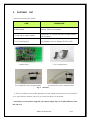
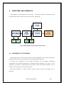
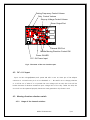
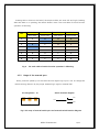
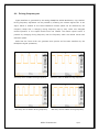
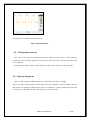
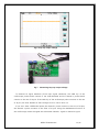
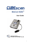
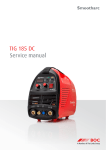
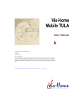
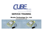
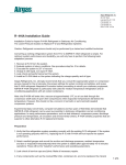
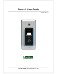
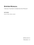
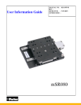
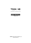
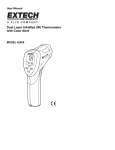
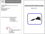
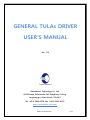
GENERAL TULAs DRIVER
USER’S MANUAL
Ver. 0.3
Piezoelectric Technology Co., Ltd.
#503 Sinnae Technotown, 485 Sangbong-1-dong,
Jungrang-gu, Seoul, Korea, 131-863
Tel. +82-2-3421-0370, Fax. +82-2-3421-0374
http://www.piezo-tech.com
PIEZO TECHNOLOGY
1/12
REVISON HISTORY
1. Ver. 0.1
2006/07/01
Made first edition.
2. Ver. 0.2
2006/08/19
Miner version up.
3. Ver. 0.3
2007/03/15
According to the hardware V2.1
This document contains information that is protected by copyright. No part of it may be
reproduced in any form without the permission from the copyright holders. This publication
is provided for informational purpose only. The manufacturer makes no represents or
warranties with respect to the contents or use of this manual and specifically disclaims any
express or implied warranties of merchantability or fitness for any particular purpose. The
user will assume the entire risk of the use or the results of the use of this document.
Further, the manufacturer reserves the right this publication and make changes to its
contents at any time without obligation to notify any person or entity of such revisions or
changes for technical improvement.
The information is subject to change without notice for technical improvement
Copyright all rights reserved by Piezoelectric Technology Co., Ltd
PIEZO TECHNOLOGY
2/12
CONTENTS
1.
INTRODUCTION ......................................................................................................................................... 4
2.
FUNCTION DESCRIPTION ...................................................................................................................... 4
3.
PACKING LIST ................................................................................................................................................ 5
4.
STRUCTURE AND INTERFACE .............................................................................................................. 6
4.1
MOVEMENT OF THE MOBILE .................................................................................................. 6
4.2
DC +9 V input ................................................................................................................................. 7
4.3
Moving direction selection switch ........................................................................................... 7
4.3.1
Usage of the internal switches ............................................................................................. 7
4.3.2
Usage of the external port .................................................................................................... 7
4.4
Driving frequency set ................................................................................................................... 9
4.5
Driving duty ratio set ................................................................................................................ 10
4.6
Step up voltage set .................................................................................................................... 10
PIEZO TECHNOLOGY
3/12
1.
INTRODUCTION
TULA (Tiny Ultrasonic Linear Actuator), as the subminiature motor using the piezoelectric
effect is developed for Zoom and AF(Auto Focus) of camera lens module, OIS(Optical Image
Stabilizer) and optical pick-up for the next generation optic storage devices such as HDDVD, BD(Blue ray disk).
The purpose of ‘General TULAs Driver’ is to move the simple mobile and to understand
basic principle movement. This kit would help you to understand the basic characteristics of
TULA, on changing duty ratio, voltage and frequency.
Single chip solution LT3572 on the hardware version v2.1. PCB is used. It’s integrated DC
step up part and H bridge part.
Refer that ‘TULA EV-KIT’ is more helpful instead of ‘General TULAs Driver’ to development
with TULA.
2.
FUNCTION
DESCRIPTION
The General TULAs Driver’s function is as follows.
1. Select moving directions
2. Variable driving frequency ( 10kHz ~ 100kHz )
3. Variable duty ratio
4. Variable driving voltage ( 12V~ 25V)
PIEZO TECHNOLOGY
4/12
3.
PACKING
LIST
Confirm the packing list, please.
ITEM
DESCRIPTION
1. Main Board
General TULAs Driver board
2. TULA with a simple mobile
TULA50-165 or TULA35-116 with a simple mobile
and a stander.
3. D.C. Power[option]
Free voltage input AC Adapter (DC 9V, 0.5A)
1. Main board
3. D.C. Power[option]
2.1 TULA50-165 with a simple mobile
2.2 TULA35-116 with a simple mobile.
Fig 1. Contents
A TULA is installed on the board generally and the simple mobile moves to left direction
or to right direction without any set if you press the switch on the board.
• According to the function upgrade, the above image may be a little different from
the real one.
PIEZO TECHNOLOGY
5/12
4.
STRUCTURE AND INTERFACE
The following is a block diagram of the system. The signal wave form is making to move
the mobile and Green blocks can be tune by user’s application.
Fig 2. Block diagram of the general TULAs driver
4.1 MOVEMENT OF THE MOBILE
The simple mobile can move left and right by pressing SWITCH on the board because the
general TULAs driver with the mobile has set properly before shipping.
To review the controllability of the mobile movement, you can measure mechanical
performance with external equipment by changing driving frequency, duty ratio or input
voltage to the ceramic. A simple mobile is just offer to check the simple movement. It is not
proper to test endurance or accurate operation.
The board dimension is 76mm x 43mm and the name of the user interface part is
following.
PIEZO TECHNOLOGY
6/12
Driving Frequency Control Volume
Duty Control Volume
Step-up Voltage Control Volume
Driver Output Port
External SW Port
Mobile Moving Direction Control SW
Power ON LED
D.C. 9V Power Input
Fig 3. The name of the user interface part
4.2 DC +9 V input
Input +9V DC voltage(500mA) and ‘power ON LED’ is turn on. Inner pin of the adapter
connector is +9V and outer pin is to be ‘GROUND’ or ‘-‘. Be careful not to change polarities
or it will be out of order. If it is inputted the over voltage such as 12V, the circuit will be
broken because of absolute maximum input voltage limit of the chip. Under the 8.5V, the
circuit will not be operated properly because a wave generation chip doesn’t work.
4.3 Moving direction selection switch
4.3.1 Usage of the internal switches
PIEZO TECHNOLOGY
7/12
Pressing SW1 or SW2 on the board, the simple mobile can move left and right. Pressing
SW1 and SW2 or no pressing, the mobile doesn’t move. The truth table of switch function
operation is following.
SW1
SW2
SIG X
SIG Y
Active LOW
Active LOW
Input Signal
Output Signal
1
1
0
0
0
2
1
0
1
1
3
0
1
0
1
4
0
1
1
0
5
0
0
0
0
6
0
0
1
0
7
1
1
0
0
8
1
1
1
0
No.
Fig 4.
The truth table of switch function operation is following.
4.3.2 Usage of the external port
Pin#1, pin#3 are pulled-up on the board and 5V digital logic input is set. So change the
mobile moving direction by the proper external logic signal or external SW.
Pin assignment J8
Switch function diagram
Pin #1
Pin #2
Pin #3
Fig 5. Pin map of external switch port and external switch function diagram
PIEZO TECHNOLOGY
8/12
4.4 Driving frequency set
Signal waveform is generated by the analog PWM(Pulse Width Modulation) chip, SG3525.
Driving frequency adjustment can be possible by trimming the volume register R11. It can
adjust 10kHz to 100KHz at this board. Maximum mobile speed can be detected by the
frequency sweep that is changing driving frequency step by step under user designed
mobile operation or the simple mobile which we offered. The mobile speed control is
possible by changing driving frequency near the frequency which the mobile moves with
maximum speed.
Refer that the TULA EV-kit can generate more precise and accurate waveform by the
DDS(Direct Digital synthesizer).
20% duty ratio at 38KHz driving frequency
20% duty ratio at 50KHz driving frequency
80% duty ratio at 38KHz driving frequency
80% duty ratio at 50KHz driving frequency
PIEZO TECHNOLOGY
9/12
50% duty ratio at 38KHz driving frequency
Fig 6. Driving waveform
4.5 Driving duty ratio set
Duty ratio of the period is adjusted the volume register R5 from 10% to 50%. Direction
switch can invert the input signal so the 10% duty ratio wave form coverts to the 90% duty
ratio waveform.
The maximum mobile speed can be detected at the 23% or 50% duty ratio generally.
4.6 Step up voltage set
Peak to peak voltage of PWM wave form is determined by step up voltage.
Step up voltage is adjusted the volume register R14. The maximum output voltage is 28V on
this board. The voltage is limited by the step up controller IC, LT3572, passive parts and PCB
routing. If it is operated over then 28V, step up IC can be broken.
PIEZO TECHNOLOGY
10/12
Fig 6. Step up output voltage
Fig 7.
Measuring Step up output voltage
To measure J4 signal waveform (TULA input signal waveform), the GND clip of the
oscilloscope probe should connect to the ‘PCB GROUND’ and the channel 1 probe should
connect to the one of J4 pins. If the GND clip of the oscilloscope probe connects to the one
of J4 pins, the inner element of the H bridge circuit IC can be burn out.
If you don’t have a differential probe, the channel 1 probe connects to the one of J4 pins,
the channel 2 probe connects to the other of J4 pins. Using the mathematical function of
the oscilloscope, review the signal that subtracted channel 1 signal to channel 2 signal.
PIEZO TECHNOLOGY
11/12
North American Distributor: Micro-Mechatronics, Inc.
www.mmech.com
Phone: 1-814-876-0894
email: [email protected]
Contact Piezoelectric Technology
Thanks for giving your interest to piezoelectric technology’s products. You should expect
the highest level of quality of our products. If you have any questions about principles of
USM(Ultra Sonic Motor) or need more information of products. Please, Contact us.
Home page
www.piezo-tech.com
Thanks for giving your interest to piezoelectric technology’s products. You should expect
the highest level E-mail
of quality [email protected]
our products. If you have any questions about principles of
+82-2-3421-0370
Telor need
USM(Ultra Sonic Motor)
more information of products, please contact us.
Fax
Address
+82-2-3421-0374
#503 Sinnae Technotown, 485 Sangbong1-dong,
Jungrang-gu, Seoul, Korea 131-863
PIEZO TECHNOLOGY
12/12