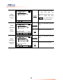
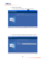
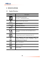
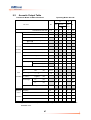
1
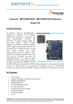
User Guide I II TM CUBESCAN BioCon-500 Bladder Volume Measurement System User Guide CAUTION: Federal Law restricts this device to sale by or on the order of a physician. • Information in this User Guide may change at any time without notice. Examples of ultrasound images in this User Guide are fictitious and do not in any way represent real patient data. For up-to-date user information, contact your local distributor or [email protected]. • Non-Mcube Technology product names may be trademarks or registered trademarks of their respective owners. Manufactured by Mcube Technology Co., Ltd. Room#803 Shinnae-Technotown, 485, Sangbong-Dong, Chungnang-Gu, Seoul, Korea 131-220 Tel: +82-2-3421-7780 Fax: +82-2-3421-7076 E-mail: [email protected] III IV Table of Contents 1 DEFINITIONS ............................................................................................. 1 2 GENERAL INFORMATION ......................................................................... 2 3 4 5 2.1 INDICATIONS FOR USE ..................................................................................................... 2 2.2 CONTRAINDICATIONS ....................................................................................................... 2 2.3 PRESCRIPTION STATEMENT ............................................................................................. 2 2.4 SAFETY .......................................................................................................................... 3 2.5 SAFE HANDLING PROCEDURES FOR TRANSPORTER ........................................................ 14 2.6 USER INTERFACE ICON DEFINITIONS .............................................................................. 14 INTRODUCTION ....................................................................................... 15 3.1 PRODUCT DESCRIPTION ................................................................................................ 15 3.2 SYSTEM COMPONENTS ................................................................................................. 17 3.3 FUNCTIONS OF EACH PART ............................................................................................ 18 SETUP ...................................................................................................... 22 4.1 INSTALLING OR REMOVING THE BATTERY ........................................................................ 22 4.2 CHANGING THE THERMAL PAPER ................................................................................... 23 4.3 CHARGING THE BATTERY MODULE OF THE BIOCON-500 4.4 CONNECTING THE PROBE TO THE SYSTEM ..................................................................... 26 4.5 ROLLING CART ASSEMBLY ............................................................................................. 27 TM .............................................. 24 HOW TO USE ........................................................................................... 38 5.1 QUICK GUIDE................................................................................................................ 38 5.2 DEVICE CONTROLS AND CONTEXTUAL MENUS ................................................................ 40 5.3 MEASURING URINE VOLUME .......................................................................................... 43 5.4 CHANGING THE PATIENT ID ............................................................................................ 49 5.5 LOADING THE SAVED DATA ............................................................................................ 50 5.6 SETTING THE CLINIC NAME ............................................................................................ 52 5.7 SETTING THE DATE & TIME ............................................................................................ 54 5.8 CUSTOMIZING OTHER SETUP OPTIONS .......................................................................... 55 5.9 CALIBRATING THE BIOCON-500 USING THE CALIBRATION KIT .......................................... 57 5.10 BUTTONS AND THEIR CONTEXTUAL MENU ABBREVIATIONS............................................... 60 V 6 7 5.11 SUMMARY OF EACH SCREEN AND ITS CONTEXT MENUS .................................................. 61 5.12 SUMMARY OF MENUS NOT SHOWN ON CONTEXT MENUS................................................. 65 THE OPTIONAL SOFTWARE(CUBESCANPC) ....................................... 66 6.1 GENERAL INFORMATION ................................................................................................ 66 6.2 INTENDED USE.............................................................................................................. 67 6.3 INSTALLING CUBESCANPC SOFTWARE .......................................................................... 67 6.4 UNINSTALLING SOFTWARE............................................................................................. 72 6.5 DEVICE DESCRIPTION.................................................................................................... 74 6.6 GETTING STARTED ........................................................................................................ 74 6.7 USE OF THE SOFTWARE ................................................................................................ 76 6.8 SETTING UP CUBESCANPC ........................................................................................... 81 TROUBLESHOOTING .............................................................................. 82 7.1 8 9 TROUBLESHOOTING ...................................................................................................... 82 MAINTENANCE ........................................................................................ 83 8.1 BATTERY CARE ............................................................................................................. 83 8.2 CHANGING THE BATTERY MODULES ............................................................................... 83 8.3 CHANGING THE THERMAL PAPER ................................................................................... 83 8.4 CLEANING & DISINFECTION............................................................................................ 83 8.5 W EEKLY INSPECTION ..................................................................................................... 84 8.6 DEVICE REPAIR ............................................................................................................. 85 8.7 DISPOSAL ..................................................................................................................... 85 SPECIFICATIONS .................................................................................... 86 9.1 SYMBOL DIRECTORY ..................................................................................................... 86 9.2 ACOUSTIC OUTPUT TABLE ............................................................................................. 87 9.3 DEFINITIONS AND SYMBOLS ........................................................................................... 89 9.4 SPECIFICATION OF COMPONENTS................................................................................... 94 10 ENVIRONMENTAL CONDITIONS ............................................................ 96 TM 10.1 BIOCON-500 ............................................................................................................. 96 10.2 BATTERY MODULE ........................................................................................................ 97 11 GLOSSARY .............................................................................................. 98 12 REFERENCES .......................................................................................... 99 VI 1 DEFINITIONS These definitions are used in this user guide. WARNING: Describes precautions necessary to prevent injury or loss of life. CAUTION: Describes precautions necessary to protect the products. IMPORTANT: Describes information that a user should know for safe and effective use of this system. SCAN : Tactile switch SCAN : Context menu based on system state (Screen) 1 2 GENERAL INFORMATION 2.1 Indications for Use The BioCon-500TM is a B-mode pulsed-echo ultrasound device. The BioCon500TM is intended as a portable battery-operated device. The BioCon-500TM projects ultrasonic energy through the abdomen of the patient obtaining images of the bladder in order to calculate the urine volume non-invasively. The BioCon-500TM is intended to be used only by qualified medical professionals. Contraindications for the BioCon-500TM are fetal use and use on pregnant patients. 2.2 Contraindications Do not use the BioCon-500TM on following cases: a) Fetal use or pregnant patients. b) Patients with ascites. c) Patients with open or damaged skin. d) Wounds in the suprapubic region. 2.3 Prescription Statement Caution: Federal Law restricts this device to sale by or on the order of a physician. 2 2.4 Safety This guide covers components, function, maintenance, storage, and precautions needed to use this system. All users must read and thoroughly understand this entire guide prior to using the BioCon-500TM. This section has information on safe use of the BioCon-500TM (Electrical Safety, Battery Safety, EMC (Electromagnetic Compatibility), Equipment Safety). WARNING: Risk of explosion: To avoid the risk of injury, do not operate the device in the presence of flammable gasses or anesthetics. The hazard of potential explosion exists. 2.4.1 Electrical Safety This device meets IEC 60601-1, ClassⅠ, Type BF isolated patient-applied parts safety requirements. This device complies with the applicable medical equipment requirements published in the Canadian Standards Association (CSA), European Harmonized Standards, and Underwriters Laboratories(UL) safety standards. Please review and follow the following safety warnings. WARNING: The power supply should be properly grounded. The power supply must be connected to an AC socket that is medical grade or equivalent. The grounding pin must not be removed or tampered with. Do not use the device if the power cord is damaged. Do not open the device’s enclosures. All servicing, except battery and printer paper replacement, must be made by a qualified technician. Inspect the transducer and cable prior to using the device. Do not use if the transducer or cable is damaged. Use the device within operating conditions specified in chapter 10 “Environmental conditions.” Do not use the device with any defibrillator at the same time. Use accessories only recommended by Mcube Technology. Do not use if the transducer that has been immersed beyond the specified cleaning or disinfection level. 3 WARNING: The device should be used with ultrasonic gel either applied on the probe or patient’s abdomen. Thus, users should avoid using this device on patients with skin disease or injury. Power Cord: Make sure the power cord is the correct type for your area. The equipment has a universal power adapter that allows operation at either 100-120V AC or at 200-240V AC without the need for user adjustment. Always use a hospital grade power cord with the correct plug type. The cord must be rated for 125VAC at 15A, and be of type SJT or better. Adapter: The device complies to the above standards only when used with the power cord included.. Only use adapters supplied by Mcube Technology. (see chapter 9.4 Specification of adapter ). Computer connection: When connecting the BioCon-500TM to a computer, the computer must be certified to EN/IEC/CSA/UL 60950 or 60101-1 standard to maintain the device’s compliance to EN/IEC/CSA/UL 60601-1-1 standard. Transmission of data: When transmitting data to or from a computer, make sure that the BioCon-500TM, any accessories, and the computer are at least 2 meters or 6.5 feet away from the patient. 4 2.4.2 Battery Safety BioCon-500TM uses a Lithium-ion battery pack. To ensure safe use of the battery, observe the following warnings and cautions. If there are any problems with the battery module, immediately discontinue use of the battery and contact Mcube Technology or your local distributor. WARNING: The battery module has built in safety mechanisms. Do not disassemble or tamper with the battery pack. Only use the charger that is supplied with the Unit. Contact Mcube Technology or your local distributor for replacements. Do not charge the battery outside of the recommended conditions, as it may damage the battery resulting in possible leakage of the electrolyte or explosion (see chapter 9.4 Specification of adapter ). Charge the batteries only when the ambient temperature is between +10℃ and +40℃ (+50 - +104℉)(in door use). Do not short-circuit the battery. Short circuiting the battery may cause rapid heating resulting is possible explosion. To avoid short-circuiting, do not let the battery come in contact with metal objects at any time, especially when transporting. Only use the manufacturer’s recommended battery. Do not connect the battery in reverse polarity. Do not charge the battery in reverse polarity as it may cause the battery to rapidly heat, swell or even explode. Do not use a battery pack when something appears abnormal. Such as unusual smell, deformation, discoloration, etc. If electrolyte leakage occurs, do not touch the liquid. If it should come into contact with the skin or eyes, immediately seek help from a doctor. If the battery does vent, avoid any contact with the smoke. Do not expose the battery to water, moisture, or any type of liquid. Do not use or store the battery in temperatures above 60℃ 5 or next to any heat source. Doing so can cause the battery pack to swell, and explode. WARNING: Do not abuse the battery pack. Doing so can cause damage to the battery resulting in a potentially unsafe situation. CAUTION: When connecting the battery module to a console, be careful about polarity. Be sure to securely fasten the battery cover. Long term storage: If the system is not likely to be used for more than a week, remove the battery module from the device and store it according to the recommended storage conditions. (See chapter 10 “Environmental conditions”) IMPORTANT: To lengthen lifetime of the battery module, it is recommended to charge up to 75% and to discharge to 20%. If the battery pack lasts less than 5 minutes after a full charging, replace the battery with a new one. 6 2.4.3 Electromagnetic compatibility The BioCon-500TM has been tested and found to comply with the electromagnetic compatibility (EMC) limits for medical devices as set forth in IEC 60601-1-2:2001. These limits are designed to provide reasonable protection against harmful interference in a typical medical installation. CAUTION: To reduce the performance degradation of this device, use medical devices that comply with IEC 60601-1-2 EMC Standards in the vicinity. Do not use this device simultaneously with devices having high EMI levels. Electrostatic discharge (ESD) is a commonly occurring phenomenon Electrostatic especially discharge when can the humidity is low. cause damage to the transducer or the system. The following procedures can be useful in reducing the likelihood of ESD: anti-static spray on carpets, anti-static spray on linoleum, and anti-static mats. 2.4.3.1 Manufacturer’s declaration - electromagnetic emissions The BioCon-500 is intended for use in the electromagnetic environment specified below. The customer or the user of the BioCon-500 should assure that it is used in such an environment. Immunity test RF Emissions Compliance Electromagnetic environment -guidance Group 1 The BioCon-500 uses RF energy only for its CISPR 11 internal function. Therefore, its RF emissions are very low and are not likely to cause any interference in nearby electronic equipment RF Emissions Class A CISPR 11 The BioCon-500 is suitable for use in all establishments, other than domestic and those directly connected to the public low-voltage power supply network that supplies buildings used for domestic purposes Harmonic emissions Class A 7 IEC 61000-3-2 Voltage fluctuations/ Complies Flicker emissions IEC 61000-3-3 2.4.3.2 Manufacturer’s declaration - electromagnetic immunity The BioCon-500 is intended for use in the electromagnetic environment specified below. The customer or the user of the BioCon-500 should assure that it is used in such an environment. Immunity test IEC 60601 Compliance level Electromagnetic environment Test level Electrostatic ±6kV Contact ±6kV Contact Floors should be wood, discharge (ESD) ±8kV air ±8kV air concrete or ceramic tile. If IEC 61000-4-2 floors are covered with synthetic material, the relative humidity should be at least 30%. Electrical fast ±2kV for power ±2kV for power Mains power quality should transient/burst supply lines supply lines be that of a typical IEC 61000-4-4 ± 1kV for ± 1kV for commercial or hospital input/output lines input/output lines environment. Surge ±1kV differential ±1kV differential Mains power quality should IEC 61000-4-5 mode mode be that of a typical ±2kV common ±2kV common commercial or hospital mode mode environment. 8 Voltage dips, <5% Uт <5% Uт Mains power quality should short (>95% dip in Uт) (>95% dip in Uт) be that of a typical interruptions and for 0.5cycle for 0.5cycle commercial or hospital voltage 40% Uт 40% Uт environment. If the user of variations (60% dip in Uт ) (60% dip in Uт ) the BioCon-500 requires on power supply for 5 cycle for 5 cycle continued operation during input lines 70% Uт 70% Uт power mains interruptions, IEC 61000-4-11 (30% dip in Uт) (30% dip in Uт) it is recommended that the for 25 cycle for 25 cycle BioCon-500 ultrasound <5% Uт <5% Uт system be powered from an (<95% dip in Uт ) (<95% dip in Uт ) uninterruptible power supply for 5 s for 5 s or a battery. 3 A/m 3 A/m Power frequency magnetic Power frequency (50/60Hz) fields should be at levels magnetic field characteristic of a typical IEC 61000-4-8 location in a typical commercial or hospital environment. NOTE Uт is the a.c. mains voltage prior to application of the test level. 2.4.3.3 Manufacturer’s declaration - electromagnetic immunity The BioCon-500 is intended for use in the electromagnetic environment specified below. Users of the BioCon-500 should ensure that use occurs in such an environment Immunity test IEC 60601 Compliance test level level Electromagnetic environment Conducted 3 Vrms 3 Vrms Portable and mobile RF communications RF 150 kHz to 150 kHz to equipment should be used no closer to any IEC 61000-4- 80MHz 80MHz part of the BioCon-500, including cables, 6 than the recommended separation distance calculated from the equation applicable to the frequency of the transmitter. 9 Radiated RF 3 V/m IEC 61000-4- 80 MHz to 3 2.5GHz 3 V/m Recommended separation distance 80MHz to 2.5GHz where P is the maximum output power rating of the transmitter in watts (W) according to the transmitter manufacturer and d is the recommended separation distance in meters (m). Field strengths from fixed RF transmitters, as determined by an electromagnetic site survey, a should be less than the compliance level in each frequency range. b Interference may occur in the vicinity of equipment marked with the following symbol : NOTE 1) At 80MHz and 800MHz, the higher frequency range applies. NOTE 2) These guidelines may not apply in all situations. Electromagnetic propagation is affected by absorption and reflection from structures, objects and people. a Field strengths from fixed transmitters, such as base stations for radio (cellular/cordless) telephones and land mobile radios, amateur radio, AM and FM radio broadcast and TV broadcast cannot be predicted theoretically with accuracy. To assess the electromagnetic environment due to fixed RF transmitters, an electromagnetic site survey should be 10 considered. If the measured field strength in the location in which the BioCon-500 is used exceeds the applicable RF compliance level above, the BioCon-500should be observed to verify normal operation. If abnormal performance is observed, additional measures may be necessary, such as re-orienting or relocating the BioCon-500. b Over the frequency range 150kHz to 80MHz, field strengths should be less than [V1] V/m. 11 2.4.4 Equipment Safety To prevent damage to the system and/or accessories, observe the following cautions. CAUTION: A dirty transducer can degrade the accuracy of the system. Clean the transducer with a soft cloth dampened in a mild soap or detergent. Dropping a transducer or impact on a transducer can cause the system to malfunction or be inaccurate. Do not drop or shock the transducer. To avoid damaging the cable or transducer connector, handle them with care. Do not immerse the system or the transducer beyond the level in specified in 8.4 “Cleaning & Disinfection” If the system is not likely to be used for more than a week, charge the battery up to about a 75% charge level, remove the battery module from the device and store it according to storage conditions of the battery. This step will help maximize the lifetime of the battery. (See chapter 10 “Environmental conditions”) The device has a setting to power down automatically if not used during a specified time period. This setting may be adjusted by selecting the ‘Auto Power’ option in ‘Setup Menu’. The device will not power on without a battery installed. When measuring the urine volume of a patient, ensure that the probe’s SCAN button is on the right side of the patient. When using the system on a medical cart, ensure that the cart is placed on a flat and level surface. The safe level of immersion for the probe is marked by the border between the cap of the probe and the body of the probe. Do not immerse beyond the ‘B’ portion of the probe illustrated in the figure to the left. Only use the transducer which shipped with your unit The transducers are not interchangeable between units, They are calibrated to a specific machine. If changing the 12 probe associated with a machine, it is necessary to calibrate the two prior to deployment 13 2.5 Safe Handling Procedures for Transporter Quarantine: Packages that are crushed, punctured or torn open to reveal contents should not be placed into deployment. Such packages should be isolated until the shipper has been contacted, provides disposition instructions and, if appropriate, arranges to have the product inspected and repacked. Spoiled Product: In the event that damage to packaging results in damage to the battery causing released electrolyte, the spill should be contained and the shipper should be contacted for instructions. 2.6 User Interface Icon Definitions Symbol Meaning Indicates a male patient Indicates a female patient Indicates a battery more than 75% charged Indicates a battery 50~75% charged Indicates a battery 25~50% charged Indicates a battery 5~25% charged Indicates the battery is near depletion or depleted 14 3 INTRODUCTION 3.1 Product Description BioCon-500TM is a portable ultrasound system intended to measure the volume of urine in a patient’s bladder. BioCon-500TM transmits ultrasound signals into the abdomen of a patient and receives the echoed signals. Using the echoed signals, the system determines the bladder’s outline and calculates the volume of the bladder based on the outline. BioCon-500TM has a Pre-Scan function, which shows a live ultrasound image of a horizontal planar cross-section of the bladder found by using the echoed signals. The Pre-Scan function helps in locating the bladder and improving accuracy. A user can print the results using a built-in thermal printer immediately after measurements are taken. Also using the optional CubeScanPC software, one can upload saved data in a device’s flash ROM to a computer for later review of the images. Fig 1 BioCon-500 TM System Front View 15 16 3.2 System Components 3.2.1 Packaging list Part number Parts Description 3110100041 Console 3110100037 Ultrasound probe 2.8MHz 4110100719 AC cord Hospital grade NEMA 5-15 4110100069 4110100744 Adapter(Power Supply) Model: MW160KA1641F52 Or Model: GTM21097-5012 4110100718 Thermal paper Built in(57mm width) – 2 rolls 4110100714 Gel Ultrasound transmission gel 5110100009 User guide User guide 3.2.2 Optional components Part number Parts Description 3110100032 Medical cart Optional 5110100028 PC upload software CD 4110100018 Battery Pack Module Li18S 4110100070 USB cable USB A-B cable(1.8M (Optional)) 17 CubeScanPC setup CD (Optional) 3.3 Functions of Each Part * Ref: This connection is used with optional CubeScanPC software. Fig 2 System Diagram (excluding power supply) 18 3.3.1 Console Fig 3 Front of the console No. Item 1 LCD 2 Thermal printer Function Remark Displays menus and information. Prints out the measured data. Green lamp(left) : Adapter connection status On: Adapter connected. 3 Indication lamp Off: Adapter disconnected* Yellow lamp(right) : Charging status On: Charging 4 ENTER & arrow buttons Depends on the system state. 5 POWER button Turns the system on / off 6 PRINT button Depends on the system state. 7 SCAN button Depends on the system state. * During pre-scan and/or scan operation, the yellow lamp will turn off regardless of the charging state. 19 Fig 4 Right-side view of the console No. Item 1 USB terminal 2 Probe terminal Function Remark Terminal for USB connection with a computer. Connects a probe to a console. Fig 5 Left-side view of the console No. Item 1 Adapter terminal Function Remark Terminal for adapter connection to a console. Fig 6 Rear view of the console No. Item 1 Handle 2 Battery cover Function Can be used to facilitate carrying Cover for the battery compartment 20 Remark 3.3.2 Ultrasonic Probe Fig 7 Ultrasonic probe and cable No. Item 1 Probe cap 2 Cable 3 Connector 4 SCAN button Function Transmits and receives Remark ultrasound signals Connects the probe to console. Connects the ultrasonic cable to the console The same function as a SCAN button on the console. 21 4 SETUP 4.1 Installing or Removing the Battery The battery is installed in a bay in the BioCon-500TM. When changing the battery or removing the battery for storage, follow these instructions. 1) Turn the system off. Power off Disconnect accessories 2) Disconnect all connections from the console. 3) Loosen the two screws using a screwdriver. 4) Remove the battery cover. IMPORTANT: When removing the battery cover, be careful to not bend the cover. 5) Pull out the battery using the strap on the battery. 6) Insert the new battery. When inserting, the top side of the battery (the side having LED) should be down (facing the bottom of the unit) and the strap on the battery should be be facing outwards. The battery cannot be properly installed if the orientation is incorrect. WARNING: To avoid the risk of explosion, only use batteries 22 recommended by Mcube Technology. CAUTION: 4.2 Never use excessive force to install the battery. Changing the Thermal Paper 1) Open the printer cover as shown to the left. 2) Pull out the empty bobbin. 3) With the printer paper in one hand, unroll a small length of the paper and insert into the unit as shown. 4) Close the printer cover after inserting the paper. CAUTION: Be sure to insert the paper in the correct orientation. To avoid damaging the system: - Only use thermal paper recommended by Mcube Technology. - Only print when the thermal paper is correctly loaded. 23 4.3 Charging the Battery Module of the BioCon-500TM 1) Connect an AC cord to a DC adapter. 2) The picture shows an adapter with the AC cord properly connected. 3) Connect the DC jack to the adapter terminal of the console. 4) The pricture shows a console with the proper connection to the DC jack. 5) Connect the AC plug to a grounded socket. 24 6) Check the color indicator on the console. *Green indicator: Tells that the adapter connected and AC power is present. The system is ready to charge and be operated. *Yellow indicator: Denotes that the system is charging. When the battery is fully charged, the yellow indicator goes off. *Fully charging the battery may take up to 10 hours.. WARNING: Only use AC Adapters recommended by Mcube Technology. To avoid electric shock, only use sockets with a ground pin. 25 4.4 Connecting the Probe to the System 1. Find the white mark on the connector of the probe. 2. Align the probe cable to the probe terminal with the white mark (①) on the probe connector up. After aligning, push the probe cable straight in until there is a click sound. * To disconnect the probe from the console, grasp the black plastic ring (2) on the probe connector and pull out. 3. Check to make sure the connection is secure. 26 4.5 Rolling Cart Assembly 27 28 29 30 31 32 33 34 35 36 37 5 HOW TO USE 5.1 Quick Guide 38 39 5.2 Device Controls and Contextual Menus BioCon-500TM has 8 buttons on the main console. Only one of the buttons ( POWER ) has fixed functionality. It is used for turning the system on or off. The other 7 buttons navigate the contextual menus and have varying function. Contextual Menus in the bottom part of the display consist of an option and a corresponding button. For example, “SCAN-S,” means that the option is SCAN, and a tactile switch is SCAN . Table below explains the context menus and system state. Switch SCAN PRINT LEFT RIGHT UP DOWN ENTER SCAN - SEX LOAD SETUP P_ID - - EXIT - - MUP MDOWN SELCT SCAN PRINT* RESET SAVE SETUP PLANE - SCAN - - - - STOP - - PRINT ERASE TOP NEXT PLANE - - CFIRM CANCEL - - - - RCURS EXIT MLEFT* MRIT* MUP* MDOWN* INPUT - EXIT LCURS RCURS NUP NDOWN - - - LCURS RCURS NUP NDOWN ENTER - - OUP ODOWN - - ENTER State Top Screen PSCAN Setup Screen Scan Results PSCAN Screen Pre-Scan Screen Load Screen Erase Confirm Screen Clinic Name Input Screen Patient ID Input Screen Setup Data/Time Setup Other Option 40 Screen Upload - - - - - - - Screen - Context menus marked * are not displayed in bottom of the display. 5.2.1 Number Functions in each context menu Context Function Menu 1 SCAN Initiate a bladder volume scan. 2 PSCAN 3 SEX 4 LOAD 5 SETUP 6 P_ID Go to patient ID input screen. 7 EXIT Go to previous system state. 8 MUP Move the position cursor upward (circular). 9 MDOWN 10 SELCT Select the item selected by position cursor. 11 PRINT Print scan results or loaded data according to system state. 12 RESET Clear the data in a current session and go to Top Screen. 13 SAVE 14 PLANE Show next two planes images and related numeric data. 15 STOP Stop pre-scanning and go to previous system state. 16 ERASE Pre-Scan for positioning the bladder. Toggle between male and female. Load the saved data. Go to setup menu. Move the position cursor downward (circular). Save the data of current session to flash ROM. Go to Erase Confirm Screen for erasing current loaded data. 17 CFIRM Erase current loaded data from flash ROM. 18 CANCEL Go to Load Screen without erasing current loaded data. 19 MLEFT Move the position cursor in Screen Keyboard to the left. 20 MRIT Move the position cursor in Screen Keyboard to the right 21 MUP Move the position cursor in Screen Keyboard to upwards 22 MDOWN 23 LCURS Move the position cursor in Screen Keyboard to downwards Move the cursor to left. 41 24 RCURS Move the cursor to right. 25 NUP Increase the value in current cursor (curcular). 26 NDOWN Decrease the value in current cursor (curcular). 27 INPUT Input the current character of the Screen Keyboard under the position cursor except in case of bottom line of the Screen Keyboard. 28 ENTER Change the selected Setup Item option to the option on the display and save the Setup Item option to the flash ROM. And go to Setup Menu. 29 OUP 30 ODOWN 5.2.2 Number Show the next option upward for the current Setup Item. Show the next option downward for the current Setup Item. Combined Switches Combined Function Active states Switches 1 ENTER + UP Brightness Up Top Screen Scan Results Screen 2 ENTER + DOWN Brightness Down 3 ENTER + LEFT Change Image Contrast 42 Load Screen Scan Results Screen Load Screen 5.3 Measuring Urine Volume 1) Charge Battery. Charge the battery by connecting the AC Adapter to the AC main and to the console. 2) Turn on the system Turn the system on by pressing and holding POWER switch for more than 1 second. Then you can see the Top Screen as follows. Fig 8 Top Screen 3) Select patient type. Select patient type by pressing LEFT switch (SEX option) on Top Screen. Each time a user presses the LEFT switch, the patient type mark will be changed. : A male patient : A female patient 4) Apply the ultrasound gel Apply the ultrasound gel on the patient’s abdomen, above about 3~4cm above pubic symphysis. 5) Aim toward bladder Put the ultrasound probe on gel applied to the patient’s abdomen and aim at the location the bladder is expected to be in. 43 IMPORTANT: When you put the probe on the patient’s abdomen, be sure that the SCAN switch of the probe places on the right side of the patient. IMPORTANT: Conditions to degrade the accuracy of the measurement: - When a patient has had supra-pubic or pelvic surgery - A patient with catheter in his or her bladder - A patient with scar, sutures, staples or incisions in his or her abdomen - Air-gap between probe head and the skin of the patient - Use of the probe with unclean probe head 6) Use care when scanning in above conditions. Locate the bladder with the Pre-Scanning function. Press SCAN switch to start Pre-Scanning and start displaying the prescan image on the main display. The position where the bladder image is largest and most centered is the optimal place to start the scan process. 44 Fig 9 Pre-Scan Screen IMPORTANT: The Pre-Scan is executed only when ‘Prescan Enable’ in setup menu is ‘ON’. When ‘Prescan Enable’ is off, a normal scan will be executed the SCAN button is pressed on Top Screen. 7) After locating the optimal scanning location, press the SCAN button to start the bladder scan. The screen during normal bladder scanning is as follows. 45 Fig 10 During-Scan Screen 8) Verify the scan results and rescan if needed. After a normal scan, results will be displayed on the main display as follows. Fig 11 Scan Results Screen In the aiming information in the Scan Results Screen, if the crossing of the aiming lines is not well centered on the bladder contour, you must re-aim and scan again. Also verify the bladder image and the detected bladder contour are in line with each other. If needed, re-aim and scan again. 46 How to re-aim Fig 12 Diagram for re-aiming 47 9) Review, save and print scan results To review other planes press DOWN (PLANE option) on the Scan Results Screen. To save the scan results press RIGHT (SAVE option) on the Scan Results Screen. To print the scan results press PRINT on the Scan Results Screen. PLANE option is not displayed on the context menus in bottom part of LCD. IMPORTANT: During one session a user may scan more than 1 time. In this case the scan results with the largest urine volume will be saved and printed. In case there are multiple scans with the same urine volume, the most recent will be saved and printed. If a user saves twice in same session, the data that was previously saved will be overwritten. Only one data set will be saved per each session. BioCon-500TM can save up to 5 scans. If a user saves more than 5 scans, the oldest scan will be overwritten with the newest scan data.. 10) Finish scan. After finishing the scan, wipe the ultrasound gel off the patient and the probe. 48 5.4 Changing the Patient ID 1) Press DOWN (P_ID menu) on the Top Screen. Then a user can see the Patient ID Input Screen as follows. Patient ID Cursor 0 1 2 3 4 5 `6 7 8 9 Context Menus LCURS-← NUP-↑ NDOWN-↓ RCURS-→ EXIT-P Fig 13 Patient ID Input Screen 2) Change the Patient ID. To move the cursor, press LEFT (LCURS option) or RIGHT (RCURS option). To change the value at the selection point, press UP (NUP option) or DOWN (NDOWN option) IMPORTANT: The patient ID consists of 10 digits. The patient ID is not saved in flash ROM, so after restarting the system the patient ID will be reset to ‘0000000000’. 3) Go to Top screen by pressing PRINT (EXIT option) after editing the patient ID. 49 5.5 Loading the Saved Data Press RIGHT (P_ID menu) on the Top Screen. The Load Screen will be as follows. Fig 14 Load Screen The following information will be displayed on the Load Screen a) Two plane images b) Areas for two planes images c) Plane number d) Measurement date & time e) Patient ID f) Urine Volume g) Aiming information *To review next saved data, press UP (NEXT option). * To browse other planes press DOWN (PLANE option). * To print current loaded data, press PRINT (PRINT option). * To return to Top Screen, press RIGHT (TOP option). * To erase current loaded data, press LEFT (ERASE option). 50 The following is an Erase Confirm Screen. In this screen to cancel, press LEFT (CANCEL option). To confirm the deletion of the current ,data, press PRINT (CFIRM option). Fig 15 Erase Confirm Screen 51 5.6 Setting the Clinic Name 1) Press UP (SETUP option) on the Top Screen. The Setup Screen will display as follows. Fig 16 Setup Screen 2) With the selection cusor to the left of ‘Clinic Name’, press ENTER (SELCT option). The Clinic Name Input Screen will be displayed as follows. Clinic Name Input Window Title << Input Clinic Name >> Cursor Position Cursor In Screen Keyboard MC Screen Keyboard A B C D E F G H I J K L M N O P Q R S T` U V W X Y Z 0 1 2 3 4 5 6 7 8 9 _ - # Backspace Space DONE Clear Context Menus RCURS-↓ INPUT-E Fig 17 Clinic Name Input Screen 52 EXIT-P These items are displayed in the Clinic Name Input Screen, a) Title ‘<<Input Clinic Name>>’ b) A Clinic Name Input Window c) A Software Keyboard d) And Contextual Menu Options Within the software keyboard, the bottom ‘keys’ have special function. Number Screen Keyboard Function 1 Backspace Delete one character. Same function as backspace key on a computer’s keyboard. 2 Space Blank character. 3 DONE Save the current clinic name shown in Clinic Name Input Window and return to Setup Screen. 4 Clear Delete all characters in Clinic Name Input Window 3) Edit the clinic name by using the displayed keyboard.. To move around the keyboard use LEFT , UP , DOWN , RIGHT . These switches are not specified in Contextual Menu Options. IMPORTANT: Pressing PRINT (EXIT option), will cause the system to return to the Setup Screen without saving the name. 4) After editing the clinic name, press ENTER with selection cursor under the DONE option on the keyboard. 53 5.7 Setting the Date & Time 1) Press UP (SETUP option) on the Top Screen. 2) With the selection cursor to the left of ‘Set Data/Time’, press ENTER (SELCT option). The selection cursor in the Setup Screen will be moved to the right as shown below. Position Cursor In Setup Screen Clinic Name Set Date/Time Print Option Flash Store Setup Print Scan Result Auto Power Calibration Prescan Enable Exit MCUBETECH 2007/10/10 15:00 Raw Image On Cursor B-Mode 7 minutes Return On Context Menus LCURS-← NUP-↑ Fig 18 NDOWN-↓ RCURS-→ ENTER-E Setup Date/Time Screen 3) Changing the date and time is done through using the contextual options. To move the cursor, use LEFT (LCURS option) or RIGHT (RCURS option). To change the numeric data above the cursor use UP (NUP option), and DOWN (NDOWN option). 4) When done editing the date and time, save the changes using ENTER (ENTER option). The position curser will return to the left of the screen. 54 5.8 Customizing Other Setup Options 1) Press UP (SETUP option) on the Top Screen. 2) Move the position cursor using UP (MUP option) or DOWN (MDOWN option) to select the desired option. 3) Press ENTER (SELCT option). The position cursor will move to the right of the selected item. 4) Browse the options by using LEFT (OUP option) or RIGHT (ODOWN option) Position Cursor In Setup Screen MCUBETECH 2007/10/10 15:00 Raw Image On Clinic Name Set Date/Time Print Option Flash Store Setup Print Scan Result Auto Power Calibration Prescan Enable Exit Setup Item Opion B-Mode 7 minutes Return On Context Menus OUP-← ODOWN-→ ENTER-E Fig 19 Setup Item Option Screen 5) Select setup item option ENTER (ENTER option). Then the selection cursor moves to the left hand side of the Setup screen 55 The following table lists the customizable setup options Setup Item Option Meaning Value Only Print only the Urine volume Raw Image Print the Urine volume, and all 12 planar images and bladder contour Print Option Walls Print the Urine volume, and the contours of the 12 planes All Planes Print the Urine volume and the images and bladder contours of all 12 planes Flash Store ON To turn on the flash store function OFF To turn off the flash store function Contour Scan Result Show bladder outlines without images in the Scan Results Screen B-Mode Show bladder outlines with images in the Scan Results Screen Off Auto Power Prescan Enable To turn off “auto power off” 3 minutes Turn the system off if there is no input for 3 minutes 5 minutes Turn the system off if there is no input for 5 minutes 7 minutes Turn the system off if there is no input for 7 minutes 10 minutes Turn the system off if there is no input for 10 minutes ON Turns on Pre-Scan functionality OFF Turns off Pre-Scan functionality 56 5.9 Calibrating the BioCon-500 Using the Calibration Kit 5.9.1 Preparing the calibration kit 1) Open the cap of the calibration kit and pour 0.9 % saline solution up to the fill-mark of the calibration kit. 2) Close the cap. 3) Align the probe scan button with the arrow mark on the calibration kit, then insert the probe into the holder ensuring it is secure. IMPORTANT: Purge all air bubbles form the system. You can also use distilled or DI water instead of the saline. Purge the system of air bubbles in this case as well. 5.9.2 Calibrating the BioCon-500 with the calibration kit 1) Connect the probe which is positioned into the probe holder of the calibration kit to the console 2) Turn on the console Screen Display in the BioCon-500 Description The Top Screen. Press UP to go to setup menu. Setup Menu Go to “Calibration” setup using UP or DOWN. 57 Press ENTER key. Select the “Start” setup value using LEFT or RIGHT. Calibration top screen To start calibration, press ENTER. Screen during calibration. To stop the calibration process, press DOWN in the first path or second path. In the third path and fourth path, a user cannot interrupt the calibration. 58 If there are any errors during calibration, the main display will show the message “Calibration has failed!!!” “ERROR: First Path, Not Enough Water(EC1)”. In the error message, “First Path” means the calibration steps when the system detected any error during calibration. “Not Enough Water” means additive information about the error state. This additive information is displayed for only EC1 error. “EC1” means the error code during calibration. The screen when the calibration is done successfully. The date and time when the successfully calibration is displayed is done in the bottom part of the LCD screen. IMPORTANT: The BioCon-500 returns to the top screen when the calibration process is terminated or stopped. To leave the calibration screen, press the down key (only effective in the first and second path of the calibration process) for more than 5 seconds or turn off the system by pressing the power key. 59 5.10 Buttons and their Contextual Menu Abbreviations The context menus in bottom line of the display is shown like this – ENTER-E ENTER is a context menu and E is the abbreviation for the button to press to activate the ENTER option. Tactile switch Abbreviation in context menu SCAN S PRINT P LEFT ← UP ↑ DOWN ↓ RIGHT → ENTER E * The membrane button on the probe has the same function as the SCAN button. 60 5.11 Summary of Each Screen and its Context Menus Following table summarizes each screen‘s contextual menus in the system. Name Screen Menu SCAN SEX Function Start Pre-Scan or normal scan in a new session. Change the patient type. To change the patient ID, Top P_ID Screen goes to the Patient ID Input Screen. LOAD SETUP - To review saved data, goes to the Load Screen. To setup system options, goes to the Setup Screen. - During Scanning SCAN Activate the normal scan. Pre-Scan Screen STOP SCAN RESET Scan Results PLANE Screen SETUP SAVE 61 Stop the Pre-Scan and return to the Top Screen. Start Pre-Scan or normal scan in the current session. Exit the current session and return to the Top Screen Displays the next two plane images. Goes to the Setup Screen. Saves the results current session. of the ERASE PLANE Load Screen NEXT TOP PRINT Goes to the Erase Confirm Screen. Displays the next two plane images. Display next saved session.. Return to the Top Screen. Print the current data. Cancel the erasure. CANCEL Erase Confirm Erase current saved session Screen ERASE LCURS NUP Patient ID NDOWN Input Screen RCURS EXIT MDOWN MUP Setup Screen SELCT EXIT 62 data. Move the selection cursor to the left. Increase the value above the cursor. Decrease over the value above the cursor. Move the selectrion cursor to the right. Return to the Top Screen. Move the selection cursor downward. Move the selection cursor upward. Select the current option for customization. Return to the Top Screen. Move the selection cursor to RCURS Clinic the right. Select the letter above the Name INPUT Input Screen selection cursor. Return to the Setup Screen. EXIT LCURS NUP Setup Date/Time NDOWN Move the selection cursor to the left. Increase the value above the cursor. Decrease over the value above the cursor. RCURS Move the cursor to the right. ENTER Save the date and time. Browse to the next option OUP Other upward. Browse to the next option Options’ ODOWN downward. Setup Set the option to currently ENTER displayed value. IMPORTANT: “Upload Screen” will be shown during upload Upload the data to the computer. There is no active Screen menu in Upload Screen. Start calibration. CSTART Setup Calibration Top Return to the Top Screen. Screen EXIT 63 Stop the calibration process. A Setup user can stop the calibration during step 1 and Calibrating STOP Screen step 2. DOWN Press and hold for more than 5 seconds to stop calibration. Retry the calibration process CSTART Setup over. Calibration Error Return to the Top Screen. Screen EXIT Retry the calibration process CSTART Setup over. Calibration Completion Return to the Top Screen. Screen EXIT 64 5.12 Summary of Menus not Shown on Context Menus There are menus which were not shown on context menus but have its function in that screen. Following table summarizes those menus and their functions in each screen. Screen Option Button Scan Results Screen PRINT PRINT MLEFT LEFT MRIT RIGHT MUP UP MDOWN DOWN Clinic Name Input Screen 65 Function Print the results of the current session. Move the selection cursor to the left. Move the selection cursor to the right Move the selection cursor up Move down the selection cursor 6 THE OPTIONAL SOFTWARE(CubeScanPC) Skip this part if you do not have or use the optional CubeScanPC software. 6.1 General Information Copyright ⓒ 2007 Mcube Technology Co., Ltd. All rights reserved. The contents of this manual are the property of Mcube Technology Co., Ltd. Any reproduction in whole or in part is strictly prohibited. This manual correctly describes the software and its functions at the time of publishing of the CD-ROM. However, as modifications may have been carried out since the production of this manual, the device package may contain one or more addenda to the manual. This manual including any such addenda must be read, before using the software. The following situations void any guarantee(s) and obligations of Mcube Technology: - The software is not used according to the enclosed manuals and other accompanying documentation. - The software is installed or modified by persons other than Mcube Technology certified service technicians ** “SETTING UP The BioCon-500TM” function is only available to service engineers and technicians. This User Guide covers the basics of installing CubeScanPC software and using the upload function between the BioCon-500TM and a PC. The following information is covered in this manual. • Warning statements. • Intended use. • PC requirements. • Installation • Operation • Technical data 66 6.2 Intended Use This CubeScanPC software is intended to allow scan image data to be uploaded to a PC from the BioCon 500.. The uploaded scan data may be reviewed, maintained, and filed on a PC. Additionally it may be printed from a PC. BioCon-500TM The BioCon-500TM is a B-mode ultrasonic device that is intended for the measurement of residual urine volume. The device automatically calculates the volume using ultrasound images from a three-dimensional sector probe. The BioCon-500TM saves scan image data for up to 5 sessions. 6.3 Installing CubeScanPC Software 6.3.1 PC Requirements Recommended PC requirements are as follows. • Operating system: Windows XP • Processor: Pentium III, 500MHz (minimum). • Main memory: 256MB (minimum). • Hard disk: minimum 100MB free space. • CD-ROM: minimum 10x. • Monitor Resolution: minimum 1024*768. • Keyboard and Mouse • USB port: USB1.1 or USB 2.0 IMPORTANT: There is an additional need of about 282KB of storage space for each session’s scan data. 67 6.3.2 Installing Software 1) Insert the software CD into the CD-ROM drive. 2) Double click CubeScanPC_Setup.exe file in the root folder of the CD. a) Preparing setup dialog will be displayed as follows. b) Choose setup language and click Next. 68 c) Initial screen for installation - Click Next. d) Customer Information Dialog - Please enter your name and company name. - Then click Next. 69 e) Ready to start Installation. - You are ready to start installation. Click Install to continue. f) Setup status dialog will be displayed during installation as follows. 70 g) Finish dialog. - Setup is successfully completed. Click Finish. 71 6.4 Uninstalling Software 1) Click on start in Windows. 2) Click control panel. 3) Click Add or Remove Programs in control panel. 4) Click Remove for remove of CubeScanPC program. 72 5) To confirm, click Yes. 6) Status dialog will be displayed as follows. 7) To finish, click Finish. 73 6.5 Device Description 6.5.1 Parts Lists Parts list included along with this software is as below: • This User Guide • 1 CD with CubeScanPC Software • 1 USB cable 6.5.2 System Schematics Fig 20 System Schematics 6.6 Getting Started Connecting to the BioCon-500TM. 1) Connect the BioCon-500TM with a USB cable to a PC while the BioCon500TM is powered-off. 2) Click START button of Windows. 3) Click ALL PROGRAM 4) Click Mcube Technology 5) Click CubeScanPC The initial screen is shown below: 74 6) Turn the BioCon-500TM on. After powering-on, the program’s title bar should be changed into as below (USB:Connected): WARNING: If there is no sign of connection after the BioCon-500TM has been powered on for more 1 minute, make sure that the connections are correct and secure and retry. If there is still no message of connection, the device may need servicing.. 7) The connection is established when the USB state is ‘Connected’. 75 6.7 Use of the Software 6.7.1 Upload the Scan Data This function is used to transfer session scan data from the BioCon-500TM. 1) Check the connection status between PC and the BioCon-500TM in title bar. It should read “USB : Connected” 2) Click File in a menu bar. 3) Click Upload. 4) During upload, a status dialog will display the progress of the upload. 5) When completed, the data will be displayed on the PC as follows. 76 6) Enter the patient information and save the contents using Save button. 7) Refer to Printing the Scan Data for printing. IMPORTANT: If the BioCon-500TM is powered off without saving the scan data into the flash rom, it will not be saved and will be lost Be sure to save the data that is intended to be uploaded to a PC. 77 6.7.2 Upload All Saved Scan Data This function is used to upload all the stored data in flash memory. 1) Check the connection status between PC and the BioCon-500TM in title bar. 2) Click File in a menu bar. 3) Click Upload All Saved Images. 4) During upload a status dialog will display the progress of the upload 5) When completed, the data will be displayed on the PC as shown in the single upload case. In the multiple upload case, each session will have a dedicated window. 6) Enter the patient information and save the contents using Save button for each window open The BioCon-500TM can store up to 5 scanning sessions 7) Refer to Printing the Scan Data for printing. 78 6.7.3 Deleting All Saved Scan Data This function is used to delete all saved data in the BioCon-500TM. 1) Check the connection status between PC and the BioCon-500TM in title bar. 2) Click File in menu bar. 3) Click Delete All Saved Images. 4) Dialog box for confirmation is presented. When you press Yes, all stored data will be deleted. IMPORTANT: Functionality that deletes individual stored datum is not yet implemented. 6.7.4 Contrast/Brightness Control Modifies the contrast and brightness of the image. 1) Click on Tools in the menu bar. 2) Select Brightness/Contrast 3) A dialog box will display allowing for the adjustment of the brightness and contrast. Use the slider bars to adjust the brightness and contrast using either a mouse or the keyboard’s arrow keys. 79 IMPORTANT: Tools menu is only available if a data file is open 6.7.5 Changing Image Size This function is used to modify the size of displayed image. Available sizes are 50%, 75%, 100% and 200% 1) Click on Tools in the menu bar. 2) Select Image Size. 3) Click on the desired size IMPORTANT: Images will always print at 100%. This will not impact the print size 6.7.6 Printing the Scan Data This function is used to print scan data from a PC to a printer. 1) Click on File in the menu bar. 2) Select the desired printer 3) Click Print. IMPORTANT: You can preview the layout through the Print Preview in the menu bar 80 6.8 Setting up CubeScanPC This is used to change the CubeScanPC’s software settings. The only available function is to input the Facility Name. 6.8.1 Facility Name 1) Click Setup in the menu bar. 2) Select CubeScanPC Setup. 3) CubeScanPC Setup Dialog is displayed. Enter the desired facility name. 4) Click OK. * “Handshake Mode” does not have any effect on the operation of the CubeScanPC Software currently. IMPORTANT: Facility name used here is independent of the one in Device Configuration menu and is only used for printing purposes. Facility name in Device Configuration is saved in the BioCon-500TM and not impacted by this option. 81 7 TROUBLESHOOTING 7.1 Troubleshooting Error message Description Actions Use again after charging the battery. BATTERY LOW!!! Battery low IMPORTANT: To lengthen the lifetime of the battery, charge the battery when it is around 20% charged. 1. Ensure the printer cover is closed. If the cover is open, close the cover and try printing again. 2. Check if the thermal paper is empty. If NO PAPER! Printer Error there is no paper, insert a new roll of paper and try printing again. 3. If the above steps do not successfully solve the problem, contact an authorized servicer. Check if the connection between the probe NO SCANHEAD Connection and the console is secure. If the above Error does not successfully solve the problem, contact an authorized servicer. ERROR IN CABLE CONNECTION! Transducer Contact an authorized servicer.. circuit open 82 8 MAINTENANCE 8.1 Battery Care Do not overcharge the battery and avoid deep discharges. To lengthen the battery’s lifetime, use the system while the battery is between 25%~75%. The BioCon-500TM does draw power from the battery even while powered off. To avoid deep discharge, disconnect the battery from the system if it will not be used for more than a week. When storing the battery, pre-charging to about 75% is recommended. 8.2 Changing the Battery Modules See 4.1 “Installing or removing battery” 8.3 Changing the Thermal Paper See 4.2 “Changing the thermal paper” 8.4 Cleaning & Disinfection 8.4.1 Cleaning 1) Cleaning outer case (housing) of the system a) Wipe the main body using soft cloth dampened with isopropyl alcohol or any other appropriate hospital cleaning solution.. Do not allow liquids to leak into the device while cleaning.. b) Thoroughly dry the device with a clean, soft cloth before re-deployment. 2) Cleaning the probe Cleaning the surface of the Probe; a) Disconnect the Probe from the system. b) Wipe the probe cap using a soft cloth dampened with isopropyl alcohol or an appropriate hospital cleaning agent. c) Then wipe with water-dampened cloth. d) Dry with a soft, clean cloth. WARNING: To avoid electric shock disconnect the system from the AC mains and the battery. 83 CAUTION: Do not immerse the console or the probe. Do not use harsh, corrosive chemicals (e.g. hydrochloric acid, bleach). 8.4.2 Disinfection 1) Disinfection of the Probe a) Clean the Probe prior to disinfection. b) Dampen a soft cloth with disinfected solution listed in the table below. c) Wipe the probe with a dampened cloth. d) Air dry or towel dry with a soft, clean cloth. e) Inspect the Probe and the cable for any damage such as cracks. WARNING: To avoid electric shock disconnect the system from the AC mains and the battery CAUTION: Do not immerse the console or the probe. Disinfectants Lists for the Probe disinfection Use any glutaraldehyde based disinfectant to disinfect the Probe. Following table lists compatible disinfectants. Disinfection Solutions Type Country of Origin Manufacturer Cidex Liquid USA Johnson & Johnson Cidex 7 Liquid USA Johnson & Johnson Metricide 14 Liquid USA Metrex Research Inc. Metricide 28 Liquid USA Metrex Research Inc. CAUTION: Do not use Cidex Plus or Metricide Plus 30 to disinfect the device. Cidex Plus or Metricide Plus 30 will attack and damage the plastic enclosure. This will be considered as abuse and will void the warranty. 8.5 Weekly Inspection a) Try to scan with the probe disconnected, check if the “NO SCANHEAD” message is displayed on the main display. b) Thoroughly inspect the probe for cracks or leakage. 84 c) Inspect the probe cable for any damage. d) When scanning, check for any abnormal noise emanating from the probe head. 8.6 Device Repair Faults not described in section “7. Troubleshooting” are intended to be serviced by a certified technician. In the event a situation outside of those described in the section occurs, contact an authorized servicer or Mcube Technology for servicing. 8.7 Disposal The device and accessories may contain environmentally hazardous materials (mineral oil, lead, battery pack, etc). When they have reached the end of its useful service life, return them to the Mcube Technology, or follow your local regulations for hazardous waste disposal. 85 9 SPECIFICATIONS 9.1 Symbol Directory Symbol Description Type BF patient applied part (B= body, F= floating applied part) Attention, see the User manual. Direct current(DC) Alternating current(AC) IPX1 Degrees of protection against the ingress of water. CE marked in accordance with the Medical Device Directive UL classification mark for Canada and the U.S. Collect separately from other household waste (see European Commission Directive 93/86/EEC). Refer to local regulations for disposal. Date of manufacture Reference number Serial number 86 9.2 Acoustic Output Table Transducer Model: 2.8MHz Transducer Operating Mode: B-mode TIS Index Label MI scan TIB non-scan non- Aaprt≤1 Aaprt>1 Global Maximum Index Value: 0.307 0.002 X 0.13 X FDA Units pra pr.3 (MPa) P Wo (mW) min of [Pα(zs),Ita,α(zs)] [W.3(z1),ITA.3(z1)] zs z1 (cm) X Associated zbp zbp (cm) X Acoustic zb zsp (cm) z at max. Ipi, α zsp (cm) deq(zb) deq(zsp) (cm) fawf fc (MHz) Dim of Aaprt X Parameter scan X IEC TIC X 0.002 X 0.13 0.50 X X 4.70 X 2.63 X X X 2.63 (cm) 1.40 X X X 1.40 Y (cm) 1.40 X X X 1.40 td PD (µsec) prr PRF (Hz) Other pr at max. Ipi pr@PIImax (MPa) Information deq at max. Ipi deq@PIImax (cm) Focal Length FLX (cm) 7.60 X X 7.60 FLY (cm) 7.60 X X 7.60 IPA.3@MImax (W/cm ) Ipa, α# at max. MI Operating 2.63 0.77 400.00 0.49 X 2 3.73 2.80 Frequency 2.80 X X X 2.80 Control Conditions … Notes: (a) This index is not required for this operating mode; see section 4.1.3.1 of NEMA Standard UD-3. 87 (b) This probe is not intended for transcranial or neonatal cephalic uses. (c) This formulation for TIS is less than that for an alternate formulation in this mode. # No data are reported for this operating condition since the global maximum index value is not reported for the reason listed. Acoustic Measurement Precision and Uncertainty All entries in the below table have been obtained at the same operating conditions that produce the maximum index value. The measurement precision and uncertainty values are determined by repeated measurements. Precision Uncertainty (% of standard deviation) (95%) pr.3 5.4% ±21% Wo 6.2% ±28% fc 4.8% ±14% Parameter 88 9.3 Definitions and symbols MI the Mechanical Index TISscan the Soft Tissue Thermal Index in an auto-scanning mode TISnon-scan the Soft Tissue Thermal Index in a non-auto-scanning mode. TIB the Bone Thermal Index. TIC the Cranial Thermal Index. Aaprt the area of the active aperture (square centimeters). pr.3 the derated peak rarefractional pressure associated with the transmit pattern giving rise to the value reported under MI (megapascals) Wo For TIB and TIC: time average acoustic power at the source, in milliwatts. (Also see the definitions for W 01 and W01x1 that follow.) For TIS scan, W o = W o1 + Wo1x1 For TIS non–scan, W o = Wo1x1 Wo1: For scanning modes and/or scanning components of combinational modes: time average acoustic power at the source, per cm, in milliwatts. This is the acoustic power emitted from the central 1–cm length, in the scan direction, of the aperture corresponding to the scanned pulses. Wo1x1: For non–scanning modes and/or non–scanning components of combinational modes: time average acoustic power at the source, per cm2, in milliwatts. This is the acoustic power emitted from the central 1 cm2 of the active non–scanned aperture through which the highest acoustic power is being transmitted. W.3(z1) the derated ultrasonic power at axial distance z1 (milliwatts). ITA.3(z1) the derated spatial-peak, temporal-average intensity at axial distance z1 (milliwatts per square centimeter). z1 the axial distance corresponding to the location of max[min(W .3(z), zbp ITA.3(z) x 1 cm2)], where z = zbp (centimeters). (centimeters). 1.69 Aaprt zsp For MI, the axial distance at which pr.3 is measured for TIB, the axial distance at which TIB is a maximum (i.e., zsp = zB.3) (centimeters). deq(z) the equivalent beam diameter as a function of axial distance z, and is equal to [(4/)(W o/ITA(z))]0.5 where ITA(z) is the temporal-average intensity as a function of z (centimeters). 89 fc is the center frequency (MHz). For MI, fc is the center frequency associated with the transmit pattern giving rise to the maximum reported value of MI. For TI, for combined modes involving transmit patterns of unequal center frequency, fc is defined as the overall range of center frequencies of the respective transmit patterns. Dim. of Aaprt the active aperture dimensions for the azimuthal and elevational planes (centimeters). PD the pulse duration (microseconds) associated with the transmit pattern giving rise to the reported value of MI. PRF the pulse repetition frequency associated with the transmit pattern giving rise to the reported value of MI (Hz). pr@PIImax the peak rarefactional pressure at the point where the free field, spatial-peak pulse intensity integral is a maximum (megapascals). See Section 6.2.4.1 of the Output Display Standard, entitled "Measurement Methodology for Mechanical and Thermal Indices". deq@PIImax the equivalent beam diameter at the point where the free field, spatial-peak pulse intensity integral is a maximum (centimeters). See Section 6.2.5.1 of the Output Display Standard, entitled "Measurement Methodology for Mechanical and Thermal Indices". FL the focal length, or azimuthal and elevational lengths, if different (centimeters). IPA.3@MImax the derated pulse average intensity at the point of maximum reported MI (Watts per square centimeter). p_ MPa The Peak Rarefactional Acoustic Pressure is the maximum of the modulus of the negative instantaneous acoustic pressure expressed as a positive number. 2 mW/cm ISPTA The maximum value of the temporal average derived intensity in an acoustic field. For systems in combined operating mode, the time interval over which the temporal average is taken is sufficient to include any period during which scanning may not be taking place. System settings a User selectable system settings which may include Application, SV and Focal Length. 90 Ip mm This is the distance from the transducer output face to the point of maximum pulse-pressure-squared integral (or max mean square acoustic pressure for continuous pressure for CW) wpb6 (||) mm This is the -6dB pulse beam width in the beam axis (X) at the point of max pulse-pressure-squared integral (or max mean square acoustic pressure for continuous pressure for CW). If the beam widths in X and Y differ than less than 10%, there is no need to specify both. For scanning modes, the beam-widths shall correspond to the central scan line only. wpb6 (_|_) mm This is the -6dB pulse beam width in the elevational axis (Y) at the point of max pulse-pressure-squared integral (or max mean square acoustic pressure for continuous pressure for CW). If the beam widths in X and Y differ than less than 10%, there is no need to specify both. For scanning modes, the beam-widths shall correspond to the central scan line only. Prr kHz Pulse Repetition Rate is the rate of successive pulses or tone bursts and applies to single element non-scanning systems and automatic scanning systems. Srr Hz Scan Repetition Rate is the rate of the same identical point of successive frames, sectors, or scans and applies to automatic scanning systems (modes) only. Output dimensions beam mm b Output beam dimensions are the dimensions of the ultrasound beam (-6dB pulse beam width) in a specified direction normal to the beam alignment axis and at the transducer output face. In scanning modes, these shall refer to the center scan line only. Fawf MHz The Arithmetic-mean Acoustic Working Frequency is the arithmetic mean of the frequencies f1 and f2 at which the amplitude of the spectrum of the acoustic signal first becomes 3dB lower than the peak amplitude. 91 APF c % Acoustic Power-up Fraction is the ratio of the peak rarefactional acoustic pressure when the system is in Power-up mode to the maximum value of the peak rarefactional acoustic pressure for any system settings of a specified mode of operation. This ratio is determined from measurements made at the position which yields the maximum pulse-pressure-squared integral (or maximum mean square acoustic pressure for CW) AIF d % Acoustic Power-up Fraction is the ratio of the peak rarefactional acoustic pressure when the system is in Initialization mode to the maximum value of the peak rarefactional acoustic pressure for any system settings of a specified mode of operation. This ratio is determined from measurements made at the position which yields the maximum pulse-pressure-squared integral (or maximum mean square acoustic pressure for CW) e Maximum power mW This is the Maximum Temporal Average power output. For scanning modes, this shall be the total power output of all the acoustic pulses. 2 mW/cm Iob Output Beam Intensity is the temporal-average power output divided by the output beam area With the probe connected cycle power on the system. Power-up mode Write down the mode to which the system powers up. Initialization mode Usually, it is “B” mode. Write down “N/Af “ where it denotes “system settings do not change on new patient entry” Acoustic Write down “YES “ if the system is supplied with an output output freeze facility. freeze Itt mm Transducer to Transducer output face distance is the distance along the beam alignment axis between the surface containing the active face of the transducer or elements and the transducer output face (usually the lens thickness) 92 Its mm Transducer Standoff distance is the shortest distance between the transducer output face and the patient entry plane. The term “contact” is used to connate direct contact between the transducer output face and the patient. Inclusive modes Make a note of the Inclusive Modes for this particular declaration which are not being declared separately. 93 9.4 Specification of Components Item Power Features - AC 100-240V, 50/60Hz - Model: Adapter MW160 KA1641F52 (16V DC, 2.8A) (or GTM21097-5012 (12V DC, 4.17A) - Comply with UL 60601-1. - Battery Pack: Li18S Battery cell: Li-ion rechargeable (2P-2S) Battery - Scan: 4 hours – 1 scan in every 15sec** - Standby: 6 hours** - Charging time: Fully charging a completely discharged battery may take up to 10 hours. - sector scan - 2.8MHz ultrasound frequency Ultrasound Probe - B-mode scan image - scan angle : 120° - water resistance: rated at IPX1(only probe) - Diameter: 14mm Transducer - Resonant frequency:2.8MHz - Bandwidth: minimum 40% at 6dB - Penetration depth(normal patient): 18cm Thermal printer - Built in(57mm width) - 5.6〃 STN LCD Display - 320×240 pixels - 16 gray levels Range External Interface - Bladder volume range: 0 - 999ml - Accuracy*: ±15%,±15ml (0 - 999ml) - USB 2.0 basic 94 Classification of protection against electric shock Water resistance Mode of operation - ClassⅠ equipment - Type BF equipment - Main body: Ordinary equipment - Probe: rated at IPX1 - Continuous operation. Dimension - 375(L)×240(W)×116(H) mm Language - English * Accuracy: According to the scanning instruction, and scanning on a Mcube Technology tissue-equivalent bladder phantom. ** Battery operation time: - For a new battery module fully charged - Tested on Mcube Technology’s test conditions 95 10 ENVIRONMENTAL CONDITIONS 10.1 BioCon-500TM 1) Operating conditions Condition Description Ambient temperature range +10 – +40℃ (+50 - +104℉) Relative humidity +30% – +75% non-condensing Atmospheric pressure range +700hPa – +1060hPa 2) Storage conditions Condition Description Ambient temperature range -10 – +60℃ (+14 - +140℉) Relative humidity +20% – +80% non-condensing Atmospheric pressure range +600hPa – +1060hPa CAUTION: If you are not using this device more than a week, please disconnect battery from the device. Store the battery in accordance with the recommended conditions. 96 10.2 Battery Module 1) Battery Storage Conditions Condition Description -10 – +30℃ (+50 - +86℉) ≤ 1 Year Ambient temperature range -10 – +45℃ (+50 - +113℉) ≤ 3 Month -10 – +60℃ (+50 - +140℉) ≤ 1 Month Relative humidity +20% – +80% non-condensing Atmospheric pressure range +600hPa – +1060hPa CAUTION: Prior to storing the battery, charge it to about 75%. 97 11 GLOSSARY B-Mode A kind of ultrasound imaging mode. Displays the brightness information corresponding to the amplitude of the signal. Console The main device with the LCD display. Contextual The menu displayed in the bottom of LCD based on the system menu state. Session The time a user starts to scan on Top Screen, to right before returning to the Top Screen again. Transducer Device that transforms one form of energy into another form of energy. Ultrasound transducer transforms electric energy into acoustic energy and vice versa. Transducer in this guide means ultrasound transducer. 98 12 References AIUM: Medical Ultrasound Safety, American Institute of Ultrasound in Medicine, Laurel, MD, 1994. AIUM: Acoustic Output Labeling Standard for Diagnostic Ultrasound Equipment: A Standard for How Manufactures Should Specify Acoustic Output Data, Revision 1, American Institute of Ultrasound in Medicine, Laurel, MD, 2008. AIUM/NEMA: Standard For Real-Time Display of Thermal and Mechanical Acoustic Output Indices On Diagnostic Ultrasound Equipment, Revision 2. NEMA Standards Publication UD 3-2004; American Institute of Ultrasound in Medicine, Laurel, MD; National Electrical Association, Rosslyn, VA; 2004a. AIUM/NEMA: Acoustic Output Measurement Standard for Diagnostic Ultrasound Equipment, Revision 3. NEMA Standards Publication UD 2-2004; American Institute of Ultrasound in Medicine, Laurel, MD; National Electrical Association, Rosslyn, VA; 2004b. Health Canada: “Guidelines for the safe use of diagnostic ultrasound,” Cat. H46-2/01255E, Ministry of Public Works and Government Services Canada, 2001. IEC: IEC 60601-1, Medical Electrical Equipment – Part 1: General Requirements for Safety, International Electrotechnical Commission, 2004. UL 60601-1, Medical Electrical Equipment – Part 1: General Requirements for Safety, Underwriter Laboratories Inc, 2003. CSA C22.2 No. 601.1B-90, Medical Electrical Equipment – Part 1: General Requirements for Safety, Canadian Standards Association, 2006. IEC: IEC 60601-2-37, Medical electrical equipment – Part 2-37: Particular requirements for the safety of ultrasonic medical diagnostic and monitoring equipment, International Electrotechnical Commission, 2007. ISO: ISO-10993-1, Biological Evaluation of Medical Devices Part 1: Evaluation and 99 Testing, 2003. FDA Guidance: Information for Manufacturers Seeking Marketing Clearance of Diagnostic Ultrasound Systems and Transducers, 2008 FDA Guidance: General Principles of Software Validation; Final Guidance for Industry and FDA Staff, 2002. IEC: IEC 61157, Standard means for the reporting of the acoustic output of medical diagnostic ultrasonic equipment, International Electrotechnical Commission, 2007. MDD 93/42/EEC, Medical Device, Office for the Official Publications of the European Communities, 2003. Woo Sung Hong, Sun Young Ham, Tong-Wook Kim, Jeong-Seok Seo, Sang-Kuk Yang. Usefulness of a Sonographic Bladder Scan for Uroflowmetry and the Evaluation of the Anxiety Level Associated with Uroflowmetry. The Korean Journal of Urology 2007:48(06):633-637 Chung B, Lee T, Yang J H. The Diagnostic Value of Portable Bladder Volume Measurement (BVMS) with Real Bladder Image in the Measurement of Bladder Volume According to the Different Angling of Transducer. The Korean Journal of Urology 2006:47(06):1320-1326 Bodker B, Lose G. Postoperative urinary retention in gynecologic patients. Int Urogenecol J Pelvic Floor Dsyfunct 2003;14:94-97 McNaughton-Collins M, Barry MJ. Managing patients with lower urinary tract symptoms suggestive of benign prostatic hyperplasia. Am J Med 2005;118:1331-9 100 Mcube Technology, Co., Ltd. Room #803 Shinnae-technotown, 485, Sangbong-Dong, Chungnang-Gu, Seoul, 131-220, Korea Tel. Fax. E-mail Web site : +82-2-3421-7780 : +82-2-3421-7076 : [email protected] : www.mcubetech.co.kr MUM-BioCon 500(Rev. 5.1)